WO2022097613A1 - 撮像システム、3dモデル生成システム、コントローラ、方法及びプログラム - Google Patents
撮像システム、3dモデル生成システム、コントローラ、方法及びプログラム Download PDFInfo
- Publication number
- WO2022097613A1 WO2022097613A1 PCT/JP2021/040319 JP2021040319W WO2022097613A1 WO 2022097613 A1 WO2022097613 A1 WO 2022097613A1 JP 2021040319 W JP2021040319 W JP 2021040319W WO 2022097613 A1 WO2022097613 A1 WO 2022097613A1
- Authority
- WO
- WIPO (PCT)
- Prior art keywords
- image pickup
- pickup devices
- unit
- controller
- imaging
- Prior art date
- Legal status (The legal status is an assumption and is not a legal conclusion. Google has not performed a legal analysis and makes no representation as to the accuracy of the status listed.)
- Ceased
Links
Images


Classifications
-
- H—ELECTRICITY
- H04—ELECTRIC COMMUNICATION TECHNIQUE
- H04N—PICTORIAL COMMUNICATION, e.g. TELEVISION
- H04N23/00—Cameras or camera modules comprising electronic image sensors; Control thereof
- H04N23/45—Cameras or camera modules comprising electronic image sensors; Control thereof for generating image signals from two or more image sensors being of different type or operating in different modes, e.g. with a CMOS sensor for moving images in combination with a charge-coupled device [CCD] for still images
-
- G—PHYSICS
- G03—PHOTOGRAPHY; CINEMATOGRAPHY; ANALOGOUS TECHNIQUES USING WAVES OTHER THAN OPTICAL WAVES; ELECTROGRAPHY; HOLOGRAPHY
- G03B—APPARATUS OR ARRANGEMENTS FOR TAKING PHOTOGRAPHS OR FOR PROJECTING OR VIEWING THEM; APPARATUS OR ARRANGEMENTS EMPLOYING ANALOGOUS TECHNIQUES USING WAVES OTHER THAN OPTICAL WAVES; ACCESSORIES THEREFOR
- G03B15/00—Special procedures for taking photographs; Apparatus therefor
- G03B15/02—Illuminating scene
-
- G—PHYSICS
- G03—PHOTOGRAPHY; CINEMATOGRAPHY; ANALOGOUS TECHNIQUES USING WAVES OTHER THAN OPTICAL WAVES; ELECTROGRAPHY; HOLOGRAPHY
- G03B—APPARATUS OR ARRANGEMENTS FOR TAKING PHOTOGRAPHS OR FOR PROJECTING OR VIEWING THEM; APPARATUS OR ARRANGEMENTS EMPLOYING ANALOGOUS TECHNIQUES USING WAVES OTHER THAN OPTICAL WAVES; ACCESSORIES THEREFOR
- G03B35/00—Stereoscopic photography
- G03B35/08—Stereoscopic photography by simultaneous recording
-
- H—ELECTRICITY
- H04—ELECTRIC COMMUNICATION TECHNIQUE
- H04N—PICTORIAL COMMUNICATION, e.g. TELEVISION
- H04N23/00—Cameras or camera modules comprising electronic image sensors; Control thereof
- H04N23/56—Cameras or camera modules comprising electronic image sensors; Control thereof provided with illuminating means
-
- H—ELECTRICITY
- H04—ELECTRIC COMMUNICATION TECHNIQUE
- H04N—PICTORIAL COMMUNICATION, e.g. TELEVISION
- H04N23/00—Cameras or camera modules comprising electronic image sensors; Control thereof
- H04N23/60—Control of cameras or camera modules
- H04N23/66—Remote control of cameras or camera parts, e.g. by remote control devices
-
- H—ELECTRICITY
- H04—ELECTRIC COMMUNICATION TECHNIQUE
- H04N—PICTORIAL COMMUNICATION, e.g. TELEVISION
- H04N23/00—Cameras or camera modules comprising electronic image sensors; Control thereof
- H04N23/60—Control of cameras or camera modules
- H04N23/698—Control of cameras or camera modules for achieving an enlarged field of view, e.g. panoramic image capture
-
- H—ELECTRICITY
- H04—ELECTRIC COMMUNICATION TECHNIQUE
- H04N—PICTORIAL COMMUNICATION, e.g. TELEVISION
- H04N23/00—Cameras or camera modules comprising electronic image sensors; Control thereof
- H04N23/70—Circuitry for compensating brightness variation in the scene
- H04N23/71—Circuitry for evaluating the brightness variation
-
- H—ELECTRICITY
- H04—ELECTRIC COMMUNICATION TECHNIQUE
- H04N—PICTORIAL COMMUNICATION, e.g. TELEVISION
- H04N23/00—Cameras or camera modules comprising electronic image sensors; Control thereof
- H04N23/70—Circuitry for compensating brightness variation in the scene
- H04N23/72—Combination of two or more compensation controls
-
- H—ELECTRICITY
- H04—ELECTRIC COMMUNICATION TECHNIQUE
- H04N—PICTORIAL COMMUNICATION, e.g. TELEVISION
- H04N23/00—Cameras or camera modules comprising electronic image sensors; Control thereof
- H04N23/70—Circuitry for compensating brightness variation in the scene
- H04N23/73—Circuitry for compensating brightness variation in the scene by influencing the exposure time
-
- H—ELECTRICITY
- H04—ELECTRIC COMMUNICATION TECHNIQUE
- H04N—PICTORIAL COMMUNICATION, e.g. TELEVISION
- H04N23/00—Cameras or camera modules comprising electronic image sensors; Control thereof
- H04N23/70—Circuitry for compensating brightness variation in the scene
- H04N23/74—Circuitry for compensating brightness variation in the scene by influencing the scene brightness using illuminating means
-
- H—ELECTRICITY
- H04—ELECTRIC COMMUNICATION TECHNIQUE
- H04N—PICTORIAL COMMUNICATION, e.g. TELEVISION
- H04N23/00—Cameras or camera modules comprising electronic image sensors; Control thereof
- H04N23/90—Arrangement of cameras or camera modules, e.g. multiple cameras in TV studios or sports stadiums
Definitions
- This disclosure generally relates to imaging systems, 3D model generation systems, controllers, methods and programs. More specifically, the present disclosure relates to an imaging system including a plurality of imaging devices and controllers, a 3D model generation system including the imaging system, a controller used in the imaging system, and a method and a program used in the controller. ..
- the digital camera system (imaging system) described in Patent Document 1 includes a plurality of digital cameras (imaging devices) and an operation control device (controller).
- the operation control device groups a plurality of digital cameras into a plurality of groups, and simultaneously transmits a control command to each digital camera belonging to the same group.
- Each digital camera belonging to the same group executes a common operation according to the control command.
- a place where a part of a digital camera is installed may be darker than a place where another digital camera is installed.
- the properties of a plurality of images generated by a plurality of digital cameras differ due to the environment in which the plurality of digital cameras are installed and the difference in the characteristics related to the imaging of the plurality of digital cameras. There is.
- the image pickup system includes a plurality of image pickup devices including two or more image pickup devices, and a controller.
- the controller communicates with the plurality of image pickup devices.
- Each of the plurality of image pickup devices has a reception unit and an image pickup setting unit.
- the receiving unit acquires common setting values for imaging from the controller.
- the image pickup setting unit makes settings related to the image pickup based on the common set value acquired by the reception unit.
- Each of the two or more image pickup devices further includes a housing, a sensor, and a transmission unit.
- the sensor detects the brightness outside the housing.
- the transmission unit outputs information regarding the detection result of the sensor to the controller.
- the controller has an acquisition unit, a setting unit, and an output unit.
- the acquisition unit acquires information regarding the detection result of the sensor of each of the two or more image pickup devices.
- the setting unit determines the common setting value applied to the plurality of image pickup devices based on the information regarding the detection result acquired by the acquisition unit.
- the output unit outputs the common set value determined by the setting unit to the plurality of image pickup devices.
- the imaging system includes a plurality of imaging devices including two or more imaging devices, and a controller.
- the controller communicates with the plurality of image pickup devices.
- Each of the two or more image pickup devices has a housing, a sensor, and a transmission unit.
- the sensor detects the brightness outside the housing.
- the transmitter outputs information about the detection result of the sensor to the controller.
- the controller has an acquisition unit and a brightness adjustment unit.
- the acquisition unit acquires information regarding the detection result of the sensor of each of the two or more image pickup devices.
- the brightness adjusting unit adjusts the brightness of each of the plurality of lighting devices that illuminate the space imaged by the plurality of imaging devices based on the information regarding the detection result acquired by the acquisition unit.
- the 3D model generation system includes the image pickup system according to any one of the above aspects and a 3D generation unit.
- the 3D generation unit generates a 3D model of an image pickup target of the plurality of image pickup devices by using the information of a plurality of images generated by the plurality of image pickup devices of the image pickup system.
- the controller has an acquisition unit, a setting unit, and an output unit.
- the acquisition unit acquires information regarding the detection result of the sensor that detects the external brightness, which is possessed by each of two or more image pickup devices among the plurality of image pickup devices.
- the setting unit determines a common setting value for imaging applied to the plurality of imaging devices based on the information regarding the detection result acquired by the acquisition unit.
- the output unit outputs the common set value determined by the setting unit to the plurality of image pickup devices.
- the method includes acquisition processing, setting processing, and output processing.
- the acquisition process is a process for acquiring information regarding a detection result of a sensor that detects external brightness, which is possessed by each of two or more image pickup devices among a plurality of image pickup devices.
- the setting process is a process of determining a common setting value for imaging, which is applied to the plurality of imaging devices, based on the information regarding the detection result acquired in the acquisition process.
- the output process is a process of outputting the common set value determined in the setting process to the plurality of image pickup devices.
- the program according to one aspect of the present disclosure is a program for causing one or more processors to execute the method according to the above aspect.
- the present disclosure has an advantage that the properties of a plurality of images generated by a plurality of image pickup devices can be brought close to each other.
- FIG. 1 is a block diagram of an imaging system according to the first embodiment.
- FIG. 2 is a block diagram of the image pickup apparatus of the same image pickup system.
- FIG. 3 is a schematic diagram showing a usage example of the same imaging system.
- FIG. 4 is a flowchart showing an operation example of the same imaging system.
- FIG. 5 is a frequency distribution diagram of temporarily set values of the shutter speed in the same imaging system.
- FIG. 6 is a frequency distribution diagram of the provisionally set value of the F value in the same imaging system.
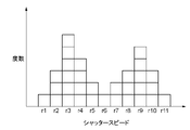
- FIG. 7 is a frequency distribution diagram of temporarily set values of the shutter speed in the imaging system according to the modified example 4.
- FIG. 8 is a block diagram of the imaging system according to the second embodiment.
- FIG. 3 is a schematic diagram, and the ratio of the size and the thickness of each component in the figure does not necessarily reflect the actual dimensional ratio.
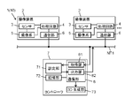
- the image pickup system 1 of the present embodiment includes a plurality of image pickup devices 2 and a controller 7.
- the controller 7 communicates with a plurality of image pickup devices 2.
- Each of the plurality of image pickup devices 2 has a reception unit 61 and an image pickup setting unit 45.
- the receiving unit 61 acquires a set value related to imaging from the controller 7.
- the image pickup setting unit 45 sets the image pickup based on the set value acquired by the reception unit 61.
- Each of the two or more image pickup devices 2 (in this embodiment, all of the plurality of image pickup devices 2) among the plurality of image pickup devices 2 has a housing 20 (see FIG. 3), a sensor 3, and a transmission unit. 62 and further.
- the sensor 3 detects the brightness outside the housing 20.
- the transmission unit 62 outputs information regarding the detection result of the sensor 3 to the controller 7.
- the controller 7 has an acquisition unit 81, a setting unit 71, and an output unit 82.
- the acquisition unit 81 acquires information regarding the detection result of each sensor 3 of the two or more image pickup devices 2.
- the setting unit 71 determines a common setting value applied to the plurality of image pickup devices 2 based on the information regarding the detection result acquired by the acquisition unit 81.
- the output unit 82 outputs the set value determined by the setting unit 71 to the plurality of image pickup devices 2.
- the imaging conditions of the plurality of imaging devices 2 can be brought close to each other.
- the properties (for example, brightness) of the plurality of images generated by the plurality of image pickup devices 2 can be brought close to each other. That is, the difference between the properties of the image generated by one of the image pickup devices 2 and the properties of the image generated by another image pickup device 2 can be made relatively small.
- the image pickup system 1 is applied to, for example, a 3D model generation system 10 (3D scanner).
- the 3D model generation system 10 generates a 3D (3Dimensions) model of the image target T1 (subject) (see FIG. 3) by using the information of a plurality of images generated by the plurality of image pickup devices 2.
- the properties of the plurality of images generated by the plurality of image pickup devices 2 become close to each other, so that a relatively high quality 3D model can be generated.
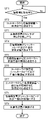
- FIG. 4 is merely an example of the operation of the imaging system 1, and the order of processing may be appropriately changed, and processing may be added or omitted as appropriate.
- the controller 7 waits for the input of the image pickup start command (step ST1).
- the image pickup start command is a command that triggers a plurality of image pickup devices 2 to take an image.
- the image pickup start command is input to the controller 7 according to the operation of the operator, for example.
- step ST1 When the image pickup start command is input to the controller 7 (step ST1: Yes), the controller 7 transmits a request signal to each of the plurality of image pickup devices 2 (step ST2).
- the information regarding the detection result of the sensor 3 is output to the controller 7. More specifically, when each of the plurality of image pickup devices 2 receives the request signal, the sensor 3 first detects the brightness (illuminance) of the outside of the housing 20 (step ST3). Next, each of the plurality of image pickup devices 2 determines a temporary setting value of the shutter speed and a temporary setting value of the F value (aperture value) based on the detected value of the brightness detected by the sensor 3 (step ST4). ).
- the temporary setting value of the shutter speed is a setting value of the shutter speed that is most suitable for the own machine when a plurality of image pickup devices 2 independently perform imaging.
- the tentative set value of the F value is the set value of the F value that is optimal for the own machine when the plurality of image pickup devices 2 independently perform imaging.
- Each of the plurality of image pickup devices 2 outputs the temporary setting value of the shutter speed and the temporary setting value of the F value to the controller 7 as information regarding the detection result of the sensor 3 (step ST5).
- the controller 7 acquires the temporary setting value of the shutter speed and the temporary setting value of the F value from each of the plurality of image pickup devices 2 (acquisition processing). That is, the controller 7 acquires a plurality of shutter speed temporary setting values that correspond one-to-one with the plurality of image pickup devices 2 and a plurality of F-number temporary setting values that correspond one-to-one with the plurality of image pickup devices 2. do.
- the controller 7 obtains the mode of the temporarily set values of the plurality of shutter speeds, and uses the obtained mode as the set value of the shutter speed (step ST6: setting process). Further, the controller 7 obtains the mode of the provisionally set value of the plurality of F values, and sets the determined mode as the set value of the F value (step ST6: setting process).
- the controller 7 transmits a setting signal including information on the set value of the shutter speed and the set value of the F value to each of the plurality of image pickup devices 2 (step ST7: output processing).
- the plurality of setting signals transmitted to the plurality of image pickup devices 2 are the same signals.
- Each of the plurality of image pickup devices 2 acquires information on the shutter speed set value and the F value set value included in the set signal. Then, each of the plurality of image pickup devices 2 adjusts the shutter speed and the F value so that the shutter speed and the F value of the own device become the set values acquired from the controller 7 (step ST8). As a result, the shutter speed is the same among the plurality of image pickup devices 2, and the F value is the same among the plurality of image pickup devices 2.
- Each of the plurality of image pickup devices 2 takes an image of the image pickup target T1 after adjusting the shutter speed and the F value (step ST9).
- the timing at which the plurality of image pickup devices 2 image the image pickup target T1 is controlled by the controller 7.
- the timing at which the plurality of image pickup devices 2 image the image pickup target T1 is, for example, simultaneous.
- each of the plurality of image pickup devices 2 images the image pickup target T1. Further, although omitted in the flowchart of FIG. 4, each of the plurality of image pickup devices 2 transmits image information (image signal) generated by imaging the image pickup target T1 to the controller 7.
- the controller 7 can generate a 3D model of the image pickup target T1 by using the information of a plurality of images acquired from the plurality of image pickup devices 2. The function of generating the 3D model may be possessed by a device other than the controller 7.
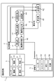
- each of the plurality of image pickup devices 2 has a sensor 3, a processing circuit 4, an image pickup system 5, and a communication unit 6.
- the sensor 3 is a two-dimensional image sensor such as a CCD (Charge Coupled Devices) image sensor or a CMOS (Complementary Metal-Oxide Semiconductor) image sensor.
- the sensor 3 is a device for detecting the brightness outside the housing 20 (see FIG. 3), and is also a device for capturing an image of the image target T1 and generating an image.
- the sensor 3 includes a plurality of pixels 31.
- the plurality of pixels 31 are arranged in a two-dimensional array. Light may be incident on each of the plurality of pixels 31 only during the exposure period.
- Each of the plurality of pixels 31 has a photoelectric conversion unit.
- the photoelectric conversion unit converts photons (incident light) into electric charges.
- the electric charge converted from the photon by the photoelectric conversion unit is output to the processing circuit 4 as an output signal in the form of a voltage.
- the imaging system 5 includes a lens 51, a shutter 52, an aperture 53, and a light source 54.
- the image pickup system 5 is mechanically controlled when the image pickup apparatus 2 takes an image of the image pickup target T1.
- the lens 51 orients light incident on the sensor 3 from the outside of the housing 20 (see FIG. 3).
- the shutter 52 opens during the exposure period of the sensor 3 to allow the incident light to pass through the sensor 3, and blocks the incident light to the sensor 3 during other periods.
- the aperture 53 adjusts the amount of light incident on the sensor 3 through the shutter 52.
- the light source 54 irradiates the image pickup target T1 when taking a flash image using the image pickup device 2. In the present embodiment, the light source 54 is not turned on, and flash photography is performed using a light source external to the image pickup apparatus 2.
- the processing circuit 4 includes a reading unit 41, an exposure calculation unit 42, a temporary setting unit 43, a storage unit 44, an image pickup setting unit 45, and an image pickup control unit 46.
- the reading unit 41, the exposure calculation unit 42, the temporary setting unit 43, the image pickup setting unit 45, and the image pickup control unit 46 merely show the functions realized by the processing circuit 4, and do not necessarily show a substantive configuration. I'm not.
- the processing circuit 4 includes a computer system having one or more processors and memories. By executing the program recorded in the memory of the computer system by the processor of the computer system, at least a part of the processing circuit 4 (specifically, the reading unit 41, the exposure calculation unit 42, the temporary setting unit 43, and the imaging setting). The functions of the unit 45 and the image pickup control unit 46) are realized.
- the program may be recorded in a memory, provided through a telecommunication line such as the Internet, or may be recorded and provided on a non-temporary recording medium such as a memory card. Further, the storage unit 44 may also serve as the memory of the processing circuit 4.
- the processing circuit 4 has a photometric mode and an image pickup mode as operation modes.
- the processing circuit 4 obtains the temporary setting value of the shutter speed and the temporary setting value of the F value based on the output signal (detection result) of the sensor 3, and the temporary setting value of the shutter speed and the temporary setting value of the F value. Is transmitted to the controller 7 via the communication unit 6.
- the processing circuit 4 In the image pickup mode, the processing circuit 4 generates an image signal including information on the image in which the image pickup target T1 is captured, based on the output signal of the sensor 3.
- the reading unit 41 reads (acquires) an output signal from a plurality of pixels 31 of the sensor 3.
- the reading unit 41 reads the output signal for the plurality of pixels 31 in a time division manner. More specifically, the reading unit 41 outputs an output signal for each of the plurality of pixels 31 arranged in a two-dimensional array at different timings for each row.
- the reading unit 41 reads the output signal from all the pixels 31 of the plurality of pixels 31 of the sensor 3. In the image pickup mode, the output signal read by the reading unit 41 is output to the controller 7 as an image signal via the communication unit 6.
- the reading unit 41 may read an output signal from some of the pixels 31 of the plurality of pixels 31 of the sensor 3. For example, in the photometric mode, the reading unit 41 may read an output signal from two or more pixels 31 located within a predetermined range including the center among the plurality of pixels 31. In the metering mode, the output signal read by the reading unit 41 is output to the exposure calculation unit 42.
- the reading unit 41 may read the output signal from all the pixels 31 of the plurality of pixels 31 of the sensor 3.
- the output signal of each of the plurality of pixels 31 read by the reading unit 41 is input to the exposure calculation unit 42. That is, in the photometric mode, a plurality of output signals are input to the exposure calculation unit 42.
- the exposure calculation unit 42 performs predetermined processing on a plurality of output signals.
- the value (hereinafter referred to as “brightness value”) obtained by the exposure calculation unit 42 by a predetermined process is a value corresponding to the external brightness of the housing 20 detected by the sensor 3.
- the predetermined process is, for example, a process of taking an average value of a plurality of output signals.
- the predetermined process may be, for example, a process in which each of the plurality of output signals is weighted and the average value of the product of each output signal and the corresponding weight is taken.
- the temporary setting unit 43 determines the temporary setting value for imaging based on the detection result of the sensor 3.
- the tentative set value corresponds to the information regarding the detection result of the sensor 3. More specifically, the temporary setting unit 43 determines the temporary setting value based on the brightness value obtained by the exposure calculation unit 42.
- the storage unit 44 of the processing circuit 4 stores a table showing the correspondence between the brightness value and the temporary setting value, and the temporary setting unit 43 determines the temporary setting value by referring to the table.
- the temporary setting unit 43 is not limited to determining the temporary setting value by referring to the table.
- the temporary setting unit 43 may obtain the temporary setting value from the brightness value by using, for example, a predetermined calculation formula.
- the temporary setting value includes the temporary setting value of the shutter speed and the temporary setting value of the F value.
- the temporary setting value of the shutter speed is a value that defines the shutter speed of the image pickup apparatus 2.
- the tentatively set value of the F value is a value that defines the F value of the image pickup apparatus 2.
- the temporary shutter speed setting value is the optimum shutter speed setting value for the own machine when a plurality of image pickup devices 2 independently perform imaging
- the F value temporary setting value is a plurality. This is the optimum F-number setting value for the own machine when the image pickup apparatus 2 of the above image is independently imaged.
- the relationship between the brightness value and each provisional setting value depends on, for example, the length of the exposure period, the sensitivity of each of the plurality of pixels 31, the size of the plurality of pixels 31, the characteristics of the lens 51, and the like.
- the temporary setting unit 43 can obtain the temporary setting value from the brightness value by appropriately referring to these information.
- the temporary setting unit 43 outputs the temporary setting value to the controller 7 via the communication unit 6 as information regarding the detection result of the sensor 3.
- the controller 7 determines the set value for imaging and outputs the set value to the plurality of image pickup devices 2.
- the image pickup setting unit 45 sets the image pickup based on the set value acquired from the controller 7.
- the set value includes a brightness setting value relating to the brightness of the image generated by the image pickup in each of the plurality of image pickup devices 2. Therefore, the settings related to imaging include settings that affect the brightness of the image generated by imaging.
- the set value includes a shutter speed setting value that defines the shutter speed of the image pickup apparatus 2 and an F value setting value that defines the F value.
- the setting related to the image pickup executed by the image pickup setting unit 45 includes the setting related to the shutter speed of the image pickup apparatus 2 and the setting related to the F value. That is, the image pickup setting unit 45 commands the image pickup control unit 46 to make the shutter speed of the image pickup device 2 equal to the shutter speed set value and the F value of the image pickup device 2 equal to the F value set value.
- the image pickup control unit 46 controls the image pickup system 5 so that the shutter speed and the F value specified by the image pickup setting unit 45 are realized.
- the communication unit 6 includes a communication interface for communicating with the controller 7.
- the communication unit 6 can communicate with the controller 7 via the communication interface.
- the term "communicable” as used in the present disclosure means that signals can be exchanged directly or indirectly via a network, a repeater, or the like by an appropriate communication method of wired communication or wireless communication.
- the communication unit 6 sends and receives signals to and from the controller 7 via the wireless communication network NT1 (see FIG. 1).
- the communication unit 6 includes a reception unit 61 and a transmission unit 62.
- the receiving unit 61 receives a signal from the controller 7.
- the transmission unit 62 transmits a signal to the controller 7.
- the receiving unit 61 and the transmitting unit 62 merely indicate the functions realized by the communication unit 6, and do not necessarily indicate a substantive configuration. Therefore, the communication interface that functions as the receiving unit 61 may also serve as the transmitting unit 62, or may be provided separately from the communication interface that functions as the transmitting unit 62.
- the controller 7 has a setting unit 71, a storage unit 72, a 3D generation unit 73, and a communication unit 8. It should be noted that the setting unit 71 and the 3D generation unit 73 merely indicate the functions realized by the controller 7, and do not necessarily indicate the actual configuration.
- Controller 7 includes a computer system having one or more processors and memory.
- the processor of the computer system executes the program recorded in the memory of the computer system, the functions of at least a part of the controller 7 (specifically, the setting unit 71 and the 3D generation unit 73) are realized.
- the program may be recorded in a memory, provided through a telecommunication line such as the Internet, or may be recorded and provided on a non-temporary recording medium such as a memory card.
- the storage unit 72 may also serve as the memory of the controller 7. At least some of the functions of the controller 7 may be realized by the server.
- the setting unit 71 acquires information on the detection result of the sensor 3 of each image pickup device 2 from a plurality of image pickup devices 2 via the communication unit 8. More specifically, the setting unit 71 acquires temporary setting values (temporary setting value of shutter speed and temporary setting value of F value) as information regarding the detection result of the sensor 3. Since the temporary setting values are output from each of the plurality of image pickup devices 2, the setting unit 71 acquires a plurality of temporary setting values of the shutter speed and a plurality of temporary setting values of the F value. The setting unit 71 determines the setting values related to the imaging of the plurality of image pickup devices 2 based on the plurality of temporary setting values.
- the setting unit 71 uses the mode value of a plurality of temporary setting values as the setting value.
- the setting unit 71 determines the set value.
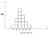
- the horizontal axis in FIG. 5 represents the temporary setting value of the shutter speed.
- Each of the ranges r1 to r6 is a range of temporary setting values of the shutter speed.
- the vertical axis of FIG. 5 represents the frequency of each of the ranges r1 to r6.
- the range r1 has a temporary setting value of 0.2 [ms] or more and less than 0.3 [ms]
- the range r2 has a temporary setting value of 0.3 [ms].
- the range and range r3 of ms] or more and less than 0.4 [ms] is a range in which the provisionally set value is 0.4 [ms] or more and less than 0.5 [ms].
- FIG. 5 represents the temporary setting value of the shutter speed.
- Each of the ranges r1 to r6 is a range of temporary setting values of the shutter speed.
- the vertical axis of FIG. 5 represents the frequency of each of the ranges r1 to r6.
- the frequency of the range r1 is 1.
- the frequencies of the ranges r2, r3, r4, r5, r6 are 3, 6, 4, 2, 1 in order.
- the mode is the value with the highest frequency.
- the setting unit 71 uses the mode value of a plurality of temporary setting values as the setting value. In FIG. 5, since the frequency of the range r3 is the largest, the setting unit 71 sets the shutter speed setting value to a value corresponding to the range r3. For example, the setting unit 71 sets a value (0.45 [ms]) between the upper limit value and the lower limit value of the range r3 as the setting value of the shutter speed.
- the horizontal axis in FIG. 6 represents the provisionally set value of the F value.
- Each of the ranges r21 to r28 is a range of the provisionally set value of the F value.
- the vertical axis of FIG. 6 represents the frequency of each of the ranges r21 to r28.
- the setting unit 71 sets the set value of the F value to the value corresponding to the range r25. For example, the setting unit 71 sets an intermediate value between the upper limit value and the lower limit value of the range r25 as the set value of the F value.
- the storage unit 72 stores various information.
- the storage unit 72 stores, for example, image information included in an image signal generated by each image pickup device 2 and transmitted to the controller 7.
- the storage unit 72 stores the identification information of each image pickup device 2 and the position information of each image pickup device 2 in association with each other. Each of the plurality of image pickup devices 2 transmits image information to the controller 7 together with the identification information of the own machine. The storage unit 72 stores the information of the image acquired from each image pickup device 2 in association with the position information of the image pickup device 2 that generated the information of the image.
- the position information of the plurality of image pickup devices 2 may be stored in advance in the storage unit 72, or may be acquired from the plurality of image pickup devices 2.
- the 3D generation unit 73 generates a 3D model of the image pickup target T1 of the plurality of image pickup devices 2 by using the information of the plurality of images generated by the plurality of image pickup devices 2.
- the 3D model generation system 10 includes at least an imaging system 1 and a 3D generation unit 73.
- the controller 7 of the image pickup system 1 has the 3D generation unit 73, but an external device of the image pickup system 1 may have the 3D generation unit 73.
- the 3D model generation system 10 of the present embodiment can generate a 3D model of a person as an image pickup target T1 (see FIG. 3), and can generate an avatar based on the generated 3D model.
- the "avatar” referred to in the present disclosure is a character displayed in virtual space as an alter ego of T1 (person) to be imaged in real space.
- the 3D model generation system 10 generates an avatar that imitates the image pickup target T1.
- the avatar is displayed in the virtual space.
- the plurality of image pickup devices 2 are installed at different positions so as to surround the image pickup target T1 and image the image pickup target T1 from different angles.
- the 3D generation unit 73 acquires information on a plurality of images (still images) that capture the image pickup target T1 from various angles.
- the 3D generation unit 73 generates a 3D model of the image pickup target T1 based on the information of a plurality of images acquired from the plurality of image pickup devices 2. Specifically, the 3D generation unit 73 calculates the coordinates of the target points in the basic space, which is a three-dimensional virtual space, for each of all the target points of all the images. Here, the 3D generation unit 73 acquires the image pickup result of each image pickup device 2 to acquire the distance from the image pickup device 2 to the target point when projected onto the basic space. Further, the 3D generation unit 73 acquires the position information of each image pickup device 2 in the real space to acquire the distance between the adjacent image pickup devices 2 when projected onto the basic space.
- the 3D generation unit 73 calculates the coordinates of the target point in the basic space based on these distances by the principle of triangulation. Then, the 3D generation unit 73 generates a 3D model of the image pickup target T1 based on the coordinates of all the target points in the basic space.
- the 3D generation unit 73 generates a texture to be attached to the 3D model based on the information of a plurality of images acquired from the plurality of image pickup devices 2.
- the texture includes a texture corresponding to the skin of the image pickup target T1 and a texture corresponding to the clothes worn by the image pickup target T1. Then, the 3D generation unit 73 pastes the generated texture on the 3D model.
- the 3D generation unit 73 executes rigging on the 3D model.
- the 3D generation unit 73 executes skeleton setting, IK (Inverse Kinematics) and / or FK (Forward Kinematics) setting, skinning including weight adjustment, and the like for the 3D model.
- IK Inverse Kinematics
- FK Forward Kinematics
- the 3D model generation system 10 captures the entire body of the image pickup target T1 with the plurality of image pickup devices 2, and the avatar of the image pickup target T1 is based on the information of the plurality of images generated. Can be automatically generated.
- the 3D model generation system 10 may acquire motion data unique to each image pickup target T1 by performing motion capture on the image pickup target T1.
- the motion data is applied to the avatar, it is possible to make the avatar move according to the motion data in the virtual space.
- the communication unit 8 includes a communication interface for communicating with a plurality of image pickup devices 2 (communication unit 6: see FIG. 1).
- the communication unit 8 can communicate with a plurality of image pickup devices 2 via a communication interface.
- the communication unit 8 sends and receives signals to and from the plurality of image pickup devices 2 via the wireless communication network NT1.
- the communication unit 8 includes an acquisition unit 81 and an output unit 82.
- the acquisition unit 81 receives signals from a plurality of image pickup devices 2.
- the output unit 82 transmits a signal to the plurality of image pickup devices 2.
- the acquisition unit 81 and the output unit 82 merely indicate the functions realized by the communication unit 8, and do not necessarily indicate a substantive configuration. Therefore, the communication interface that functions as the acquisition unit 81 may also serve as the acquisition unit 81, or may be provided separately from the communication interface that functions as the output unit 82.
- the imaging system 1 includes, for example, tens to hundreds (s) of imaging devices 2. As shown in FIG. 3, a plurality of image pickup devices 2 are embedded in the wall W1 so as to image an image pickup target T1 in a space surrounded by a cylindrical wall W1, for example.
- the wall W1 is provided with a door D1 for a person who is an image pickup target T1 to enter and exit.
- a predetermined number (6 in FIG. 3) of image pickup devices 2 are arranged in a row in the vertical direction.
- a plurality of rows consisting of a predetermined number of image pickup devices 2 are arranged so as to surround the image pickup target T1. Seen from above, the rows are arranged in a ring.
- a box 91 indicating a guideline for the position of the image pickup target T1 and an arrow 92 indicating a guideline for the direction of the image pickup target T1 are displayed.
- the wall W1 is independent of the ceiling 93. That is, the wall supporting the ceiling 93 exists separately from the wall W1. Of course, the wall W1 may support the ceiling 93.
- a plurality of (four in FIG. 3) lighting devices 94 are arranged on the ceiling 93.
- the plurality of lighting devices 94 illuminate the space SP1 imaged by the plurality of image pickup devices 2. That is, the plurality of lighting devices 94 illuminate the image pickup target T1 and the space around the image pickup target T1.
- the plurality of lighting devices 94 illuminate the space SP1 so as to suppress the unevenness of the brightness of the surface of the image pickup target T1 to a predetermined value or less.
- the embodiment of the present embodiment is not limited to the mode in which the space SP1 is illuminated from above by a plurality of lighting devices 94, and for example, the lighting device may be installed on the floor 90 and the wall W1. Further, the wall W1 may have translucency, and the space SP1 may be illuminated by a plurality of lighting devices arranged outside the wall W1.
- the operator inputs an imaging start command to the controller 7 (step ST1: Yes in FIG. 4). Then, the controller 7 starts the countdown until the start of imaging. The controller 7 notifies, for example, the number of seconds remaining until the start of imaging by voice.
- the controller 7 As a method of inputting an image pickup start command to the controller 7 by the operator, when the controller 7 has a configuration for accepting an operation of an operator such as a computer or a smartphone, the controller 7 is operated to issue an image pickup start command. You may enter it. Further, when the controller 7 is realized by the server, a terminal provided with a software application for inputting an image pickup start command to the controller 7 is separately provided, and the operator operates the terminal to start image pickup from the terminal. You may enter a command.
- the properties (for example, brightness) of the plurality of images generated by the plurality of image pickup devices 2 become close to each other, so that the quality is relatively high. 3D model can be generated.
- each of the imaging setting units 45 of the plurality of imaging devices 2 makes settings related to imaging based on the setting values acquired by the receiving unit 61.
- the set value may include a color set value relating to the color of the image generated by the image pickup in each of the plurality of image pickup devices 2.
- the color setting value may include the white balance setting value.
- the temporary setting unit 43 of each of the plurality of image pickup devices 2 determines the temporary setting value of the white balance based on the detection result of the sensor 3.
- the temporary white balance setting value is a white balance setting value that is optimal for the own device when a plurality of image pickup devices 2 independently perform imaging.
- the setting unit 71 of the controller 7 acquires a plurality of (white balance) temporary setting values from the plurality of image pickup devices 2, and sets the mode of the plurality of temporary setting values as the white balance setting value to obtain the white balance.
- the set value is transmitted to a plurality of image pickup devices 2.
- Each of the image pickup setting units 45 of the plurality of image pickup devices 2 commands the image pickup control unit 46 to make the white balance of the image pickup device 2 equal to the set value of the white balance.
- the image pickup control unit 46 performs image processing on the image signal read by the reading unit 41 so that the white balance specified by the image pickup setting unit 45 is realized. As a result, the colors of the plurality of images generated by the plurality of image pickup devices 2 can be brought close to each other.
- the set value may include an exposure set value that defines the exposure of the image pickup apparatus 2. Exposure is defined as the product of shutter speed and F-number.
- the image pickup setting unit 45 of the image pickup device 2 may determine the shutter speed and the F value so that the exposure of the image pickup device 2 becomes equal to the exposure set value.
- the image pickup control unit 46 may control the image pickup system 5 so that the shutter speed and the F value determined by the image pickup setting unit 45 are realized.
- the set value may include a gain set value that defines the gain of the image pickup apparatus 2.
- the image pickup setting unit 45 of the image pickup device 2 commands the image pickup control unit 46 to make the gain of the image pickup device 2 equal to the gain set value.
- the image pickup control unit 46 adjusts the gain so that the image signal read by the reading unit 41 is amplified by the gain specified by the image pickup setting unit 45.
- white balance adjustment is also equivalent to gain adjustment, but gain adjustment here refers to amplifying an image signal while keeping the RGB ratio constant.
- the setting unit 71 of the controller 7 uses the mode value of a plurality of temporary setting values as the setting value.
- the setting unit 71 may use the average value of a plurality of temporary setting values as the setting value.
- the setting unit 71 may use the median value of a plurality of temporary setting values as the setting value.
- the setting unit 71 may divide a plurality of temporary setting values into a plurality of ranges and use the median value of the plurality of ranges as the setting value. For example, in FIG. 6, a plurality of temporary setting values (of shutter speed) are divided into ranges r1 to r6. Since the ranges r3 and r4 are located between the ranges r1 and r6, they correspond to the median values of the ranges r1 to r6. Therefore, the setting unit 71 may set the upper limit value of the range r3 (that is, the lower limit value of the range r4) as the setting value.
- each of the plurality of image pickup devices 2 determines a temporary setting value
- the controller 7 acquires the temporary setting value from each of the plurality of image pickup devices 2.
- the controller 7 may determine the temporary setting value.
- each of the plurality of image pickup devices 2 transmits the output signal (brightness value) of the sensor 3 read by the reading unit 41 to the controller 7 as information regarding the detection result of the sensor 3. Further, each of the plurality of image pickup devices 2 transmits the identification information of the own machine and the information (first information) necessary for determining the temporary setting value to the controller 7. Further, the storage unit 72 of the controller 7 stores another information (second information) necessary for determining the temporary setting value in association with each of the plurality of image pickup devices 2. The controller 7 can determine a temporary setting value corresponding to each of the plurality of image pickup devices 2 by referring to the output signal of the sensor 3, the identification information of the image pickup device 2, the first information, and the second information.
- the information required to determine the temporary setting value includes, for example, a table showing the correspondence between the output signal (brightness value) of the sensor 3 and the temporary setting value.
- Modification example 4 It is not essential that all the image pickup devices 2 among the plurality of image pickup devices 2 transmit information regarding the detection result of the sensor 3 to the controller 7. That is, two or more image pickup devices 2 out of the plurality (all) image pickup devices 2 may transmit information regarding the detection result of each sensor 3 to the controller 7.
- the controller 7 may determine the set value based on the information regarding the detection result of the sensor 3 acquired from the two or more image pickup devices 2, and transmit the set value to all the image pickup devices 2. Even in this case, since the set values of all the image pickup devices 2 are common, the properties of the plurality of images generated by all the image pickup devices 2 can be brought close to each other.
- the temporary setting unit 43 of the two or more image pickup devices 2 may determine the temporary setting value and output the temporary setting value to the controller 7 as information regarding the detection result of the sensor 3.
- the controller 7 may group a plurality of image pickup devices 2 into a plurality of groups. Further, the setting unit 71 sets the setting value applied to one group consisting of the first number of image pickup devices 2 and information on the detection result of the sensor 3 of the second number of image pickup devices 2 belonging to the one group. It may be decided based on.
- the second number is 2 or more and less than or equal to the first number. In the present modification 5, the second number is equal to the first number. When the second number is smaller than the first number, the content of the process of determining the set value for each group is the same as that of the modified example 4.
- a plurality of groups do not partially or completely overlap. That is, it is preferable that any at least one image pickup apparatus 2 belonging to any one group belongs to only one of the plurality of groups.
- controller 7 groups, for example, a plurality of image pickup devices 2 into a plurality of groups based on the information regarding the detection result of the sensor 3.
- the controller 7 acquires a plurality of temporary setting values (of the shutter speed) from the plurality of image pickup devices 2 as information regarding the detection results of the sensor 3.
- a plurality of provisionally set values are represented in a frequency distribution diagram, as shown in FIG. 7, a plurality (two) peaks may appear for the frequency.
- peaks appear in the range r3 and the range r9.
- the controller 7 uses the image pickup device 2 belonging to the range r3 and the range in the vicinity thereof as the image pickup device 2 belonging to the first group. Further, the controller 7 uses the image pickup device 2 belonging to the range r9 and the range in the vicinity thereof as the image pickup device 2 belonging to the second group.
- the controller 7 groups, for example, a plurality of image pickup devices 2 into a first group and a second group so that the range r6 in which the dioptric power is the minimum is the boundary between the first group and the second group. Divide. That is, the controller 7 has the image pickup device 2 belonging to the range r1 to r5 as the first group, and the image pickup device 2 belonging to the range r6 to r11 as the second group.
- the image pickup apparatus 2 belonging to the range r6 may belong to the first group.
- the controller 7 may group a plurality of image pickup devices 2 into three or more groups. Further, depending on the information regarding the detection result of the sensor 3, the controller 7 may omit the process of grouping. For example, when only one peak of frequency appears, the controller 7 may omit the process of grouping.
- the setting unit 71 of the controller 7 determines the setting value corresponding to the Nth group based on two or more temporary setting values of the Nth group. For example, the setting unit 71 sets the mode of two or more temporary setting values of the Nth group as the setting value corresponding to the Nth group.
- the set value corresponding to the Nth group is transmitted to two or more image pickup devices 2 belonging to the Nth group.
- the two or more image pickup devices 2 belonging to the Nth group make settings related to imaging based on the setting values corresponding to the Nth group.
- Modification 6 is a further modification of the modification 5.
- the controller 7 groups the plurality of image pickup devices 2 into a plurality of groups based on the respective positions of the plurality of image pickup devices 2. That is, the controller 7 groups two or more image pickup devices 2 gathered in a specific area into one group.
- FIG. 3 A specific example of grouping will be described with reference to FIG.
- a predetermined number (6 in FIG. 3) of image pickup devices 2 are arranged in a row in the vertical direction.
- a plurality of rows consisting of a predetermined number of image pickup devices 2 are arranged so as to surround the image pickup target T1.
- the controller 7 groups a predetermined number of image pickup devices 2 arranged in a row into one group.
- controller 7 may group the plurality of image pickup devices 2 into a plurality of groups based on both the positions of the plurality of image pickup devices 2 and the information regarding the detection result of the sensor 3.
- the controller 7 may group a plurality of image pickup devices 2 into a plurality of groups according to the operation of the operator. For example, the operator may use two or more image pickup devices 2 arranged in the shadow as the first group and the remaining image pickup devices 2 as the second group.
- One of the plurality of image pickup devices 2 may have a function as a controller 7.
- the master may acquire information on the detection result of the sensor 3 from the remaining image pickup apparatus 2 (hereinafter referred to as “slave”), determine a set value based on the information, and transmit the information to the slave.
- two or more image pickup devices 2 out of the plurality of image pickup devices 2 may have a function as the controller 7.
- any one image pickup device 2 selected by the user may enable the function as the controller 7, and the remaining image pickup device 2 may disable the function as the controller 7. ..
- Modification 8 Functions similar to those of the imaging system 1, the 3D model generation system 10 and the controller 7 may be embodied in an imaging method, a (computer) program, a non-temporary recording medium on which the program is recorded, or the like.
- the program according to one aspect is a program for causing one or more processors (of the controller 7) to execute acquisition processing, setting processing, and output processing.
- the acquisition process is a process for acquiring information regarding the detection result of the sensor 3 for detecting the external brightness, which is possessed by each of the two or more image pickup devices 2 among the plurality of image pickup devices 2.
- the setting process is a process of determining a common setting value for imaging, which is applied to a plurality of imaging devices 2 based on the information regarding the detection result acquired in the acquisition process.
- the output process is a process of outputting the set value determined in the setting process to the plurality of image pickup devices 2.
- the imaging system 1 and the 3D model generation system 10 in the present disclosure include a computer system.
- the computer system mainly consists of a processor and a memory as hardware.
- the program may be pre-recorded in the memory of the computer system, may be provided through a telecommunications line, and may be recorded on a non-temporary recording medium such as a memory card, optical disk, hard disk drive, etc. that can be read by the computer system. May be provided.
- the processor of a computer system is composed of one or more electronic circuits including a semiconductor integrated circuit (IC) or a large scale integrated circuit (LSI).
- the integrated circuit such as IC or LSI referred to here has a different name depending on the degree of integration, and includes an integrated circuit called a system LSI, VLSI (Very Large Scale Integration), or ULSI (Ultra Large Scale Integration).
- an FPGA Field-Programmable Gate Array
- a logical device capable of reconfiguring the junction relationship inside the LSI or reconfiguring the circuit partition inside the LSI should also be adopted as a processor. Can be done.
- a plurality of electronic circuits may be integrated on one chip, or may be distributed on a plurality of chips.
- a plurality of chips may be integrated in one device, or may be distributed in a plurality of devices.
- the computer system referred to here includes a microcontroller having one or more processors and one or more memories. Therefore, the microcontroller is also composed of one or a plurality of electronic circuits including a semiconductor integrated circuit or a large-scale integrated circuit.
- the fact that a plurality of functions in the image pickup system 1 and the 3D model generation system 10 are integrated into one device is not an essential configuration for the image pickup system 1 and the 3D model generation system 10.
- the components of the image pickup system 1 and the 3D model generation system 10 may be distributed and provided in a plurality of devices. Further, at least a part of the functions of the image pickup system 1 and the 3D model generation system 10, for example, at least a part of the functions of the 3D generation unit 73 may be realized by a cloud (cloud computing) or the like.
- a plurality of image pickup devices 2 are arranged so as to surround the image pickup target T1.
- the plurality of image pickup devices 2 may be arranged side by side in a row in the horizontal direction or the vertical direction, for example, or the arrangement of the plurality of image pickup devices 2 may be non-regular.
- the image pickup system 1 it is not essential to generate a 3D model using the information of the images generated by the plurality of image pickup devices 2. No particular processing may be performed on the image information generated by the plurality of image pickup devices 2. Alternatively, a panoramic photograph may be generated by using the information of the images generated by the plurality of image pickup devices 2. That is, the image pickup system 1 may be a system in which the same subject is photographed from different angles using a plurality of image pickup devices 2 and stitched to one image.
- the plurality of image pickup devices 2 may image different image pickup targets.
- the sensor 3 for detecting the brightness of the outside of the housing 20 also serves as a device (imaging element) for imaging the image pickup target T1 and generating an image, and the image pickup element is It may be provided separately.
- the image pickup setting unit 45 of the first embodiment uses the set value acquired from the controller 7 as it is for the setting related to the image pickup.
- the image pickup setting unit 45 may correct the set value acquired from the controller 7 based on the temporary set value, and use the corrected set value for the setting related to the image pickup.
- the setting unit 71 determines the setting value related to the image pickup only once. On the other hand, the setting unit 71 may periodically determine the set value.
- the image pickup apparatus 2 sets the image pickup independently from the controller 7, sets the image pickup target T1 independently, and sets the image pickup target T1 based on the set value acquired from the controller 7. May have a coordinated mode for imaging.
- the operation of the image pickup apparatus 2 described in the first embodiment corresponds to the operation in the cooperative mode.
- the controller 7 may be provided separately from the plurality of image pickup devices 2.
- the setting unit 71 of the controller 7 may determine the set value based on additional information in addition to the information regarding the detection result of each sensor 3 of at least a part of the image pickup devices 2 among the plurality of image pickup devices 2. ..
- additional image pickup device in which the image pickup is not set by the setting unit 71 is installed, and the setting unit 71 further sets a set value based on the information regarding the detection result (brightness detection result) of the sensor of the additional image pickup device. You may decide.
- the controller 7A of the imaging system 1A has a brightness adjusting unit 74 instead of the setting unit 71 (see FIG. 1). Further, the controller 7A has a second communication unit 75 in addition to the communication unit 8 (referred to as “first communication unit 8” in the present embodiment).
- first communication unit 8 the communication unit 8
- the configuration of the communication unit 8, the storage unit 72, and the 3D generation unit 73, and the configuration of each image pickup device 2 are the same as those of the first embodiment.
- the brightness adjusting unit 74 merely shows the function realized by the controller 7A, and does not necessarily show the actual configuration.
- the second communication unit 75 includes a communication interface for communicating with a plurality of lighting devices 94.
- the second communication unit 75 can communicate with a plurality of lighting devices 94 via a communication interface.
- the second communication unit 75 sends and receives signals to and from the plurality of lighting devices 94 via the wireless communication network NT2.
- the first communication unit 8 may also serve as the second communication unit 75.
- the wireless communication network NT1 may also serve as the wireless communication network NT2.
- the controller 7A of the present embodiment does not execute the process of determining the set value for the image pickup of the plurality of image pickup devices 2. For example, the operator may input the set value appropriately determined by the operator to the controller 7A, and the controller 7A may transmit the input set value to the plurality of image pickup devices 2.
- the controller 7A adjusts the brightness of each of the plurality of lighting devices 94 that illuminate the space imaged by the plurality of image pickup devices 2. More specifically, the acquisition unit 81 detects the output signal of the sensor 3 (signal relating to the brightness outside the housing 20) read by the reading unit 41 from each of the plurality of image pickup devices 2. Get as information about the result. The brightness adjustment unit 74 adjusts the brightness of each of the plurality of lighting devices 94 based on the information regarding the detection result of the sensor 3 acquired by the acquisition unit 81. The brightness adjusting unit 74 adjusts the brightness of each of the plurality of lighting devices 94 by transmitting control signals to the plurality of lighting devices 94 via the second communication unit 75.
- the target (brightness value) detected by the sensor 3 is the illuminance
- the target adjusted by the brightness adjusting unit 74 is the brightness of each of the plurality of lighting devices 94.
- the brightness adjusting unit 74 adjusts at least one of the overall brightness of the plurality of lighting devices 94 and the ratio of the brightness.
- the brightness adjusting unit 74 adjusts the overall brightness of the plurality of lighting devices 94.
- a plurality of brightness adjusting units 74 are used so that the ratio of the brightness of the plurality of lighting devices 94 is kept constant, or the amount of change in brightness is the same among the plurality of lighting devices 94.
- the brightness of the lighting device 94 is adjusted.
- the brightness adjustment unit 74 acquires the output signal (brightness value) of each sensor 3 of the plurality of image pickup devices 2 via the acquisition unit 81. That is, the brightness adjustment unit 74 acquires a plurality of brightness values that correspond one-to-one with the plurality of image pickup devices 2.
- the brightness adjusting unit 74 obtains, for example, the average value of a plurality of brightness values, and compares the average value with the first threshold value and the second threshold value. The second threshold is larger than the first threshold. When the average value is less than the first threshold value, the brightness adjusting unit 74 brightens the brightness of each of the plurality of lighting devices 94.
- the brightness adjusting unit 74 darkens the brightness of each of the plurality of lighting devices 94.
- the brightness of the images generated by the plurality of image pickup devices 2 can be adjusted within a predetermined range.
- the brightness adjustment unit 74 acquires the brightness value and the identification information of the image pickup device 2 from each of the plurality of image pickup devices 2. That is, the brightness adjusting unit 74 acquires a plurality of brightness values and a plurality of identification information corresponding to the plurality of brightness values on a one-to-one basis. Further, the brightness adjusting unit 74 acquires the position information of the plurality of image pickup devices 2 and the position information of the plurality of lighting devices 94 from the storage unit 72.
- the position information of the plurality of image pickup devices 2 may be stored in advance in the storage unit 72, or may be acquired from the plurality of image pickup devices 2.
- the position information of the plurality of lighting devices 94 may be stored in advance in the storage unit 72, or may be acquired from the plurality of lighting devices 94.
- the storage unit 72 includes linking information for associating the plurality of image pickup devices 2 with the plurality of lighting devices 94.
- Each image pickup device 2 is associated with a lighting device 94 located near the image pickup device 2.
- the association information may be generated by the controller 7A based on the position information of the plurality of image pickup devices 2 and the position information of the plurality of lighting devices 94, or may be stored in advance in the storage unit 72.
- the brightness adjustment unit 74 adjusts the brightness of the plurality of lighting devices 94 based on the ratio of the plurality of brightness values. For example, when the brightness value acquired from a certain image pickup device 2 is larger than a predetermined value as compared with the average value of a plurality of brightness values, the brightness adjustment unit 74 is associated with the image pickup device 2 ( That is, the brightness of the lighting device 94 (located near the image pickup device 2) is dimmed. Further, when the brightness value acquired from a certain image pickup device 2 is smaller than a predetermined value as compared with the average value of a plurality of brightness values, the brightness adjustment unit 74 has an illumination associated with the image pickup device 2. Brighten the brightness of the device 94. In order to generate a 3D model of the image pickup target T1, it is preferable that the variation in the plurality of brightness values acquired from the plurality of image pickup devices 2 is small.
- the brightness adjusting unit 74 adjusts the brightness of the plurality of lighting devices 94 to obtain the quality (brightness) of a plurality of images generated by the plurality of image pickup devices 2. It can be improved, and the properties of the plurality of images generated by the plurality of image pickup devices 2 can be brought close to each other.
- the brightness adjustment unit 74 may adjust the brightness of each of the plurality of lighting devices 94 based on the provisional setting values determined by each of the plurality of image pickup devices 2.
- the controller 7A may have a setting unit 71 (see FIG. 1). That is, in addition to the process of adjusting the brightness of each of the plurality of lighting devices 94, the controller 7A may also perform a process of determining a set value for imaging of the plurality of image pickup devices 2.
- the image pickup system (1, 1A) includes a plurality of image pickup devices (2) and a controller (7, 7A).
- the controller (7, 7A) communicates with a plurality of image pickup devices (2).
- Each of the plurality of image pickup devices (2) has a reception unit (61) and an image pickup setting unit (45).
- the receiving unit (61) acquires set values related to imaging from the controller (7, 7A).
- the image pickup setting unit (45) makes settings related to image pickup based on the setting values acquired by the reception unit (61).
- Each of the two or more image pickup devices (2) out of the plurality of image pickup devices (2) further includes a housing (20), a sensor (3), and a transmission unit (62).
- the sensor (3) detects the brightness outside the housing (20).
- the transmission unit (62) outputs information regarding the detection result of the sensor (3) to the controller (7, 7A).
- the controller (7, 7A) has an acquisition unit (81), a setting unit (71), and an output unit (82).
- the acquisition unit (81) acquires information regarding the detection result of each sensor (3) of the two or more image pickup devices (2).
- the setting unit (71) determines a common setting value applied to the plurality of image pickup devices (2) based on the information regarding the detection result acquired by the acquisition unit (81).
- the output unit (82) outputs the set value determined by the setting unit (71) to the plurality of image pickup devices (2).
- the imaging conditions of the plurality of imaging devices (2) can be brought close to each other.
- the properties (brightness, color, etc.) of the plurality of images generated by the plurality of image pickup devices (2) can be brought close to each other. That is, the difference between the properties of the image generated by one of the image pickup devices (2) and the properties of the image generated by another image pickup device (2) can be made relatively small.
- the set value is the brightness setting relating to the brightness of the image generated by the image pickup in each of the plurality of image pickup devices (2). Includes a value.
- the brightness of a plurality of images generated by the plurality of image pickup devices (2) can be made close to each other.
- the set value is a color setting relating to the color of the image generated by the image pickup in each of the plurality of image pickup devices (2). Includes a value.
- the colors of a plurality of images generated by the plurality of image pickup devices (2) can be brought close to each other.
- each of the two or more image pickup devices (2) is a temporary setting unit (43). Further has.
- the temporary setting unit (43) determines a temporary setting value for imaging as information regarding the detection result of the sensor (3) based on the detection result of the sensor (3).
- the setting unit (71) of the controller (7, 7A) determines the set value based on the temporary setting value determined by the temporary setting unit (43) of each of the two or more image pickup devices (2).
- the setting unit (71) of the controller (7, 7A) is each of the two or more image pickup devices (2).
- the mode of the temporary setting value determined by the temporary setting unit (43) is set as the set value.
- the setting unit (71) of the controller (7, 7A) is each of the two or more image pickup devices (2).
- the average value of the temporary setting values determined by the temporary setting unit (43) is used as the set value.
- the controller (7, 7A) has a plurality of image pickup devices (2) in a plurality of groups. Group into groups.
- the setting unit (71) sets the setting value applied to one group consisting of the first number of image pickup devices (2) to the sensor (3) of the second number of image pickup devices (2) belonging to the one group. ) Is determined based on the information regarding the detection result.
- the second number is 2 or more and less than or equal to the first number.
- an appropriate setting value can be determined for each group.
- each of the plurality of image pickup devices (2) has a sensor (3) and a transmission unit (62).
- the controller (7, 7A) groups the plurality of image pickup devices (2) into a plurality of groups based on the information regarding the detection result of the sensor (3).
- the controller (7, 7A) has a plurality of image pickup devices (2) and each of the plurality of image pickup devices (2). Group into multiple groups based on location.
- an appropriate set value can be determined for each image pickup device (2).
- the controller (7, 7A) further has a brightness adjusting unit (74).
- the brightness adjustment unit (74) acquires the brightness adjustment of each of the plurality of lighting devices (94) that illuminate the space (SP1) imaged by the plurality of image pickup devices (2) by the acquisition unit (81). This is done based on the information about the detection result.
- the space (SP1) imaged by the plurality of image pickup devices (2) can be made to an appropriate brightness.
- the properties of the plurality of images generated by the plurality of image pickup devices (2) can be brought close to each other.
- the image pickup system (1, 1A) includes a plurality of image pickup devices (2) and a controller (7, 7A).
- the controller (7, 7A) communicates with a plurality of image pickup devices (2).
- Each of the two or more image pickup devices (2) out of the plurality of image pickup devices (2) has a housing (20), a sensor (3), and a transmission unit (62).
- the sensor (3) detects the brightness outside the housing (20).
- the transmission unit (62) outputs information regarding the detection result of the sensor (3) to the controller (7, 7A).
- the controller (7, 7A) has an acquisition unit (81) and a brightness adjustment unit (74).
- the acquisition unit (81) acquires information regarding the detection result of each sensor (3) of the two or more image pickup devices (2).
- the brightness adjustment unit (74) acquires the brightness adjustment of each of the plurality of lighting devices (94) that illuminate the space (SP1) imaged by the plurality of image pickup devices (2) by the acquisition unit (81). This is done based on the information about the detection result.
- the space (SP1) imaged by the plurality of image pickup devices (2) can be made to an appropriate brightness.
- the properties of the plurality of images generated by the plurality of image pickup devices (2) can be brought close to each other.
- Configurations other than the first or eleventh aspects are not essential configurations for the imaging system (1, 1A) and can be omitted as appropriate.
- the 3D model generation system (10, 10A) includes an imaging system (1, 1A) and a 3D generation unit (73) according to any one of the first to eleventh aspects. Be prepared.
- the 3D generation unit (73) uses the information of the plurality of images generated by the plurality of image pickup devices (2) of the image pickup system (1, 1A) to obtain the image pickup target (T1) of the plurality of image pickup devices (2). Generate a 3D model.
- the quality of the 3D model can be improved.
- the controller (7, 7A) has an acquisition unit (81), a setting unit (71), and an output unit (82).
- the acquisition unit (81) acquires information on the detection result of the sensor (3) for detecting the external brightness, which is possessed by each of the two or more image pickup devices (2) among the plurality of image pickup devices (2).
- the setting unit (71) determines a common setting value for imaging applied to the plurality of image pickup devices (2) based on the information regarding the detection result acquired by the acquisition unit (81).
- the output unit (82) outputs the set value determined by the setting unit (71) to the plurality of image pickup devices (2).
- the properties (brightness, color, etc.) of a plurality of images generated by the plurality of image pickup devices (2) can be brought close to each other.
- the program according to the fourteenth aspect is a program for causing one or more processors to execute acquisition processing, setting processing, and output processing.
- the acquisition process is a process of acquiring information regarding the detection result of the sensor (3) for detecting the external brightness, which is possessed by each of two or more image pickup devices (2) among the plurality of image pickup devices (2).
- the setting process is a process of determining a common setting value for imaging, which is applied to a plurality of imaging devices (2), based on the information regarding the detection result acquired in the acquisition process.
- the output process is a process of outputting the set value determined in the setting process to a plurality of image pickup devices (2).
- the properties (brightness, color, etc.) of a plurality of images generated by the plurality of image pickup devices (2) can be brought close to each other.
- various configurations (including modifications) of the imaging system (1, 1A) and the 3D model generation system (10, 10A) according to the embodiment can be embodied by methods and programs.
- Imaging system 2 Imaging device 3 Sensor 7, 7A Controller 10, 10A 3D model generation system 20 Housing 43 Temporary setting unit 45 Imaging setting unit 61 Receiver 62 Transmission unit 71 Setting unit 73 3D generation unit 74 Brightness adjustment unit 81 Acquisition unit 82 Output unit 94 Lighting device T1 Image capture target
Landscapes
- Engineering & Computer Science (AREA)
- Multimedia (AREA)
- Signal Processing (AREA)
- Physics & Mathematics (AREA)
- General Physics & Mathematics (AREA)
- Human Computer Interaction (AREA)
- Studio Devices (AREA)
Priority Applications (2)
| Application Number | Priority Date | Filing Date | Title |
|---|---|---|---|
| JP2022560768A JPWO2022097613A1 (https=) | 2020-11-04 | 2021-11-02 | |
| US18/308,296 US20230269464A1 (en) | 2020-11-04 | 2023-04-27 | Imaging system, 3d model generation system, controller, and method |
Applications Claiming Priority (2)
| Application Number | Priority Date | Filing Date | Title |
|---|---|---|---|
| JP2020184682 | 2020-11-04 | ||
| JP2020-184682 | 2020-11-04 |
Related Child Applications (1)
| Application Number | Title | Priority Date | Filing Date |
|---|---|---|---|
| US18/308,296 Continuation US20230269464A1 (en) | 2020-11-04 | 2023-04-27 | Imaging system, 3d model generation system, controller, and method |
Publications (1)
| Publication Number | Publication Date |
|---|---|
| WO2022097613A1 true WO2022097613A1 (ja) | 2022-05-12 |
Family
ID=81457900
Family Applications (1)
| Application Number | Title | Priority Date | Filing Date |
|---|---|---|---|
| PCT/JP2021/040319 Ceased WO2022097613A1 (ja) | 2020-11-04 | 2021-11-02 | 撮像システム、3dモデル生成システム、コントローラ、方法及びプログラム |
Country Status (3)
| Country | Link |
|---|---|
| US (1) | US20230269464A1 (https=) |
| JP (1) | JPWO2022097613A1 (https=) |
| WO (1) | WO2022097613A1 (https=) |
Citations (4)
| Publication number | Priority date | Publication date | Assignee | Title |
|---|---|---|---|---|
| JP2001320616A (ja) * | 2000-02-29 | 2001-11-16 | Matsushita Electric Ind Co Ltd | 撮像システム |
| JP2006217357A (ja) * | 2005-02-04 | 2006-08-17 | Olympus Corp | デジタルカメラシステム |
| WO2017154606A1 (ja) * | 2016-03-10 | 2017-09-14 | ソニー株式会社 | 情報処理装置および情報処理方法 |
| JP2018037739A (ja) * | 2016-08-29 | 2018-03-08 | 京セラ株式会社 | 画像処理装置、画像処理システム、移動体、及び画像処理方法 |
-
2021
- 2021-11-02 JP JP2022560768A patent/JPWO2022097613A1/ja active Pending
- 2021-11-02 WO PCT/JP2021/040319 patent/WO2022097613A1/ja not_active Ceased
-
2023
- 2023-04-27 US US18/308,296 patent/US20230269464A1/en active Pending
Patent Citations (4)
| Publication number | Priority date | Publication date | Assignee | Title |
|---|---|---|---|---|
| JP2001320616A (ja) * | 2000-02-29 | 2001-11-16 | Matsushita Electric Ind Co Ltd | 撮像システム |
| JP2006217357A (ja) * | 2005-02-04 | 2006-08-17 | Olympus Corp | デジタルカメラシステム |
| WO2017154606A1 (ja) * | 2016-03-10 | 2017-09-14 | ソニー株式会社 | 情報処理装置および情報処理方法 |
| JP2018037739A (ja) * | 2016-08-29 | 2018-03-08 | 京セラ株式会社 | 画像処理装置、画像処理システム、移動体、及び画像処理方法 |
Also Published As
| Publication number | Publication date |
|---|---|
| US20230269464A1 (en) | 2023-08-24 |
| JPWO2022097613A1 (https=) | 2022-05-12 |
Similar Documents
| Publication | Publication Date | Title |
|---|---|---|
| US10931897B2 (en) | Systems and methods for a digital image sensor | |
| US11461910B2 (en) | Electronic device for blurring image obtained by combining plural images based on depth information and method for driving the electronic device | |
| JP7318953B2 (ja) | マルチカメラ画像処理 | |
| JP7179461B2 (ja) | フラッシュ照明画像および周囲照明画像を同時に捕捉するための画像センサ装置および方法 | |
| CN116017164A (zh) | 捕获并生成全景三维图像的系统和方法 | |
| US20130201288A1 (en) | High dynamic range & depth of field depth camera | |
| EP3507765A1 (en) | Systems and methods for adjusting focus based on focus target information | |
| JP2018503325A (ja) | 画素データに対して演算を実行するためのシステムおよび方法 | |
| CN110636227B (zh) | 高动态范围hdr图像合成方法及集成该方法的高速相机 | |
| CN103905731B (zh) | 一种宽动态图像采集方法及系统 | |
| JP2010504664A (ja) | モノクロカメラでカラーイメージを撮影する結像方法と装置 | |
| CN110463183A (zh) | 识别装置及方法 | |
| CN109672827A (zh) | 用于组合多个图像的电子装置及其方法 | |
| CN113472988A (zh) | 一种高速线阵相机和高强度光源同步触发控制的图像采集方法及其装置 | |
| TWI684165B (zh) | 影像處理方法與電子裝置 | |
| CN112840644A (zh) | 利用相机或深度传感器中的至少一个获取深度信息的电子装置和方法 | |
| CN112565733B (zh) | 基于多相机同步拍摄的三维成像方法、装置及拍摄系统 | |
| CN102857681A (zh) | 一种通过半反射镜采集图像和提高图像质量的方法 | |
| CN102202182B (zh) | 一种采用线阵ccd的大动态范围图像获取的装置及方法 | |
| CN115278098B (zh) | 图像拍摄的方法、系统及其拍摄装置 | |
| JP2004328657A (ja) | 画像入力装置、画像入力方法およびプログラム | |
| WO2022097613A1 (ja) | 撮像システム、3dモデル生成システム、コントローラ、方法及びプログラム | |
| CN115802170A (zh) | 图像输出方法、图像传感器及图像输出系统 | |
| KR20150125246A (ko) | 다시점 카메라에 대한 촬영 설정값을 조절하는 방법 및 다시점 카메라에 대한 촬영 설정값을 조절하는 장치 | |
| US20240323335A1 (en) | Light capture device and light capture system including same |
Legal Events
| Date | Code | Title | Description |
|---|---|---|---|
| 121 | Ep: the epo has been informed by wipo that ep was designated in this application |
Ref document number: 21889166 Country of ref document: EP Kind code of ref document: A1 |
|
| ENP | Entry into the national phase |
Ref document number: 2022560768 Country of ref document: JP Kind code of ref document: A |
|
| NENP | Non-entry into the national phase |
Ref country code: DE |
|
| 122 | Ep: pct application non-entry in european phase |
Ref document number: 21889166 Country of ref document: EP Kind code of ref document: A1 |