WO2022097564A1 - インサートおよび切削工具 - Google Patents
インサートおよび切削工具 Download PDFInfo
- Publication number
- WO2022097564A1 WO2022097564A1 PCT/JP2021/039811 JP2021039811W WO2022097564A1 WO 2022097564 A1 WO2022097564 A1 WO 2022097564A1 JP 2021039811 W JP2021039811 W JP 2021039811W WO 2022097564 A1 WO2022097564 A1 WO 2022097564A1
- Authority
- WO
- WIPO (PCT)
- Prior art keywords
- groove
- insert
- cutting edge
- length
- end portion
- Prior art date
- Legal status (The legal status is an assumption and is not a legal conclusion. Google has not performed a legal analysis and makes no representation as to the accuracy of the status listed.)
- Ceased
Links
Images


Classifications
-
- B—PERFORMING OPERATIONS; TRANSPORTING
- B23—MACHINE TOOLS; METAL-WORKING NOT OTHERWISE PROVIDED FOR
- B23B—TURNING; BORING
- B23B27/00—Tools for turning or boring machines; Tools of a similar kind in general; Accessories therefor
- B23B27/14—Cutting tools of which the bits or tips or cutting inserts are of special material
- B23B27/141—Specially shaped plate-like cutting inserts, i.e. length greater or equal to width, width greater than or equal to thickness
- B23B27/145—Specially shaped plate-like cutting inserts, i.e. length greater or equal to width, width greater than or equal to thickness characterised by having a special shape
-
- B—PERFORMING OPERATIONS; TRANSPORTING
- B23—MACHINE TOOLS; METAL-WORKING NOT OTHERWISE PROVIDED FOR
- B23B—TURNING; BORING
- B23B27/00—Tools for turning or boring machines; Tools of a similar kind in general; Accessories therefor
- B23B27/10—Cutting tools with special provision for cooling
-
- B—PERFORMING OPERATIONS; TRANSPORTING
- B23—MACHINE TOOLS; METAL-WORKING NOT OTHERWISE PROVIDED FOR
- B23B—TURNING; BORING
- B23B27/00—Tools for turning or boring machines; Tools of a similar kind in general; Accessories therefor
- B23B27/14—Cutting tools of which the bits or tips or cutting inserts are of special material
- B23B27/16—Cutting tools of which the bits or tips or cutting inserts are of special material with exchangeable cutting bits or cutting inserts, e.g. able to be clamped
- B23B27/1603—Cutting tools of which the bits or tips or cutting inserts are of special material with exchangeable cutting bits or cutting inserts, e.g. able to be clamped with specially shaped plate-like exchangeable cutting inserts, e.g. chip-breaking groove
- B23B27/1611—Cutting tools of which the bits or tips or cutting inserts are of special material with exchangeable cutting bits or cutting inserts, e.g. able to be clamped with specially shaped plate-like exchangeable cutting inserts, e.g. chip-breaking groove characterised by having a special shape
-
- B—PERFORMING OPERATIONS; TRANSPORTING
- B23—MACHINE TOOLS; METAL-WORKING NOT OTHERWISE PROVIDED FOR
- B23C—MILLING
- B23C5/00—Milling-cutters
- B23C5/28—Features relating to lubricating or cooling
-
- B—PERFORMING OPERATIONS; TRANSPORTING
- B23—MACHINE TOOLS; METAL-WORKING NOT OTHERWISE PROVIDED FOR
- B23B—TURNING; BORING
- B23B2200/00—Details of cutting inserts
- B23B2200/04—Overall shape
- B23B2200/0471—Square
- B23B2200/0476—Square rounded
-
- B—PERFORMING OPERATIONS; TRANSPORTING
- B23—MACHINE TOOLS; METAL-WORKING NOT OTHERWISE PROVIDED FOR
- B23B—TURNING; BORING
- B23B2200/00—Details of cutting inserts
- B23B2200/08—Rake or top surfaces
- B23B2200/086—Rake or top surfaces with one or more grooves
-
- B—PERFORMING OPERATIONS; TRANSPORTING
- B23—MACHINE TOOLS; METAL-WORKING NOT OTHERWISE PROVIDED FOR
- B23B—TURNING; BORING
- B23B2200/00—Details of cutting inserts
- B23B2200/20—Top or side views of the cutting edge
- B23B2200/201—Details of the nose radius and immediately surrounding area
-
- B—PERFORMING OPERATIONS; TRANSPORTING
- B23—MACHINE TOOLS; METAL-WORKING NOT OTHERWISE PROVIDED FOR
- B23B—TURNING; BORING
- B23B2222/00—Materials of tools or workpieces composed of metals, alloys or metal matrices
- B23B2222/28—Details of hard metal, i.e. cemented carbide
-
- B—PERFORMING OPERATIONS; TRANSPORTING
- B23—MACHINE TOOLS; METAL-WORKING NOT OTHERWISE PROVIDED FOR
- B23B—TURNING; BORING
- B23B2250/00—Compensating adverse effects during turning, boring or drilling
- B23B2250/12—Cooling and lubrication
- B23B2250/121—Insert with coolant channels
-
- B—PERFORMING OPERATIONS; TRANSPORTING
- B23—MACHINE TOOLS; METAL-WORKING NOT OTHERWISE PROVIDED FOR
- B23B—TURNING; BORING
- B23B2250/00—Compensating adverse effects during turning, boring or drilling
- B23B2250/12—Cooling and lubrication
- B23B2250/124—Coolant trapping reservoir, e.g. recesses, pockets on external surface of tool
-
- B—PERFORMING OPERATIONS; TRANSPORTING
- B23—MACHINE TOOLS; METAL-WORKING NOT OTHERWISE PROVIDED FOR
- B23C—MILLING
- B23C2200/00—Details of milling cutting inserts
- B23C2200/08—Rake or top surfaces
- B23C2200/086—Rake or top surfaces with one or more grooves
Definitions
- This disclosure relates to inserts and cutting tools.
- Cemented carbide, cermet, and ceramics are used as inserts for cutting tools because they are materials with excellent heat resistance and wear resistance. Since the insert comes into contact with the work material at high speed during use, the temperature rises.
- Patent Document 1 provides a plurality of grooves functioning as a flow path for the coolant on the rake face of the insert. Further, in Japanese Patent No. 4275856 (Patent Document 2), the groove provided on the upper surface has a constant groove depth.
- the insert of the present disclosure has a first surface, a second surface connected to the first surface, and a cutting edge located at least a part of the ridgeline of the first surface and the second surface.
- the first surface has a groove extending from the first end closest to the cutting edge toward the second end farthest from the cutting edge at a position away from the ridgeline.
- the groove has an opening located on the first surface and a bottom surface. When the distance from the bottom surface to the opening is defined as the groove depth and the groove length in the extending direction of the groove is defined as the groove length, the groove is located at a position closer to the first end than half of the groove length, and is the second. It has a first groove portion in which the groove depth increases from the end portion to the first end portion, and a second groove portion in which the groove depth decreases toward the first end portion from the second end portion. The first groove is located closer to the second end than the second groove.
- the cutting tool of the present disclosure has a length extending from the first end to the second end, and has a holder having a pocket located on the side of the first end and the above-mentioned insert located in the pocket.
- FIG. It is a perspective view which shows an example of the insert of this disclosure. It is a top view of the insert shown in FIG. It is an enlarged view in the vicinity of the corner portion in the insert shown in FIG. It is sectional drawing of the IV-IV cross section in the insert shown in FIG. It is the same sectional view as FIG. It is a perspective view which shows an example of the insert of this disclosure. It is a top view of the insert shown in FIG. It is a perspective view which shows an example of the insert of this disclosure. It is a top view of the insert shown in FIG. It is a perspective view which shows an example of the insert of this disclosure. It is a top view of the insert shown in FIG. It is a perspective view which shows an example of the insert of this disclosure. It is a top view of the insert shown in FIG. It is a top view which shows an example of the cutting tool of this disclosure. It is a top view which shows an example of the cutting tool of this disclosure.
- the conventional insert cannot provide a cooling effect that can sufficiently contribute to increasing the cutting speed.
- the present disclosure provides inserts and cutting tools that can provide a cooling effect that can sufficiently contribute to higher cutting speeds.
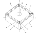
- the insert 1 shown in FIGS. 1 to 5 is an example of a cutting insert with a replaceable cutting edge, which is attached to a predetermined position at the tip of a holder (not shown) and used.
- the insert 1 may be paraphrased as a cutting insert 1.
- the insert 1 may have a substrate 3 made of cemented carbide, cermet, or the like.
- the insert 1 may include a substrate 3 made of a so-called cemented carbide containing WC and Co, Ni, and Fe which are bonding phases. When such a substrate 3 is used, it is excellent in welding resistance to a metal containing Ti.
- the WC is WC particles.
- the WC particles may have, for example, an average particle size of 0.5 ⁇ m to 1.5 ⁇ m.
- the substrate 3 may contain 4 to 12% by mass of the bound phase.
- the substrate 3 may have only WC as the balance other than the bound phase.
- the substrate 3 may contain a hard phase containing WC and a bound phase containing Co. In the present disclosure, when the range is indicated, such as 4 to 12% by mass, it means the value of the lower limit or more and the value of the upper limit or less.
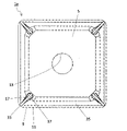
- the insert 1 may have a polygonal plate shape, and may have a first surface 5 and a second surface 7 connected to the first surface 5. Further, the insert 1 may have a square shape when the first surface 5 is viewed in a plan view.
- the insert 1 may have a cutting edge 11 located at least a part of the ridge line 9 of the first surface 5 and the second surface 7.
- the first surface 5 corresponds to the rake surface 5, and the second surface 7 corresponds to the flank surface 7.
- the first surface 5 may be provided with a through hole 13 that vertically penetrates the insert 1 in order to fix the insert 1 to a holder described later.
- the cutting edge 11 may be located at least in a part of the ridge line 9, may be located in a portion corresponding to two sides, and may be located in an annular shape over the entire outer peripheral portion of the first surface 5. May be.
- the insert 1 may have a third surface 15 located on the opposite side of the first surface 5.
- the first surface 5 is called the “upper surface”
- the second surface 7 is called the “side surface”
- the third surface 15 is called the “lower surface”.
- the size of the insert 1 is not particularly limited, but for example, the length of one side of the first surface 5 is set to about 5 to 20 mm, and the height from the first surface 5 to the third surface 15 is set. It is set to about 3 to 20 mm.
- the first surface 5 may have a groove 17.
- the groove 17 can function as a flow path for the coolant.
- the number of grooves 17 may be one or a plurality.
- the groove 17 may extend from the first end portion 17a closest to the cutting edge 11 toward the second end portion 17b farthest from the cutting edge 11 at a position away from the ridge line 9. With such a configuration, since the groove 17 is not connected to the ridge line 9, the cutting edge 11 is excellent in fracture resistance.
- the groove 17 may be separated from the ridge line 9 within a range of 40 ⁇ m or more and 700 ⁇ m or less from the ridge line 9.
- the distance between the groove 17 and the ridge line 9 may be 40 ⁇ m or more and 700 ⁇ m or less.
- the cutting edge 11 is less likely to be damaged.
- the distance between the groove 17 and the ridge line 9 is 700 ⁇ m or less, the cooling effect of the cutting edge 11 is enhanced, and the cutting resistance is easily reduced.
- the distance between the groove 17 and the ridge line 9 may be 50 ⁇ m or more and 120 ⁇ m or less. With such a configuration, the cutting edge 11 of the insert 1 is less likely to be damaged, and the cutting resistance is small. As the distance between the groove 17 and the ridge line 9, the shortest distance between the groove 17 and the ridge line 9 may be measured.
- the groove 17 may have an opening 19 located on the first surface 5 and a bottom surface 21.
- the distance from the bottom surface 21 to the opening 19 may be the groove depth D.
- the groove depth D may be defined as follows. First, a virtual straight line passing through the center of the first surface 5 and the center of the third surface 15 may be used as the central axis O of the insert 1. Next, a virtual plane orthogonal to the central axis O and located between the first surface 5 and the third surface 15 may be used as the reference surface S. Then, the dimension between the bottom surface 21 and the opening 19 in the virtual straight line L1 orthogonal to the reference plane S may be the groove depth D.
- the length of the groove 17 in the extending direction of the groove 17 may be the groove length L.
- the groove 17 may have a first groove portion 23 and a second groove portion 25 at a position closer to the first end portion 17a than half (midpoint) of the groove length L.
- the groove depth D of the first groove portion 23 may increase from the second end portion 17b toward the first end portion 17a.
- the groove depth D of the second groove portion 25 may decrease from the second end portion 17b toward the first end portion 17a.
- the first groove portion 23 may be located closer to the second end portion 17b than the second groove portion 25.
- the groove 17 becomes a flow path for the coolant, and the coolant is supplied in the order of the first groove 23 and the second groove 25 in the vicinity of the cutting edge. Can be shed. Then, the groove 17 in the vicinity of the cutting edge can be deepened by the first groove portion 23 and the second groove portion 25, and the depth of the groove 17 can be changed in the vicinity of the cutting edge.
- the groove 17 in the vicinity of the cutting edge it is possible to increase the contact area with the coolant and enhance the cooling effect in the vicinity of the cutting edge. Further, by changing the depth of the groove 17 in the vicinity of the cutting edge, it is possible to generate turbulent flow of the coolant and improve the heat exchange efficiency. Therefore, since the insert 1 has excellent cooling performance, it can be cut at high speed.
- FIG. 4 shows an example in which the first surface 5 is flat and the opening 19 is also on the flat first surface 5.
- the first surface 5 may be higher on the cutting edge 11 side.
- the cutting speed (Vc) is 60 to 100 m / min
- the feed rate (f) is 0.05 to 0.3 mm / rev
- the cutting (cutting) ( ap) can be set to 0.2 to 2.0 mm.
- Vc it is possible to set Vc to 80 m / min, f to 0.1 mm / rev, and ap to 0.5 mm.
- Vc 100 m / min, f to 0.15 mm / rev, and ap to 0.5 mm.
- the work material is SCM435, it is possible to set Vc to 250 m / min, f to 0.3 mm / rev, and ap to 2.0 mm.
- the groove depth D and the groove length L are not limited to specific values.
- the groove depth D may be set to about 40 ⁇ m or more and 700 ⁇ m or less.
- the groove length L may be set to about 40 ⁇ m or more and 5000 ⁇ m or less.
- the second groove portion 25 may exist within a range of 1/5 of the groove length L from the first end portion 17a. With such a configuration, the cooling effect near the ridgeline of the cutting edge can be further enhanced.
- the first groove portion 23 may exist within a range of less than 1/2 of the groove length L from the first end portion 17a.
- the portion 27 having the deepest groove depth D in the groove 17 may exist within a range of less than 1/2 of the groove length L from the first end portion 17a. With such a configuration, even in a situation where crater wear occurs on the tool rake surface, the groove is formed deeper than the crater, so that the cooling effect of the deepest part of the crater wear, which is the chip contact portion, is promoted. Can be done.
- the portion 27 having the deepest groove depth D in the groove 17 may exist within a range of 1/3 of the groove length L from the first end portion 17a.
- the portion 27 having the deepest groove depth D in the groove 17 may be located between the first groove portion 23 and the second groove portion 25.
- the portion 27 having the deepest groove depth D in the groove 17 may be a portion in the groove 17 whose bottom surface 21 is closest to the reference surface S.
- the portion 27 having the deepest groove depth D in the groove 17 may be rephrased as the groove deepest portion 27.
- the groove 17 may have a roundness with a radius R of 20 ⁇ m or more and a radius of 500 ⁇ m or less from the portion 27 having the deepest groove depth D to the second groove portion 25 in the groove 17. With such a configuration, the flow of the coolant is less likely to be obstructed. Further, by using a high-pressure coolant in combination with such a configuration, the effect of pushing up the chips by the coolant is increased, and the chips can be finely divided.
- the second groove portion 25 may be connected to the deepest groove portion 27 via a roundness having a radius R of 20 ⁇ m or more and a radius of 500 ⁇ m or less. Further, the first groove portion 23 may be directly connected to the deepest groove portion 27.
- the width of the opening 19 in the direction orthogonal to the extending direction of the groove 17 may be the opening width W.
- the ratio of the groove depth D to the opening width W may be 0.5 or more in the portion 27 of the groove 17 having the deepest groove depth D.
- the upper limit of the ratio (groove depth D / opening width W) may be 3. With such a configuration, the flow velocity of the coolant is unlikely to decrease at the deepest portion 27 of the groove. Therefore, it is easy to maintain the cooling effect.
- the opening width W may be set to about 40 ⁇ m or more and 700 ⁇ m or less.
- the groove length of the first groove portion 23 may be longer than the groove length of the second groove portion 25.
- the bottom surface 21 of the first groove portion 23 and the second groove portion 25 may be inclined with respect to the reference surface S. That is, the bottom surface 21 of the first groove portion 23 may be inclined so as to approach the reference surface S toward the first end portion 17a. Further, the bottom surface 21 of the second groove portion 25 may be inclined so as to be separated from the reference surface S toward the first end portion 17a.
- the inclination angle ⁇ 1 of the bottom surface 21 of the first groove portion 23 with respect to the reference surface S may be smaller than the inclination angle ⁇ 2 of the bottom surface 21 of the second groove portion 25 with respect to the reference surface S.
- the inclination angles ⁇ 1 and ⁇ 2 of the bottom surface 21 of the first groove portion 23 and the second groove portion 25 are not limited to specific values.
- the inclination angle ⁇ 1 of the bottom surface 21 of the first groove portion 23 may be set to about 5 ° or more and 30 ° or less.
- the inclination angle ⁇ 2 of the bottom surface 21 of the second groove portion 25 may be set to about 30 ° or more and 85 ° or less.
- the groove 17 may have a portion 29 that is located closer to the second end portion 17b than the first groove portion 23 and whose bottom surface 21 is parallel to the reference surface S.
- the first groove portion 23 may be connected to the portion 29.
- the groove 17 may have an end surface connecting the end portion of the portion 29 on the side of the second end portion 17b and the second end portion 17b. This end face may be parallel to the central axis O.
- the second end portion 17b is not limited to the configuration connected to the above-mentioned end face.
- the second end portion 17b may be opened so as to communicate with a space such as a recess, for example.
- the groove 17 may have a side wall surface 31 extending from the bottom surface 21 to the opening 19.
- the surface roughness of the side wall surface 31 may be R1 and the surface roughness of the bottom surface 21 may be R2.
- R1 may be Ra3.0 ⁇ m or less, and R1> R2 may be satisfied. With such a configuration, the surface area on the side wall surface 31 side increases, the cooling effect is enhanced, and the roughness is different, so that turbulence is likely to occur.
- the lower limit value of R1 may be Ra 0.5 ⁇ m.
- R2 may be set to Ra 0.2 ⁇ m or more and Ra 2.5 ⁇ m or less.
- the surface roughness may be evaluated by, for example, the arithmetic mean roughness (Ra).
- the arithmetic mean roughness (Ra) may be measured according to, for example, JIS B 0601-2013.
- the first surface 5 may have a land surface 32 that is located closer to the cutting edge 11 than the second groove portion 25 and is inclined with respect to the second groove portion 25. Further, the first end portion 17a may be located at the boundary between the second groove portion 25 and the land surface 32. Then, the first end portion 17a may have a roundness. When the first end portion 17a corresponding to the ridgeline between the second groove portion 25 and the land surface 32 inclined with respect to the second groove portion 25 has a roundness, the coolant is likely to be smoothly discharged from the groove 17 to the cutting edge.
- the roundness of the first end portion 17a may be a radius R of 20 ⁇ m or more and a radius of 100 ⁇ m or less.
- the first surface 5 may have a corner portion 33.
- the groove 17 may extend along the bisector of the corner portion 33.
- the groove 17 may be located on the bisector of the corner portion 33.
- the insert 1 may be provided with, for example, a coating layer (not shown) containing a TiCN layer (not shown) or an Al 2O 3 layer (not shown) on the surface of the substrate 3. Further, the insert 1 may have the substrate 3 exposed at least in a region near the cutting edge 11 and the groove 17 on the first surface 5. In other words, the coating layer may not be present on the surface of the substrate 3 in the vicinity of the cutting edge 11 and the groove 17 on the rake face 5.
- the above-mentioned region may be a region within 0.5 mm from the cutting edge 11 and the groove 17. That is, the insert 1 may have the substrate 3 exposed in the region of the first surface 5 which is within 0.5 mm from the cutting edge 11 and the groove 17.
- the coating layer may not be present on the entire surface of the substrate 3.
- the shape of the groove 17 (hereinafter, also referred to as the cross-sectional shape of the groove 17) may be such that the opening width W is wider than the width of the bottom surface 21.
- the cross-sectional shape of the groove 17 may be, for example, a semicircular shape, a triangular shape, or a trapezoidal shape.
- the insert 1 having such a groove 17 on the rake face 5 is formed into the groove 17 in the insert 1 by, for example, drilling or laser light after producing an insert-shaped cemented carbide without the groove 17.
- a groove 17 may be formed on the rake face 5.
- an insert 1 can also be obtained by producing a molded body having a concave portion that becomes the groove 17 after firing using a mold having a convex portion corresponding to the groove 17, and firing the molded body.
- the shape of the groove 17 can be measured using, for example, a shape analysis laser microscope. For example, it may be measured using VK-X1000 manufactured by KEYENCE.
- the measurement conditions may be as follows. Measurement mode: Easy measurement Scan mode: Focus variation Measurement size: Standard pitch: 4.50 ⁇ m Brightness: 70 Enable noise area processing: ON Coaxial epi-illumination: 100 Ring lighting: OFF Z-axis mode: Recommended setting Fixed Z measurement distance: OFF Automatic upper and lower limit: ON Head: R Objective lens name: Plan Objective lens magnification: 10 x NA: 0.3 WD: 16.5 mm Brightness mode: Auto Brightness (auto): 70 Brightness (manual): 2 Edge enhancement: 5
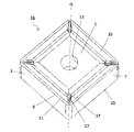
- inserts 1a to 1c of the present disclosure will be described with reference to FIGS. 6 to 11.
- the differences between the inserts 1a to 1c and the insert 1 will be mainly described, and detailed description of the points having the same configuration as the insert 1 may be omitted.
- the inserts 1a to 1c may have a breaker groove 35 located on the first surface 5 along the cutting edge 11, as in the case of the non-limiting example shown in FIGS. 6 to 11.
- the breaker groove 35 may approach the reference surface S as the distance from the cutting edge 11 increases.
- the inserts 1a to 1c may have a convex portion 37 located inside the first surface 5 with respect to the cutting edge 11.
- the convex portion 37 can control the flow direction of chips generated by the cutting edge 11. Further, the convex portion 37 can exert a chip dividing effect.
- the convex portion 37 is also called a breaker protrusion. At least a part of the convex portion 37 may be located inside the first surface 5 with respect to the breaker groove 35.
- the convex portion 37 may extend along the bisector of the corner portion 33.
- the groove 17 may be positioned so as to overlap the convex portion 37.
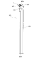
- the cutting tool 101 has a length extending from the first end 105a (upper end in FIG. 12) to the second end 105b (lower end in FIG. 12), as in the non-limiting example shown in FIG. It may have a holder 105 having a pocket 103 located on the side and the above-mentioned insert 1 located in the pocket 103.
- the cutting tool 101 has the insert 1, it can be cut at a high speed because of its excellent cooling performance, and stable cutting can be performed for a long period of time.
- the description of the groove 17 and the like is omitted.
- the case where the shape when the first surface 5 is viewed in a plan view is a rhombus shape is illustrated. These points are the same in FIG. 13, which will be described later.
- the holder 105 may be a rod-shaped body extending from the first end 105a toward the second end 105b.
- the first end 105a is called the "tip" and the second end 105b is called the "rear end”.
- the length from the first end 105a to the second end 105b is not limited to a specific value.
- the length from the first end 105a to the second end 105b may be set to about 100 to 250 mm.
- the pocket 103 is a portion to which the insert 1 is mounted, and may have a seating surface parallel to the lower surface of the holder 105 and a restraint side surface perpendicular to or inclined with respect to the seating surface. Further, the pocket 103 may be opened on the side of the first end 105a of the holder 105.
- the insert 1 may be located in the pocket 103.
- the lower surface of the insert 1 may be in direct contact with the pocket 103, or a sheet (not shown) may be sandwiched between the insert 1 and the pocket 103.
- the insert 1 is provided so that at least a part of the portion used as the cutting edge 11 on the ridge line 9 where the first surface 5 which is the rake surface 5 and the second surface 7 which is the flank surface 7 intersects protrudes outward from the holder 105. It may be attached to the holder 105.
- the insert 1 may be attached to the holder 105 by a fixing screw 107. That is, the fixing screw 107 is inserted into the through hole 13 of the insert 1, the tip of the fixing screw 107 is inserted into the screw hole (not shown) formed in the pocket 103, and the screw portions are screwed together to insert the insert. 1 may be mounted on the holder 105.
- the cutting tool 101 may be provided with a hose (not shown) having a nozzle at the tip in order to supply the cooling liquid to the cutting edge 11.
- a pump for supplying the coolant may be connected to this hose.
- the cutting tool 101 may be provided with the nozzle 109 for supplying the cooling liquid to the cutting edge 11 in the holder 105.
- the ejection port of the nozzle 109 When the ejection port of the nozzle 109 is located in the vicinity of the insert 1, it becomes easy to supply the coolant to the cutting edge 11.
- the nozzle 109 may be fixed to a part of the holder 105.
- a hole may be provided in the holder 105 and used as the nozzle 109.
- the coolant discharged from the nozzle 109 may be, for example, a water-soluble one or an oil-based one.
- the nozzle 109 may be connected to a pump (not shown), and may, for example, discharge the coolant at a pressure of 0.5 to 20 MPa. When the pressure is 10 MPa or more, processing at higher speed becomes possible.
- the holder 105 may have a flow path through which the coolant flows.
- steel, cast iron, or the like can be used as the material of the holder 105.
- steel having high toughness may be used.
- a cutting tool 101 used for so-called turning is illustrated.
- the turning process include inner diameter processing, outer diameter processing, and grooving processing.
- the cutting tool is not limited to the one used for turning.
- the above-mentioned insert 1 may be used as a cutting tool used for milling.
- the cutting tool 101 has an insert 1, but is not limited to such a form.
- the cutting tool 101 may have any of the inserts 1a to 1c.
Landscapes
- Engineering & Computer Science (AREA)
- Mechanical Engineering (AREA)
- Cutting Tools, Boring Holders, And Turrets (AREA)
Priority Applications (2)
| Application Number | Priority Date | Filing Date | Title |
|---|---|---|---|
| US18/251,397 US20240116113A1 (en) | 2020-11-09 | 2021-10-28 | Insert and cutting tool |
| JP2022560742A JP7598943B2 (ja) | 2020-11-09 | 2021-10-28 | インサートおよび切削工具 |
Applications Claiming Priority (2)
| Application Number | Priority Date | Filing Date | Title |
|---|---|---|---|
| JP2020186482 | 2020-11-09 | ||
| JP2020-186482 | 2020-11-09 |
Publications (1)
| Publication Number | Publication Date |
|---|---|
| WO2022097564A1 true WO2022097564A1 (ja) | 2022-05-12 |
Family
ID=81457881
Family Applications (1)
| Application Number | Title | Priority Date | Filing Date |
|---|---|---|---|
| PCT/JP2021/039811 Ceased WO2022097564A1 (ja) | 2020-11-09 | 2021-10-28 | インサートおよび切削工具 |
Country Status (3)
| Country | Link |
|---|---|
| US (1) | US20240116113A1 (https=) |
| JP (1) | JP7598943B2 (https=) |
| WO (1) | WO2022097564A1 (https=) |
Families Citing this family (2)
| Publication number | Priority date | Publication date | Assignee | Title |
|---|---|---|---|---|
| EP3851231A1 (en) * | 2020-01-17 | 2021-07-21 | Seco Tools Ab | A cutting insert |
| EP3919211A1 (en) * | 2020-06-02 | 2021-12-08 | Ceratizit Luxembourg Sàrl | Milling tool, use thereof and milling process |
Citations (5)
| Publication number | Priority date | Publication date | Assignee | Title |
|---|---|---|---|---|
| DE4134335A1 (de) * | 1991-10-17 | 1993-04-22 | Neumo Grundbesitz Gmbh | Zerspanungs-schneidwerkzeug |
| JP2014018891A (ja) * | 2012-07-13 | 2014-02-03 | Mitsubishi Materials Corp | 切削インサート |
| JP2016132054A (ja) * | 2015-01-19 | 2016-07-25 | 株式会社豊田中央研究所 | 切削工具および切削方法 |
| WO2020184667A1 (ja) * | 2019-03-14 | 2020-09-17 | 京セラ株式会社 | インサートおよび切削工具 |
| JP2020529326A (ja) * | 2017-08-02 | 2020-10-08 | イスカル リミテッド | 切屑形成配置構成を有する仕上げ旋削用ネガティブインサート |
Family Cites Families (7)
| Publication number | Priority date | Publication date | Assignee | Title |
|---|---|---|---|---|
| US4259033A (en) * | 1974-11-29 | 1981-03-31 | Kennametal Inc. | Cutting insert |
| US4340324A (en) * | 1980-08-28 | 1982-07-20 | Kennametal Inc. | Cutting insert |
| IL97746A (en) * | 1991-04-02 | 1995-01-24 | Iscar Ltd | Metal cutting tool |
| US5203649A (en) * | 1991-10-07 | 1993-04-20 | Gte Valentine Corporation | High productivity, high metal removal rate insert |
| US8596935B2 (en) * | 2010-10-08 | 2013-12-03 | TDY Industries, LLC | Cutting tools and cutting inserts including internal cooling |
| KR101394631B1 (ko) * | 2012-06-14 | 2014-05-13 | 한국야금 주식회사 | 절삭 인서트 |
| JP6356781B2 (ja) * | 2014-02-26 | 2018-07-11 | 京セラ株式会社 | 切削インサート、切削工具及び切削加工物の製造方法 |
-
2021
- 2021-10-28 US US18/251,397 patent/US20240116113A1/en active Pending
- 2021-10-28 JP JP2022560742A patent/JP7598943B2/ja active Active
- 2021-10-28 WO PCT/JP2021/039811 patent/WO2022097564A1/ja not_active Ceased
Patent Citations (5)
| Publication number | Priority date | Publication date | Assignee | Title |
|---|---|---|---|---|
| DE4134335A1 (de) * | 1991-10-17 | 1993-04-22 | Neumo Grundbesitz Gmbh | Zerspanungs-schneidwerkzeug |
| JP2014018891A (ja) * | 2012-07-13 | 2014-02-03 | Mitsubishi Materials Corp | 切削インサート |
| JP2016132054A (ja) * | 2015-01-19 | 2016-07-25 | 株式会社豊田中央研究所 | 切削工具および切削方法 |
| JP2020529326A (ja) * | 2017-08-02 | 2020-10-08 | イスカル リミテッド | 切屑形成配置構成を有する仕上げ旋削用ネガティブインサート |
| WO2020184667A1 (ja) * | 2019-03-14 | 2020-09-17 | 京セラ株式会社 | インサートおよび切削工具 |
Also Published As
| Publication number | Publication date |
|---|---|
| US20240116113A1 (en) | 2024-04-11 |
| JP7598943B2 (ja) | 2024-12-12 |
| JPWO2022097564A1 (https=) | 2022-05-12 |
Similar Documents
| Publication | Publication Date | Title |
|---|---|---|
| EP1904253B1 (en) | A cutting insert for turning with chip-breaker arrangement providing room for a cooling jet | |
| KR102349807B1 (ko) | 일체형으로 형성된 나사형 생크-커넥터를 갖는 교체 가능한 정면-밀링 헤드 | |
| EP3771512B1 (en) | Drill | |
| WO2015037617A1 (ja) | 刃先交換式回転切削工具及びそれに用いるインサート | |
| JP6621044B1 (ja) | 切削インサートおよびフライス工具 | |
| SE535282C2 (sv) | Skär med radieparti, verktyg och anordning för fräsning | |
| JP7598943B2 (ja) | インサートおよび切削工具 | |
| JP4816496B2 (ja) | 穴加工工具 | |
| US20210114118A1 (en) | Insert and cutting tool assembly comprising same | |
| JP7238094B2 (ja) | インサートおよび切削工具 | |
| JP7295219B2 (ja) | インサートおよび切削工具 | |
| WO2017217481A1 (ja) | 切削インサート、切削工具及び切削加工物の製造方法 | |
| JP6974230B2 (ja) | 切削インサート、切削工具及び切削加工物の製造方法 | |
| JP7598945B2 (ja) | インサートおよび切削工具 | |
| JP2022081568A (ja) | 切削インサートおよび刃先交換式ボールエンドミル | |
| JP7598944B2 (ja) | インサートおよび切削工具 | |
| JP2022130806A (ja) | 切削インサート | |
| JP2022155847A (ja) | ボーリングバー | |
| JP2019155558A (ja) | 切削工具 | |
| JP2025038538A (ja) | 切削工具 | |
| US20250269437A1 (en) | Cutting tool | |
| JP2024015617A (ja) | 切削工具 | |
| WO2026034060A1 (ja) | 切削インサート、切削工具及び切削加工物の製造方法 |
Legal Events
| Date | Code | Title | Description |
|---|---|---|---|
| 121 | Ep: the epo has been informed by wipo that ep was designated in this application |
Ref document number: 21889117 Country of ref document: EP Kind code of ref document: A1 |
|
| ENP | Entry into the national phase |
Ref document number: 2022560742 Country of ref document: JP Kind code of ref document: A |
|
| NENP | Non-entry into the national phase |
Ref country code: DE |
|
| 122 | Ep: pct application non-entry in european phase |
Ref document number: 21889117 Country of ref document: EP Kind code of ref document: A1 |