WO2022097402A1 - 電子ペン - Google Patents
電子ペン Download PDFInfo
- Publication number
- WO2022097402A1 WO2022097402A1 PCT/JP2021/036591 JP2021036591W WO2022097402A1 WO 2022097402 A1 WO2022097402 A1 WO 2022097402A1 JP 2021036591 W JP2021036591 W JP 2021036591W WO 2022097402 A1 WO2022097402 A1 WO 2022097402A1
- Authority
- WO
- WIPO (PCT)
- Prior art keywords
- electronic pen
- main body
- sealing member
- holder
- elastic body
- Prior art date
- Legal status (The legal status is an assumption and is not a legal conclusion. Google has not performed a legal analysis and makes no representation as to the accuracy of the status listed.)
- Ceased
Links
Images


Classifications
-
- G—PHYSICS
- G06—COMPUTING OR CALCULATING; COUNTING
- G06F—ELECTRIC DIGITAL DATA PROCESSING
- G06F3/00—Input arrangements for transferring data to be processed into a form capable of being handled by the computer; Output arrangements for transferring data from processing unit to output unit, e.g. interface arrangements
- G06F3/01—Input arrangements or combined input and output arrangements for interaction between user and computer
- G06F3/03—Arrangements for converting the position or the displacement of a member into a coded form
- G06F3/033—Pointing devices displaced or positioned by the user, e.g. mice, trackballs, pens or joysticks; Accessories therefor
- G06F3/0354—Pointing devices displaced or positioned by the user, e.g. mice, trackballs, pens or joysticks; Accessories therefor with detection of two-dimensional [2D] relative movements between the device, or an operating part thereof, and a plane or surface, e.g. 2D mice, trackballs, pens or pucks
- G06F3/03545—Pens or stylus
-
- G—PHYSICS
- G06—COMPUTING OR CALCULATING; COUNTING
- G06F—ELECTRIC DIGITAL DATA PROCESSING
- G06F3/00—Input arrangements for transferring data to be processed into a form capable of being handled by the computer; Output arrangements for transferring data from processing unit to output unit, e.g. interface arrangements
- G06F3/01—Input arrangements or combined input and output arrangements for interaction between user and computer
- G06F3/03—Arrangements for converting the position or the displacement of a member into a coded form
- G06F3/033—Pointing devices displaced or positioned by the user, e.g. mice, trackballs, pens or joysticks; Accessories therefor
- G06F3/038—Control and interface arrangements therefor, e.g. drivers or device-embedded control circuitry
- G06F3/0383—Signal control means within the pointing device
Definitions
- the present invention relates to an electronic pen that enables input of information by instructing coordinates to a position detecting device mounted on an electronic device such as a tablet PC (Personal Computer), for example.
- a position detecting device mounted on an electronic device such as a tablet PC (Personal Computer), for example.
- Patent Document 1 discloses a technique for performing overall sealing by shielding the entire important component of an electronic pen such as a coil and a circuit board.
- Patent Document 2 discloses a technique of filling a hollow portion in an internal housing containing a component for realizing an electronic pen function with a resin to add a waterproof function.
- Patent Document 3 discloses a technique of providing a waterproof elastic member (cap member or sealing member) on the pen tip side inside the housing or on the circuit board connection portion to prevent water or the like from entering from the outside. ing.
- Patent Documents 1 to 3 described above are useful as techniques for adding a waterproof function to an electronic pen.
- electronic pens not only to have a waterproof function but also to be more suitable for use in foldable mobile terminals called foldable terminals and the like. Since the fal double terminal is a foldable type, it is not possible to provide a hard protective layer such as tempered glass on the display screen as in a conventional mobile terminal.
- An electronic pen main body including a first sealing member that covers the periphery of the tip side and a second sealing member provided along the outer edge at a position away from the tip to the rear end side.
- An electronic pen that is a tubular body and has an inner body in which the first sealing member and the second sealing member are in close contact with the inner wall surface by inserting the tip end side of the electronic pen main body. I will provide a.
- the first sealing member and the second sealing member of the main body of the electronic pen are sealed by being in close contact with the sealing member and the inner body, and a waterproof function is imparted to the portion. Will be done.
- the electronic pen body and the inner body are integrated and can be moved together. This makes it possible to easily and sufficiently take measures for foldable terminals.
- an electromagnetic induction type electronic pen is provided with a resonance circuit configured by connecting a coil and a capacitor, and sends and receives a magnetic field to and from a position detection device to indicate a position and notify a pen pressure. ..
- a coil is provided on the pen tip side, but if this coil part gets wet with water or the like, the electrical characteristics will change, so the coil part will change. Will need to be waterproofed.
- a coil for charging the battery may be mounted, and it will be necessary to take waterproof measures for the coil part.
- waterproof measures there are various types of electronic pens, and there is an increasing need to take waterproof measures for each of them.
- the present invention is applicable to various electronic pens in which waterproof measures should be taken. In the following, for the sake of simplicity, the case where the present invention is applied to an electromagnetic induction type electronic pen will be described as an example.
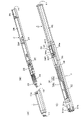
- FIG. 1 is a perspective view for explaining the internal configuration of the electronic pen of the embodiment.
- the electronic pen of this embodiment is composed of four major parts: an inner body 1, an electronic pen main body 2, a main body holder 3, and an elastic body holder 4.
- the inner body 1 is a tubular body having a tapered tip side, a hollow inside, a tip opening 11 provided at the tip, and a rear portion. A rear end opening 12 is provided at the end.
- the upper surface and the lower surface of the inner body 1 are formed in a plane shape, and a fitting protrusion 13a is provided on the rear end side of the upper surface.
- a fitting protrusion 13b is also provided on the rear end side of the lower surface at a position facing the fitting protrusion 13a.
- the electronic pen main body 2 is a part that realizes the electronic pen function. As shown in FIG. 1B, the appearance of the electronic pen main body 2 includes a core 21, a first sealing member 22, a coil 24, a pen pressure detecting portion 25, a second sealing member 26, a substrate holding portion 27, and a circuit. It is composed of a substrate 28 and a battery 29.
- the core body 21 has a rod shape, and is composed of a pen tip portion having a rounded tip and a shaft portion extending from the pen tip portion to the rear end side.
- the first sealing member 22 has a cup shape having a thickness formed of, for example, an elastic material such as synthetic rubber, and has an opening at the rear end surface and an opening at the front end surface as well as a core body. 21 can be inserted and removed.
- the first sealing member 22 is attached to the tip end side of the electronic pen main body portion 2 and is in close contact with the electronic pen main body portion 2 so as to cover the periphery of the tip end side.
- the coil 24 is formed by winding an insulating conductor around the side surface of the ferrite core 23, which is not visible in FIG. Both ends of the insulating lead wire constituting the coil 24 are stretched toward the rear end side and connected to a capacitor provided on the circuit board 28 described later to form a resonance circuit between the coil 24 and the capacitor.
- the pen pressure detecting unit 25 is configured to include a variable capacitance capacitor whose capacitance changes according to the pressing of the core body 21.
- This variable capacitance capacitor is connected in parallel to the resonant circuit formed by the coil 24 and the capacitor.
- information indicating the writing pressure applied to the core body 21 can be included in the magnetic field (signal) transmitted from the resonance circuit and transmitted.
- the second sealing member 26 is formed of a ring-shaped linear body having a certain thickness by, for example, an elastic material such as synthetic rubber, and has a tubular shape located at the rear stage of the pen pressure detection unit 25. It is provided in close contact with the outer edge of the formed substrate holding portion 27.
- the substrate holding portion 27 is provided in the rear stage of the second sealing member 26 so as to be connected to the pen pressure detecting portion 25, and the upper surface side is an opening except for the connecting portion with the pen pressure detecting unit 25. It has a shape.
- the board holding portion 27 includes a board area and a battery area. As shown in FIG. 1 (B), a circuit board 28 is mounted in the board area of the board holding portion 27, and a battery 29 is provided in the battery area. It will be installed.
- the circuit board 28 has an electronic circuit formed by various circuit components such as a capacitor for a resonance circuit connected in parallel to the coil 24, a control IC (Integrated Circuit), and a push switch (button switch) SW. It is a thing.
- the push switch SW is for realizing a so-called side switch provided on the side surface of the electronic pen and operated by the user. That is, different magnetic fields (signals) can be transmitted when the press switch SW is pressed and when it is not pressed.
- the electronic pen main body 2 is inserted from the pen tip side through the rear end opening 12, and is attached to the tip side of the electronic pen main body 2.
- the outer shape of the first sealing member 22 has the same shape as the corresponding inner portion of the inner body 1, but the size of the first sealing member 22 is the corresponding inner portion of the inner body 1. It is a little bigger than.
- the outer shape of the second sealing member 26 has the same shape as the corresponding inner portion of the inner body 1, but the size of the second sealing member 26 is larger for the second sealing member 26 than for the corresponding inner portion of the inner body 1. It's getting a little bigger.
- both the first sealing member 22 and the second sealing member 26 are made of an elastic material. Therefore, when the electronic pen main body 2 is inserted from the pen tip side through the rear end opening 12 of the inner body 1 and pushed to a fixed position, each of the first sealing member 22 and the second sealing member 26 becomes an inner body. It is in close contact with the inner wall at the corresponding position of 1. As a result, the space between the first sealing member 22 and the second sealing member 26 of the electronic pen main body 2 is sealed by the inner body 1 coming into close contact with the first sealing member 22 and the second sealing member 26. , Water, etc. can be prevented from entering. That is, a waterproof function can be added to the portion of the electronic pen main body 2 covered by the inner body 1.
- the circuit board 28 is covered with a resin to add a waterproof function to the circuit board 28 as well.
- a resin to add a waterproof function to the circuit board 28 as well.
- a liquid plastic UV bond
- a waterproof function is added to the entire circuit board area of the board holding portion 27. In this case, the thickness of the liquid plastic is reduced in the portion so that the push switch SW can be operated.
- the main body holder 3 holds the electronic pen main body 2, and includes connection plates 31a and 31b, a circuit board holding portion 32, a battery holding portion 33, a support portion 34, a pusher portion 35, and connecting arms 36a and 36b. Be prepared.
- the electronic pen main body 2 to which the inner body 1 is attached is inserted into the main body holder 3 from the connection plates 31a and 31b side, and the rear end surface 2T of the electronic pen main body 2 is the battery holding portion 33. It is made to come into contact with the bottom surface 33T.
- the connection plates 31a and 31b hold the electronic pen main body 2 by sandwiching the rear ends of the inner body 1 from above and below.
- connection plate 31a is provided with a fitting hole 31ah, and the connection plate 31b faces the fitting hole 31ah of the connection plate 31a, although not shown.
- a fitting hole 31bh is provided at the position. Therefore, the fitting protrusion 13a on the upper surface of the inner body 1 is fitted in the fitting hole 31ah of the connection plate 31a, and the fitting protrusion 13b on the lower surface of the inner body 1 is fitted in the fitting hole 31bh of the connection plate 31b. Fits. As a result, the electronic pen main body 2 to which the inner body 1 is attached does not easily come off from the main body holder 3.
- the portion between the circuit board holding portion 32 and the battery holding portion 33 has a half-pipe shape with an opening on the upper surface side.
- the support portion 34 is a portion formed in an arch shape at the boundary portion between the circuit board holding portion 32 and the battery holding portion 33. Therefore, the battery area of the substrate holding portion 27 of the electronic pen main body 2 passes under the support portion 34 and reaches the battery holding portion 33 on the rear side of the support portion 34. In this case, the board area of the board holding part 27 of the electronic pen main body 2 is located in the circuit board holding part 32 on the front side of the support part 34.
- the pusher portion 35 is a hollow portion extended from the support portion 34 toward the pen tip side, and passes directly above the push switch SW of the circuit board 28 of the electronic pen main body portion 2. As shown in FIG. 1C, the pusher portion 35 has an elongated plate shape including a shaft portion 35a and a pressing portion 35b. As described above, since the upper surface of the substrate holding portion 27 of the electronic pen main body 2 and the upper surface of the circuit board holding portion 32 of the main body holder 3 are both open, the pressing portion 35b of the pusher portion 35b. The pressing switch SW of the circuit board 28 can be pressed via the above.
- the pusher portion 35 acts as a leaf spring with the support portion 34 as a fulcrum. Therefore, when the upper surface of the pressing portion 35b of the pusher portion 35 is pressed, the pressing portion 35b is lowered to press the pressing switch SW of the circuit board 28. When the pressing on the upper surface of the pressing portion 35b is released, the pusher portion 35 acts as a leaf spring, the pressing portion 35b returns to the original position, and the pressing of the pressing switch SW is released. As described above, the pusher portion 35 is a member for constituting the side switch.
- the connecting arms 36a and 36b are portions that enable connection with the elastic body holder 4, and the holding portion 41 of the elastic body holder 4 described later is sandwiched from the left and right so that the main body holder 3 is attached to the elastic body holder 4. Connecting. Therefore, the electronic pen main body 2 to which the inner body 1 is mounted is held by the main body holder 3, and the main body holder 3 is connected to the elastic body holder 4.
- the elastic body holder 4 includes a holding portion 41 and a stretching portion 42. As shown in FIG. 1C, the holding portion 41 holds the coil spring 43 as an elastic body.
- the stretched portion 42 is a portion stretched from the rear end surface of the holding portion 41 to the rear end side, and is an internal structure of the electronic pen of this embodiment (inner body 1, electronic pen main body 2, main body holder 3, The purpose is to make the portion made of the elastic body holder 4) a predetermined length. Grooves are provided on the left and right side surfaces of the holding portion 41, and the connecting arms 36a and 36b of the main body holder 3 described above are fitted into these left and right grooves to fit the elastic holder 4 with respect to the elastic holder 4.
- the main body holder 3 is connected.
- the rear ends of the connecting arms 36a and 36b are provided with convex portions so as to project inward, and engage with the front ends of the left and right side groove portions of the holding portion 41.
- the main body holder 3 is prevented from being easily disengaged from the elastic body holder 4, and the main body holder 3 is pushed in and out of the elastic body holder 4 in the axial direction. That is, it is possible to slide and move (slide movement).
- a predetermined writing pressure for example, 300 g (grams) or more, is applied to the core body 21 of the electronic pen main body 2 mounted on the main body holder 3. It is assumed that pen pressure is applied. In this case, the main body holder 3 is pushed toward the elastic body holder 4, the coil spring 43 contracts, and the distance between the outer bottom surface 36T of the main body holder 3 and the inner bottom surface 41T of the holding portion 41 of the elastic body holder 4. Shrinks.
- the coil spring 43 is extended and the distance between the outer bottom surface 36T of the main body holder 3 and the inner bottom surface 41T of the holding portion 41 of the elastic body holder 4 is restored to the original distance.
- the coil spring 43 is interposed between the main body holder 3 and the elastic body holder 4, so that the main body holder 3 accommodating the electronic pen main body 2 can be accommodated according to the writing pressure applied to the core 21. Achieves the action of pushing in and back in the axial direction.
- the coil spring 43 does not contract.
- the predetermined writing pressure 300 g or more
- the coil spring 43 contracts, causing an action of retracting the core body 21 in the axial direction.
- FIG. 2 is a perspective view for explaining the electronic pen of the embodiment.
- FIG. 2A shows the internal structure of the electronic pen in a state where each part of the inner body 1, the electronic pen main body 2, the main body holder 3, and the elastic body holder 4 described with reference to FIG. 1 is connected. There is. That is, FIG. 2A shows a state in which the electronic pen main body 2 to which the inner body 1 is attached is attached to the main body holder 3, and the main body holder 3 is further connected to the elastic body holder 4. .
- FIG. 2B shows an electronic pen in a mode in which the internal structure of the electronic pen shown in FIG. 2A is housed in the outer housing 5 and is used by a user (end user). Shows the appearance.
- the outer housing 5 is a tubular body having a tapered pen tip side, and is provided with a tip opening at the tip of the pen tip and a rear end opening at the rear end side.
- the internal structure of the electronic pen shown in FIG. 2A is inserted from the rear end opening of the outer housing 5, so that the core 21 protrudes from the front end opening. In this state, the tip portion of the inner body 1 is in contact with the inner tip portion of the outer housing 5.
- a columnar rear end cap 7 is fitted into the rear end opening of the outer housing 5.
- the rear end cap 7 includes a fitting portion fitted inside the outer housing 5 and an exposed portion exposed to the outside.
- the outer diameter of the fitting portion of the rear end cap is slightly longer than the inner diameter of the outer housing 5, and the entire fitting portion is pushed into the outer housing 5 so as not to be easily disengaged.
- the outer diameter of the exposed portion of the rear end cap 7 is substantially the same as the outer diameter of the outer housing 5.
- the internal structure shown in FIG. 2A is attached to the outer housing 5 and used as an electronic pen.
- the coil spring sandwiched between the main body holder 3 and the elastic body holder 4 contracts, and the main body
- the core body 21 is housed in the outer housing by sliding the portion holder 3 toward the rear end side.
- the core body 21 is prevented from applying a writing pressure exceeding a predetermined value to the operation surface.
- the coil spring 43 expands and the core body 21 returns to the state of protruding from the tip opening of the outer housing 5.
- a side opening 5h is provided on the side surface of the outer housing 5.
- the side opening 5h is provided at a position corresponding to the pressing switch SW provided on the circuit board 28 of the electronic pen main body 2, and this position corresponds to the position of the pressing portion 35b of the pusher portion 35.
- the operation unit 6 is fitted into the side surface opening 5h.
- FIG. 3 is a diagram for explaining the configuration of the pen tip side of the electronic pen according to the embodiment, and is cut in the longitudinal direction of the electronic pen so as to be divided into a back side and a front side with the operation unit 6 on the upper side. However, it is a cross-sectional view when the front side is removed.
- the pen tip portion of the core body 21 of the electronic pen main body portion 2 is shown in FIG. (B), as shown in FIG. 3, the tip opening of the outer housing 5 is in a protruding state.
- the shaft portion of the core body 21 penetrates the through hole of the ferrite core 23, which is a cylindrical body, and reaches the pen pressure detecting portion 25.
- a coil 24 is formed on the side surface of the ferrite core 23 by winding an insulating conductor, and a first sealing member 22 is provided on the front end side of the coil 24 so as to cover the front end side of the ferrite core 23. Has been done.
- the pen pressure detecting unit 25 includes a pressing member 251, a first electrode 252, a dielectric 253, and a second electrode 254.
- the rear end side of the shaft portion of the core body 21 is inserted into the pressing member 251.
- a gap is provided between the first electrode 252 and one surface of the dielectric 253 facing the first electrode 252, via the pressing member 251 according to the writing pressure applied to the pen tip portion of the core body 21.
- the first electrode 252 approaches and moves away from the dielectric 253. Since the second electrode is provided on the other surface of the dielectric 253, it is based on the capacitance between the first electrode 252 and the second electrode 254 that changes according to the writing pressure. Pen pressure can be detected.
- a connecting member 2CN is provided at the rear stage of the second electrode 254.
- the connecting member 2CN connects the pen pressure detecting unit 25 and the substrate holding unit 27. That is, as shown in FIG. 3, the pen pressure detecting unit 25 is connected to the front stage of the connecting member 2CN, and the pen tip side tip portion of the substrate holding unit 27 is fitted to the rear stage of the connecting member 2CN.
- the pen pressure detecting unit 25 and the substrate holding unit 27 are connected via the connecting member 2CN.
- the pen tip side of the substrate holding portion 27 is formed in a cylindrical shape, and a ring-shaped second sealing member is provided around the side surface thereof in close contact with the periphery (outer edge) of the side surface. Further, as described above, the inner body 1 is attached to the pen tip side of the electronic pen main body 2.
- the pen tip side inside the inner body 1 is in close contact with the first sealing member, and the second sealing inside the inner body 1 is in close contact with the second sealing member. Adhere to the member.
- the portion of the inner body 1 consisting of the coil 24 and the pen pressure detecting portion 25 is sealed by the first sealing member 22 and the second sealing member 26 in close contact with the inner body 1 to be waterproof. The function is realized.
- the circuit board 28 and the battery 29 are mounted on the board holding portion 27.
- the upper surface side of the circuit board 28 is filled with a UV bond, and by irradiating with ultraviolet rays, the circuit board 28 is cured in close contact with the inner wall of the circuit board 28 and the substrate holding portion 27 to form a protective layer 28B, as described above.
- the waterproof function is realized for 28 parts of the circuit board.
- the circuit board 28 is a double-sided board in which circuit components are arranged on both sides. However, by filling the inside of the board holding portion 27 with a UV bond, water or the like can also be formed on the lower surface side of the circuit board 28. You can prevent the liquid from entering.
- a push switch SW is provided on the upper surface of the circuit board 28, but the thickness of the push switch SW portion is reduced so that the push operation can be performed and the protective layer 28B by the UB bond is thinned. ing.
- the main body holder 3 at least the upper surface side of the portion of the electronic pen main body 2 where the circuit board 28 is located is an opening, and the portion is in the shape of a half pipe. Further, as shown in FIG. 3, the main body holder 3 includes a pusher portion 35, which is an elongated plate-like body having a hollow extending from the support portion 34 toward the pen tip side.
- the pusher portion 35 includes a shaft portion 35a and a pressing portion 35b, and the pressing portion 35b is in a position where the pressing switch SW provided on the circuit board 28 can be pressed.
- the pressing portion 35b has a convex portion on the lower side, and the pressing portion 35 is pressed by pressing the operating portion 6 provided in the side opening portion 5h of the outer housing 5.
- the pressing switch SW can be pressed via the portion 35b.
- the pusher unit 35 acts as a leaf spring. Therefore, when the pressing applied to the operating portion 6 is released, the pusher portion 35 acts so as to return to the original state with the supporting portion 34 as a fulcrum. As a result, the pressing of the pressing switch SW is released, and the operation unit 6 is also pushed up to return to the original state.
- a side switch capable of reliably switching between a pressed / non-pressed state is realized with a simple configuration.
- the operation unit 6 is provided with a front end overhanging portion slightly overhanging toward the pen tip at the front end, and a rear end overhanging portion slightly overhanging toward the rear end at the rear end. Therefore, the operation unit 6 is prevented from easily coming off from the side opening of the outer housing 5. That is, in the operation unit 6, the front end overhanging portion and the rear end overhanging portion are merely engaged with the inner wall of the outer housing 5, and are merely mounted on the upper surface of the pressing portion 35b of the pusher portion 35.
- the operation unit 6 does not interfere with the sliding movement of the main body holder 3.
- the operation unit 6 can be attached by pushing it in.
- the operation unit 6 can be easily removed from the inside of the outer housing 5 by removing the internal structure shown in FIG. 2 (A) from the outer housing 5. It is possible to remove it.
- FIG. 4 is a diagram for explaining a state before and after an excessive writing pressure is applied to the electronic pen of the embodiment, with the side on which the operation unit 6 is located as the upper side. It is sectional drawing in the case of cutting up and down in the longitudinal direction with the opposite side as the lower side, and removing the upper side.
- FIG. 4 (B) shows the state of the core body 21. It shows a state in which a writing pressure of 300 g or more is applied to the pen tip.
- the core body 21 is as shown in FIG. 4 (A).
- the state in which the pen tip portion of 21 protrudes from the tip opening of the outer housing 5 is maintained. Therefore, when the electronic pen of this embodiment is used on the operation surface of the foldable terminal, it can function normally as an electronic pen if the writing pressure is less than 300 g.
- the coil spring 43 begins to contract, and the main body holder 3 to which the electronic pen main body 2 is attached gradually moves to the rear end side.
- the pen tip portion of the core body 21 enters the inside of the outer housing 5.
- a writing pressure of 300 g or more is not applied to the operation surface.
- the pen tip of the core 21 is housed in the outer housing 5 as shown in FIG. 4 (B), and the outer casing is provided. It will not protrude from the tip opening of the body 5.
- the pen tip portion of the core body 21 prevents the writing pressure of 300 g or more from being applied to a very narrow range of the operation surface. Therefore, the operation surface of the foldable terminal, which cannot be provided with a strong protective layer such as tempered glass, is not damaged by excessive writing pressure applied through the pen tip portion of the core body 21. can.
- the coil spring 43 expands and can return to the state shown in FIG. 4 (A).
- an internal structure including an inner body 1, an electronic pen main body 2, a main body holder 3, and an elastic body holder 4 is provided.
- the body can be slid and moved to the rear end side by a distance ⁇ minutes in the outer housing 5.
- the main body holder 3 to which the electronic pen main body 2 is mounted slides and moves according to the writing pressure applied to the pen tip of the core 21, the inside mounted on the electronic pen main body 2 No physical change occurs in the body 1 portion or the protective layer 28B portion on the circuit board 28. Therefore, even if the internal structure slides and moves, the waterproof function of the inner body 1 portion and the waterproof function of the protective layer 28B provided on the circuit board 28 are not deteriorated or lost.
- the coil 24 and the pen pressure detecting unit 25 can be provided with a waterproof function by the inner body 1, the first sealing member 22, and the second sealing member 26. Further, the waterproof function can be realized by providing the protective layer 28B by UV bond on the circuit board 28 portion. These waterproof functions are not affected even if the main body holder 3 to which the electronic pen main body 2 is mounted slides and moves according to the writing pressure applied to the pen tip of the core 21, and is said to be the same. The waterproof function of the part will not be deteriorated or lost. Therefore, it is possible to add a waterproof function and realize a suitable electronic pen for use in a foldable terminal.
- the elastic body holder 4 is provided with the stretched portion 42, but the present invention is not limited to this.
- the function of the stretched portion 42 is to increase the length of the fitting portion of the rear end cap 7, or to hold the outer housing 5 from the front stage portion for accommodating the internal structure and the internal accommodating body from the rear end side. It is also possible to have a configuration that is divided into two parts, that is, the rear part.
- the coil spring 43 is used as the elastic body located between the main body holder 3 and the elastic body holder 4, but the present invention is not limited to this.
- various elastic bodies capable of functioning similarly to the coil spring 43 such as synthetic rubber or sponge can be used.
- the front and rear overhanging portions engage with the front and rear inner walls of the side opening 5h of the outer housing 5 from the outer housing 5. I tried not to come off, but it is not limited to this.
- an engaging portion protruding portion having a portion protruding with respect to the direction in which the lower side intersects the axial direction is provided corresponding to the slit of the pressing portion 35b.
Landscapes
- Engineering & Computer Science (AREA)
- General Engineering & Computer Science (AREA)
- Theoretical Computer Science (AREA)
- Human Computer Interaction (AREA)
- Physics & Mathematics (AREA)
- General Physics & Mathematics (AREA)
- Position Input By Displaying (AREA)
- Casings For Electric Apparatus (AREA)
- Telephone Set Structure (AREA)
- Mechanical Pencils And Projecting And Retracting Systems Therefor, And Multi-System Writing Instruments (AREA)
Priority Applications (5)
| Application Number | Priority Date | Filing Date | Title |
|---|---|---|---|
| JP2022560680A JP7713467B2 (ja) | 2020-11-06 | 2021-10-04 | 電子ペン |
| CN202180056041.0A CN116134406A (zh) | 2020-11-06 | 2021-10-04 | 电子笔 |
| KR1020237004610A KR20230095912A (ko) | 2020-11-06 | 2021-10-04 | 전자 펜 |
| US18/193,451 US11941188B2 (en) | 2020-11-06 | 2023-03-30 | Electronic pen |
| JP2025118471A JP2025133966A (ja) | 2020-11-06 | 2025-07-14 | 電子ペン |
Applications Claiming Priority (2)
| Application Number | Priority Date | Filing Date | Title |
|---|---|---|---|
| JP2020-185698 | 2020-11-06 | ||
| JP2020185698 | 2020-11-06 |
Related Child Applications (1)
| Application Number | Title | Priority Date | Filing Date |
|---|---|---|---|
| US18/193,451 Continuation US11941188B2 (en) | 2020-11-06 | 2023-03-30 | Electronic pen |
Publications (1)
| Publication Number | Publication Date |
|---|---|
| WO2022097402A1 true WO2022097402A1 (ja) | 2022-05-12 |
Family
ID=81457814
Family Applications (1)
| Application Number | Title | Priority Date | Filing Date |
|---|---|---|---|
| PCT/JP2021/036591 Ceased WO2022097402A1 (ja) | 2020-11-06 | 2021-10-04 | 電子ペン |
Country Status (5)
| Country | Link |
|---|---|
| US (1) | US11941188B2 (https=) |
| JP (2) | JP7713467B2 (https=) |
| KR (1) | KR20230095912A (https=) |
| CN (1) | CN116134406A (https=) |
| WO (1) | WO2022097402A1 (https=) |
Cited By (1)
| Publication number | Priority date | Publication date | Assignee | Title |
|---|---|---|---|---|
| WO2026014280A1 (ja) * | 2024-07-12 | 2026-01-15 | 株式会社ワコム | 電子ペン |
Families Citing this family (1)
| Publication number | Priority date | Publication date | Assignee | Title |
|---|---|---|---|---|
| JP2026002782A (ja) * | 2024-06-21 | 2026-01-08 | 株式会社 ハイディープ | シーリング部材を含むスタイラスペン{stylus pen including a sealing member} |
Citations (2)
| Publication number | Priority date | Publication date | Assignee | Title |
|---|---|---|---|---|
| CN106864091A (zh) * | 2015-12-18 | 2017-06-20 | 北京博汇信通科技有限公司 | 一种使用通用墨芯的手写光笔 |
| US20200209992A1 (en) * | 2018-12-28 | 2020-07-02 | Samsung Electronics Co., Ltd. | Electronic device for performing communication with pen input device with multiple input buttons and method of controlling same |
Family Cites Families (11)
| Publication number | Priority date | Publication date | Assignee | Title |
|---|---|---|---|---|
| JPH0587634U (ja) * | 1992-04-22 | 1993-11-26 | ぺんてる株式会社 | 信号検出ペン |
| FR2950563A1 (fr) * | 2009-09-28 | 2011-04-01 | Bic Soc | Instrument d'ecriture a pointe poreuse retractable |
| EP3106966B1 (en) * | 2014-02-12 | 2019-12-11 | Wacom Co., Ltd. | Position pointer |
| JP6320231B2 (ja) * | 2014-08-04 | 2018-05-09 | 株式会社ワコム | 位置指示器及びその製造方法 |
| US9577697B2 (en) * | 2015-05-27 | 2017-02-21 | Otter Products, Llc | Protective case with stylus access feature |
| CN108604135B (zh) | 2016-03-01 | 2021-07-30 | 株式会社和冠 | 电子笔、电子笔主体部以及电子笔主体部的制造方法 |
| KR102410713B1 (ko) * | 2016-03-31 | 2022-06-20 | 삼성전자주식회사 | 방수 구조를 갖는 전자 펜 및 그것으로 포함하는 전자 장치 |
| JP6694347B2 (ja) * | 2016-07-25 | 2020-05-13 | 株式会社ワコム | 電子ペン |
| KR102488305B1 (ko) * | 2018-06-11 | 2023-01-13 | 삼성전자주식회사 | 입력 장치 및 그를 포함하는 전자 장치 |
| CN210091121U (zh) * | 2019-12-30 | 2020-02-18 | 深圳市千分一智能技术有限公司 | 触控笔 |
| CN111880658B (zh) * | 2020-07-31 | 2023-04-07 | 湖南汽车工程职业学院 | 一种虚拟现实的色样采样装置 |
-
2021
- 2021-10-04 KR KR1020237004610A patent/KR20230095912A/ko active Pending
- 2021-10-04 JP JP2022560680A patent/JP7713467B2/ja active Active
- 2021-10-04 CN CN202180056041.0A patent/CN116134406A/zh active Pending
- 2021-10-04 WO PCT/JP2021/036591 patent/WO2022097402A1/ja not_active Ceased
-
2023
- 2023-03-30 US US18/193,451 patent/US11941188B2/en active Active
-
2025
- 2025-07-14 JP JP2025118471A patent/JP2025133966A/ja active Pending
Patent Citations (2)
| Publication number | Priority date | Publication date | Assignee | Title |
|---|---|---|---|---|
| CN106864091A (zh) * | 2015-12-18 | 2017-06-20 | 北京博汇信通科技有限公司 | 一种使用通用墨芯的手写光笔 |
| US20200209992A1 (en) * | 2018-12-28 | 2020-07-02 | Samsung Electronics Co., Ltd. | Electronic device for performing communication with pen input device with multiple input buttons and method of controlling same |
Cited By (1)
| Publication number | Priority date | Publication date | Assignee | Title |
|---|---|---|---|---|
| WO2026014280A1 (ja) * | 2024-07-12 | 2026-01-15 | 株式会社ワコム | 電子ペン |
Also Published As
| Publication number | Publication date |
|---|---|
| KR20230095912A (ko) | 2023-06-29 |
| US11941188B2 (en) | 2024-03-26 |
| JP2025133966A (ja) | 2025-09-11 |
| US20230244331A1 (en) | 2023-08-03 |
| JP7713467B2 (ja) | 2025-07-25 |
| CN116134406A (zh) | 2023-05-16 |
| JPWO2022097402A1 (https=) | 2022-05-12 |
Similar Documents
| Publication | Publication Date | Title |
|---|---|---|
| KR102438717B1 (ko) | 전자 펜 | |
| CN115552359B (zh) | 电子笔及电子笔主体部 | |
| JP2025133966A (ja) | 電子ペン | |
| US9830003B2 (en) | Ring button components in electronics | |
| US20140192459A1 (en) | Ceramic insert control mechanism | |
| CN115698912B (zh) | 电子笔 | |
| CN108733234B (zh) | 触控笔 | |
| JPWO2015122280A1 (ja) | 位置指示器 | |
| JP2024114863A (ja) | 電子ペン | |
| JP2024024073A (ja) | 電子ペン | |
| CN112236656B (zh) | 压力检测元件 | |
| JP2025123480A (ja) | 電子ペン | |
| CN223566122U (zh) | 具有磁吸开合结构的电容笔 | |
| CN204576440U (zh) | 一种电子笔 | |
| KR20110090301A (ko) | 모바일입력장치 | |
| JP2018136635A (ja) | ペン及び携帯情報端末 |
Legal Events
| Date | Code | Title | Description |
|---|---|---|---|
| 121 | Ep: the epo has been informed by wipo that ep was designated in this application |
Ref document number: 21888955 Country of ref document: EP Kind code of ref document: A1 |
|
| ENP | Entry into the national phase |
Ref document number: 2022560680 Country of ref document: JP Kind code of ref document: A |
|
| NENP | Non-entry into the national phase |
Ref country code: DE |
|
| 122 | Ep: pct application non-entry in european phase |
Ref document number: 21888955 Country of ref document: EP Kind code of ref document: A1 |