WO2022097402A1 - Electronic pen - Google Patents
Electronic pen Download PDFInfo
- Publication number
- WO2022097402A1 WO2022097402A1 PCT/JP2021/036591 JP2021036591W WO2022097402A1 WO 2022097402 A1 WO2022097402 A1 WO 2022097402A1 JP 2021036591 W JP2021036591 W JP 2021036591W WO 2022097402 A1 WO2022097402 A1 WO 2022097402A1
- Authority
- WO
- WIPO (PCT)
- Prior art keywords
- electronic pen
- main body
- sealing member
- holder
- elastic body
- Prior art date
Links
- 238000007789 sealing Methods 0.000 claims abstract description 51
- 239000000758 substrate Substances 0.000 claims description 14
- 239000011347 resin Substances 0.000 claims description 4
- 229920005989 resin Polymers 0.000 claims description 4
- 239000011241 protective layer Substances 0.000 description 8
- 239000003990 capacitor Substances 0.000 description 7
- 238000000034 method Methods 0.000 description 5
- XLYOFNOQVPJJNP-UHFFFAOYSA-N water Substances O XLYOFNOQVPJJNP-UHFFFAOYSA-N 0.000 description 5
- 229910000859 α-Fe Inorganic materials 0.000 description 5
- 230000005674 electromagnetic induction Effects 0.000 description 4
- 238000001514 detection method Methods 0.000 description 3
- 239000013013 elastic material Substances 0.000 description 3
- 239000007788 liquid Substances 0.000 description 3
- 229920003051 synthetic elastomer Polymers 0.000 description 3
- 239000005061 synthetic rubber Substances 0.000 description 3
- 238000004891 communication Methods 0.000 description 2
- 239000004020 conductor Substances 0.000 description 2
- 238000010586 diagram Methods 0.000 description 2
- 230000001678 irradiating effect Effects 0.000 description 2
- 239000004033 plastic Substances 0.000 description 2
- 239000005341 toughened glass Substances 0.000 description 2
- 238000004804 winding Methods 0.000 description 2
- 238000013459 approach Methods 0.000 description 1
- 230000000694 effects Effects 0.000 description 1
- 238000005516 engineering process Methods 0.000 description 1
- WABPQHHGFIMREM-UHFFFAOYSA-N lead(0) Chemical compound [Pb] WABPQHHGFIMREM-UHFFFAOYSA-N 0.000 description 1
- 239000000463 material Substances 0.000 description 1
- 230000004048 modification Effects 0.000 description 1
- 238000012986 modification Methods 0.000 description 1
- 230000001105 regulatory effect Effects 0.000 description 1
Images


Classifications
-
- G—PHYSICS
- G06—COMPUTING; CALCULATING OR COUNTING
- G06F—ELECTRIC DIGITAL DATA PROCESSING
- G06F3/00—Input arrangements for transferring data to be processed into a form capable of being handled by the computer; Output arrangements for transferring data from processing unit to output unit, e.g. interface arrangements
- G06F3/01—Input arrangements or combined input and output arrangements for interaction between user and computer
- G06F3/03—Arrangements for converting the position or the displacement of a member into a coded form
- G06F3/033—Pointing devices displaced or positioned by the user, e.g. mice, trackballs, pens or joysticks; Accessories therefor
- G06F3/0354—Pointing devices displaced or positioned by the user, e.g. mice, trackballs, pens or joysticks; Accessories therefor with detection of 2D relative movements between the device, or an operating part thereof, and a plane or surface, e.g. 2D mice, trackballs, pens or pucks
- G06F3/03545—Pens or stylus
-
- G—PHYSICS
- G06—COMPUTING; CALCULATING OR COUNTING
- G06F—ELECTRIC DIGITAL DATA PROCESSING
- G06F3/00—Input arrangements for transferring data to be processed into a form capable of being handled by the computer; Output arrangements for transferring data from processing unit to output unit, e.g. interface arrangements
- G06F3/01—Input arrangements or combined input and output arrangements for interaction between user and computer
- G06F3/03—Arrangements for converting the position or the displacement of a member into a coded form
- G06F3/033—Pointing devices displaced or positioned by the user, e.g. mice, trackballs, pens or joysticks; Accessories therefor
- G06F3/038—Control and interface arrangements therefor, e.g. drivers or device-embedded control circuitry
- G06F3/0383—Signal control means within the pointing device
Definitions
- the present invention relates to an electronic pen that enables input of information by instructing coordinates to a position detecting device mounted on an electronic device such as a tablet PC (Personal Computer), for example.
- a position detecting device mounted on an electronic device such as a tablet PC (Personal Computer), for example.
- Patent Document 1 discloses a technique for performing overall sealing by shielding the entire important component of an electronic pen such as a coil and a circuit board.
- Patent Document 2 discloses a technique of filling a hollow portion in an internal housing containing a component for realizing an electronic pen function with a resin to add a waterproof function.
- Patent Document 3 discloses a technique of providing a waterproof elastic member (cap member or sealing member) on the pen tip side inside the housing or on the circuit board connection portion to prevent water or the like from entering from the outside. ing.
- Patent Documents 1 to 3 described above are useful as techniques for adding a waterproof function to an electronic pen.
- electronic pens not only to have a waterproof function but also to be more suitable for use in foldable mobile terminals called foldable terminals and the like. Since the fal double terminal is a foldable type, it is not possible to provide a hard protective layer such as tempered glass on the display screen as in a conventional mobile terminal.
- An electronic pen main body including a first sealing member that covers the periphery of the tip side and a second sealing member provided along the outer edge at a position away from the tip to the rear end side.
- An electronic pen that is a tubular body and has an inner body in which the first sealing member and the second sealing member are in close contact with the inner wall surface by inserting the tip end side of the electronic pen main body. I will provide a.
- the first sealing member and the second sealing member of the main body of the electronic pen are sealed by being in close contact with the sealing member and the inner body, and a waterproof function is imparted to the portion. Will be done.
- the electronic pen body and the inner body are integrated and can be moved together. This makes it possible to easily and sufficiently take measures for foldable terminals.
- an electromagnetic induction type electronic pen is provided with a resonance circuit configured by connecting a coil and a capacitor, and sends and receives a magnetic field to and from a position detection device to indicate a position and notify a pen pressure. ..
- a coil is provided on the pen tip side, but if this coil part gets wet with water or the like, the electrical characteristics will change, so the coil part will change. Will need to be waterproofed.
- a coil for charging the battery may be mounted, and it will be necessary to take waterproof measures for the coil part.
- waterproof measures there are various types of electronic pens, and there is an increasing need to take waterproof measures for each of them.
- the present invention is applicable to various electronic pens in which waterproof measures should be taken. In the following, for the sake of simplicity, the case where the present invention is applied to an electromagnetic induction type electronic pen will be described as an example.
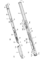
- FIG. 1 is a perspective view for explaining the internal configuration of the electronic pen of the embodiment.
- the electronic pen of this embodiment is composed of four major parts: an inner body 1, an electronic pen main body 2, a main body holder 3, and an elastic body holder 4.
- the inner body 1 is a tubular body having a tapered tip side, a hollow inside, a tip opening 11 provided at the tip, and a rear portion. A rear end opening 12 is provided at the end.
- the upper surface and the lower surface of the inner body 1 are formed in a plane shape, and a fitting protrusion 13a is provided on the rear end side of the upper surface.
- a fitting protrusion 13b is also provided on the rear end side of the lower surface at a position facing the fitting protrusion 13a.
- the electronic pen main body 2 is a part that realizes the electronic pen function. As shown in FIG. 1B, the appearance of the electronic pen main body 2 includes a core 21, a first sealing member 22, a coil 24, a pen pressure detecting portion 25, a second sealing member 26, a substrate holding portion 27, and a circuit. It is composed of a substrate 28 and a battery 29.
- the core body 21 has a rod shape, and is composed of a pen tip portion having a rounded tip and a shaft portion extending from the pen tip portion to the rear end side.
- the first sealing member 22 has a cup shape having a thickness formed of, for example, an elastic material such as synthetic rubber, and has an opening at the rear end surface and an opening at the front end surface as well as a core body. 21 can be inserted and removed.
- the first sealing member 22 is attached to the tip end side of the electronic pen main body portion 2 and is in close contact with the electronic pen main body portion 2 so as to cover the periphery of the tip end side.
- the coil 24 is formed by winding an insulating conductor around the side surface of the ferrite core 23, which is not visible in FIG. Both ends of the insulating lead wire constituting the coil 24 are stretched toward the rear end side and connected to a capacitor provided on the circuit board 28 described later to form a resonance circuit between the coil 24 and the capacitor.
- the pen pressure detecting unit 25 is configured to include a variable capacitance capacitor whose capacitance changes according to the pressing of the core body 21.
- This variable capacitance capacitor is connected in parallel to the resonant circuit formed by the coil 24 and the capacitor.
- information indicating the writing pressure applied to the core body 21 can be included in the magnetic field (signal) transmitted from the resonance circuit and transmitted.
- the second sealing member 26 is formed of a ring-shaped linear body having a certain thickness by, for example, an elastic material such as synthetic rubber, and has a tubular shape located at the rear stage of the pen pressure detection unit 25. It is provided in close contact with the outer edge of the formed substrate holding portion 27.
- the substrate holding portion 27 is provided in the rear stage of the second sealing member 26 so as to be connected to the pen pressure detecting portion 25, and the upper surface side is an opening except for the connecting portion with the pen pressure detecting unit 25. It has a shape.
- the board holding portion 27 includes a board area and a battery area. As shown in FIG. 1 (B), a circuit board 28 is mounted in the board area of the board holding portion 27, and a battery 29 is provided in the battery area. It will be installed.
- the circuit board 28 has an electronic circuit formed by various circuit components such as a capacitor for a resonance circuit connected in parallel to the coil 24, a control IC (Integrated Circuit), and a push switch (button switch) SW. It is a thing.
- the push switch SW is for realizing a so-called side switch provided on the side surface of the electronic pen and operated by the user. That is, different magnetic fields (signals) can be transmitted when the press switch SW is pressed and when it is not pressed.
- the electronic pen main body 2 is inserted from the pen tip side through the rear end opening 12, and is attached to the tip side of the electronic pen main body 2.
- the outer shape of the first sealing member 22 has the same shape as the corresponding inner portion of the inner body 1, but the size of the first sealing member 22 is the corresponding inner portion of the inner body 1. It is a little bigger than.
- the outer shape of the second sealing member 26 has the same shape as the corresponding inner portion of the inner body 1, but the size of the second sealing member 26 is larger for the second sealing member 26 than for the corresponding inner portion of the inner body 1. It's getting a little bigger.
- both the first sealing member 22 and the second sealing member 26 are made of an elastic material. Therefore, when the electronic pen main body 2 is inserted from the pen tip side through the rear end opening 12 of the inner body 1 and pushed to a fixed position, each of the first sealing member 22 and the second sealing member 26 becomes an inner body. It is in close contact with the inner wall at the corresponding position of 1. As a result, the space between the first sealing member 22 and the second sealing member 26 of the electronic pen main body 2 is sealed by the inner body 1 coming into close contact with the first sealing member 22 and the second sealing member 26. , Water, etc. can be prevented from entering. That is, a waterproof function can be added to the portion of the electronic pen main body 2 covered by the inner body 1.
- the circuit board 28 is covered with a resin to add a waterproof function to the circuit board 28 as well.
- a resin to add a waterproof function to the circuit board 28 as well.
- a liquid plastic UV bond
- a waterproof function is added to the entire circuit board area of the board holding portion 27. In this case, the thickness of the liquid plastic is reduced in the portion so that the push switch SW can be operated.
- the main body holder 3 holds the electronic pen main body 2, and includes connection plates 31a and 31b, a circuit board holding portion 32, a battery holding portion 33, a support portion 34, a pusher portion 35, and connecting arms 36a and 36b. Be prepared.
- the electronic pen main body 2 to which the inner body 1 is attached is inserted into the main body holder 3 from the connection plates 31a and 31b side, and the rear end surface 2T of the electronic pen main body 2 is the battery holding portion 33. It is made to come into contact with the bottom surface 33T.
- the connection plates 31a and 31b hold the electronic pen main body 2 by sandwiching the rear ends of the inner body 1 from above and below.
- connection plate 31a is provided with a fitting hole 31ah, and the connection plate 31b faces the fitting hole 31ah of the connection plate 31a, although not shown.
- a fitting hole 31bh is provided at the position. Therefore, the fitting protrusion 13a on the upper surface of the inner body 1 is fitted in the fitting hole 31ah of the connection plate 31a, and the fitting protrusion 13b on the lower surface of the inner body 1 is fitted in the fitting hole 31bh of the connection plate 31b. Fits. As a result, the electronic pen main body 2 to which the inner body 1 is attached does not easily come off from the main body holder 3.
- the portion between the circuit board holding portion 32 and the battery holding portion 33 has a half-pipe shape with an opening on the upper surface side.
- the support portion 34 is a portion formed in an arch shape at the boundary portion between the circuit board holding portion 32 and the battery holding portion 33. Therefore, the battery area of the substrate holding portion 27 of the electronic pen main body 2 passes under the support portion 34 and reaches the battery holding portion 33 on the rear side of the support portion 34. In this case, the board area of the board holding part 27 of the electronic pen main body 2 is located in the circuit board holding part 32 on the front side of the support part 34.
- the pusher portion 35 is a hollow portion extended from the support portion 34 toward the pen tip side, and passes directly above the push switch SW of the circuit board 28 of the electronic pen main body portion 2. As shown in FIG. 1C, the pusher portion 35 has an elongated plate shape including a shaft portion 35a and a pressing portion 35b. As described above, since the upper surface of the substrate holding portion 27 of the electronic pen main body 2 and the upper surface of the circuit board holding portion 32 of the main body holder 3 are both open, the pressing portion 35b of the pusher portion 35b. The pressing switch SW of the circuit board 28 can be pressed via the above.
- the pusher portion 35 acts as a leaf spring with the support portion 34 as a fulcrum. Therefore, when the upper surface of the pressing portion 35b of the pusher portion 35 is pressed, the pressing portion 35b is lowered to press the pressing switch SW of the circuit board 28. When the pressing on the upper surface of the pressing portion 35b is released, the pusher portion 35 acts as a leaf spring, the pressing portion 35b returns to the original position, and the pressing of the pressing switch SW is released. As described above, the pusher portion 35 is a member for constituting the side switch.
- the connecting arms 36a and 36b are portions that enable connection with the elastic body holder 4, and the holding portion 41 of the elastic body holder 4 described later is sandwiched from the left and right so that the main body holder 3 is attached to the elastic body holder 4. Connecting. Therefore, the electronic pen main body 2 to which the inner body 1 is mounted is held by the main body holder 3, and the main body holder 3 is connected to the elastic body holder 4.
- the elastic body holder 4 includes a holding portion 41 and a stretching portion 42. As shown in FIG. 1C, the holding portion 41 holds the coil spring 43 as an elastic body.
- the stretched portion 42 is a portion stretched from the rear end surface of the holding portion 41 to the rear end side, and is an internal structure of the electronic pen of this embodiment (inner body 1, electronic pen main body 2, main body holder 3, The purpose is to make the portion made of the elastic body holder 4) a predetermined length. Grooves are provided on the left and right side surfaces of the holding portion 41, and the connecting arms 36a and 36b of the main body holder 3 described above are fitted into these left and right grooves to fit the elastic holder 4 with respect to the elastic holder 4.
- the main body holder 3 is connected.
- the rear ends of the connecting arms 36a and 36b are provided with convex portions so as to project inward, and engage with the front ends of the left and right side groove portions of the holding portion 41.
- the main body holder 3 is prevented from being easily disengaged from the elastic body holder 4, and the main body holder 3 is pushed in and out of the elastic body holder 4 in the axial direction. That is, it is possible to slide and move (slide movement).
- a predetermined writing pressure for example, 300 g (grams) or more, is applied to the core body 21 of the electronic pen main body 2 mounted on the main body holder 3. It is assumed that pen pressure is applied. In this case, the main body holder 3 is pushed toward the elastic body holder 4, the coil spring 43 contracts, and the distance between the outer bottom surface 36T of the main body holder 3 and the inner bottom surface 41T of the holding portion 41 of the elastic body holder 4. Shrinks.
- the coil spring 43 is extended and the distance between the outer bottom surface 36T of the main body holder 3 and the inner bottom surface 41T of the holding portion 41 of the elastic body holder 4 is restored to the original distance.
- the coil spring 43 is interposed between the main body holder 3 and the elastic body holder 4, so that the main body holder 3 accommodating the electronic pen main body 2 can be accommodated according to the writing pressure applied to the core 21. Achieves the action of pushing in and back in the axial direction.
- the coil spring 43 does not contract.
- the predetermined writing pressure 300 g or more
- the coil spring 43 contracts, causing an action of retracting the core body 21 in the axial direction.
- FIG. 2 is a perspective view for explaining the electronic pen of the embodiment.
- FIG. 2A shows the internal structure of the electronic pen in a state where each part of the inner body 1, the electronic pen main body 2, the main body holder 3, and the elastic body holder 4 described with reference to FIG. 1 is connected. There is. That is, FIG. 2A shows a state in which the electronic pen main body 2 to which the inner body 1 is attached is attached to the main body holder 3, and the main body holder 3 is further connected to the elastic body holder 4. .
- FIG. 2B shows an electronic pen in a mode in which the internal structure of the electronic pen shown in FIG. 2A is housed in the outer housing 5 and is used by a user (end user). Shows the appearance.
- the outer housing 5 is a tubular body having a tapered pen tip side, and is provided with a tip opening at the tip of the pen tip and a rear end opening at the rear end side.
- the internal structure of the electronic pen shown in FIG. 2A is inserted from the rear end opening of the outer housing 5, so that the core 21 protrudes from the front end opening. In this state, the tip portion of the inner body 1 is in contact with the inner tip portion of the outer housing 5.
- a columnar rear end cap 7 is fitted into the rear end opening of the outer housing 5.
- the rear end cap 7 includes a fitting portion fitted inside the outer housing 5 and an exposed portion exposed to the outside.
- the outer diameter of the fitting portion of the rear end cap is slightly longer than the inner diameter of the outer housing 5, and the entire fitting portion is pushed into the outer housing 5 so as not to be easily disengaged.
- the outer diameter of the exposed portion of the rear end cap 7 is substantially the same as the outer diameter of the outer housing 5.
- the internal structure shown in FIG. 2A is attached to the outer housing 5 and used as an electronic pen.
- the coil spring sandwiched between the main body holder 3 and the elastic body holder 4 contracts, and the main body
- the core body 21 is housed in the outer housing by sliding the portion holder 3 toward the rear end side.
- the core body 21 is prevented from applying a writing pressure exceeding a predetermined value to the operation surface.
- the coil spring 43 expands and the core body 21 returns to the state of protruding from the tip opening of the outer housing 5.
- a side opening 5h is provided on the side surface of the outer housing 5.
- the side opening 5h is provided at a position corresponding to the pressing switch SW provided on the circuit board 28 of the electronic pen main body 2, and this position corresponds to the position of the pressing portion 35b of the pusher portion 35.
- the operation unit 6 is fitted into the side surface opening 5h.
- FIG. 3 is a diagram for explaining the configuration of the pen tip side of the electronic pen according to the embodiment, and is cut in the longitudinal direction of the electronic pen so as to be divided into a back side and a front side with the operation unit 6 on the upper side. However, it is a cross-sectional view when the front side is removed.
- the pen tip portion of the core body 21 of the electronic pen main body portion 2 is shown in FIG. (B), as shown in FIG. 3, the tip opening of the outer housing 5 is in a protruding state.
- the shaft portion of the core body 21 penetrates the through hole of the ferrite core 23, which is a cylindrical body, and reaches the pen pressure detecting portion 25.
- a coil 24 is formed on the side surface of the ferrite core 23 by winding an insulating conductor, and a first sealing member 22 is provided on the front end side of the coil 24 so as to cover the front end side of the ferrite core 23. Has been done.
- the pen pressure detecting unit 25 includes a pressing member 251, a first electrode 252, a dielectric 253, and a second electrode 254.
- the rear end side of the shaft portion of the core body 21 is inserted into the pressing member 251.
- a gap is provided between the first electrode 252 and one surface of the dielectric 253 facing the first electrode 252, via the pressing member 251 according to the writing pressure applied to the pen tip portion of the core body 21.
- the first electrode 252 approaches and moves away from the dielectric 253. Since the second electrode is provided on the other surface of the dielectric 253, it is based on the capacitance between the first electrode 252 and the second electrode 254 that changes according to the writing pressure. Pen pressure can be detected.
- a connecting member 2CN is provided at the rear stage of the second electrode 254.
- the connecting member 2CN connects the pen pressure detecting unit 25 and the substrate holding unit 27. That is, as shown in FIG. 3, the pen pressure detecting unit 25 is connected to the front stage of the connecting member 2CN, and the pen tip side tip portion of the substrate holding unit 27 is fitted to the rear stage of the connecting member 2CN.
- the pen pressure detecting unit 25 and the substrate holding unit 27 are connected via the connecting member 2CN.
- the pen tip side of the substrate holding portion 27 is formed in a cylindrical shape, and a ring-shaped second sealing member is provided around the side surface thereof in close contact with the periphery (outer edge) of the side surface. Further, as described above, the inner body 1 is attached to the pen tip side of the electronic pen main body 2.
- the pen tip side inside the inner body 1 is in close contact with the first sealing member, and the second sealing inside the inner body 1 is in close contact with the second sealing member. Adhere to the member.
- the portion of the inner body 1 consisting of the coil 24 and the pen pressure detecting portion 25 is sealed by the first sealing member 22 and the second sealing member 26 in close contact with the inner body 1 to be waterproof. The function is realized.
- the circuit board 28 and the battery 29 are mounted on the board holding portion 27.
- the upper surface side of the circuit board 28 is filled with a UV bond, and by irradiating with ultraviolet rays, the circuit board 28 is cured in close contact with the inner wall of the circuit board 28 and the substrate holding portion 27 to form a protective layer 28B, as described above.
- the waterproof function is realized for 28 parts of the circuit board.
- the circuit board 28 is a double-sided board in which circuit components are arranged on both sides. However, by filling the inside of the board holding portion 27 with a UV bond, water or the like can also be formed on the lower surface side of the circuit board 28. You can prevent the liquid from entering.
- a push switch SW is provided on the upper surface of the circuit board 28, but the thickness of the push switch SW portion is reduced so that the push operation can be performed and the protective layer 28B by the UB bond is thinned. ing.
- the main body holder 3 at least the upper surface side of the portion of the electronic pen main body 2 where the circuit board 28 is located is an opening, and the portion is in the shape of a half pipe. Further, as shown in FIG. 3, the main body holder 3 includes a pusher portion 35, which is an elongated plate-like body having a hollow extending from the support portion 34 toward the pen tip side.
- the pusher portion 35 includes a shaft portion 35a and a pressing portion 35b, and the pressing portion 35b is in a position where the pressing switch SW provided on the circuit board 28 can be pressed.
- the pressing portion 35b has a convex portion on the lower side, and the pressing portion 35 is pressed by pressing the operating portion 6 provided in the side opening portion 5h of the outer housing 5.
- the pressing switch SW can be pressed via the portion 35b.
- the pusher unit 35 acts as a leaf spring. Therefore, when the pressing applied to the operating portion 6 is released, the pusher portion 35 acts so as to return to the original state with the supporting portion 34 as a fulcrum. As a result, the pressing of the pressing switch SW is released, and the operation unit 6 is also pushed up to return to the original state.
- a side switch capable of reliably switching between a pressed / non-pressed state is realized with a simple configuration.
- the operation unit 6 is provided with a front end overhanging portion slightly overhanging toward the pen tip at the front end, and a rear end overhanging portion slightly overhanging toward the rear end at the rear end. Therefore, the operation unit 6 is prevented from easily coming off from the side opening of the outer housing 5. That is, in the operation unit 6, the front end overhanging portion and the rear end overhanging portion are merely engaged with the inner wall of the outer housing 5, and are merely mounted on the upper surface of the pressing portion 35b of the pusher portion 35.
- the operation unit 6 does not interfere with the sliding movement of the main body holder 3.
- the operation unit 6 can be attached by pushing it in.
- the operation unit 6 can be easily removed from the inside of the outer housing 5 by removing the internal structure shown in FIG. 2 (A) from the outer housing 5. It is possible to remove it.
- FIG. 4 is a diagram for explaining a state before and after an excessive writing pressure is applied to the electronic pen of the embodiment, with the side on which the operation unit 6 is located as the upper side. It is sectional drawing in the case of cutting up and down in the longitudinal direction with the opposite side as the lower side, and removing the upper side.
- FIG. 4 (B) shows the state of the core body 21. It shows a state in which a writing pressure of 300 g or more is applied to the pen tip.
- the core body 21 is as shown in FIG. 4 (A).
- the state in which the pen tip portion of 21 protrudes from the tip opening of the outer housing 5 is maintained. Therefore, when the electronic pen of this embodiment is used on the operation surface of the foldable terminal, it can function normally as an electronic pen if the writing pressure is less than 300 g.
- the coil spring 43 begins to contract, and the main body holder 3 to which the electronic pen main body 2 is attached gradually moves to the rear end side.
- the pen tip portion of the core body 21 enters the inside of the outer housing 5.
- a writing pressure of 300 g or more is not applied to the operation surface.
- the pen tip of the core 21 is housed in the outer housing 5 as shown in FIG. 4 (B), and the outer casing is provided. It will not protrude from the tip opening of the body 5.
- the pen tip portion of the core body 21 prevents the writing pressure of 300 g or more from being applied to a very narrow range of the operation surface. Therefore, the operation surface of the foldable terminal, which cannot be provided with a strong protective layer such as tempered glass, is not damaged by excessive writing pressure applied through the pen tip portion of the core body 21. can.
- the coil spring 43 expands and can return to the state shown in FIG. 4 (A).
- an internal structure including an inner body 1, an electronic pen main body 2, a main body holder 3, and an elastic body holder 4 is provided.
- the body can be slid and moved to the rear end side by a distance ⁇ minutes in the outer housing 5.
- the main body holder 3 to which the electronic pen main body 2 is mounted slides and moves according to the writing pressure applied to the pen tip of the core 21, the inside mounted on the electronic pen main body 2 No physical change occurs in the body 1 portion or the protective layer 28B portion on the circuit board 28. Therefore, even if the internal structure slides and moves, the waterproof function of the inner body 1 portion and the waterproof function of the protective layer 28B provided on the circuit board 28 are not deteriorated or lost.
- the coil 24 and the pen pressure detecting unit 25 can be provided with a waterproof function by the inner body 1, the first sealing member 22, and the second sealing member 26. Further, the waterproof function can be realized by providing the protective layer 28B by UV bond on the circuit board 28 portion. These waterproof functions are not affected even if the main body holder 3 to which the electronic pen main body 2 is mounted slides and moves according to the writing pressure applied to the pen tip of the core 21, and is said to be the same. The waterproof function of the part will not be deteriorated or lost. Therefore, it is possible to add a waterproof function and realize a suitable electronic pen for use in a foldable terminal.
- the elastic body holder 4 is provided with the stretched portion 42, but the present invention is not limited to this.
- the function of the stretched portion 42 is to increase the length of the fitting portion of the rear end cap 7, or to hold the outer housing 5 from the front stage portion for accommodating the internal structure and the internal accommodating body from the rear end side. It is also possible to have a configuration that is divided into two parts, that is, the rear part.
- the coil spring 43 is used as the elastic body located between the main body holder 3 and the elastic body holder 4, but the present invention is not limited to this.
- various elastic bodies capable of functioning similarly to the coil spring 43 such as synthetic rubber or sponge can be used.
- the front and rear overhanging portions engage with the front and rear inner walls of the side opening 5h of the outer housing 5 from the outer housing 5. I tried not to come off, but it is not limited to this.
- an engaging portion protruding portion having a portion protruding with respect to the direction in which the lower side intersects the axial direction is provided corresponding to the slit of the pressing portion 35b.
Abstract
Provided is an electronic pen that is provided with a waterproof function and is suitable for use with foldable terminals. A space between a first sealing member (22) and a second sealing member (26) of an electronic pen body part (2) is sealed by an inner body (1) closely adhering to the first sealing member (22) and the second sealing member (26), and as result thereof, a waterproof function is realized in said portion. Further, the electronic pen body part (2) and the inner body (1) are integrated and can be moved together. Due to this configuration, foldable terminal counter-measures can be easily and sufficiently taken.
Description
この発明は、例えば、タブレットPC(Personal Computer)などの電子機器に搭載された位置検出装置に対して、座標を指示することにより情報の入力を可能にする電子ペンに関する。
The present invention relates to an electronic pen that enables input of information by instructing coordinates to a position detecting device mounted on an electronic device such as a tablet PC (Personal Computer), for example.
例えば、タブレットPC(Personal Computer)やスマートフォンなどと呼ばれる高機能携帯電話端末などの電子機器においては、搭載された位置検出装置を通じて、より細かな描画入力を行うために、電子ペンによる指示入力が可能にされたものがある。携帯されて利用されることが多いタブレットPCや高機能電話端末での利用態様に鑑み、電子ペンについても細型化し、携帯により適したものとすることが考えられている。
For example, in electronic devices such as high-performance mobile phone terminals called tablet PCs (Personal Computers) and smartphones, it is possible to input instructions with an electronic pen in order to perform more detailed drawing input through the built-in position detection device. There is something that has been made. In view of the usage mode in tablet PCs and high-performance telephone terminals, which are often carried and used, it is considered that the electronic pen is also miniaturized to be more suitable for carrying.
また、タブレットPCや高機能電話端末などの電子機器や電子ペンは、雨天時の屋外や海、川、湖沼、プールなどの水辺といった、水による影響を受けやすい環境下で使用されることも多くなってきている。このため、当該電子機器と共に、電子ペンについても防水対策の必要性が重要視されるようになってきている。電子ペンについての防水対策については、例えば後に記す特許文献1~3に開示されているものがある。
In addition, electronic devices such as tablet PCs and high-performance telephone terminals and electronic pens are often used outdoors in rainy weather or in water-sensitive environments such as the sea, rivers, lakes, and pools. It has become to. For this reason, the need for waterproof measures for electronic pens as well as the electronic devices is becoming more important. As for the waterproof measures for the electronic pen, for example, there are those disclosed in Patent Documents 1 to 3 described later.
特許文献1には、コイルや回路基板などの電子ペンの重要部品の全体をシールドするという全体シーリングを行う技術が開示されている。特許文献2には、電子ペン機能を実現する構成部材等が収納された内部筐体内の中空部分に樹脂を充填して、防水機能を付加する技術が開示されている。特許文献3には、筐体内部のペン先側や回路基板接続部分に、防水用の弾性部材(キャップ部材やシーリング部材)を設けて、外部からの水等の侵入を防止する技術が開示されている。
Patent Document 1 discloses a technique for performing overall sealing by shielding the entire important component of an electronic pen such as a coil and a circuit board. Patent Document 2 discloses a technique of filling a hollow portion in an internal housing containing a component for realizing an electronic pen function with a resin to add a waterproof function. Patent Document 3 discloses a technique of providing a waterproof elastic member (cap member or sealing member) on the pen tip side inside the housing or on the circuit board connection portion to prevent water or the like from entering from the outside. ing.
上述した特許文献1~3に開示された技術は、電子ペンに防水機能を付加する技術として有用なものである。しかし、電子ペンに対しては、防水機能だけでなく、フォルダブル端末などと呼ばれる折り畳み式の携帯端末に対して使用するものとして、より適したものにしたいとする要求がある。ファルダブル端末は、折り畳み式であるため、従来の携帯端末のように表示画面上に強化ガラスなどの硬質の保護層を設けることができない。
The techniques disclosed in Patent Documents 1 to 3 described above are useful as techniques for adding a waterproof function to an electronic pen. However, there is a demand for electronic pens not only to have a waterproof function but also to be more suitable for use in foldable mobile terminals called foldable terminals and the like. Since the fal double terminal is a foldable type, it is not possible to provide a hard protective layer such as tempered glass on the display screen as in a conventional mobile terminal.
そこで、電子ペンの芯体により、フォルダブル端末の表示画面を傷付けることが無いように、電子ペンの芯体がフォルダブル端末の表示画面にして過度の筆圧をかけることが無いように対策をする必要がある。この場合、上述した特許文献1~3に記載された防水対策技術の場合、芯体は筆圧に応じて多少の摺動移動は可能であるが、芯体以外の電子ペン機能を実現する部分は、筐体内に固定されてしまう。このため、フォルダブル端末用の対策を簡単かつ十分に施せない。
Therefore, to prevent the core of the electronic pen from damaging the display screen of the foldable terminal, take measures to prevent the core of the electronic pen from being used as the display screen of the foldable terminal and applying excessive pen pressure. There is a need to. In this case, in the case of the waterproof measures technology described in Patent Documents 1 to 3 described above, the core body can slide and move to some extent according to the writing pressure, but the portion that realizes the electronic pen function other than the core body. Will be fixed inside the housing. Therefore, it is not possible to easily and sufficiently take measures for foldable terminals.
以上のことに鑑み、この発明は、防水機能を備えると共に、フォルダブル端末に対して用いて好適な電子ペンを提供することを目的とする。
In view of the above, it is an object of the present invention to provide a waterproof function and to provide a suitable electronic pen for use in a foldable terminal.
上記課題を解決するため、
先端側の周囲を覆う第1シーリング部材と、先端から後端側に離れた位置に外縁に沿って設けられた第2シーリング部材とを備える電子ペン本体部と、
筒状体であって、前記電子ペン本体部の先端側が挿入されることにより、内壁面に対して、前記第1シーリング部材と前記第2シーリング部材とが密着する内側ボディと
を備えた電子ペンを提供する。 To solve the above problems
An electronic pen main body including a first sealing member that covers the periphery of the tip side and a second sealing member provided along the outer edge at a position away from the tip to the rear end side.
An electronic pen that is a tubular body and has an inner body in which the first sealing member and the second sealing member are in close contact with the inner wall surface by inserting the tip end side of the electronic pen main body. I will provide a.
この電子ペンによれば、電子ペン本体部の第1シーリング部材と第2シーリング部材との間は、これらのシーリング部材と内側ボディとが密着することによって密閉されて、当該部分に防水機能が付与される。また、電子ペン本体部と内側ボディとは一体となり、共に移動可能にされる。これにより、フォルダブル端末の対策についても、簡単かつ十分に施すことができるようにされる。
According to this electronic pen, the first sealing member and the second sealing member of the main body of the electronic pen are sealed by being in close contact with the sealing member and the inner body, and a waterproof function is imparted to the portion. Will be done. In addition, the electronic pen body and the inner body are integrated and can be moved together. This makes it possible to easily and sufficiently take measures for foldable terminals.
以下、図を参照しながら、この発明による電子ペンの一実施の形態について説明する。例えば、電磁誘導方式の電子ペンは、コイルとコンデンサとを接続して構成される共振回路を備え、位置検出装置との間で磁界の送受を行うことにより、位置指示や筆圧の通知を行う。このため、電磁誘導方式の電子ペンの場合には、ペン先側にコイルが設けられるが、このコイル部分が水などで濡れると電気的な特性に変化が生じてしまうために、当該コイル部分には防水対策を施す必要が生じる。
Hereinafter, an embodiment of the electronic pen according to the present invention will be described with reference to the drawings. For example, an electromagnetic induction type electronic pen is provided with a resonance circuit configured by connecting a coil and a capacitor, and sends and receives a magnetic field to and from a position detection device to indicate a position and notify a pen pressure. .. For this reason, in the case of an electromagnetic induction type electronic pen, a coil is provided on the pen tip side, but if this coil part gets wet with water or the like, the electrical characteristics will change, so the coil part will change. Will need to be waterproofed.
また、アクティブ静電容量方式の電子ペンの場合には、バッテリ充電用のコイルを搭載する場合があり、当該コイル部分に対して防水対策を施す必要が生じる。このように、電子ペンには種々の方式のものがあり、そのそれぞれにおいて、防水対策を講じる必要性が高まっている。この発明は、防水対策を施すべき箇所のある種々の電子ペンに対して適用可能である。以下においては、説明を簡単するため、この発明を電磁誘導方式の電子ペンに適用した場合を例にして説明する。
Also, in the case of an active capacitance type electronic pen, a coil for charging the battery may be mounted, and it will be necessary to take waterproof measures for the coil part. As described above, there are various types of electronic pens, and there is an increasing need to take waterproof measures for each of them. The present invention is applicable to various electronic pens in which waterproof measures should be taken. In the following, for the sake of simplicity, the case where the present invention is applied to an electromagnetic induction type electronic pen will be described as an example.
図1は、実施の形態の電子ペンの内部構成を説明するための斜視図である。図1に示すように、この実施の形態の電子ペンは、内側ボディ1、電子ペン本体部2、本体部ホルダ3、弾性体ホルダ4の大きく4つの部分からなる。内側ボディ1は、図1(A)に示すように、先端側が先細り(テーパー形状)となった筒状体であり、内部は中空であって、先端には先端開口部11が設けられ、後端には後端開口部12が設けられている。内側ボディ1は、その上面と下面とが平面状に形成されており、上面後端側には嵌合突起13aが設けられている。なお、図1(A)においては見えないが、下面後端側にも、嵌合突起13aと対向する位置に嵌合突起13bが設けられている。
FIG. 1 is a perspective view for explaining the internal configuration of the electronic pen of the embodiment. As shown in FIG. 1, the electronic pen of this embodiment is composed of four major parts: an inner body 1, an electronic pen main body 2, a main body holder 3, and an elastic body holder 4. As shown in FIG. 1A, the inner body 1 is a tubular body having a tapered tip side, a hollow inside, a tip opening 11 provided at the tip, and a rear portion. A rear end opening 12 is provided at the end. The upper surface and the lower surface of the inner body 1 are formed in a plane shape, and a fitting protrusion 13a is provided on the rear end side of the upper surface. Although not visible in FIG. 1A, a fitting protrusion 13b is also provided on the rear end side of the lower surface at a position facing the fitting protrusion 13a.
電子ペン本体部2は、電子ペン機能を実現する部分である。電子ペン本体部2の外観は、図1(B)に示すように、芯体21、第1シーリング部材22、コイル24、筆圧検出部25、第2シーリング部材26、基板保持部27、回路基板28、バッテリ29からなる。芯体21は、棒状のものであり、先端が丸められたペン先部とペン先部から後端側に延伸された軸部からなる。
The electronic pen main body 2 is a part that realizes the electronic pen function. As shown in FIG. 1B, the appearance of the electronic pen main body 2 includes a core 21, a first sealing member 22, a coil 24, a pen pressure detecting portion 25, a second sealing member 26, a substrate holding portion 27, and a circuit. It is composed of a substrate 28 and a battery 29. The core body 21 has a rod shape, and is composed of a pen tip portion having a rounded tip and a shaft portion extending from the pen tip portion to the rear end side.
第1シーリング部材22は、例えば、合成ゴムなどの弾性材料により形成された厚みを有するカップ形状のものであり、後端面が開口になっていると共に、前端面にも開口が設けられ、芯体21の挿抜が可能になっている。第1シーリング部材22は、電子ペン本体部2の先端側に装着されて、先端側の周囲を覆うように電子ペン本体部2と密着する。コイル24は、図1においては見えないフェライトコア23の側面に絶縁導線を巻回することにより形成されているものである。コイル24を構成する絶縁導線の両端は、後端側に引き伸ばされて、後述する回路基板28に設けられているコンデンサに接続されることにより、コイル24とコンデンサとで共振回路を形成する。
The first sealing member 22 has a cup shape having a thickness formed of, for example, an elastic material such as synthetic rubber, and has an opening at the rear end surface and an opening at the front end surface as well as a core body. 21 can be inserted and removed. The first sealing member 22 is attached to the tip end side of the electronic pen main body portion 2 and is in close contact with the electronic pen main body portion 2 so as to cover the periphery of the tip end side. The coil 24 is formed by winding an insulating conductor around the side surface of the ferrite core 23, which is not visible in FIG. Both ends of the insulating lead wire constituting the coil 24 are stretched toward the rear end side and connected to a capacitor provided on the circuit board 28 described later to form a resonance circuit between the coil 24 and the capacitor.
筆圧検出部25は、芯体21の押圧に応じて静電容量が変化する可変容量コンデンサを内部に備えて構成されている。この可変容量コンデンサは、コイル24とコンデンサとで形成される共振回路に対して並列に接続される。これにより、芯体21にかかっている筆圧を示す情報も、当該共振回路から送信する磁界(信号)に含めて送信できるようにされる。第2シーリング部材26は、例えば、合成ゴムなどの弾性材料によりある程度の太さを持った線状体がリング状に形成されたものであり、筆圧検出部25の後段に位置する筒状に形成されている基板保持部27の外縁に沿って密着して設けられている。
The pen pressure detecting unit 25 is configured to include a variable capacitance capacitor whose capacitance changes according to the pressing of the core body 21. This variable capacitance capacitor is connected in parallel to the resonant circuit formed by the coil 24 and the capacitor. As a result, information indicating the writing pressure applied to the core body 21 can be included in the magnetic field (signal) transmitted from the resonance circuit and transmitted. The second sealing member 26 is formed of a ring-shaped linear body having a certain thickness by, for example, an elastic material such as synthetic rubber, and has a tubular shape located at the rear stage of the pen pressure detection unit 25. It is provided in close contact with the outer edge of the formed substrate holding portion 27.
基板保持部27は、第2シーリング部材26の後段に筆圧検出部25に対して接続するようにして設けられ、筆圧検出部25との接続部分を除いて上面側が開口となったハーフパイプ形状のものである。基板保持部27は、基板エリアとバッテリエリアとを備え、図1(B)に示したように、基板保持部27の基板エリアには回路基板28が搭載され、バッテリエリアには、バッテリ29が搭載される。
The substrate holding portion 27 is provided in the rear stage of the second sealing member 26 so as to be connected to the pen pressure detecting portion 25, and the upper surface side is an opening except for the connecting portion with the pen pressure detecting unit 25. It has a shape. The board holding portion 27 includes a board area and a battery area. As shown in FIG. 1 (B), a circuit board 28 is mounted in the board area of the board holding portion 27, and a battery 29 is provided in the battery area. It will be installed.
回路基板28は、コイル24に対して並列に接続される共振回路用のコンデンサ、制御用IC(Integrated Circuit)、押下スイッチ(釦スイッチ)SWなどの種々の回路部品によって電子回路が形成されているものである。なお、押下スイッチSWは、電子ペンの側面に設けられて使用者によって操作される、いわゆるサイドスイッチを実現するためのものである。すなわち、押下スイッチSWを押下しているときと、していないときとで、異なる磁界(信号)の送出ができるようになっている。
The circuit board 28 has an electronic circuit formed by various circuit components such as a capacitor for a resonance circuit connected in parallel to the coil 24, a control IC (Integrated Circuit), and a push switch (button switch) SW. It is a thing. The push switch SW is for realizing a so-called side switch provided on the side surface of the electronic pen and operated by the user. That is, different magnetic fields (signals) can be transmitted when the press switch SW is pressed and when it is not pressed.
なお、この実施の形態の電子ペンは、上述もしたように電磁誘導方式のものであり、磁界の作用によりコイルに電流が発生して動作するので、基本的は駆動電源を供給するバッテリは必要ない。しかし、この実施の形態の電子ペンは、例えば、ブルートゥース(登録商標)方式の通信回路などの駆動電源の供給が必要な回路部を備えているため、これらの回路部に駆動電源を供給するためのバッテリ29が搭載されている。当該通信回路は、例えば、電子ペンに関する情報を、位置検出装置を備えた端末側に通知するなどのための使用されるものである。
As described above, the electronic pen of this embodiment is of the electromagnetic induction type, and operates by generating an electric current in the coil due to the action of a magnetic field. Therefore, a battery for supplying a drive power source is basically required. not. However, since the electronic pen of this embodiment includes circuit units that need to be supplied with a drive power source such as a Bluetooth (registered trademark) type communication circuit, the drive power supply is supplied to these circuit units. Battery 29 is installed. The communication circuit is used, for example, to notify a terminal provided with a position detecting device of information about an electronic pen.
内側ボディ1は、後端開口部12より電子ペン本体部2がペン先側から挿入されて、電子ペン本体部2の先端側に装着される。この場合、第1シーリング部材22の外形は、内側ボディ1の対応する内側部分と同様の形状のものであるが、そのサイズは、第1シーリング部材22の方が内側ボディ1の対応する内側部分よりもやや大きくなっている。同様に、第2シーリング部材26の外形は、内側ボディ1の対応する内側部分と同じ形状であるが、そのサイズは、第2シーリング部材26の方が、内側ボディ1の対応する内側部分よりもやや大きくなっている。
In the inner body 1, the electronic pen main body 2 is inserted from the pen tip side through the rear end opening 12, and is attached to the tip side of the electronic pen main body 2. In this case, the outer shape of the first sealing member 22 has the same shape as the corresponding inner portion of the inner body 1, but the size of the first sealing member 22 is the corresponding inner portion of the inner body 1. It is a little bigger than. Similarly, the outer shape of the second sealing member 26 has the same shape as the corresponding inner portion of the inner body 1, but the size of the second sealing member 26 is larger for the second sealing member 26 than for the corresponding inner portion of the inner body 1. It's getting a little bigger.
上述したように、第1シーリング部材22と第2シーリング部材26は、いずれも弾性材料により形成されている。このため、内側ボディ1の後端開口部12より電子ペン本体部2をペン先側から挿入し、定位置まで押し込むと、第1シーリング部材22と第2シーリング部材26とのそれぞれが、内側ボディ1の対応する位置の内壁と密着する。これにより、電子ペン本体部2の第1シーリング部材22から第2シーリング部材26までの間は、第1シーリング部材22と第2シーリング部材26に対して、内側ボディ1が密着することにより密閉され、水等の浸入を防止できる。すなわち、電子ペン本体部2の内側ボディ1によって覆われた部分について防水機能を付加できる。
As described above, both the first sealing member 22 and the second sealing member 26 are made of an elastic material. Therefore, when the electronic pen main body 2 is inserted from the pen tip side through the rear end opening 12 of the inner body 1 and pushed to a fixed position, each of the first sealing member 22 and the second sealing member 26 becomes an inner body. It is in close contact with the inner wall at the corresponding position of 1. As a result, the space between the first sealing member 22 and the second sealing member 26 of the electronic pen main body 2 is sealed by the inner body 1 coming into close contact with the first sealing member 22 and the second sealing member 26. , Water, etc. can be prevented from entering. That is, a waterproof function can be added to the portion of the electronic pen main body 2 covered by the inner body 1.
また、回路基板28部分についても防水対策を施す必要がある。しかし、内側ボディ1を後端側に延伸するようにした場合には、押下スイッチSWの押下操作ができなくなってしまう。そこで、この実施の形態では、回路基板28上を樹脂で覆うようにすることで、回路基板28部分についても防水機能を付加している。具体的には、後述もするが、紫外線で硬化する液体プラスチック(UVボンド)で、回路基板28上を覆い、かつ、基板保持部27内を満たすようにし、紫外線を照射して硬化させることにより、基板保持部27の回路基板エリア全体について防水機能を付加している。この場合、押下スイッチSWの操作は可能なように、当該部分は液体プラスチックの厚みが薄くなるようにされる。
It is also necessary to take waterproof measures for the 28 parts of the circuit board. However, when the inner body 1 is extended toward the rear end side, the pressing operation of the pressing switch SW cannot be performed. Therefore, in this embodiment, the circuit board 28 is covered with a resin to add a waterproof function to the circuit board 28 as well. Specifically, as will be described later, by covering the circuit board 28 with a liquid plastic (UV bond) that is cured by ultraviolet rays and filling the inside of the substrate holding portion 27, and irradiating the substrate with ultraviolet rays to cure the circuit board 28. A waterproof function is added to the entire circuit board area of the board holding portion 27. In this case, the thickness of the liquid plastic is reduced in the portion so that the push switch SW can be operated.
本体部ホルダ3は、電子ペン本体部2を保持するものであり、接続板31a、31b、回路基板保持部32、バッテリ保持部33、支持部34、押し子部35、接続腕36a、36bを備える。本体部ホルダ3には、接続板31a、31b側より、内側ボディ1が装着された電子ペン本体部2が後端側より挿入され、電子ペン本体部2の後端面2Tがバッテリ保持部33の底面33Tに当接するようにされる。接続板31a、31bは、上下から内側ボディ1の後端部を挟み込むことで、電子ペン本体部2を保持する。
The main body holder 3 holds the electronic pen main body 2, and includes connection plates 31a and 31b, a circuit board holding portion 32, a battery holding portion 33, a support portion 34, a pusher portion 35, and connecting arms 36a and 36b. Be prepared. The electronic pen main body 2 to which the inner body 1 is attached is inserted into the main body holder 3 from the connection plates 31a and 31b side, and the rear end surface 2T of the electronic pen main body 2 is the battery holding portion 33. It is made to come into contact with the bottom surface 33T. The connection plates 31a and 31b hold the electronic pen main body 2 by sandwiching the rear ends of the inner body 1 from above and below.
なお、接続板31aには、図1(C)に示したように、嵌合穴31ahが設けられ、また、接続板31bには、図示しないが、接続板31aの嵌合穴31ahと対向する位置に嵌合穴31bhが設けられている。このため、接続板31aの嵌合穴31ahには、内側ボディ1の上面の嵌合突起13aが嵌合し、接続板31bの嵌合穴31bhには、内側ボディ1の下面の嵌合突起13bが嵌合する。これにより、内側ボディ1が装着された電子ペン本体部2が、簡単には本体部ホルダ3から外れることがない。
As shown in FIG. 1C, the connection plate 31a is provided with a fitting hole 31ah, and the connection plate 31b faces the fitting hole 31ah of the connection plate 31a, although not shown. A fitting hole 31bh is provided at the position. Therefore, the fitting protrusion 13a on the upper surface of the inner body 1 is fitted in the fitting hole 31ah of the connection plate 31a, and the fitting protrusion 13b on the lower surface of the inner body 1 is fitted in the fitting hole 31bh of the connection plate 31b. Fits. As a result, the electronic pen main body 2 to which the inner body 1 is attached does not easily come off from the main body holder 3.
回路基板保持部32とバッテリ保持部33との部分は、上面側が開口とされたハーフパイプ形状とされている。支持部34は、回路基板保持部32とバッテリ保持部33との境界部分にアーチ状に形成された部分である。従って、電子ペン本体部2の基板保持部27のバッテリエリアは、支持部34の下を通って、支持部34の後側のバッテリ保持部33に到達する。この場合、電子ペン本体部2の基板保持部27の基板エリアは、支持部34の前側の回路基板保持部32に位置する。
The portion between the circuit board holding portion 32 and the battery holding portion 33 has a half-pipe shape with an opening on the upper surface side. The support portion 34 is a portion formed in an arch shape at the boundary portion between the circuit board holding portion 32 and the battery holding portion 33. Therefore, the battery area of the substrate holding portion 27 of the electronic pen main body 2 passes under the support portion 34 and reaches the battery holding portion 33 on the rear side of the support portion 34. In this case, the board area of the board holding part 27 of the electronic pen main body 2 is located in the circuit board holding part 32 on the front side of the support part 34.
押し子部35は、支持部34から中空をペン先側に延伸されたものであり、電子ペン本体部2の回路基板28の押下スイッチSWの真上を通る。押し子部35は、図1(C)に示すように、軸部35aと押圧部35bとからなる細長の板状のものである。上述もしたように、電子ペン本体部2の基板保持部27の上面と本体部ホルダ3の回路基板保持部32の上面とは、共に開口となっているため、押し子部35の押圧部35bを介して、回路基板28の押下スイッチSWの押下操作が可能になる。
The pusher portion 35 is a hollow portion extended from the support portion 34 toward the pen tip side, and passes directly above the push switch SW of the circuit board 28 of the electronic pen main body portion 2. As shown in FIG. 1C, the pusher portion 35 has an elongated plate shape including a shaft portion 35a and a pressing portion 35b. As described above, since the upper surface of the substrate holding portion 27 of the electronic pen main body 2 and the upper surface of the circuit board holding portion 32 of the main body holder 3 are both open, the pressing portion 35b of the pusher portion 35b. The pressing switch SW of the circuit board 28 can be pressed via the above.
図1(C)に示したように、押し子部35の後端は、支持部34に固定されている。このため、押し子部35は、支持部34を支点として板バネとして作用する。従って、押し子部35の押圧部35bの上面を押圧すれは、押圧部35bは下がって回路基板28の押下スイッチSWを押下する。押圧部35bの上面への押圧を解除すれば、押し子部35は板バネとして作用して、押圧部35bは元の位置に復帰し、押下スイッチSWの押下を解除する。このように、押し子部35は、サイドスイッチを構成するための部材である。
As shown in FIG. 1 (C), the rear end of the pusher portion 35 is fixed to the support portion 34. Therefore, the pusher portion 35 acts as a leaf spring with the support portion 34 as a fulcrum. Therefore, when the upper surface of the pressing portion 35b of the pusher portion 35 is pressed, the pressing portion 35b is lowered to press the pressing switch SW of the circuit board 28. When the pressing on the upper surface of the pressing portion 35b is released, the pusher portion 35 acts as a leaf spring, the pressing portion 35b returns to the original position, and the pressing of the pressing switch SW is released. As described above, the pusher portion 35 is a member for constituting the side switch.
接続腕36a、36bは、弾性体ホルダ4との接続を可能にする部分であり、後述する弾性体ホルダ4の保持部41を左右から挟み込むようにして、本体部ホルダ3を弾性体ホルダ4に接続する。従って、内側ボディ1が装着された電子ペン本体部2は、本体部ホルダ3に保持され、この本体部ホルダ3は、弾性体ホルダ4に接続される。
The connecting arms 36a and 36b are portions that enable connection with the elastic body holder 4, and the holding portion 41 of the elastic body holder 4 described later is sandwiched from the left and right so that the main body holder 3 is attached to the elastic body holder 4. Connecting. Therefore, the electronic pen main body 2 to which the inner body 1 is mounted is held by the main body holder 3, and the main body holder 3 is connected to the elastic body holder 4.
弾性体ホルダ4は、保持部41と延伸部42とを備える。保持部41には、図1(C)に示すように、弾性体としてのコイルバネ43が保持される。
延伸部42は、保持部41の後端面から後端側に延伸された部分であり、この実施の形態の電子ペンの内部構造体(内側ボディ1、電子ペン本体部2、本体部ホルダ3、弾性体ホルダ4からなる部分)を所定の長さにするためのものである。保持部41の左右の側面には、溝部が設けられており、これらの左右の溝部には、上述した本体部ホルダ3の接続腕36a、36bが嵌まり込むことにより、弾性体ホルダ4に対して、本体部ホルダ3が接続される。 Theelastic body holder 4 includes a holding portion 41 and a stretching portion 42. As shown in FIG. 1C, the holding portion 41 holds the coil spring 43 as an elastic body.
The stretchedportion 42 is a portion stretched from the rear end surface of the holding portion 41 to the rear end side, and is an internal structure of the electronic pen of this embodiment (inner body 1, electronic pen main body 2, main body holder 3, The purpose is to make the portion made of the elastic body holder 4) a predetermined length. Grooves are provided on the left and right side surfaces of the holding portion 41, and the connecting arms 36a and 36b of the main body holder 3 described above are fitted into these left and right grooves to fit the elastic holder 4 with respect to the elastic holder 4. The main body holder 3 is connected.
延伸部42は、保持部41の後端面から後端側に延伸された部分であり、この実施の形態の電子ペンの内部構造体(内側ボディ1、電子ペン本体部2、本体部ホルダ3、弾性体ホルダ4からなる部分)を所定の長さにするためのものである。保持部41の左右の側面には、溝部が設けられており、これらの左右の溝部には、上述した本体部ホルダ3の接続腕36a、36bが嵌まり込むことにより、弾性体ホルダ4に対して、本体部ホルダ3が接続される。 The
The stretched
接続腕36a、36bの後端部は、内側に突出するように凸部が設けられており、保持部41の左右の側面溝部の前端部と係合する。これにより、本体部ホルダ3が弾性体ホルダ4に対して容易に外れることがないようにされると共に、本体部ホルダ3が弾性体ホルダ4に対し、軸心方向に押し込まれたり、戻ったりすること、すなわち、摺動移動(スライド移動)することが可能になっている。弾性体ホルダ4に対して本体部ホルダ3を接続した状態では、図1(C)に示したように、本体部ホルダ3の外側底面36Tと弾性体ホルダ4の保持部41の内側底面41Tとでコイルバネ43を挟み込む。コイルバネ43は本体部ホルダ3と弾性体ホルダ4とが離れるように作用している。
The rear ends of the connecting arms 36a and 36b are provided with convex portions so as to project inward, and engage with the front ends of the left and right side groove portions of the holding portion 41. As a result, the main body holder 3 is prevented from being easily disengaged from the elastic body holder 4, and the main body holder 3 is pushed in and out of the elastic body holder 4 in the axial direction. That is, it is possible to slide and move (slide movement). When the main body holder 3 is connected to the elastic body holder 4, as shown in FIG. 1 (C), the outer bottom surface 36T of the main body holder 3 and the inner bottom surface 41T of the holding portion 41 of the elastic body holder 4 The coil spring 43 is sandwiched between the two. The coil spring 43 acts so that the main body holder 3 and the elastic body holder 4 are separated from each other.
しかし、弾性体ホルダ4の後端面4Tが固定された状態で、本体部ホルダ3に装着された電子ペン本体部2の芯体21に対して、所定の筆圧、例えば300g(グラム)以上の筆圧がかけられたとする。この場合、本体部ホルダ3は弾性体ホルダ4側に押され、コイルバネ43が収縮して、本体部ホルダ3の外側底面36Tと弾性体ホルダ4の保持部41の内側底面41Tとの間の距離が縮まる。また、300g以上の筆圧が掛からなくなれば、コイルバネ43が伸長して、本体部ホルダ3の外側底面36Tと弾性体ホルダ4の保持部41の内側底面41Tとの間の距離が元の距離に復帰する。
However, with the rear end surface 4T of the elastic body holder 4 fixed, a predetermined writing pressure, for example, 300 g (grams) or more, is applied to the core body 21 of the electronic pen main body 2 mounted on the main body holder 3. It is assumed that pen pressure is applied. In this case, the main body holder 3 is pushed toward the elastic body holder 4, the coil spring 43 contracts, and the distance between the outer bottom surface 36T of the main body holder 3 and the inner bottom surface 41T of the holding portion 41 of the elastic body holder 4. Shrinks. Further, when the writing pressure of 300 g or more is not applied, the coil spring 43 is extended and the distance between the outer bottom surface 36T of the main body holder 3 and the inner bottom surface 41T of the holding portion 41 of the elastic body holder 4 is restored to the original distance. Return.
このように、コイルバネ43は、本体部ホルダ3と弾性体ホルダ4との間に介在することにより、芯体21にかかる筆圧に応じて、電子ペン本体部2を収納した本体部ホルダ3が軸心方向に押し込まれたり、戻ったりする作用を実現する。この実施の形態において、電子ペン本体部2の芯体21にかかる筆圧が、所定の筆圧未満(例えば300g未満)であればコイルバネ43は収縮しない。しかし、芯体21にかかる筆圧が、当該所定の筆圧以上(300g以上)になるとコイルバネ43は収縮し、芯体21を軸心方向に引っ込める作用を生じさせる。
As described above, the coil spring 43 is interposed between the main body holder 3 and the elastic body holder 4, so that the main body holder 3 accommodating the electronic pen main body 2 can be accommodated according to the writing pressure applied to the core 21. Achieves the action of pushing in and back in the axial direction. In this embodiment, if the writing pressure applied to the core 21 of the electronic pen main body 2 is less than a predetermined writing pressure (for example, less than 300 g), the coil spring 43 does not contract. However, when the writing pressure applied to the core body 21 becomes equal to or higher than the predetermined writing pressure (300 g or more), the coil spring 43 contracts, causing an action of retracting the core body 21 in the axial direction.
図2は、実施の形態の電子ペンを説明するための斜視図である。図2(A)は、図1を用いて説明した内側ボディ1、電子ペン本体部2、本体部ホルダ3、弾性体ホルダ4の各部が接続された状態の電子ペンの内部構造体を示している。すなわち、図2(A)は、内側ボディ1が装着された電子ペン本体部2が本体部ホルダ3に装着され、更に、本体部ホルダ3が弾性体ホルダ4に接続された状態を示している。
FIG. 2 is a perspective view for explaining the electronic pen of the embodiment. FIG. 2A shows the internal structure of the electronic pen in a state where each part of the inner body 1, the electronic pen main body 2, the main body holder 3, and the elastic body holder 4 described with reference to FIG. 1 is connected. There is. That is, FIG. 2A shows a state in which the electronic pen main body 2 to which the inner body 1 is attached is attached to the main body holder 3, and the main body holder 3 is further connected to the elastic body holder 4. ..
図2(B)は、図2(A)に示した電子ペンの内部構造体が、外側筐体5内に収納されることにより、使用者(エンドユーザ)によって使用される態様の電子ペンの外観を示している。外側筐体5は、ペン先側が先細り(テーパー形状)となった筒状体であり、ペン先側先端には先端開口が設けられ、後端側には後端開口が設けられている。図2(A)に示した電子ペンの内部構造体は、外側筐体5の後端開口から挿入され、芯体21が先端開口から突出するようにされる。この状態のときに、内側ボディ1の先端部分は、外側筐体5の内側先端部分と当接した状態となる。
FIG. 2B shows an electronic pen in a mode in which the internal structure of the electronic pen shown in FIG. 2A is housed in the outer housing 5 and is used by a user (end user). Shows the appearance. The outer housing 5 is a tubular body having a tapered pen tip side, and is provided with a tip opening at the tip of the pen tip and a rear end opening at the rear end side. The internal structure of the electronic pen shown in FIG. 2A is inserted from the rear end opening of the outer housing 5, so that the core 21 protrudes from the front end opening. In this state, the tip portion of the inner body 1 is in contact with the inner tip portion of the outer housing 5.
更に、外側筐体5の後端開口には、柱状の後端キャップ7が嵌め込まれる。後端キャップ7は、外側筐体5の内部に嵌め込まれる嵌合部と外部に露呈する露呈部とからなる。後端キャップの嵌合部の外径は、外側筐体5の内径よりやや長くされており、その全体を外側筐体5内に押し込むことにより、容易に外れないようにされる。なお、後端キャップ7の露呈部の外径は、外側筐体5の外径とほぼ同じ長さとなっている。
Further, a columnar rear end cap 7 is fitted into the rear end opening of the outer housing 5. The rear end cap 7 includes a fitting portion fitted inside the outer housing 5 and an exposed portion exposed to the outside. The outer diameter of the fitting portion of the rear end cap is slightly longer than the inner diameter of the outer housing 5, and the entire fitting portion is pushed into the outer housing 5 so as not to be easily disengaged. The outer diameter of the exposed portion of the rear end cap 7 is substantially the same as the outer diameter of the outer housing 5.
外側筐体5に対して、後端キャップ7がきちんと嵌め込まれると、後端キャップの嵌合部の前端面と図2(A)に示した内部構造体の弾性体ホルダ4の延伸部42の後端面4Tとが当接した状態となる。これにより、図2(A)に示した内部構造体は、外側筐体5内において、外側筐体5の内側先端部分と後端キャップ7の嵌合部とによって挟み込まれ、外側筐体5内においてその位置が規制される。
When the rear end cap 7 is properly fitted to the outer housing 5, the front end surface of the fitting portion of the rear end cap and the stretched portion 42 of the elastic body holder 4 of the internal structure shown in FIG. 2 (A). The rear end surface 4T is in contact with the rear end surface 4T. As a result, the internal structure shown in FIG. 2A is sandwiched between the inner tip portion of the outer housing 5 and the fitting portion of the rear end cap 7 in the outer housing 5, and is inside the outer housing 5. The position is regulated in.
このようにして、図2(A)に示した内部構造体が、外側筐体5に装着されて、電子ペンとして使用される。この場合に、外側筐体5の先端開口から突出している芯体21に、所定値以上の筆圧がかかると、本体部ホルダ3と弾性体ホルダ4とに挟まれたコイルバネが収縮し、本体部ホルダ3が後端側に摺動移動することによって、芯体21が外側筐体内に収納される。これにより、芯体21が所定値以上の筆圧を操作面にかけることがないようにされる。なお、芯体21に所定値以上の筆圧が掛からなくなると、コイルバネ43は伸長して、芯体21は、外側筐体5の先端開口から突出した状態に復帰する。
In this way, the internal structure shown in FIG. 2A is attached to the outer housing 5 and used as an electronic pen. In this case, when a writing pressure of a predetermined value or more is applied to the core body 21 protruding from the tip opening of the outer housing 5, the coil spring sandwiched between the main body holder 3 and the elastic body holder 4 contracts, and the main body The core body 21 is housed in the outer housing by sliding the portion holder 3 toward the rear end side. As a result, the core body 21 is prevented from applying a writing pressure exceeding a predetermined value to the operation surface. When the writing pressure equal to or higher than the predetermined value is not applied to the core body 21, the coil spring 43 expands and the core body 21 returns to the state of protruding from the tip opening of the outer housing 5.
また、外側筐体5の側面には、側面開口部5hが設けられている。側面開口部5hは、電子ペン本体部2の回路基板28に設けられた押下スイッチSWに対応する位置に設けられており、この位置は、押し子部35の押圧部35bの位置に対応している。側面開口部5hには、操作部6が嵌め込まれる。これにより、使用者は、操作部6を押圧すると、押し子部35の押圧部35bを介して、回路基板28の押下スイッチSWを押下することができる。操作部6への押下操作を解除すれば、押し子部35の板バネ作用により、押圧部35bは元の位置に復帰し、これに応じて、操作部6も元の状態に復帰する。
Further, a side opening 5h is provided on the side surface of the outer housing 5. The side opening 5h is provided at a position corresponding to the pressing switch SW provided on the circuit board 28 of the electronic pen main body 2, and this position corresponds to the position of the pressing portion 35b of the pusher portion 35. There is. The operation unit 6 is fitted into the side surface opening 5h. As a result, when the user presses the operation unit 6, the user can press the pressing switch SW of the circuit board 28 via the pressing portion 35b of the pusher portion 35. When the pressing operation on the operating unit 6 is released, the pressing unit 35b returns to the original position due to the leaf spring action of the pusher unit 35, and the operating unit 6 also returns to the original state accordingly.
図3は、実施の形態の電子ペンのペン先側の構成を説明するための図であり、操作部6を上側にして、奥側と手前側とに分けるように電子ペンの長手方向に切断し、手前側を取り除いた場合の断面図である。この実施の形態の電子ペンは、図2(A)に示した内部構造体が、外側筐体5の装着された状態では、電子ペン本体部2の芯体21のペン先部が、図2(B)、図3に示したように外側筐体5の先端開口部が突出した状態になる。芯体21の軸部は、筒状体であるフェライトコア23の貫通孔を貫通し、筆圧検出部25に到達する。フェライトコア23の側面には、絶縁導線が巻回されることによりコイル24が形成されている、コイル24の前端側には、フェライトコア23の前端側を覆うように第1シーリング部材22が設けられている。
FIG. 3 is a diagram for explaining the configuration of the pen tip side of the electronic pen according to the embodiment, and is cut in the longitudinal direction of the electronic pen so as to be divided into a back side and a front side with the operation unit 6 on the upper side. However, it is a cross-sectional view when the front side is removed. In the electronic pen of this embodiment, when the internal structure shown in FIG. 2A is attached to the outer housing 5, the pen tip portion of the core body 21 of the electronic pen main body portion 2 is shown in FIG. (B), as shown in FIG. 3, the tip opening of the outer housing 5 is in a protruding state. The shaft portion of the core body 21 penetrates the through hole of the ferrite core 23, which is a cylindrical body, and reaches the pen pressure detecting portion 25. A coil 24 is formed on the side surface of the ferrite core 23 by winding an insulating conductor, and a first sealing member 22 is provided on the front end side of the coil 24 so as to cover the front end side of the ferrite core 23. Has been done.
筆圧検出部25は、押圧部材251と、第1の電極252と、誘電体253と、第2の電極254とからなる。押圧部材251には芯体21の軸部の後端側が差し込まれている。第1の電極252と、これに対向する誘電体253の一方の面との間には空隙が設けられており、芯体21のペン先部にかけられる筆圧に応じて、押圧部材251を介して、第1の電極252が誘電体253に近づいたり離れたりする。誘電体253の他方の面には、第2の電極が設けられているので、筆圧に応じて変化する第1の電極252と第2の電極254との間の静電容量に基づいて、筆圧の検出が可能になっている。
The pen pressure detecting unit 25 includes a pressing member 251, a first electrode 252, a dielectric 253, and a second electrode 254. The rear end side of the shaft portion of the core body 21 is inserted into the pressing member 251. A gap is provided between the first electrode 252 and one surface of the dielectric 253 facing the first electrode 252, via the pressing member 251 according to the writing pressure applied to the pen tip portion of the core body 21. The first electrode 252 approaches and moves away from the dielectric 253. Since the second electrode is provided on the other surface of the dielectric 253, it is based on the capacitance between the first electrode 252 and the second electrode 254 that changes according to the writing pressure. Pen pressure can be detected.
第2の電極254の後段には、接続部材2CNが設けられている。接続部材2CNは、筆圧検出部25と基板保持部27とを接続する。すなわち、図3に示すように、接続部材2CNの前段には筆圧検出部25が接続され、接続部材2CNの後段には、基板保持部27のペン先側先端部が嵌合することにより、接続部材2CNを介して、筆圧検出部25と基板保持部27とが接続される。基板保持部27のペン先側は筒状に形成されており、その側面周囲には、当該側面周囲(外縁)に密着して、リング状の第2シーリング部材が設けられている。また、上述もしたように、電子ペン本体部2のペン先側には内側ボディ1が装着されている。
A connecting member 2CN is provided at the rear stage of the second electrode 254. The connecting member 2CN connects the pen pressure detecting unit 25 and the substrate holding unit 27. That is, as shown in FIG. 3, the pen pressure detecting unit 25 is connected to the front stage of the connecting member 2CN, and the pen tip side tip portion of the substrate holding unit 27 is fitted to the rear stage of the connecting member 2CN. The pen pressure detecting unit 25 and the substrate holding unit 27 are connected via the connecting member 2CN. The pen tip side of the substrate holding portion 27 is formed in a cylindrical shape, and a ring-shaped second sealing member is provided around the side surface thereof in close contact with the periphery (outer edge) of the side surface. Further, as described above, the inner body 1 is attached to the pen tip side of the electronic pen main body 2.
この場合、上述もし、また、図3に示すように、内側ボディ1の内部のペン先側においては、第1シーリング部材と密着し、内側ボディ1の内部の後端側においては、第2シーリング部材と密着する。これにより、内側ボディ1の内のコイル24及び筆圧検出部25からなる部分は、内側ボディ1に対して、第1シーリング部材22と第2シーリング部材26とが密着するにより密閉されて、防水機能が実現されている。
In this case, as described above, and as shown in FIG. 3, the pen tip side inside the inner body 1 is in close contact with the first sealing member, and the second sealing inside the inner body 1 is in close contact with the second sealing member. Adhere to the member. As a result, the portion of the inner body 1 consisting of the coil 24 and the pen pressure detecting portion 25 is sealed by the first sealing member 22 and the second sealing member 26 in close contact with the inner body 1 to be waterproof. The function is realized.
基板保持部27には、回路基板28やバッテリ29が搭載される。回路基板28の上面側は、UVボンドにより満たされ、紫外線を照射することにより回路基板28や基板保持部27の内壁と密着した状態で硬化して保護層28Bが形成され、上述もしたように、回路基板28部分について防水機能が実現される。なお、回路基板28は、両面に回路部品が配置されて構成された両面基板であるが、基板保持部27内をUVボンドで満たすようにすることによって、回路基板28の下面側にも水等の液体が浸入しないようにできる。
The circuit board 28 and the battery 29 are mounted on the board holding portion 27. The upper surface side of the circuit board 28 is filled with a UV bond, and by irradiating with ultraviolet rays, the circuit board 28 is cured in close contact with the inner wall of the circuit board 28 and the substrate holding portion 27 to form a protective layer 28B, as described above. , The waterproof function is realized for 28 parts of the circuit board. The circuit board 28 is a double-sided board in which circuit components are arranged on both sides. However, by filling the inside of the board holding portion 27 with a UV bond, water or the like can also be formed on the lower surface side of the circuit board 28. You can prevent the liquid from entering.
なお、回路基板28の上面には、押下スイッチSWが設けられているが、押下スイッチSW部分は、押下操作が可能なように、UBボンドによる保護層28Bは、その厚みが薄くなるようにされている。本体部ホルダ3において、電子ペン本体部2の少なくとも回路基板28が位置する部分の上面側は開口とされ、当該部分はハーフパイプ形状とされている。また、本体部ホルダ3は、図3に示すように、支持部34から中空をペン先側に延伸された細長の板状体である押し子部35を備えている。
A push switch SW is provided on the upper surface of the circuit board 28, but the thickness of the push switch SW portion is reduced so that the push operation can be performed and the protective layer 28B by the UB bond is thinned. ing. In the main body holder 3, at least the upper surface side of the portion of the electronic pen main body 2 where the circuit board 28 is located is an opening, and the portion is in the shape of a half pipe. Further, as shown in FIG. 3, the main body holder 3 includes a pusher portion 35, which is an elongated plate-like body having a hollow extending from the support portion 34 toward the pen tip side.
押し子部35は、軸部35aと押圧部35bとからなるが、押圧部35bは、回路基板28上に設けられている押下スイッチSWを押下することが可能な位置にある。押圧部35bは、図3に示すように、下側に凸部を備えており、外側筐体5の側面開口部5hに設けられた操作部6を押下することにより、押し子部35の押圧部35bを介して押下スイッチSWを押下できる。
The pusher portion 35 includes a shaft portion 35a and a pressing portion 35b, and the pressing portion 35b is in a position where the pressing switch SW provided on the circuit board 28 can be pressed. As shown in FIG. 3, the pressing portion 35b has a convex portion on the lower side, and the pressing portion 35 is pressed by pressing the operating portion 6 provided in the side opening portion 5h of the outer housing 5. The pressing switch SW can be pressed via the portion 35b.
なお、操作部6に加えた押圧を解除すれば、押し子部35は板バネとして作用する。このため、操作部6に加えた押圧を解除すれば、押し子部35は、支持部34を支点として元の状態に戻るように作用する。これにより、押下スイッチSWへの押下を解除し、操作部6も押し上げて、元の状態に戻る。このように、この実施の形態の電子ペンの場合には、簡単な構成で確実に押下/非押下の状態を切り替えることが可能なサイドスイッチを実現している。
If the pressing applied to the operation unit 6 is released, the pusher unit 35 acts as a leaf spring. Therefore, when the pressing applied to the operating portion 6 is released, the pusher portion 35 acts so as to return to the original state with the supporting portion 34 as a fulcrum. As a result, the pressing of the pressing switch SW is released, and the operation unit 6 is also pushed up to return to the original state. As described above, in the case of the electronic pen of this embodiment, a side switch capable of reliably switching between a pressed / non-pressed state is realized with a simple configuration.
また、操作部6は、前端にはペン先に向かって若干張り出した前端張り出し部を備え、後端には後側に向かって若干張り出した後端張り出し部を備えている。このため、操作部6は、外側筐体5の側面開口から容易に外れないようにされる。すなわち、操作部6は、前端張り出し部と後端張り出し部とが、外側筐体5の内壁と係合するだけで、押し子部35の押圧部35bの上面に乗っているだけである。
Further, the operation unit 6 is provided with a front end overhanging portion slightly overhanging toward the pen tip at the front end, and a rear end overhanging portion slightly overhanging toward the rear end at the rear end. Therefore, the operation unit 6 is prevented from easily coming off from the side opening of the outer housing 5. That is, in the operation unit 6, the front end overhanging portion and the rear end overhanging portion are merely engaged with the inner wall of the outer housing 5, and are merely mounted on the upper surface of the pressing portion 35b of the pusher portion 35.
このため、上述したように、芯体21のペン先部に、所定値以上の筆圧が掛かることにより、電子ペン本体部2が装着された本体部ホルダ3が、電子ペンの後側に押し込まれても、操作部6が本体部ホルダ3の摺動移動の邪魔になることがない。なお、操作部6を外側筐体5の側面開口に対して装着する場合には、押し込むことにより装着可能である。また、操作部6を外側筐体5から取り外す場合には、外側筐体5から図2(A)に示した内部構成体を抜き取ることによって、操作部6は、外側筐体5の内側から簡単に取り外すことが可能である。
Therefore, as described above, when a writing pressure of a predetermined value or more is applied to the pen tip portion of the core body 21, the main body portion holder 3 to which the electronic pen main body portion 2 is attached is pushed into the rear side of the electronic pen. Even so, the operation unit 6 does not interfere with the sliding movement of the main body holder 3. When the operation unit 6 is attached to the side opening of the outer housing 5, it can be attached by pushing it in. Further, when the operation unit 6 is removed from the outer housing 5, the operation unit 6 can be easily removed from the inside of the outer housing 5 by removing the internal structure shown in FIG. 2 (A) from the outer housing 5. It is possible to remove it.
図4は、実施の形態の電子ペンに対して、過剰な筆圧がかけられる前とかけられた後の状態について説明するための図であり、操作部6が位置する側を上側とし、その反対側を下側として、長手方向の上下に切断し、上側を取り除いた場合の断面図である。図4において、図4(A)は、芯体21のペン先部に筆圧が加わっていない状態(筆圧=0g)の状態を示しており、図4(B)は、芯体21のペン先部に300g以上の筆圧が加わっている状態を示している。
FIG. 4 is a diagram for explaining a state before and after an excessive writing pressure is applied to the electronic pen of the embodiment, with the side on which the operation unit 6 is located as the upper side. It is sectional drawing in the case of cutting up and down in the longitudinal direction with the opposite side as the lower side, and removing the upper side. In FIG. 4, FIG. 4 (A) shows a state in which writing pressure is not applied to the pen tip portion of the core body 21 (writing pressure = 0 g), and FIG. 4 (B) shows the state of the core body 21. It shows a state in which a writing pressure of 300 g or more is applied to the pen tip.
この実施の形態の電子ペンの場合には、芯体21のペン先部にかかる筆圧が、0g以上、300g未満の範囲内であれば、図4(A)に示したように、芯体21のペン先部が外側筐体5の先端開口から突出した様態が維持される。従って、この実施の形態の電子ペンをフォルダブル端末の操作面上において用いた場合には、筆圧が300g未満であれば、電子ペンとして正常に機能させることができる。しかし、芯体21のペン先部にかかる筆圧が、300g以上になると、コイルバネ43が収縮し始め、電子ペン本体部2が装着された本体部ホルダ3が徐々に後端側に移動するようになり、芯体21のペン先部は、外側筐体5の内側に入っていく。
In the case of the electronic pen of this embodiment, if the writing pressure applied to the pen tip portion of the core body 21 is within the range of 0 g or more and less than 300 g, the core body is as shown in FIG. 4 (A). The state in which the pen tip portion of 21 protrudes from the tip opening of the outer housing 5 is maintained. Therefore, when the electronic pen of this embodiment is used on the operation surface of the foldable terminal, it can function normally as an electronic pen if the writing pressure is less than 300 g. However, when the writing pressure applied to the pen tip of the core 21 becomes 300 g or more, the coil spring 43 begins to contract, and the main body holder 3 to which the electronic pen main body 2 is attached gradually moves to the rear end side. The pen tip portion of the core body 21 enters the inside of the outer housing 5.
このような動作により、芯体21のペン先部によっては、操作面に対して300g以上の筆圧が掛からないようにされる。芯体21のペン先部にかかる筆圧が300g以上の所定値になると、図4(B)に示したように、芯体21のペン先部が外側筐体5内に収納され、外側筐体5の先端開口から突出しない状態となる。この場合、芯体21のペン先部によって、操作面のごく狭い範囲に300g以上の筆圧がかかることが防止される。従って、強化ガラス等の強固な保護層を設けることができないフォルダブル端末の操作面に対して、芯体21のペン先部を通じて過度の筆圧がかかることにより、損傷を与えることがないようにできる。また、芯体21のペン先部にかかる筆圧が、300g未満になれば、コイルバネ43は伸長し、図4(A)に示した状態に復帰できる。
By such an operation, depending on the pen tip portion of the core body 21, a writing pressure of 300 g or more is not applied to the operation surface. When the writing pressure applied to the pen tip of the core 21 reaches a predetermined value of 300 g or more, the pen tip of the core 21 is housed in the outer housing 5 as shown in FIG. 4 (B), and the outer casing is provided. It will not protrude from the tip opening of the body 5. In this case, the pen tip portion of the core body 21 prevents the writing pressure of 300 g or more from being applied to a very narrow range of the operation surface. Therefore, the operation surface of the foldable terminal, which cannot be provided with a strong protective layer such as tempered glass, is not damaged by excessive writing pressure applied through the pen tip portion of the core body 21. can. Further, when the writing pressure applied to the pen tip portion of the core body 21 becomes less than 300 g, the coil spring 43 expands and can return to the state shown in FIG. 4 (A).
なお、この実施の形態の電子ペンの場合には、図4において、点線を引いて示したように、内側ボディ1、電子ペン本体部2、本体部ホルダ3、弾性体ホルダ4からなる内部構造体を、外側筐体5内において距離α分後端側に摺動移動させることができる。このように、芯体21のペン先部にかかる筆圧に応じて、電子ペン本体部2が装着された本体部ホルダ3が摺動移動しても、電子ペン本体部2に装着された内側ボディ1部分や回路基板28上の保護層28B部分には、物理的な変化は生じない。このため、内部構造体が摺動移動しても、内側ボディ1部分の防水機能や回路基板28上に設けられた保護層28Bによる防水機能が劣化したり、失われたりすることはない。
In the case of the electronic pen of this embodiment, as shown by a dotted line in FIG. 4, an internal structure including an inner body 1, an electronic pen main body 2, a main body holder 3, and an elastic body holder 4 is provided. The body can be slid and moved to the rear end side by a distance α minutes in the outer housing 5. In this way, even if the main body holder 3 to which the electronic pen main body 2 is mounted slides and moves according to the writing pressure applied to the pen tip of the core 21, the inside mounted on the electronic pen main body 2 No physical change occurs in the body 1 portion or the protective layer 28B portion on the circuit board 28. Therefore, even if the internal structure slides and moves, the waterproof function of the inner body 1 portion and the waterproof function of the protective layer 28B provided on the circuit board 28 are not deteriorated or lost.
[実施の形態の効果]
上述した実施の形態の電子ペンは、コイル24及び筆圧検出部25の部分には、内側ボディ1と第1シーリング部材22と第2シーリング部材26とにより防水機能が実現できる。また、回路基板28部分には、UVボンドによる保護層28Bを設けることにより防水機能が実現できる。これらの防水機能は、芯体21のペン先部にかかる筆圧に応じて、電子ペン本体部2が装着された本体部ホルダ3が摺動移動しても、影響を受けることはなく、当該部分の防水機能が劣化したり、失われたりすることはない。従って、防水機能を付加すると共に、フォルダブル端末に用いて好適な電子ペンが実現できる。 [Effect of embodiment]
In the electronic pen of the above-described embodiment, thecoil 24 and the pen pressure detecting unit 25 can be provided with a waterproof function by the inner body 1, the first sealing member 22, and the second sealing member 26. Further, the waterproof function can be realized by providing the protective layer 28B by UV bond on the circuit board 28 portion. These waterproof functions are not affected even if the main body holder 3 to which the electronic pen main body 2 is mounted slides and moves according to the writing pressure applied to the pen tip of the core 21, and is said to be the same. The waterproof function of the part will not be deteriorated or lost. Therefore, it is possible to add a waterproof function and realize a suitable electronic pen for use in a foldable terminal.
上述した実施の形態の電子ペンは、コイル24及び筆圧検出部25の部分には、内側ボディ1と第1シーリング部材22と第2シーリング部材26とにより防水機能が実現できる。また、回路基板28部分には、UVボンドによる保護層28Bを設けることにより防水機能が実現できる。これらの防水機能は、芯体21のペン先部にかかる筆圧に応じて、電子ペン本体部2が装着された本体部ホルダ3が摺動移動しても、影響を受けることはなく、当該部分の防水機能が劣化したり、失われたりすることはない。従って、防水機能を付加すると共に、フォルダブル端末に用いて好適な電子ペンが実現できる。 [Effect of embodiment]
In the electronic pen of the above-described embodiment, the
[変形例]
上述した実施の形態の電子ペンの場合には、回路基板28上に保護層28Bを設けることにより、バッテリ29との接続部分も覆わるため、バッテリ29の部分には防水対策を施さなかったが、施すようにしてもよい。また、上述した実施の形態ン電子ペンでは、回路基板28部分について、UVボンドを用いて防水機能を付加したが、これに限るものではない。種々の樹脂素材を用いて、防水機能を付加することも可能である。 [Modification example]
In the case of the electronic pen of the above-described embodiment, since theprotective layer 28B is provided on the circuit board 28 to cover the connection portion with the battery 29, the battery 29 portion is not waterproofed. , May be applied. Further, in the above-described embodiment of the electronic pen, a waterproof function is added to the circuit board 28 portion by using a UV bond, but the present invention is not limited to this. It is also possible to add a waterproof function by using various resin materials.
上述した実施の形態の電子ペンの場合には、回路基板28上に保護層28Bを設けることにより、バッテリ29との接続部分も覆わるため、バッテリ29の部分には防水対策を施さなかったが、施すようにしてもよい。また、上述した実施の形態ン電子ペンでは、回路基板28部分について、UVボンドを用いて防水機能を付加したが、これに限るものではない。種々の樹脂素材を用いて、防水機能を付加することも可能である。 [Modification example]
In the case of the electronic pen of the above-described embodiment, since the
また、上述した実施の形態の電子ペンにおいては、弾性体ホルダ4が、延伸部42を備えるようにしたが、これに限るものではない。延伸部42の機能を、後端キャップ7の嵌合部の長さを長くしたり、外側筐体5を、内部構造体を収納する前段部と、内部収納体を後端側から押さえるようにする後段部との2つに分けた構成にしたりすることも可能である。
Further, in the electronic pen of the above-described embodiment, the elastic body holder 4 is provided with the stretched portion 42, but the present invention is not limited to this. The function of the stretched portion 42 is to increase the length of the fitting portion of the rear end cap 7, or to hold the outer housing 5 from the front stage portion for accommodating the internal structure and the internal accommodating body from the rear end side. It is also possible to have a configuration that is divided into two parts, that is, the rear part.
また、上述した実施の形態の電子ペンにおいては、本体部ホルダ3と弾性体ホルダ4との間に位置する弾性体は、コイルバネ43を用いるようにしたが、これに限るものではない。例えば、合成ゴムやスポンジなどのコイルバネ43と同様に機能することが可能な種々の弾性体を用いることができる。
Further, in the electronic pen of the above-described embodiment, the coil spring 43 is used as the elastic body located between the main body holder 3 and the elastic body holder 4, but the present invention is not limited to this. For example, various elastic bodies capable of functioning similarly to the coil spring 43 such as synthetic rubber or sponge can be used.
また、上述した実施の形態の電子ペンにおいては、操作部6は、前後に張り出した張り出し部が、外側筐体5の側面開口部5hの前後の内壁に係合して、外側筐体5から外れないようにしたが、これに限るものではない。押し子部35の押圧部35b部分に、軸心方向(電子ペンの長手方向)に沿って、例えば逆T字型のように、下側が軸心方向と交差する方向に対して張り出した部分を有するスリットを設けておく。一方、操作部6の下側には、押圧部35bのスリットに対応して、下側が軸心方向と交差する方向に対して張り出した部分を有する係合部(突起部)を設けておく。
Further, in the electronic pen of the above-described embodiment, in the operation unit 6, the front and rear overhanging portions engage with the front and rear inner walls of the side opening 5h of the outer housing 5 from the outer housing 5. I tried not to come off, but it is not limited to this. A portion protruding from the pressing portion 35b of the pusher portion 35 along the axial direction (longitudinal direction of the electronic pen) with respect to the direction in which the lower side intersects the axial direction, for example, in an inverted T shape. Provide a slit to have. On the other hand, on the lower side of the operating portion 6, an engaging portion (protruding portion) having a portion protruding with respect to the direction in which the lower side intersects the axial direction is provided corresponding to the slit of the pressing portion 35b.
この場合、外側筐体5に図2(b)に示した内部構造体を装着する時に、接続板31aが側面開口部5hを通過したら、操作部6を側面開口部5hに嵌合させ、内部構造体をペン先側に押し込む。これにより、押圧部35bのスリットに対して、操作部6の係合部が嵌め込まれ、操作部6を押圧部35bに取り付けることが可能になる。操作部6の係合部は、押圧部35bの軸心方向のスリットに嵌め込まれるので、内部構造体が軸心方向に摺動移動しても、その移動を阻害することもない。また、操作部6が押圧部35bから外れることもない。
In this case, when the internal structure shown in FIG. 2B is mounted on the outer housing 5, when the connection plate 31a passes through the side opening 5h, the operation portion 6 is fitted to the side opening 5h and inside. Push the structure toward the pen tip. As a result, the engaging portion of the operating portion 6 is fitted into the slit of the pressing portion 35b, and the operating portion 6 can be attached to the pressing portion 35b. Since the engaging portion of the operating portion 6 is fitted into the slit in the axial direction of the pressing portion 35b, even if the internal structure slides and moves in the axial direction, the movement is not hindered. Further, the operation unit 6 does not come off from the pressing unit 35b.
1…内側ボディ、11…先端開口部、12…後端開口部、13a、13b…嵌合突起、2…電子ペン本体部、21…芯体、22…第1シーリング部材、23…フェライトコア、24…コイル、25…筆圧検出部、26…第2シーリング部材、27…基板保持部、28…回路基板、29…バッテリ、SW…押下スイッチ、2T…電子ペン本体部の後端面、3…本体部ホルダ、31a、31b…接続板、31ah、31bh…嵌合穴、32…回路基板保持部、33…バッテリ保持部、33T…バッテリ保持部の底面、34…支持部、35…押し子部、35a…軸部、35b…押圧部、36a、36b…接続腕、36T…外側底面、4…弾性体ホルダ、41…保持部、41T…内側底面、42…延伸部、4T…弾性体ホルダの後端面、43…コイルバネ、5…外側筐体、5h…側面開口部、6…操作部
1 ... Inner body, 11 ... Tip opening, 12 ... Rear end opening, 13a, 13b ... Fitting protrusion, 2 ... Electronic pen body, 21 ... Core, 22 ... First sealing member, 23 ... Ferrite core, 24 ... Coil, 25 ... Pen pressure detector, 26 ... Second sealing member, 27 ... Board holding part, 28 ... Circuit board, 29 ... Battery, SW ... Push switch, 2T ... Rear end surface of electronic pen body, 3 ... Main body holder, 31a, 31b ... Connection plate, 31ah, 31bh ... Fitting hole, 32 ... Circuit board holding part, 33 ... Battery holding part, 33T ... Bottom surface of battery holding part, 34 ... Support part, 35 ... Pusher part , 35a ... Shaft part, 35b ... Pressing part, 36a, 36b ... Connecting arm, 36T ... Outer bottom surface, 4 ... Elastic body holder, 41 ... Holding part, 41T ... Inner bottom surface, 42 ... Extension part, 4T ... Elastic body holder Rear end surface, 43 ... coil spring, 5 ... outer housing, 5h ... side opening, 6 ... operation unit
Claims (6)
- 先端側の周囲を覆う第1シーリング部材と、先端から後端側に離れた位置に外縁に沿って設けられた第2シーリング部材とを備える電子ペン本体部と、
筒状体であって、前記電子ペン本体部の先端側が挿入されることにより、内壁面に対して、前記第1シーリング部材と前記第2シーリング部材とが密着する内側ボディと
を備えることを特徴とする電子ペン。 An electronic pen main body including a first sealing member that covers the periphery of the tip side and a second sealing member provided along the outer edge at a position away from the tip to the rear end side.
It is a tubular body, and is characterized by having an inner body in which the first sealing member and the second sealing member are in close contact with the inner wall surface by inserting the tip end side of the electronic pen main body. Electronic pen. - 請求項1に記載の電子ペンであって、
先端側に弾性体を備えた弾性体ホルダと、
前記電子ペン本体部の後端から前端方向の所定部分を収納し、後端面が前記弾性体に接して、軸心方向に摺動可能に前記弾性体ホルダに接続される電子ペン本体部ホルダと
を備えることを特徴とする電子ペン。 The electronic pen according to claim 1.
An elastic body holder with an elastic body on the tip side,
With an electronic pen main body holder that houses a predetermined portion in the front end direction from the rear end of the electronic pen main body, and the rear end surface is in contact with the elastic body and is slidably connected to the elastic body holder in the axial direction. An electronic pen characterized by being equipped with. - 請求項1に記載の電子ペンであって、
先端側に弾性体を備えた弾性体ホルダと、
前記電子ペン本体部の後端から前端方向の所定部分を収納し、後端面が前記弾性体に接して、軸心方向に摺動可能に前記弾性体ホルダに接続される電子ペン本体部ホルダと、
前記内側ボディと前記電子ペン本体部と前記電子ペン本体部ホルダと前記弾性体ホルダとからなる部分を収納する外側筐体と
を備えることを特徴とする電子ペン。 The electronic pen according to claim 1.
An elastic body holder with an elastic body on the tip side,
With an electronic pen main body holder that houses a predetermined portion in the front end direction from the rear end of the electronic pen main body, and the rear end surface is in contact with the elastic body and is slidably connected to the elastic body holder in the axial direction. ,
An electronic pen comprising: an outer housing for accommodating a portion including the inner body, the electronic pen main body portion, the electronic pen main body portion holder, and the elastic body holder. - 請求項1に記載の電子ペンであって、
前記電子ペン本体部の前記第2シーリング部材の後段には、回路基板と、前記回路基板を収納する上面側が開口となったハーフパイプ形状の基板保持部とが接続されており、
前記回路基板の上面は、樹脂により覆われる
ことを特徴とする電子ペン。 The electronic pen according to claim 1.
A circuit board and a half-pipe-shaped substrate holding portion having an opening on the upper surface side for accommodating the circuit board are connected to the rear stage of the second sealing member of the electronic pen main body portion.
An electronic pen characterized in that the upper surface of the circuit board is covered with a resin. - 請求項1に記載に電子ペンであって、
前記電子ペン本体部の前記第1シーリング部材と前記第2シーリング部材との間には、コイルが形成されている
ことを特徴とする電子ペン。 The electronic pen according to claim 1.
An electronic pen characterized in that a coil is formed between the first sealing member and the second sealing member of the electronic pen main body. - 請求項1に記載の電子ペンであって、
先端側に弾性体を備えた弾性体ホルダと、
前記電子ペン本体部の後端から前端方向の所定部分を収納し、後端面が前記弾性体に接して、軸心方向に摺動可能に前記弾性体ホルダに接続される電子ペン本体部ホルダと
前記内側ボディと前記電子ペン本体部と前記電子ペン本体部ホルダと前記弾性体ホルダとからなる部分を収納する外側筐体と
を備え、
前記電子ペン本体部の前記第2シーリング部材の後段には、押下スイッチが搭載された回路基板が接続されており、
前記電子ペン本体部ホルダには、後端側の固定部から前記押下スイッチの上部を通るように、中空をペン先側に延伸された棒状の押し子部が設けられており、
前記回路基板の前記押下スイッチに対応する前記外側筐体の側面上の位置には、開口部が設けられると共に、当該開口部には操作部が設けられており、
前記回路基板の前記押下スイッチは、前記操作部と前記押し子部とを介して操作される
ことを特徴とする電子ペン。 The electronic pen according to claim 1.
An elastic body holder with an elastic body on the tip side,
With an electronic pen main body holder that houses a predetermined portion in the front end direction from the rear end of the electronic pen main body, and the rear end surface is in contact with the elastic body and is slidably connected to the elastic body holder in the axial direction. It is provided with an outer housing for accommodating the inner body, the electronic pen main body, the electronic pen main body holder, and the elastic body holder.
A circuit board on which a push switch is mounted is connected to the rear stage of the second sealing member of the electronic pen main body.
The electronic pen main body holder is provided with a rod-shaped pusher portion whose hollow is extended toward the pen tip side so as to pass from the fixed portion on the rear end side to the upper part of the push switch.
An opening is provided at a position on the side surface of the outer housing corresponding to the push switch of the circuit board, and an operation unit is provided at the opening.
An electronic pen characterized in that the push switch of the circuit board is operated via the operation unit and the pusher unit.
Priority Applications (4)
| Application Number | Priority Date | Filing Date | Title |
|---|---|---|---|
| JP2022560680A JPWO2022097402A1 (en) | 2020-11-06 | 2021-10-04 | |
| KR1020237004610A KR20230095912A (en) | 2020-11-06 | 2021-10-04 | electronic pen |
| CN202180056041.0A CN116134406A (en) | 2020-11-06 | 2021-10-04 | Electronic pen |
| US18/193,451 US11941188B2 (en) | 2020-11-06 | 2023-03-30 | Electronic pen |
Applications Claiming Priority (2)
| Application Number | Priority Date | Filing Date | Title |
|---|---|---|---|
| JP2020185698 | 2020-11-06 | ||
| JP2020-185698 | 2020-11-06 |
Related Child Applications (1)
| Application Number | Title | Priority Date | Filing Date |
|---|---|---|---|
| US18/193,451 Continuation US11941188B2 (en) | 2020-11-06 | 2023-03-30 | Electronic pen |
Publications (1)
| Publication Number | Publication Date |
|---|---|
| WO2022097402A1 true WO2022097402A1 (en) | 2022-05-12 |
Family
ID=81457814
Family Applications (1)
| Application Number | Title | Priority Date | Filing Date |
|---|---|---|---|
| PCT/JP2021/036591 WO2022097402A1 (en) | 2020-11-06 | 2021-10-04 | Electronic pen |
Country Status (5)
| Country | Link |
|---|---|
| US (1) | US11941188B2 (en) |
| JP (1) | JPWO2022097402A1 (en) |
| KR (1) | KR20230095912A (en) |
| CN (1) | CN116134406A (en) |
| WO (1) | WO2022097402A1 (en) |
Citations (2)
| Publication number | Priority date | Publication date | Assignee | Title |
|---|---|---|---|---|
| CN106864091A (en) * | 2015-12-18 | 2017-06-20 | 北京博汇信通科技有限公司 | A kind of hand-written light pen using general black core |
| US20200209992A1 (en) * | 2018-12-28 | 2020-07-02 | Samsung Electronics Co., Ltd. | Electronic device for performing communication with pen input device with multiple input buttons and method of controlling same |
Family Cites Families (3)
| Publication number | Priority date | Publication date | Assignee | Title |
|---|---|---|---|---|
| EP3106966B1 (en) | 2014-02-12 | 2019-12-11 | Wacom Co., Ltd. | Position pointer |
| CN108604135B (en) | 2016-03-01 | 2021-07-30 | 株式会社和冠 | Electronic pen, electronic pen body, and method for manufacturing electronic pen body |
| JP6694347B2 (en) | 2016-07-25 | 2020-05-13 | 株式会社ワコム | Electronic pen |
-
2021
- 2021-10-04 JP JP2022560680A patent/JPWO2022097402A1/ja active Pending
- 2021-10-04 CN CN202180056041.0A patent/CN116134406A/en active Pending
- 2021-10-04 KR KR1020237004610A patent/KR20230095912A/en unknown
- 2021-10-04 WO PCT/JP2021/036591 patent/WO2022097402A1/en active Application Filing
-
2023
- 2023-03-30 US US18/193,451 patent/US11941188B2/en active Active
Patent Citations (2)
| Publication number | Priority date | Publication date | Assignee | Title |
|---|---|---|---|---|
| CN106864091A (en) * | 2015-12-18 | 2017-06-20 | 北京博汇信通科技有限公司 | A kind of hand-written light pen using general black core |
| US20200209992A1 (en) * | 2018-12-28 | 2020-07-02 | Samsung Electronics Co., Ltd. | Electronic device for performing communication with pen input device with multiple input buttons and method of controlling same |
Also Published As
| Publication number | Publication date |
|---|---|
| JPWO2022097402A1 (en) | 2022-05-12 |
| US11941188B2 (en) | 2024-03-26 |
| US20230244331A1 (en) | 2023-08-03 |
| KR20230095912A (en) | 2023-06-29 |
| CN116134406A (en) | 2023-05-16 |
Similar Documents
| Publication | Publication Date | Title |
|---|---|---|
| KR102438717B1 (en) | Electronic pen | |
| US9232672B2 (en) | Ceramic insert control mechanism | |
| JP6476140B2 (en) | Position indicator | |
| US9830003B2 (en) | Ring button components in electronics | |
| WO2022097402A1 (en) | Electronic pen | |
| US20240103647A1 (en) | Electronic pen and electronic pen body portion | |
| JP2024024073A (en) | electronic pen | |
| TWM526118U (en) | Active type pressure-sensitive capacitance touch pen | |
| JP7234233B2 (en) | pressure sensing element | |
| KR20140035054A (en) | A touch screen operating pen | |
| JP2006049015A (en) | Input device and electronic equipment using it | |
| WO2022054493A1 (en) | Electronic pen | |
| KR101084856B1 (en) | Mobile input device | |
| WO2021246007A1 (en) | Electronic pen | |
| US8050058B2 (en) | Switch apparatus and electronic device using the same | |
| JP6279781B1 (en) | Pen and personal digital assistant | |
| JP2020113337A (en) | Electronic pen | |
| CN105939410B (en) | Mobile terminal including the cap unit with key apparatus | |
| JPWO2022097402A5 (en) | ||
| KR20080048826A (en) | Inputting apparatus and mobile terminal having thereof |
Legal Events
| Date | Code | Title | Description |
|---|---|---|---|
| 121 | Ep: the epo has been informed by wipo that ep was designated in this application |
Ref document number: 21888955 Country of ref document: EP Kind code of ref document: A1 |
|
| ENP | Entry into the national phase |
Ref document number: 2022560680 Country of ref document: JP Kind code of ref document: A |
|
| NENP | Non-entry into the national phase |
Ref country code: DE |
|
| 122 | Ep: pct application non-entry in european phase |
Ref document number: 21888955 Country of ref document: EP Kind code of ref document: A1 |