WO2022097387A1 - 車両制御装置 - Google Patents
車両制御装置 Download PDFInfo
- Publication number
- WO2022097387A1 WO2022097387A1 PCT/JP2021/035457 JP2021035457W WO2022097387A1 WO 2022097387 A1 WO2022097387 A1 WO 2022097387A1 JP 2021035457 W JP2021035457 W JP 2021035457W WO 2022097387 A1 WO2022097387 A1 WO 2022097387A1
- Authority
- WO
- WIPO (PCT)
- Prior art keywords
- vehicle
- information
- control device
- vehicle control
- damage degree
- Prior art date
- Legal status (The legal status is an assumption and is not a legal conclusion. Google has not performed a legal analysis and makes no representation as to the accuracy of the status listed.)
- Ceased
Links
Images


Classifications
-
- B—PERFORMING OPERATIONS; TRANSPORTING
- B60—VEHICLES IN GENERAL
- B60W—CONJOINT CONTROL OF VEHICLE SUB-UNITS OF DIFFERENT TYPE OR DIFFERENT FUNCTION; CONTROL SYSTEMS SPECIALLY ADAPTED FOR HYBRID VEHICLES; ROAD VEHICLE DRIVE CONTROL SYSTEMS FOR PURPOSES NOT RELATED TO THE CONTROL OF A PARTICULAR SUB-UNIT
- B60W30/00—Purposes of road vehicle drive control systems not related to the control of a particular sub-unit, e.g. of systems using conjoint control of vehicle sub-units
- B60W30/08—Active safety systems predicting or avoiding probable or impending collision or attempting to minimise its consequences
- B60W30/09—Taking automatic action to avoid collision, e.g. braking and steering
-
- G—PHYSICS
- G08—SIGNALLING
- G08G—TRAFFIC CONTROL SYSTEMS
- G08G1/00—Traffic control systems for road vehicles
- G08G1/16—Anti-collision systems
- G08G1/166—Anti-collision systems for active traffic, e.g. moving vehicles, pedestrians, bikes
-
- G—PHYSICS
- G06—COMPUTING OR CALCULATING; COUNTING
- G06V—IMAGE OR VIDEO RECOGNITION OR UNDERSTANDING
- G06V20/00—Scenes; Scene-specific elements
- G06V20/50—Context or environment of the image
- G06V20/56—Context or environment of the image exterior to a vehicle by using sensors mounted on the vehicle
- G06V20/58—Recognition of moving objects or obstacles, e.g. vehicles or pedestrians; Recognition of traffic objects, e.g. traffic signs, traffic lights or roads
-
- G—PHYSICS
- G06—COMPUTING OR CALCULATING; COUNTING
- G06V—IMAGE OR VIDEO RECOGNITION OR UNDERSTANDING
- G06V20/00—Scenes; Scene-specific elements
- G06V20/60—Type of objects
- G06V20/64—Three-dimensional [3D] objects
-
- G—PHYSICS
- G08—SIGNALLING
- G08G—TRAFFIC CONTROL SYSTEMS
- G08G1/00—Traffic control systems for road vehicles
- G08G1/16—Anti-collision systems
- G08G1/161—Decentralised systems, e.g. inter-vehicle communication
- G08G1/163—Decentralised systems, e.g. inter-vehicle communication involving continuous checking
-
- B—PERFORMING OPERATIONS; TRANSPORTING
- B60—VEHICLES IN GENERAL
- B60W—CONJOINT CONTROL OF VEHICLE SUB-UNITS OF DIFFERENT TYPE OR DIFFERENT FUNCTION; CONTROL SYSTEMS SPECIALLY ADAPTED FOR HYBRID VEHICLES; ROAD VEHICLE DRIVE CONTROL SYSTEMS FOR PURPOSES NOT RELATED TO THE CONTROL OF A PARTICULAR SUB-UNIT
- B60W2420/00—Indexing codes relating to the type of sensors based on the principle of their operation
- B60W2420/40—Photo, light or radio wave sensitive means, e.g. infrared sensors
- B60W2420/403—Image sensing, e.g. optical camera
-
- B—PERFORMING OPERATIONS; TRANSPORTING
- B60—VEHICLES IN GENERAL
- B60W—CONJOINT CONTROL OF VEHICLE SUB-UNITS OF DIFFERENT TYPE OR DIFFERENT FUNCTION; CONTROL SYSTEMS SPECIALLY ADAPTED FOR HYBRID VEHICLES; ROAD VEHICLE DRIVE CONTROL SYSTEMS FOR PURPOSES NOT RELATED TO THE CONTROL OF A PARTICULAR SUB-UNIT
- B60W2420/00—Indexing codes relating to the type of sensors based on the principle of their operation
- B60W2420/40—Photo, light or radio wave sensitive means, e.g. infrared sensors
- B60W2420/408—Radar; Laser, e.g. lidar
-
- B—PERFORMING OPERATIONS; TRANSPORTING
- B60—VEHICLES IN GENERAL
- B60W—CONJOINT CONTROL OF VEHICLE SUB-UNITS OF DIFFERENT TYPE OR DIFFERENT FUNCTION; CONTROL SYSTEMS SPECIALLY ADAPTED FOR HYBRID VEHICLES; ROAD VEHICLE DRIVE CONTROL SYSTEMS FOR PURPOSES NOT RELATED TO THE CONTROL OF A PARTICULAR SUB-UNIT
- B60W2554/00—Input parameters relating to objects
- B60W2554/80—Spatial relation or speed relative to objects
-
- B—PERFORMING OPERATIONS; TRANSPORTING
- B60—VEHICLES IN GENERAL
- B60W—CONJOINT CONTROL OF VEHICLE SUB-UNITS OF DIFFERENT TYPE OR DIFFERENT FUNCTION; CONTROL SYSTEMS SPECIALLY ADAPTED FOR HYBRID VEHICLES; ROAD VEHICLE DRIVE CONTROL SYSTEMS FOR PURPOSES NOT RELATED TO THE CONTROL OF A PARTICULAR SUB-UNIT
- B60W60/00—Drive control systems specially adapted for autonomous road vehicles
- B60W60/001—Planning or execution of driving tasks
Definitions
- This disclosure relates to a vehicle control device.
- Patent Document 1 an invention relating to a vehicle control device for controlling an own vehicle, which is a vehicle equipped with the own device, has been known (Patent Document 1 below).
- the vehicle control device described in Patent Document 1 includes an obstacle detection unit, an avoidability determination unit, a collision range identification unit, a minimum damage site identification unit, and a progress control unit (Patent Document 1, Summary). , Paragraph 0006, claim 1 etc.).
- the obstacle detection unit detects obstacles that may collide with the own vehicle.
- the avoidability determination unit determines whether or not a collision with the obstacle can be avoided by controlling the progress of the own vehicle.
- the collision range specifying unit specifies a range in which the obstacle can collide with the own vehicle when it is determined by the avoidability determination unit that the collision with the obstacle cannot be avoided.
- the minimum damaged part specifying part specifies the part where the damage caused to the obstacle is the smallest when the vehicle collides with the own vehicle in the range specified by the collision range specifying part.
- the progress control unit controls the progress of the own vehicle so that the portion specified by the minimum damage portion identification portion is deformed. do.
- this conventional vehicle control device when it is determined that a collision with an obstacle cannot be avoided, the progress of the own vehicle is controlled so that the part where the damage caused to the obstacle by the collision is the least is deformed. As a result, this conventional vehicle control device can minimize the damage caused to the obstacle when the collision with the obstacle cannot be avoided (ibid., Paragraph 0013, etc.).
- this conventional vehicle control device stores risk information indicating the relationship between the part of the obstacle and the magnitude of damage caused when the obstacle collides with the own vehicle for each type of obstacle. It has a risk memory. Further, the obstacle detection unit specifies the type of the obstacle. Further, the minimum damage site identification unit reads out the risk information associated with the type specified by the obstacle detection unit, and the magnitude of the damage indicated by the risk information is the largest among the ranges specified by the collision range identification unit. Identify a small site (ibid., Paragraph 0007, claim 2).
- the risk information is information showing the relationship between the part of the obstacle and the risk value, which is the magnitude of damage caused when the obstacle collides with the own vehicle (the same, paragraph 0021, FIG. 2).
- the obstacle detection unit detects an obstacle by a laser radar, a camera, or the like, and based on the width and moving speed of the detected obstacle, the obstacle such as a sedan, a truck, or a bus.
- the obstacle such as a sedan, a truck, or a bus.
- the present disclosure is a vehicle capable of more reliably avoiding a collision between an obstacle and a vehicle or reducing collision damage by accurately estimating the type and risk of an obstacle as compared with a conventional vehicle control device.
- One aspect of the present disclosure is a vehicle control device mounted on a vehicle, which detects an object around the vehicle based on the outside world information output from the outside world sensor mounted on the vehicle and obtains three-dimensional object information.
- the damage degree map generation unit that sets the damage degree according to the magnitude of the damage when the vehicle collides, and the running of the vehicle is controlled so as to minimize the collision damage degree corresponding to the damage degree. It is a vehicle control device characterized by including a travel control unit.
- the collision between the obstacle and the vehicle is more reliably avoided or the collision damage is reduced. It is possible to provide a vehicle control device that can be used.
- the block diagram which shows Embodiment 1 of the vehicle control apparatus which concerns on this disclosure The flow diagram which shows an example of the processing flow of the vehicle control device of FIG.
- the conceptual diagram which shows an example of the viewpoint conversion process of FIG.
- the flow chart which shows the detail of the process which sets the damage degree of FIG.
- FIG. 6 is a perspective view of a target area for explaining an example of the process of setting the damage degree of FIG.
- FIG. 3 is a plan view illustrating the operation of the second embodiment of the vehicle control device according to the present disclosure. An example of the calculation result by the automatic driving judgment unit of the vehicle control device according to the second embodiment.
- FIG. 1 is a block diagram showing the first embodiment of the vehicle control device according to the present disclosure.
- the vehicle control device 100 of the present embodiment is an electronic control device (ECU) mounted on a vehicle V such as a gasoline vehicle, a hybrid vehicle, or an electric vehicle and controlling the traveling of the vehicle V.
- the vehicle control device 100 is, for example, an automated driving ECU that autonomously drives the vehicle V, and includes an input / output interface 110, a memory 120, a processor 130, and a non-volatile auxiliary storage device 140.
- the vehicle control device 100 includes, for example, a three-dimensional object information generation unit 121, a damage degree map generation unit 122, and a travel control unit 123. Further, in the present embodiment, the vehicle control device 100 further includes, for example, an own vehicle information storage unit 124 and an AD map generation unit 125. Further, in the example shown in FIG. 1, the damage degree map generation unit 122 includes a conversion unit 122a, a feature extraction unit 122b, and a damage degree setting unit 122c.
- Each part of the vehicle control device 100 described above is a functional block of the vehicle control device 100 realized by, for example, loading a program or table stored in the auxiliary storage device 140 by the processor 130 into the memory 120 and executing the program or table.
- the vehicle V on which the vehicle control device 100 is mounted (hereinafter referred to as "own vehicle V") includes, for example, an outside world sensor V1, a communication unit V2, a map unit V3, a vehicle sensor V4, and a vehicle drive unit V5. , A display V6 and a speaker V7.
- Each part of the own vehicle V and the input / output interface 110 of the vehicle control device 100 are connected to each other via, for example, a LAN (Local Area Network) or a CAN (Controller Area Network).
- LAN Local Area Network
- CAN Controller Area Network
- the outside world sensor V1 acquires outside world information around the own vehicle V.
- the external sensor V1 includes, for example, an image pickup device V11.
- the image pickup device V11 includes, for example, a monocular camera or a stereo camera, and outputs at least an image of a stereoscopic object in front of the own vehicle V to the vehicle control device 100 as outside world information.
- the external sensor V1 includes, for example, a radar device V12.
- the radar device V12 includes, for example, a millimeter wave radar device or a laser radar device.
- the laser radar device outputs at least information on a three-dimensional object in front of the own vehicle V to the vehicle control device 100 as outside world information.
- the millimeter wave radar device outputs, for example, at least the distance, direction, and reflection intensity of the millimeter wave of a three-dimensional object in front of the own vehicle V to the vehicle control device 100 as outside world information.
- the communication unit V2 is, for example, a wireless communication device that performs wireless communication with the outside of the own vehicle V. More specifically, the communication unit V2 is, for example, vehicle-to-vehicle communication between the own vehicle V and another vehicle, road-to-vehicle communication between the own vehicle V and infrastructure equipment such as communication equipment on the road side, and own vehicle. Wireless communication between V and the base station is performed. The communication unit V2 outputs the information received from the outside of the own vehicle V to the vehicle control device 100, and transmits the information input from the vehicle control device 100 to the outside of the own vehicle V.
- the communication unit V2 receives, for example, the position, speed, and vehicle control information of another vehicle from the communication unit V2 of another vehicle and outputs the information to the vehicle control device 100. Further, the communication unit V2 receives, for example, traffic signal information, traffic regulation information, road information, etc. from the infrastructure equipment and outputs the information to the vehicle control device 100. Further, the communication unit V2 transmits, for example, the position, speed, and vehicle control information of the own vehicle V output from the vehicle control device 100 to other external vehicles and infrastructure equipment.
- the map unit V3 includes, for example, an antenna that receives radio waves from a positioning satellite of a global positioning satellite system (GNSS) and a locator that calculates the position information of the own vehicle V based on the received radio waves. Further, the map unit V3 includes a storage device and a map database stored in the storage device. The map unit V3 outputs the position information of the own vehicle V calculated by the locator and the map information including the road information around the own vehicle V acquired from the map database to the vehicle control device 100.
- the map information includes, for example, detailed information such as roads, signs, and features necessary for the automatic driving of the own vehicle V.
- the vehicle sensor V4 includes various sensors for acquiring various information of the own vehicle V, such as an engine sensor, a steering angle sensor, a steering torque sensor, a brake sensor, an accelerator sensor, a speed sensor, and an acceleration sensor.
- the vehicle sensor V4 outputs, for example, various acquired information of the own vehicle V to the map unit V3 and the vehicle control device 100.
- the vehicle drive unit V5 includes, for example, a plurality of actuators that automatically operate each part of the own vehicle V, such as a throttle, a brake, a steering wheel, and a transmission, based on a control signal input from the vehicle control device 100.
- the vehicle drive unit V5 enables automatic driving and driving support of the own vehicle V by automatically operating each part of the own vehicle V based on, for example, a control signal input from the vehicle control device 100.
- the display V6 includes, for example, a liquid crystal display device or an organic EL display device.
- the display V6 has, for example, various information of the own vehicle V acquired by the vehicle sensor V4 based on an image signal input from the vehicle control device 100, an operating state of the own vehicle V based on the information, and communication.
- the communication content, guidance or warning received via the unit V2 is displayed.
- the display V6 includes, for example, a touch panel, and also functions as an input device for the driver of the own vehicle V to input information.
- the speaker V7 emits a voice guidance, a caution or an alarm sound, for example, based on a control signal input from the vehicle control device 100. Further, the speaker V7 may have a function as a microphone for inputting a driver's voice and outputting a voice signal to the vehicle control device 100, for example. Further, the speaker V7 and the microphone may be provided separately.
- FIG. 2 is a flow chart showing an example of the processing flow of the vehicle control device 100 of FIG.
- the vehicle control device 100 starts the process shown in FIG. 2 and executes the process P1 for acquiring the outside world information.
- the vehicle control device 100 acquires the outside world information from the outside world sensor V1 via the input / output interface 110. More specifically, the vehicle control device 100 acquires an image in front of the own vehicle V as outside world information from, for example, the image pickup device V11.
- the vehicle control device 100 acquires the distance, direction, and the intensity of the reflected wave of the object in front of the own vehicle V as the outside world information from, for example, the radar device V12. Further, in this process P1, the vehicle control device 100 obtains information on objects around the own vehicle V from, for example, another vehicle outside the own vehicle V or infrastructure equipment on the road side via the communication unit V2. May be obtained.
- the vehicle control device 100 executes the process P2 for determining whether or not an object has been detected.
- the vehicle control device 100 processes, for example, the external world information output from the external world sensor V1 mounted on the own vehicle V by the three-dimensional object information generation unit 121 and input via the input / output interface 110. It is determined whether or not an object in front of or around the own vehicle V is detected.
- the vehicle control device 100 acquires the information of the object around the own vehicle V from the outside via the communication unit V2, the information of the object acquired from the outside is acquired in this process P2. You may use it.
- the three-dimensional object information generation unit 121 processes the information of the object acquired from the outside and the outside world information acquired from the outside world sensor V1 to determine whether or not the object in front of or around the own vehicle V is detected. judge.
- the process P2 when the three-dimensional object information generation unit 121 determines that the object is not detected (NO), the process returns to the process P1 for acquiring the outside world information, and when it is determined that the object is detected (YES), the next three-dimensional object is displayed.
- the process P3 for generating the object information is executed.
- the vehicle control device 100 uses the three-dimensional object information generation unit 121 to obtain the outside world information from the outside world sensor V1 in the above-mentioned process P1 and the object acquired from the outside of the own vehicle V.
- the three-dimensional object information is generated by processing at least one of the information of.
- the three-dimensional object information is generated for each object detected in the previous process P2, and for example, the size, shape, position, velocity, acceleration, attitude (direction), image, and reflection intensity of the millimeter wave radar of the object. It contains information unique to each object.
- the vehicle control device 100 executes, for example, the viewpoint conversion process P4.
- the vehicle control device 100 performs viewpoint conversion of three-dimensional object information by, for example, a conversion unit 122a. More specifically, the conversion unit 122a displays, for example, information on the front surface of the object included in the three-dimensional object information based on the outside world information acquired from the diagonal direction intersecting the front-back direction of the object by the outside world sensor V1. Convert to face-to-face front information. Further, the conversion unit 122a converts, for example, the information on the side surface of the object included in the three-dimensional object information into the information on the front side surface facing the side surface.
- FIG. 3 is a conceptual diagram showing an example of the viewpoint conversion process P4 shown in FIG.
- the three-dimensional object information SM is generated by the image pickup device V11 which is the outside world sensor V1 based on the image information as the outside world information acquired from the oblique direction intersecting the front-rear direction of the vehicle which is an object.
- the three-dimensional object information SM is, for example, a three-dimensional Cartesian coordinate system including an X-axis parallel to the front-back direction of an object, a Y-axis parallel to the width direction of the object, and a Z-axis parallel to the height direction of the object. Can be expressed with reference to the origin coordinate O.
- the conversion unit 122a converts, for example, the image information G1 on the front surface of the object included in the three-dimensional object information SM into the front-facing image information RG1 as the front-facing information facing the front surface. .. Further, the conversion unit 122a converts, for example, the image information G2 of the side surface of the object included in the three-dimensional object information SM into the face-to-face image information RG2 of the side surface as the face-to-face side information facing the side surface.
- This viewpoint conversion processing P4 is, for example, image processing based on a virtual viewpoint in which image information G1 and G2 are viewed from the front of each surface.
- the vehicle control device 100 executes, for example, the feature extraction process P5 shown in FIG.
- FIG. 4 is an image diagram illustrating an example of the feature extraction process P5 shown in FIG.
- the vehicle control device 100 uses the feature extraction unit 122b shown in FIG. 1 to obtain an object from the facing image information RG1 and RG2 of the object generated by the conversion unit 122a in the previous process P4.
- the characteristic part which is a characteristic part, is extracted. More specifically, when the detected object is a vehicle, the feature extraction unit 122b extracts, for example, a wheel as a feature portion from the facing image information RG2 on the side surface of the object.
- the feature extraction unit 122b performs image recognition processing on the facing image information RG2 on the side surface of the object, and recognizes the wheel from the shape, color, brightness, diameter, etc. of the tire or wheel. Further, the feature extraction unit 122b defines a central portion of an object that is a vehicle, for example, based on the recognized position of the wheel. More specifically, the feature extraction unit 122b recognizes the front and rear wheels of the vehicle from, for example, the front-facing image information RG2 on the side surface of the vehicle, and positions the rear end of the front wheels in the front-rear direction (X-axis direction) of the vehicle. The portion of the vehicle located between the XF and the position XR at the front end of the rear wheel is defined as the central portion of the vehicle.
- the feature extraction unit 122b extracts, for example, the bonnet as a feature portion from the facing image information RG1 in front of the object. More specifically, the feature extraction unit 122b performs image recognition processing on the facing image information RG1 on the front surface of the object, recognizes the boundary line between the vehicle body and the background, and recognizes the inclined line L1 of the bonnet. .. Further, the feature extraction unit 122b specifies, for example, the intersection points P1 and P2 between the recognized bonnet inclination line L1 and both ends in the width direction (Y-axis direction) in the facing image information RG1 on the front surface of the object.
- the feature extraction unit 122b selects, for example, an intersection P1 at a low position in the height direction (Z-axis direction) from the specified intersections P1 and P2, and sets the Z coordinate of the selected intersection P1 as an object that is a vehicle. Is set as the coordinate ZC that divides into the upper part and the lower part.
- the space between the coordinate Z0 and the coordinate ZC is the lower part of the vehicle, and the space between the coordinate ZC and the coordinate ZE which is the Z-axis coordinate of the upper end of the vehicle is. The upper part of the vehicle.
- the feature extraction unit 122b recognizes a region in which the object does not exist from the facing image information RG1 and RG2 on the side surface and the front surface of the object, and defines it as a space S.
- the face-to-face image information RG2 on the side surface of the object includes the coordinates X0 of the rear end in the front-rear direction (X-axis direction) of the vehicle and the coordinates XR of the rear end of the central portion of the vehicle.
- a space S is defined between the coordinates ZC at the lower end of the upper portion and the coordinates ZE at the upper end in the height direction (Z-axis direction) of the vehicle.
- the face-to-face image information RG1 on the front surface of the object is between the coordinate Y0 at one end and the coordinate YE at the other end in the width direction (Y-axis direction) of the vehicle, and is the vehicle.
- a space S is defined between the coordinate ZE of the upper end in the height direction (Z-axis direction) and the coordinate ZC of the lower end of the upper part of the vehicle.
- the feature extraction unit 122b performs image recognition processing using, for example, an image of the image pickup device V11 included in the external world sensor V1, and the detected object is any one of a pedestrian, a bicycle, and a motorcycle. Judge whether or not it corresponds to.
- the feature extraction unit 122b uses, for example, the detection result of the radar device V12 included in the external world sensor V1 and is based on the size, speed, operation, reflection intensity of the millimeter wave radar, and the like of the object. , It may be determined whether or not the detected object corresponds to a pedestrian or the like.
- the vehicle control device 100 executes the process P7 for generating the divided area.
- the vehicle executes the process P8 for setting the damage degree, which will be described later.
- FIG. 5 is an explanatory diagram of the process P7 for generating the divided region SR shown in FIG.
- the vehicle control device 100 uses, for example, the feature extraction unit 122b to set the target region OR including the object in the front-rear direction (X-axis direction) and the height direction (Z-axis) based on the outside world information. Information on a plurality of divided areas SR divided in each direction) is generated.
- the feature extraction unit 122b for example, further divides the target region OR including the object in the width direction (Y-axis direction) to generate a plurality of divided regions SR.
- the feature extraction unit 122b is, for example, the position XF of the rear end of the front wheel in the front-rear direction (X-axis direction) of the vehicle defined in the above-mentioned feature extraction process P5 shown in FIG.
- the target region OR is divided at the position XR at the front end of the ring.
- the feature extraction unit 122b is, for example, a target at the coordinate ZC divided into the upper part and the lower part in the height direction (Z-axis direction) of the vehicle defined in the above-mentioned feature extraction process P5 shown in FIG.
- the area OR is divided.
- the feature extraction unit 122b is, for example, the coordinate YR at a position 25% of the distance from the coordinate Y0 at one end to the coordinate YE at the other end in the width direction (Y-axis direction) of the vehicle shown in FIG. And at the coordinates YL at the position of 75%, the target area OR is divided.
- the division position of such a target area OR can be set based on, for example, the latest collision safety test, and it is desirable to change it according to the revision of the collision safety test.
- the target region OR of a rectangular parallelepiped including an object is divided into three in the front-back direction of the object, three in the width direction of the object, and two in the height direction of the object, for a total of 18 divided regions. It is divided into SR.
- the number of divisions of the target area OR in each direction of the object is an example, and it may be divided into two or more. Further, it is not necessary to divide the target area OR in the width direction of the object.
- the target region OR including the object is divided into a plurality of divided regions SR as described above.
- the plurality of divided area SRs are, for example, rear part: central part: lower part, central part: central part: lower part, front part: central part: lower part, rear part: left side: lower part, central part: left side: lower part, front part: Left side: Includes the lower divided regions SR121, SR221, SR321, SR131, SR231, SR331.
- the plurality of divided area SRs are, for example, each area SR112 of the rear part: right side: upper part, the central part part: right side: upper part, and the front part: right side: upper part for each direction of front-back direction: width direction: height direction.
- SR212, SR312 are included.
- the plurality of divided areas SR are, for example, rear: central part: upper part, central part: central part: upper part, front part: central part: upper part, rear part: left side: upper part, central part: left side: upper part, front part: Left side: Includes the upper divided regions SR122, SR222, SR322, SR132, SR232, SR332.
- FIG. 6 is a flow chart showing details of the process P8 for setting the damage degree of FIG. 2.
- the damage degree setting unit 122c first performs a process P801 for determining whether or not the target region OR including an object has a plurality of divided region SRs. Run.
- the vehicle control device 100 uses, for example, the damage degree setting unit 122c to set the target area OR to a person (pedestrian, bicycle, etc.).
- the process P802 for setting the motorcycle or the like) is executed, and then the process P814 for setting the damage degree described later is executed.
- the vehicle control device 100 is, for example, by the damage degree setting unit 122c, among the plurality of divided areas SR of the target area OR, the front part: right side: upper part, the front part: the central part part: the upper part, the front part: Left side: It is determined whether or not each of the upper divided regions SR312, SR322, and SR332 has a space S.
- the vehicle control device 100 determines that the divided area SR in the upper part of the front portion is the space S.
- the process P804 set to is executed.
- the vehicle control device 100 is, for example, by the damage degree setting unit 122c, among the plurality of divided areas SR of the target area OR, the front part: right side: upper part, the front part: the central part part: the upper part, the front part: Left side: Each upper division area SR312, SR322, SR332 is set in the space S.
- the vehicle control device 100 executes, for example, the process P805 for setting the lower divided region SR in the front portion in the front portion.
- the vehicle control device 100 is subjected to, for example, by the damage degree setting unit 122c, among the plurality of divided areas SR of the target area OR, the front part: right side: lower part, the front part: the central part part: the lower part, the front part: Left side:
- the lower division areas SR311, SR321, and SR331 are set in the front part of the vehicle.
- the vehicle control device 100 executes, for example, the process P806 for determining whether or not the space S is provided in the upper part of the rear portion of the target area OR.
- the vehicle control device 100 is subjected to, for example, by the damage degree setting unit 122c, among the plurality of divided region SRs of the target region OR, the rear portion: right side: upper portion, the rear portion: central portion: upper portion, and the rear portion: left side: upper portion. It is determined whether or not each of the divided regions SR112, SR122, and SR132 of the above has a space S.
- the vehicle control device 100 uses the remaining divided area SR described later in the cabin.
- the process P809 to be set is executed.
- the vehicle control device 100 determines the upper divided area SR at the rear.
- the process P807 set in the space S is executed.
- the vehicle control device 100 is subjected to, for example, by the damage degree setting unit 122c, among the plurality of divided region SRs of the target region OR, the rear portion: right side: upper portion, the rear portion: central portion: upper portion, and the rear portion: left side: upper portion.
- Each division area SR112, SR122, SR132 of is set in the space S.
- the vehicle control device 100 executes, for example, the process P808 for setting the lower divided region SR in the rear portion in the rear portion.
- the vehicle control device 100 is subjected to, for example, by the damage degree setting unit 122c, among the plurality of divided areas SR of the target area OR, the rear part: right side: lower part, the rear part: central part: lower part, and the rear part: left side: lower part.
- Each of the divided areas SR111, SR121, and SR131 is set in the rear portion of the vehicle.
- the vehicle control device 100 executes, for example, the process P809 for setting the remaining divided area SR in the cabin. More specifically, for example, in the above-mentioned process P806, when it is determined that the space S is provided in the upper part of the rear part of the target area OR (YES), in this process P809, the vehicle control device 100 uses the following divided areas. Set SR in the cabin.
- each division area SR212, SR222, SR232, SR211, SR221, SR231 is set in the cabin.
- the vehicle control device 100 is assigned to each of the above-mentioned divided areas SR.
- each of the following divided areas SR is set in the cabin.
- the vehicle control device 100 is, for example, by the damage degree setting unit 122c, rear: right side: upper part, rear part: central part: upper part, rear part: left side: upper part, rear part: right side: lower part, rear part: central part: lower part, rear part: left side. :
- Each division area SR112, SR122, SR132, SR111, SR121, SR131 of the lower part is set in the cabin. After that, the vehicle control device 100 executes the process P814 for setting the damage degree described later.
- the vehicle control device 100 determines the front divided area SR.
- the process P810 set in the cabin is executed.
- the vehicle control device 100 is, for example, by the damage degree setting unit 122c, among the plurality of divided region SRs of the target region OR, the front portion: right side: lower portion, the front portion: central portion: Lower, front: left: lower, front: right: upper, front: central: upper, front: left: upper division areas SR311, SR321, SR331, SR312, SR322, SR332 are set in the cabin. ..
- the vehicle control device 100 receives, for example, a reflected wave having an effective intensity exceeding a predetermined threshold value from the object based on the detection result of the object by the millimeter wave radar device which is the radar device V12 included in the outside world sensor V1.
- the process P811 for determining whether or not it is obtained is executed.
- the vehicle control device 100 executes the above-mentioned process P809.
- the target region OR includes a windshield.
- the process P812 for determining whether or not to have the divided region SR is executed.
- the vehicle control device 100 obtains a reflected wave having a predetermined range of reflection intensity, which is smaller than that of metal, by using the detection result of an object by the millimeter wave radar device, for example, by the damage degree setting unit 122c.
- the divided division area SR is recognized as the division area SR including the windshield.
- the vehicle control device 100 executes the above-mentioned process P809.
- the vehicle control device 100 executes the process P813 for setting the central portion and the rear division region SR in the front-rear direction in the luggage compartment or the loading platform.
- the vehicle control device 100 is, for example, by the damage degree setting unit 122c, among the plurality of divided areas SR, the central portion: right side: upper portion, the central portion: central portion: upper portion, and the central portion: left side: upper portion.
- Each division area SR212, SR222, SR232, SR112, SR122, SR132 is set in the luggage compartment or the loading platform.
- the central portion right side: lower portion, the central portion: central portion: lower portion, the central portion: left side: lower portion, and the rear portion: right side.
- Each division area SR211, SR221, SR231, SR111, SR121, SR131 is set in the luggage compartment or the loading platform. After that, the vehicle control device 100 executes the process P814 for setting the degree of damage.
- FIG. 7 is a perspective view of a target area OR for explaining an example of the process P814 for setting the damage degree of FIG.
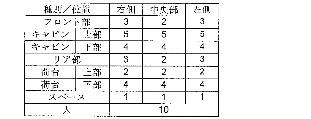
- Table 1 shows an example of the table used for the process P814 for setting the damage degree.
- the vehicle absorbs most of the kinetic energy at the time of a collision by deforming a part of the vehicle body. Generally, the vehicle body is vulnerable to impact and deforms more in the width direction than in the front-rear direction. Therefore, in Table 1, the degree of damage is set to be greater in the cabin than in the front and rear portions of the vehicle, which is the crushable zone.
- the deformation of the vehicle body is larger in an offset collision in which a part of the front surface of the vehicle collides than in a full flap collision in which the entire front surface of the vehicle collides. Therefore, in Table 1, the front portion and the rear portion are set so that the degree of damage is greater on both the left and right sides than the central portion in the width direction. Further, in Table 1, in order to prevent damage to humans, the damage degree of the target area OR including humans is set to be maximum, for example, twice or more the damage degree of the vehicle.
- the vehicle control device 100 sets the damage degree as follows. do.
- the vehicle control device 100 sets the damage degree of the target area OR including a person to "10" by the damage degree setting unit 122c according to Table 1.
- the overall damage level of the target area OR including a person is set to "10".
- the vehicle control device 100 has the following damage degree.
- the vehicle control device 100 sets the damage degree for each divided area SR of the target area OR including the sedan type vehicle shown in the upper central part of FIG. 7 according to Table 1 by the damage degree setting unit 122c.
- the damage degree setting unit 122c determines the damage degree of, for example, the rear upper divided areas SR112, SR122, SR132 set in the space S and the front upper divided areas SR312, SR322, SR332. , All set to "1".
- the damage degree setting unit 122c is, for example, in the target area OR including the sedan type vehicle, front: right side: lower part, front part: central part: lower part, front part: left side: lower part set in the front part.
- the damage levels of the divided areas SR311, SR321, and SR331 are set to "3", "2", and "3", respectively.
- the damage degree setting unit 122c is set in the cabin: central part: right side: upper part, central part: central part: upper part, central part: left side: upper part.
- the damage levels of the divided areas SR212, SR222, and SR232 are set to "5", respectively.
- the damage degree setting unit 122c has a central portion: right side: lower portion, a central portion: central portion: lower portion, and a central portion: left side: lower portion set in the cabin.
- the damage levels of the divided areas SR211, SR221, and SR231 are set to "4", respectively.
- the damage degree setting unit 122c is divided into a rear portion: right side: lower portion, a rear portion: central portion: lower portion, and a rear portion: left side: lower portion.
- the damage levels of SR111, SR121, and SR131 are set to "3", "2", and "3", respectively.
- the rear part of the target area OR right side: upper part, rear part: central part: upper part, rear part: Left side:
- Each upper division area SR112, SR122, SR132 is set in the cabin. Therefore, in the process P814, the vehicle control device 100 is, for example, by the damage degree setting unit 122c, of each of the divided regions SR112, SR122, SR132 in the upper part of the rear part of the target region OR including the minivan type vehicle shown in the upper right of FIG.
- the damage level is set to "5" according to Table 1.
- the vehicle control device 100 Set the damage level as follows. For example, the vehicle control device 100 is set in the cabin by setting the damage degree of all the divided areas SR above the target area OR set in the cabin to "5" by the damage degree setting unit 122c according to Table 1. The damage level of all the divided areas SR below the target area OR is set to "4".
- the vehicle control device 100 is next.
- Set the damage level as follows.
- the vehicle control device 100 sets the damage degree of all the divided areas SR in the upper part of the front part of the target area OR set in the cabin to "5" by the damage degree setting unit 122c according to Table 1.
- the damage degree setting unit 122c determines the damage degree of the divided areas SR212, SR222, SR232, SR112, SR122, SR132 in the upper part of the central part and the upper part of the rear part of the target area OR set on the loading platform according to Table 1. , Set to "2" respectively. Similarly, the damage degree setting unit 122c determines the damage degree of the divided areas SR211, SR221, SR231, SR111, SR121, SR131 in the lower part of the central part and the lower part of the rear part of the target area OR set on the loading platform according to Table 1. Set to "4" respectively.
- the own vehicle information storage unit 124 shown in FIG. 1 for example, similar to the target area OR shown in FIG. 5, information on a plurality of own vehicle division area VSRs obtained by dividing the own vehicle area VOR including the own vehicle V and information thereof. The degree of damage to the vehicle according to the magnitude of damage when an object set for each of the plurality of vehicle division areas VSR collides is recorded.
- the AD map generation unit 125 shown in FIG. 1 is output from, for example, map information including the position information of the own vehicle V, which is the output of the map unit V3, and road information around the own vehicle V, and the damage degree map generation unit 122.
- An automatic driving map of the own vehicle V is generated by fusing the three-dimensional object information of the object.
- the AD map generation unit 125 determines the planned travel route of the own vehicle V based on the information input from, for example, the own vehicle information storage unit 124, the damage degree map generation unit 122, the map unit V3, the vehicle sensor V4, and the like. It is generated and output to the travel control unit 123.
- the travel control unit 123 includes, for example, an automatic driving determination unit 123a and a vehicle control unit 123b.
- the automatic driving determination unit 123a for example, is based on the automatic driving map and the planned travel route input from the AD map generation unit 125 and various sensor information of the own vehicle V input from the vehicle sensor V4.
- the amount of control for the vehicle drive unit V5 required for automatic driving is calculated.
- the vehicle control unit 123b controls the vehicle drive unit V5, the display V6, the speaker V7, etc. based on the control amount for the vehicle drive unit V5 calculated by the automatic driving determination unit 123a, and automatically drives or operates the own vehicle V. Provide support.
- the vehicle control device 100 of the present embodiment is mounted on the own vehicle V, and is, for example, an outside world sensor V1, a communication unit V2, a map unit V3, a vehicle sensor V4, a vehicle drive unit V5, a display V6, and a speaker. It is connected to V7.
- the vehicle control device 100 controls the vehicle drive unit V5 by the travel control unit 123 to automatically drive or support the own vehicle V.
- FIG. 8 is an example of an automatic driving map generated by the AD map generation unit 125.
- the own vehicle V travels on a road with one lane on each side toward the intersection ahead, and the oncoming vehicle OV travels on the opposite lane of the road from the opposite direction toward the same intersection. Also, the oncoming vehicle OV is about to turn right at the intersection.
- the vehicle control device 100 mounted on the own vehicle V generates, for example, an automatic driving map as shown in FIG. 8 based on the map information around the own vehicle V output from the map unit V3.
- the vehicle control device 100 is, for example, by the AD map generation unit 125, from the own vehicle information storage unit 124, the three-dimensional object information of the own vehicle V, the own vehicle area VOR, a plurality of own vehicle division areas VSR, and each of the own vehicles.
- the damage level set in the vehicle division area VSR is read and reflected in the automatic driving map.
- the vehicle control device 100 generates three-dimensional object information by the three-dimensional object information generation unit 121 based on the information of the oncoming vehicle OV detected by the outside world sensor V1, for example.
- the vehicle control device 100 for example, by the damage degree map generation unit 122, has a plurality of target areas OR in the oncoming vehicle OV as shown in FIGS. 3 to 7 and Table 1.
- the division area SR is set, and the damage degree is set for each division area SR.
- the vehicle control device 100 is opposed by the automatic driving determination unit 123a based on, for example, the information of the oncoming vehicle OV input from the outside world sensor V1 and the sensor information input from the vehicle sensor V4. Estimate the travel route of the vehicle OV and the own vehicle V. Further, the automatic driving determination unit 123a determines, for example, the possibility of a collision between the own vehicle V and the oncoming vehicle OV based on the estimated travel route, and if there is a possibility of a collision, the vehicle drive unit V5. It is determined whether or not the collision between the own vehicle V and the oncoming vehicle OV can be avoided by the control of.
- the vehicle control device 100 controls the vehicle drive unit V5 by, for example, the vehicle control unit 123b. As a result, the throttle, brake, steering, etc. of the own vehicle V are automatically operated, and the collision between the own vehicle V and the oncoming vehicle OV is avoided.
- the vehicle control device 100 determines that the collision between the own vehicle V and the oncoming vehicle OV is unavoidable, for example, the automatic driving determination unit 123a determines that the own vehicle V and the oncoming vehicle OV after a predetermined time has elapsed. The position of is calculated, and the collision position CP is calculated.
- FIG. 9 is an example of the calculation result of the collision position CP and the collision damage degree between the own vehicle V and the oncoming vehicle OV by the automatic driving judgment unit 123a.
- the own vehicle V and the oncoming vehicle OV are both sedans type vehicles shown in the upper center portion of FIG. 7.
- the own vehicle V and the oncoming vehicle OV are the central portion of the own vehicle V: right side: lower portion and the central portion: right side: upper portion of the own vehicle division areas VSR211 and VSR212, and the front portion of the oncoming vehicle OV: right side: lower portion and Front part: Right side: Collision at the collision position CP with the upper division area SR311 and 312 is predicted.
- the own vehicle division areas VSR211 and VSR212 of the own vehicle V including the collision position CP are the upper right side of the cabin and the lower right side of the cabin, respectively, and as shown in Table 1, the degree of damage to the own vehicle is "5", respectively. "And” 4 "are set.
- the divided regions SR312 and 313 including the collision position CP of the oncoming vehicle OV are the space S and the right side of the front portion, respectively, and as shown in Table 1, the damage degrees are "1" and "3", respectively. Is set to. Therefore, the degree of collision damage between the own vehicle V and the oncoming vehicle OV shown in FIG. 9 is calculated by, for example, the automatic driving determination unit 123a as shown in the table of FIG.
- the collision damage degree between the own vehicle V and the oncoming vehicle OV is, for example, the product of the own vehicle damage degree set in the own vehicle division area VSR of the own vehicle V and the damage degree set in the own vehicle division area SR of the oncoming vehicle OV. It can be obtained as a corresponding value.
- the coefficient is set to "3"
- the division area SR of the own vehicle V and the oncoming vehicle OV is divided into an upper part and a lower part
- the degree of damage to the own vehicle V is divided into the upper part and the lower part, respectively.
- the product of the damage degree and the coefficient of the oncoming vehicle OV is calculated as the collision damage degree, and the total of them is used as the total collision damage degree.
- This coefficient is a numerical value set according to the relative speed and weight of the object colliding with the own vehicle V, and is not limited to "3".
- the vehicle control device 100 has, for example, the own vehicle damage degree and damage set in the own vehicle division region VSR of the own vehicle V and the own vehicle division region SR of the oncoming vehicle OV by the automatic driving determination unit 123a of the travel control unit 123.
- the running of the own vehicle V is controlled so as to minimize the collision damage degree corresponding to the degree.
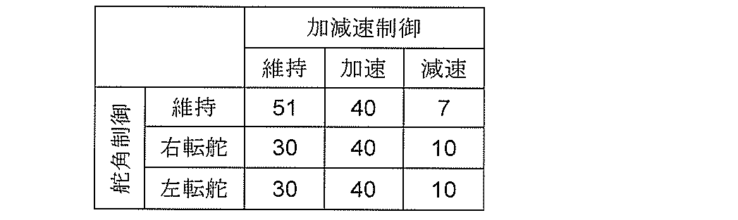
- the traveling control unit 123 for example, by the automatic driving determination unit 123a, can realize steering angle control and acceleration / deceleration control between the current time and the predicted collision time, as shown in Table 2 below.
- the degree of collision damage for each combination of is calculated.
- the traveling control unit 123 uses, for example, the automatic driving determination unit 123a to control three types of steering angle, that is, steering angle maintenance, right steering, and left steering, and vehicle speed maintenance, acceleration, and deceleration.
- the degree of collision damage for each combination with the three types of acceleration / deceleration control is calculated.
- the collision damage degree is the minimum "7".
- the collision position CP shown in FIG. 9 is, for example, at the front portion of the own vehicle V, the front portion: the central portion: the lower portion of the own vehicle division region VSR321, and the front portion of the oncoming vehicle OV.
- the travel control unit 123 controls the vehicle drive unit V5 by, for example, the vehicle control unit 123b, and executes the above-mentioned vehicle control that minimizes the collision damage degree.
- the front portion of the own vehicle V and the front portion of the oncoming vehicle OV are made to collide with each other to absorb the impact in both crushable zones, so that the collision damage can be minimized.
- the vehicle control device 100 of the present embodiment is a control device mounted on the vehicle V, and includes a three-dimensional object information generation unit 121, a damage degree map generation unit 122, and a travel control unit 123. ing.
- the three-dimensional object information generation unit 121 detects an object around the vehicle V and generates three-dimensional object information based on the outside world information output from the outside world sensor V1 mounted on the vehicle V.
- the damage degree map generation unit 122 generates information on a plurality of division areas SR in which the target area OR including an object is divided in the front-rear direction and the height direction, respectively, based on the generated outside world information, and also generates information on the plurality of division areas SR. For each SR, the degree of damage is set according to the magnitude of damage when the vehicle V collides. Then, the travel control unit 123 controls the travel of the vehicle V so as to minimize the collision damage degree corresponding to the damage degree set in the divided region SR.
- the vehicle control device 100 of the present embodiment detects an obstacle such as an oncoming vehicle OV by the outside world sensor V1, the obstacle is based on the outside world information output from the outside world sensor V1. It is possible to generate three-dimensional object information. Further, the vehicle control device 100 of the present embodiment divides the target region OR including the obstacle into the front-rear direction and the height direction of the obstacle, respectively, based on the generated three-dimensional object information. Information can be generated and the degree of damage can be set for each divided area SR. As a result, the risk can be estimated in more detail than the conventional vehicle control device according to the front-rear direction and the height direction of the obstacle, and the traveling control unit 123 avoids the collision with the obstacle or causes the collision damage. The running of the vehicle V can be controlled to minimize the degree.
- the vehicle control device 100 of the present embodiment further includes a conversion unit 122a and a feature extraction unit 122b.
- the conversion unit 122a faces the front and side surfaces of the object included in the three-dimensional object information based on the outside world information acquired from the diagonal direction intersecting the front and rear directions of the object by the outside world sensor V1, respectively. Convert to face-to-face information and face-to-face side information.
- the feature extraction unit 122b extracts the feature portion of the object from the facing side surface information.
- the damage degree map generation unit 122 divides the target area OR into a plurality of divided areas SR in the front-rear direction based on the extracted feature portion.
- the vehicle control device 100 of the present embodiment faces the front surface and the side surface of the object even when the outside world information of the object such as the oncoming vehicle OV is acquired from the oblique direction by the image pickup device V11 or the radar device V12. It is possible to obtain front-facing information and front-facing information. Further, the vehicle control device 100 of the present embodiment can more accurately extract the characteristic portion of the object based on the obtained front-facing information and front-facing side information. As a result, a plurality of divided region SRs according to the characteristics of the object can be generated more accurately, and the type and risk of obstacles can be estimated more accurately than the conventional vehicle control device.
- the outside world sensor V1 includes the image pickup device V11, and the outside world information includes the image information of the object captured by the image pickup device V11.
- the information on the front surface and the side surface of the object included in the three-dimensional object information is the image information of the front surface and the side surface of the object taken from an oblique direction, and the above-mentioned front surface information and the front surface information are the front surface information of the object, respectively. This is the face-to-face image information of the object and the face-to-face image information of the side surface of the object.
- the vehicle control device 100 of the present embodiment even when an image of an object such as an oncoming vehicle OV is taken from an oblique direction by the image pickup device V11, the facing image information RG1 facing the front surface and the side surface of the object, respectively. And the opposite image information RG2 can be obtained. Further, the vehicle control device 100 of the present embodiment can more accurately extract the characteristic portion of the object based on the obtained face-to-face image information RG1 and face-to-face image information RG2. As a result, a plurality of divided region SRs according to the characteristics of the object can be generated more accurately, and the type and risk of obstacles can be estimated more accurately than the conventional vehicle control device.
- the vehicle control device 100 of the present embodiment further includes an own vehicle information storage unit 124.
- the own vehicle information storage unit 124 the information of the plurality of own vehicle division region VSRs obtained by dividing the own vehicle region VOR including the vehicle V and the objects set for each of the plurality of own vehicle division region VSRs collide with each other. The degree of damage to the vehicle according to the magnitude of the damage at that time is recorded. Further, the travel control unit 123 controls the travel of the vehicle V so that the collision damage degree according to the product of the damage degree and the own vehicle damage degree is minimized.
- the vehicle control device 100 of the present embodiment is set in each of the own vehicle damage degree set in each of the plurality of own vehicle division regions VSR of the own vehicle V and each of the plurality of division region SRs of the target region OR. It becomes possible to estimate the degree of collision damage more accurately based on the degree of damage done. Therefore, by controlling the traveling of the vehicle V by the traveling control unit 123 so that the degree of collision damage is minimized, the risk of collision between the own vehicle V and the object can be further reduced.
- the feature extraction unit 122b recognizes a region in which no object exists from the facing side surface information and defines it as a space S, based on the space S and the plurality of divided regions SR.
- the divided region SR in which the object exists is set as a part of the vehicle V.
- the outside world sensor V1 includes, for example, a millimeter wave radar device as a radar device V12. Further, the damage degree map generation unit 122 recognizes the divided region SR including the windshield based on the reflection intensity of the radar output from the millimeter wave radar device, and the divided region SR including the windshield among the plurality of divided regions SR. Set the damage level corresponding to the cabin of the vehicle. With this configuration, it becomes possible to identify the cabin of a vehicle such as an oncoming vehicle OV based on the outside world information output from the millimeter wave radar device.
- the vehicle control device 100 of the present embodiment can be mounted not only on the sedan type own vehicle V but also on various types of vehicles as shown in FIG. 7, and collision damage of various types of vehicles can be achieved.
- the degree can be estimated more accurately than the conventional vehicle control device. Further, it is possible to accurately estimate not only the collision with the oncoming vehicle OV as shown in FIGS. 8 and 9, but also the degree of collision damage at the time of the rear-end collision of the own vehicle V.
- an example of calculating the degree of collision damage by the automatic driving determination unit 123a will be described with reference to FIGS. 10 to 13.
- FIG. 10 shows a case where the front part of the sedan type own vehicle V collides with the collision position CP at the rear part of the stopped sedan type preceding vehicle LV.
- the collision damage levels of the upper part of the preceding vehicle LV and the upper part and the lower part of the own vehicle V are "3" and "12", respectively, and the total collision damage degree is "15”.
- FIG. 11 shows a case where the front part of the sedan type own vehicle V collides with the collision position CP at the rear part of the stopped truck which is the preceding vehicle LV.
- the collision damage degree of the lower part of the preceding vehicle LV and the upper part and the lower part of the own vehicle V are "12" and "24", respectively, and the total collision damage degree is "36".
- FIG. 12 shows a case where the front part of the own vehicle V, which is a truck, collides with the collision position CP at the rear part of the stopped truck, which is the preceding vehicle LV.
- the collision damage degrees of the upper part and the lower part of the preceding vehicle LV and the own vehicle V are "30" and "48", respectively, and the overall collision damage degree is "78".
- FIG. 13 shows a case where the front part of the own vehicle V, which is a truck, collides with the collision position CP at the rear part of the stopped sedan type preceding vehicle LV.
- the degree of collision damage between the upper and lower parts of the preceding vehicle LV and the lower part of the own vehicle V is "12" and "24", respectively, and the total degree of collision damage is "36".
- the truck V is located behind the truck, which is the preceding vehicle LV, rather than when the truck V collides with the sedan-type preceding vehicle LV.
- the degree of collision damage is greater in the case of a rear-end collision. The reason is that the cabin of the truck is located in front of the vehicle body and the windshield is located at the upper part of the front part of the vehicle body. More specifically, when a following truck collides with a sedan-type preceding vehicle whose overall height is lower than that of the truck, the impact of the collision is less likely to reach the windshield of the following truck, so the degree of collision damage is relatively small. .. However, when the following truck collides with the preceding truck, the impact of the collision extends to the windshield of the following truck, so the degree of collision damage becomes relatively large.
- the type and risk of the obstacle are estimated more accurately than the conventional vehicle control device, and the collision between the obstacle and the vehicle V is more reliably avoided, or the collision damage is caused. It is possible to provide a vehicle control device 100 capable of reducing the problem.
- the damage degree map generation unit 122 acquires information on an object transmitted from the outside of the own vehicle V via the communication unit V2 mounted on the own vehicle V. It is different from the vehicle control device 100 of the first embodiment. Since the other points of the vehicle control device 100 of the present embodiment are the same as those of the vehicle control device 100 of the first embodiment, the same parts are designated by the same reference numerals and the description thereof will be omitted.
- FIG. 14 is a plan view illustrating the operation of the vehicle control device 100 of the present embodiment.
- the own vehicle V equipped with the vehicle control device 100 shown in FIG. 1 is traveling straight on a road with one lane on each side.
- Two parking vehicles PV1 and PV2 are parallel parked in the parking space attached to the road.
- These parked vehicles PV1 and PV2 have the same configuration as the own vehicle V shown in FIG. 1, and are equipped with the vehicle control device 100.
- the parked vehicles PV1 and PV2 detect objects around the parked vehicles PV1 and PV2 by the outside world sensor V1 even while parked.
- the outside world sensor V1 mounted on the leading parked vehicle PV1 parked on the front side in the traveling direction of the own vehicle V detects the pedestrian P who is about to cross the road.
- the pedestrian P is hidden behind the front parked vehicle PV1 and is located in the blind spot of the outside world sensor V1 of the parked vehicle PV2 parked behind the pedestrian P1 and the outside world sensor V1 of the own vehicle V.
- the vehicle control device 100 of the own vehicle V obtains information including three-dimensional object information, a speed, a moving direction, etc. of the pedestrian P transmitted from the communication unit V2 of the parked vehicle PV1 in front of the own vehicle V. Received via the communication unit V2.
- the vehicle control device 100 of the own vehicle V sets the target area OR and the damage degree of the pedestrian P based on the three-dimensional object information of the pedestrian P received via the communication unit V2, for example, by the damage degree map generation unit 122. do.
- the vehicle control device 100 of the own vehicle V is, for example, based on information such as the speed and the moving direction of the pedestrian P received via the communication unit V2, by the automatic driving determination unit 123a, the walking route of the pedestrian P. To estimate.
- the vehicle control device 100 estimates the traveling route of the own vehicle V by the automatic driving determination unit 123a based on the information input from the AD map generation unit 125 or the vehicle sensor V4, for example. Further, the automatic driving determination unit 123a determines, for example, the possibility of a collision between the own vehicle V and the pedestrian P based on the estimated travel route, and if there is a possibility of a collision, the vehicle drive unit V5. It is determined whether or not the collision between the own vehicle V and the oncoming vehicle OV can be avoided by the control of.
- FIG. 15 is an example of the calculation result of the collision position CP and the collision damage degree between the own vehicle V and the pedestrian P by the automatic driving determination unit 123a of the vehicle control device 100 of the own vehicle V.
- the vehicle control device 100 calculates the collision position CP based on, for example, the estimated walking path and moving speed of the pedestrian P and the traveling path and moving speed of the own vehicle V from the automatic driving determination unit 123a. Further, the vehicle control device 100 calculates the collision damage degree based on the calculated collision position CP, for example, by the damage degree map generation unit 122 as shown in the table of FIG.
- the own vehicle V is a sedan type vehicle
- the front portion: left side: lower portion and the front portion: left side: upper portion of the own vehicle division areas VSR331 and VSR332 are set in the front portion and the space S, respectively.
- the damage levels are set to "3" and "1", respectively.
- the overall damage level of the target area OR is set to, for example, "10”.
- the coefficient is set to, for example, "3”. Therefore, the collision damage degrees of the upper part and the lower part of the own vehicle V and the pedestrian P are "30" and "90", respectively, and are "120" as a whole.
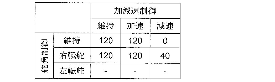
- the vehicle control device 100 controls the travel of the own vehicle V by the travel control unit 123 so as to minimize the collision damage degree corresponding to the damage degree of the own vehicle V and the pedestrian P shown in FIG. More specifically, the traveling control unit 123, for example, by the automatic driving determination unit 123a, can realize steering angle control and acceleration / deceleration control between the current time and the predicted collision time, as shown in Table 3 below. The degree of collision damage for each combination of is calculated.
- the traveling control unit 123 uses, for example, the automatic driving determination unit 123a to control three types of steering angle, steering angle maintenance, right steering, and left steering, and vehicle speed maintenance, acceleration, and deceleration.
- the degree of collision damage for each combination with the three types of acceleration / deceleration control is calculated.
- the travel control unit 123 controls the vehicle drive unit V5 by, for example, the vehicle control unit 123b, and executes the above-mentioned vehicle control that minimizes the collision damage degree.
- the own vehicle V can be decelerated in front of the pedestrian P to avoid a collision with the pedestrian P.
- the front and side image information G1 and G2 of the object included in the three-dimensional object information SI based on the image information of the object captured by the image pickup apparatus V11 are obtained on each surface.
- An example of converting to the facing image information RG1 and RG2 facing the above has been described.
- a laser radar may be used as the outside world sensor V1
- the three-dimensional information of the object output from the laser radar may be used as the outside world information.
- the conversion unit 122a faces the front and side surface information of the object included in the three-dimensional object information based on the external world information acquired from the diagonal direction intersecting the front and rear directions of the object, respectively. It can be converted into front-facing information and front-facing information.
- the object detected by the external sensor is described by taking a vehicle or a person as an example, but the object detected by the external sensor is, for example, a fence, a wall, a building, a signal, or a utility pole. , A guardrail, a median strip, or the like.
- the divided region including the windshield is identified based on the reflection intensity of the millimeter wave radar, but the divided region including the windshield may be identified based on the image of the image pickup apparatus.
- the functional blocks (software) realized by executing a program in which a part of the vehicle control device is loaded in the memory have been described, but a part or all of them may be described as, for example, an integrated circuit. It may be realized by hardware such as. Further, a part of the connection relationship shown in FIG. 1 may be omitted, and all the configurations may be connected to each other.
- the vehicle control device of the own vehicle receives the three-dimensional object information detected by the vehicle control device of another vehicle by vehicle-to-vehicle communication via each other's communication unit, the target area, the divided area, and the degree of damage are received. Etc. may be set by the vehicle control device of the own vehicle. Further, the target area, the divided area, the degree of damage, etc. set by the vehicle control device of another vehicle may be used by the vehicle control device of the own vehicle.
- Vehicle control device 121 Three-dimensional object information generation unit 122b Feature extraction unit 122 Damage degree map generation unit 123 Travel control unit 124 Own vehicle information storage unit G1 Image information G2 Image information OR Target area OV Oncoming vehicle (object) P Pedestrian (object) RG1 facing image information (front facing information) RG2 face-to-face image information (face-to-face side information) S Space SR Divided area V Own vehicle (vehicle) V1 External sensor V11 Image pickup device V12 Radar device (millimeter wave radar device) V2 communication unit VSR own vehicle division area
Landscapes
- Engineering & Computer Science (AREA)
- Physics & Mathematics (AREA)
- General Physics & Mathematics (AREA)
- Multimedia (AREA)
- Theoretical Computer Science (AREA)
- Automation & Control Theory (AREA)
- Transportation (AREA)
- Mechanical Engineering (AREA)
- Traffic Control Systems (AREA)
- Control Of Driving Devices And Active Controlling Of Vehicle (AREA)
Abstract
Description
図1は、本開示に係る車両制御装置の実施形態1を示すブロック図である。本実施形態の車両制御装置100は、たとえば、ガソリン車、ハイブリッド車、電気自動車などの車両Vに搭載され、車両Vの走行を制御する電子制御装置(ECU)である。車両制御装置100は、たとえば、車両Vを自律的に走行させる自動運転ECUであり、入出力インタフェース110と、メモリ120と、プロセッサ130と、不揮発性の補助記憶装置140とを備えている。
次に、本開示に係る車両制御装置の実施形態2を説明する。本実施形態の車両制御装置100は、被害度マップ生成部122が、自車両Vの外部から送信された物体の情報を、自車両Vに搭載された通信ユニットV2を介して取得する点で、実施形態1の車両制御装置100と異なっている。本実施形態の車両制御装置100のその他の点は、実施形態1の車両制御装置100と同様であるので、同様の部分には同様の符号を付して説明を省略する。
121 立体物情報生成部
122b 特徴抽出部
122 被害度マップ生成部
123 走行制御部
124 自車情報記憶部
G1 画像情報
G2 画像情報
OR 対象領域
OV 対向車(物体)
P 歩行者(物体)
RG1 正対画像情報(正対前面情報)
RG2 正対画像情報(正対側面情報)
S スペース
SR 分割領域
V 自車両(車両)
V1 外界センサ
V11 撮像装置
V12 レーダ装置(ミリ波レーダ装置)
V2 通信ユニット
VSR 自車分割領域
Claims (7)
- 車両に搭載される車両制御装置であって、
前記車両に搭載された外界センサから出力された外界情報に基づいて前記車両の周囲の物体を検知して立体物情報を生成する立体物情報生成部と、
前記外界情報に基づいて前記物体を含む対象領域を前後方向と高さ方向にそれぞれ分割した複数の分割領域の情報を生成するとともに前記複数の分割領域のそれぞれに対して前記車両が衝突したときの被害の大きさに応じた被害度を設定する被害度マップ生成部と、 前記被害度に対応する衝突被害度を最小にするように前記車両の走行を制御する走行制御部と、
を備えることを特徴とする車両制御装置。 - 前記外界センサによって前記物体の前後方向に交差する斜め方向から取得された前記外界情報に基づく前記立体物情報に含まれる前記物体の前面および側面の情報を該前面および該側面にそれぞれ正対する正対前面情報および正対側面情報に変換する変換部と、
前記正対側面情報から前記物体の特徴部分を抽出する特徴抽出部と、をさらに備え、
前記被害度マップ生成部は、前記特徴部分に基づいて前記対象領域を前記前後方向に前記複数の分割領域に分割することを特徴とする請求項1に記載の車両制御装置。 - 前記外界センサは、撮像装置を含み、
前記外界情報は、前記撮像装置によって撮影した前記物体の画像情報を含み、
前記前面および前記側面の情報は、前記斜め方向から撮影した前記物体の前記前面および前記側面の画像情報であり、
前記正対前面情報と前記正対側面情報は、それぞれ、前記前面の正対画像情報と前記側面の正対画像情報であることを特徴とする請求項2に記載の車両制御装置。 - 前記車両を含む自車領域を分割した複数の自車分割領域の情報と、該複数の自車分割領域のそれぞれに対して設定された前記物体が衝突したときの被害の大きさに応じた自車被害度と、が記録された自車情報記憶部をさらに備え、
前記走行制御部は、前記被害度と前記自車被害度の積に応じた衝突被害度が最小になるように前記車両の走行を制御することを特徴とする請求項1に記載の車両制御装置。 - 前記被害度マップ生成部は、前記車両の外部から送信された前記物体の前記対象領域と前記複数の分割領域と前記被害度とを、前記車両に搭載された通信ユニットを介して取得することを特徴とする請求項1に記載の車両制御装置。
- 前記特徴抽出部は、前記正対側面情報から前記物体が存在しない領域を認識してスペースとして規定し、前記スペースと前記複数の分割領域とに基づいて前記物体が存在する前記分割領域を前記車両の一部として設定することを特徴とする請求項2に記載の車両制御装置。
- 前記外界センサは、ミリ波レーダ装置を含み、
前記被害度マップ生成部は、前記ミリ波レーダ装置から出力されたレーダの反射強度に基づいてウィンドシールドを含む分割領域を認識し、前記複数の分割領域のうち前記ウィンドシールドを含む分割領域に車両のキャビンに対応する前記被害度を設定することを特徴とする請求項1に記載の車両制御装置。
Priority Applications (3)
| Application Number | Priority Date | Filing Date | Title |
|---|---|---|---|
| DE112021004404.4T DE112021004404T5 (de) | 2020-11-05 | 2021-09-27 | Fahrzeug-steuervorrichtung |
| US18/249,090 US12441305B2 (en) | 2020-11-05 | 2021-09-27 | Vehicle control device |
| JP2022560671A JP7399312B2 (ja) | 2020-11-05 | 2021-09-27 | 車両制御装置 |
Applications Claiming Priority (2)
| Application Number | Priority Date | Filing Date | Title |
|---|---|---|---|
| JP2020-185024 | 2020-11-05 | ||
| JP2020185024 | 2020-11-05 |
Publications (1)
| Publication Number | Publication Date |
|---|---|
| WO2022097387A1 true WO2022097387A1 (ja) | 2022-05-12 |
Family
ID=81457795
Family Applications (1)
| Application Number | Title | Priority Date | Filing Date |
|---|---|---|---|
| PCT/JP2021/035457 Ceased WO2022097387A1 (ja) | 2020-11-05 | 2021-09-27 | 車両制御装置 |
Country Status (4)
| Country | Link |
|---|---|
| US (1) | US12441305B2 (ja) |
| JP (1) | JP7399312B2 (ja) |
| DE (1) | DE112021004404T5 (ja) |
| WO (1) | WO2022097387A1 (ja) |
Families Citing this family (2)
| Publication number | Priority date | Publication date | Assignee | Title |
|---|---|---|---|---|
| US12485882B1 (en) * | 2021-10-29 | 2025-12-02 | Zoox, Inc. | Collision avoidance and mitigation in autonomous vehicles using predicted trajectories |
| JP7755237B2 (ja) * | 2022-11-04 | 2025-10-16 | トヨタ自動車株式会社 | 車両の制御装置、制御方法及び、プログラム |
Citations (6)
| Publication number | Priority date | Publication date | Assignee | Title |
|---|---|---|---|---|
| JP2008024108A (ja) * | 2006-07-19 | 2008-02-07 | Fuji Heavy Ind Ltd | 車両用衝突制御装置 |
| JP2009053059A (ja) * | 2007-08-27 | 2009-03-12 | Mitsubishi Electric Corp | 対象特定装置、対象特定方法および対象特定プログラム |
| JP2016002898A (ja) * | 2014-06-17 | 2016-01-12 | トヨタ自動車株式会社 | 車両用衝突制御装置 |
| WO2017056374A1 (ja) * | 2015-09-29 | 2017-04-06 | ソニー株式会社 | 被害低減装置、被害低減方法およびプログラム |
| WO2017111139A1 (ja) * | 2015-12-23 | 2017-06-29 | 京セラ株式会社 | サーバ装置、車両制御装置、および歩行補助装置 |
| JP2019026056A (ja) * | 2017-07-28 | 2019-02-21 | 株式会社Subaru | 車両の制御装置及び車両の制御方法 |
Family Cites Families (5)
| Publication number | Priority date | Publication date | Assignee | Title |
|---|---|---|---|---|
| US20040254729A1 (en) * | 2003-01-31 | 2004-12-16 | Browne Alan L. | Pre-collision assessment of potential collision severity for road vehicles |
| US7409295B2 (en) * | 2004-08-09 | 2008-08-05 | M/A-Com, Inc. | Imminent-collision detection system and process |
| DE112009004346B4 (de) * | 2009-01-29 | 2014-05-28 | Toyota Jidosha Kabushiki Kaisha | Objekterkennungsvorrichtung und Objekterkennungsverfahren |
| JP5684643B2 (ja) | 2011-05-06 | 2015-03-18 | 本田技研工業株式会社 | 車両制御装置、車両制御方法及びプログラム |
| KR101956685B1 (ko) * | 2018-05-14 | 2019-03-13 | 주식회사 만도 | 차량의 충돌 완화 장치 및 방법 |
-
2021
- 2021-09-27 US US18/249,090 patent/US12441305B2/en active Active
- 2021-09-27 DE DE112021004404.4T patent/DE112021004404T5/de active Pending
- 2021-09-27 WO PCT/JP2021/035457 patent/WO2022097387A1/ja not_active Ceased
- 2021-09-27 JP JP2022560671A patent/JP7399312B2/ja active Active
Patent Citations (6)
| Publication number | Priority date | Publication date | Assignee | Title |
|---|---|---|---|---|
| JP2008024108A (ja) * | 2006-07-19 | 2008-02-07 | Fuji Heavy Ind Ltd | 車両用衝突制御装置 |
| JP2009053059A (ja) * | 2007-08-27 | 2009-03-12 | Mitsubishi Electric Corp | 対象特定装置、対象特定方法および対象特定プログラム |
| JP2016002898A (ja) * | 2014-06-17 | 2016-01-12 | トヨタ自動車株式会社 | 車両用衝突制御装置 |
| WO2017056374A1 (ja) * | 2015-09-29 | 2017-04-06 | ソニー株式会社 | 被害低減装置、被害低減方法およびプログラム |
| WO2017111139A1 (ja) * | 2015-12-23 | 2017-06-29 | 京セラ株式会社 | サーバ装置、車両制御装置、および歩行補助装置 |
| JP2019026056A (ja) * | 2017-07-28 | 2019-02-21 | 株式会社Subaru | 車両の制御装置及び車両の制御方法 |
Also Published As
| Publication number | Publication date |
|---|---|
| JPWO2022097387A1 (ja) | 2022-05-12 |
| DE112021004404T5 (de) | 2023-07-20 |
| JP7399312B2 (ja) | 2023-12-15 |
| US12441305B2 (en) | 2025-10-14 |
| US20230391320A1 (en) | 2023-12-07 |
Similar Documents
| Publication | Publication Date | Title |
|---|---|---|
| US11809194B2 (en) | Target abnormality determination device | |
| JP6446732B2 (ja) | 車両制御装置、車両制御方法、および車両制御プログラム | |
| CN105774806B (zh) | 车辆行驶控制装置 | |
| JP6710710B2 (ja) | 車両制御装置、車両制御方法、およびプログラム | |
| WO2022133684A1 (zh) | 控制方法、相关设备及计算机可读存储介质 | |
| CN114258366A (zh) | 对于自主车辆的折线轮廓表示 | |
| CN114126940A (zh) | 电子控制装置 | |
| KR20210127267A (ko) | 차량 및 그 제어방법 | |
| JP2020185968A (ja) | 車両制御装置、車両制御方法、およびプログラム | |
| JP2019197467A (ja) | 車両制御装置 | |
| JP7163729B2 (ja) | 車両制御装置 | |
| JP7225185B2 (ja) | 車両制御装置、車両制御方法、およびプログラム | |
| JPWO2018131090A1 (ja) | 車両制御装置、車両制御方法、および車両制御プログラム | |
| JP2020147139A (ja) | 車両制御装置、車両制御方法、およびプログラム | |
| US20190064826A1 (en) | Autonomous driving device | |
| US20200168097A1 (en) | Vehicle control device, vehicle control method, and storage medium | |
| JP2019185112A (ja) | 車両制御装置、車両制御方法、およびプログラム | |
| JP2021068016A (ja) | 車両制御装置、車両制御方法、およびプログラム | |
| US12485888B2 (en) | Travel control apparatus for vehicle | |
| US12091046B2 (en) | Driving assistance apparatus | |
| JP7028838B2 (ja) | 周辺認識装置、周辺認識方法、およびプログラム | |
| JP7399312B2 (ja) | 車両制御装置 | |
| JP2021163142A (ja) | 車両制御装置、車両制御方法、およびプログラム | |
| JP2021160399A (ja) | 車両制御装置、車両制御方法、およびプログラム | |
| US11654914B2 (en) | Vehicle control device, vehicle control method, and storage medium |
Legal Events
| Date | Code | Title | Description |
|---|---|---|---|
| 121 | Ep: the epo has been informed by wipo that ep was designated in this application |
Ref document number: 21888940 Country of ref document: EP Kind code of ref document: A1 |
|
| ENP | Entry into the national phase |
Ref document number: 2022560671 Country of ref document: JP Kind code of ref document: A |
|
| 122 | Ep: pct application non-entry in european phase |
Ref document number: 21888940 Country of ref document: EP Kind code of ref document: A1 |
|
| WWG | Wipo information: grant in national office |
Ref document number: 18249090 Country of ref document: US |