WO2022092285A1 - Soldering device, soldering system, and processing device - Google Patents
Soldering device, soldering system, and processing device Download PDFInfo
- Publication number
- WO2022092285A1 WO2022092285A1 PCT/JP2021/040110 JP2021040110W WO2022092285A1 WO 2022092285 A1 WO2022092285 A1 WO 2022092285A1 JP 2021040110 W JP2021040110 W JP 2021040110W WO 2022092285 A1 WO2022092285 A1 WO 2022092285A1
- Authority
- WO
- WIPO (PCT)
- Prior art keywords
- control device
- image data
- unit
- robot
- solder
- Prior art date
Links
- 238000012545 processing Methods 0.000 title claims abstract description 459
- 238000005476 soldering Methods 0.000 title abstract description 133
- 229910000679 solder Inorganic materials 0.000 claims abstract description 719
- 238000006073 displacement reaction Methods 0.000 claims abstract description 141
- 239000003550 marker Substances 0.000 claims description 80
- 230000008859 change Effects 0.000 claims description 66
- 238000013459 approach Methods 0.000 claims description 55
- 230000001678 irradiating effect Effects 0.000 claims description 52
- 239000012636 effector Substances 0.000 claims description 43
- 238000009434 installation Methods 0.000 claims description 36
- 238000007689 inspection Methods 0.000 claims description 35
- 238000003384 imaging method Methods 0.000 claims description 23
- 238000001514 detection method Methods 0.000 abstract description 1014
- 239000000758 substrate Substances 0.000 abstract description 15
- 239000000155 melt Substances 0.000 abstract description 10
- 230000005855 radiation Effects 0.000 abstract 4
- 238000000034 method Methods 0.000 description 488
- 230000008569 process Effects 0.000 description 433
- 230000036544 posture Effects 0.000 description 410
- 238000003466 welding Methods 0.000 description 80
- 238000011960 computer-aided design Methods 0.000 description 77
- 230000003287 optical effect Effects 0.000 description 28
- 210000000707 wrist Anatomy 0.000 description 22
- 238000010586 diagram Methods 0.000 description 21
- 238000010801 machine learning Methods 0.000 description 15
- 208000036829 Device dislocation Diseases 0.000 description 14
- 230000002950 deficient Effects 0.000 description 14
- 239000000463 material Substances 0.000 description 13
- 238000003860 storage Methods 0.000 description 13
- 238000004364 calculation method Methods 0.000 description 12
- 238000007599 discharging Methods 0.000 description 12
- 238000002844 melting Methods 0.000 description 12
- 230000008018 melting Effects 0.000 description 12
- 230000004048 modification Effects 0.000 description 11
- 238000012986 modification Methods 0.000 description 11
- 238000010276 construction Methods 0.000 description 10
- 238000013461 design Methods 0.000 description 10
- 230000002123 temporal effect Effects 0.000 description 10
- 239000002184 metal Substances 0.000 description 8
- 238000012546 transfer Methods 0.000 description 7
- 239000011159 matrix material Substances 0.000 description 6
- 239000000779 smoke Substances 0.000 description 6
- 239000006096 absorbing agent Substances 0.000 description 5
- 230000009466 transformation Effects 0.000 description 5
- 239000011248 coating agent Substances 0.000 description 4
- 238000000576 coating method Methods 0.000 description 4
- 238000009826 distribution Methods 0.000 description 4
- 238000005219 brazing Methods 0.000 description 3
- 239000006071 cream Substances 0.000 description 3
- 230000000694 effects Effects 0.000 description 3
- 239000000284 extract Substances 0.000 description 3
- 238000000605 extraction Methods 0.000 description 3
- 238000004519 manufacturing process Methods 0.000 description 3
- 230000007246 mechanism Effects 0.000 description 3
- 230000010363 phase shift Effects 0.000 description 3
- 230000001133 acceleration Effects 0.000 description 2
- 239000000853 adhesive Substances 0.000 description 2
- 230000001070 adhesive effect Effects 0.000 description 2
- 239000003990 capacitor Substances 0.000 description 2
- 230000007423 decrease Effects 0.000 description 2
- 238000007667 floating Methods 0.000 description 2
- 230000004927 fusion Effects 0.000 description 2
- 230000005484 gravity Effects 0.000 description 2
- 238000010438 heat treatment Methods 0.000 description 2
- 238000005304 joining Methods 0.000 description 2
- 238000002366 time-of-flight method Methods 0.000 description 2
- 230000000007 visual effect Effects 0.000 description 2
- 230000003190 augmentative effect Effects 0.000 description 1
- 230000000295 complement effect Effects 0.000 description 1
- 230000007547 defect Effects 0.000 description 1
- 230000002542 deteriorative effect Effects 0.000 description 1
- 238000005516 engineering process Methods 0.000 description 1
- 239000000945 filler Substances 0.000 description 1
- 230000006870 function Effects 0.000 description 1
- 230000006872 improvement Effects 0.000 description 1
- 238000011900 installation process Methods 0.000 description 1
- 238000003754 machining Methods 0.000 description 1
- 230000013011 mating Effects 0.000 description 1
- 238000004021 metal welding Methods 0.000 description 1
- 239000012778 molding material Substances 0.000 description 1
- 238000002360 preparation method Methods 0.000 description 1
- 238000004886 process control Methods 0.000 description 1
- 238000003672 processing method Methods 0.000 description 1
- 230000002250 progressing effect Effects 0.000 description 1
- 230000009467 reduction Effects 0.000 description 1
- 239000011347 resin Substances 0.000 description 1
- 229920005989 resin Polymers 0.000 description 1
Images


Classifications
-
- B—PERFORMING OPERATIONS; TRANSPORTING
- B23—MACHINE TOOLS; METAL-WORKING NOT OTHERWISE PROVIDED FOR
- B23K—SOLDERING OR UNSOLDERING; WELDING; CLADDING OR PLATING BY SOLDERING OR WELDING; CUTTING BY APPLYING HEAT LOCALLY, e.g. FLAME CUTTING; WORKING BY LASER BEAM
- B23K1/00—Soldering, e.g. brazing, or unsoldering
- B23K1/005—Soldering by means of radiant energy
- B23K1/0056—Soldering by means of radiant energy soldering by means of beams, e.g. lasers, E.B.
-
- B—PERFORMING OPERATIONS; TRANSPORTING
- B25—HAND TOOLS; PORTABLE POWER-DRIVEN TOOLS; MANIPULATORS
- B25J—MANIPULATORS; CHAMBERS PROVIDED WITH MANIPULATION DEVICES
- B25J13/00—Controls for manipulators
- B25J13/08—Controls for manipulators by means of sensing devices, e.g. viewing or touching devices
-
- B—PERFORMING OPERATIONS; TRANSPORTING
- B23—MACHINE TOOLS; METAL-WORKING NOT OTHERWISE PROVIDED FOR
- B23K—SOLDERING OR UNSOLDERING; WELDING; CLADDING OR PLATING BY SOLDERING OR WELDING; CUTTING BY APPLYING HEAT LOCALLY, e.g. FLAME CUTTING; WORKING BY LASER BEAM
- B23K1/00—Soldering, e.g. brazing, or unsoldering
- B23K1/0008—Soldering, e.g. brazing, or unsoldering specially adapted for particular articles or work
- B23K1/0016—Brazing of electronic components
-
- B—PERFORMING OPERATIONS; TRANSPORTING
- B23—MACHINE TOOLS; METAL-WORKING NOT OTHERWISE PROVIDED FOR
- B23K—SOLDERING OR UNSOLDERING; WELDING; CLADDING OR PLATING BY SOLDERING OR WELDING; CUTTING BY APPLYING HEAT LOCALLY, e.g. FLAME CUTTING; WORKING BY LASER BEAM
- B23K1/00—Soldering, e.g. brazing, or unsoldering
- B23K1/005—Soldering by means of radiant energy
-
- B—PERFORMING OPERATIONS; TRANSPORTING
- B23—MACHINE TOOLS; METAL-WORKING NOT OTHERWISE PROVIDED FOR
- B23K—SOLDERING OR UNSOLDERING; WELDING; CLADDING OR PLATING BY SOLDERING OR WELDING; CUTTING BY APPLYING HEAT LOCALLY, e.g. FLAME CUTTING; WORKING BY LASER BEAM
- B23K26/00—Working by laser beam, e.g. welding, cutting or boring
- B23K26/02—Positioning or observing the workpiece, e.g. with respect to the point of impact; Aligning, aiming or focusing the laser beam
- B23K26/03—Observing, e.g. monitoring, the workpiece
- B23K26/032—Observing, e.g. monitoring, the workpiece using optical means
-
- B—PERFORMING OPERATIONS; TRANSPORTING
- B23—MACHINE TOOLS; METAL-WORKING NOT OTHERWISE PROVIDED FOR
- B23K—SOLDERING OR UNSOLDERING; WELDING; CLADDING OR PLATING BY SOLDERING OR WELDING; CUTTING BY APPLYING HEAT LOCALLY, e.g. FLAME CUTTING; WORKING BY LASER BEAM
- B23K26/00—Working by laser beam, e.g. welding, cutting or boring
- B23K26/08—Devices involving relative movement between laser beam and workpiece
- B23K26/082—Scanning systems, i.e. devices involving movement of the laser beam relative to the laser head
-
- B—PERFORMING OPERATIONS; TRANSPORTING
- B23—MACHINE TOOLS; METAL-WORKING NOT OTHERWISE PROVIDED FOR
- B23K—SOLDERING OR UNSOLDERING; WELDING; CLADDING OR PLATING BY SOLDERING OR WELDING; CUTTING BY APPLYING HEAT LOCALLY, e.g. FLAME CUTTING; WORKING BY LASER BEAM
- B23K26/00—Working by laser beam, e.g. welding, cutting or boring
- B23K26/08—Devices involving relative movement between laser beam and workpiece
- B23K26/0869—Devices involving movement of the laser head in at least one axial direction
- B23K26/0876—Devices involving movement of the laser head in at least one axial direction in at least two axial directions
- B23K26/0884—Devices involving movement of the laser head in at least one axial direction in at least two axial directions in at least in three axial directions, e.g. manipulators, robots
-
- B—PERFORMING OPERATIONS; TRANSPORTING
- B25—HAND TOOLS; PORTABLE POWER-DRIVEN TOOLS; MANIPULATORS
- B25J—MANIPULATORS; CHAMBERS PROVIDED WITH MANIPULATION DEVICES
- B25J11/00—Manipulators not otherwise provided for
- B25J11/005—Manipulators for mechanical processing tasks
-
- B—PERFORMING OPERATIONS; TRANSPORTING
- B25—HAND TOOLS; PORTABLE POWER-DRIVEN TOOLS; MANIPULATORS
- B25J—MANIPULATORS; CHAMBERS PROVIDED WITH MANIPULATION DEVICES
- B25J13/00—Controls for manipulators
- B25J13/08—Controls for manipulators by means of sensing devices, e.g. viewing or touching devices
- B25J13/088—Controls for manipulators by means of sensing devices, e.g. viewing or touching devices with position, velocity or acceleration sensors
-
- B—PERFORMING OPERATIONS; TRANSPORTING
- B25—HAND TOOLS; PORTABLE POWER-DRIVEN TOOLS; MANIPULATORS
- B25J—MANIPULATORS; CHAMBERS PROVIDED WITH MANIPULATION DEVICES
- B25J19/00—Accessories fitted to manipulators, e.g. for monitoring, for viewing; Safety devices combined with or specially adapted for use in connection with manipulators
- B25J19/02—Sensing devices
- B25J19/021—Optical sensing devices
- B25J19/023—Optical sensing devices including video camera means
-
- B—PERFORMING OPERATIONS; TRANSPORTING
- B25—HAND TOOLS; PORTABLE POWER-DRIVEN TOOLS; MANIPULATORS
- B25J—MANIPULATORS; CHAMBERS PROVIDED WITH MANIPULATION DEVICES
- B25J9/00—Programme-controlled manipulators
- B25J9/16—Programme controls
- B25J9/1694—Programme controls characterised by use of sensors other than normal servo-feedback from position, speed or acceleration sensors, perception control, multi-sensor controlled systems, sensor fusion
- B25J9/1697—Vision controlled systems
-
- B—PERFORMING OPERATIONS; TRANSPORTING
- B23—MACHINE TOOLS; METAL-WORKING NOT OTHERWISE PROVIDED FOR
- B23K—SOLDERING OR UNSOLDERING; WELDING; CLADDING OR PLATING BY SOLDERING OR WELDING; CUTTING BY APPLYING HEAT LOCALLY, e.g. FLAME CUTTING; WORKING BY LASER BEAM
- B23K2101/00—Articles made by soldering, welding or cutting
- B23K2101/36—Electric or electronic devices
- B23K2101/42—Printed circuits
-
- G—PHYSICS
- G05—CONTROLLING; REGULATING
- G05B—CONTROL OR REGULATING SYSTEMS IN GENERAL; FUNCTIONAL ELEMENTS OF SUCH SYSTEMS; MONITORING OR TESTING ARRANGEMENTS FOR SUCH SYSTEMS OR ELEMENTS
- G05B2219/00—Program-control systems
- G05B2219/30—Nc systems
- G05B2219/37—Measurements
- G05B2219/37555—Camera detects orientation, position workpiece, points of workpiece
-
- G—PHYSICS
- G05—CONTROLLING; REGULATING
- G05B—CONTROL OR REGULATING SYSTEMS IN GENERAL; FUNCTIONAL ELEMENTS OF SUCH SYSTEMS; MONITORING OR TESTING ARRANGEMENTS FOR SUCH SYSTEMS OR ELEMENTS
- G05B2219/00—Program-control systems
- G05B2219/30—Nc systems
- G05B2219/40—Robotics, robotics mapping to robotics vision
- G05B2219/40584—Camera, non-contact sensor mounted on wrist, indep from gripper
-
- G—PHYSICS
- G05—CONTROLLING; REGULATING
- G05B—CONTROL OR REGULATING SYSTEMS IN GENERAL; FUNCTIONAL ELEMENTS OF SUCH SYSTEMS; MONITORING OR TESTING ARRANGEMENTS FOR SUCH SYSTEMS OR ELEMENTS
- G05B2219/00—Program-control systems
- G05B2219/30—Nc systems
- G05B2219/45—Nc applications
- G05B2219/45104—Lasrobot, welding robot
-
- G—PHYSICS
- G05—CONTROLLING; REGULATING
- G05B—CONTROL OR REGULATING SYSTEMS IN GENERAL; FUNCTIONAL ELEMENTS OF SUCH SYSTEMS; MONITORING OR TESTING ARRANGEMENTS FOR SUCH SYSTEMS OR ELEMENTS
- G05B2219/00—Program-control systems
- G05B2219/30—Nc systems
- G05B2219/45—Nc applications
- G05B2219/45235—Dispensing adhesive, solder paste, for pcb
Definitions
- the present invention relates to a technical field of a soldering apparatus and a soldering system that irradiates a processing light to perform soldering, and a processing apparatus that irradiates a processing light to process an object.
- Patent Document 1 As this type of device, for example, a device that projects a laser beam from a laser head attached to a robot arm toward a portion to be soldered has been proposed (see Patent Document 1).
- Patent Document 2 is mentioned as another related technique.
- a technical problem with this type of device is, for example, proper soldering to a substrate having a three-dimensional shape (that is, a 3D substrate).
- a soldering device that irradiates processing light for melting solder arranged on a circuit board, has a galvano mirror, and irradiates the processing light through the galvano mirror.
- the device a detection device that detects light from the circuit board and generates at least one of image data and shape data, and the light irradiation device and the detection device are provided, and the light irradiation device and the above are provided.
- the processing light from the light irradiation device that is displaced together with the detection device is the same as that of the robot arm having a drive unit that moves the detection device and the light irradiation device that is displaced together with the detection device based on at least one of the data that changes with the displacement of the detection device.
- a soldering device comprising a control device for controlling the orientation of the galvano mirror so that the position is illuminated.
- a processing device that irradiates an object with processing light, has a scanning unit, and irradiates the processing light through the scanning unit, and a light irradiation device from the object.
- the moving device Based on the detection device provided with the detection device for detecting light, the light irradiation device and the detection device, the moving device having a drive unit for moving the light irradiation device and the detection device, and the detection result of the detection device.
- a processing device including a control device for controlling the scanning unit is provided.
- the third aspect it is a soldering system for soldering an element to a circuit board, the first moving device provided with a solder discharging device for discharging solder and having a drive unit for moving the solder discharging device.
- a second moving device having a holding device capable of holding the element and having a driving unit for moving the holding device, a light irradiating device for irradiating processing light for melting the solder, and light from the circuit board are detected.
- a third moving device having a driving unit for moving the light irradiation device and the detecting device, and (i) the solder discharging device so that solder is arranged in a predetermined portion of the circuit board.
- the holding device is controlled so that the element is arranged on the circuit board via the arranged solder, and (iii) the circuit is based on the detection result of the detection device.
- a soldering system including a control device that controls the drive unit of the third moving device so as to bring the light irradiation device closer to a substrate, and controls the light irradiation device so as to melt the arranged solder. Provided.
- soldering system that solders an element to a circuit board, and irradiates a solder ejection device that ejects solder, a holding device that can hold the element, and processing light that melts the solder.
- a moving device having a light irradiating device, a detecting device for detecting light from the circuit board, a solder discharging device, a holding device, a light irradiating device, and a driving unit for moving the detecting device, (i).
- the drive unit is controlled so that the solder discharge device, the holding device, the light irradiation device, and the detection device approach the circuit board, and (ii) the solder is arranged in a predetermined portion of the circuit board.
- solder ejection device is controlled, the holding device is controlled so that the element is arranged on the circuit board via the solder arranged (iii), and the solder arranged is melted.
- a soldering system comprising a control device for controlling a light irradiation device is provided.
- a processing device that irradiates an object with processing light, that is, a light irradiation device that irradiates the processing light, a detection device that detects light from the object, and the light irradiation device.
- the detection device and includes a moving device having a drive unit for moving the light irradiation device and the detection device, and a control device for controlling the drive unit based on the detection result of the detection device. Processing equipment is provided.
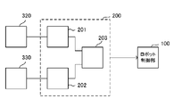
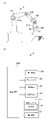
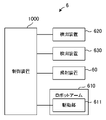
- FIG. 1 is a diagram schematically showing the overall structure of the soldering system according to the first embodiment.
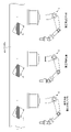
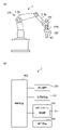
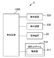
- FIG. 2 is a system configuration diagram showing a configuration of a robot constituting a part of the soldering system according to the first embodiment.
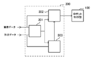
- FIG. 3 is a system configuration diagram showing a configuration of a robot constituting another part of the soldering system according to the first embodiment.
- FIG. 4 is a system configuration diagram showing a configuration of a robot constituting another part of the soldering system according to the first embodiment.
- FIG. 5 is a diagram schematically showing the configuration of one detection device according to the first embodiment.
- FIG. 6 is a diagram schematically showing the configuration of another detection device according to the first embodiment.
- FIG. 1 is a diagram schematically showing the overall structure of the soldering system according to the first embodiment.
- FIG. 2 is a system configuration diagram showing a configuration of a robot constituting a part of the soldering system according to the first embodiment.
- FIG. 3 is a system configuration diagram showing
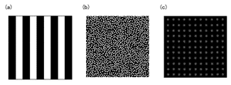
- FIG. 7 is a diagram showing an example of structural light projected by a projector included in another detection device according to the first embodiment.
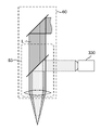
- FIG. 8 is a diagram showing a part of an optical path included in the light irradiation device according to the first embodiment.
- FIG. 9 is a diagram schematically showing a configuration of a matching processing unit included in the control device according to the first embodiment.
- FIG. 10 is a diagram for explaining the concept of the matching process according to the first embodiment.
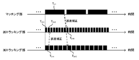
- FIG. 11 is a diagram showing an example of a timing chart of the matching process according to the first embodiment.
- FIG. 12 is a diagram schematically showing a configuration of a tracking unit included in the control device according to the first embodiment.
- FIG. 13 is a diagram showing an example of a timing chart of the tracking process according to the first embodiment.
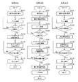
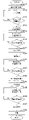
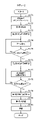
- FIG. 14 is a flowchart showing the operation of the soldering system according to the first embodiment.
- FIG. 15 is a diagram showing an example of an irradiation method of processing light.
- FIG. 16 is a diagram schematically showing an air blower and a smoke absorber.
- FIG. 17 is a system configuration diagram showing the configuration of the soldering system according to the second embodiment.
- FIG. 18 is a flowchart showing the operation of the soldering system according to the second embodiment.
- FIG. 19 is a diagram showing a part of an optical path included in the light irradiation device according to the modified example.
- FIG. 20 is a diagram schematically showing the configuration of the tracking unit according to the modified example.
- FIG. 21 is a diagram schematically showing the overall configuration of the laser welding system according to the third embodiment.
- FIG. 22 is a system configuration diagram showing a configuration of a robot constituting a part of the laser welding system according to the third embodiment.
- FIG. 23 is a system configuration diagram showing a configuration of a robot constituting another part of the laser welding system according to the third embodiment.
- FIG. 24 is a flowchart showing the operation of the laser welding system according to the third embodiment.
- FIG. 25 is a flowchart showing the operation of the application example of the robot according to the first embodiment.
- the soldering system is a soldering system in which an element is soldered to a circuit board T.
- the soldering system includes a robot 1, a robot 2, and a robot 3.
- the robot 1 which may be referred to as a processing device or a solder coating device, is provided with a dispenser 40 (see FIGS. 2 (a) and 2 (b)), which may be referred to as a solder discharge device, for discharging solder. It has a robot arm 110, which may be referred to as a first moving means, having a driving unit 111 (see FIG. 2B) for moving the dispenser 40.
- the robot 2 which may be referred to as a processing device or an element installation device, is provided with a holding device 50 (see FIGS. 3A and 3B) capable of holding an element and which may be referred to as a gripping device.
- a robot arm 210 which may be referred to as a second moving means, has a driving unit 211 (see FIG. 3B) for moving the holding device 50.
- the robot 3 which may be referred to as a processing device or a soldering device, is a light irradiation device 60 (see FIGS. 4A and 4B) that irradiates processing light for melting solder, and a circuit board T.
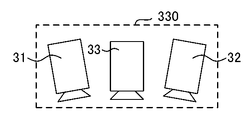
- Detection devices 320 and 330 (see FIGS. 4 (a) and 4 (b)) for detecting light are provided, and a drive unit 311 (FIG. 4 (b)) for moving the light irradiation device 60 and the detection devices 320 and 330 is provided.
- the robot arm 310 which may be referred to as a third moving means, is provided.
- the "circuit board” may be a circuit board (that is, a 3D circuit board) having a three-dimensional shape composed of a circuit film on which a circuit is formed and a board. That is, the circuit board may be a circuit board manufactured by the IMPC (registered trademark) (In-Mold Printed Circuit) manufacturing method. Further, the circuit board is not limited to the circuit board manufactured by the IMPC manufacturing method, and may be, for example, a circuit board having a three-dimensional shape composed of a circuit film and a substrate manufactured by another manufacturing method. Further, the circuit board is not limited to a circuit board composed of a circuit film and a substrate, and may be a circuit board having another three-dimensional shape.
- IMPC registered trademark
- the circuit board is not limited to the circuit board manufactured by the IMPC manufacturing method, and may be, for example, a circuit board having a three-dimensional shape composed of a circuit film and a substrate manufactured by another manufacturing method. Further, the circuit board is not limited to a circuit board composed of
- the circuit board is not limited to a circuit board having a three-dimensional shape (3D circuit board), and may be a circuit board having a planar shape composed of a circuit film on which a circuit is formed and a board. Further, the circuit board may not be a circuit board having a three-dimensional shape (3D circuit board), and may be a circuit board in which the circuit is formed on the board itself. Further, the circuit board may be a circuit board for surface mounting or a circuit board for through-hole mounting.
- a marker that can be used for attitude control, position control, and the like of at least one end effector of robots 1, 2 and 3 that is, a dispenser 40, a holding device 50, a light irradiation device 60
- a detection device described later for example, a two-dimensional code such as an AR (Augmented Reality) marker, a cross mark, etc.), a solder pad (land), or the like may be included.
- the above markers, solder pads, and the like can be detected by a detection device described later for posture control and position control of at least one end effector of the robots 1, 2 and 3, and a detection device described later (for example, an image). Can be recognized by).
- the “element” is an element that is soldered to the circuit board T by the soldering system, and examples thereof include an electronic element and an electric element. Further, the element may be a surface mount element or an insert mount element (that is, a lead element). Such an “element” may be paraphrased as a "part”.
- the element includes an LED (Light Emitting Diode) (for example, a well-known element such as a chip LED), a resistor (for example, a well-known element such as a chip resistor), a capacitor (for example, a well-known element such as a chip capacitor), and a transistor. (For example, a well-known element such as a chip transistor), a connector, or the like.
- robot arm is used, it is not limited to robot arms (that is, vertical articulated robots), but various existing robots such as SCARA robots (that is, horizontal articulated robots), parallel link robots, and orthogonal robots. Aspects are applicable. Further, as long as the light irradiation device 60 or the like can be moved, an existing moving mechanism may be applied instead of the robot arm 312 or the like.
- the robot arms 110, 210 and 310 may be industrial robots or collaborative robots.
- the soldering system controls the dispenser 40 as an end effector of the robot 1 so that the solder is (i) arranged in a predetermined portion of the circuit board T, and (ii) is placed on the circuit board T via the arranged solder.
- the holding device 50 as an end effector of the robot 2 is controlled so that the element is arranged, and (iii) the end effector of the robot 3 is placed on the circuit board T based on the detection results of at least one of the detection devices 320 and 330.
- the control device 1000 (FIGS. 2B and 3) controls the drive unit 311 of the robot arm 310 so as to bring the light irradiation device 60 closer to the solder, and controls the light irradiation device 60 so as to melt the arranged solder. b) and FIG. 4 (b)).
- the control device 1000 first controls the dispenser 40 of the robot 1 so that the solder is arranged (in other words, the solder is applied) at a predetermined portion of the circuit board T conveyed by the belt conveyor. (Solder placement process). Next, the control device 1000 controls the holding device 50 of the robot 2 so that the element is arranged via the arranged solder on the circuit board T'where the solder is arranged (element installation step). The control device 1000 then sets the drive unit 311 of the robot arm 310 so that the light irradiation device 60 is brought closer to the circuit board T ′′ on which the element is installed, based on the detection results of at least one of the detection devices 320 and 330.
- the light irradiation device 60 is controlled so as to be controlled and melt the arranged solder (soldering step). After that, the control device 1000 may inspect the soldered solder and the element from the detection result of the detection device 330, for example (inspection step).
- the soldering of the element to the circuit board T can be made more efficient, and the throughput of the soldering of the element can be improved. Can be done.
- circuit board T the circuit board on which the solder is arranged
- circuit board T' the circuit board on which the element is installed
- circuit board T' the circuit board on which the element is installed
- the solder may be, for example, cream solder (that is, solder paste), thread solder, bar solder, or the like. That is, the dispenser 40 may arrange, for example, cream solder, thread solder, bar solder, or the like on the circuit board T.
- "to melt the arranged solder” includes irradiating a predetermined portion of the circuit board T with processing light to melt the solder.
- this predetermined portion includes solder placed on the solder pad of the circuit board T.
- the processing light from the light irradiation device 60 is directly applied to the solder to melt the solder.
- the predetermined portion is a part of the solder pad provided on the circuit board T (for example, a part of the solder pad on which the solder is not arranged) or a part of the element arranged on the circuit board T (for example, the element). Electrodes) are included.
- the circuit board T may be a flat substrate or a 3D circuit board having a three-dimensional shape as described above.
- the predetermined portion may be set on an inclined surface on the circuit board T.
- the dispenser 40 of the robot 1 may dispose the solder on at least a part of a predetermined portion (for example, a solder pad) of the inclined surface.
- the light irradiation device 60 of the robot 3 is applied to a predetermined portion (for example, a portion of the solder pad where the solder is not arranged) so as to melt the solder arranged in the predetermined portion of the inclined surface as the predetermined portion. It may be irradiated with processing light.
- the robot 3 is a robot that irradiates the processing light that melts the solder arranged on the circuit board T.
- the robot 3 has (i) a galvano mirror 61 (see FIG. 8), and detects light from the light irradiation device 60 that irradiates the processing light through the galvano mirror 61 and (ii) the circuit board T.
- the detection devices 320 and 330 that generate at least one of the image data and the shape data, and (iii) the light irradiation device 60 and the detection devices 320 and 330 are provided, and the light irradiation device 60 and the detection devices 320 and 330 are provided.
- a robot arm 310 having a drive unit 311 for moving the light beam is provided.
- the robot arm 310 has arm portions 310a and 310b and a wrist portion 310c.
- the drive unit 311 rotates, for example, a motor that swivels the entire robot arm 310, a motor that moves the entire robot arm 310 back and forth, a motor that moves each of the arm portions 310a and 310b up and down, and the arm portion 310b and the wrist portion 310c. It may have a motor, a motor that rotates the wrist portion 310c, and a motor that bends the wrist portion 310c (neither is shown).
- the robot arm 310 may have a linear motion joint in addition to the rotary joint.
- the drive unit 311 rotates the entire robot arm 310 and moves it back and forth, and at least one of the arms 310a and 310b is moved up and down to move the wrist portion 310c to a position near the circuit board T, for example. Move it.
- the drive unit 311 further rotates the arm portion 310b and the wrist portion 310c, and rotates or bends the wrist portion 310c to melt the solder arranged on the circuit board T, for example.
- 60 can irradiate at least a part of a predetermined portion (for example, solder arranged on the circuit board T, a solder pad provided on the circuit board T, an element arranged on the circuit board T, etc.). Or change the posture of the light irradiation device 60.
- the drive unit 311 operates the robot arm 310, for example, as described above, the detection devices 320 and 330 and the light irradiation device 60 are moved toward, for example, the circuit board T.
- the robot arm 310 and the detection device 320 are calibrated by an existing method.
- an object whose exact shape is known for example, a checker board
- the detection device 320 is placed at an accurate position in the three-dimensional coordinate system (so-called world coordinate system) of the robot arm 310, and the object is imaged by the detection device 320.
- the correspondence between the coordinate system of the detection device 320 (so-called camera coordinate system) and the coordinate system of the robot arm is obtained (that is, calibration is performed).
- the robot arm 310 and the detection device 330 are also calibrated by the existing method.
- the detection device 320 is arranged on the arm portion 310b of the robot arm 310, and the detection device 330 is arranged on the wrist portion 310c of the robot arm 310, but the detection device 320 and The arrangement of 330 is not limited to this.
- both the detection device 320 and the detection device 330 may be arranged on the wrist portion 310c, the arm portion 310b, or the robot arm 310 with the wrist portion 310c and the arm portion 310b. May be located at different positions.
- the robot 3 may be provided with only one of the detection devices 320 and 330, or may be provided with another detection device in addition to the detection devices 320 and 330 (that is, the robot 3 has 3 or more).
- the robot 3 may be provided with at least one detection device other than the detection devices 320 and 330. That is, the solder arranged on the circuit board T is provided on the circuit board T or a predetermined portion of the circuit board T (for example, on the circuit board T) by driving the drive unit 311 of the robot arm 310 so that the solder can be melted by the processing light. If the light irradiation device 60 can be brought close to the solder pad, the element arranged on the circuit board T, the solder, etc.), the configurations of the detection devices 320 and 330 (for example, the number and specifications of cameras in the detection device, the presence or absence of a projector, etc.) And the placement position and number may be any.
- the detection device 320 is configured to include cameras 21 and 22 which may be referred to as an image pickup device.
- the cameras 21 and 22 each have an optical member such as a lens and an image pickup device such as a CMOS (Complementary Metal-Oxide-Semicondutor) or a CCD (Challge Coupled Device).
- CMOS Complementary Metal-Oxide-Semicondutor
- CCD Challge Coupled Device
- the cameras 21 and 22 may be configured as stereo cameras arranged so as to be spaced apart from each other by a predetermined baseline length.
- the cameras 21 and 22 are configured to be able to detect the light incident on them by the image sensor.
- the incident light include light reflected by an object (for example, at least a part of a circuit board T), light scattered by the object, light transmitted through the object, and the like.
- the cameras 21 and 22 detect the light from the object existing in each angle of view and capture the image of the object. That is, each of the cameras 21 and 22 is configured to be able to detect the light incident on itself and generate image data (that is, data indicating a two-dimensional image) as the detection result.
- the cameras 21 and 22 are configured to be able to output image data indicating the captured image.
- each of the cameras 21 and 22 is configured to be able to detect an object.
- the "image data" is, for example, data in which each pixel of each image sensor of the cameras 21 and 22 is associated (in other words, associated) with a pixel value of each pixel, for example, a luminance value. be.
- the detection device 320 takes an image of an object (for example, at least a part of the circuit board T) by the cameras 21 and 22 at the same time, and as a detection result based on the two image data output from the cameras 21 and 22 respectively.
- Shape data (that is, shape data indicating the three-dimensional shape of an object) is generated and configured to be output.
- the detection device 320 is configured to be able to output the generated shape data as shape data used for, for example, matching processing and tracking processing described later.
- the shape data is three-dimensional point cloud data (hereinafter, also simply referred to as point cloud data).
- the detection device 320 determines the difference (that is, the difference) between the position of the object on the image captured by the camera 21 and the position of the object on the image captured by the camera 22 and the cameras 21 and 22. Based on the focal length and the distance between the camera 21 and the camera 22 (that is, the baseline length), the distance from the cameras 21 and 22 to the object is calculated by a well-known method to generate point group data.
- the point cloud data is data in which the points corresponding to the pixels of the cameras 21 and 22 are associated with the three-dimensional information (X coordinate, Y coordinate, Z coordinate).
- the shape data is not limited to the point cloud data, and may be data representing existing three-dimensional information such as depth image data in which the distance to the object is associated with the brightness value of each pixel.
- the detection device 320 does not have to image the object with the camera 21 and the camera 22 and generate shape data based on the two image data output from each of the cameras 21 and 22.
- the detection device 320 may be configured to be able to output two image data output from the cameras 21 and 22, respectively, as the detection result.
- the two image data output from each of the cameras 21 and 22 may be input to the control device 1000.
- the control device 1000 may generate shape data based on the two input image data by a well-known method as described above.
- the control device 1000 may perform the matching process and the tracking process described later based on the generated shape data.
- the detection device 320 is configured to be able to output image data generated by at least one of the cameras 21 and 22 as image data used for, for example, matching processing and tracking processing described later.
- the detection device 320 obtains at least a part of the circuit board T from a wide range in order to approach the circuit board T. It is configured to be detectable. In other words, it is configured so that at least a part of the circuit board T or its surroundings can be imaged and at least one of a wide range of image data and shape data can be generated. Therefore, for the cameras 21 and 22, cameras having a wider field of view than the cameras 31 and 32 of the detection device 330, which will be described later, are used. For example, as the cameras 21 and 22, cameras having a larger angle of view (in other words, a shorter focal length) than the cameras 31 and 32 described later are used. That is, for example, as the cameras 21 and 22, lenses having a larger angle of view (in other words, having a shorter focal length) than the lenses of the cameras 31 and 32 described later are used.
- the detection device 320 is not limited to the case where the circuit board T as an object and, for example, the light irradiation device 60 are relatively separated from each other, and the circuit board T as an object and the light irradiation device 60, for example, are compared. It is also possible to detect at least a part of the circuit board T from a wide range when the target is approached.
- the detection device 320 generates, for example, at least one of image data and shape data of at least a part of the circuit board T as an object.
- at least a part (that is, an object) of the circuit board T is, for example, at least a part of the circuit board T itself or a marker formed on the circuit board T (for example, a two-dimensional code such as an AR marker or a cross). Marks) and solder pads (lands) formed on the circuit board T.
- the detection device 120 is, for example, at least the image data and shape data of a marker (for example, a two-dimensional code such as an AR marker or a cross mark) arranged on the circuit board T or an element provided on the circuit board T. One may be generated. Further, the detection device 120 may generate at least one of the image data and the shape data of the marker (for example, a two-dimensional code such as an AR marker or a cross mark) arranged in the vicinity of the circuit board T, for example.
- the detection device 320 may be composed of a single camera instead of the cameras 21 and 22. In this case, a single camera produces image data of the object. Further, the detection device 320 may include yet another camera in addition to the cameras 21 and 22. In this case, for example, the cameras 21 and 22 (stereo cameras) may generate shape data, and another camera may generate image data. Further, the detection device 320 may include a projector in addition to the cameras 21 and 22 as in the detection device 330 described later. In this case, the detection device 320 may be configured to generate and output at least one of the image data and the shape data of the object.
- the detection device 320 captures an object on which structural light is projected from the projector by the cameras 21 and 22 (stereo camera), and outputs the images from the cameras 21 and 22, respectively, as in the detection device 330 described later. It is not necessary to generate shape data based on the two image data.
- the detection device 320 can output two image data (two image data of the object on which the structural light is projected) output from the cameras 21 and 22 (stereo camera), respectively, as the detection result. It may be configured.
- the two image data output from the cameras 21 and 22, respectively, may be input to the control device 1000.
- the control device 1000 may generate shape data based on the two input image data by a well-known method.
- the control device 1000 may perform the matching process and the tracking process described later based on the generated shape data.
- the detection device 320 may include a single camera and a projector instead of the cameras 21 and 22. In this case, the detection device 320 may be configured to generate and output at least one of the image data and the shape data of the object.
- the detection device 320 captures an object on which structural light is projected from the projector with a single camera, and a single camera, similar to the detection device 330 described later. It is not necessary to generate shape data based on the image data output from.
- the detection device 320 may be configured to be able to output image data output from a single camera as a detection result.
- the image data output from a single camera may be input to the control device 1000.
- the control device 1000 may also generate shape data based on the input image data from a single camera by a well-known method.
- the control device 1000 may perform the matching process and the tracking process described later based on the generated shape data.
- the detection device 320 includes a projector
- the detection device 130 includes cameras 31 and 32, which may be referred to as an image pickup device, and a projector 33, which may be referred to as a projection device.
- the cameras 31 and 32 each include an optical member such as a lens and an image pickup element such as a CMOC or a CCD.
- the cameras 31 and 32 may be configured as stereo cameras arranged so as to be spaced apart from each other by a predetermined baseline length. The cameras 31 and 32 are configured to be able to detect the light incident on them.
- the incident light examples include light reflected by an object (for example, at least a part of a circuit board T), light scattered by the object, light transmitted through the object, and the like.
- the cameras 31 and 32 detect the light from the object existing in each angle of view and capture the image of the object.
- the cameras 31 and 32 detect the light from the object existing in each angle of view and capture the image of the object. That is, each of the cameras 31 and 32 is configured to be able to detect the light incident on itself and generate image data (that is, data indicating a two-dimensional image) as the detection result.
- the cameras 31 and 32 are configured to be able to generate image data indicating the captured image.
- the detection device 330 is configured to be capable of outputting image data generated by at least one of the cameras 31 and 32 as image data used for, for example, matching processing and tracking processing described later.
- the projector 33 is configured to be able to project structural light having a predetermined intensity distribution (in other words, a predetermined pattern) as shown in FIGS. 7A to 7C, for example, when the detection device 330 is operated. It should be noted that various existing modes such as a DLP (Digital Light Processing) type projector can be applied to the projector 33.
- a DLP Digital Light Processing
- the detection device 330 is configured to be able to project structural light from the projector 33 onto the object and generate image data of the object on which the structural light is projected by the cameras 31 and 32. By projecting a predetermined pattern of structural light by the projector 33, the detection device 330 is less affected by disturbance even when the surface of the object is dark or the surface of the object has few feature points. Highly accurate shape data can be generated.
- the detection device 330 captures an object on which structural light is projected from the projector 33 by the cameras 31 and 32 at the same time, and shape data (that is, a three-dimensional shape of the object) based on the two image data output respectively. (Shape data indicating) is generated and configured to be output.
- shape data that is, a three-dimensional shape of the object
- shape data indicating is generated and configured to be output.
- the difference between the position of the pattern due to the structural light on the image captured by the camera 31 and the position of the pattern due to the structural light on the image captured by the camera 32 that is, the parallax.
- the distance from the cameras 31 and 32 to the object is calculated by a well-known method and is three-dimensional.
- Generates point group data (hereinafter, also simply referred to as point group data).
- the detection device 330 is configured to be able to output the generated shape data as shape data used for, for example, matching processing and tracking processing described later.
- the detection device 330 captures an object on which structural light is projected from the projector 33 by the cameras 31 and 32 (stereo camera), and obtains shape data based on the two image data output from the cameras 31 and 32, respectively. It does not have to be generated.
- the detection device 330 is configured to be able to output two image data (two image data of the object on which the structural light is projected) output from the cameras 31 and 32, respectively, as the detection result. May be good.
- the two image data output from the cameras 31 and 32, respectively, may be input to the control device 1000.
- the control device 1000 may generate shape data based on the two input image data by a well-known method as described above.
- the control device 1000 may perform the matching process and the tracking process described later based on the generated shape data.
- the shape data is not limited to point cloud data, and may be data representing existing three-dimensional information such as depth image data in which the distance to the object is associated with the brightness value of each pixel.
- various existing modes such as a phase shift method, a random dot method, and a TOF (Time-of-Flight) method can be applied.
- the detection device 330 is configured to be able to generate image data by at least one of the cameras 31 and 32 in a state where the structural light is not projected from the projector 33.
- the detection device 330 is attached to a part of the circuit board T (for example, solder arranged on the circuit board T or the circuit board T). It is configured so that at least a part of the circuit board T can be detected with high accuracy in order to get closer to the provided solder pad, the element arranged on the circuit board T, etc.)). In other words, it is configured so that at least a part of the circuit board T or its surroundings can be imaged and at least one of high-precision image data and shape data can be generated. Therefore, the cameras 31 and 32 have a higher resolution than the cameras 21 and 22 included in the detection device 320.
- the cameras 31 and 32 have a narrower angle of view (in other words, a longer focal length) than the cameras 21 and 22.
- the lenses of the cameras 31 and 32 each have a narrower angle of view (in other words, a longer focal length) than the lenses of the cameras 21 and 22 respectively.
- the lenses of the cameras 31 and 32 may have higher shooting magnifications than the lenses of the cameras 21 and 22 respectively.
- the detection device 330 can detect at least a part of the circuit board T with higher accuracy than the detection device 320. Therefore, by using the image data and the shape data generated by the detection device 330 in the control device 1000, the estimation accuracy of the position and orientation by the matching process in the matching processing unit 200 described later and the position and orientation by the tracking process in the tracking unit 300 are used. The estimation accuracy of is high.
- the detection device 330 is not limited to the case where the circuit board T as an object and, for example, the light irradiation device 60 are relatively close to each other, and the circuit board T as an object and, for example, the light irradiation device 60 are relatively close to each other. When they are separated, at least a part of the circuit board T can be detected with high accuracy. That is, even when the circuit board T as an object and, for example, the light irradiation device 60 are relatively separated, at least a part of the circuit board T may be detected.
- the detection device 320 may be referred to as a first image pickup unit, and the detection device 330 may be referred to as a second image pickup unit.
- the detection device 330 generates, for example, at least one of image data and shape data of at least a part of the circuit board T as an object.
- at least a part (that is, an object) of the circuit board T is, for example, at least a part of the circuit board T itself or a marker formed on the circuit board T (for example, a two-dimensional code such as an AR marker or a cross). Mark) and solder pad (land).
- the detection device 330 is, for example, image data and shape data of a marker (for example, a two-dimensional code such as an AR marker or a cross mark) arranged on the circuit board T, an element or solder provided on the circuit board T. You may generate at least one of them.
- the detection device 330 may generate at least one of image data and shape data of a marker (for example, a two-dimensional code such as an AR marker or a cross mark) arranged in the vicinity of the circuit board T, for example.
- the detection device 330 may be composed of a single camera instead of the cameras 31 and 32. In this case, a single camera produces image data of the object. Further, the detection device 330 may include yet another camera in addition to the cameras 31 and 32. In this case, for example, the cameras 31 and 32 (stereo cameras) and the projector 33 may generate shape data, and another camera may generate image data. Further, the detection device 330 may include a single camera and a projector 33 instead of the cameras 31 and 32. In this case, the detection device 330 may be configured to generate and output at least one of the image data and the shape data of the object.
- the detection device 330 captures an object on which structural light is projected from the projector by a single camera, and is based on image data output from the single camera. It is not necessary to generate shape data.
- the detection device 320 may be configured to be able to output image data output from a single camera as a detection result.
- the image data output from a single camera may be input to the control device 1000.
- the control device 1000 may generate shape data based on input image data from a single camera by a well-known method.
- the control device 1000 may perform the matching process and the tracking process described later based on the generated shape data.
- the detection device 330 does not have to include the projector 33.
- the detection device 330 may be configured to generate and output at least one of the image data and the shape data, similarly to the detection device 320.
- the detection device 330 does not have to image the object with the camera 31 and the camera 32 (stereo camera) and generate shape data based on the two image data output from each of the cameras 31 and 32.
- the detection device 330 may be configured to be able to output two image data output from the cameras 31 and 32, respectively, as the detection result.
- the two image data output from each of the cameras 31 and 32 may be input to the control device 1000.
- the control device 1000 may generate shape data based on the two input image data by a well-known method as described above.
- the control device 1000 may perform the matching process and the tracking process described later based on the generated shape data.
- the field of view of the cameras 21 and 22 of the detection device 320 may be the same as the field of view of the cameras 31 and 32 of the detection device 330, and the field of view of the detection device 330 may be larger than the field of view of the cameras 21 and 22 of the detection device 320.
- the fields of view of the cameras 31 and 32 may be large.
- the resolution of the cameras 21 and 22 of the detection device 320 may be the same as the resolution of the cameras 31 and 32 of the detection device 330, and the resolution of the detection device 330 may be higher than the resolution of the cameras 21 and 22 of the detection device 320.
- the resolutions of the cameras 31 and 32 may be low.
- the light irradiation device 60 includes a galvano mirror 61, which can be rephrased as a scanning unit, and an f ⁇ lens 62. Therefore, the light irradiation device 60 moves the irradiation position of the processed light L on the object (for example, at least a part of the circuit board T) along a desired direction (in other words, the processed light L on the object). It is possible to scan the irradiation position of.
- the galvano mirror 61 is configured so that the direction of its own mirror can be changed, and by changing the direction of its own mirror, the emission direction of the processed light L incident from the light source (not shown) is changed.
- the processed light L emitted from the galvano mirror 61 is incident on the f ⁇ lens 62.
- the f ⁇ lens 62 collects the processed light L incident from the galvano mirror 61. That is, the light irradiation device 60 is a circuit as an object via the f ⁇ lens 62 according to the direction of its own mirror in the galvano mirror 61 (in other words, the change in the emission direction of the processed light L from the galvano mirror 61).
- the irradiation position of the processing light L irradiated on the substrate T can be changed.
- the galvano mirror 61 includes a first scanning mirror 61Y and a second scanning mirror 61X having a mirror that swings or rotates about a predetermined axis, and swinging the first scanning mirror 61Y and the second scanning mirror 61X.
- the rotating axes are arranged so as to intersect (for example, orthogonally) with each other.
- the processed light L incident on the first scanning mirror 61Y is reflected by the first scanning mirror 61Y and incident on the second scanning mirror 61X, and is reflected by the second scanning mirror 61X and incident on the f ⁇ lens 62.
- the f ⁇ lens 62 collects the processed light L incident from the second scanning mirror 61X.
- the emission direction of the processed light L from the second scanning mirror 61X differs depending on the orientation around the axis of the first scanning mirror 61Y and the orientation around the axis of the second scanning mirror 61X (in other words, the f ⁇ lens 62 of the processed light L). Because the incident position is different), the irradiation position of the processing light on the circuit board T changes depending on the orientation of the first scanning mirror 61Y and the second scanning mirror 61X.
- the light irradiation device 60 can melt the solder by irradiating the solder arranged on the circuit board T with the processing light L.
- the solder is not limited to directly irradiating the solder with the processing light L, and for example, the solder pad provided on the circuit board T (for example, the portion of the solder pad on which the solder is not arranged) is irradiated with the processing light. It is also possible to indirectly melt the solder by irradiating a part (for example, an electrode) of an element (component) arranged on the circuit board T with processing light.
- the galvano mirror 61 is not limited to having two scanning mirrors (first scanning mirror 61Y and second scanning mirror 61X), but may be a single scanning mirror or is composed of three or more scanning mirrors. May be.
- the light irradiation device 60 is not limited to the galvano mirror 61, and other existing devices that change the light emission direction, such as a polygon mirror, a DMD (Digital Micromirror Device), and a spatial light modulator, may be applied.
- the light irradiation device 60 is not limited to the configuration including the f ⁇ lens 62, and may not have the f ⁇ lens 62, or may include another one or more lenses instead of the f ⁇ lens 62.
- the light source (not shown) of the processed light L incident on the galvano mirror 61 of the light irradiation device 60 may be arranged outside the soldering system or may be included in the soldering system. However, it may be included in the robot 3 or may be included in the light irradiation device 60.
- the light source (not shown) can change the intensity of the processed light L applied to the object.
- the method of changing the intensity of the processed light L applied to the object is not limited to the method of changing the intensity of the light emitted from the light source, but the method of using an existing light intensity changing member such as an ND filter is applied. You can also do it.
- the light from the light source (not shown) is incident on the galvano mirror 61 of the light irradiation device 60 by an existing method.
- the light irradiation device 60 may include a focus lens.
- the focus lens is composed of one or more lenses, and by changing the position of at least a part of the lenses along the optical axis direction, the condensing position of the processed light L in the optical axis direction of the light irradiation device 60 (that is, that is). , The focal position of the light irradiation device 60) can be changed.
- the spot size of the processed light L applied to the object can be changed.
- the focus lens may be arranged on the optical path of the processed light L before it is incident on the galvano mirror 61.
- the configuration for changing the spot size of the processed light L in the object is not limited to the focus lens, and the existing configuration can also be applied.
- the control device 1000 has the detection device 320 and the detection device 1000 based on the data of at least one of the image data and the shape data, which changes with the displacement of at least one of the detection devices 320 and 330 for the robot 3 configured as described above.
- the orientation of the galvano mirror 61 may be controlled so that the processed light L from the light irradiation device 60, which is displaced with the displacement of at least one of the 330, is irradiated to the same position.
- the control device 1000 may control the drive unit 311 so as to stop the drive of the drive unit 311.
- the control device 1000 is based on at least one of the image data and the shape data that changes with the displacement of at least one of the detection devices 320 and 330 after the drive of the drive unit 311 is stopped, and the detection devices 320 and 330.
- the orientation of the galvano mirror 61 may be controlled so that the processed light L from the light irradiating device 60 that is displaced together with at least one of the above is irradiated at the same position.
- the control device 1000 controls the drive unit 311 so that the light irradiation device 60 and the detection devices 320 and 330 are moved, and is accompanied by the displacement of at least one of the detection devices 320 and 330 moved by the robot arm 310. Based on at least one of the changing image data and the shape data, the orientation of the galvano mirror 61 is controlled so that the processed light L from the light irradiation device 60 moved by the robot arm 310 is irradiated to the same position. You may.
- the control device 1000 is irradiated with light that is displaced with the displacement of at least one of the detection devices 320 and 330 based on at least one of the image data and the shape data that changes with the displacement of at least one of the detection devices 320 and 330.
- the orientation of the galvano mirror 61 may be controlled so as to be maintained at a second position different from the first position.
- the control device 1000 may control the drive unit 311 so as to stop the drive of the drive unit 311.
- the control device 1000 is based on at least one of the image data and the shape data that changes with the displacement of at least one of the detection devices 320 and 330 after the drive of the drive unit 311 is stopped, and the detection devices 320 and 330.
- the galvano mirror 61 is maintained at a second position different from the first position. The orientation may be controlled.
- the control device 1000 controls the drive unit 311 so as to move the light irradiation device 60 and the detection devices 320 and 330, and changes with the displacement of at least one of the detection devices 320 and 330 moved by the robot arm 310.
- the irradiation position of the processed light L from the light irradiation device 60 moved by the robot arm 310 is maintained at the first position based on at least one of the image data and the shape data to be generated, the first position and the irradiation position are maintained. May control the orientation of the galvano mirror 61 so that it is maintained in a different second position.
- the control device 1000 controls the drive unit 311 of the robot arm 310 so that the light irradiation device 60 and the detection devices 320 and 330 come close to the circuit board T based on at least one of the image data and the shape data.
- the detection device 320 and the detection device 320 and the detection device 320 and 330 are based on the above-mentioned at least one data that changes with the displacement of at least one of the detection devices 320 and 330.
- the orientation of the galvano mirror 61 may be controlled so that the processed light L from the light irradiating device 60, which is displaced together with at least one of the 330, is irradiated at the same position.
- the light irradiation device 60 does not have to include a scanning unit such as a galvano mirror 61.
- the control device 1000 may be a device different from the robot 3 which can be paraphrased as a soldering device, or may form a part of the robot 3 (in other words, the robot 3 is a control device). It may be equipped with 1000). In the latter case, the control device 1000 may be provided independently by the robot 3 or may be shared by the robot 3 and at least one of the robots 1 and 2 (that is, constitutes a part of the robot 3). The control device 1000 may control at least one of the robots 2 and 3 in addition to the robot 3). When the robot 3 independently includes the control device 1000, the robots 1 and 2 may independently include a control device 1000 different from the control device 1000 included in the robot 3, respectively.
- the robot 1 is a robot that arranges solder on a predetermined portion (for example, a solder pad, a part of a circuit, etc.) of the circuit board T.
- the robot 1 detects light from (i) a dispenser 40 for discharging solder and (ii) a circuit board T, and at least one of image data and shape data.
- the robot arm 110 has arm portions 110a and 110b and a wrist portion 110c, similarly to the robot arm 310.
- the detection devices 120 and 130 may be configured in the same manner as the detection devices 320 and 330, respectively.
- the dispenser 40 can change the amount of cream solder discharged, and the control device 1000 can control the amount of solder discharged from the dispenser 40.
- the detection device 120 is arranged on the arm portion 110b of the robot arm 110, and the detection device 130 is arranged on the wrist portion 110c of the robot arm 110.
- the arrangement of 130 is not limited to this.
- the robot 1 may be provided with only one of the detection devices 120 and 130, or may be provided with another detection device in addition to the detection devices 120 and 130 (that is, the robot 1 may have three or more). May be equipped with a detection device).
- the predetermined portion of the circuit board T or the circuit board T (for example, the predetermined portion of the circuit board T or the circuit board T is driven by the drive unit 111 of the robot arm 110 so that the solder can be arranged on the predetermined portion of the circuit board T (for example, a solder pad or a part of the circuit).
- the dispenser 40 can be brought close to a solder pad, a part of a circuit, etc.
- the configuration for example, the number and specifications of cameras in the detection device, the presence or absence of a projector, etc.
- the arrangement position, and the number of the detection devices 120 and 130 can be determined. Either may be used.
- the detection devices 120 and 130 may have the same configuration as the detection devices 320 and 330 described above, respectively. However, the detection devices 120 and 130 do not have to have the same configuration as the detection devices 320 and 330 described above, respectively.
- the configuration and specifications of the detection device 120 can be appropriately changed as long as it does not contradict the gist or idea that can be read from the above-mentioned explanation of the detection device 320 and the like.
- the configuration and specifications of the detection device 130 can be appropriately changed as long as it does not contradict the gist or idea that can be read from the description of the detection device 330 described above.
- the control device 1000 determines the detection device 120 and the robot 1 configured as described above based on at least one of the image data and the shape data, which changes with the displacement of at least one of the detection devices 120 and 130.
- the drive unit 111 may be controlled so that the solder discharged from the dispenser 40, which is displaced with the displacement of at least one of the 130, is arranged in a predetermined portion of the circuit board T.
- the control device 1000 may control the drive unit 111 so as to stop the drive of the drive unit 111.
- the control device 1000 is based on at least one of the image data and the shape data that changes with the displacement of at least one of the detection devices 120 and 130 after the drive of the drive unit 111 is stopped, and the detection devices 120 and 130.
- the drive unit 111 may be controlled so that the solder discharged from the dispenser 40, which is displaced together with at least one of the above, is arranged in a predetermined portion of the circuit board T.
- the control device 1000 displaces with the displacement of at least one of the detection devices 120 and 130 based on at least one of the image data and the shape data that changes with the displacement of at least one of the detection devices 120 and 130.
- the drive unit 111 may be controlled so as to be arranged at a second position different from the first position.
- the control device 1000 may control the drive unit 111 so as to stop the drive of the drive unit 111.
- the control device 1000 is based on at least one of the image data and the shape data that changes with the displacement of at least one of the detection devices 120 and 130 after the drive of the drive unit 111 is stopped, and the detection devices 120 and 130.
- the drive unit 111 is controlled so that the solder discharged from the dispenser 40, which is displaced with the displacement of at least one of the above, is arranged at the first position of the circuit board T and then is arranged at the second position different from the first position. You may.
- the control device 1000 controls the drive unit 111 of the robot arm 110 so that the dispenser 40 and the detection devices 120 and 130 come close to the circuit board T based on at least one of the image data and the shape data, and the dispenser 40 controls the drive unit 111. And at least one of the detectors 120 and 130 based on the at least one data that changes with the displacement of at least one of the detectors 120 and 130 when the detectors 120 and 130 approach the circuit board T to a predetermined distance.
- the drive unit 111 may be controlled so that the solder discharged from the dispenser 40, which is displaced together with the solder, is arranged in a predetermined portion of the circuit board T.
- control device 1000 may be a device different from the robot 1 which can be paraphrased as a solder coating device, or may form a part of the robot 1 (in other words, the robot 1 is a control device). It may be equipped with 1000).
- the robot 2 is a robot that arranges elements via solder arranged on the circuit board T.
- the robot 2 detects light from the holding device 50 holding the element (i) and the circuit board T (ii), and at least the image data and the shape data.
- a robot arm provided with detection devices 220 and 230 for generating one of the data, (iii) holding devices 50 and detection devices 220 and 230, and having a drive unit 211 for moving the holding devices 50 and the detection devices 220 and 230. It is equipped with 210.
- the robot arm 210 has arm portions 210a and 210b and a wrist portion 210c, similarly to the robot arm 310.
- the detection devices 220 and 230 may be configured in the same manner as the detection devices 220 and 230, respectively.
- an existing device such as a tweezers hand or a suction device can be applied as long as the element can be held.
- the holding force (grip force) of the element in the holding device 50 can be changed, and the control device 1000 can control the holding force of the element in the holding device 50.
- the holding device 50 can control the force of pinching the element with the tip of the tweezers.
- the robot 2 may include a storage unit (not shown) for accommodating elements and a supply device (not shown) for supplying a desired element from the storage unit to the holding device 50. Examples of the storage unit include reels, trays, sticks, and the like. Since various existing modes can be applied to the storage unit and the supply device, the details thereof will be omitted.
- the control device 1000 controls the supply device so as to supply the desired element to be arranged on a part (predetermined part) of the circuit board T from the accommodating portion to the holding device 50, and the holding device 50 holds the element.
- the holding device 50 may be controlled.
- the robot 2 brings the holding device 50 closer to an element supply device (so-called parts feeder) (so-called parts feeder) (so-called parts feeder) (so-called parts feeder) (so-called parts feeder) (so-called parts feeder) in which an element to be arranged in a part (predetermined part) of the circuit board T is separately provided to obtain a desired element. Since the work of holding by the holding device 50 can be omitted, the work of arranging the elements on the circuit board T can be made more efficient.
- the detection device 220 is arranged on the arm portion 210b of the robot arm 210, and the detection device 230 is arranged on the wrist portion 210c of the robot arm 210, but the detection device 220 and The arrangement of 230 is not limited to this. Further, the robot 2 may be provided with only one of the detection devices 220 and 230, or may be provided with another detection device in addition to the detection devices 220 and 230 (that is, the robot 2 may have three or more). May be equipped with a detection device).
- the predetermined portion of the circuit board T (solder pad or If the holding device 50 can be brought close to the solder placed on the circuit, the configuration of the detection devices 120 and 130 (for example, the number and specifications of cameras in the detection device, the presence or absence of a projector, etc.), the placement position, and the number will be determined. But it may be.
- the detection devices 220 and 230 may have the same configuration as the detection devices 320 and 330 described above, respectively. However, the detection devices 220 and 230 do not have to have the same configuration as the detection devices 320 and 330 described above, respectively.
- the configuration and specifications of the detection device 220 can be appropriately changed as long as it does not contradict the gist or idea that can be read from the above-mentioned explanation of the detection device 320 and the like.
- the configuration and specifications of the detection device 230 can be appropriately changed as long as it does not contradict the gist or idea that can be read from the description of the detection device 330 described above.
- the control device 1000 sets the detection device 220 and the robot 2 configured as described above based on at least one of the image data and the shape data, which changes with the displacement of at least one of the detection devices 220 and 230.
- the drive unit 211 may be controlled so that the element gripped (held) by the holding device 50 that is displaced with the displacement of at least one of the 230 is arranged in a predetermined portion of the circuit board T.
- the control device 1000 may control the drive unit 211 so as to stop the drive of the drive unit 211.
- the control device 1000 is based on at least one of the image data and the shape data that changes with the displacement of at least one of the detection devices 220 and 230 after the drive of the drive unit 211 is stopped, and the detection devices 220 and 230.
- the drive unit 211 may be controlled so that the element gripped by the holding device 50 that is displaced together with at least one of the above is arranged in a predetermined portion of the circuit board T.
- the control device 1000 is a holding device that displaces with the displacement of at least one of the detection devices 220 and 230 based on at least one data of image data and shape data that changes with the displacement of at least one of the detection devices 220 and 230. After one element gripped by the 50 is placed in the first position of the circuit board T, the other element gripped by the holding device 50 is placed in a second position different from the first position.
- the drive unit 211 may be controlled.
- the control device 1000 may control the drive unit 211 so as to stop the drive of the drive unit 211.
- the control device 1000 is based on at least one of the image data and the shape data that changes with the displacement of at least one of the detection devices 220 and 230 after the drive of the drive unit 211 is stopped, and the detection devices 220 and 230. After one element gripped by the holding device 50 that is displaced with at least one displacement of the circuit board T is placed at the first position, the other element gripped by the holding device 50 is the first position.
- the drive unit 211 may be controlled so as to be arranged at a different second position.
- the control device 1000 controls and holds the drive unit 211 of the robot arm 210 so that the holding device 50 and the detection devices 220 and 230 come close to the circuit board T based on at least one of the image data and the shape data.
- the detection devices 220 and 230 of the detection devices 220 and 230 are based on the at least one data that changes with the displacement of at least one of the detection devices 220 and 230.
- the drive unit 211 may be controlled so that the element gripped by the holding device 50 that is displaced together with at least one is arranged in a predetermined portion of the circuit board T.
- control device 1000 may be a device different from the robot 2 which can be paraphrased as an element installation device, or may form a part of the robot 2 (in other words, the robot 2 is a control device). It may be equipped with 1000).
- the positional relationship between the circuit board T conveyed by the belt conveyor and the light irradiation device 60 of the robot 3, for example, is a desired positional relationship and / or the light irradiation device 60.
- the drive unit 311 is controlled so that the posture of the robot arm 310 becomes a desired posture (for example, the entire robot arm 310 is swiveled, moved back and forth, the arms 310a and 310b are moved up and down, and the arm 310b and the wrist are moved up and down.
- the portion 310c is swiveled, the wrist portion 310c is rotated, and the wrist portion 310c is bent).
- control device 1000 controls the drive unit 311 so that the predetermined portion of the circuit board T conveyed by the belt conveyor is irradiated with the processed light L from the light irradiation device 60. Control at least one of the 60 positions and postures.
- the belt conveyor is temporarily stopped. That is, the belt conveyor is temporarily stopped after the circuit board T is conveyed within the driveable range of the robot arm 310 of the robot 3, for example. Then, after the processed light L from the light irradiation device 60 is irradiated to the predetermined portion of the stopped circuit board T, the belt conveyor restarts the drive to convey the circuit board T.
- the positional relationship between the circuit board T conveyed by the belt conveyor and the dispenser 40 of the robot 1, for example, is a desired positional relationship, and / or the posture of the dispenser 40 is desired.
- the drive unit 111 is controlled so as to be in the posture.
- the control device 1000 controls the position of the dispenser 40 and the position of the dispenser 40 so that the solder discharged from the dispenser 40 is arranged in a predetermined portion of the circuit board T conveyed by the belt conveyor by controlling the drive unit 111. Control at least one of the postures.
- the belt conveyor is temporarily stopped. That is, the belt conveyor is temporarily stopped after the circuit board T is conveyed within the driveable range of the robot arm 110 of the robot 1, for example. Then, after the solder discharged from the dispenser 40 is arranged in the predetermined portion of the stopped circuit board T, the belt conveyor restarts the drive to convey the circuit board T.
- the positional relationship between the circuit board T conveyed by the belt conveyor and the holding device 50 of the robot 2, for example, is a desired positional relationship, and / or the posture of the holding device 50 is changed.
- the drive unit 211 is controlled so as to have a desired posture.
- the control device 1000 controls the drive unit 211 so that the element held by the holding device 50 is arranged in a predetermined portion of the circuit board T conveyed by the belt conveyor. Control at least one of the position and posture of.
- the belt conveyor is temporarily stopped. That is, the belt conveyor is temporarily stopped after the circuit board T is conveyed within the driveable range of the robot arm 210 of the robot 2, for example. Then, after the element held by the holding device 50 is arranged in the predetermined portion of the stopped circuit board T, the belt conveyor restarts the drive to convey the circuit board T.
- the belt conveyor may be constantly driven in front of each robot arm without pausing. That is, the control device 1000 controls the drive unit 311 so that the processed light L from the light irradiation device 60 is irradiated to a predetermined portion of the circuit board T that is exactly conveyed (that is, is moving) by the belt conveyor.
- the drive unit 111 may be controlled so that the solder discharged from the dispenser 40 is arranged, or the drive unit 211 may be controlled so that the element held by the holding device 50 is arranged.
- the transfer device for the circuit board T is not limited to the belt conveyor, and various existing modes can be applied as long as the circuit board T can be conveyed. Further, the circuit board T does not have to be conveyed by a belt conveyor or the like.
- the robots 1, 2 and 3 described above may be arranged so as to surround the stage on which the circuit board T is placed.
- the control device 1000 controls the drive unit 311 so that the processed light L from the light irradiation device 60 is irradiated to a predetermined portion of the circuit board T mounted on the stage, or discharges from the dispenser 40.
- the drive unit 111 may be controlled so that the soldered solder is arranged, or the drive unit 211 may be controlled so that the element held by the holding device 50 is arranged.
- the circuit board T may be carried into the stage and the circuit board T may be carried out from the stage by another robot different from the robots 1, 2 and 3.
- the control device 1000 is a drive unit of at least one of the robot arms 110, 210 and 310, the robot arm 110, based on the position and posture information of the object acquired by the matching process and the tracking process described later.
- 210 and 310 may control at least one of the end effectors of at least one robot arm and the drive unit of the AGV.
- control device 1000 in order to enable the control of such a drive unit 311 or the like (in other words, the robot arm 310 or the like) will be described with reference to FIGS. 9 to 13.
- processing using the outputs of the detection devices 320 and 330 included in the robot 3 will be described.
- the control device 1000 may perform the same processing using the outputs of the detection devices 120 and 130 included in the robot 1 and the outputs of the detection devices 220 and 230 included in the robot 2.
- the matching process of the circuit board T as an object performed in the control device 1000 will be described with reference to FIGS. 9 to 11.
- the position and orientation of the light irradiation device 60 of the robot 3 with respect to a part of the object conveyed by the belt conveyor for example, the portion of the circuit board T to be irradiated with the processed light L
- the control device 1000 can perform a matching process for calculating (estimating) the position and posture of the object.
- the control device 1000 has a robot control unit 100 and a matching processing unit 200 as a processing block logically realized or a processing circuit physically realized inside the control device 1000.
- the robot control unit 100 does not have to be a part of the control device 1000, and may be configured separately from the control device 1000.
- the robot control unit 100 may be a processing block different from the control device 1000 or a processing circuit physically realized.
- the matching processing unit 200 outputs the output of the detection device 320 (for example, at least one of the image data and the shape data) in the process in which the light irradiation device 60 located at a position relatively distant from the circuit board T approaches the circuit board T. It is determined which of the output of the detection device 330 and the output of the detection device 330 (for example, at least one of the image data and the shape data) is used for controlling the drive unit 311.
- the matching processing unit 200 includes a first matching unit 201, a second matching unit 202, and a comparison unit 203.
- the first matching unit 201 matches the output of the detection device 320 (for example, at least one of the image data and the shape data) with the CAD (Computer-Aided Design) data.
- the first matching unit 201 outputs the position / posture estimation result of the object as a result of (calculating) estimation of the position and posture of the object as the matching result, and the matching rate.
- the position / orientation estimation result of the object may be represented by so-called 6DoF (six degrees of freedom).
- the position / orientation estimation result is, for example, the X-axis, Y-axis, Z-coordinate, and components ( ⁇ X) around the X-axis, Y-axis, Z-coordinate, and X-axis in the coordinate system (so-called world coordinate system) of the robot arm 310 of the X-axis, Y-axis, and Z-axis.
- the data represents the component), the component around the Y axis ( ⁇ Y component), and the component around the Z axis ( ⁇ Z component). These data may be represented by a matrix, each value may be represented as a table, or may be data in other well-known formats.
- the X-coordinate, Y-coordinate, and Z-coordinate are estimation results indicating the position of the object, and the components around the X-axis, the components around the Y-axis, and the components around the Z-axis indicate the posture of the object. Is.
- the components around the X-axis, the components around the Y-axis, and the components around the Z-axis are paraphrased as yaw, roll, and pitch.
- calculating (estimating) the position and posture of the characteristic region (described later) in the object is included in the concept of calculating (estimating) the position and posture of the object.
- the first matching unit 201 includes, for example, a feature region of an object in the image data as an output of the detection device 320 (for example, a part of the outline of the object in the image data) and CAD data of the object.
- the position and orientation of the object are calculated (estimated) by comparing with the characteristic area of the object (for example, CAD data corresponding to a part of the contour of the object in the image data).
- the first matching unit 201 first extracts the characteristic region of the object in the image data output from the detection device 320 and the characteristic region of the object in the CAD data of the object.
- the first matching unit 201 then changes or rotates the dimensions of the feature area of the object in the CAD data, for example, to change the size of the feature area of the object in the image data and the object in the CAD data.
- the position and posture of the object in the coordinate system (world coordinate system) of the robot arm 310 are calculated by corresponding to the feature area. More specifically, first, the first matching 201 includes a CAD coordinate system (so-called local coordinate system) and a detection device 320 so that the characteristic area of the object in the CAD data matches the characteristic area of the object in the image data. Find the correspondence with the coordinate system (camera coordinate system) of.
- the position and orientation of the characteristic area of the object (that is, the characteristic area of the object in the CAD data) in the CAD coordinate system is known, it is detected by matching the CAD coordinate system with the coordinate system of the detection device 320.
- the position and orientation of the characteristic region of the object in the coordinate system of the device 320 can be known.
- the first matching 201 describes the correspondence between the coordinate system of the CAD and the coordinate system of the detection device 320, and the correspondence between the coordinate system of the detection device 320 and the coordinate system of the robot arm 310 obtained in advance by calibration. Based on this, the position and orientation of the object in the coordinate system of the robot arm 310 are calculated.
- the first matching unit 201 performs matching processing between the plurality of feature regions of the object in the image data and the plurality of feature regions of the object in the CAD data, and the plurality of feature regions in the coordinate system of the robot arm 310.
- the position and posture of may be calculated.
- the first matching unit 201 may output the calculated positions and postures of a plurality of feature regions in the object, or the positions and postures in the center of gravity of the object based on the positions and postures of the plurality of feature regions. May be calculated (estimated) and output.
- the characteristic area of the object for which the position and posture are calculated is not limited to a part of the outline of the object, and there is a difference from the surroundings on the image such as a marker provided on the object and a pattern on the surface of the object. Any area may be used as long as it can be identified.
- the characteristic region of the circuit board T as an object is, for example, a marker (for example, a two-dimensional code such as an AR marker or a cross mark) or a solder pad formed on the circuit board T as at least a part of the circuit board T. It may be solder or a marker arranged on the circuit board T (for example, a two-dimensional code such as an AR marker or a cross mark), or an element arranged on the circuit board T.
- the data that the first matching unit 201 performs matching processing with the feature area in the image data output from the detection device 320 is not limited to CAD data, and other data may be used.
- the first matching unit 201 includes a feature area of image data generated by imaging a reference object (for example, a reference circuit board) in advance, and a feature area in the image data of the circuit board T output from the detection device 320. May be matched.
- the reference object may be, for example, a non-defective object (for example, a non-defective circuit board).
- the matching rate is a value indicating the degree of matching between the characteristic area of the object in the image data and the characteristic area of the object in the CAD data (here, the higher the degree of matching between the two, the higher the matching rate. Shall be higher).
- the first matching unit 201 is a part of the feature region of the object (for example, a part of the corner of the object in the point cloud data) in the shape data (for example, point cloud data) as the output of the detection device 320. ) Is compared with the point cloud data of the feature region of the object in the CAD data of the object (for example, the point cloud data in the CAD data corresponding to a part of the corner of the object in the shape data). By doing so, the position and posture of the object can be calculated (estimated).
- the first matching unit 201 first first uses the point cloud data of the feature region of the object in the shape data (for example, the point cloud data) output from the detection device 320 and the object in the CAD data of the object.
- the point cloud data of the feature area of is extracted.
- the first matching unit 201 changes, for example, the coordinates of each point in the point cloud data of the feature region of the object in the CAD data and the interval between the points, or rotates the point cloud.
- the position and posture of the object in the coordinate system of the robot 310 are calculated by associating the point cloud data of the feature area of the object in the shape data with the point cloud data of the feature area of the object in the CAD data.
- the first matching unit 201 is combined with the CAD coordinate system so that the point cloud data of the feature region of the object in the CAD data matches the point cloud data of the feature region of the object in the shape data.
- the correspondence relationship with the coordinate system of the detection device 320 is obtained. Since the position and orientation of the point cloud of the feature region in the object in the CAD coordinate system are known, by matching the CAD coordinate system with the coordinate system of the detection device 320, the object in the coordinate system of the detection device 320 can be used. You can see the position and posture of the point cloud in the feature area.
- the first matching 201 describes the correspondence between the coordinate system of the CAD and the coordinate system of the detection device 320, and the correspondence between the coordinate system of the detection device 320 and the coordinate system of the robot arm 310 obtained in advance by calibration. Based on this, the position and orientation of the object in the coordinate system of the robot arm 310 are calculated.
- the first matching unit 201 may output the calculated position and posture of the characteristic region of the object as the position and posture of the object. Further, the first matching unit 201 performs matching processing between the point cloud data of the plurality of feature regions of the object in the shape data and the point cloud data of the plurality of feature regions of the object in the CAD data, and the robot arm 310. The positions and orientations of a plurality of feature regions in the coordinate system of may be calculated.
- the first matching unit 201 may output the calculated positions and postures of a plurality of feature regions in the object as the positions and postures of the object, or the target based on the positions and postures of the plurality of feature regions.
- the position and posture of the center of gravity of the object may be calculated (estimated) and output as the position and posture of the object.
- the first matching unit 201 is not limited to the matching process using the point cloud data, but may perform the matching process using the depth image as the shape data output from the detection device 320.
- the feature area of the object for which the position and posture are calculated is not limited to a part of the corner of the object, but any area such as the edge or unevenness of the object where the difference in shape from the surroundings can be identified. There may be.
- the characteristic region of the circuit board T as an object is a marker (for example, a cord or a cross mark having a three-dimensional shape) formed on the circuit board T as at least a part of the circuit board T, a solder pad, or solder.
- the data that the first matching unit 201 performs matching processing with the feature area in the image data output from the detection device 320 is not limited to CAD data, and other data may be used.
- the first matching unit 201 is output from the detection device 320 and the point cloud data of the feature region in the shape data (for example, the point cloud data) generated by imaging the reference object (for example, the reference circuit board) in advance. Matching processing may be performed with the point cloud data of the feature region in the shape data of the circuit board T.
- the reference object may be, for example, a non-defective object (for example, a non-defective circuit board). Since both the CAD data and the image data and the shape data obtained by imaging the reference object are the reference data in the matching process, they can be paraphrased as the reference data.
- the detection device 320 does not have to be configured to be able to generate shape data.
- the detection device 320 outputs image data (for example, two image data generated by capturing an object by a camera 21 and a camera 22), and the first matching unit 201 is well known as described above.
- shape data may be generated based on the image data output from the detection device 320.
- the first matching 201 may perform the matching process in the same manner as described above based on the generated shape data, and calculate the position and posture of the object.
- the matching rate is a value indicating the degree of matching between the point cloud data of the feature area of the object in the shape data and the point cloud data of the feature area of the object in the CAD data (here, the match between the two). The higher the degree of, the higher the matching rate).
- the second matching unit 202 matches the output of the detection device 330 (for example, at least one of the image data and the shape data) with the CAD data.
- the second matching unit 202 outputs the position / orientation estimation result and the matching rate of the object as the matching result.
- the matching process in the second matching unit 202 (that is, estimation of the position and posture of the object and calculation of the matching rate) is the same as that in the first matching unit 201 described above, and thus the description thereof will be omitted.
- the detection device 330 does not have to be configured to be able to generate shape data.
- the detection device 330 outputs image data (for example, two image data generated by capturing an object on which structural light is projected from the projector 33 by the camera 31 and the camera 32), and the second matching unit. 202 may generate shape data based on the image data output from the detection device 330 by a well-known method as described above.
- the second matching 202 may perform the matching process in the same manner as described above based on the generated shape data, and calculate the position and posture of the object.
- each of the first matching units 201 and 202 calculates (estimates) the position and posture of the object, and outputs the calculation result as the position / posture estimation result.
- the target for calculating the position and the posture in each of the first matching unit 201 and the second matching unit 202 may be the portion itself to be irradiated with the processing light L, for example, at least a part of the circuit board T (for example, a solder pad formed on the circuit board T) or an element arranged on the circuit board T. Or solder.
- the object may be a portion whose relative position to the portion to be irradiated with the above-mentioned processed light L is known, and is formed on, for example, at least a part of the circuit board T (for example, the circuit board T).
- a two-dimensional code such as an AR marker or a cross mark as a marker
- a marker placed on the circuit board T for example, a two-dimensional code such as an AR marker or a cross mark
- a marker placed in the vicinity of the circuit board T may be a marker (for example, a two-dimensional code such as an AR marker or a cross mark).
- the object may be a place other than the above-mentioned place on the circuit board T. That is, the object for which the position and the posture are calculated by each of the first matching units 201 and 202 may be the above-mentioned feature area.
- the first matching unit 201 and the second matching unit 202 may calculate (estimate) both the position and the posture of the object, or may calculate (estimate) only one of the position and the posture of the object. .. That is, the first matching unit 201 and the second matching unit 202 may calculate (estimate) at least one of the position and the posture of the object.
- the comparison unit 203 has a matching rate output from the first matching unit 201 (hereinafter, appropriately referred to as “first matching rate”) and a matching rate output from the second matching unit 202 (hereinafter, appropriately referred to as “second matching”). Compare with (referred to as rate).
- the comparison unit 203 is a first matching unit when the first matching rate is larger than the second matching rate, in other words, when the second matching rate is less than the first matching rate (first matching rate> second matching rate).
- the position / orientation estimation result output from 201 is output.
- the comparison unit 203 has a second matching rate when the second matching rate is equal to or higher than the first matching rate, in other words, when the first matching rate is equal to or lower than the second matching rate (first matching rate ⁇ second matching rate). 2
- the position / orientation estimation result output from the matching unit 202 is output.
- the robot control unit 100 controls, for example, the drive unit 311 of the robot 3 based on the position / orientation estimation result output from the matching processing unit 200.
- the comparison unit 203 describes the matching results of all the matching processes output from each of the first matching unit 201 and the second matching unit 202 (that is, the calculation results of the positions and postures of the objects) at predetermined time intervals. You may compare the rates. Further, the comparison unit 203 does not have to compare the matching rates described above with respect to the results of all the matching processes output from each of the first matching unit 201 and the second matching unit 202 at predetermined time intervals. In this case, the comparison unit 203 compares the above-mentioned matching rates at a predetermined time point, and after the predetermined time point, the first matching 201 or the second matching based on the comparison result of the matching rate executed at the predetermined time point. The result of the matching process output from the unit 202 at predetermined time intervals may be output.
- control device 1000 receives at least one of the result of the matching process using the image data and the result of the matching process using the shape data from at least one of the first matching unit 201 and the second matching unit 202 via the comparison unit 203. You can output it.
- each of the detection devices 320 and 330 of the robot 3 can output at least one of the image data and the shape data. Therefore, each of the first matching unit 201 and the second matching unit 202 has a matching process using image data (that is, data indicating a two-dimensional image) (hereinafter, appropriately referred to as “2D matching”) and shape data (hereinafter, appropriately referred to as “2D matching”). For example, at least one of matching processing (hereinafter, appropriately referred to as “3D matching”) using (three-dimensional point group data) may be performed. 2D matching can calculate the position and posture of an object at a higher speed than 3D matching. On the other hand, 3D matching can calculate (estimate) the position and posture of an object with higher accuracy than 2D matching. Therefore, depending on the purpose, each of the first matching unit 201 and the second matching unit 202 may perform 2D matching or 3D matching.
- each of the first matching unit 201 and the second matching unit 202 may perform the following processing to shorten the time required for 3D matching.
- Each of the first matching unit 201 and the second matching unit 202 first specifies the position of the object obj in the two-dimensional image shown in FIG. 10A, for example, from the result of 2D matching. Next, each of the first matching unit 201 and the second matching unit 202 determines the range A (see FIG. 10B) to perform 3D matching based on the position of the specified object obj (in other words,). 3) Narrow down the range to be performed for 3D matching).
- the object obj whose position is specified by 2D matching of each of the first matching unit 201 and the second matching unit 202 may be the characteristic region of the above-mentioned object.
- each of the first matching unit 201 and the second matching unit 202 performs 3D matching using the shape data corresponding to the determined range A (for example, the point cloud data included in the range A). Therefore, since each of the first matching unit 201 and the second matching unit 202 performs 3D matching with the minimum required point cloud data, the time required for the extraction process of the point cloud data in the feature region is shortened as compared with the conventional case. Therefore, 3D matching can be speeded up. Further, the position and posture of the object (feature area) can be calculated (estimated) with high accuracy by 3D matching.
- the width of the black band in the time axis direction represents the length of time required for each process.
- the range in which 3D matching should be performed is determined using the result of the T2-1 first 2D matching (see “Area group” in FIG. 11), and then the T3-1th 3D matching is performed. Will be.
- T2-2nd and T2-3rd 2D matching are performed.
- the range in which the 3D matching should be performed is determined using the result of the T 2-4th 2D matching, and then the T 3-2nd 3D matching is performed.
- the comparison unit 203 see FIG.
- the robot control unit 100 controls, for example, the drive unit 311 of the robot 3 based on the position / orientation estimation result output from the matching processing unit 200 at predetermined time intervals.
- each of the first matching unit 201 and the second matching unit 202 does not have to perform the T2-2nd and T2-3rd 2D matchings that are not used for 3D matching.
- the comparison unit 203 may compare the results of 2D matching with each other and output the position / posture estimation result having a high matching rate to the robot control unit 100.
- each of the first matching unit 201 and the second matching unit 202 performs 2D matching and 3D matching at predetermined timings (for example, timing for starting the tracking process described later).
- the range in which 3D matching should be performed may be determined using the result of 2D matching, and 3D matching may be performed.
- the above-mentioned matching process is an example, and is not limited to this.
- the control device 1000 may calculate (estimate) the position and orientation of the object (feature region) only by, for example, 3D matching (that is, matching using shape data), or use 2D matching (that is, image data).
- the position and posture of the object (characteristic area) may be calculated (estimated) only by the matching).
- the detection devices 320 and 330 may be provided with only a single camera. Further, when either one of the detection devices 320 and 330 is provided in the robot 3, the matching processing unit 200 may be composed of only one of the first matching unit 201 and the second matching unit 202.
- the robot control unit 100 does not have to be a part of the control device 1000, and may be configured separately from the control device 1000.
- the robot control unit 100 may be a processing block different from the control device 1000 or a processing circuit physically realized.
- the control device 1000 controls the robot 3 (the drive unit 311 of the robot 3) based on the position and posture (position / posture estimation result) of the object output from the matching processing unit 200 (comparison unit 203). You may generate a control signal for this.
- the control device 1000 may output the generated control signal to the robot control unit 100.
- the robot control unit 100 may generate a drive signal for driving the drive unit 311 of the robot 3 based on the control signal output from the control device 1000.
- the robot control unit 100 may drive the drive unit 311 of the robot 3 based on the generated drive signal.
- the control device 1000 may have an output unit (not shown) that outputs the generated control signal to the robot control unit 100.
- the control signal for controlling the robot 3 (the drive unit 311 of the robot 3) may be generated by the matching processing unit 200 (comparison unit 203) of the control device 1000.
- the matching processing unit 200 (comparison unit 203) is a control signal for controlling the robot 3 (the drive unit 311 of the robot 3) based on the calculated (estimated) position and posture (position / posture estimation result) of the object. May be generated.
- the matching processing unit 200 (comparison unit 203) may output the generated control signal to the robot control unit 100 by the matching processing unit 200 (comparison unit 203).
- the position and orientation of the light irradiation device 60 of the robot 3 with respect to a part of the circuit board T as an object conveyed by the belt conveyor becomes a desired position or a desired posture.
- the control device 1000 can perform a tracking process for calculating (estimating) a change in the position or posture of the object.
- the object for calculating (estimating) the change in position or posture may be the portion itself to be irradiated with the processed light L, and for example, at least a part of the circuit board T (for example, a circuit). It may be a solder pad (solder pad formed on the substrate T), or an element or solder arranged on the circuit board T. Further, the object may be a portion whose relative position to the portion to be irradiated with the above-mentioned processed light L is known, and is formed on, for example, at least a part of the circuit board T (for example, the circuit board T).
- a two-dimensional code such as an AR marker or a cross mark as a marker
- a marker placed on the circuit board T for example, a two-dimensional code such as an AR marker or a cross mark
- a marker placed in the vicinity of the circuit board T may be a marker (for example, a two-dimensional code such as an AR marker or a cross mark).
- the object may be a place other than the above-mentioned place on the circuit board T.
- the control device 1000 has a tracking unit 300 as a processing block logically realized or as a processing circuit physically realized inside the control device 1000.
- the tracking unit 300 includes a matching unit 301, a 2D tracking unit 302, and a 3D tracking unit 303.
- Image data and shape data are input to the tracking unit 300 at predetermined time intervals.
- the position / orientation estimation result output from the first matching unit 201 of the matching processing unit 200 described above is output to the robot control unit 100 (that is, when the first matching rate> the second matching rate)
- image data and shape data output from the detection device 320 of the robot 3 at predetermined time intervals are input to the tracking unit 300.
- the position / orientation estimation result output from the second matching unit 202 of the matching processing unit 200 described above is output to the robot control unit 100 (that is, when the first matching rate ⁇ the second matching rate), for example.
- Image data and shape data output from the detection device 330 of the robot 3 at predetermined time intervals are input to the tracking unit 300.
- the matching unit 301 calculates (estimates) the position and posture of the object by performing matching processing from each of the image data and the shape data input at predetermined time intervals, for example. Since the matching process in the matching unit 301 is the same as the first matching unit 201 and the second matching unit 202 described above, the description thereof will be omitted. As described above, the matching unit 301 narrows down the range to be performed for 3D matching based on the result of 2D matching based on the input image data, and performs 3D matching using the shape data corresponding to the range. The position and posture of the object may be calculated (estimated) (see FIG. 10).
- Image data is input to the 2D tracking unit 302 at predetermined time intervals.
- the 2D tracking unit 302 calculates (estimates) the displacement of the object at the predetermined time interval based on, for example, two image data of the first image data and the second image data input at the predetermined time interval.
- at least the first image data input to the 2D tracking unit 302 is also input to the matching unit 301.
- the image data input to the tracking unit 300 is input to the 2D tracking unit 302 and the matching unit 301 at approximately the same time.
- the matching unit 301 calculates (estimates) the position and posture of the object by performing the matching process as described above using the input first image data.
- the 2D tracking unit 302 adds the displacement of the calculated (estimated) object to the position and posture (hereinafter, also referred to as the initial position / posture) of the object calculated (estimated) by the matching unit 301 at the earliest stage.
- the position and posture of the object at a predetermined time that is, the time when the second image data is generated) are calculated (estimated).
- the 2D tracking unit 302 sequentially calculates (estimates) the displacement of the object at the predetermined time interval based on each image data input at the predetermined time interval, and calculates (estimates) each time.
- the position and attitude of the object at each time are calculated (estimated) (that is, tracking processing). I do).
- the position and posture of the object calculated (estimated) at each time by the tracking process are also values represented by 6DoF in the same manner as the position and posture calculated by the matching process described above. More specifically, the 2D tracking unit 302 first receives the feature region of the object in the above-mentioned first image data (for example, a part of the outline of the object in the first image data) and the above-mentioned at each input timing.
- the characteristic region of the object in the second image data of the above (for example, a part of the contour of the object in the second image data) is extracted.
- the 2D tracking unit 302 associates the characteristic area of the object in the first image data with the characteristic area of the object in the second image data, and the second image data with respect to the characteristic area of the object. 2 Obtain the displacement of the feature area of the object in the image data in the camera coordinate system. Further, the 2D tracking unit 302 further determines the displacement of the feature area of the object in the second image data with respect to the feature area of the object in the obtained first image data in the camera coordinate system, and the camera coordinate system and the robot arm 310 obtained in advance. Calculates the displacement of the robot arm 310 in the coordinate system of the robot arm 310 at the time when the first image data is generated and the object at the time when the second image data is generated, based on the correspondence with the coordinate system of. do.
- the 2D tracking unit 302 generates the second image data at a predetermined time (that is, by adding the above-mentioned displacement to the position and posture (initial position / posture) of the feature region of the object calculated by the matching unit 301.
- calculate the position and posture of the object time). Since the time required for the 2D tracking unit 302 to calculate the position and posture of the object is shorter than the time required for the 3D tracking unit 303 to calculate the position and attitude of the object, the position and attitude of the object can be determined at high speed. Can be tracked. Extraction of the characteristic area of the object in the first image data and the second image data, association between the characteristic area of the object in the first image data and the characteristic area of the object in the second image data, robot arm 310. Various existing methods can be used to calculate the displacement of the characteristic region of the object in the coordinate system of.
- Various existing methods can be used to calculate the displacement of the feature area of the object in the second image data with respect to the feature region of the object in the first image data.
- the 2D tracking unit 302 extracts a plurality of characteristic areas of the object in the first image data and a plurality of characteristic areas of the object in the second image data, and associates the characteristic areas with each other. The displacement of each characteristic region of the object in the second image data with respect to each characteristic region of the object in the image data may be calculated (estimated).
- the 2D tracking unit 302 is output from each of the first matching unit 201 and the second matching unit 202 referred to in FIGS. 9 and 10 as the position / orientation estimation result of the object output from the comparison unit 203.
- the position / orientation estimation result with a high matching rate may be used as the initial position / orientation.
- the characteristic region of the circuit board T as an object is, for example, a marker (for example, a two-dimensional code such as an AR marker or a cross mark) or a solder pad formed on the circuit board T as at least a part of the circuit board T.
- It may be solder or a marker arranged on the circuit board T (for example, a two-dimensional code such as an AR marker or a cross mark), or an element arranged on the circuit board T. It may be a marker arranged in the vicinity of the circuit board T (for example, a two-dimensional code such as an AR marker or a cross mark).
- Shape data is input to the 3D tracking unit 303 at predetermined time intervals.
- the 3D tracking unit 303 calculates (estimates) the displacement of the object at a predetermined time interval based on, for example, two shape data of the first shape data and the second shape data input at predetermined time intervals.
- at least the first shape data input to the 3D tracking unit 303 is also input to the matching unit 301.
- the shape data input to the tracking unit 300 is input to the 3D tracking unit 303 and the matching unit 301 at approximately the same time.
- the matching unit 301 calculates (estimates) the position and posture of the object by performing the matching process as described above using the input first shape data.
- the 3D tracking unit 303 estimates the current posture and position of the object by adding the above-determined displacement to the initial posture and position detected by the matching unit 301.
- the 3D tracking unit 303 adds the calculated displacement of the object to the position and posture (initial position / posture) of the object calculated by the matching unit 301 at the earliest stage, so that the predetermined time (that is, the second shape data) can be obtained. Calculate the position and posture of the object (at the time of generation). After that, the 3D tracking unit 303 sequentially calculates the displacement of the object at the predetermined time interval based on each shape data input at the predetermined time interval, and the calculated position of the object each time. And, by performing the process of adding the displacement of the calculated object to the posture, the position and the posture of the object at each time are calculated (that is, the tracking process is performed).
- the 3D tracking unit 303 first receives point cloud data (for example, for example) of the feature region of the object in the above-mentioned first shape data at each input timing. Extract the point cloud data (for example, a part of the corner of the object in the second shape data) of the feature region of the object in the above-mentioned second shape data and the part of the corner of the object in the first shape data. do. Next, the 3D tracking unit 303 associates the point cloud data of the feature region of the object in the first shape data with the point cloud data of the feature region of the object in the second shape data, and the first shape data.
- point cloud data for example, for example
- the displacement of the point cloud data of the feature region of the object in the second shape data with respect to the point cloud data of the feature region of the object in the camera coordinate system is obtained.
- the 3D tracking unit 303 further obtains in advance the displacement of the point cloud data of the feature region of the object in the second shape data in the camera coordinate system with respect to the point cloud data of the feature region of the object in the obtained first shape data.
- the robot arm Based on the correspondence between the camera coordinate system and the coordinate system of the robot arm 310, the robot arm between the object at the time when the first shape data is generated and the object at the time when the second shape data is generated. Calculate the displacement in the coordinate system of 310.
- the 3D tracking unit 303 adds the above-mentioned displacement to the position and posture (initial position posture) of the point cloud data of the feature region in the object calculated by the matching unit 301, so that the predetermined time (that is, the second shape data) is added. Calculate the position and orientation of the object at the time when was generated).
- the shape data is point cloud data
- the tracking process by the 3D tracking unit 303 uses various existing methods such as RANSAC (Random Sample Consensus), SIFT (Scale-Invariant Features Transfer Transfer), and ICP (Iterative Closest Point). be able to.
- the 3D tracking unit 303 first receives the feature region of the object in the above-mentioned first shape data (for example, the object in the first shape data) at each input timing. (Part of the corner of the object) and the characteristic region of the object in the above-mentioned second shape data (for example, a part of the corner of the object in the second shape data) are extracted. Next, the 3D tracking unit 303 associates the characteristic area of the object in the first shape data with the characteristic area of the object in the second shape data, and the third shape area with respect to the characteristic area of the object in the first shape data. 2 Calculate the displacement of the feature area of the object in the shape data in the camera coordinate system.
- the 3D tracking unit 303 further includes the displacement of the object in the camera coordinate system in the second shape data with respect to the characteristic region of the object in the obtained first shape data, and the coordinate system of the camera coordinate system and the robot arm 310 obtained in advance. Based on the correspondence with, the displacement of the object and the object in the coordinate system of the robot arm 310 at the time when the first shape data is generated is calculated. Then, the 3D tracking unit 303 generated the predetermined time (that is, the second shape data) by adding the above-mentioned displacement to the position and posture (initial position posture) of the feature region in the object calculated by the matching unit 301. Calculate the position and posture of the object (time).
- the shape data is depth image data
- various existing methods such as DSO (Direct Space Odomery) can be used for the tracking process by the 3D tracking unit 303. Since the accuracy of the position and posture of the object calculated by the 3D tracking unit 303 is higher than the accuracy of the position and posture of the object calculated by the above-mentioned 2D tracking unit 302, the position and attitude of the object are highly accurate. Can be tracked.
- DSO Direct Space Odomery
- the position and posture of the object estimated by the 2D tracking unit 302, the position and posture of the object estimated by the 3D tracking unit, and the position and posture of the object detected by the matching unit 301 are each determined. It may be output in a format (that is, a 6DoF format) corresponding to the position / orientation estimation result output from the first matching unit 201 and the second matching unit 202 described above.
- the detection device 320 does not have to be configured to be able to generate shape data.
- Image data for example, two image data generated by capturing an object by a camera 21 and a camera 22
- the tracking unit 300 (3D tracking unit 303) is the same as described above.
- shape data may be generated at predetermined time intervals based on image data output from the detection device 320 at predetermined time intervals.
- the tracking unit 300 (3D tracking unit 303) performs the above-mentioned tracking process based on the shape data (for example, the first shape data and the second shape data) generated at predetermined time intervals, and displaces the object. It may be calculated.
- the tracking unit 300 (3D tracking unit 303) adds the calculated displacement of the object to the position and posture of the object calculated by the matching unit 301 to obtain a predetermined time (image data used for generating the second shape data). The position and orientation of the object at the time when was generated) may be calculated.
- Image data for example, two image data generated by capturing an object on which structural light is projected by a camera 31 and a camera 32
- a tracking unit 300 (3D tracking described later) is output.
- Unit 303 may generate shape data at predetermined time intervals based on image data output from the detection device 330 at predetermined time intervals by a well-known method as described above.
- the tracking unit 300 (3D tracking unit 303) performs the above-mentioned tracking process based on the shape data (for example, the first shape data and the second shape data) generated at predetermined time intervals, and displaces the object. It may be calculated.
- the tracking unit 300 (3D tracking unit 303) adds the calculated displacement of the object to the position and posture of the object calculated by the matching unit 301 to obtain a predetermined time (image data used for generating the second shape data). The position and orientation of the object at the time when was generated) may be calculated.
- the tracking process will be described with reference to the timing chart of FIG. 13 as an example.
- the width of the black band in the time axis direction represents the length of time required for each process.
- the initial position and posture (initial position / posture) of the object have already been detected by the matching unit 301, and the displacement of the object at a predetermined time interval is detected in the initial position and posture.
- the current position and posture of the object are estimated.
- the position and posture estimation accuracy by the 3D tracking unit 303 and the position and posture estimation accuracy by the matching unit 301 are higher than the position and posture estimation accuracy by the 2D tracking unit 301.
- the position and posture of the object at time t1 are set to x1 .
- the displacement of the object from time t1 to time t2 obtained by the 2D tracking unit 302 is ⁇ x12
- the displacement of the object from time t2 to time t3 is ⁇ x23 .
- the position and orientation of the object at the time t3 estimated by the 2D tracking unit 302 is expressed as "x 1 + ⁇ x 12 + ⁇ x 23 ".
- the 2D tracking unit 302 adds the displacements detected by the 2D tracking unit 302 to the position and attitude “x 1 ”, respectively.
- the error related to the estimated position and orientation of the object becomes large.
- the processing time required by the 2D tracking unit 302 is shorter than the processing time required by the matching unit 301 and the 3D tracking unit 303.
- the position and posture of the object estimated by the 2D tracking unit 302 is at least the position and posture of the object estimated by the matching unit 301 and the position and posture of the object estimated by the 3D tracking unit 303. By correcting using one of them, it is possible to achieve both high speed of tracking processing and improvement of estimation accuracy.
- the difference between the position and posture of the object and the position and orientation of the object estimated by the T2-1 first process is regarded as an error of the position and attitude of the object estimated by the 2D tracking unit 302.
- the error is corrected in the process progressing in the 2D tracking unit 302 when the T3-1th process is completed (for example, the T2-2nd process) or the process performed after the process. May be done.
- T the matching unit 301 calculates (estimates) the position and orientation of the object from the image data used in the T2-1 first processing of the 2D tracking unit 302 in the Ti - 1st processing
- T The target estimated by the 2D tracking unit 302 as the difference between the position and orientation calculated (estimated) by the i-1st processing and the position and orientation of the object estimated by the T2-1th processing. It is regarded as an error in the position and posture of the object. Then, the error is corrected in the process proceeding in the 2D tracking unit 302 when the Ti -1st process is completed or in the process performed after the process (for example, the T2-9th process). May be done.
- the matching unit 301 calculates (estimates) the position and orientation of the object from the shape data used in the T 3-1th processing of the 3D tracking unit 303 in the Ti - 1st processing
- Ti -The difference between the position and orientation detected by the first processing and the position and orientation of the object estimated by the above T3-1 processing is the position and orientation of the object estimated by the 3D tracking unit 303. It is regarded as a posture error. Then, the error may be corrected in the process proceeding in the 3D tracking unit 303 when the Ti-1st process is completed or in the process performed after the process.
- the position and posture of the object estimated by the 2D tracking unit 302 are output to the robot control unit 100.
- the robot control unit 100 as a part of the control device 1000 controls, for example, the drive unit 311 of the robot 3 based on the estimated position and orientation of the object.
- the robot control unit 100 does not have to be a part of the control device 1000, and may be configured separately from the control device 1000.
- the robot control unit 100 may be a processing block different from the control device 1000 or a processing circuit physically realized.
- the control device 1000 when the 2D tracking unit 302 outputs the position and orientation of the object calculated (estimated) by the 2D tracking unit 302 by the above processing, the control device 1000 outputs the object output from the 2D tracking unit 302.
- a control signal for controlling the robot 3 (the drive unit 311 of the robot 3) may be generated based on the position and the posture.
- the control device 1000 may output the generated control signal to the robot control unit 100.
- the robot control unit 100 may generate a drive signal for driving the drive unit 311 of the robot 3 based on the control signal output from the control device 1000.
- the robot control unit 100 may drive the drive unit 311 of the robot 3 based on the generated drive signal.
- the control device 1000 may have an output unit (not shown) that outputs the generated control signal to the robot control unit 100.
- the control device 1000 outputs a control signal for controlling the robot 3 (the drive unit 311 of the robot 3) based on the position and posture of the object output from the 2D tracking unit 302 at predetermined time intervals. It may be generated at predetermined time intervals.
- the control device 1000 may output the generated control signal to the robot control unit 100 at predetermined time intervals.
- the robot control unit 100 may generate a drive signal for driving the drive unit 311 of the robot 3 at predetermined time intervals based on the control signal output from the control device 1000.
- the robot control unit 100 may drive the drive unit 311 of the robot 3 based on the generated drive signal.
- the control signal for controlling the robot 3 may be generated by the tracking unit 300 (2D tracking unit 302) of the control device 1000.
- the tracking unit 300 may generate a control signal for controlling the robot 3 (the driving unit 311 of the robot 3) based on the calculated (estimated) position and posture of the object.
- the tracking unit 300 may output the generated control signal to the robot control unit 100.
- the tracking unit 300 may include either the 2D tracking unit 302 or the 3D tracking unit 303, while the tracking unit 300 may not include either the 2D tracking unit 302 or the 3D tracking unit 303.
- either the position and the posture of the object estimated by the 2D tracking unit 302 and the position and the posture of the object estimated by the 3D tracking unit 303 may be output to the robot control unit 100. Further, the position and orientation of the object estimated by the 2D tracking unit 302 may not be corrected by using the position and orientation of the object estimated by the 3D tracking unit 303.
- the position and orientation of the object estimated by the 3D tracking unit 303 may be corrected by using the position and orientation of the object estimated by the 2D tracking unit 302. Further, the tracking unit 300 may select data to be used for the tracking process regardless of the comparison result of the matching rate by the matching process unit 200. In this case, the matching unit 301 of the tracking unit 300 calculates (estimates) the position and orientation of the object using, for example, the image data and the shape data output from the detection device 320, and the matching rate from the detection device 330. The data to be used for the tracking process may be selected based on the comparison result by comparing with the matching rate when the position and the posture of the object are calculated (estimated) using the output image data and the shape data. (In other words, you may switch).
- the tracking unit 300 may always perform tracking processing using the image data and the shape output from the detection device 330.
- the tracking unit 300 may always perform tracking processing using the image data and the shape output from the detection device 320. That is, the above-mentioned tracking process can be performed using the image data and the shape data output from only one of the detection devices 320 and 330.
- the robot 3 may have only one of the detection devices 320 and 330.
- the above-mentioned tracking process may be performed using only the image data output from the one detection device. , It may be performed using only the shape data output from the one detection device.
- the robot control unit 100 does not have to be a part of the control device 1000, and may be configured separately from the control device 1000.
- the robot control unit 100 may be a processing block different from the control device 1000 or a processing circuit physically realized.
- the control device 1000 outputs the object output from the 3D tracking unit 303.
- a control signal for controlling the robot 3 (the drive unit 311 of the robot 3) may be generated based on the position and the posture.
- the control device 1000 may output the generated control signal to the robot control unit 100.
- the robot control unit 100 may generate a drive signal for driving the drive unit 311 of the robot 3 based on the control signal output from the control device 1000.
- the robot control unit 100 may drive the drive unit 311 of the robot 3 based on the generated drive signal.
- the control device 1000 may have an output unit (not shown) that outputs the generated control signal to the robot control unit 100.
- the control device 1000 outputs a control signal for controlling the robot 3 (the drive unit 311 of the robot 3) based on the position and posture of the object output from the 3D tracking unit 303 at predetermined time intervals. It may be generated at predetermined time intervals.
- the control device 1000 may output the generated control signal to the robot control unit 100 at predetermined time intervals.
- the robot control unit 100 may generate a drive signal for driving the drive unit 311 of the robot 3 at predetermined time intervals based on the control signal output from the control device 1000.
- the robot control unit 100 may drive the drive unit 311 of the robot 3 based on the generated drive signal.
- the control signal for controlling the robot 3 may be generated by the tracking unit 300 (3D tracking unit 303) of the control device 1000.
- the tracking unit 300 may generate a control signal for controlling the robot 3 (the driving unit 311 of the robot 3) based on the calculated (estimated) position and posture of the object.
- the tracking unit 300 may output the generated control signal to the robot control unit 100.
- the above-mentioned tracking process is an example, and is not limited to this. That is, the control device 1000 may perform a well-known tracking process instead of the above-mentioned tracking process. Further, the control device 1000 does not have to perform the above-mentioned tracking process. In this case, the control device 1000 does not have to include the above-mentioned tracking unit 300, and may include the above-mentioned matching processing unit 200.
- the control device 1000 performs matching processing using at least one of image data and shape data at predetermined time intervals, and controls, for example, the drive unit 311 of the robot 3 based on the calculated (estimated) position and posture of the object. You may.
- the belt conveyor is temporarily stopped after the circuit board T is conveyed within the driveable range of the robot arm 110 of the robot 1, for example. Then, after the solder discharged from the dispenser 40 is arranged in the predetermined portion of the stopped circuit board T, the belt conveyor restarts the drive to convey the circuit board T. Further, the belt conveyor is temporarily stopped after the circuit board T is conveyed within the driveable range of the robot arm 210 of the robot 2, for example. Then, after the element held by the holding device 50 is arranged in the predetermined portion of the stopped circuit board T, the belt conveyor restarts the drive to convey the circuit board T. Further, the belt conveyor is temporarily stopped after the circuit board T is conveyed within the driveable range of the robot arm 310 of the robot 3, for example. Then, after the processed light L from the light irradiating device 60 is irradiated to the predetermined portion of the stopped circuit board T, the belt conveyor restarts the drive to convey the circuit board T.
- control device 1000 may calibrate the light irradiation device 60 before performing the processes of the following steps S131 to S138.
- the detection device 330 and the light irradiation device 60 are attached to the robot arm 310 in a positional relationship such that a part (for example, the tip portion) of the light irradiation device 60 is within the field of view of each of the cameras 31 and 32 of the detection device 330. It shall be provided.
- the control device 1000 performs the above-mentioned matching process using the shape data including a part of the light irradiation device 60 output from the detection device 330 and the CAD data of the light irradiation device 60.
- the position and orientation of the light irradiation device 60 (for example, the position and orientation of the tip of the light irradiation device 60 included in the field of view of the cameras 31 and 32 of the detection device 330) are calculated in advance. That is, the control device 1000 calculates in advance the position and posture of the light irradiation device 60 in the coordinate system of the robot arm 310 based on the shape data of at least a part of the light irradiation device 60.
- the control device 1000 determines the correspondence between the coordinate system of the detection device 330 and the coordinate system of the light irradiation device 60 based on the shape data of at least a part of the light irradiation device 60. You may ask. Then, based on the correspondence between the coordinate system of the detection device 330 and the coordinate system of the light irradiation device 60, and the correspondence relationship between the coordinate system of the detection device 330 and the coordinate system of the robot arm 310 obtained in advance, the robot arm The position and orientation of the light irradiation device 60 in the coordinate system of 310 may be calculated.
- the control device 1000 does not have to calculate the position and orientation of the light irradiation device 60 in the coordinate system of the robot arm 310 as the calibration of the light irradiation device 60, and the coordinate system of the detection device 330 and the light irradiation device 60.
- the correspondence with the coordinate system of may be calculated.
- the correspondence between the coordinate system of the detection device 330 and the coordinate system of the light irradiation device 60 may be a transformation matrix between the coordinate system of the detection device 330 and the coordinate system of the light irradiation device 60.
- the control device 1000 calibrates the position and posture of the object (for example, the circuit board T) calculated in step S131 described later and the light irradiation device 60. Based on the result of the above, the robot arm 310 may be moved by controlling the drive unit 311 in step S132 described later. Further, the control device 1000 is driven by, for example, in step S135 described later, based on the position and orientation of the object (for example, the element) calculated in step S134 described later and the result of calibration of the light irradiation device 60. The robot arm 310 may be moved by controlling 311.
- the result of the calibration of the light irradiation device 60 may be, for example, the position and orientation of the light irradiation device 60 in the coordinate system of the robot arm 310, or the coordinate system of the detection device 330 and the coordinate system of the light irradiation device 60. It may be a correspondence relationship.
- the robot control unit 100 does not have to be a part of the control device 1000, and may be configured separately from the control device 1000.
- the control device 1000 generates a control signal for controlling the robot arm 310 (drive unit 311) based on the calculated position and orientation of the object and the calibration result of the light irradiation device 60. May be good.
- the control device 1000 may output the generated control signal to the robot control unit 100.
- the robot control unit 100 may generate a drive signal for driving the drive unit 311 based on the control signal output from the control device 1000.
- the robot control unit 100 may drive the drive unit 311 based on the generated drive signal.
- a marker may be provided on a part of the light irradiation device 60 included in the field of view of each of the cameras 31 and 32 of the detection device 330.
- the control device 1000 may execute the above-mentioned calibration based on the shape data including the marker output from the detection device 330, for example.
- the control device 1000 calibrates the light irradiation device 60 by executing a matching process using not only the shape data but also the image data output from the detection device 330 and the CAD data of the light irradiation device 60. May be done. As described above, the control device 1000 may use not only the CAD data but also the shape data and the image data of the light irradiation device 60 acquired in advance in the matching process.
- the calibration of the light irradiation device 60 is not limited to the detection device 330, and the control device 1000 may use the shape data or image data output from the detection device 320.
- the robot arm 310 is provided with the detection device 320 and the light irradiation device 60 in such a positional relationship that a part of the light irradiation device 60 is within the fields of view of the cameras 21 and 22 of the detection device 320. It becomes a premise.
- the position and posture of the light irradiation device 60 with respect to the detection device 330 may change due to the light irradiation device 60 coming into contact with a predetermined object or the like.
- the control device 1000 is based on a partial change of the light irradiation device 60 in the image data or shape data output from the detection device 330 (for example, a partial change of the light irradiation device 60 on the image). Changes in the position and orientation of the light irradiation device 60 with respect to the detection device 330 can be detected.
- the control device 1000 may execute the calibration.
- the control device 1000 that controls the robot 3 calculates (estimates) the position and orientation of the circuit board T as an example of the object (step S131).
- the control device 1000 calculates the earliest position and posture (that is, the initial position posture) of the circuit board T by the matching process of the matching unit 301. Further, the control device 1000 calculates the position of each solder pad formed on the circuit board T. The control device 1000 calculates the position and orientation of each solder pad on the circuit board T based on the Gerber data of the circuit board T (that is, the design data of the circuit board T).
- the control device 1000 calculates the position and posture of each solder pad on the circuit board T from the calculated initial position and orientation of the circuit board T and the positional relationship of each solder pad on the circuit board T.
- the Gerber data of the circuit board T includes data regarding the order in which the elements are mounted on each solder pad, and the control device 1000 specifies the order of mounting on each solder pad based on the Gerber data. ..
- the control device 1000 does not have to calculate the initial position and orientation of the circuit board T, and may include a cross mark formed on the circuit board T, an AR marker arranged in the vicinity of the circuit board T or the circuit arrangement T, and the like. The position and orientation of any object that can be used for the matching process described above may be calculated.
- the control device 1000 does not have to specify the position and orientation of each solder pad and the order of mounting based on Gerber data, and specifies it using other design data (for example, CAD data) of the circuit board T. It may be specified by using the information input by the user through an interface (not shown).
- the control device 1000 does not have to calculate the position and orientation of each solder pad on the circuit board T, and for example, the processed light L is generated in the element itself, the area where the element is arranged, the area where the solder is arranged, and the like. The position and posture of the place to be irradiated or the vicinity of the place may be calculated.
- the control device 1000 controls the drive unit 311 so that the detection devices 320 and 330 (further, the light irradiation device 60) approach the circuit board T, and moves the robot arm 310 (step 132).
- the element for example, a chip LED having two electrodes
- the drive unit 311 of the robot arm 310 is controlled in this way.
- control device 1000 uses the information of the initial position / orientation of the circuit board T calculated (estimated) by the process of step S131 and the position and orientation of the solder pad to be mounted first, and the tracking unit 300 of the tracking unit 300.
- the drive unit 311 is controlled to move the robot arm 310 based on the position and posture of the circuit board T output from the 2D tracking unit 302 at predetermined time intervals.
- the control device 1000 determines whether or not the element arranged on the first mounted solder pad is in the field of view of at least one of the detection device 320 and the detection device 330 (step S133).
- the control device 1000 outputs information on the position and orientation of the circuit board T output from the 2D tracking unit 302 at predetermined time intervals, and the position and position of the first solder pad mounted first calculated in step S131. Based on the posture information, it is determined whether or not the detection device 320 and the detection device 330 are in the desired positions and postures with respect to the solder pad to be mounted first.
- the control device 1000 when the detection device 320 and the detection device 330 are in the desired positions and postures with respect to the solder pad mounted first, the element arranged on the solder pad is the detection device 320. And it is determined that the detection device 330 is in the field of view of at least one of the detection devices 330. Not limited to the above determination method, the control device 1000 includes information on the position and attitude output from the 2D tracking unit 302 at predetermined time intervals, and information on the position and attitude of the element arranged on the first solder pad. It may be determined whether or not the information about the element is included in at least one of the image data and the shape data generated by at least one of the detection device 320 and the detection device 330. You may.
- step S133 when it is determined that the element arranged on the solder pad mounted first is not in the field of view of at least one of the detection device 320 and the detection device 330 (step S133: No), the control device. 1000 is a circuit board T that is output from the 2D tracking unit 302 of the tracking unit 300 at intervals of a predetermined time and the information on the position and orientation of the first mounted solder pad calculated (estimated) by the process of step S131.
- the drive unit 311 is controlled based on the position and attitude information to keep the robot arm 310 moving. That is, the process of step S132 is performed until it is determined that the element arranged on the first mounted solder pad is in the field of view of at least one of the detection device 320 and the detection device 330.
- step S133 when it is determined that the element arranged on the solder pad mounted first is in the field of view of at least one of the detection device 320 and the detection device 330 (step S133: Yes), the control device. 1000 calculates (estimates) the position and orientation of the element arranged on the first mounted solder pad (step S134). In the process of step S134, the control device 1000 calculates (estimates) the earliest position and posture (initial position posture) of the element arranged on the solder pad first mounted by the matching process of the matching unit 301.
- the control device 1000 does not have to calculate (estimate) the initial position and orientation of the element, and the solder pad and the cross mark formed on the circuit board T, the AR marker and the solder arranged on the circuit board T, and the like are described above.
- the position and orientation of any object that can be used for the matching process may be calculated (estimated).
- control device 1000 controls the drive unit 311 so that the position and orientation of the light irradiation device 60 are at a desired position and orientation in which the solder arranged on the first solder pad can be melted by the processing light L.
- the robot arm 310 is moved (step S135).
- the control device 1000 outputs the information of the initial position and orientation of the element calculated (estimated) by the process of step S134 from the 2D tracking unit 302 of the tracking unit 300 at predetermined time intervals.
- the drive unit 311 is controlled based on the position and orientation of the element to move the robot arm 310.
- control device 1000 controls the drive unit 311 so that the light irradiation device 60 (detection devices 320 and 330) approaches the element arranged on the first solder pad of the circuit board T, and controls the robot arm 310.
- the control device 1000 determines whether or not the position and orientation of the light irradiation device 60 is a desired position and orientation in which the solder arranged on the first solder pad by the processing light L can be melted (). Step S136).
- the control device 1000 desires the position and orientation of the light irradiation device 60 with respect to the element, for example, based on the position and orientation information of the element output from the 2D tracking unit 302 at predetermined time intervals. It is determined whether or not it is the position and posture of.
- the control device 1000 arranges the position and orientation of the light irradiation device 60 on the first solder pad by the processed light L. It is determined that the solder is in a desired position and posture in which it can be melted.
- step S136 when it is determined that the position and orientation of the light irradiation device 60 are not the desired position and orientation in which the solder arranged on the first solder pad can be melted by the processing light L (step). S136: No), the control device 1000 sets the position and orientation of the element output from the 2D tracking unit 302 at predetermined time intervals so that the light irradiation device 60 approaches the element arranged on the first solder pad. Based on this, the drive unit 311 is controlled to continue moving the robot arm 310. That is, the process of step S135 is performed until it is determined by the processing light L that the solder arranged on the first solder pad is in a desired position and orientation in which the solder arranged in the first solder pad can be melted.
- step S136 when the position and orientation of the light irradiation device 60 is determined by the processing light L to be a desired position and orientation in which the solder arranged on the first solder pad can be melted (step S136: Yes), control is performed.
- the apparatus 1000 irradiates the electrodes of the element arranged on the solder pad, that is, the two electrodes of the chip LED, with the processing light L so as to melt the solder arranged on the solder pad mounted first.
- the light irradiation device 60 is controlled so as to (step S137).
- step S137 As a result, the solder arranged on the solder pad is melted, and the element is soldered to the circuit board T (the first solder pad to be mounted).
- the process of step S137 for example, the following two embodiments can be mentioned.
- the robot arm 310 when the robot arm 310 is driven by the driving unit 311 that is, the light irradiation device 60 and the detection device are driven by the robot arm 310.
- the processing light L is applied to the electrodes of the chip LED while the 320 and 330 are being moved.
- the control device 1000 controls the drive unit 311 so that the light irradiation device 60 and the detection devices 320 and 330 are moved, and the processed light L from the light irradiation device 60 moved by the robot arm 310.
- the light irradiation device 60 is such that the irradiation position of the chip LED is maintained at one electrode of the chip LED (for example, the processed light L from the light irradiation device 60 is irradiated to the same position of one electrode of the chip LED).
- the orientation of the galvano mirror 61 may be controlled.
- the control device 1000 controls the drive unit 311 so that the light irradiation device 60 and the detection devices 320 and 330 are moved, while irradiating the processed light L from the light irradiation device 60 moved by the robot arm 310.
- the processed light L from the light irradiation device 60 continues to irradiate the same position on one electrode of the chip LED for a predetermined time.
- the orientation of the galvano mirror 61 of the irradiation device 60 may be controlled. It should be noted that the same position is a concept including the fact that the irradiation position of the processing light L fluctuates extremely minutely at the place where the processing light L should be irradiated so as not to affect the melting of the solder.
- the control device 1000 is moved.
- the orientation of the galvano mirror 61 of the light irradiation device 60 may be controlled so that the irradiation position of the processed light L from the light irradiation device 60 is maintained on one electrode of the chip LED.
- the control device 1000 is based on at least one of the image data and the shape data that changes with the displacement of at least one of the detection devices 320 and 330 moved by the robot arm 310.
- the direction of the galvano mirror 61 is controlled so that the processed light L from the light irradiation device 60 moved by the robot arm 310 is irradiated to the construction target (for example, to be irradiated to the same position of the construction target). You may.
- the control device 1000 controls to stop the drive of the drive unit 311 of the robot arm 310 driven by the process of step S135, and after the drive of the drive unit 311 is stopped, the chip LED In this embodiment, the electrode is irradiated with the processing light L.
- the control device 1000 controls the drive unit 311 so as to stop the drive of the drive unit 311.
- the orientation of the galvano mirror 61 of the light irradiation device 60 is maintained so that the irradiation position of the processed light L from the light irradiation device 60 is maintained on one electrode of the chip LED after the drive of the drive unit 311 is stopped. May be controlled.
- the control device 1000 controls the drive unit 311 so as to stop the drive of the drive unit 311.
- the irradiation position of the processed light L from the light irradiation device 60 is maintained at the same position of one electrode of the chip LED (from the light irradiation device 60).
- the orientation of the galvano mirror 61 of the light irradiation device 60 may be controlled (so that the processed light L continues to irradiate the same position of one electrode of the chip LED for a predetermined time).
- the control device 1000 has at least one of image data and shape data that changes with the displacement of at least one of the detection devices 320 and 330 after the drive of the drive unit 311 is stopped. Galvano so that the processed light L from the light irradiating device 60, which is displaced together with at least one of the detection devices 320 and 330, is radiated to the construction target (for example, to irradiate the same position of the construction target).
- the orientation of the mirror 61 may be controlled.
- the control device 1000 mounts the solder pad second from the solder pad mounted first. While moving the light irradiation device 60 (detection devices 320 and 330) to the electrode of the chip LED (in other words, the first position) arranged on the first mounted solder pad and the second mounted solder pad.
- the drive unit 311 of the robot arm 310 and the light irradiation device 60 are controlled so as to sequentially irradiate the arranged chip LED electrodes (in other words, the second position) with the processed light L.
- control device 1000 is the solder pad to be mounted first based on the position and orientation of the solder pad to be mounted second, which is calculated (estimated) in step S131 in parallel with this step S137.
- the light irradiation device 60 (detection devices 320 and 330) is moved to the second mounted solder pad.
- the control device 1000 is predetermined from the light irradiation device 60 (detection devices 320 and 330) that moves (displaces) with respect to the electrode of the chip LED arranged on the first mounted solder pad to the electrode of the chip LED.
- the direction of the galvano mirror 61 of the light irradiation device 60 is controlled so that the time-processed light L is irradiated.
- the control device 1000 determines the position and orientation of the chip LED output from the 2D tracking unit 302 at predetermined time intervals as the light irradiation device 60 and the detection devices 320 and 330 move by the robot arm 310.
- the orientation of the galvano mirror 61 is gradually changed so that the irradiation position of the processed light L is maintained at one electrode of the chip LED (for example, the same position of one electrode of the chip LED).
- the control device 1000 changes the position and orientation of one electrode of the chip LED with respect to the light irradiation device 60 based on the position and orientation of the chip LED output from the 2D tracking unit 302 at predetermined time intervals. Therefore, the orientation of the galvano mirror 61 can be controlled so that the irradiation position of the processed light L is maintained at one electrode of the chip LED (for example, the same position of one electrode of the chip LED).
- the position and orientation of the chip LED in the image indicated by the image data and the position and orientation of the chip LED in the point cloud indicated by the shape data, which are sequentially output from at least one of the detection devices 320 and 330, are the chips. It changes over time due to the relative displacement of the LED and the light illuminating devices 60 (detectors 320 and 330).
- the control device 1000 After the control device 1000 finishes irradiating one electrode of the chip LED with the processed light L for a predetermined time, the control device 1000 then follows the continuous movement of the light irradiation device 60 and the detection devices 320 and 330 by the robot arm 310, and 2D tracking. Based on the position and orientation of the chip LED output from the unit 302 at predetermined time intervals, the irradiation position of the processed light L is the other electrode of the chip LED (for example, the same position of the other electrode of the chip LED). The direction of the galvanometer mirror 61 is gradually changed so as to be maintained at.
- the control device 1000 is similarly arranged on the second-mounted solder pad by repeating the above steps S132 to S137.
- the electrode of the chip LED is irradiated with the processed light L.
- control device 1000 is displaced with the displacement of at least one of the detection devices 320 and 330 based on at least one of the image data and the shape data that changes with the displacement of at least one of the detection devices 320 and 330.
- the orientation of the galvano mirror 61 may be controlled so as to be maintained at a second position different from the first position.
- control device 1000 controls the drive unit 311 so as to move the light irradiation device 60 and the detection devices 320 and 330, and accompanies the displacement of at least one of the detection devices 320 and 330 moved by the robot arm 310.
- the first position is maintained.
- the orientation of the galvano mirror 61 may be controlled so as to be maintained at a second position different from the position.
- the control device 1000 is driven by the process of step S135. This is due to the fact that the light irradiation device 60 and the detection devices 320 and 330 are displaced due to vibration or the like after the drive of the drive unit 311 of the robot arm 310 is controlled to be stopped and the drive of the drive unit 311 is stopped. , The relative position between the light irradiation device 60 (detection devices 320 and 330) and the chip LED fluctuates more or less with time.
- the galvano mirror 61 of the light irradiation device 60 is controlled so as to be maintained for a predetermined time.
- the control device 1000 even if the light irradiation devices 60 (detection devices 320 and 330) are continuously displaced due to vibration or the like, the irradiation position of the processed light L from the light irradiation device 60 is the other electrode of the chip LED.
- the galvano mirror 61 of the light irradiation device 60 is controlled so as to be maintained at (in other words, the second position) for a predetermined time.
- the control device 1000 is processed based on the position and orientation of the chip LED output from the 2D tracking unit 302 at predetermined time intervals (due to displacement of the light irradiation device 60 due to vibration or the like).
- the orientation of the galvano mirror 61 is changed over time so that the irradiation position of the light L is maintained at one electrode of the chip LED (for example, the same position of one electrode of the chip LED). Since the control device 1000 can recognize changes in the position and orientation of one electrode of the chip LED with respect to the light irradiation device 60, the irradiation position of the processed light L is one of the electrodes of the chip LED (for example, one of the chip LEDs).
- the orientation of the galvanometer mirror 61 can be controlled so that it is maintained at the same position of the electrodes of the above.
- the position and orientation of the chip LED in the image indicated by the image data and the position and orientation of the chip LED in the point cloud indicated by the shape data, which are sequentially output from at least one of the detection devices 320 and 330, are the chips. It changes over time due to the relative displacement of the LED and the light illuminating devices 60 (detectors 320 and 330).
- the control device 1000 After the control device 1000 finishes irradiating one electrode of the chip LED with the processed light L for a predetermined time, the control device 1000 then moves from the 2D tracking unit 302 (due to the displacement of the light irradiation device 60 due to vibration or the like). Based on the position and orientation of the chip LED output at predetermined time intervals, the irradiation position of the processed light L is maintained at the other electrode of the chip LED (for example, the same position of the other electrode of the chip LED). The direction of the galvano mirror 61 is changed with time so as to be used.
- the position of the chip LED with respect to the solder pad may change with time due to the surface tension of the molten solder or the like.
- the control device 1000 maintains the irradiation position of the processed light L on one or the other electrode of the chip LED based on the position and orientation of the chip LED output from the 2D tracking unit 302 at predetermined time intervals. Gradually change the orientation of the galvano mirror so that it is done.
- the control device 1000 determines the position and orientation of one or the other electrode of the chip LED with respect to the light irradiation device 60 based on the position and orientation of the chip LED output from the 2D tracking unit 302 at predetermined time intervals. Since the change in the light can be recognized, the orientation of the galvano mirror can be controlled so that the irradiation position of the processed light L is maintained on one electrode of the chip LED.
- the light irradiation device 60 and the detection device provided in the robot arm 310 are provided.
- the 320 and 330 are displaced due to vibration or the like, and the relative position between the light irradiation device 60 (detection devices 320 and 330) and the portion to be irradiated with the processed light L (for example, the electrode of the chip LED) fluctuates with time.
- control device 1000 is located at a position where the processed light L to be irradiated to the light irradiation device 60 is to be irradiated based on the position and orientation of the chip LED output from the 2D tracking unit 302 at predetermined time intervals. And since the temporal change of the posture can be recognized, the direction of the galvano mirror can be controlled so that the irradiation position of the processing light L is maintained at the place where the processing light L should be irradiated.
- the control device 1000 changes the spot size and intensity of the processed light L when irradiating the portion to be irradiated with the processed light L (for example, the electrode of the chip LED) with the processed light L.
- the light irradiation device 60 may be controlled.
- the intensity of the processed light L is changed by changing the intensity of the light emitted from the light source (not shown), and the light source (not shown) is arranged outside the light irradiation device 60. May control an external light source (not shown).
- control device 1000 is displaced with the displacement of at least one of the detection devices 320 and 330 based on at least one of the image data and the shape data that changes with the displacement of at least one of the detection devices 320 and 330.
- the orientation of the galvano mirror 61 may be controlled so as to be maintained at a second position different from the first position.
- control device 1000 may control the drive unit 311 so as to stop the drive of the drive unit 311.
- the control device 1000 is based on at least one of the image data and the shape data that changes with the displacement of at least one of the detection devices 320 and 330 after the drive of the drive unit 311 is stopped, and the detection devices 320 and 330.
- the galvano mirror 61 is maintained at a second position different from the first position. The orientation may be controlled.
- the control device 1000 predicts the operation or the like of the robot arm 310 in addition to the result of the tracking process. Based on the prediction result, at least one of the posture and position of the light irradiation device 60, the orientation of the galvano mirror 61, and the like may be controlled.
- the control device 1000 irradiates the circuit board T with light based on at least one of the image data and the shape data generated by at least one of the detection devices 320 and 330, for example.
- the drive unit 311 of the robot arm 310 is controlled so that the device 60 and the detection devices 320 and 330 come close to each other, and when the light irradiation device 60 and the detection devices 320 and 330 approach the circuit board T to a predetermined distance, the detection device 320 and Based on the above-mentioned at least one data that changes with the displacement of 330, the processed light L from the light irradiating device 60 that is displaced together with at least one of the detection devices 320 and 330 irradiates the processed light L as a part of the object.
- the orientation of the galvanometer mirror 61 may be controlled (so that it is illuminated).
- the control device 1000 performs a quality inspection of the soldered element and the solder based on at least one of the image data and the shape data output from at least one of the detection devices 320 and 330 (step). S138).
- the inspection items include misalignment of the element with respect to the solder pad, floating of the electrode of the element with respect to the solder pad (so-called Manhattan phenomenon in which the electrode of the element is separated from the solder pad), and the like.
- the control device 1000 may use the solder in the image shown in the image data based on the image data output from at least one of the detection devices 320 and 330.
- the control device 1000 determines, for example, that it is a good product (good quality) when at least a part of the electrodes of the element overlaps with the solder pad, and when at least a part of the electrodes of the element does not overlap with the solder pad. May be determined to be poor quality.
- the control device 1000 may detect the positional deviation of the element with respect to the solder pad based on the shape data output from at least one of the detection devices 320 and 330, or the image data and the shape data, not limited to the image data. good.
- the condition for the control device 1000 to determine the quality defect regarding the misalignment of the element with respect to the solder pad may not be whether or not at least a part of the electrodes of the element overlaps with the solder pad.
- the control device 1000 may judge the quality based on the area where the electrode of the element overlaps with the solder pad.
- the control device 1000 causes a display device (not shown) to display at least one piece of image data, shape data, and the result of the soldering quality inspection used for the soldering quality inspection in the process of this step S138. May be good.
- the control device 1000 provides data in which at least one piece of image data and shape data used in the above-mentioned processing of steps S131 to S137 is associated with the soldering quality determined in the above-mentioned processing of step S138.
- Machine learning may be performed by an existing method as teacher data.
- the control device 1000 may use the result of machine learning for the control of each device of the robot 3 (for example, the position and orientation control of the light irradiation device 60 and the control of the light irradiation device 60).
- the control of the light irradiation device 60 is performed under the conditions of the processing light L to be irradiated from the light irradiation device 60 (for example, the intensity of the processing light L, the spot size of the processing light L, the irradiation time of the processing light L, and the processing light L).
- the setting of at least one of the irradiation ranges of is included.
- the control device 1000 may use the result of machine learning to control at least one of the control of each device of the robot 1 and the control of each device of the robot 2.
- the control device 1000 determines the position and orientation of the chip LED output from the 2D tracking unit 302 at predetermined time intervals in the processing of step S137 or step S136, and the second calculated in step S131. Based on the position and orientation of the mounted solder pad, the light irradiation device 60 (detection devices 320 and 330) is started to move to the second mounted solder pad, and the above-mentioned processes of steps S133 to S138 are repeated. .. When the control device 1000 starts moving the light irradiation device 60 (detection devices 320 and 330) to the second mounted solder pad, the process of step S131 described above is performed, and then step S133 described above is performed. The process of ⁇ S138 may be executed. The control device 1000 repeats the above-mentioned steps until all the elements (for example, chip LEDs and the like) arranged on each solder pad of the circuit board T are mounted (that is, soldered).
- the control device 1000 repeats the above-mentioned steps until all
- control device 1000 drives the drive unit 311 so that the robot arm 310 and the like are in a predetermined initial posture after the processing of step S136. Etc. may be controlled.
- the control device 1000 can recognize the position and posture of the object at predetermined time intervals by the tracking process. ..
- the relative position between the object and the light irradiation device 60 changes with time by controlling at least one of the drive unit 311 of the robot arm 310 and the galvano mirror 61. Even if it is (displaced), the processing light L can be irradiated to a desired position of the object (in other words, a place to be irradiated with the processing light L).
- the irradiation position of the processing light L is a wide range of locations where the processing light L should be irradiated (for example, a location where the processing light L should be irradiated).
- At least one of the drive unit 311 of the robot arm 310 and the galvano mirror 61 may be controlled so as to change with time.
- the control device 1000 irradiates the electrode of the element with the processing light L as a place to be irradiated with the processing light L
- the control device 1000 recognizes the position and orientation of the element (the electrode) at predetermined time intervals by tracking processing while recognizing the position and orientation of the element (the electrode).
- the orientation of the mirror of the galvano mirror 61 may be controlled so that the irradiation position of the processing light L changes with time in the entire electrode. In other words, the orientation of the mirror of the galvano mirror 61 may be controlled so that the processing light L is scanned on the electrode.
- local heat input to the electrode in other words, local heat input to the solder
- the chip is output from the 2D tracking unit 302 at predetermined time intervals while the light irradiation device 60 and the detection devices 320 and 330 are moved by the robot arm 310.
- the orientation of the galvano mirror may be changed so that the irradiation position of the processed light L changes with time in the entire one electrode of the chip LED.
- the control device 1000 is based on the position and orientation of the chip LED output from the 2D tracking unit 302 at predetermined time intervals, and the time of the position and orientation of one electrode of the chip LED with respect to the light irradiation device 60. Since the change can be recognized, the orientation of the galvano mirror can be controlled so that the irradiation position of the processed light L changes with time in the entire one electrode of the chip LED.
- the position and orientation of the chip LED in the image indicated by the image data and the position and orientation of the chip LED in the point group or depth image indicated by the shape data, which are sequentially output from at least one of the detection devices 320 and 330, are Due to the relative displacement of the chip LED and the light illuminating devices 60 (detectors 320 and 330), it changes over time.
- the control device 1000 finishes irradiating one electrode of the chip LED with the processed light L for a predetermined time, the control device 1000 then follows the continuous movement of the light irradiation device 60 and the detection devices 320 and 330 by the robot arm 310, and 2D tracking.
- the orientation of the galvano mirror so that the irradiation position of the processed light L changes with time in the entire other electrode of the chip LED based on the position and orientation of the chip LED output from the unit 302 at predetermined time intervals.
- the control device 1000 is similarly arranged on the second-mounted solder pad by repeating the above steps S132 to S137.
- the electrode of the chip LED is irradiated with the processed light L.
- control device 1000 may use the processed light L based on the position and orientation of the chip LED output from the 2D tracking unit 302 at predetermined time intervals (due to displacement of the light irradiation device 60 due to vibration or the like).
- the orientation of the galvano mirror is changed over time so that the irradiation position changes with time in the entire one electrode of the chip LED. Since the control device 1000 can recognize changes in the position and orientation of one electrode of the chip LED with respect to the light irradiation device 60, the irradiation position of the processed light L changes with time in the entire one electrode of the chip LED.
- the orientation of the galvano mirror can be controlled in this way.
- the chip LED in the point group indicated by the position and orientation and shape data of the chip LED (the electrode of the chip LED) in the image indicated by the image data, which is sequentially output from at least one of the detection devices 320 and 330.
- the position and orientation change over time due to the relative displacement of the chip LED and the light irradiators 60 (detectors 320 and 330).
- the control device 1000 After the control device 1000 finishes irradiating one electrode of the chip LED with the processed light L for a predetermined time, the control device 1000 then moves from the 2D tracking unit 302 (due to the displacement of the light irradiation device 60 due to vibration or the like). Based on the position and orientation of the chip LED output at predetermined time intervals, the orientation of the galvano mirror is oriented with time so that the irradiation position of the processed light L changes over time in the entire other electrode of the chip LED. Change.
- the control device 1000 refers to the processing light for the light irradiation device 60 based on the position and orientation of the portion (for example, the electrode of the element) to be irradiated with the processing light L output from the 2D tracking unit 302 at predetermined time intervals.
- the processing light L can be irradiated to a desired range (same position or the whole) in the place to be irradiated with the processing light L.
- the portion to be irradiated with the processing light L as a part of the object is not limited to the electrode of the element, but may be a solder pad or solder. Even in this case, the control device 1000 controls the direction of the mirror of the galvano mirror 61 so that the irradiation position of the processing light L changes with time in the entire portion (solder pad or solder) to be irradiated with the processing light L. You may. Further, when the portion to be irradiated with the processing light L is wide, the control device 1000 controls the direction of the galvano mirror 61 while driving the driving unit 311 of the robot 310 to irradiate the processing light L at the portion to be irradiated. The processing light L may be scanned.
- the control device 1000 temporally alternates between one electrode and the other electrode of an element having a plurality of electrodes (for example, a chip LED having two electrodes) as a portion to be irradiated with the processed light L.
- the solder may be melted by irradiating the solder with the processing light L.
- the irradiation position of the processed light L changes alternately between one electrode and the other electrode while recognizing the position and orientation of the element (one and the other electrode) at predetermined time intervals by the tracking process. You may control the direction of the mirror of the galvano mirror 61 so as to do so.
- control device 1000 controls the direction of the mirror of the galvano mirror 61 so that the irradiation position of the processing light L changes with time in the entire one electrode during the time zone in which the processing light L is irradiated to one electrode. You may. Similarly, the control device 1000 controls the direction of the mirror of the galvano mirror 61 so that the irradiation position of the processing light L changes with time in the entire other electrode during the time zone in which the processing light L is irradiated to the other electrode. You may. Even with such control, it is possible to suppress local heat input to the electrode (in other words, local heat input to the solder).
- the portion to be irradiated with the processing light L is not limited to the electrode, but may be a solder pad or solder. Even in this case, the control device 1000 has a first portion (one solder pad or one solder) and a second portion (the other solder pad or the other solder) to be irradiated with the processing light L.
- the direction of the galvano mirror 61 may be controlled so that the irradiation position of the processing light L changes alternately with time. Further, when the first portion and the second portion to be irradiated with the processing light L are separated from each other, the control device 1000 controls the direction of the galvano mirror 61 while driving the drive unit 311 of the robot 310. Thereby, the processing light L may be scanned.
- the control device 1000 performs CAD matching using the shape data output from the detection device 330 and the CAD data related to the element, and measures the position and orientation of the element. Moi.
- the control device 1000 may perform CAD matching after removing, for example, data corresponding to the substrate surface of the circuit board T from the shape data.
- the time required for CAD matching (in other words, the time required for the processing of step S134) can be shortened. Since various existing modes can be applied to the method of removing the shape data corresponding to the substrate surface, for example, the detailed description thereof will be omitted.
- control device 1000 does not have to execute the above-mentioned steps S131 and S133, or the above-mentioned steps S135 and S133.
- the control device 1000 is mounted on each solder pad, image data, shape data, information on the position and attitude of the circuit board T, information on the position and attitude of each solder pad, and information on the position and attitude used in the processes of steps S131 to S137 described above. At least one piece of information such as information on the order of soldering and information on the position and orientation of the elements may be displayed on a display device (not shown).
- the control device 1000 is based on at least one of the image data and the shape data output from the detection devices 320 and 330, and the solder state (distance between the solder pad and the solder, At least one of the solder shape (at least one piece of information about the shape of the solder, the volume of the solder, and the position and orientation of the solder) and the area of the solder pad may be detected. That is, the control device 1000 may detect information regarding the state of the portion to be irradiated with the processing light L.
- the control device 1000 irradiates the information regarding the state of the portion to be irradiated with the processing light L detected as described above from the light irradiation device 60 under the conditions of the processing light L (for example, the intensity of the processing light L, the processing light). It may be used for controlling the spot size of L, the irradiation time of the processing light L, and at least one of the irradiation ranges of the processing light L). That is, the control device 1000 may determine the conditions of the processing light L based on the detected information regarding the state of the portion to be irradiated with the processing light L.
- the control device 1000 may determine the conditions of the processing light L based on the detected information regarding the state of the portion to be irradiated with the processing light L.
- the information regarding the state of the portion to be irradiated with the processed light L can be detected based on at least one of the image data and the shape data output from at least one of the detection devices 320 and 330. It may include information about an element, solder, and a solder pad as a portion to be irradiated with the processing light L.
- an air blower and a smoke absorber 70 may be arranged in the vicinity of the light irradiation device 60 as an end effector of the robot arm 310 (not shown). It should be noted that while either one of the air blow and the smoke absorber is arranged, the other of the air blow and the smoke absorber may not be arranged.
- Robot 1 The control device 1000 that controls the robot 1 performs the processes of steps S111 and S112 corresponding to the processes of steps S131 and S132 described above, respectively. However, the control device 1000 uses the output of at least one of the detection devices 120 and 130 included in the robot 1 to perform the processes of steps S111 and S112.
- control device 1000 may calibrate the dispenser 40 before performing the processes of the following steps S111 to S117.
- the detection device 130 and the dispenser 40 are positioned so that a part (for example, the tip portion) of the dispenser 40 is within the field of view of each of the cameras 31 and 32 of the detection device 130 having the same configuration as the detection device 330.
- the detection device 130 has the same cameras 31 and 32 as the detection device 330, they are referred to as cameras 31 and 32 of the detection device 130.
- the control device 1000 performs the above-mentioned matching process using the shape data including the dispenser 40 output from the detection device 230 and the CAD data of the dispenser 40, and performs the above-mentioned matching process, and the position and posture of the dispenser 40 (for example, the position and posture of the tip of the dispenser 40 included in the field of view of the cameras 31 and 32 of the detection device 130) are calculated in advance. That is, the control device 1000 calculates in advance the position and posture of the dispenser 40 in the coordinate system of the robot arm 110 based on the shape data of at least a part of the dispenser 40.
- the control device 1000 may obtain the correspondence between the coordinate system of the detection device 130 and the coordinate system of the dispenser 40 based on the shape data of at least a part of the dispenser 40 as the calibration of the dispenser 40. Then, based on the correspondence between the coordinate system of the detection device 130 and the coordinate system of the dispenser 40 and the correspondence between the coordinate system of the detection device 130 and the coordinate system of the robot arm 110 obtained in advance, the robot arm 110 The position and orientation of the dispenser 40 in the coordinate system may be calculated. The control device 1000 does not have to calculate the position and posture of the dispenser 40 in the coordinate system of the robot arm 110 as the calibration of the dispenser 40, and the coordinate system of the detection device 130 and the coordinate system of the dispenser 40 are used. Correspondence may be calculated.
- the correspondence between the coordinate system of the detection device 330 and the coordinate system of the dispenser 40 may be a transformation matrix between the coordinate system of the detection device 330 and the coordinate system of the dispenser 40.
- the control device 1000 is based on, for example, the position and posture of the object (for example, the circuit board T) calculated in step S111 described later and the calibration result of the dispenser 40.
- the drive unit 111 may be controlled to move the robot arm 110.
- the control device 1000 is, for example, based on the position and posture of the object (for example, the solder pad) calculated in step S114 described later and the calibration result of the dispenser 40, the drive unit 111 is driven in step S115 described later. May be controlled to move the robot arm 110.
- the calibration result of the dispenser 40 may be, for example, the position and orientation of the dispenser 40 in the coordinate system of the robot arm 110, or the correspondence between the coordinate system of the detection device 130 and the coordinate system of the dispenser 40.
- the robot control unit 100 does not have to be a part of the control device 1000, and may be configured separately from the control device 1000.
- the control device 1000 may generate a control signal for controlling the robot arm 110 (drive unit 111) based on the calculated position and posture of the object and the calibration result of the dispenser 40. ..
- the control device 1000 may output the generated control signal to the robot control unit 100.
- the robot control unit 100 may generate a drive signal for driving the drive unit 111 based on the control signal output from the control device 1000.
- the robot control unit 100 may drive the drive unit 111 based on the generated drive signal.
- a marker may be provided on a part of the dispenser 40 included in the field of view of each of the cameras 31 and 32 of the detection device 130.
- the control device 1000 may execute the above-mentioned calibration based on the shape data including the marker output from the detection device 130, for example.
- the control device 1000 may calibrate the dispenser 40 by executing a matching process using not only the shape data but also the image data output from the detection device 130 and the CAD data of the dispenser 40. good. As described above, the control device 1000 may use not only the CAD data but also the shape data and the image data of the dispenser 40 acquired in advance in the matching process.
- the calibration of the dispenser 40 is not limited to using the detection device 130, and the control device 1000 may use shape data or image data output from the detection device 120.
- the detection device 120 and the dispenser 40 are provided in the robot arm 110 so that a part of the dispenser 40 is in the field of view of each of the cameras 21 and 22 of the detection device 120 having the same configuration as the detection device 320. It is assumed that it has been done.
- the position and posture of the dispenser 40 with respect to the detection device 130 may change due to the dispenser 40 coming into contact with a predetermined object or the like.
- the control device 1000 refers to the detection device 130 based on a partial change of the dispenser 40 in the image data or shape data output from the detection device 130 (for example, a partial change of the dispenser 40 on the image). Changes in the position and posture of the dispenser 40 can be detected.
- the control device 1000 may perform calibration.
- the control device 1000 that controls the robot 1 calculates the position and posture of the circuit board T as an example of the object (step S111). Similar to step S131 described above, in the process of step S111, the control device 1000 calculates the earliest position and posture (that is, the initial position / posture) of the circuit board T by the matching process of the matching unit 301. Further, the control device 1000 calculates the position of each solder pad formed on the circuit board T. For example, the control device 1000 calculates the position and orientation of each solder pad on the circuit board T based on the Gerber data of the circuit board T (that is, the design data of the circuit board T). The control device 1000 specifies the order of mounting (here, soldering) on each solder pad based on the Gerber data.
- control device 1000 controls the drive unit 111 so that the dispensers 40 (detection devices 120 and 130) approach the circuit board T, and moves the robot arm 110 (step 112). Similar to step S132 described above, in the process of step S112, the control device 1000 is the drive unit 111 of the robot arm 110 so that the solder pad mounted first is in the field of view of at least one of the detection device 120 and the detection device 130. To control.
- the control device 1000 determines whether or not the solder pad mounted first is in the field of view of at least one of the detection device 120 and the detection device 130 (step S113).
- the control device 1000 mounts the information on the position and posture of the circuit board T output from the 2D tracking unit 302 at predetermined time intervals and the first implementation calculated in step S111. Based on the information on the position and posture of the solder pad to be mounted, it is determined whether or not the detection device 120 and the detection device 130 are in the desired position and posture with respect to the solder pad to be mounted first.
- the control device 1000 puts the solder pad in the field of view of at least one of the detection device 120 and the detection device 130. Judge that it is included.
- the control device 1000 calculates the calculation by the process of step S111.
- the robot arm 110 continues to move by controlling the drive unit 111 based on the information on the position and orientation of the solder pad and the information on the position and attitude of the circuit board T output from the 2D tracking unit 302 at predetermined time intervals.
- step S113 when it is determined in the process of step S113 that the solder pad is in the field of view of at least one of the detection device 120 and the detection device 130 (step S113: Yes), the control device 1000 is the solder to be mounted first.
- the position and posture of the pad are calculated (step S114). Similar to step S134 described above, in the process of step S114, the control device 1000 calculates the initial position and posture (initial position posture) of the solder pad by the matching process of the matching unit 301.
- the position and orientation of the solder pad are calculated based on the Gerber data, but since the Gerber data is design data, the position and the position of the solder pad on the actual circuit board T and the position of the solder pad are calculated. There is an error with the posture. Therefore, the control device 1000 executes the process of this step S114.
- the control device 1000 controls the drive unit 111 so that the position and posture of the dispenser 40 are at a desired position and posture in which the solder can be discharged to the solder pad to be mounted first, and the robot arm 110 (Step S115). Similar to step S135 described above, in the process of step S115, the control device 1000 is output from the 2D tracking unit 302 at predetermined time intervals using the information of the initial position and posture of the solder pad calculated by the process of step S114. The drive unit 111 is controlled to move the robot arm 110 based on the position and posture of the solder pad. In other words, the control device 1000 controls the drive unit 111 so that the dispensers 40 (detection devices 120 and 130) approach the solder pad mounted first on the circuit board T, and moves the robot arm 110.
- the control device 1000 determines whether or not the position and posture of the dispenser 40 is a desired position and posture in which the solder can be discharged to the solder pad to be mounted first (step S116). Similar to step S136 described above, in the process of step S116, the control device 1000 is based on, for example, the position and attitude information of the first mounted solder pad output from the 2D tracking unit 302 at predetermined time intervals. , It is determined whether or not the position and posture of the dispenser 40 with respect to the solder pad is a desired position and posture.
- step S116 When it is determined in the process of step S116 that the position and posture of the dispenser 40 are not the desired position and posture in which the solder can be discharged to the solder pad (step S116: No), the control device 1000 controls the solder pad.
- the drive unit 111 is controlled to continue moving the robot arm 110 based on the position and posture of the solder pad output from the 2D tracking unit 302 at predetermined time intervals so that the dispenser 40 approaches.
- the control device 1000 is at least a part of the solder pad.
- the dispenser 40 is controlled so that the solder is arranged on the surface (step S117).
- the control device 1000 controls the dispenser 40 so as to discharge the solder.
- the control device 1000 estimates the area of the solder pad based on the position and orientation of the solder pad output from the 2D tracking unit 302 at predetermined time intervals, and dispensers according to the area of the solder pad.
- the amount of solder discharged from 40 may be controlled.
- the control device 1000 may control the dispenser 40 so that the larger the estimated area of the solder pad, the larger the amount of solder to be discharged. As a result, an appropriate amount of solder can be placed on the solder pad.
- the relative position between the dispenser 40 and the construction target may fluctuate due to, for example, vibration of the robot arm 110. Therefore, the position of the solder pad as an object in the image shown by the image data, for example, which is sequentially output from the detection device 130, may be displaced with time due to the fluctuation of the relative position.
- control device 1000 controls at least one of the posture and the position of the dispenser 40 based on the result of the tracking process described above in order to suppress or eliminate the influence of the change in the relative position on the process of step S117.
- control device 1000 is displaced with the displacement of at least one of the detectors 120 and 130 based on at least one of the image data and the shape data, which changes with the displacement of at least one of the detectors 120 and 130.
- the drive unit 111 may be controlled so that the solder discharged from the dispenser 40 is arranged on the solder pad as an object.
- control device 1000 may control the drive unit 111 so as to stop the drive of the drive unit 111.
- the control device 1000 is based on at least one of the image data and the shape data that changes with the displacement of at least one of the detection devices 120 and 130 after the drive of the drive unit 111 is stopped, and the detection devices 120 and 130.
- the drive unit 111 may be controlled so that the solder discharged from the dispenser 40, which is displaced together with at least one of the above, is arranged on the solder pad as an object.
- the control device 1000 detects the dispenser 40 on the circuit board T based on at least one of the image data and the shape data generated by at least one of the detection devices 120 and 130.
- the drive unit 111 of the robot arm 110 is controlled so that the devices 120 and 130 are close to each other, and when the dispenser 40 and the detection devices 120 and 130 approach the circuit board T to a predetermined distance, at least one of the detection devices 120 and 130 is displaced.
- the drive unit 111 is controlled so that the solder discharged from the dispenser 40, which is displaced together with at least one of the detection devices 120 and 130, is arranged on the solder pad as an object based on the at least one data that changes with the above. You may.
- the control device 1000 determines the position and orientation of the first mounted solder pad output from the 2D tracking unit 302 at predetermined time intervals in the processing of step S117 or step S116, and in step S111. Based on the calculated position and orientation of the second-mounted solder pad, the dispenser 40 is started to move to the second-mounted solder pad, and the above-mentioned processes of steps S113 to S117 are repeated.
- the control device 1000 starts moving the dispenser 40 to the second mounted solder pad, the process of step S111 described above may be performed, and then the process of steps S113 to S117 described above may be executed. good.
- the control device 1000 repeats the above-mentioned steps until the arrangement of the solder on each solder pad of the circuit board T is completed.
- control device 1000 controls the drive unit 111 and the like so that the robot arm 110 and the like have a predetermined initial posture after the processing of step S117. good.
- the control device 1000 is mounted on each solder pad, image data and shape data used in the processes of steps S111 to S117, information on the position and attitude of the circuit board T, information on the position and attitude of each solder pad, and information on the position and attitude of each solder pad. At least one piece of information in the order in which the soldering is performed may be displayed on a display device (not shown).
- the control device 1000 does not have to execute the above-mentioned steps S111 and S113 or the above-mentioned steps S115 and S116.
- control device 1000 may detect the area of the solder pad based on at least one of the image data and the shape data output from the detection devices 120 and 130 (calculation). May be).
- the control device 1000 is the state of the solder arranged on the solder pad based on at least one of the image data and the shape data output from at least one of the detection devices 120 and 130 and the matching process. May be detected. Examples of the solder state to be detected include the distance between the solder pad and the solder, the shape of the solder, the volume of the solder, the position and attitude of the solder, and the like. Then, the control device 1000 may determine the quality of the solder based on the detected state of the solder.
- the control device 1000 determines the solder pad and the solder in the image shown by the image data based on the image data output from at least one of the detection devices 120 and 130. Is recognized, and the distance between the solder pad and the solder is detected. For example, the control device 1000 may determine the quality of the solder arrangement position based on the detected distance between the solder pad and the solder. For example, when the distance between the detected solder pad and the solder is equal to or greater than a predetermined threshold value (for example, the solder is not arranged on the solder pad), the control device 1000 may determine that the solder arrangement position is defective.
- a predetermined threshold value for example, the solder is not arranged on the solder pad
- the control device 1000 when detecting the shape of the solder, the control device 1000 recognizes the solder in the point cloud indicated by the shape data based on the shape data output from at least one of the detection devices 120 and 130.
- the shape of the solder is detected.
- the control device 1000 may determine the quality of the solder shape based on the detected shape of the solder.
- the control device 1000 may determine that the shape of the solder is defective when the difference between the detected shape of the solder and the desired shape is equal to or greater than the threshold value.
- the control device 1000 when detecting the volume of the solder, the control device 1000 may estimate the volume of the solder by an existing method based on the shape of the solder detected by the above method.
- the control device 1000 may determine the quality of the solder volume based on the estimated solder volume. For example, when the detected solder volume is out of the threshold value (for example, when the solder volume is too large or too small), the control device 1000 may determine that the solder volume is defective. Further, for example, when detecting the position and attitude of the solder, the control device 1000 obtains the solder in the point cloud indicated by the shape data based on the shape data output from at least one of the detection devices 120 and 130. Recognize and detect the position and orientation of the solder. For example, the control device 1000 may determine the quality of the shape of the solder based on the detected position and orientation of the solder. For example, the control device 1000 may determine that the solder position and posture are defective when at least one of the detected solder positions and postures is out of the threshold value.
- the control device 1000 uses as teacher data data in which at least one piece of image data and shape data used in the processes of steps S111 to S117 described above is associated with the quality of the solder detected as described above.
- Machine learning may be performed by an existing method.
- the control device 1000 may use the result of machine learning for control of each device of the robot 1 (for example, position and attitude control of the dispenser 40 and discharge control of the dispenser 40).
- the control device 1000 may use the result of machine learning to control at least one of the control of each device of the robot 2 and the control of each device of the robot 3.
- control device 1000 detects at least one of the information regarding the area of the solder pad and the state of the solder (distance between the solder pad and the solder, the shape of the solder, the volume of the solder, and the position and attitude of the solder) detected as described above.
- Information may be used for controlling the position and attitude of the holding device 50 on the robot arm 210 of the robot 2. In this case, the element held by the holding device 50 can be efficiently arranged on the solder.
- control device 1000 detects at least one of the information regarding the area of the solder pad and the state of the solder (distance between the solder pad and the solder, the shape of the solder, the volume of the solder, and the position and attitude of the solder) detected as described above.
- Information may be used for controlling at least one of the position and orientation control of the light irradiation device 60 by the robot arm 310 of the robot 3 and the control of the galvano mirror 61.
- the light irradiating device 60 can efficiently irradiate the portion of the circuit board T to be irradiated with the processed light L (for example, an arranged element, an arranged solder, a solder pad, etc.). ..
- control device 1000 detects at least one of the information regarding the area of the solder pad and the state of the solder (distance between the solder pad and the solder, the shape of the solder, the volume of the solder, and the position and attitude of the solder) detected as described above.
- Conditions for the processing light L to irradiate at least one of the information with the information from the light irradiation device 60 by the robot arm 310 of the robot 3 for example, the intensity of the processing light L, the spot size of the processing light L, and the irradiation of the processing light L). It may be used for controlling at least one of the irradiation range of the time and the processing light L).
- the irradiation range of the processing light L includes, for example, at least a part of an element, a solder, a solder pad, or the like as a portion to be irradiated with the processing light L.
- at least one of the information regarding the area of the solder pad and the information regarding the state of the solder is , It can be rephrased as information regarding the state of the portion to be irradiated with the processed light L.
- control device 1000 may determine the conditions of the processed light L based on the information regarding the state of the detected portion to be irradiated with the processed light L.
- the control device 1000 may determine the spot size of the processing light L based on the area of the solder pad.
- the information regarding the state of the portion to be irradiated with the processed light L is based on at least one of the image data and the shape data output from at least one of the detection devices 120 and 130 and the matching process.
- Information about the element, the solder, and the solder pad as the place to be irradiated with the detectable processing light L may be included.
- control device 1000 contains information on the position and posture of the circuit board T calculated in the processes of steps S111 to S117, information on the position and posture of each solder pad, and information on the order of mounting for each solder pad. At least one piece of information may be used to control at least one of the position and posture control of the holding device 50 and the holding force control of the holding device 50 by the robot arm 210 of the robot 2.
- the element held by the holding device 50 can be efficiently arranged on the solder.
- the processing of step S121 described later by the control device 1000 can be omitted, so that the holding device 50 grips the device.
- the element can be efficiently placed on the solder pad (solder).
- control device 1000 contains information on the position and posture of the circuit board T calculated in the processes of steps S111 to S117, information on the position and posture of each solder pad, and information on the order of mounting for each solder pad. At least one piece of information may be used to control at least one of the position and attitude control of the light irradiation device 60 by the robot arm 310 of the robot 3 and the control of the galvano mirror 61. In this case, the light irradiating device 60 can efficiently irradiate the portion of the circuit board T to be irradiated with the processed light L.
- step S131 described later by the control device 1000 can be omitted, so that the light irradiation device 60 can be omitted. It is possible to efficiently melt the solder by the processing light L.
- control device 1000 may display at least one piece of information of the image data, the shape data, and the detection result of the solder state used for the above-mentioned solder state detection process on a display device (not shown).
- control device 1000 together with the displacement of at least one of the detection devices 120 and 130 based on at least one data of the image data and the shape data that changes with the displacement of at least one of the detection devices 120 and 130.
- the drive unit 111 may be controlled so as to be arranged at a second position different from the first position.
- control device 1000 may control the drive unit 111 so as to stop the drive of the drive unit 111.
- the control device 1000 is based on at least one of the image data and the shape data that changes with the displacement of at least one of the detection devices 120 and 130 after the drive of the drive unit 111 is stopped, and the detection devices 120 and 130.
- the drive unit 111 is controlled so that the solder discharged from the dispenser 40, which is displaced with the displacement of at least one of the above, is arranged at the first position of the circuit board T and then is arranged at the second position different from the first position. You may.
- Robot 2 The control device 1000 that controls the robot 2 performs the processes of steps S122 and S123 corresponding to the processes of steps S131 and S132 described above, respectively. However, the control device 1000 performs the processes of steps S121 and S123 by using the output of at least one of the detection devices 220 and 230 included in the robot 2.
- the holding device 50 includes a tweezers hand that can open and close the tips of tweezers.
- the holding device 50 may include a suction device capable of sucking and holding the element.
- control device 1000 may calibrate the holding device 50 before performing the processes of the following steps S121 to S129.
- the tip of the holding device 50 (that is, in the case of a tweezers hand, comes into contact with the element when holding the element) in the field of view of each of the cameras 31 and 32 of the detection device 230 having the same configuration as the detection device 330. It is assumed that the detection device 230 and the holding device 50 are provided in the robot arm 210 in a positional relationship so that the tip of the tweezers) can be inserted.
- the detection device 230 has the same cameras 31 and 32 as the detection device 330, they are referred to as cameras 31 and 32 of the detection device 230.
- the control device 1000 uses the shape data output from the detection device 230 when the holding device 50 is not gripping the element and the CAD data of the holding device 50 to perform the above-mentioned matching process.
- the position and posture of the holding device 50 (for example, the position and posture of the tip of the tweezers hand included in the field of view of the cameras 31 and 32 of the detection device 230) are calculated in advance. That is, the control device 1000 calculates in advance the position and posture of the holding device 50 in the coordinate system of the robot arm 210 based on the shape data of at least a part of the holding device 50 (for example, the tip of the tweezers hand). back.
- control device 1000 may obtain the correspondence between the coordinate system of the detection device 230 and the coordinate system of the holding device 50 based on the shape data of at least a part of the holding device 50 as the calibration of the holding device 50. good. Then, based on the correspondence between the coordinate system of the detection device 230 and the coordinate system of the holding device 50, and the correspondence between the coordinate system of the detection device 230 and the coordinate system of the robot arm 210 obtained in advance, the robot arm 110 The position and orientation of the holding device 50 in the coordinate system of may be calculated.
- the control device 1000 does not have to calculate the position and posture of the holding device 50 in the coordinate system of the robot arm 210 as the calibration of the holding device 50, and the coordinate system of the detection device 230 and the coordinates of the holding device 50.
- the correspondence with the system may be calculated.
- the correspondence between the coordinate system of the detection device 330 and the coordinate system of the holding device 50 may be a transformation matrix between the coordinate system of the detection device 330 and the coordinate system of the holding device 50.
- the control device 1000 is based on the position and posture of the object (for example, the element) calculated in step S121 described later and the result of the calibration of the holding device 50.
- the robot arm 210 may be moved by controlling the drive unit 211.
- control device 1000 is driven in step S123 described later, for example, based on the position and posture of the object (for example, the circuit board T) calculated in step S122 described later and the calibration result of the holding device 50.
- the robot arm 210 may be moved by controlling the unit 211.
- control device 1000 is, for example, in step S126 described later, based on the position and posture of the object (for example, a solder pad or solder) calculated in step S125 described later and the result of calibration of the holding device 50.
- the robot arm 210 may be moved by controlling the drive unit 211.
- the result of the calibration of the holding device 50 may be, for example, the position and orientation of the holding device 50 in the coordinate system of the robot arm 210, or the correspondence between the coordinate system of the detection device 230 and the coordinate system of the holding device 50. good.
- the robot control unit 100 does not have to be a part of the control device 1000, and may be configured separately from the control device 1000. In this case, even if the control device 1000 generates a control signal for controlling the robot arm 210 (drive unit 211) based on the calculated position and posture of the object and the calibration result of the holding device 50. good.
- the control device 1000 may output the generated control signal to the robot control unit 100.
- the robot control unit 100 may generate a drive signal for driving the drive unit 211 based on the control signal output from the control device 1000.
- the robot control unit 100 may drive the drive unit 211 based on the generated drive signal.
- a marker may be provided on a part of the holding device 50 included in the field of view of each of the cameras 31 and 32 of the detection device 230.
- the control device 1000 may execute the above-mentioned calibration based on the shape data including the marker output from the detection device 230, for example.
- the control device 1000 calibrates the holding device 50 by executing a matching process using not only the shape data but also the image data output from the detection device 230 and the CAD data of the holding device 50. You may. As described above, the control device 1000 may use not only the CAD data but also the shape data and the image data of the holding device 50 acquired in advance in the matching process.
- the calibration of the holding device 50 is not limited to the detection device 230, and the control device 1000 may use the shape data or image data output from the detection device 220.
- the detection device 220 and the holding device 50 are positioned so that the tip of the holding device 50 is within the field of view of each of the cameras 21 and 22 of the detection device 220 having the same configuration as the detection device 320. It is premised that it is prepared for.
- the position and posture of the holding device 50 with respect to the detecting device 230 may change due to the holding device 50 coming into contact with a predetermined object.
- the control device 1000 is a detection device based on a partial change of the holding device 50 in the image data or shape data output from the detection device 230 (for example, a partial change of the holding device 50 on the image). Changes in the position and posture of the holding device 50 with respect to 230 can be detected.
- the control device 1000 may execute the calibration.
- the control device 1000 that controls the robot 2 holds an element (step S121).
- the control device 1000 brings the holding device 50 of the robot 2 closer to an element supply device (so-called parts feeder) (not shown) so that the desired element can be held by the holding device 50.
- It controls the drive unit 211 and the holding device 50 of the robot arm 210.
- the control device 1000 can hold the element after executing at least one of the above-mentioned matching process and the tracking process, calculating the position and orientation of a desired element arranged in the element supply device (not shown).
- the holding device 50 is brought close to the desired element arranged in the element supply device (not shown), and the holding device 50 holds the desired element.
- control device 1000 may determine the holding force (grip force) of the element in the holding device 50 according to the size of the element calculated by at least one of the matching process and the tracking process. This makes it possible to prevent damage to the element and dropping of the element from the holding device 50 due to the holding of the element by the holding device 50.
- the control device 1000 calculates the position and orientation of the circuit board T as an example of the object (step S122).
- the control device 1000 calculates the earliest position and posture (that is, the initial position / posture) of the circuit board T by the matching process of the matching unit 301. Further, the control device 1000 calculates the position of each solder pad formed on the circuit board T. The control device 1000 calculates the position of each solder pad on the circuit board T based on the Gerber data of the circuit board T (that is, the design data of the circuit board T). The control device 1000 specifies the order of mounting (here, the elements are arranged) on each solder pad based on the Gerber data.
- control device 1000 controls the drive unit 211 so that the holding devices 50 (detection devices 220 and 230) approach the circuit board T, and moves the robot arm 210 (step 123).
- the control device 1000 sets the robot arm 210 so that the solder pad mounted first is in the field of view of at least one of the detection device 220 and the detection device 230. It controls the drive unit 211.
- the control device 1000 determines whether or not the marker provided in the vicinity of the solder pad mounted first is in the field of view of at least one of the detection device 220 and the detection device 230 (step S124).
- the control device 1000 calculates the position and posture information of the circuit board T output from the 2D tracking unit 302 at predetermined time intervals and the information in step S121. Based on the information on the position and orientation of the solder pad mounted first, it is determined whether or not the detection device 220 and the detection device 230 are in the desired positions and orientations with respect to the solder pad mounted first. do.
- the control device 1000 detects a marker provided in the vicinity of the solder pad. It is determined that the device 220 and the detection device 230 are in the field of view of at least one of the devices 220 and the detection device 230.
- step S124 when it is determined that the marker provided in the vicinity of the solder pad mounted first is not in the field of view of at least one of the detection device 220 and the detection device 230 (S124: No), control is performed.
- the apparatus 1000 uses the information on the position and orientation of the first mounted solder pad calculated by the process of step S122 and the information on the position and orientation of the circuit board T output from the 2D tracking unit 302 at predetermined time intervals. Based on this, the drive unit 211 is controlled to continue moving the robot arm 210.
- step S124 when it is determined that the marker provided in the vicinity of the solder pad mounted first is in the field of view of at least one of the detection device 220 and the detection device 230 (step S124: Yes).
- the control device 1000 calculates the position and orientation of the marker provided in the vicinity of the solder pad to be mounted first (step S125). Similar to step S114 and step S134 described above, in the process of step S125, the control device 1000 is the earliest position and attitude of the marker provided in the vicinity of the solder pad first mounted by the matching process of the matching unit 301. (Initial position posture) is calculated.
- control device 1000 controls the drive unit 211 so that the position and orientation of the holding device 50 are at a desired position and orientation in which the element can be arranged on the solder arranged on the solder pad to be mounted first. Then, the robot arm 210 is moved (step S126). In the process of step S126 as in steps S115 and S135 described above, the control device 1000 uses the information of the initial position and orientation of the marker provided in the vicinity of the solder pad calculated by the process of step S125 to be used in the 2D tracking unit 302.
- the robot arm controls the drive unit 211 based on the information on the position and posture of the marker arranged in the vicinity of the solder pad and the positional relationship between the solder pad and the marker, which are output from the solder pad at predetermined time intervals.
- Move 210 The positional relationship between the solder pad and the marker is known.
- control device 1000 controls the drive unit 211 so that the holding devices 50 (detection devices 220 and 230) approach the solder pad (solder arranged on the solder pad) first mounted on the circuit board T. Then, the robot arm 210 is moved.
- the control device 1000 controls the drive unit 211 based on the information on the distance between the solder pad and the solder detected after arranging the solder on the solder pad by the dispenser 40 of the robot 1, and controls the robot arm 210. May be moved. In this case, the holding device 50 can be brought closer to the solder pad (solder arranged on the solder pad) more accurately (more efficiently).
- the control device 1000 determines whether or not the position and orientation of the holding device 50 is a desired position and orientation in which the element can be arranged on the solder arranged on the solder pad to be mounted first ().
- Step S127 the control device 1000 is arranged near, for example, the first mounted solder pad output from the 2D tracking unit 302 at predetermined time intervals. Based on the information on the position and posture of the marker and the positional relationship between the solder pad and the marker, the position and posture of the holding device 50 with respect to the solder pad (solder arranged on the solder pad) is the desired position and posture. It is determined whether or not it is.
- step S127 when it is determined that the position and orientation of the holding device 50 are not the desired position and orientation in which the element can be arranged on the solder arranged on the solder pad mounted first (step S127:). No), the control device 1000 is based on the position and orientation of the solder pad (solder) output from the 2D tracking unit 302 at predetermined time intervals so that the holding device 50 approaches the solder pad (solder). Then, the drive unit 211 is controlled to continue moving the robot arm 210.
- step S127 when it is determined that the position and posture of the holding device 50 is a desired position and posture in which the element can be arranged on the solder pad (the solder) (step S127: Yes), the control device 1000 is the holding device. The position and orientation of the element held in 50 are calculated (step S128).
- the tip of the holding device 50 (that is, in the case of a tweezers hand, the tweezers that come into contact with the element when holding the element).
- the tip part is included.
- the detection device 230 is provided at a desired position of the robot arm 210 so that at least a part of the elements held by the holding device 50 is also included in the field of view of each of the cameras 31 and 32.
- the control device 1000 has, for example, shape data output from the detection device 230 in a state where the holding device 50 holds the element (that is, data including the shape data of the tip end portion of the holding device 50 and at least a part of the element).
- shape data output from the detection device 230 in a state where the holding device 50 holds the element (that is, data including the shape data of the tip end portion of the holding device 50 and at least a part of the element).
- the above-mentioned CAD matching process is performed using the CAD data of the element, and the position and orientation of the element are calculated.
- the position and orientation of the element held by the holding device 50 change each time the holding device 50 holds the elements of the same type (that is, the same shape). Therefore, since the control device 1000 can recognize the position and orientation of the element by executing the process of this step S125, to the solder pad (solder) to be mounted first in step S129 described later.
- the elements can be arranged with high accuracy.
- the control device 1000 recognizes and detects the shape data of the tip of the holding device 50 by CAD matching processing or the like among the shape data output from the detecting device 230 while the holding device 50 holds the element. After performing a process of removing the shape data of the tip of the holding device 50 from the shape data output from the device 230, a CAD matching process using the CAD data of the element is performed to calculate the position and orientation of the element. May be good. In this case, in the process of calculating the position and orientation of the element, it is possible to suppress that the shape data of the tip portion of the holding device 50 becomes noise and the calculation accuracy of the position and orientation of the element is lowered.
- the control device 1000 outputs, for example, the shape data of the tip of the holding device 50 calculated by the matching process in the calibration of the holding device 50 described above from the detection device 230 in a state where the holding device 50 holds the element.
- a CAD matching process using the CAD data of the element may be performed to calculate the position and orientation of the element. In this case as well, it is possible to suppress a decrease in the calculation accuracy of the position and orientation of the element.
- the robot arm 210 is provided with the detecting device 230 so that the tip of the holding device 50 is included in the visual fields of the cameras 31 and 32 of the detecting device 230.
- the holding device 50 is not calibrated, the holding device 50 is not included in the visual fields of the cameras 31 and 32 of the detection device 230, and the element held by the holding device 50 is not included.
- the detection device 230 may be provided in the robot arm 210 so that at least a part thereof is inserted.
- the control device 1000 controls the holding device 50 so that the element is arranged on the solder pad (solder) to be mounted first (step S129).
- the control device 1000 has the position and orientation of the element held in the holding device 50 calculated in the process of step S128 described above, and the position of the solder pad (the solder) output from the 2D tracking unit 302 at predetermined time intervals. And, based on the posture, the position and posture of the element held by the holding device 50 are the desired position and posture in which the element can be arranged on the solder pad (the solder). It controls 211. Then, the control device 1000 controls the holding device 50 so that the holding of the element is released, and arranges the element on the solder pad (the solder).
- the control device 1000 controls at least one of the posture and the position of the holding device 50 based on the result of the tracking process described above in order to suppress or eliminate the influence of the change in the relative position on the process of step S129.
- control device 1000 is displaced with the displacement of at least one of the detectors 220 and 230 based on at least one of the image data and the shape data, which changes with the displacement of at least one of the detectors 220 and 230.
- the drive unit 211 may be controlled so that the element gripped by the holding device 50 is arranged on the solder pad (solder).
- control device 1000 may control the drive unit 211 so as to stop the drive of the drive unit 211.
- the control device 1000 is based on at least one of the image data and the shape data that changes with the displacement of at least one of the detection devices 220 and 230 after the drive of the drive unit 211 is stopped, and the detection devices 220 and 230.
- the drive unit 211 may be controlled so that the element gripped by the holding device 50, which is displaced together with at least one of the above, is arranged on the solder pad (solder).
- the control device 1000 attaches the holding device 50 to the circuit board T based on at least one of the image data and the shape data generated by at least one of the detection devices 220 and 230.
- the drive unit 211 of the robot arm 210 is controlled so that the detection devices 220 and 230 are close to each other, and when the holding device 50 and the detection devices 220 and 230 approach the circuit board T to a predetermined distance, at least one of the detection devices 220 and 230 is used.
- the element gripped by the holding device 50 which is displaced together with at least one of the detection devices 220 and 230, is placed on the solder pad (solder) as an object based on the data of at least one of the above, which changes with the displacement of the above.
- the drive unit 211 may be controlled.
- the control device 1000 drives the drive unit 211 of the robot arm 210 so that the holding device 50 approaches the element supply device (not shown), and arranges the holding device 1000 on the second mounted solder pad (solder). Picking the element to be made. Then, the control device 1000 repeats the processes of steps S122 to S129 described above. The control device 1000 repeats the picking of the elements and the above-mentioned steps until the arrangement of the elements on the solder of each solder pad of the circuit board T is completed.
- the control device 1000 takes the robot arm 210 and the like in a predetermined initial posture after the processing of step S129.
- the drive unit 211 and the like may be controlled in this way.
- the control device 1000 may execute the process of step S128 described above before the process of step S127.
- the control device 1000 does not have to execute the process of step S128 described above.
- the control device 1000 is a holding device 50 so that the element is arranged on the solder pad (solder) to be mounted first after the process of the above-mentioned step S127 (to be exact, step S127: Yes). Should be controlled.
- the control device 1000 has image data, shape data, information on the position and posture of the circuit board T, information on the position and posture of the marker, and the position and posture of each solder pad used in the processes of steps S122 to S129 described above. At least one piece of information and information in the order of mounting on each solder pad may be displayed on a display device (not shown).
- control device 1000 does not have to execute the above-mentioned steps S122 and S124 or the above-mentioned steps S126 and S127.
- the control device 1000 is an element arranged in the solder of the solder pad based on at least one of the image data and the shape data output from at least one of the detection devices 220 and 230 and the matching process.
- the state of may be detected.
- the state of the element to be detected includes the position and posture of the element, the distance between the element and the solder, the distance between the element and the solder pad, and the like. Then, the control device 1000 may determine the quality of the arranged element based on the detected state of the element.
- the control device 1000 when detecting the position and orientation of the element, calculates the position and orientation of the element based on the above-mentioned matching process. For example, the control device 1000 may determine the quality of the arrangement position of the element based on the detected position and orientation of the element. For example, the control device 1000 may determine that the solder placement position is defective when at least one of the detected positions and postures of the element deviates from a predetermined threshold value.
- the control device 1000 determines the element and the solder in the point group indicated by the shape data based on the shape data output from at least one of the detection devices 220 and 230. Recognize and calculate the distance between the element and the solder. For example, the control device 1000 may determine the quality of the arrangement position of the element based on the detected distance between the element and the solder. For example, when the detected distance between the element and the solder is equal to or greater than a predetermined threshold value (for example, the element is not arranged on the solder), the control device 1000 may determine that the solder arrangement position is defective. ..
- the control device 1000 determines the element and the solder pad of the image shown by the image data based on the image data output from at least one of the detection devices 220 and 230. Is recognized, and the distance between the element and the solder pad is calculated. For example, the control device 1000 may determine the quality of the arrangement position of the element based on the detected distance between the element and the solder pad. For example, when the distance between the detected element and the solder pad is equal to or greater than a predetermined threshold value (for example, the element is not arranged on the solder pad), the control device 1000 may determine that the arrangement position of the element is defective. ..
- the control device 1000 uses as teacher data data in which at least one piece of image data and shape data used in the processes of steps S122 to S128 described above is associated with the quality of the element determined as described above.
- Machine learning may be performed by an existing method.
- the control device 1000 may use the result of machine learning for control of each device of the robot 2 (for example, position and attitude control of the holding device 50 and holding control of the holding device 50).
- the control device 1000 may use the result of machine learning to control at least one of the control of each device of the robot 1 and the control of each device of the robot 3.
- control device 1000 irradiates at least one information of the position and posture of the element, the distance between the element and the solder, and the distance between the element and the solder pad detected as described above by the robot arm 310 of the robot 3. It may be used for at least one control of the position and attitude control of the device 60, the control of the galvano mirror 61 of the light irradiation device 60, and the change of the intensity and the spot size of the processed light L.
- the light irradiating device 60 can efficiently irradiate the portion of the circuit board T to be irradiated with the processed light L (for example, an arranged element, an arranged solder, a solder pad, etc.). ..
- the control device 1000 uses the robot arm 110 of the robot 1 to dispense at least one piece of information on the position and orientation of the element, the distance between the element and the solder, and the distance between the element and the solder pad, which are detected as described above. It may be used for position and attitude control of.
- the control device 1000 is based on at least one of the image data and the shape data output from the detection devices 120 and 130, and the solder state (distance between the solder pad and the solder, At least one of the solder shape (at least one piece of information about the shape of the solder, the volume of the solder, and the position and orientation of the solder) and the area of the solder pad may be detected. That is, the control device 1000 may detect information regarding the state of the portion to be irradiated with the processing light L.
- the control device 1000 irradiates the information regarding the state of the portion to be irradiated with the processing light L detected as described above from the light irradiation device 60 by the robot arm 310 of the robot 3 under the conditions of the processing light L (for example, processing). It may be used for controlling the intensity of the light L, the spot size of the processed light L, the irradiation time of the processed light L, and at least one of the irradiation ranges of the processed light L). That is, the control device 1000 may determine the conditions of the processing light L based on the detected information regarding the state of the portion to be irradiated with the processing light L.
- the information regarding the state of the portion to be irradiated with the processed light L is based on at least one of the image data and the shape data output from at least one of the detection devices 220 and 230 and the matching process.
- Information about the element, the solder, and the solder pad as the part to be irradiated with the detectable processing light L may be included.
- control device 1000 has information on the position and posture of the circuit board T calculated in the processes of steps S122 to S129, information on the order of mounting for each solder pad, information on the position and posture of the marker, and the solder pad. At least one of the information on the position and attitude of the (solder) is used to control the position and attitude of the light irradiation device 60 by the robot arm 310 of the robot 3, control the galvano mirror 61, and change the intensity and spot size of the processed light L. It may be used for at least one control of. In this case, the light irradiating device 60 can efficiently irradiate the portion of the circuit board T to be irradiated with the processed light L.
- the control device 1000 dispenses at least one of the information on the position and posture of the circuit board T and the information on the position and posture of the solder pad (solder) detected as described above by the robot arm 110 of the robot 1. It may be used for the position and attitude control of 40.
- the control device 1000 may display at least one piece of information of the image data, the shape data, and the detection result of the state of the element used for the above-mentioned detection process of the state of the element on a display device (not shown).
- control device 1000 is displaced with the displacement of at least one of the detection devices 220 and 230 based on at least one of the image data and the shape data that changes with the displacement of at least one of the detection devices 220 and 230.
- the other element gripped by the holding device 50 is placed in a second position different from the first position.
- the drive unit 211 may be controlled as such.
- control device 1000 may control the drive unit 211 so as to stop the drive of the drive unit 211.
- the control device 1000 is based on at least one of the image data and the shape data that changes with the displacement of at least one of the detection devices 220 and 230 after the drive of the drive unit 211 is stopped, and the detection devices 220 and 230. After one element gripped by the holding device 50 that is displaced with at least one displacement of the circuit board T is placed at the first position, the other element gripped by the holding device 50 is the first position.
- the drive unit 211 may be controlled so as to be arranged at a different second position.
- the control device 1000 is at least one of the image data and the shape data used in at least one of the above-mentioned processes of steps S131 to S138, the above-mentioned steps S111 to S117, and the above-mentioned processes of steps S121 to S129.
- Machine learning may be performed by an existing method as teacher data.
- the control device 1000 may use the result of machine learning for at least one control of each device of the robot 1, control of each device of the robot 2, b, and control of each device of the robot 3.
- LDS Laser Direct Tracing
- SMT Surface Mount Technology
- the robot 3 described above based on at least one of the image data and the shape data output from the detection device 330, the light irradiation device 60 and the like and the object (for example, a solder pad, an element, a solder) Even if the positional relationship is displaced, the orientation of the galvano mirror 61 and the like are controlled so that the irradiation positions of the processed light L are maintained at the same position. That is, according to the robot 3, the irradiation position of the processing light L can be precisely controlled.
- the object for example, a solder pad, an element, a solder
- Soldering by the robot 3 can suppress heat damage to the board, so it is possible to increase the choice of board materials. That is, in soldering by the robot 3, a relatively inexpensive substrate material can be used.
- the irradiation position of the processed light L is changed by the galvano mirror 61 to a desired position while the light irradiation device 60 or the like is moved by the robot arm 310 (that is, while the light irradiation device 60 or the like is moving).
- the processing light L can be irradiated. Therefore, one or a plurality of elements can be efficiently mounted on a relatively large substrate.
- the irradiation position of the processed light L is performed by the galvano mirror 61. Can be adjusted to irradiate the processing light L at a desired position. Therefore, the processed light L can be irradiated without waiting for the convergence of the vibration of the light irradiation device 60 or the like moved by the robot arm 310.
- the error can be corrected by controlling the direction of the galvano mirror 61, and the processed light L can be irradiated to a desired position. can.
- the robot 3 since it has the detection devices 320 and 330, it is possible to perform a quality inspection regarding soldering after soldering (after the process of step S137 described above) (see the process of step S138 described above). ). That is, according to the robot 3, since it has the detection devices 320 and 330, it is possible to perform a quality inspection related to soldering on the spot where soldering is performed. In other words, according to the robot 3, the quality inspection related to soldering can be efficiently performed.
- the robot 1 can recognize the position and posture of an object (for example, a solder pad) at predetermined time intervals by tracking processing by the control device 1000. As a result, by controlling the drive unit 111 of the robot arm 110, even if the relative position between the object and the dispensers 40 (detection devices 120 and 130) changes (displaces) with time, the desired position of the object In other words, the solder can be placed at the place where the solder should be placed.
- an object for example, a solder pad
- the robot 2 can recognize the position and posture of an object (for example, solder placed on a solder pad) at predetermined time intervals by tracking processing by the control device 1000. As a result, by controlling the drive unit 211 of the robot arm 210, even if the relative positions of the object and the holding devices 50 (detection devices 220 and 230) change (displace) with time, the desired object is desired.
- the element can be arranged at a position (in other words, a place where the element should be arranged).
- the robot 2 is not limited to the above-mentioned soldering, and may be used for other purposes.
- the robot 2 holds the element by the holding device 50 in order to install the element to be soldered on the object (for example, the circuit board T), and the held element is installed on the object.
- An object other than the element to be soldered may be held by the holding device 50, and the held object may be installed on another object.
- the robot 2 may be used to assemble a plurality of objects. The robot 2 may assemble the first object and the second object by holding the first object by the holding device 50 and installing the held first object on the object (second object).
- the control device 1000 holds the first object based on at least one of the image data and the shape data from at least one of the detection devices 220 and 230 of the robot 2.
- the robot 2 (the drive unit 211 of the robot arm 210) may be controlled so that the held first object is installed on the object (second object). Since the first object is an object to be held by the holding device 50, it can be said to be an object.
- the first object and the second object may be objects that fit each other.
- one of the first object and the second object may have a convex portion
- the other of the first object and the second object may have a concave portion that fits with the convex portion.
- One of the first object and the second object has a first concave portion and a first convex portion
- the other of the first object and the second object fits with the first concave portion and the first convex portion, respectively.
- It may have a second convex portion and a second concave portion.
- the first object may be a rod-shaped object
- the second object may be an object having a hole that fits with the rod-shaped object.
- the first object may be a plate-shaped object
- the second object may be an object having a slit portion that fits at least a part of the plate-shaped object.
- each of the first object and the second object may be connectors that fit each other.
- the robot 2 may hold the first object by the holding device 50 and fit the held first object with the second object. It can be said that fitting the first object to the second object installs the first object on the second object.
- first object and the second object do not have to be objects that fit each other.
- the first object and the second object may be objects to be joined.
- An adhesive is applied to at least one of the first object and the second object, and the first object and the second object may be objects to be adhered via the adhesive.
- the robot 2 may hold the first object by the holding device 50 and join the held first object to the second object. It can be said that joining the first object to the second object installs the first object on the second object.
- fitting or joining the first object to the second object is to assemble the first object to the second object.
- the first object and the second object do not have to be objects whose positional relationship with each other is fixed by installing the first object on the second object.
- the second object may be a tray or a box on which the first object is placed.
- the robot 2 may hold the first object by the holding device 50 and place the held first object on the second object. Placing the first object on the second object can also be said to place the first object on the second object.
- the robot 2 may hold an arbitrary first object from a tray or a box in which a plurality of first objects are piled up in bulk, and install the held first object on the second object.
- a robot for fitting a first object having a convex portion and a second object having a concave portion that can be fitted to the convex portion As an example of installing an object different from the above-mentioned soldering element on an object, a robot for fitting a first object having a convex portion and a second object having a concave portion that can be fitted to the convex portion.
- the operation of installing the first object on the second object according to No. 2 will be described with reference to the flowchart of FIG.
- the control device 1000 that controls the robot 2 executes the calibration of the holding device 50 (step S171).
- the tip of the holding device 50 that is, in the case of the tweezers hand, the first object is held when holding the first object in the field of view of each of the cameras 31 and 32 of the detecting device 230 having the same configuration as the detecting device 330.
- the robot arm 210 is provided with the detection device 230 and the holding device 50 in a positional relationship so that the tip of the tweezers in contact with the object can be inserted.
- the detection device 230 has the same cameras 31 and 32 as the detection device 330, they are referred to as cameras 31 and 32 of the detection device 230.
- the control device 1000 uses the shape data output from the detection device 230 when the holding device 50 does not hold the first object and the CAD data of the holding device 50 as described above.
- the matching process is performed, and the position and orientation of the holding device 50 (for example, the position and orientation of the tip of the tweezers hand included in the field of view of the cameras 31 and 32 of the detection device 230) are calculated in advance. That is, the control device 1000 calculates in advance the position and posture of the holding device 50 in the coordinate system of the robot arm 210 based on the shape data of at least a part of the holding device 50 (for example, the tip of the tweezers hand). back.
- control device 1000 may obtain the correspondence between the coordinate system of the detection device 230 and the coordinate system of the holding device 50 based on the shape data of at least a part of the holding device 50 as the calibration of the holding device 50. good. Then, based on the correspondence between the coordinate system of the detection device 230 and the coordinate system of the holding device 50, and the correspondence between the coordinate system of the detection device 230 and the coordinate system of the robot arm 210 obtained in advance, the robot arm 110 The position and orientation of the holding device 50 in the coordinate system of may be calculated.
- the control device 1000 does not have to calculate the position and posture of the holding device 50 in the coordinate system of the robot arm 210 as the calibration of the holding device 50, and the coordinate system of the detection device 230 and the coordinate system of the holding device 50. You may calculate up to the correspondence with.
- a marker may be provided on a part of the holding device 50 included in the field of view of each of the cameras 31 and 32 of the detection device 230.
- the control device 1000 may execute the above-mentioned calibration based on the shape data including the marker output from the detection device 230, for example.
- the control device 1000 calibrates the holding device 50 by executing a matching process using not only the shape data but also the image data output from the detection device 230 and the CAD data of the holding device 50. You may. As described above, the control device 1000 may use not only the CAD data but also the shape data and the image data of the holding device 50 acquired in advance in the matching process.
- the calibration of the holding device 50 is not limited to the detection device 230, and the control device 1000 may use the shape data or image data output from the detection device 220.
- the detection device 220 and the holding device 50 are positioned so that the tip of the holding device 50 is within the field of view of each of the cameras 21 and 22 of the detection device 220 having the same configuration as the detection device 320. It is premised that it is prepared for.
- the control device 1000 controls the drive unit 211 of the robot arm 210 and the holding device 50 so that the holding device 50 holds the first object (step S172).
- the control device 1000 brings the holding device 50 of the robot 2 closer to the tray (not shown) so that the desired first object can be held from the tray (not shown) in which at least one first object is arranged, so that the desired first object can be held. 1
- the drive unit 211 of the robot arm 210 and the holding device 50 are controlled so that the object is held by the holding device 50.
- the control device 1000 calculates the position and orientation of a desired first object placed on a tray (not shown) by executing at least one of the matching process and the tracking process described above.
- the control device 1000 is a holding device so that the desired first object can be held based on the calculated position and orientation of the desired first object and the result of the calibration of the holding device 50 executed in step S171.
- the holding device 50 holds the desired first object by bringing the 50 closer to the desired first object arranged on a tray (not shown). Since the first object is an object to be held by the holding device 50 in this step S172, it can be said that the first object is an object.
- the result of the calibration of the holding device 50 may be the position and orientation of the holding device 50 in the coordinate system of the robot arm 210, or the coordinate system of the detecting device 230 and the coordinate system of the holding device 50. It may be a correspondence relationship.
- the control device 1000 determines the holding force (grip force) of the first object in the holding device 50 according to the desired size of the first object calculated by at least one of the matching process and the tracking process. May be good. This makes it possible to prevent damage to the first object and dropping of the first object from the holding device 50 due to the holding of the first object by the holding device 50.
- control device 1000 calculates the position and posture of the second object as an object (step S173).
- the control device 1000 calculates the earliest position and posture (that is, the initial position / posture) of the second object by the matching process of the matching unit 301.
- control device 1000 controls the drive unit 211 so that the holding devices 50 (detection devices 220 and 230) approach the second object, and moves the robot arm 210 (step S174).
- the control device 1000 is a holding device 50 (detection device) based on the position and orientation of the second object calculated in step S173 and the information regarding the position of the recess in the second object (that is, the design data of the second object).
- 220 and 230) control the drive unit 211 of the robot arm 210 so that the recess of the second object approaches the second object and the recess of the second object is in the field of at least one of the detection device 220 and the detection device 230.
- the control device 1000 may use the result of the calibration of the holding device 50 executed in step S171 for controlling the drive unit 211 of the robot arm 210 in step S174.
- control device 1000 determines whether or not the recess of the second object is in the field of view of at least one of the detection device 220 and the detection device 230 (step S175).
- the control device 1000 refers to the recess of the second object based on the information on the position and posture of the second object output from the 2D tracking unit 302 at predetermined time intervals and the information on the position of the recess in the second object. It is determined whether or not the detection device 220 and the detection device 230 are in the desired positions and postures.
- the recess of the second object is at least the detection device 220 and the detection device 230. It is determined that the object is in one of the fields of view.
- the control device 1000 is determined by the 2D tracking unit 302. Based on the information on the position and orientation of the second object output at time intervals and the information on the position of the recess in the second object, the recess of the second object is the field of view of at least one of the detection device 220 and the detection device 230.
- the drive unit 211 is controlled so as to enter the robot arm 210, and the robot arm 210 is continuously moved.
- step S175 when it is determined in the process of step S175 that the recess of the second object is in the field of view of at least one of the detection device 220 and the detection device 230 (step S175: Yes), the control device 1000 controls the recess of the second object. (Step S176).
- the control device 1000 calculates the initial position and posture (initial position posture) of the concave portion provided on the second object by the matching process of the matching unit 301.
- the position and posture of the holding device 50 become a desired position and posture in which the convex portion of the first object (held by the holding device 50) can be fitted into the concave portion of the second object.
- the drive unit 211 is controlled so as to move the robot arm 210 (step S177).
- the control device 1000 uses the information on the initial position and orientation of the concave portion of the second object calculated by the process of step S176 to output the information on the position and posture of the concave portion output from the 2D tracking unit 302 at predetermined time intervals, and the step.
- the drive unit 211 is controlled to move the robot arm 210.
- the control device 1000 controls the drive unit 211 so that the holding device 50 (first object) approaches the recess of the second object, and moves the robot arm 210.
- the position and posture of the holding device 50 is a desired position and posture in which the convex portion of the first object (held by the holding device 50) can be fitted into the concave portion of the second object. Whether or not it is determined (step S178).
- the control device 1000 is based on, for example, the information on the position and posture of the recess of the second object output from the 2D tracking unit 302 at predetermined time intervals and the result of the calibration of the holding device 50 executed in step S171. It is determined whether or not the position and posture of the holding device 50 with respect to the recess is the desired position and posture.
- step S178 it is determined that the position and posture of the holding device 50 is not a desired position and posture in which the convex portion of the first object (held by the holding device 50) can be fitted into the concave portion of the second object.
- the control device 1000 outputs information on the position and posture of the recess, which is output from the 2D tracking unit 302 at predetermined time intervals, so that the holding device 50 approaches the recess, and a step.
- the position and orientation of the holding device 50 can be adjusted so that the convex portion of the first object (held by the holding device 50) fits into the concave portion of the second object.
- the drive unit 211 is controlled to continuously move the robot arm 210 so as to obtain a desired position and posture.
- step S178 when it is determined that the position and posture of the holding device 50 is a desired position and posture in which the convex portion of the first object can be fitted into the concave portion of the second object (step S178: Yes), the control device 1000 Calculates the position and posture of the first object held by the holding device 50 (step S179).
- the tip of the holding device 50 (that is, in the case of the tweezers hand, comes into contact with the first object when holding the first object.
- the tip of the tweezers) is included.
- the detection device 230 is provided at a desired position of the robot arm 210 so that at least a part of the first object held by the holding device 50 is also included in the field of view of each of the cameras 31 and 32. ..
- the control device 1000 includes, for example, shape data output from the detection device 230 in a state where the holding device 50 holds the first object (that is, shape data of the tip end portion of the holding device 50 and at least a part of the first object). Data) and the CAD data of the first object are used to perform the above-mentioned CAD matching process, and the position and orientation of the first object are calculated.
- the position and posture of the first object held by the holding device 50 change each time the holding device 50 holds the objects of the same type (that is, the same shape). Therefore, since the control device 1000 can recognize the position and posture of the first object by executing the process of this step S179, in step S180 described later, the first object is moved into the recess of the second object.
- the convex portion can be fitted with high accuracy.
- the control device 1000 is held by the holding device 50 based on the information on the position of the convex portion in the first object (that is, the design data of the first object) and the calculated information on the position and posture of the first object.
- the position and orientation of the convex portion of the first object may be calculated.
- the control device 1000 recognizes, for example, the shape data of the tip of the holding device 50 by CAD matching processing or the like among the shape data output from the detection device 230 with the holding device 50 holding the first object. After performing a process of removing the shape data of the tip of the holding device 50 from the shape data output from the detection device 230, a CAD matching process using the CAD data of the first object is performed, and the position of the first object is performed. And the posture may be calculated. In this case, in the process of calculating the position and posture of the first object, it is possible to suppress that the shape data of the tip portion of the holding device 50 becomes noise and the calculation accuracy of the position and posture of the first object is lowered.
- the control device 1000 detects, for example, the shape data of the tip of the holding device 50 calculated by the matching process in the calibration of the holding device 50 in the above-mentioned step S171 in a state where the holding device 50 holds the first object. After removing from the shape data output from the device 230, a CAD matching process using the CAD data of the first object may be performed to calculate the position and orientation of the first object. In this case as well, it is possible to prevent the accuracy of calculating the position and posture of the first object from deteriorating.
- the control device 1000 controls the holding device 50 so that the convex portion of the first object is fitted into the concave portion of the second object (step S180).
- the control device 1000 has the position and orientation of the first object held in the holding device 50 calculated in the process of step S179 described above, and the recess of the second object output from the 2D tracking unit 302 at intervals of a predetermined time. Based on the position and posture and the result of the calibration of the holding device 50 executed in step S171, the position and posture of the first object (convex portion of the first object) held by the holding device 50 is the position and posture of the second object.
- the drive unit 211 of the robot arm 210 is controlled so as to have a desired position and posture that can be fitted into the recess. Then, the control device 1000 controls the drive unit 211 of the robot arm 210 so as to fit the convex portion of the first object into the concave portion of the second object, and the holding device 50 so as to release the holding of the first object. It is controlled to install the convex portion of the first object in the concave portion of the second object.
- control device 1000 inspects the state of installation of the first object on the second object based on at least one of the image data and the shape data output from at least one of the detection devices 220 and 230. (Step S181).
- the control device 1000 determines whether or not the installation posture of the first object on the second object is good or bad as an inspection regarding the state of installation of the first object on the second object. For example, the control device 1000 calculates the posture of the first object with respect to the second object based on the shape data of the first object and the second object output from at least one of the detection devices 220 and 230. The control device 1000 determines whether or not the installation posture of the first object on the second object is good or bad based on the calculated posture of the first object with respect to the second object. For example, when the posture of the first object with respect to the second object deviates from a predetermined posture, the control device 1000 determines that the posture of the first object installed on the second object is defective.
- the control device 1000 may calculate the posture of the first object with respect to the second object based on the image data of the first object and the second object output from at least one of the detection devices 220 and 230.
- the control device 1000 may calculate the posture of the first object with respect to the second object by calculating the postures of the first object and the second object by the matching process described above.
- control device 1000 is not limited to the case where the convex portion of the first object is fitted into the concave portion of the second object, and may determine the quality of the installation posture of the first object on the second object.
- the control device 1000 receives after the first object is joined (that is, installed) to the second object by the processing of steps S171 to S180 described above.
- the quality of the installation posture of the first object on the second object may be determined.
- the control device 1000 places the first object on the second object, the control device 1000 places (that is, installs) the first object on the second object by the processing of steps S171 to S180 described above, and then the first object is the first. 2 You may judge whether the installation posture on the object is good or bad.
- control device 1000 may determine whether or not the installation position of the first object on the second object is good or bad as an inspection regarding the state of installation of the first object on the second object. As an example, when a plurality of concave portions into which the convex portion of the first object can be fitted are formed in the second object, the convex portion of the first object is formed in a desired concave portion among the concave portions formed in the second object. It may be inspected for mating. In this case, for example, the control device 1000 may calculate the position of the first object in the second object based on the shape data of the first object and the second object output from at least one of the detection devices 220 and 230. good.
- the control device 1000 may determine whether or not the installation position of the first object on the second object is good or bad based on the calculated position of the first object in the second object. For example, when the position of the first object in the second object deviates from a predetermined position, the control device 1000 may determine that the installation position of the first object on the second object is defective.
- the control device 1000 may calculate the position of the first object in the second object based on the image data of the first object and the second object output from at least one of the detection devices 220 and 230.
- the control device 1000 may calculate the position of the first object in the second object by calculating the positions of the first object and the second object by the matching process described above.
- the control device 1000 determines whether or not the installation position of the first object on the second object is good or bad, not only when the second object is formed with a plurality of concave portions into which the convex portion of the first object can be fitted. You may.
- the control device 1000 receives after the first object is joined (that is, installed) to the second object by the processing of steps S171 to S180 described above.
- the quality of the installation position of the first object on the second object may be determined.
- the control device 1000 places the first object on the second object, the control device 1000 places (that is, installs) the first object on the second object by the processing of steps S171 to S180 described above, and then the first object is the first. 2 You may judge whether the installation posture on the object is good or bad.
- control device 1000 may determine whether or not the first object is installed on the second object as an inspection regarding the state of installation of the first object on the second object. For example, the control device 1000 may calculate the distance between the first object and the second object based on the shape data output from at least one of the detection devices 220 and 230. For example, the control device 1000 determines that the installation of the first object on the second object is defective when the calculated distance between the first object and the second object is equal to or greater than a predetermined distance or when the first object does not exist. You may. The control device 1000 may calculate the distance between the first object and the second object based on the image data output from at least one of the detection devices 220 and 230. The control device 1000 may calculate the distance between the first object and the second object by calculating the positions and postures of the first object and the second object by the matching process described above.
- control device 1000 is not limited to the case where the convex portion of the first object is fitted into the concave portion of the second object, and may determine whether or not the first object is installed in the second object. For example, in the case of an object in which the first object and the second object are joined to each other, the control device 1000 receives after the first object is joined (that is, installed) to the second object by the processing of steps S171 to S180 described above. It may be determined whether or not the first object is installed on the second object. For example, when the control device 1000 places the first object on the second object, the control device 1000 places (that is, installs) the first object on the second object by the process of steps S171 to S180 described above, and then places the first object on the second object. 1 It may be determined whether or not an object has been installed.
- control device 1000 does not use at least one piece of information of the shape data and the image data used for the inspection. It may be displayed on the illustrated display device.
- the control device 1000 includes at least one piece of information of the image data and the shape data used in the processes of steps S171 to S180 described above, and the state of installation of the first object on the second object executed in step S181 described above.
- Machine learning may be performed by an existing method using the data associated with the result of the inspection regarding the above as the teacher data.
- the control device 1000 may use the result of machine learning for control of each device of the robot 2 (for example, position and attitude control of the holding device 50 and holding control of the holding device 50).
- control device 1000 may execute the process of step S179 described above before the process of step S178.
- the control device 1000 does not have to execute the process of step S179 described above.
- the detection device 230 is set so that the first object held by the holding device 50 is not included in the fields of view of the cameras 31 and 32 of the detection device 230. It may be provided on the robot arm 210.
- the control device 1000 is held in the holding device 50 as a result of image data, shape data, information on the position and posture of the second object used in the processes of steps S171 to S180 described above, and a calibration result of the holding device 50.
- At least one piece of information on the position and posture of an object may be displayed on a display device (not shown).
- control device 1000 does not have to execute the above-mentioned steps S173 and S175 or the above-mentioned steps S177 and S178.
- control device 1000 may execute the process of step S171 described above in addition to step S171 between the steps S172 to S181 described above.
- the control device 1000 may not execute the process of step S171 described above before step S172, but may execute the process of step S172 to S181 described above.
- control device 1000 does not have to execute the process of step S171 described above. If the process of step S171 is not performed, the robot arm 210 may be provided with the detection device 230 so that the holding device 50 is not included in the fields of view of the cameras 31 and 32 of the detection device 230. good.
- the position and posture of the holding device 50 with respect to the detecting device 230 may change due to the holding device 50 coming into contact with a predetermined object.
- the control device 1000 is a detection device based on a partial change of the holding device 50 in the image data or shape data output from the detection device 230 (for example, a partial change of the holding device 50 on the image). Changes in the position and posture of the holding device 50 with respect to 230 can be detected.
- the control device 1000 may execute the above-mentioned calibration.
- control device 1000 does not have to execute the process of step S181 described above.
- steps S171 to S181 have been described as an example of an operation in which the first object is held by the holding device 50 and the first object is placed on the second object as an object, but the second object is held.
- the second object may be installed on the first object as an object while being held by the device 50. This double, the second object can be said to be an object because it is an object to be held by the holding device 50.
- a detection device (at least one of the detection devices 220 and 230) that outputs at least one of the image data and the shape data used for controlling the robot arm 210 (drive unit 211). And the detection device (at least one of the detection devices 220 and 230) that outputs at least one of the image data and the shape data for inspecting the state of installation of the first object on the second object are the same, but the robot.
- the robot control unit 100 does not have to be a part of the control device 1000, and may be configured separately from the control device 1000.
- the control device 1000 controls the robot arm 210 (drive unit 211) based on the calculated position and posture of the object (for example, the second object) and the calibration result of the holding device 50.
- a control signal may be generated.
- the control device 1000 may output the generated control signal to the robot control unit 100.
- the robot control unit 100 may generate a drive signal for driving the drive unit 211 based on the control signal output from the control device 1000.
- the robot control unit 100 may drive the drive unit 211 based on the generated drive signal.
- robot 5 described later may be used for the processing of steps S171 to S181 described above.
- the soldering system is a system in which an element is soldered to a circuit board T.
- the soldering system includes a robot 4.
- the robot 4 which may be referred to as a processing device, a solder coating device, an element installation device, or a soldering device, has a dispenser 40 for discharging solder, a holding device 50 capable of holding an element, and a processing light L for melting solder.
- a storage unit for accommodating elements
- a supply device for supplying a desired element from the storage unit to the holding device 50
- light from the circuit board T It is provided with detection devices 420 and 430 for detecting, and has a robot arm 410 having a dispenser 40, a holding device 50, a light irradiation device 60, and a drive unit 411 for moving the detection devices 420 and 430.
- the detection devices 420 and 430 correspond to the above-mentioned detection devices 320 and 330, respectively.
- the detection device 420 may have the same configuration as the detection device 320 described above.
- the detection device 430 may have the same configuration as the detection device 330 described above.
- the soldering system controls the drive unit 411 so that (i) the dispenser 40, the holding device 50, the light irradiation device 60, and the detection devices 420 and 430 approach the circuit board T, and (ii) a predetermined portion of the circuit board T.
- the dispenser 40 is controlled so that the solder is arranged, and the holding device 50 is controlled so that the element is arranged on the circuit board T via the arranged solder (iii), and the arranged solder is melted (iv).
- a control device 1000 for controlling the light irradiation device 60 is provided.
- the control device 1000 controls the dispenser 40 and the like so that the solder is arranged in a predetermined portion of the circuit board T.
- the control device 1000 subsequently controls the holding device 50 and the like so that the elements are arranged via the arranged solder.
- the control device 1000 subsequently controls the light irradiation device 60 so as to melt the solder.
- the control device 1000 may perform a quality inspection regarding soldering from, for example, the detection result of the detection device 430. That is, the robot 4 performs the work shared by the robots 1, 2 and 3 according to the first embodiment described above by one unit. With such a configuration, it is possible to improve productivity while suppressing the initial investment for introducing a robot.
- the robot 4 is desired from a dispenser 40, a holding device 50, a light irradiation device 60, a storage unit (not shown) for accommodating an element, and the storage unit.
- a supply device (not shown) for supplying the element of the above to the holding device 50 is provided.
- the robot 4 further includes (i) detection devices 220 and 230 that detect light from the circuit board T and generate at least one of image data and shape data, and (ii) dispenser 40, holding device 50, and light.
- An irradiation device 60 and detection devices 420 and 430 are provided, and a holding device 50 and a robot arm 410 having a drive unit 411 for moving the detection devices 420 and 430 are provided.
- Examples of the storage unit include reels, trays, sticks, and the like. Since various existing modes can be applied to the storage unit and the supply device, the details thereof will be omitted.
- the robot arm 410 has arm portions 410a and 410b and a wrist portion 410c, similarly to the robot arm 310 described above.
- the detection device 420 is arranged on the arm portion 410b of the robot arm 410, and the detection device 430 is arranged on the wrist portion 410c of the robot arm 410.
- the arrangement of the 430 is not limited to this.
- the robot 4 may be provided with only one of the detection devices 420 and 430, or may be provided with another detection device in addition to the detection devices 420 and 430 (that is, the robot 4 may have three or more). May be equipped with a detection device). Further, the robot 4 may include at least one detection device other than the detection devices 320 and 330.
- the circuit board T can be arranged by driving the drive unit 411 of the robot arm 410 so that the solder can be arranged on the circuit board T, the element can be arranged on the arranged solder, and the arranged solder can be melted by the processing light. If the dispenser 40, the holding device 50, and the light irradiation device 60 can be brought close to a predetermined portion of the circuit board T (for example, a solder pad provided on the circuit board T, an element or solder arranged on the circuit board T),
- the configuration for example, the number and specifications of cameras in the detection device, the presence / absence of a projector, etc.), the arrangement position, and the number of the detection devices 420 and 430 may be any.
- the control device 1000 detects (i) the robot 4 configured as described above based on at least one of the image data and the shape data, which changes with the displacement of at least one of the detection devices 420 and 430.
- the drive unit 411 may be controlled so that the solder discharged from the dispenser 40, which is displaced with the displacement of at least one of the devices 420 and 430, is arranged in a predetermined portion of the circuit board T, and (ii) the detection device 420 and The drive unit 411 may be controlled so that the element gripped (held) by the holding device 50, which is displaced with the displacement of at least one of the 430s, is arranged in a predetermined portion of the circuit board T, or (iii) the detection device 420.
- the orientation of the galvano mirror 61 may be controlled so that the processed light L from the light irradiating device 60, which is displaced with the displacement of at least one of the 430 and the 430, is irradiated to the same position.
- control device 1000 may be a device different from the robot 4, or may form a part of the robot 4 (in other words, the robot 4 may include the control device 1000). ..
- the robot arm 410 may be mounted on, for example, an AGV (Automatic Guided Vehicle).
- the control device 1000 drives the drive unit of the robot arm 410, the end effector of the robot arm 410, and the AGV based on the position and posture information of the object acquired by the matching process and the tracking process described above and described later. At least one of the parts may be controlled.
- control device 1000 may perform calibration of the dispenser 40, the holding device 50, and the light irradiation device 60 before performing the processing of the following steps.
- the detection device 430 and the dispenser are positioned so that a part of the dispenser 40, a part of the holding device 50, and a part of the light irradiation device 60 are in the fields of view of the cameras 31 and 32 of the detection device 430. It is assumed that 40, a holding device 50, and a light irradiation device 60 are provided in the robot arm 410.
- the positions and postures of the dispenser 40, the holding device 50, and the light irradiation device 60 are calculated in advance by the same processing as the calibration processing described above.
- control device 1000 performs each process described in the flowchart of FIG. 18 by using the output of at least one of the detection devices 420 and 430 included in the robot 4.
- the control device 1000 that controls the robot 1 calculates the position and posture of the circuit board T as an example of the object (step S111).
- the control device 1000 calculates the earliest position and posture (that is, the initial position posture) of the circuit board T by the matching process of the matching unit 301. Further, the control device 1000 calculates the position of each solder pad formed on the circuit board T. For example, the control device 1000 calculates the position and orientation of each solder pad on the circuit board T based on the Gerber data of the circuit board T (that is, the design data of the circuit board T).
- the control device 1000 specifies the order of mounting (here, soldering) on each solder pad based on the Gerber data.
- control device 1000 controls the drive unit 411 so that the dispensers 40 (detection devices 420 and 430) approach the circuit board T, and moves the robot arm 410 (step 112).
- the control device 1000 controls the drive unit 411 of the robot arm 410 so that the solder pad mounted first is in the field of view of at least one of the detection device 420 and the detection device 430.
- the control device 1000 determines whether or not the solder pad mounted first is in the field of view of at least one of the detection device 420 and the detection device 430 (step S113).
- the control device 1000 outputs the position and orientation information of the circuit board T output from the 2D tracking unit 302 at predetermined time intervals, and the position of the first solder pad to be mounted calculated in step S111. And, based on the posture information, it is determined whether or not the detection device 420 and the detection device 430 are in the desired positions and postures with respect to the solder pad mounted first.
- the control device 1000 displays the solder pad in the field of view of at least one of the detection device 420 and the detection device 430. Judge that it is included.
- step S113 When it is determined in the process of step S113 that the solder pad is not in the field of view of at least one of the detection device 420 and the detection device 430 (step S113: No), the control device 1000 is calculated by the process of step S111.
- the drive unit 411 is controlled and the robot arm 410 continues to move based on the position and attitude information of the solder pad and the position and attitude information of the circuit board T output from the 2D tracking unit 302 at predetermined time intervals. ..
- step S113 when it is determined in the process of step S113 that the solder pad is in the field of view of at least one of the detection device 420 and the detection device 430 (step S113: Yes), the control device 1000 is the solder to be mounted first.
- the position and posture of the pad are calculated (step S114).
- the control device 1000 calculates the initial position and posture (initial position posture) of the solder pad by the matching process of the matching unit 301.
- the control device 1000 controls the drive unit 411 so that the position and posture of the dispenser 40 are at a desired position and posture in which the solder can be discharged to the solder pad to be mounted first, and the robot arm 410 (Step S115).
- the control device 1000 uses the information of the initial position and attitude of the solder pad calculated by the process of step S114, and the position and attitude of the solder pad output from the 2D tracking unit 302 at predetermined time intervals.
- the drive unit 411 is controlled to move the robot arm 410 based on the above. In other words, the control device 1000 controls the drive unit 411 so that the dispensers 40 (detection devices 420 and 430) approach the solder pad mounted first on the circuit board T, and moves the robot arm 410.
- the control device 1000 determines whether or not the position and posture of the dispenser 40 is a desired position and posture in which the solder can be discharged to the solder pad to be mounted first (step S116).
- the control device 1000 for example, outputs the dispenser 40 for the solder pad based on the position and orientation information of the first mounted solder pad output from the 2D tracking unit 302 at predetermined time intervals. It is determined whether or not the position and posture of the soldering machine is a desired position and posture.
- step S116 When it is determined in the process of step S116 that the position and posture of the dispenser 40 are not the desired position and posture in which the solder can be discharged to the solder pad (step S116: No), the control device 1000 controls the solder pad.
- the drive unit 411 is controlled to continue moving the robot arm 410 based on the position and posture of the solder pad output from the 2D tracking unit 302 at predetermined time intervals so that the dispenser 40 approaches.
- step S116: Yes when it is determined that the position and posture of the dispenser 40 is a desired position and posture in which the solder can be discharged to the solder pad (step S116: Yes), the control device 1000 is at least a part of the solder pad.
- the dispenser 40 is controlled so that the solder is arranged on the surface (step S117).
- the control device 1000 controls the dispenser 40 so as to discharge the solder.
- the control device 1000 estimates the area of the solder pad based on the position and orientation of the solder pad output from the 2D tracking unit 302 at predetermined time intervals, and dispensers according to the area of the solder pad.
- the amount of solder discharged from 40 may be controlled.
- the control device 1000 may control the dispenser 40 so that the larger the estimated area of the solder pad, the larger the amount of solder to be discharged. As a result, an appropriate amount of solder can be placed on the solder pad.
- the relative position between the dispenser 40 and the construction target may fluctuate due to, for example, vibration of the robot arm 410. Therefore, the position of the construction target in the image shown by the image data, for example, which is sequentially output from the detection device 430, may be displaced with time due to the fluctuation of the relative position.
- control device 1000 controls at least one of the posture and the position of the dispenser 40 based on the result of the tracking process described above in order to suppress or eliminate the influence of the change in the relative position on the process of step S117.
- the control device 1000 is mounted on each solder pad, image data and shape data used in the processes of steps S111 to S117, information on the position and attitude of the circuit board T, information on the position and attitude of each solder pad, and information on the position and attitude of each solder pad. At least one piece of information in the order in which the soldering is performed may be displayed on a display device (not shown).
- the control device 1000 does not have to execute the above-mentioned steps S111 and S113 or the above-mentioned steps S115 and S116.
- the control device 1000 is in the state of the solder arranged on the solder pad based on at least one of the image data and the shape data output from at least one of the detection devices 420 and 430 and the matching process. May be detected.
- the solder state to be detected include the distance between the solder pad and the solder, the shape of the solder, the volume of the solder, the position and attitude of the solder, and the like. Then, the control device 1000 may determine the quality of the solder based on the detected state of the solder.
- control device 1000 controls and stores the supply device (not shown) provided in the robot arm 410.
- a desired element is supplied to the holding device 50 from a unit (not shown), and the holding device 50 is controlled so that the supplied element is held by the holding device 50 (step S141).
- the control device 1000 sets the position and orientation of the holding device 50 to a desired position and orientation in which the element can be arranged on the solder arranged on the solder pad to be mounted first.
- the drive unit 211 is controlled so as to move the robot arm 210 (step S126).
- the control device 1000 is output from the 2D tracking unit 302 at predetermined time intervals using, for example, the information of the initial position and orientation of the marker provided in the vicinity of the solder pad calculated by the process of step S114. Based on the information on the position and posture of the marker arranged in the vicinity of the solder pad and the positional relationship between the solder pad and the marker, the drive unit 411 is controlled to move the robot arm 410.
- the control device 1000 determines whether or not the position and orientation of the holding device 50 is a desired position and orientation in which the element can be arranged on the solder arranged on the solder pad to be mounted first ().
- Step S127 the control device 1000 outputs information on the position and posture of the marker arranged in the vicinity of the first mounted solder pad, which is output from the 2D tracking unit 302 at predetermined time intervals, and the information thereof. Based on the positional relationship between the solder pad and the marker, it is determined whether or not the position and posture of the holding device 50 with respect to the solder pad (solder arranged on the solder pad) is a desired position and posture.
- step S127 when it is determined that the position and orientation of the holding device 50 are not the desired position and orientation in which the element can be arranged on the solder arranged on the solder pad mounted first (step S127:). No), the control device 1000 is based on the position and orientation of the solder pad (solder) output from the 2D tracking unit 302 at predetermined time intervals so that the holding device 50 approaches the solder pad (solder). Then, the drive unit 411 is controlled to continue moving the robot arm 410.
- step S127 when it is determined that the position and posture of the holding device 50 is a desired position and posture in which the element can be arranged on the solder pad (the solder) (step S127: Yes), the control device 1000 is the holding device. The position and orientation of the element held in 50 are calculated (step S128).
- the control device 1000 controls the holding device 50 so that the element is arranged on the solder pad (solder) to be mounted first (step S129).
- the control device 1000 has the position and orientation of the element held in the holding device 50 calculated in the process of step S128 described above, and the position of the solder pad (the solder) output from the 2D tracking unit 302 at predetermined time intervals. And, based on the posture, the position and posture of the element held by the holding device 50 are the desired position and posture in which the element can be arranged on the solder pad (the solder). It controls 211. Then, the control device 1000 controls the holding device 50 so that the holding of the element is released, and arranges the element on the solder pad (the solder).
- the control device 1000 controls at least one of the posture and the position of the holding device 50 based on the result of the tracking process described above in order to suppress or eliminate the influence of the change in the relative position on the process of step S129.
- the control device 1000 has image data, shape data, information on the position and posture of the circuit board T, information on the position and posture of the marker, and the position and posture of each solder pad used in the processes of steps S126 to S129 described above. At least one piece of information and information in the order of mounting on each solder pad may be displayed on a display device (not shown).
- control device 1000 does not have to execute the processes of steps S126 and S127 described above.
- the control device 1000 is an element arranged in the solder of the solder pad based on at least one of the image data and the shape data output from at least one of the detection devices 220 and 230 and the matching process.
- the state of may be detected.
- the state of the element to be detected includes the position and posture of the element, the distance between the element and the solder, the distance between the element and the solder pad, and the like. Then, the control device 1000 may determine the quality of the arranged element based on the detected state of the element.
- the control device 1000 may display at least one piece of information of the image data, the shape data, and the detection result of the state of the element used for the above-mentioned detection process of the state of the element on a display device (not shown).
- control device 1000 controls the drive unit 311 so that the position and orientation of the light irradiation device 60 are at a desired position and orientation in which the solder arranged on the first solder pad can be melted by the processing light L.
- the robot arm 310 is moved (step S135).
- the control device 1000 outputs the information of the initial position and orientation of the element calculated (estimated) by the process of step S134 from the 2D tracking unit 302 of the tracking unit 300 at predetermined time intervals.
- the drive unit 311 is controlled based on the position and orientation of the element to move the robot arm 310.
- control device 1000 controls the drive unit 311 so that the light irradiation device 60 (detection devices 320 and 330) approaches the element arranged on the first solder pad of the circuit board T, and controls the robot arm 310.
- the control device 1000 determines whether or not the position and orientation of the light irradiation device 60 is a desired position and orientation in which the solder arranged on the first solder pad by the processing light L can be melted (). Step S136).
- the control device 1000 desires the position and orientation of the light irradiation device 60 with respect to the element, for example, based on the position and orientation information of the element output from the 2D tracking unit 302 at predetermined time intervals. It is determined whether or not it is the position and posture of.
- the control device 1000 arranges the position and orientation of the light irradiation device 60 on the first solder pad by the processed light L. It is determined that the solder is in a desired position and posture in which it can be melted.
- step S136 when it is determined that the position and orientation of the light irradiation device 60 are not the desired position and orientation in which the solder placed on the first solder pad can be melted by the processing light L (step S136: No), the control device 1000 is based on the position and orientation of the element output from the 2D tracking unit 302 at predetermined time intervals so that the light irradiation device 60 approaches the element arranged on the first solder pad. , The drive unit 411 is controlled to keep the robot arm 410 moving. That is, the process of step S135 is performed until it is determined by the processing light L that the solder arranged on the first solder pad has a desired position and orientation in which the solder can be melted.
- step S136 when the position and orientation of the light irradiation device 60 is determined by the processing light L to be a desired position and orientation in which the solder arranged on the first solder pad can be melted (step S136: Yes), control is performed.
- the apparatus 1000 irradiates the electrodes of the element arranged on the solder pad, that is, the two electrodes of the chip LED, with the processing light L so as to melt the solder arranged on the solder pad mounted first.
- the light irradiation device 60 is controlled so as to (step S137). As a result, the solder arranged on the solder pad is melted, and the element is soldered to the circuit board T (the first solder pad to be mounted).
- the control device 1000 performs a quality inspection of the soldered element and the solder based on at least one of the image data and the shape data output from at least one of the detection devices 320 and 330 (step). S138).
- the inspection items include misalignment of the element with respect to the solder pad, floating of the electrode of the element with respect to the solder pad (so-called Manhattan phenomenon in which the electrode of the element is separated from the solder pad), and the like.
- the control device 1000 causes a display device (not shown) to display at least one piece of image data, shape data, and the result of the soldering quality inspection used for the soldering quality inspection in the process of this step S138. May be good.
- control device 1000 does not have to execute the processes of steps S135 and S136 described above.
- the control device 1000 may execute the process of step S128 described above before the process of step S127.
- the control device 1000 does not have to execute the process of step S128 described above.
- the control device 1000 may control the holding device 50 so that the element is arranged on the solder pad (solder) to be mounted first after the process of step S127 described above.
- the control device 1000 is mounted on each solder pad, image data, shape data, information on the position and attitude of the circuit board T, information on the position and attitude of each solder pad, and information on the position and attitude used in the processes of steps S135 to S137 described above. At least one piece of information such as information on the order of soldering and information on the position and orientation of the elements may be displayed on a display device (not shown).
- step S138 the control device 1000 is mounted in the position and orientation of the first mounted solder pad output from the 2D tracking unit 302 at predetermined time intervals and the second mounted in step S111.
- the movement of the dispenser 40 to the second mounted solder pad is started based on the position and orientation of the solder pad, and the process after step S113 described above is repeated.
- the control device 1000 starts moving the dispenser 40 to the second mounted solder pad, the process of step S111 described above may be performed, and then the processes of step S113 and subsequent steps described above may be executed. ..
- the control device 1000 repeats the above-mentioned steps until the arrangement of the solder on each solder pad of the circuit board T is completed.
- the robot 4 performs a solder arrangement process, an element installation process, a soldering process, and an inspection process with one robot arm. Therefore, the processing after step S114 in FIG. 17 is performed after the driving of the robot arm 410 by the driving unit 411 is stopped.
- vibration may occur at the tip of the robot arm 410 (for example, the light irradiation device 60 as an end effector).
- vibration may occur due to the operation of the wrist portion 410c of the robot arm 410 such as solder arrangement. If it is necessary to wait for the start of processing such as solder arrangement until the vibration converges every time the vibration occurs, the productivity is significantly reduced.
- the robot 4 based on the result of the tracking process similar to the tracking process according to the first embodiment described above, for example, at least one of the postures and positions of the light irradiation device 60 and the light irradiation device 60.
- the orientation of the galvano mirror 61 and the like are controlled. Therefore, in the robot 4, even if vibration is generated, the solder is appropriately arranged, the elements are appropriately arranged, and the processing light L is appropriately arranged on the construction target based on the result of the tracking process or the like. It can be irradiated appropriately. That is, according to the robot 4, it is possible to start processing such as solder arrangement without waiting for the vibration to converge.
- the detection device 320 may include a single camera instead of the cameras 21 and 22. In this case, the detection device 320 generates and outputs only the image data. Even in this case, the control device 1000 appropriately brings the light irradiation device 60 or the like appropriately close to the circuit board T based on the result of the tracking process performed by the 2D tracking unit 302 (see FIG. 12) based on the image data. be able to.
- the detection device 320 may include a projector in addition to the cameras 21 and 22. In this case, the detection device 320 may be configured to generate and output at least one of the image data and the shape data of the object.
- the detection device 320 may include a single camera instead of the cameras 21 and 22 and a projector.
- the detection device 320 is configured to be able to project structural light as shown in FIG. 7, for example, from the projector onto the object, and generate image data of the object on which the structural light is projected by a single camera. You may.
- the detection device 320 may be configured to be able to generate shape data in addition to image data.
- As a method for generating shape data various existing modes such as a phase shift method, a random dot method, and a TOF method can be applied.
- Modification example of detection device 330 a modified example of the detection device 330 will be described, but similar modified examples can be adopted for the detection devices 130, 230, and 430.
- the detection device 330 may include a single camera instead of the cameras 31 and 32 and the projector 33. In this case, the detection device 330 generates and outputs only the image data. Even in this case, the control device 1000 can appropriately irradiate the construction target with, for example, the processed light L based on the result of the tracking process performed by the 2D tracking unit 302 (see FIG. 12) based on the image data. can.
- the detection device 330 does not have to include the projector 33.
- the detection device 330 images an object with the cameras 31 and 32 at the same time, and generates and outputs shape data as a detection result based on the two image data output from the cameras 31 and 32, respectively. It's okay.
- the detection device 330 may include a single camera instead of the cameras 31 and 32, and a projector 33.
- the detection device 330 is configured to be capable of projecting structural light as shown in FIG. 7, for example, from the projector 33 onto the object, and generating image data of the object on which the structural light is projected by a single camera. You may be.
- the detection device 330 may be configured to be able to generate shape data in addition to image data.
- As a method for generating shape data various existing modes such as a phase shift method, a random dot method, and a TOF method can be applied.
- the light irradiation device 60 and the detection devices 320, 330, 420, and 430 are individually provided on the robot arm 310 or 410, respectively. That is, the optical path of the processed light L in the light irradiation device 60 and the optical path of each of the detection devices 320, 330, 420, and 430 (to be exact, the cameras of the detection devices 320, 330, 420, and 430). It is different from the optical path).
- the present invention is not limited to this configuration, and as shown in FIG.
- the final optical element 63 of the light irradiation device 60 may form, for example, a part of the optical system of the camera included in the detection device 330. That is, the light irradiation device 60 may be a so-called coaxial laser machining head.
- the final optical element 63 may have a galvano mirror 61 and an f ⁇ lens 62.
- the light irradiation device 60 may have a mechanism capable of changing the optical path such as a MEMS (Micro Electro Mechanical System) mirror, a polygon mirror, or a DMD, instead of the galvano mirror 61.
- the mechanism capable of changing the optical path may function as a scanning unit capable of scanning the surface of the object with the processed light L.
- the light irradiation device 60 does not have to include a scanning unit such as a galvano mirror 61.
- the first modification control device 1000 may include, for example, the tracking unit 300'shown in FIG. 20 in place of the matching processing unit 200 and the tracking unit 300 described above. That is, the matching unit 301 of the tracking unit 300 described above may have the same processing block or processing circuit as the matching processing unit 200 described above.
- the detection device 320 Of the image data and shape data output at predetermined time intervals the image data is input to the 2D tracking unit 302, and the shape data of the image data and shape data is input to the 3D tracking unit 303.
- the comparison unit 203 determines the position and posture (that is, the position / posture estimation result) of the object calculated by the first matching unit 201 by 3D matching using the shape data output from the detection device 320 at predetermined time intervals. It is output to the 3D tracking unit 303.
- the detection device 330 When the comparison unit 203 determines that the second matching rate is equal to or higher than the first matching rate (that is, when the first matching rate ⁇ the second matching rate), the detection device 330 outputs the data at predetermined time intervals.
- image data is input to the 2D tracking unit 302
- shape data is input to the 3D tracking unit 303.
- the comparison unit 203 determines the position and posture (that is, the position / posture estimation result) of the object calculated by the second matching unit 202 by 3D matching using the shape data output from the detection device 330 at predetermined time intervals. It is output to the 3D tracking unit 303.
- each of the first matching unit 201 and the second matching unit 202 narrows down the range in which 3D matching should be performed based on the result of 2D matching, and uses the shape data corresponding to the narrowed down range.
- 3D matching may be performed (see FIG. 10).
- each of the first matching unit 201 and the second matching unit 202 can execute 3D matching at high speed.
- the comparison unit 203 (see FIG. 9) sequentially compares the results of 3D matching by each of the first matching unit 201 and the second matching unit 202, and the position / orientation estimation result with a high matching rate is obtained by the 2D tracking unit 302. And may be output to the 3D tracking unit 303 at predetermined time intervals.
- the control device 1000 performs matching processing by the first matching unit 201 or the second matching unit 202 at predetermined time intervals according to the comparison result of the above-mentioned matching rate in the comparison unit 203, and the result of the matching processing ( Tracking processing of each of the 2D tracking unit 302 and the 3D tracking unit 303 using the matching processing result generated by the first matching unit 201 or the second matching unit 202 based on the calculation result of the position and posture of the object).
- the result (calculation result of the position and posture of the object) may be corrected. That is, similarly to the timing chart of FIG. 13, the control device 1000 may correct the tracking processing results of the 2D tracking unit 302 and the 3D tracking unit 303 based on the matching processing results at predetermined time intervals. good.
- the control device 1000 performs matching processing in the first matching unit 201 or the second matching unit 202 at predetermined time intervals according to the comparison result of the above-mentioned matching rate in the comparison unit 203, and the matching processing result is obtained. Based on this, the result of the tracking process of the 2D tracking unit 302 or the 3D tracking unit may be corrected by using the result of the matching process generated by the first matching unit 201 or the second matching unit 202. In this case, the control device 1000 corrects the result of the tracking process from the first matching unit 201 or the second matching unit 202 via the comparison unit 203 based on the above-mentioned comparison result of the matching rate, and the 2D tracking unit 302 and 3D. The result of the matching process may be output to at least one of the tracking units 303.
- the control device 1000 does not correct the tracking processing results of the 2D tracking unit 302 and the 3D tracking unit 303 based on the matching processing results generated by the first matching unit 201 or the second matching unit 202. May be good.
- the control device 1000 may use the comparison unit 203 to compare the matching rates described above with respect to the results of all the matching processes output from each of the first matching unit 201 and the second matching unit 202 at predetermined time intervals. .. In this case, the control device 1000 outputs the result of the matching process output from the comparison unit 203 to the 2D tracking unit 302 and the 3D tracking unit 303 based on the comparison result of the matching rate generated in the comparison unit 203 at predetermined time intervals. The result of the matching process from the first matching unit 201 and the result of the matching process from the second matching unit 202 may be switched.
- control device 1000 does not require the comparison unit 203 to compare the matching rates described above with respect to the results of all the matching processes output from each of the first matching unit 201 and the second matching unit 202 at predetermined time intervals. good.
- the matching rate described above is described in the comparison unit 203 based on the result of the matching process output from each of the first matching unit 201 and the second matching unit 202. May be compared.
- the control device 1000 performs the above-mentioned matching rate comparison at a predetermined time point in the comparison unit 203, and after the predetermined time point, the first matching 201 or the first matching 201 or based on the comparison result of the matching rate executed at the predetermined time point.
- the result of the matching process output from the second matching unit 202 at predetermined time intervals may be output to at least one of the 2D tracking unit 302 and the 3D tracking unit 303.
- the result of the 2D matching process and the 3D matching from at least one of the first matching unit 201 and the second matching 202 to at least one of the 2D tracking unit 302 and the 3D tracking unit 303 (via the comparison unit 203). At least one of the processing results may be output.
- the detection device 330 is mentioned as the detection device, but the same can be said for the detection devices 130, 230 and 430.
- the result of the tracking process by the 2D tracking unit 302 (hereinafter, appropriately referred to as “2D tracking process”) is based on the result of the tracking process by the 3D tracking unit 303 (hereinafter, appropriately referred to as “3D tracking process”).
- the corrected result of the 2D tracking process is output to the robot control unit 100 (see FIG. 12).
- the tracking processing method is not limited to the above method (see FIG. 12).
- the robot control unit 100 is based on a predetermined determination condition among the result of the 2D tracking process and the result of the tracking process by the 3D tracking unit 303 (hereinafter, appropriately referred to as “3D tracking process”).
- the tracking result output to may be selected (may be switched).
- the result of the 2D tracking process and the result of the 3D tracking process generated at predetermined time intervals are sequentially output to the robot control unit 100 based on a predetermined determination condition. The result is selected and output to the robot control unit 100.
- the predetermined determination condition is, for example, the number of characteristic regions of the object extracted by the 2D tracking process, the temporal change of the position and posture of the object calculated by the 2D tracking process, and the position calculated by the 2D tracking process. And the difference between the posture and the position and posture calculated by the 3D tracking process.
- the robot control unit 100 receives the result of the 3D tracking process. It is output. This is because when the number of feature regions is small, the estimation accuracy of the position and orientation of the object by the 2D tracking processing is lowered, and in the control device 1000, the position and orientation of the object is lower than that of the 2D tracking processing. The result of the 3D tracking process with high estimation accuracy is output to the robot control unit 100.
- the temporal change of the position and the posture of the object calculated by the 2D tracking process is calculated.
- the calculated temporal change in the position and posture of the object is changed over time in each axis of the coordinate system of the robot arm (coordinate system defined by the X-axis, Y-axis, and Z-axis).
- the robot control unit 100 is notified. The result of the 3D tracking process is output.
- the robot control unit 100 when the difference between the position and the posture calculated by the 2D tracking process and the position and the posture calculated by the 3D tracking process is calculated and the difference is larger than a predetermined threshold value, the robot control unit 100 The result of 3D tracking processing is output to.
- This is a 2D tracking process in which the estimation accuracy of the position and orientation of the object by the 3D tracking process is low when the difference between the position and attitude calculated by the 2D tracking process and the position and attitude calculated by the 3D tracking process is large. This is because it is possible that many errors are included in the result of.
- the number of characteristic regions of the object extracted by the 2D tracking process, the temporal change of the position and posture of the object calculated by the 2D tracking process, and the 2D tracking process as predetermined determination conditions.
- the result output to the robot control unit 100 may be selected based on at least one condition of the difference between the position and the posture calculated in 1 and the position and the posture calculated by the 3D tracking process. Further, when the result output to the robot control unit 100 is selected based on a plurality of determination conditions among the predetermined determination conditions, in the control device 1000, for example, at least one of the plurality of determination conditions.
- the robot When the selection result based on the determination condition is determined to be the result of outputting the result of the 3D tracking process to the robot control unit 100, the robot may be selected regardless of the selection result based on other determination conditions.
- the result of the 3D tracking process may be output to the control unit 100.
- the control device 1000 selects the result of the tracking process output to the robot control unit 100 based on a predetermined determination condition, so that the object can be changed according to the type, position, and posture of the object. It is possible to switch between processing that prioritizes processing speed (2D tracking) and processing that prioritizes estimation accuracy (3D tracking), and execute appropriate tracking processing.
- the above-mentioned second modification can also be applied to the tracking unit 300'shown in FIG. 20.
- the tracking unit 300' can also adopt the same embodiment as the above-mentioned second modification.
- each of the first matching unit 201 and the second matching unit 202 is based on the result of 2D matching. 3.
- the range to be performed for 3D matching may be narrowed down, and 3D matching may be performed using the shape data corresponding to the narrowed down range (see FIG. 10).
- each of the first matching unit 201 and the second matching unit 202 can execute 3D matching at high speed.
- the detection device 320 of the robot 3 is configured to be able to detect at least a part of the circuit board T from a wide range when the circuit board T and the light irradiation device 60 are relatively separated from each other.
- the detection device 330 irradiates a part of the circuit board T (for example, the predetermined portion described above) with the processed light L when the circuit board T and the light irradiation device 60 are relatively close to each other.
- a part of the circuit board T can be detected with high accuracy so that the device 60 is closer to the part.
- the control device 1000 is a light irradiation device based on at least one of the image data and the shape data generated by the detection device 320, which can be rephrased as the first image pickup unit, to detect the light from the circuit board T.
- the drive unit 311 is controlled so that the 60 and the detection devices 320 and 330 approach the circuit board T, and when the light irradiation device 60 and the detection devices 320 and 330 approach the circuit board T, for example, a predetermined distance, a second image pickup is performed.
- the detection device 330 which is also referred to as a unit, is generated by detecting the light from the circuit board T, and is based on at least one of the image data and the shape data, which changes with the displacement of the detection device 330.
- the galvano mirror 61 may be controlled so that the processed light L from the light irradiation device 60 that is displaced together with the light irradiation device 60 is irradiated to the same position on the circuit board T.
- control device 1000 is based on the output of the detection device 320 (for example, at least one of the image data and the shape data) when the circuit board T and the light irradiation device 60 are relatively separated from each other.
- the drive unit 311 is controlled so that the light irradiation device 60 is in a desired position and posture, and the processed light L emitted from the light irradiation device 60 irradiates the same position on the circuit board T.
- the orientation of the galvano mirror 61 may be controlled so as to be performed.
- the desired position and posture in the robot 3 is the light irradiation device 60 for the circuit board T, which enables the solder on the circuit board T to be appropriately melted by the processed light L emitted from the light irradiation device 60.
- the control device 1000 may control the drive unit 311 so that the light irradiation device 60 is closer to the circuit board T based on the output of the detection device 330.
- the control device 1000 uses the image data output from the detection device 320 for CAD matching of the object (the above-mentioned 2D). Matching) is performed to specify the position of the object in the image indicated by the image data.
- the control device 1000 should perform CAD matching (for example, the above-mentioned 3D matching) of the object using the shape data output from the detection device 320 based on the position of the specified object (for example, the control device 1000). (Corresponding to the range A in FIG. 10 (b)) is determined. Then, the control device 1000 performs CAD matching of the object using the shape data corresponding to the determined range.
- control device 1000 calculates the matching rate related to CAD matching of the object using the image data and the matching rate related to CAD matching of the object using the shape data.
- control device 1000 performs the same tracking processing as the tracking processing performed by the tracking unit 300 described above using the image data and the shape data output from the detection device 320. Therefore, the control device 1000 controls the drive unit 311 so that the light irradiation device 60 and the like approach the circuit board T based on the image data and the shape data output from the detection device 320.
- the matching rate related to CAD matching of the object using each of the image data and the shape data output from the detection device 320 decreases. This is because, for example, the image of the circuit board T imaged by the cameras 21 and 22 of the detection device 320 is blurred, the entire circuit board T does not fit in the field of view of the cameras 21 and 22, and the number of characteristic regions at the time of matching is reduced. Because it does.
- the control device 1000 controls the image data and the shape data output from the detection device 320. Instead, CAD matching of the object is performed using each of the image data and the shape data output from the detection device 330. In addition, the control device 1000 uses the image data and shape data output from the detection device 330 instead of the image data and shape data output from the detection device 320, and the tracking process performed by the tracking unit 300 described above. Performs the same tracking process as above.
- control device 1000 instead of the image data and shape data output from the detection device 320, the light irradiation device 60 and the like are further added to the circuit board T based on the image data and shape data output from the detection device 330.
- the drive unit 311 is controlled so as to approach.
- control device 1000 does not have to determine the range in which the CAD matching of the object using the shape data should be performed by using the result of the CAD matching of the object using the image data.
- the control device 1000 may perform the matching and tracking using only one of the image data and the shape data.
- the detection devices 320 and 330 do not have to generate the image data (in other words, only the shape data may be generated).
- the detection devices 320 and 330 do not have to generate the shape data (in other words, only the image data may be generated).
- the detectors 320 and 330 may include only a single camera.
- the control device 1000 does not have to calculate the matching rate.
- the control device 1000 outputs image data and shape data from the detection device 320, for example, when the degree of blurring of the image of the object captured by the cameras 21 and 22 of the detection device 320 exceeds the threshold value.
- tracking may be performed using the image data and the shape data output from the detection device 330.
- the control device 1000 may output image data and image data from the detection device 320 when, for example, the number of feature points when matching using image data and shape data output from the detection device 320 becomes equal to or less than a threshold value.
- tracking may be performed using the image data and the shape data output from the detection device 330.
- FIGS. 21 to 24 The third embodiment will be described with reference to FIGS. 21 to 24.
- a welding system including a robot that performs laser welding is mentioned.
- the description overlapping with the first embodiment is omitted, the common parts on the drawings are indicated by the same reference numerals, and only the points that are basically different are referred to FIGS. 21 to 24. I will explain.
- the laser welding system is, for example, a system for welding a component T1 and a component T2.
- the laser welding system includes a robot 5 and a robot 6.
- welding is a concept including, for example, fusion welding, brazing, overlay welding, and the like.
- the parts T1 and T2 are metal members (that is, base materials).
- brazing for example, a metal having a melting point lower than that of the parts T1 and T2 (that is, a brazing material / a filler material) is arranged between the parts T1 and T2 (not shown).
- the metal for overlay may be supplied from, for example, a robot different from robots 5 and 6 (not shown).
- the irradiation position of the laser beam is, for example, the boundary between the component T1 and the component T2, the boundary between the component T1 and the component T2, which is generated when the end portion of the component T1 and the end portion of the component T2 are butted against each other, and the parts T1 and T2.
- the boundary between the parts T1 and T2 (see FIG. 20) that occurs when one is placed upright on the other of the parts T1 and T2, at least a part of one of the parts T1 and T2, and the other of the parts T1 and T2. Boundaries that occur when at least a part of them are overlapped with each other, and the like can be mentioned. At these boundaries, the parts T1 and T2 may not be in contact with each other (in other words, there may be a gap between the parts T1 and the parts T2).
- the robot 5, which may be referred to as a processing device, is provided with, for example, a holding device 50 capable of holding the component T2, and detection devices 520 and 530 for detecting light from the component T2, for example, the holding device 50 and the detection device 520. And has a robot arm 510 having a drive unit 511 to move the 530.
- the robot 6, which may be referred to as a processing device, is a robot that irradiates a target (here, a welded portion) with a laser beam as processing light.
- the robot 6 is provided with a light irradiation device 60 for irradiating a laser beam as processing light, detection devices 620 and 630 for detecting light from an object, and a light irradiation device 60 and detection devices 620 and 630 for light irradiation. It has a device 60 and a robot arm 610 having a drive unit 611 for moving the detection devices 620 and 630.
- the detection devices 520 and 630 correspond to the above-mentioned detection devices 320.
- the detection devices 520 and 620 may have the same configuration as the detection device 320.
- the detection devices 530 and 630 correspond to the above-mentioned detection devices 330.
- the detection devices 530 and 630 may have the same configuration as the detection device 330.
- the light irradiation device 60 does not have to include a scanning unit such as a galvano mirror 61.
- the detection device 520 is arranged on the arm portion of the robot arm 510
- the detection device 530 is arranged on the wrist portion of the robot arm 510
- the detection device 620 is arranged on the arm portion of the robot arm 610.
- the detection device 630 is arranged, and the detection device 630 is arranged on the wrist portion of the robot arm 610.
- the arrangement of the detection devices 520, 530, 620 and 630 is not limited to this.
- the robot 5 may be provided with other detection devices in addition to the detection devices 520 and 530 (that is, the robot 5 may be provided with three or more detection devices).
- the robot 5 may include only one of the detection devices 520 and 530.
- the robot 6 may be equipped with other detection devices in addition to the detection devices 620 and 630 (that is, the robot 6 may be equipped with three or more detection devices).
- the robot 6 may include only one of the detection devices 620 and 630.
- the laser welding system controls (i) a holding device 50 as an end effector of the robot 5 so as to hold the part T2 in a predetermined position on the part T1, and (ii) at least one of the detection devices 620 and 630. Based on the detection result, the drive unit 611 of the robot arm 610 is controlled so that the light irradiation device 60 as an end effector of the robot 6 is brought close to the parts T1 and T2, and the light irradiation device is welded to the parts T1 and T2.
- a control device 1000 (see FIGS. 22 and 23) for controlling 60 is provided.
- the control device 1000 displaces at least one of the detection devices 520 and 530 based on at least one of the image data and the shape data, which changes with the displacement of at least one of the detection devices 520 and 530 for the robot 5.
- the drive unit 511 may be controlled so that, for example, the component T2 held by the holding device 50 displaced with the component T1 maintains a predetermined position on the component T1.
- the control device 1000 displaces at least one of the detection devices 620 and 630 based on at least one of the image data and the shape data, which changes with the displacement of at least one of the detection devices 620 and 630 for the robot 6.
- the orientation of the galvano mirror 61 may be controlled so that the laser beam as the processing light from the light irradiating device 60 that is displaced together with the light irradiating device 60 irradiates the target (here, the welded portion).
- the control device 1000 may be a device different from the robot 5 or may form a part of the robot 5 (in other words, the robot 5 may include the control device 1000). Similarly, the control device 1000 may be a device different from the robot 6 or may form a part of the robot 6 (in other words, the robot 6 may include the control device 1000). ..
- At least one robot arm of the robot arms 510 and 610 may be mounted on, for example, an AGV (Automatic Guided Vehicle).
- the control device 1000 is a drive unit of at least one of the robot arms 510 and 610, the robot arm 510, based on the information of the position and the posture of the object acquired by the matching process and the tracking process described above and described later.
- at least one of the end effectors of at least one robot arm of 610 and the drive of the AGV may be controlled.
- the component T2 shown in FIG. 21 is assumed to have a flat plate shape extending in the depth direction of the paper surface. It is assumed that the laser beam as the processing light from the light irradiation device 60 irradiates at least a part of the boundary between the component T1 and the component T2 as the object.
- the holding device 50 includes a gripper that can open and close the tips of each other.
- the control device 1000 may calibrate the holding device 50 before performing the processes of the following steps S151 to S155.
- the tip end portion of the holding device 50 (that is, in the case of a gripper, contact with the component T2 when holding the component T2). It is assumed that the robot arm 510 is provided with the detection device 530 and the holding device 50 in such a positional relationship that the tip of the gripper) can be inserted.
- examples of the detection device 530 having the same cameras 31 and 32 as the detection device 530 are referred to as cameras 31 and 32 of the detection device 530.
- the control device 1000 uses the shape data output from the detection device 530 when the holding device 50 does not hold the component T2 and the CAD data of the holding device 50 to perform the above-mentioned matching.
- the processing is performed, and the position and posture of the holding device 50 (for example, the position and posture of the tip of the gripper included in the field of view of the cameras 31 and 32 of the detection device 530) are calculated in advance. That is, the control device 1000 calculates in advance the position and posture of the holding device 50 in the coordinate system of the robot arm 510 based on the shape data of at least a part of the holding device 50 (for example, the tip of the gripper). ..
- control device 1000 may obtain the correspondence between the coordinate system of the detection device 530 and the coordinate system of the holding device 50 based on the shape data of at least a part of the holding device 50 as the calibration of the holding device 50. good. Then, based on the correspondence between the coordinate system of the detection device 530 and the coordinate system of the holding device 50, and the correspondence between the coordinate system of the detection device 530 and the coordinate system of the robot arm 510 obtained in advance, the robot arm 510 is used. The position and orientation of the holding device 50 in the coordinate system of may be calculated.
- the control device 1000 does not have to calculate the position and posture of the holding device 50 in the coordinate system of the robot arm 510 as the calibration of the holding device 50, and the coordinate system of the detection device 530 and the coordinates of the holding device 50.
- the correspondence with the system may be calculated.
- the correspondence between the coordinate system of the detection device 530 and the coordinate system of the holding device 50 may be a transformation matrix between the coordinate system of the detection device 530 and the coordinate system of the holding device 50.
- the control device 1000 is based on the position and posture of the object (for example, the component T2) calculated in step S151 described later and the calibration result of the holding device 50.
- the drive unit 511 may be controlled to move the robot arm 510.
- control device 1000 is, for example, based on the position and posture of the object (for example, the component T1) calculated in step S152 described later and the calibration result of the holding device 50, the drive unit 1000 is driven in step S153 described later.
- the robot arm 510 may be moved by controlling the 511.
- the result of the calibration of the holding device 50 may be, for example, the position and orientation of the holding device 50 in the coordinate system of the robot arm 510, or the correspondence between the coordinate system of the detection device 530 and the coordinate system of the holding device 50. good.
- the robot control unit 100 does not have to be a part of the control device 1000, and may be configured separately from the control device 1000. In this case, even if the control device 1000 generates a control signal for controlling the robot arm 510 (drive unit 511) based on the calculated position and posture of the object and the calibration result of the holding device 50. good.
- the control device 1000 may output the generated control signal to the robot control unit 100.
- the robot control unit 100 may generate a drive signal for driving the drive unit 511 based on the control signal output from the control device 1000.
- the robot control unit 100 may drive the drive unit 511 based on the generated drive signal.
- the calibration of the holding device 50 is not limited to using the detection device 530, and the control device 1000 may use the shape data or image data output from the detection device 520.
- the detection device 520 and the holding device 50 are positioned so that the tip of the holding device 50 is within the field of view of each of the cameras 21 and 22 of the detection device 520 having the same configuration as the detection device 320. It is premised that it is prepared for.
- the position and posture of the holding device 50 with respect to the detection device 530 may change due to the holding device 50 coming into contact with a predetermined object.
- the control device 1000 is a detection device based on a partial change of the holding device 50 in the image data or shape data output from the detection device 530 (for example, a partial change of the holding device 50 on the image). Changes in the position and posture of the holding device 50 with respect to 530 can be detected.
- the control device 1000 may execute the calibration.
- the control device 1000 brings the holding device 50 of the robot 5 closer to the parts storage portion (not shown) so that the parts T2 can be held, for example, and holds the parts T2, for example.
- the drive unit 511 and the holding device 50 of the robot arm 510 are controlled so as to be held by.
- the control device 1000 may also execute at least one of the above-mentioned matching process and the above-mentioned tracking process in the above-mentioned picking process of the component T2, and the holding device 50 may hold the desired component T2.
- the control device 1000 may determine the holding force (grip force) of the component T2 in the holding device 50 according to the size of the component T2 calculated by at least one of the matching process and the tracking process. This makes it possible to prevent the component T2 from being damaged or the component T2 from falling off from the holding device 50 due to the holding of the component T2 by the holding device 50.
- the control device 1000 that controls the robot 5 calculates the position and posture of the component T1 (step S152).
- the control device 1000 calculates the initial position and posture (that is, the initial position / posture) of the component T1 by the matching process of the matching unit 301. Further, the control device 1000 calculates the position of the portion T2 on the component T1 where the component T2 should be arranged based on the design data of the welded component T1 and the component T2.
- control device 1000 controls the drive unit 511 so that the holding devices 50 (detection devices 520 and 530) approach the component T1 and moves the robot arm 510 (step 153).
- control device 1000 controls the drive unit 511 of the robot arm 510 so that the position where the component T2 on the component T1 should be arranged is in the field of view of at least one of the detection device 520 and the detection device 530.
- the control device 1000 determines whether or not the location where the component T2 on the component T1 should be arranged is in the field of view of at least one of the detection device 520 and the detection device 530 (step S154).
- the control device 1000 should place the position and posture information of the component T1 output from the 2D tracking unit 302 at predetermined time intervals and the component T2 on the component T1 calculated in step S152. Based on the position and posture information of, it is determined whether or not the detection device 520 and the detection device 530 are in the desired position and posture with respect to the position where the component T2 on the component T1 should be arranged.
- the control device 1000 arranges the component T2 on the component T1 when the detection device 520 and the detection device 530 are in the desired positions and postures with respect to the location where the component T2 on the component T1 should be arranged. It is determined that the power spot is in the field of view of at least one of the detection device 520 and the detection device 530.
- step S124 when it is determined that the position where the component T2 on the component T1 should be arranged is not in the field of view of at least one of the detection device 520 and the detection device 530 (S154: No), the control device 1000 determines. Based on the position and orientation information of the part T2 on the component T1 calculated by the process of step S152 and the position and attitude information of the component T1 output from the 2D tracking unit 302 at predetermined time intervals. The drive unit 511 is controlled to keep the robot arm 510 moving.
- step S154 when it is determined that the place where the component T2 on the component T1 should be arranged is in the field of view of at least one of the detection device 520 and the detection device 530 (step S154: Yes), the control device 1000 , The holding device 50 is controlled so that the component T2 is arranged at the position on the component T1 where the component T2 should be arranged (step S155).
- control device 1000 may calibrate the light irradiation device 60 before performing the processes of the following steps S161 to S168.
- the detection device 630 and the light irradiation device 60 are attached to the robot arm 610 in a positional relationship such that a part (for example, the tip portion) of the light irradiation device 60 is within the field of view of each of the cameras 31 and 32 of the detection device 630. It shall be provided.
- the control device 1000 performs the above-mentioned matching process using the shape data including a part of the light irradiation device 60 output from the detection device 630 and the CAD data of the light irradiation device 60.
- the position and orientation of the light irradiation device 60 (for example, the position and orientation of the tip of the light irradiation device 60 included in the field of view of the cameras 31 and 32 of the detection device 630) are calculated in advance. That is, the control device 1000 calculates in advance the position and posture of the light irradiation device 60 in the coordinate system of the robot arm 610 based on the shape data of at least a part of the light irradiation device 60.
- the control device 1000 determines the correspondence between the coordinate system of the detection device 630 and the coordinate system of the light irradiation device 60 based on the shape data of at least a part of the light irradiation device 60. You may ask. Then, based on the correspondence between the coordinate system of the detection device 630 and the coordinate system of the light irradiation device 60, and the correspondence relationship between the coordinate system of the detection device 630 and the coordinate system of the robot arm 610 obtained in advance, the robot arm The position and orientation of the light irradiation device 60 in the coordinate system of 610 may be calculated.
- the control device 1000 does not have to calculate the position and orientation of the light irradiation device 60 in the coordinate system of the robot arm 610 as the calibration of the light irradiation device 60, and the coordinate system of the detection device 630 and the light irradiation device.
- the correspondence relationship with the coordinate system of 60 may be calculated.
- the correspondence between the coordinate system of the detection device 630 and the coordinate system of the light irradiation device 60 may be a transformation matrix between the coordinate system of the detection device 630 and the coordinate system of the light irradiation device 60.
- the control device 1000 is, for example, the position and posture of the object (for example, the component T1) calculated in step S161 described later and the calibration of the light irradiation device 60. Based on the result, the drive unit 611 may be controlled to move the robot arm 610 in step S162 described later. Further, the control device 1000 is, for example, based on the position and orientation of the object (the boundary portion between the component T1 and the component T2) calculated in step S164 described later and the result of calibration of the light irradiation device 60, the step described later. In S165, the drive unit 611 may be controlled to move the robot arm 610.
- the result of the calibration of the light irradiation device 60 may be, for example, the position and orientation of the light irradiation device 60 in the coordinate system of the robot arm 610, or the coordinate system of the detection device 630 and the coordinate system of the light irradiation device 60. It may be a correspondence relationship.
- the robot control unit 100 does not have to be a part of the control device 1000, and may be configured separately from the control device 1000.
- the control device 1000 generates a control signal for controlling the robot arm 610 (drive unit 611) based on the calculated position and orientation of the object and the calibration result of the light irradiation device 60. May be good.
- the control device 1000 may output the generated control signal to the robot control unit 100.
- the robot control unit 100 may generate a drive signal for driving the drive unit 611 based on the control signal output from the control device 1000.
- the robot control unit 100 may drive the drive unit 611 based on the generated drive signal.
- a marker may be provided on a part of the light irradiation device 60 included in the field of view of each of the cameras 31 and 32 of the detection device 630.
- the control device 1000 may execute the above-mentioned calibration based on the shape data including the marker output from the detection device 330, for example.
- the control device 1000 calibrates the light irradiation device 60 by executing a matching process using not only the shape data but also the image data output from the detection device 630 and the CAD data of the light irradiation device 60. May be done. As described above, the control device 1000 may use not only the CAD data but also the shape data and the image data of the light irradiation device 60 acquired in advance in the matching process.
- the calibration of the light irradiation device 60 is not limited to the detection device 630, and the control device 1000 may use the shape data or image data output from the detection device 620.
- the robot arm 310 is provided with the detection device 620 and the light irradiation device 60 in such a positional relationship that a part of the light irradiation device 60 is within the fields of view of the cameras 21 and 22 of the detection device 620. It becomes a premise.
- the position and posture of the light irradiation device 60 with respect to the detection device 630 may change due to the light irradiation device 60 coming into contact with a predetermined object or the like.
- the control device 1000 is based on a partial change of the light irradiation device 60 in the image data or shape data output from the detection device 630 (for example, a partial change of the light irradiation device 60 on the image). Changes in the position and orientation of the light irradiation device 60 with respect to the detection device 630 can be detected.
- the control device 1000 may execute the calibration.
- the control device 1000 that controls the robot 6 calculates (estimates) the position and posture of the component T1 as an example of the object (step S161).
- the control device 1000 calculates the initial position and posture (that is, the initial position / posture) of the component T1 by the matching process of the matching unit 301. Further, the control device 1000 calculates the position of the boundary between the component T1 and the component T2.
- the control device 1000 determines, for example, the position and orientation of the welding start portion in the parts T1 and T2 (in other words, the position and orientation of the irradiation start portion of the processing light L) based on the design data of the welded parts T1 and T2. Calculate the position and posture of the welding end position.
- the control device 1000 may not calculate the position and posture (initial position and posture) of the component T1, may calculate the position and posture of the component T2, and may calculate the position and posture of the parts T1 and T2. It may be calculated.
- the control device 1000 moves the robot arm 610 by controlling the drive unit 611 so that the detection devices 620 and 630 (further, the light irradiation device 60) approach the component T1 (step 162).
- the control device 1000 is based on the information of the earliest position and posture of the component T1 calculated in step S161 and the information of the position and posture of the welding start point in the parts T1 and T2.
- the 2D tracking process controls the drive unit 611 of the robot arm 610 so that at least a part of the boundary between the component T1 and the component T2 (that is, an object) is in the field of at least one of the detection device 620 and the detection device 630. do.
- control device 1000 determines whether or not at least a part of the boundary between the component T1 and the component T2 is in the field of view of at least one of the detection device 620 and the detection device 630 (step S163).
- the control device 1000 receives information on the position and posture of at least a part of the boundary between the component T1 and the component T2 output from the 2D tracking unit 302 at predetermined time intervals, and the component T1 calculated in step S161.
- the control device 1000 determines the boundary between the component T1 and the component T2 when the detection device 620 and the detection device 630 are in a desired position and posture with respect to the welding start point at the boundary between the component T1 and the component T2. It is determined that the welding start point in the above is within the field of view of at least one of the detection device 620 and the detection device 630.
- step S163 when it is determined that the welding start point at the boundary between the component T1 and the component T2 is not in the field of view of at least one of the detection device 620 and the detection device 630 (step S163: No), the control device 1000 Is based on the information on the position and orientation of the welding start location in the parts T1 and T2 calculated in step S161 and the information on the position and attitude of the component T1 output from the 2D tracking unit 302 of the tracking unit 300 at predetermined time intervals.
- the drive unit 611 is controlled to continue moving the robot arm 610. That is, the process of step S162 is performed until it is determined that at least a part of the boundary between the component T1 and the component T2 is in the field of view of at least one of the detection device 620 and the detection device 630.
- step S163 when it is determined that the welding start point at the boundary between the component T1 and the component T2 is in the field of view of at least one of the detection device 620 and the detection device 630 (step S163: Yes), the control device 1000 Calculates (estimates) the position and orientation of the welding start location at the boundary between the component T1 and the component T2 (step S164). In the process of step S164, the control device 1000 calculates (estimates) the initial position and posture (initial position / posture) of the welding start point at the boundary between the component T1 and the component T2 by the matching process of the matching unit 301.
- the control device 1000 sets the position and posture of the light irradiation device 60 to a desired position and posture in which the welding start point at the boundary between the component T1 and the component T2 can be welded by the laser beam as the processing light.
- the drive unit 611 is controlled to move the robot arm 610 (step S165).
- the control device 1000 uses the information of the initial position and posture of the welding start point at the boundary between the component T1 and the component T2 calculated (estimated) by the process of step S164, and the 2D tracking unit of the tracking unit 300.
- the drive unit 611 is controlled to move the robot arm 610 based on the position and posture of the welding start point at the boundary between the component T1 and the component T2 output from 302 at predetermined time intervals.
- the control device 1000 controls the drive unit 611 so that the light irradiation device 60 (detection devices 620 and 630) approaches the welding start point at the boundary between the component T1 and the component T2, and moves the robot arm 610. ..
- Step S166 the control device 1000 is, for example, based on the information of the position and the posture of the welding start point at the boundary between the component T1 and the component T2 output from the 2D tracking unit 302 at predetermined time intervals, the component T1. It is determined whether or not the position and posture of the light irradiation device 60 with respect to the welding start point at the boundary between the component T2 and the component T2 is a desired position and posture.
- the control device 1000 processes the position and orientation of the light irradiation device 60.
- the welding start point at the boundary between the component T1 and the component T2 is a desired position and posture in which welding is possible.
- step S166 it was determined that the position and orientation of the light irradiation device 60 are not the desired positions and orientations at which the welding start point at the boundary between the component T1 and the component T2 can be welded by the laser beam as the processing light.
- the control device 1000 outputs the component T1 from the 2D tracking unit 302 at predetermined time intervals so that the light irradiation device 60 approaches the welding start point at the boundary between the component T1 and the component T2.
- the drive unit 611 is controlled to continue moving the robot arm 610. That is, the process of step S165 is performed until it is determined by the laser beam as the processing light that the welding start point at the boundary between the component T1 and the component T2 is a desired position and posture in which welding is possible.
- the control device 1000 is a light irradiation device so as to irradiate the welding start point at the boundary between the parts T1 and the component T2 with a laser beam as processing light so as to weld the welding start point. 60 is controlled (step S167).
- step S167 As a specific mode of the process of step S167, for example, the following two modes can be mentioned.
- the first aspect is when the robot arm 610 is driven by the drive unit 611, that is, the light irradiation device 60 and the detection device by the robot arm 610, as in FIGS. 15 (a) and 15 (b) described above.
- the control device 1000 controls the drive unit 611 so that the light irradiation device 60 and the detection devices 620 and 630 are moved, and the light irradiation device 60 is moved by the robot arm 610 as processed light.
- the orientation of the galvano mirror 61 of the light irradiation device 60 may be controlled so that the irradiation position of the laser beam of the light irradiation device 60 is maintained at the welding start point and the welding point adjacent to the welding start point at the boundary between the component T1 and the component T2.
- the control device 1000 controls the drive unit 611 so that the light irradiation device 60 and the detection devices 620 and 630 are moved, and the laser as the processing light from the light irradiation device 60 moved by the robot arm 610.
- the orientation of the galvano mirror 61 of the light irradiation device 60 may be controlled so that the light irradiation position is maintained at the same position of the welding start point and the welding point adjacent to the welding start point at the boundary between the component T1 and the component T2.
- the control device 1000 controls to stop the drive of the drive unit 611 of the robot arm 610 that was driven by the process of step S165, and after the drive of the drive unit 611 is stopped, the component T1 and the component T1 are used.
- a laser beam as processing light is irradiated to the welding start portion at the boundary with the component T2.
- the control device 1000 controls the drive unit 611 so as to stop the drive of the drive unit 611. After the drive of the drive unit 611 is stopped, the control device 1000 illuminates so that the irradiation position of the laser beam as the processing light from the light irradiation device 60 is maintained at the welding start point at the boundary between the component T1 and the component T2.
- the orientation of the galvano mirror 61 of the irradiation device 60 may be controlled.
- the control device 1000 controls the drive unit 611 so as to stop the drive of the drive unit 611.
- the irradiation position of the laser beam as the processing light from the light irradiation device 60 is maintained at the same position as the welding start point at the boundary between the component T1 and the component T2.
- the orientation of the galvano mirror 61 of the light irradiation device 60 may be controlled.
- the control device 1000 controls the first welding point of the boundary between the part T1 and the part T2 (that is, the above-mentioned welding start). While moving the light irradiation device 60 (detection devices 620 and 630) from the location (which can be rephrased as the first position) to the second welding location (in other words, the second position), the first welding location and the second welding.
- the drive unit 611 of the robot arm 610 and the light irradiation device 60 may be controlled so as to sequentially irradiate the laser beam as the processing light to the portions.
- control device 1000 is displaced with the displacement of at least one of the detection devices 620 and 630 based on at least one of the image data and the shape data that changes with the displacement of at least one of the detection devices 620 and 630.
- the irradiation position of the laser beam as the processing light from the light irradiation device 60 is maintained at the first position of the boundary between the component T1 and the component T2, and then is maintained at the second position different from the first position.
- the orientation of the galvano mirror 61 may be controlled.
- the control device 1000 controls the drive unit 611 so as to move the light irradiation device 60 and the detection devices 620 and 630, and accompanies the displacement of at least one of the detection devices 620 and 630 moved by the robot arm 610.
- the irradiation position of the laser beam as the processing light from the light irradiation device 60 moved by the robot arm 610 is the boundary between the component T1 and the component T2 based on at least one of the image data and the shape data that change.
- the orientation of the galvano mirror 61 may be controlled so that it is maintained at a second position different from the first position.
- the control device 1000 is driven by the process of step S165. This is due to the fact that the light irradiation device 60 and the detection devices 620 and 630 are displaced due to vibration or the like after the drive of the drive unit 611 of the robot arm 610 is controlled to be stopped and the drive of the drive unit 611 is stopped. , The relative position of the light irradiation device 60 (detection devices 620 and 630) and at least a part of the boundary between the component T1 and the component T2 fluctuates more or less with time.
- the control device 1000 even if the light irradiation device 60 (detection devices 620 and 630) is displaced due to vibration or the like, the irradiation position of the laser beam as the processing light from the light irradiation device 60 is the component T1 and the component T2.
- the galvano mirror 61 of the light irradiation device 60 is controlled so as to be maintained at the first position of the boundary with the light irradiation device 60 for a predetermined time.
- the control device 1000 even if the light irradiation devices 60 (detection devices 620 and 630) are continuously displaced due to vibration or the like, the irradiation position of the laser beam as the processing light from the light irradiation device 60 is the component T1 and the component.
- the galvano mirror 61 of the light irradiation device 60 is controlled so as to be maintained at the second position of the boundary with T2 for a predetermined time.
- the light irradiation device 60 and the detection device provided on the robot arm 610 are provided.
- the 620 and 630 are displaced due to vibration or the like, and the relative position between the light irradiation device 60 (detection devices 620 and 630) and the portion to be irradiated with the laser beam as the processing light (that is, the welding location) fluctuates with time.
- the control device 1000 refers to the light irradiation device 60 based on the position and orientation of at least a part of the boundary between the component T1 and the component T2 output from the 2D tracking unit 302 at predetermined time intervals. Since it is possible to recognize the temporal change of the position and posture of the part to be irradiated with the laser light as the processing light, the galvano so that the irradiation position of the laser light as the processing light is maintained at the place to be irradiated with the laser light. You can control the orientation of the mirror.
- the control device 1000 when the control device 1000 irradiates a portion to be irradiated with the laser beam as the processing light, the control device 1000 includes the spot size of the laser beam, the laser beam intensity, the irradiation time of the laser beam, and the laser beam.
- the light irradiation device 60 may be controlled so as to change the irradiation range of the light irradiation device 60.
- the intensity of the laser beam as the processing light is changed by changing the intensity of the light emitted from the light source (not shown), and the light source (not shown) is arranged outside the light irradiation device 60. If so, the external light source (not shown) may be controlled.
- control device 1000 is displaced with the displacement of at least one of the detection devices 620 and 630 based on at least one of the image data and the shape data that changes with the displacement of at least one of the detection devices 620 and 630.
- the orientation of the galvano mirror 61 is controlled so as to be maintained at the second position different from the first position. It is also good.
- control device 1000 may control the drive unit 611 so as to stop the drive of the drive unit 611.
- the control device 1000 is based on at least one of the image data and the shape data that changes with the displacement of at least one of the detection devices 620 and 630 after the drive of the drive unit 611 is stopped, and the detection devices 620 and 630.
- the galvano is maintained at a second position different from the first position.
- the orientation of the mirror 61 may be controlled.
- the control device 1000 When the laser beam as the processing light is irradiated while the light irradiation device 60 or the like is being moved by the robot arm 610, the control device 1000 operates the robot arm 610 in addition to the result of the tracking process. At least one of the posture and position of the light irradiation device 60, the direction of the galvano mirror 61, and the like may be controlled based on the prediction result.
- the control device 1000 performs a quality inspection related to welding based on at least one of the image data and the shape data output from at least one of the detection devices 620 and 630 (step S138).
- inspection items include welding conditions (cracks and holes on the surface) and the like.
- the control device 1000 recognizes the welded portion of the image shown in the image data based on the image data output from at least one of the detection devices 620 and 630, and recognizes the welding state. Is detected.
- the control device 1000 determines that the product is good (good quality), and the length and width of the crack and the diameter and depth of the hole are determined. If it is larger than a predetermined threshold value, it is judged to be poor quality.
- the control device 1000 determines the position and orientation of the welding start point output from the 2D tracking unit 302 at predetermined time intervals in the process of step S167 or step S166, and the component T1 calculated in step S131. And, based on the position and orientation of the welding end position in T2, the light irradiation device 60 (detection devices 320 and 330) is started to move to the second welding point at the boundary between the component T1 and the component T2, and the above-mentioned step S163 is started. The process of S168 is repeated.
- step S161 When the control device 1000 starts moving the light irradiation device 60 (detection devices 320 and 330) to the second welded portion, the process of step S161 described above is performed, and then steps S163 to S168 described above are performed. The process may be executed. The control device 1000 repeats the above-mentioned steps until the welding of all the welded portion elements from the welding start position to the welding end position at the boundary between the parts T1 and the parts T2 is completed.
- the control device 1000 causes a display device (not shown) to display at least one piece of image data, shape data, and the result of the soldering quality inspection used for the quality inspection related to welding in the process of step S168 described above. May be good.
- the control device 1000 is based on the welding state detected in step S168 described above, and the conditions of the laser light as the processing light to irradiate the next welded portion (the conditions of the laser light are the intensity of the laser light and the laser light).
- the spot size, the irradiation time of the laser beam, and the irradiation range of the laser beam may be changed (at least one condition).
- control device 1000 trains data in which at least one piece of image data and shape data used in the above-mentioned processing of steps S161 to S167 is associated with the quality related to welding determined in the above-mentioned processing of step S168.
- machine learning may be performed by an existing method.
- the control device 1000 may use the result of machine learning for the control of each device of the robot 6 (for example, the position and orientation control of the light irradiation device 60 and the control of the light irradiation device 60).
- control of the light irradiation device 60 is performed under the conditions of the laser light as the processing light to be irradiated from the light irradiation device 60 (for example, the intensity of the laser light, the spot size of the laser light, the irradiation time of the laser light, and the laser light.
- the setting of at least one of the irradiation ranges is included.
- the control device 1000 may perform the same tracking process as the tracking process according to the first embodiment described above based on the detection results of at least one of the detection devices 620 and 630 of the robot 6. That is, the control device 1000 may control at least one of the postures and positions of the light irradiation device 60 and the like, the orientation of the galvano mirror 61 included in the light irradiation device 60, and the like, based on the result of the tracking process and the like. .. Therefore, even if the robot 6 vibrates, the control device 1000 uses the light irradiation device 60 as processing light to a desired irradiation position (in other words, a welded portion) based on the result of the tracking process or the like. It is possible to appropriately irradiate the laser beam of. That is, according to the laser welding system, highly accurate laser welding can be realized.
- a soldering device that irradiates processing light that melts solder arranged on a circuit board, has a galvano mirror, and irradiates the processing light through the galvano mirror, and a light irradiation device from the circuit board.
- a detection device that detects light and generates at least one of image data and shape data, a light irradiation device and the detection device are provided, and a drive unit that moves the light irradiation device and the detection device.
- the light irradiating device comprises a robot arm comprising the light irradiating device, the processing light from the light irradiating device which is displaced together with the detecting device based on at least one of the data which changes with the displacement of the detecting device.
- a soldering apparatus characterized in that the orientation of the galvano mirror is controlled so that the light is emitted at the same position.
- the light irradiation device is the processed light from the light irradiation device that is displaced together with the detection device based on at least one of the data that changes with the displacement of the detection device after the drive of the drive unit is stopped.
- the drive unit moves between the light irradiation device and the detection device, and the light irradiation device is based on at least one of the data that changes with the displacement of the detection device moved by the robot arm.
- the light irradiation device maintains the irradiation position of the processed light from the light irradiation device displaced with the detection device at the first position based on the at least one data that changes with the displacement of the detection device.
- the soldering apparatus according to any one of Supplementary note 1 to 3, wherein the orientation of the galvano mirror is controlled so as to be maintained at a second position different from the first position.
- the light irradiation device is the processed light from the light irradiation device that is displaced together with the detection device based on at least one of the data that changes with the displacement of the detection device after the drive of the drive unit is stopped. 4.
- the drive unit moves between the light irradiation device and the detection device, and the light irradiation device is based on at least one of the data that changes with the displacement of the detection device moved by the robot arm. It is characterized in that the orientation of the galvano mirror is controlled so that the irradiation position of the processing light from the light irradiation device moved by the robot arm is maintained at the first position and then at the second position.
- the soldering apparatus according to Appendix 4 or 5.
- the driving unit drives the robot arm so that the light irradiation device and the detection device come close to the circuit board, and the light irradiation device is the light irradiation device and the light irradiation device.
- the detection device approaches the circuit board by a predetermined distance
- the processed light from the light irradiation device that is displaced together with the detection device is the processed light that is displaced together with the detection device based on at least one of the data that changes with the displacement of the detection device.
- the soldering apparatus according to any one of Supplementary note 1 to 6, wherein the orientation of the galvano mirror is controlled so as to irradiate the same position.
- the detection device has a first image pickup unit and a second image pickup unit having a narrower field of view than the first image pickup unit, and in the drive unit, the first image pickup unit detects light from the circuit board. Based on the at least one of the data generated thereby, the robot arm is driven so that the light irradiation device and the detection device come close to the circuit board, and the light irradiation device is the light irradiation device and the light irradiation device.
- the second image pickup unit is generated by detecting the light from the circuit board, and at least one of the above changes with the displacement of the second image pickup unit.
- Addendum 1 to 7 is characterized in that the orientation of the galvano mirror is controlled so that the processed light from the light irradiating device displaced together with the second imaging unit is irradiated to the same position based on the data.
- the soldering apparatus according to any one of the items.
- a soldering device that irradiates processing light that melts the solder placed on the circuit board.
- a light irradiating device having a galvano mirror and irradiating the processed light through the galvano mirror,
- a detection device that detects light from the circuit board and generates at least one of image data and shape data.
- a robot arm provided with the light irradiation device and the detection device and having a drive unit for moving the light irradiation device and the detection device, and a robot arm.
- the orientation of the galvano mirror is controlled so that the processing light from the light irradiation device that is displaced together with the detection device is irradiated to the same position.
- the control device controls the drive unit so as to stop the drive of the drive unit.
- the control device receives the processed light from the light irradiation device that is displaced together with the detection device based on at least one of the data that changes with the displacement of the detection device after the drive of the drive unit is stopped.
- the control device controls the drive unit so that the light irradiation device and the detection device are moved, and at least one of the data changes with the displacement of the detection device moved by the robot arm. 9 or 10, wherein the orientation of the galvano mirror is controlled so that the processed light from the light irradiation device moved by the robot arm is irradiated to the same position. Soldering equipment.
- the control device maintains the irradiation position of the processing light from the light irradiation device displaced with the detection device at the first position based on the at least one data that changes with the displacement of the detection device.
- the soldering apparatus according to any one of Supplementary note 9 to 11, wherein the orientation of the galvano mirror is controlled so that the galvano mirror is later maintained in a second position different from the first position.
- the control device controls the drive unit so as to stop the drive of the drive unit.
- the control device is based on at least one of the data that changes with the displacement of the detection device after the drive of the drive unit is stopped, and the processing light from the light irradiation device that is displaced together with the detection device.
- the control device controls the drive unit so as to move the light irradiation device and the detection device, and at least one of the data changes with the displacement of the detection device moved by the robot arm. Based on this, the orientation of the galvano mirror is controlled so that the irradiation position of the processing light from the light irradiation device moved by the robot arm is maintained at the first position and then at the second position.
- the soldering apparatus according to Supplementary note 12 or 13, wherein the soldering apparatus is described above.
- the control device controls the drive unit of the robot arm so that the light irradiation device and the detection device come close to the circuit board, and the light irradiation device and the detection device.
- the soldering device approaches the circuit board by a predetermined distance
- the processed light from the light irradiation device that is displaced together with the detection device is displaced at the same position based on at least one of the data that changes with the displacement of the detection device.
- the soldering apparatus according to any one of Supplementary note 9 to 14, wherein the orientation of the galvano mirror is controlled so as to be irradiated with light.
- the detection device has a first image pickup unit and a second image pickup unit having a narrower field of view than the first image pickup unit.
- the control device the light irradiation device and the detection device are brought closer to the circuit board based on at least one of the data generated by the first imaging unit detecting the light from the circuit board.
- the second image pickup unit is generated by detecting the light from the circuit board. 2.
- the galvano mirror is provided with the processed light from the light irradiation device that is displaced together with the second image pickup unit so as to be irradiated to the same position.
- the soldering apparatus according to any one of Supplementary note 9 to 16, wherein the orientation is controlled.
- Appendix 20 The soldering device according to Appendix 19, wherein the control device determines whether the quality of the soldering is good or bad as an inspection related to the soldering.
- a processing device that irradiates an object with processing light.
- the light irradiation device that irradiates the processed light and A detection device that detects light from the object, and A moving device provided with the light irradiation device and the detection device and having a drive unit for moving the light irradiation device and the detection device.
- a control device that controls the drive unit based on the detection result of the detection device, and (ii) a control device that inspects processing by irradiation with the processing light based on the detection result of the detection device.
- Appendix 24 The processing apparatus according to Appendix 23, wherein the control device determines the quality of the processing as an inspection related to processing by irradiation with the processing light.
- Appendix 25 The processing apparatus according to Appendix 23 or 24, wherein the control device displays the result of an inspection relating to processing by irradiation with the processing light on a display device.
- Appendix 28 It is a soldering device that irradiates processing light that melts the solder placed on the circuit board.
- a light irradiating device having a galvano mirror and irradiating the processed light through the galvano mirror,
- a detection device that detects light from the circuit board and generates at least one of image data and shape data.
- a robot arm provided with the light irradiation device and the detection device and having a drive unit for moving the light irradiation device and the detection device, and a robot arm.
- the irradiation position of the processing light from the light irradiation device that is displaced together with the detection device is temporally in the region where the processing light should be irradiated.
- a control device that controls the orientation of the galvano mirror so that it changes, A soldering device characterized by being equipped with.
- a soldering system that solders elements to a circuit board.
- a detection device that detects light from the circuit board and generates at least one of image data and shape data, and a solder discharge device that discharges solder are provided, and the detection device and the solder discharge device are moved.
- a first robot arm having a driving unit to be soldered, and A second robot arm provided with a holding device capable of holding the element and having a drive unit for moving the holding device, and a second robot arm.
- a third robot arm having a drive unit for moving the light irradiation device, provided with a light irradiation device capable of irradiating processing light for melting the solder, and a third robot arm.
- the drive unit of the first robot arm is controlled so that the solder discharge device is brought closer to the circuit board, and the solder is arranged on the circuit board.
- the solder ejection device is controlled, (ii) the state of the portion to be irradiated with the processing light is detected based on the data generated by the detection device, and (iii) through the arranged solder.
- the holding device is controlled so that the element is arranged on the circuit board, and the conditions of the processing light are determined based on the state of the detected portion to be irradiated with the processing light, and the processing light is arranged.
- a control device that controls the light irradiation device so as to melt the solder A soldering system characterized by being equipped with.
- Appendix 30 It is described in Appendix 29, wherein the condition of the processing light includes at least one of the intensity of the processing light, the spot size of the processing light, the irradiation time of the processing light, and the irradiation range of the processing light. Soldering system.
- a soldering system that solders elements to a circuit board.
- a first robot arm provided with a solder discharge device for discharging solder and having a drive unit for moving the solder discharge device, and a first robot arm.
- a detection device that detects light from the circuit board and generates at least one of image data and shape data, and a holding device capable of holding the element are provided, and the detection device and the holding device are provided.
- a second robot arm having a drive unit to move
- a third robot arm having a drive unit for moving the light irradiation device, provided with a light irradiation device capable of irradiating processing light for melting the solder, and a third robot arm.
- the solder ejection device is controlled so that the solder is arranged on the circuit board, and (ii) Based on the data generated by the detection device, the driving unit of the second robot arm is controlled so as to bring the holding device closer to the circuit board, and (iii) the data generated by the detection device is obtained. Based on this, the state of the portion to be irradiated with the processing light is detected, and (iv) the holding device is controlled so that the element is arranged on the circuit board via the arranged solder, and (v).
- a control device that determines the conditions of the processing light based on the detected state of the portion to be irradiated with the processing light and controls the light irradiation device so as to melt the arranged solder.
- a soldering system characterized by being equipped with.
- the processing condition of the processing light includes at least one of the intensity of the processing light, the spot diameter of the processing light, and the irradiation position of the processing light in the object to be irradiated with the processing light.
- a processing device that irradiates an object with processing light.
- a light irradiating device having a scanning unit and irradiating the processed light through the scanning unit.
- a detection device that detects light from the object, and
- a moving device provided with the light irradiation device and the detection device and having a drive unit for moving the light irradiation device and the detection device.
- a control device that controls the scanning unit based on the detection result of the detection device, and A processing device characterized by being equipped with.
- the control device Based on the detection result that changes with the displacement of the detection device, the control device sets the scanning unit so that the processing light from the light irradiation device that is displaced together with the detection device is irradiated to the same position.
- the processing apparatus according to Appendix 33 which is characterized in that it is controlled.
- the control device controls the drive unit so as to stop the drive of the drive unit, and the control device is based on the detection result that changes with the displacement of the detection device after the drive of the drive unit is stopped. 33 or 34, wherein the scanning unit is controlled so that the processing light from the light irradiation device that is displaced together with the detection device is irradiated to the same position.
- the control device controls the drive unit so that the light irradiation device and the detection device are moved, and is based on the detection result that changes with the displacement of the detection device moved by the moving device.
- 23. The item according to any one of Supplementary note 33 to 35, wherein the scanning unit is controlled so that the processing light from the light irradiation device moved by the moving device is irradiated to the same position. Processing equipment.
- the control device is said to be after the irradiation position of the processing light from the light irradiation device displaced with the detection device is maintained at the first position based on the detection result that changes with the displacement of the detection device.
- the processing apparatus according to any one of Supplementary note 33 to 36, wherein the scanning unit is controlled so as to be maintained at a second position different from the first position.
- the control device controls the drive unit so as to stop the drive of the drive unit, and the control device is based on the detection result that changes with the displacement of the detection device after the drive of the drive unit is stopped.
- Addendum 37 characterized in that the scanning unit is controlled so that the irradiation position of the processing light from the light irradiation device displaced together with the detection device is maintained at the first position and then at the second position.
- the control device drives the drive unit so as to move the light irradiation device and the detection device, and is based on the detection result that changes with the displacement of the detection device moved by the moving device.
- the scanning unit is controlled so that the irradiation position of the processing light from the light irradiation device moved by the moving device is maintained at the first position and then at the second position.
- the processing apparatus according to Appendix 37.
- the control device controls the drive unit so as to stop the drive of the drive unit, and the control device is based on the detection result that changes with the displacement of the detection device after the drive of the drive unit is stopped.
- the processing device according to Appendix 40 wherein the scanning unit is controlled so that the irradiation position of the processing light from the light irradiation device that is displaced together with the detection device is displaced in time on the object.
- the control device controls the drive unit so that the light irradiation device and the detection device are moved, and is based on the detection result that changes with the displacement of the detection device moved by the moving device.
- the appendix 40 or 41 is characterized in that the scanning unit is controlled so that the irradiation position of the processing light from the light irradiation device moved by the moving device is displaced in time on the object. The processing equipment described.
- the control device is characterized in that at least one of the position and posture of at least a part of the object is calculated based on the detection result, and the scanning unit is controlled based on at least one of the position and the posture.
- the processing apparatus according to any one of the appendices 33 to 42.
- At least a part of the object includes a marker provided on the object.
- Addendum 33 to 43 wherein the control device calculates at least one of the position and the posture of the marker based on the detection result, and controls the scanning unit based on at least one of the position and the posture.
- the processing apparatus according to any one of the above.
- Appendix 48 The item according to any one of the appendices 45 to 47, wherein the detection device images the object with the image pickup device and generates at least one data of image data and shape data as the detection result. Processing equipment.
- the detection device includes a projection device that projects structural light having a predetermined intensity distribution.
- the processing device according to any one of Supplementary note 45 to 48, wherein the detection device captures an image of the object on which the structural light is projected by the image pickup device and generates the shape data.
- the object includes a circuit board.
- the processing apparatus according to any one of Supplementary note 33 to 51, wherein the processing light melts the solder arranged on the circuit board.
- the control device calculates at least one of the position and the posture relating to at least one of the at least a part of the circuit board and the element arranged on the circuit board, and calculates the position and the posture of the position and the posture.
- circuit board is composed of a circuit film on which a circuit is formed and a board.
- the control device is any one of Supplementary note 52 to 56, wherein the control device controls the scanning unit based on the detection result of the detection device so as to melt the solder arranged on the inclined surface on the circuit board.
- the processing apparatus according to item 1.
- the object includes a metal member used for welding.
- the processing apparatus according to any one of Supplementary note 33 to 51, wherein the processing light is applied to the metal member.
- the control device is characterized in that at least one of the positions and postures of at least a part of the metal member is calculated based on the detection result, and the scanning unit is controlled based on at least one of the positions and the postures.
- the processing apparatus according to Appendix 58.
- the metal member includes a first base material and a second base material to be joined, and the metal member includes a first base material and a second base material to be joined.
- the control device calculates at least one of the position and the posture of the boundary between the first base material and the second base material based on the detection result, and the scan is based on at least one of the position and the posture.
- the processing apparatus according to Supplementary Note 58 or 59, characterized in that the unit is controlled.
- control device controls the drive unit so that the light irradiation device and the detection device come close to the object, and then the processing of the object is performed based on the detection result.
- the processing apparatus according to any one of Supplementary note 33 to 61, wherein the scanning unit is controlled so as to be irradiated with light.
- the control device controls the drive unit so as to stop the drive of the drive unit when the light irradiation device and the detection device approach the object by a predetermined distance, and the drive unit is driven. Based on the detection result that changes with the displacement of the detection device after the drive of the unit is stopped, the irradiation position of the processing light from the light irradiation device that is displaced together with the detection device is the predetermined position of the object.
- the processing apparatus according to any one of Supplementary note 33 to 62, wherein the scanning unit is controlled so as to be maintained at the above.
- the detection device has a first image pickup unit and a second image pickup unit having a narrower field of view than the first image pickup unit.
- the control device drives the light irradiation device and the detection device so as to approach the object based on the detection result obtained by the first imaging unit detecting the light from the object.
- the scanning unit is controlled so that the processing light is irradiated to the object based on the detection result obtained by the second imaging unit detecting the light from the object.
- the processing apparatus according to any one of Supplementary Provisions 33 to 63.
- Appendix 65 The processing apparatus according to Appendix 64, wherein at least one of the first image pickup unit and the second image pickup unit includes a stereo camera including two image pickup devices.
- the scanning section includes a galvano mirror and The processing device according to any one of Supplementary note 33 to 67, wherein the control device controls the orientation of the galvano mirror.
- the light irradiation device has an f ⁇ lens and has an f ⁇ lens.
- a soldering system that solders elements to a circuit board.
- a first moving device provided with a solder discharging device for discharging solder and having a drive unit for moving the solder discharging device, and a first moving device.
- a second moving device provided with a holding device capable of holding the element and having a drive unit for moving the holding device, and a second moving device.
- a third moving device having a light irradiating device for irradiating the processed light for melting the solder and a detection device for detecting the light from the circuit board, and having a drive unit for moving the light irradiating device and the detecting device.
- the solder ejection device is controlled so that the solder is arranged on a predetermined portion of the circuit board, and (ii) the element is arranged on the circuit board via the arranged solder.
- the holding device is controlled, and (iii) based on the detection result of the detection device, the driving unit of the third moving device is controlled so as to bring the light irradiation device closer to the circuit board, and the solder arranged is placed.
- a control device that controls the light irradiation device so that it melts A soldering system characterized by being equipped with.
- the first mobile device is provided with a detection device that detects light from the circuit board.
- the control device is characterized in that the drive unit of the first mobile device is controlled so that the solder discharge device approaches the circuit board based on the detection result of the detection device of the first mobile device.
- the soldering system according to Appendix 71.
- Appendix 73 The soldering system according to Appendix 72, wherein the control device detects a state of a portion to be irradiated with processing light based on a detection result of the detection device provided in the first moving device.
- the control device is characterized in that the conditions of the processing light are determined based on the detected state of the portion to be irradiated with the processing light, and the light irradiation device is controlled so as to melt the arranged solder.
- the processing condition of the processing light includes at least one of the intensity of the processing light, the spot diameter of the processing light, the irradiation time of the processing light, and the irradiation range of the processing light.
- the detection device of the first mobile device and the solder coating device are provided in the first mobile device in a positional relationship such that at least a part of the solder discharge device is included in the field of view of the detection device of the first mobile device.
- the second mobile device is provided with a detection device that detects light from the circuit board.
- the appendix is characterized in that the control device controls the drive unit of the second mobile device so that the holding device approaches the circuit board based on the detection result of the detection device of the second mobile device.
- the soldering system according to any one of 71 to 76.
- Appendix 78 The soldering system according to Appendix 77, wherein the control device detects a state of a portion to be irradiated with processing light based on a detection result of the detection device provided in the second mobile device.
- the control device is characterized in that the conditions of the processing light are determined based on the detected state of the portion to be irradiated with the processing light, and the light irradiation device is controlled so as to melt the arranged solder.
- the processing condition of the processing light includes at least one of the intensity of the processing light, the spot diameter of the processing light, the irradiation time of the processing light, and the irradiation range of the processing light.
- the detection device and the holding device of the second moving device are provided in the second moving device in a positional relationship such that at least a part of the holding device is included in the field of view of the detecting device of the second moving device.
- the detection device and the holding device of the second moving device are in a positional relationship such that at least a part of the element held by the holding device is included in the field of view of the detecting device of the second moving device.
- Installed in mobile devices In a state where the element is held by the holding device, the control device estimates at least one of the positions and postures of at least a part of the holding device based on the detection result of the detection device of the second moving device.
- the soldering system according to Appendix 77 or 81.
- the detection device and the light irradiation device of the third mobile device are provided in the third mobile device in a positional relationship such that at least a part of the light irradiation device is included in the field of view of the detection device of the third mobile device.
- the light irradiation device has a scanning unit and has a scanning unit.
- the light irradiating device irradiates the processed light through the scanning unit, and the light irradiating device irradiates the processed light.
- the soldering system according to any one of Supplementary note 71 to 83, wherein the control device controls the scanning unit based on the detection result of the detection device of the third mobile device.
- control device Based on the detection result that changes with the displacement of the detection device of the third mobile device, the control device is irradiated with the processing light from the light irradiation device that is displaced together with the detection device at the same position.
- a soldering system that solders elements to a circuit board.
- a solder discharge device that discharges solder, a holding device that can hold the element, a light irradiation device that irradiates processing light that melts the solder, and a detection device that detects light from the circuit board are provided.
- a moving device having a drive unit for moving the solder ejection device, the holding device, the light irradiation device, and the detection device.
- the drive unit is controlled so that the solder discharge device, the holding device, the light irradiation device, and the detection device approach the circuit board, and (ii) solder is arranged in a predetermined portion of the circuit board.
- the solder ejection device is controlled so as to control the holding device so that the element is arranged on the circuit board via the solder arranged (iii), and the solder arranged (iv) is melted.
- the light irradiation device has a scanning unit and has a scanning unit.
- the light irradiating device irradiates the processed light through the scanning unit, and the light irradiating device irradiates the processed light.
- the control device Based on the detection result that changes with the displacement of the detection device, the control device sets the scanning unit so that the processing light from the light irradiation device that is displaced together with the detection device is irradiated to the same position.
- the soldering system according to Appendix 87 which comprises controlling.
- Addendums 86 to 88 wherein the moving means is provided with a storage unit for accommodating different types of elements and a supply device for supplying a predetermined element from the storage unit to the holding device.
- the soldering system according to any one of the items.
- a processing device that irradiates an object with processing light.
- the light irradiation device that irradiates the processed light and A detection device that detects light from the object, and A moving device provided with the light irradiation device and the detection device and having a drive unit for moving the light irradiation device and the detection device.
- a control device that controls the drive unit based on the detection result of the detection device, and A processing device characterized by being equipped with.
- the object includes a circuit board.
- Addendum 90 or 91 characterized in that at least a part of the optical path of the processed light in the light irradiation device and at least a part of the optical path of the light from the object in the detection device are common optical paths.
- the control device controls the drive unit so that the light irradiation device and the detection device approach the object, and the light irradiation device and the detection device are at a predetermined distance to the object.
- the processing apparatus according to any one of Supplementary note 90 to 92, wherein the light irradiation apparatus is controlled so that the irradiation of the processing light onto the object is started when the object is approached.
- the detection device has a first image pickup unit and a second image pickup unit having a narrower field of view than the first image pickup unit.
- the control device drives the light irradiation device and the detection device so as to approach the object based on the detection result obtained by the first imaging unit detecting the light from the object. Based on the detection result obtained by controlling the unit and the second imaging unit detecting the light from the object, the light irradiation device and the detection device are further brought closer to the object.
- the drive unit is controlled, and the light irradiation device is controlled so that when the light irradiation device and the detection device approach the object by a predetermined distance, the irradiation of the processing light to the object is started.
- the processing apparatus according to any one of Supplementary Provisions 90 to 93.
- Appendix 95 The processing apparatus according to Appendix 94, wherein at least one of the first image pickup unit and the second image pickup unit includes a stereo camera including two image pickup devices.
- Robot control unit 110 210, 310, 410, 510, 610 Robot arm 111, 211, 311, 411, 511, 611 Drive unit 120, 130, 220, 230, 320, 330, 420, 430, 520, 530, 620, 630 Detection device 200 Matching process Unit 300 Tracking unit 1000 Control device
Abstract
Description
第1実施形態について、図1乃至図14を参照して説明する。本実施形態では、はんだ付けを行うロボットを含むはんだ付けシステムを挙げる。 <First Embodiment>
The first embodiment will be described with reference to FIGS. 1 to 14. In this embodiment, a soldering system including a robot that performs soldering will be mentioned.
第1実施形態に係るはんだ付けシステムの概要について図1乃至図4を参照して説明する。図1において、はんだ付けシステムは、回路基板Tに素子をはんだ付けするはんだ付けシステムである。はんだ付けシステムは、ロボット1、ロボット2及びロボット3を備える。 (overview)
The outline of the soldering system according to the first embodiment will be described with reference to FIGS. 1 to 4. In FIG. 1, the soldering system is a soldering system in which an element is soldered to a circuit board T. The soldering system includes a
ロボット3は、上述したように、回路基板Tに配置されたはんだを溶融する加工光を照射するロボットである。ロボット3は、(i)ガルバノミラー61(図8参照)を有し、該ガルバノミラー61を介して加工光を照射する光照射装置60と、(ii)回路基板Tからの光を検出し、画像データと形状データとの少なくとも一方のデータを生成する検出装置320及び330と、(iii)光照射装置60と検出装置320及び330とが設けられ、光照射装置60と検出装置320及び330とを移動させる駆動部311を有するロボットアーム310とを備える。 (Robot 3)
As described above, the robot 3 is a robot that irradiates the processing light that melts the solder arranged on the circuit board T. The robot 3 has (i) a galvano mirror 61 (see FIG. 8), and detects light from the
検出装置320について図5を参照して説明を加える。図5において、検出装置320は、撮像装置と称されてもよいカメラ21及び22を備えて構成されている。カメラ21及び22は、それぞれレンズ等の光学部材と、CMOS(Complementary Metal-Oxide-Semiconductor)やCCD(Charge Coupled Device)等の撮像素子とを有する。一例として、検出装置320において、カメラ21及び22は、互いに所定の基線長を隔てて配置されたステレオカメラとして構成されていてもよい。
The
検出装置330について図6を参照して説明を加える。図6において、検出装置130は、撮像装置と称されてもよいカメラ31及び32と、投影装置と称されてもよいプロジェクタ33とを備えて構成されている。例えば、カメラ31及び32は、それぞれレンズ等の光学部材とCMOCやCCD等の撮像素子を備える。一例として、カメラ31及び32は、互いに所定の基線長を隔てて配置されたステレオカメラとして構成されていてもよい。カメラ31及び32は、自身に入射する光を検出可能に構成されている。該入射する光としては、例えば、対象物(例えば、回路基板Tの少なくとも一部)により反射された光、対象物により散乱された光、及び、対象物を透過した光等が挙げられる。言い換えると、カメラ31及び32は、それぞれの画角内に存在する対象物からの光を検出し、その対象物の像を撮像する。言い換えれば、カメラ31及び32は、それぞれの画角内に存在する対象物からの光を検出し、その対象物の像を撮像する。つまり、カメラ31及び32各々は、自身に入射する光を検出して、その検出結果として画像データ(即ち、2次元画像を示すデータ)を生成可能に構成されている。言い換えれば、カメラ31及び32は、撮像した像を示す画像データを生成可能に構成されている。なお、検出装置330は、例えば、後述のマッチング処理やトラッキング処理などに用いる画像データとして、カメラ31及び32の少なくとも一方で生成した画像データを出力可能に構成されている。
The
光照射装置60について図8を参照して説明を加える。図8において、光照射装置60は、走査部とも言い換えられるガルバノミラー61及びfθレンズ62を備えて構成されている。このため、光照射装置60は、対象物(例えば、回路基板Tの少なくとも一部)への加工光Lの照射位置を所望の方向に沿って移動させる(言い換えると、対象物への加工光Lの照射位置を走査させる)ことができる。ガルバノミラー61は、自身のミラーの向きを変化可能に構成されており、自身のミラーの向きを変化させることにより光源(図示せず)から入射した加工光Lの射出方向を変化させる。ガルバノミラー61から射出された加工光Lはfθレンズ62に入射する。fθレンズ62は、ガルバノミラー61から入射した加工光Lを集光させる。つまり、光照射装置60は、ガルバノミラー61における自身のミラーの向き(言い換えると、ガルバノミラー61からの加工光Lの射出方向の変化)に応じて、fθレンズ62を介して対象物としての回路基板Tに照射される加工光Lの照射位置を変化させることができる。
The
ロボット1は、上述したように、回路基板Tの所定部分(例えば、はんだパッドや回路の一部等)にはんだを配置するロボットである。図2(a)及び図2(b)において、ロボット1は、(i)はんだを吐出するディスペンサ40と、(ii)回路基板Tからの光を検出し、画像データと形状データとの少なくとも一方のデータを生成する検出装置120及び220と、(iii)ディスペンサ40と検出装置120及び130とが設けられ、ディスペンサ40と検出装置120及び130とを移動させる駆動部111を有するロボットアーム110とを備える。 (Robot 1)
As described above, the
ロボット2は、上述したように、回路基板Tに配置されたはんだを介して素子を配置するロボットである。図3(a)及び図3(b)において、ロボット2は、(i)素子を保持する保持装置50と、(ii)回路基板Tからの光を検出し、画像データと形状データとの少なくとも一方のデータを生成する検出装置220及び230と、(iii)保持装置50と検出装置220及び230とが設けられ、保持装置50と検出装置220及び230とを移動させる駆動部211を有するロボットアーム210とを備える。 (Robot 2)
As described above, the
制御装置1000において行われる対象物としての回路基板Tのマッチング処理について図9乃至図11を参照して説明する。ベルトコンベアで搬送された対象物の一部(例えば、回路基板Tの加工光Lを照射すべき箇所)に対するロボット3の光照射装置60の位置や姿勢が所望の位置や所望の姿勢となるように、ロボット3のロボットアーム310で光照射装置60を対象物に近づける必要がある。ロボットアーム310で光照射装置60を対象物に近づけるために、制御装置1000は、対象物の位置や姿勢を算出(推定)するマッチング処理を行うことができる。 (Calculation of the position and posture of the object by matching processing)
The matching process of the circuit board T as an object performed in the
ベルトコンベアによる回路基板Tの搬送に起因して、及び/又は、例えばロボット3のロボットアーム310による光照射装置60の移動に起因して、対象物と光照射装置60との相対位置は時間と共に変化する。 (Calculation of the position and posture of the object by tracking processing)
Due to the transport of the circuit board T by the belt conveyor and / or, for example, due to the movement of the
他方、上述したマッチング処理部200の第2マッチング部202から出力された位置姿勢推定結果がロボット制御部100に出力される場合(つまり、第1マッチング率≦第2マッチング率の場合)は、例えばロボット3の検出装置330から所定時間の間隔で出力される画像データ及び形状データが、トラッキング部300に入力される。 Image data and shape data are input to the
On the other hand, when the position / orientation estimation result output from the
ロボット1、2及び3各々の動作について図14のフローチャートを参照して説明する。ここでは、主に、ロボット3について説明し、ロボット1及び2については、ロボット3と共通する説明を適宜省略する。 (Operation of each robot)
The operation of each of the
まず、制御装置1000は以下のステップS131~S138の処理を行う前に、光照射装置60のキャリブレーションを実行してもよい。 Robot 3
First, the
ロボット1を制御する制御装置1000は、上述したステップS131及びS132の処理に夫々対応するステップS111及びS112の処理を行う。ただし、制御装置1000は、ロボット1が備える検出装置120及び130の少なくとも一方の出力を用いて、ステップS111及びS112の処理を行う。
The
ロボット2を制御する制御装置1000は、上述したステップS131及びS132の処理に夫々対応するステップS122及びS123の処理を行う。ただし、制御装置1000は、ロボット2が備える検出装置220及び230の少なくとも一方の出力を用いて、ステップS121及びS123の処理を行う。
The
立体的形状を有する回路基板(即ち、3D回路基板)の表面に素子を実装する技術として、LDS(Lase Direct Structuring)やSMT(Surface Mount Technology)が知られている。しかしながら、LDSでは、耐熱性のある特殊な成形材料(樹脂)を用いる必要がある。また、実装機(チップマウンタ)やリフロー炉等の内部に3D回路基板を載置する必要ある。このため、LDS等は、比較的高単価且つ比較的小型な製品にしか適用することができない。 (Technical effect)
LDS (Lase Direct Tracing) and SMT (Surface Mount Technology) are known as techniques for mounting an element on the surface of a circuit board having a three-dimensional shape (that is, a 3D circuit board). However, in LDS, it is necessary to use a special molding material (resin) having heat resistance. In addition, it is necessary to mount the 3D circuit board inside a mounting machine (chip mounter), a reflow furnace, or the like. Therefore, LDS and the like can be applied only to products having a relatively high unit price and a relatively small size.
前提として、検出装置330と同様の構成を有する検出装置230のカメラ31及び32各々の視野内に、保持装置50の先端部(即ち、ピンセットハンドの場合、第1物体を保持する際に第1物体と接触するピンセットの先端の部分)が入るような位置関係で検出装置230及び保持装置50がロボットアーム210に備えられているものとする。なお、説明の便宜上、検出装置230が検出装置330と同様のカメラ31及び32を有する例として、検出装置230のカメラ31及び32と称する。 First, the
As a premise, the tip of the holding device 50 (that is, in the case of the tweezers hand, the first object is held when holding the first object in the field of view of each of the
制御装置1000は、少なくとも一つの第1物体が配置された不図示のトレイから所望の第1物体を保持可能なように、ロボット2の保持装置50を不図示のトレイへ近づけて、所望の第1物体を保持装置50で保持するようにロボットアーム210の駆動部211と保持装置50を制御する。例えば、制御装置1000は、上述のマッチング処理とトラッキング処理の少なくとも一方の処理を実行することによって、不図示のトレイに配置された所望の第1物体の位置及び姿勢を算出する。制御装置1000は、算出された所望の第1物体の位置及び姿勢と、ステップS171で実行した保持装置50のキャリブレーションの結果に基づいて、所望の第1物体を保持可能なように、保持装置50を不図示のトレイに配置された所望の第1物体へ近づけて保持装置50で所望の第1物体を保持する。なお、本ステップS172で、第1物体は、保持装置50で保持する対象であることから、第1物体は対象物とも言える。なお、保持装置50のキャリブレーションの結果は、上述のように、ロボットアーム210の座標系における保持装置50の位置及び姿勢でもよいし、検出装置230の座標系と保持装置50の座標系との対応関係でもよい。なお、制御装置1000は、マッチング処理とトラッキング処理の少なくとも一方の処理で算出した所望の第1物体の大きさに応じて、保持装置50における第1物体の保持力(把持力)を決定してもよい。これによって、保持装置50による第1物体の保持に起因する第1物体の損傷や保持装置50からの第1物体の脱落を防止できる。 Next, the
The
第2実施形態について、図17及び図18を参照して説明する。本実施形態でも、上述した第1実施形態と同様に、はんだ付けを行うロボットを含むはんだ付けシステム挙げる。第2実施形態について、第1実施形態と重複する説明を省略するとともに、図面上における共通箇所には同一符号を付して示し、基本的に異なる点についてのみ、図17及び図18を参照して説明する。 <Second Embodiment>
The second embodiment will be described with reference to FIGS. 17 and 18. Also in this embodiment, as in the first embodiment described above, a soldering system including a robot that performs soldering will be mentioned. Regarding the second embodiment, the description overlapping with the first embodiment is omitted, the common parts on the drawings are designated by the same reference numerals, and only the fundamentally different points are referred to with reference to FIGS. 17 and 18. I will explain.
第2実施形態に係るはんだ付けシステムの概要について図17(a)及び図17(b)を参照して説明する。図17において、はんだ付けシステムは、回路基板Tに素子をはんだ付けするシステムである。はんだ付けシステムは、ロボット4を備える。加工装置、はんだ塗布装置、素子設置装置又ははんだ付け装置と称されてもよいロボット4は、はんだを吐出するディスペンサ40と、素子を保持可能な保持装置50と、はんだを溶融する加工光Lを照射する光照射装置60と、素子を収納する収納部(図示せず)と、該収納部から所望の素子を保持装置50に供給する供給装置(図示せず)と、回路基板Tからの光を検出する検出装置420及び430とが設けられ、ディスペンサ40、保持装置50、光照射装置60並びに検出装置420及び430を移動させる駆動部411を有するロボットアーム410を有する。 (overview)
The outline of the soldering system according to the second embodiment will be described with reference to FIGS. 17 (a) and 17 (b). In FIG. 17, the soldering system is a system in which an element is soldered to a circuit board T. The soldering system includes a robot 4. The robot 4, which may be referred to as a processing device, a solder coating device, an element installation device, or a soldering device, has a
図17(a)及び図17(b)において、ロボット4は、ディスペンサ40と、保持装置50と、光照射装置60と、素子を収納する収納部(図示せず)と、該収納部から所望の素子を保持装置50に供給する供給装置(図示せず)を備える。ロボット4は更に、(i)回路基板Tからの光を検出し、画像データと形状データとの少なくとも一方のデータを生成する検出装置220及び230と、(ii)ディスペンサ40、保持装置50、光照射装置60並びに検出装置420及び430とが設けられ、保持装置50と検出装置420及び430とを移動させる駆動部411を有するロボットアーム410とを備える。なお、収納部としては、例えばリール、トレイ、スティック等が挙げられる。なお、収納部及び供給装置には、既存の各種態様を適用可能であるので、その詳細についての説明は省略する。 (Robot 4)
In FIGS. 17A and 17B, the robot 4 is desired from a
まず、制御装置1000は以下のステップの処理を行う前に、ディスペンサ40、保持装置50、及び光照射装置60のキャリブレーションを実行してもよい。 (Robot operation)
First, the
上述したように、ロボット4は、1台のロボットアームで、はんだ配置工程、素子設置工程、はんだ付け工程及び検査工程を行う。このため、図17のステップS114以降の処理は、駆動部411によるロボットアーム410の駆動が停止した後に行われる。 (Technical effect)
As described above, the robot 4 performs a solder arrangement process, an element installation process, a soldering process, and an inspection process with one robot arm. Therefore, the processing after step S114 in FIG. 17 is performed after the driving of the
上述した第1及び第2実施形態に係る変形例について説明する。 <Modification example>
The modified examples according to the first and second embodiments described above will be described.
ここでは、検出装置320の変形例について説明するが、検出装置120、220及び420についても同様の変形例を採ることが可能である。 (Modification example of detection device 320)
Here, a modification of the
ここでは、検出装置330の変形例について説明するが、検出装置130、230及び430についても同様の変形例を採ることが可能である。 (Modification example of detection device 330)
Here, a modified example of the
(1)上述のロボット3及び4では、光照射装置60と、検出装置320、330、420、及び430とはそれぞれ個別にロボットアーム310又は410に設けられている。つまり、光照射装置60内における加工光Lの光路と、検出装置320、330、420、及び430それぞれの検出装置の光路(正確には、検出装置320、330、420、及び430それぞれのカメラの光路)とは互いに異なる。しかしながら、この構成に限らず、図19に示すように、光照射装置60内における加工光Lの光路の一部と、検出装置320、330、420、又は430の検出装置の光路の一部(正確には、検出装置320、330、420、又は430のカメラの光路)の一部とは共通の光路であってもよい。言い換えると、光照射装置60の最終光学要素63は、例えば検出装置330が備えるカメラの光学系の一部を構成していてよい。つまり、光照射装置60は、所謂同軸レーザ加工ヘッドであってよい。なお、最終光学要素63は、ガルバノミラー61及びfθレンズ62を有していてよい。 (Modification example of light irradiation device 60)
(1) In the above-mentioned robots 3 and 4, the
第1の変形例
制御装置1000は、上述したマッチング処理部200及びトラッキング部300に代えて、例えば図20に示すトラッキング部300´を備えていてもよい。つまり、上述したトラッキング部300のマッチング部301が、上述したマッチング処理部200と同様の処理ブロック又は処理回路を有していてもよい。 (Modified example of matching process and tracking process)
The first
ここでは、検出装置として検出装置330を挙げるが、検出装置130、230及び430についても同様のことが言える。 Second variant example Here, the
上述した第1及び第2実施形態では、マッチング処理部200(図9参照)によるマッチング率の比較結果に応じて、例えば検出装置320の出力と検出装置330の出力とのいずれがトラッキング部300に入力されるかが決定される。しかしながら、制御装置1000は、マッチング処理部200を有していなくてもよい。この場合、制御装置1000は、次のようなトラッキング処理を行ってもよい。 Third Modification Example In the first and second embodiments described above, for example, either the output of the
第3実施形態について、図21乃至図24を参照して説明する。本実施形態では、レーザ溶接を行うロボットを含む溶接システムを挙げる。第3実施形態について、第1実施形態と重複する説明を省略するとともに、図面上における共通箇所には同一符号を付して示し、基本的に異なる点についてのみ、図21乃至図24を参照して説明する。 <Third Embodiment>
The third embodiment will be described with reference to FIGS. 21 to 24. In this embodiment, a welding system including a robot that performs laser welding is mentioned. Regarding the third embodiment, the description overlapping with the first embodiment is omitted, the common parts on the drawings are indicated by the same reference numerals, and only the points that are basically different are referred to FIGS. 21 to 24. I will explain.
ロボット5及び6各々の動作について図24のフローチャートを参照して説明する。以下の説明において、図21に示す部品T2は、紙面の奥行方向に向かって延びる平板形状であるものとする。光照射装置60からの加工光としてのレーザ光は、対象物としての、部品T1と部品T2との境界の少なくとも一部に照射されるものとする。 (Operation of each robot)
The operation of each of the
例えば、保持装置50は、先端同士を開閉可能なグリッパを備えている。なお、制御装置1000は以下のステップS151~S155の処理を行う前に、保持装置50のキャリブレーションを実行してもよい。
For example, the holding
まず、制御装置1000は以下のステップS161~S168の処理を行う前に、光照射装置60のキャリブレーションを実行してもよい。
First, the
ロボット5により、例えば部品T2が把持されるので、部品T1と部品T2との位置関係を固定するための治工具が不要となり、溶接前の準備に要する時間を著しく短縮することができる。 (Technical effect)
Since the part T2 is gripped by the
以上に説明した実施形態に関して、更に以下の付記を開示する。 <Additional Notes>
The following additional notes are further disclosed with respect to the embodiments described above.
回路基板に配置されたはんだを溶融する加工光を照射するはんだ付け装置であって、ガルバノミラーを有し、前記ガルバノミラーを介して前記加工光を照射する光照射装置と、前記回路基板からの光を検出し、画像データと形状データとの少なくとも一方のデータを生成する検出装置と、前記光照射装置と前記検出装置とが設けられ、前記光照射装置と前記検出装置とを移動させる駆動部を有するロボットアームと、を備え、前記光照射装置は、前記検出装置の変位に伴って変化する前記少なくとも一方のデータに基づいて、前記検出装置と共に変位する前記光照射装置からの前記加工光が同一位置に照射されるように前記ガルバノミラーの向きを制御することを特徴とするはんだ付け装置。 (Appendix 1)
A soldering device that irradiates processing light that melts solder arranged on a circuit board, has a galvano mirror, and irradiates the processing light through the galvano mirror, and a light irradiation device from the circuit board. A detection device that detects light and generates at least one of image data and shape data, a light irradiation device and the detection device are provided, and a drive unit that moves the light irradiation device and the detection device. The light irradiating device comprises a robot arm comprising the light irradiating device, the processing light from the light irradiating device which is displaced together with the detecting device based on at least one of the data which changes with the displacement of the detecting device. A soldering apparatus characterized in that the orientation of the galvano mirror is controlled so that the light is emitted at the same position.
前記光照射装置は、前記駆動部の駆動が停止した後の前記検出装置の変位に伴って変化する前記少なくとも一方のデータに基づいて、前記検出装置と共に変位する前記光照射装置からの前記加工光が前記同一位置に照射されるように前記ガルバノミラーの向きを制御することを特徴とする付記1に記載のはんだ付け装置。 (Appendix 2)
The light irradiation device is the processed light from the light irradiation device that is displaced together with the detection device based on at least one of the data that changes with the displacement of the detection device after the drive of the drive unit is stopped. The soldering apparatus according to
前記駆動部は、前記光照射装置と前記検出装置とを移動し、前記光照射装置は、前記ロボットアームにより移動される前記検出装置の変位に伴って変化する前記少なくとも一方のデータに基づいて、前記ロボットアームにより移動される前記光照射装置からの前記加工光が前記同一位置に照射されるように前記ガルバノミラーの向きを制御することを特徴とする付記1又は2に記載のはんだ付け装置。 (Appendix 3)
The drive unit moves between the light irradiation device and the detection device, and the light irradiation device is based on at least one of the data that changes with the displacement of the detection device moved by the robot arm. The soldering apparatus according to
前記光照射装置は、前記検出装置の変位に伴って変化する前記少なくとも一方のデータに基づいて、前記検出装置と共に変位する前記光照射装置からの前記加工光の照射位置が第1位置に維持された後に前記第1位置とは異なる第2位置に維持されるように前記ガルバノミラーの向きを制御することを特徴とする付記1乃至3のいずれか一項に記載のはんだ付け装置。 (Appendix 4)
The light irradiation device maintains the irradiation position of the processed light from the light irradiation device displaced with the detection device at the first position based on the at least one data that changes with the displacement of the detection device. The soldering apparatus according to any one of
前記光照射装置は、前記駆動部の駆動が停止した後の前記検出装置の変位に伴って変化する前記少なくとも一方のデータに基づいて、前記検出装置と共に変位する前記光照射装置からの前記加工光の照射位置が前記第1位置に維持された後に前記第2位置に維持されるように前記ガルバノミラーの向きを制御することを特徴とする付記4に記載のはんだ付け装置。 (Appendix 5)
The light irradiation device is the processed light from the light irradiation device that is displaced together with the detection device based on at least one of the data that changes with the displacement of the detection device after the drive of the drive unit is stopped. 4. The soldering apparatus according to Appendix 4, wherein the orientation of the galvano mirror is controlled so that the irradiation position of the light beam is maintained at the first position and then at the second position.
前記駆動部は、前記光照射装置と前記検出装置とを移動し、前記光照射装置は、前記ロボットアームにより移動される前記検出装置の変位に伴って変化する前記少なくとも一方のデータに基づいて、前記ロボットアームにより移動される前記光照射装置からの前記加工光の照射位置が前記第1位置に維持された後に前記第2位置に維持されるように前記ガルバノミラーの向きを制御することを特徴とする付記4又は5に記載のはんだ付け装置。 (Appendix 6)
The drive unit moves between the light irradiation device and the detection device, and the light irradiation device is based on at least one of the data that changes with the displacement of the detection device moved by the robot arm. It is characterized in that the orientation of the galvano mirror is controlled so that the irradiation position of the processing light from the light irradiation device moved by the robot arm is maintained at the first position and then at the second position. The soldering apparatus according to
前記駆動部は、前記少なくとも一方のデータに基づいて、前記回路基板に前記光照射装置と前記検出装置とが近づくように前記ロボットアームを駆動し、前記光照射装置は、前記光照射装置と前記検出装置とが前記回路基板に所定距離まで近づくと、前記検出装置の変位に伴って変化する前記少なくとも一方のデータに基づいて、前記検出装置と共に変位する前記光照射装置からの前記加工光が前記同一位置に照射されるように前記ガルバノミラーの向きを制御することを特徴とする付記1乃至6のいずれか一項に記載のはんだ付け装置。 (Appendix 7)
Based on the at least one data, the driving unit drives the robot arm so that the light irradiation device and the detection device come close to the circuit board, and the light irradiation device is the light irradiation device and the light irradiation device. When the detection device approaches the circuit board by a predetermined distance, the processed light from the light irradiation device that is displaced together with the detection device is the processed light that is displaced together with the detection device based on at least one of the data that changes with the displacement of the detection device. The soldering apparatus according to any one of
前記検出装置は、第1撮像部と、前記第1撮像部よりも視野の狭い第2撮像部とを有し、前記駆動部は、前記第1撮像部が前記回路基板からの光を検出することにより生成された前記少なくとも一方のデータに基づいて、前記光照射装置と前記検出装置とが前記回路基板に近づくように前記ロボットアームを駆動し、前記光照射装置は、前記光照射装置と前記検出装置とが前記回路基板に所定距離まで近づくと、前記第2撮像部が前記回路基板からの光を検出することにより生成され、前記第2撮像部の変位に伴って変化する前記少なくとも一方のデータに基づいて、前記第2撮像部と共に変位する前記光照射装置からの前記加工光が前記同一位置に照射されるように前記ガルバノミラーの向きを制御することを特徴とする付記1乃至7のいずれか一項に記載のはんだ付け装置。 (Appendix 8)
The detection device has a first image pickup unit and a second image pickup unit having a narrower field of view than the first image pickup unit, and in the drive unit, the first image pickup unit detects light from the circuit board. Based on the at least one of the data generated thereby, the robot arm is driven so that the light irradiation device and the detection device come close to the circuit board, and the light irradiation device is the light irradiation device and the light irradiation device. When the detection device approaches the circuit board to a predetermined distance, the second image pickup unit is generated by detecting the light from the circuit board, and at least one of the above changes with the displacement of the second image pickup unit.
回路基板に配置されたはんだを溶融する加工光を照射するはんだ付け装置であって、
ガルバノミラーを有し、前記ガルバノミラーを介して前記加工光を照射する光照射装置と、
前記回路基板からの光を検出し、画像データと形状データとの少なくとも一方のデータを生成する検出装置と、
前記光照射装置と前記検出装置とが設けられ、前記光照射装置と前記検出装置とを移動させる駆動部を有するロボットアームと、
前記検出装置の変位に伴って変化する前記少なくとも一方のデータに基づいて、前記検出装置と共に変位する前記光照射装置からの前記加工光が同一位置に照射されるように前記ガルバノミラーの向きを制御する制御装置と、
を備えることを特徴とするはんだ付け装置。 (Appendix 9)
It is a soldering device that irradiates processing light that melts the solder placed on the circuit board.
A light irradiating device having a galvano mirror and irradiating the processed light through the galvano mirror,
A detection device that detects light from the circuit board and generates at least one of image data and shape data.
A robot arm provided with the light irradiation device and the detection device and having a drive unit for moving the light irradiation device and the detection device, and a robot arm.
Based on the at least one data that changes with the displacement of the detection device, the orientation of the galvano mirror is controlled so that the processing light from the light irradiation device that is displaced together with the detection device is irradiated to the same position. Control device and
A soldering device characterized by being equipped with.
前記制御装置は、前記駆動部の駆動を停止させるように前記駆動部を制御し、
前記制御装置は、前記駆動部の駆動が停止した後の前記検出装置の変位に伴って変化する前記少なくとも一方のデータに基づいて、前記検出装置と共に変位する前記光照射装置からの前記加工光が前記同一位置に照射されるように前記ガルバノミラーの向きを制御する
ことを特徴とする付記9に記載のはんだ付け装置。 (Appendix 10)
The control device controls the drive unit so as to stop the drive of the drive unit.
The control device receives the processed light from the light irradiation device that is displaced together with the detection device based on at least one of the data that changes with the displacement of the detection device after the drive of the drive unit is stopped. The soldering apparatus according to Appendix 9, wherein the orientation of the galvano mirror is controlled so as to irradiate the same position.
前記制御装置は、前記光照射装置と前記検出装置とが移動されるように前記駆動部を制御しつつ、前記ロボットアームにより移動される前記検出装置の変位に伴って変化する前記少なくとも一方のデータに基づいて、前記ロボットアームにより移動される前記光照射装置からの前記加工光が前記同一位置に照射されるように前記ガルバノミラーの向きを制御することを特徴とする付記9又は10に記載のはんだ付け装置。 (Appendix 11)
The control device controls the drive unit so that the light irradiation device and the detection device are moved, and at least one of the data changes with the displacement of the detection device moved by the robot arm. 9 or 10, wherein the orientation of the galvano mirror is controlled so that the processed light from the light irradiation device moved by the robot arm is irradiated to the same position. Soldering equipment.
前記制御装置は、前記検出装置の変位に伴って変化する前記少なくとも一方のデータに基づいて、前記検出装置と共に変位する前記光照射装置からの前記加工光の照射位置が第1位置に維持された後に前記第1位置とは異なる第2位置に維持されるように前記ガルバノミラーの向きを制御することを特徴とする付記9乃至11のいずれか一項に記載のはんだ付け装置。 (Appendix 12)
The control device maintains the irradiation position of the processing light from the light irradiation device displaced with the detection device at the first position based on the at least one data that changes with the displacement of the detection device. The soldering apparatus according to any one of Supplementary note 9 to 11, wherein the orientation of the galvano mirror is controlled so that the galvano mirror is later maintained in a second position different from the first position.
前記制御装置は、前記駆動部の駆動を停止させるように前記駆動部を制御し、
前記制御装置は、前記駆動部の駆動が停止した後の前記検出装置の変位に伴って変化する前記少なくとも一方のデータに基づいて、前記検出装置と共に変位する前記光照射装置からの前記加工光の照射位置が前記第1位置に維持された後に前記第2位置に維持されるように前記ガルバノミラーの向きを制御する
ことを特徴とする付記12に記載のはんだ付け装置。 (Appendix 13)
The control device controls the drive unit so as to stop the drive of the drive unit.
The control device is based on at least one of the data that changes with the displacement of the detection device after the drive of the drive unit is stopped, and the processing light from the light irradiation device that is displaced together with the detection device. The soldering apparatus according to Appendix 12, wherein the orientation of the galvano mirror is controlled so that the irradiation position is maintained at the first position and then maintained at the second position.
前記制御装置は、前記光照射装置と前記検出装置とを移動させるように前記駆動部を制御しつつ、前記ロボットアームにより移動される前記検出装置の変位に伴って変化する前記少なくとも一方のデータに基づいて、前記ロボットアームにより移動される前記光照射装置からの前記加工光の照射位置が前記第1位置に維持された後に前記第2位置に維持されるように前記ガルバノミラーの向きを制御することを特徴とする付記12又は13に記載のはんだ付け装置。 (Appendix 14)
The control device controls the drive unit so as to move the light irradiation device and the detection device, and at least one of the data changes with the displacement of the detection device moved by the robot arm. Based on this, the orientation of the galvano mirror is controlled so that the irradiation position of the processing light from the light irradiation device moved by the robot arm is maintained at the first position and then at the second position. The soldering apparatus according to Supplementary note 12 or 13, wherein the soldering apparatus is described above.
前記制御装置は、前記少なくとも一方のデータに基づいて、前記回路基板に前記光照射装置と前記検出装置とが近づくように前記ロボットアームの前記駆動部を制御し、前記光照射装置と前記検出装置とが前記回路基板に所定距離まで近づくと、前記検出装置の変位に伴って変化する前記少なくとも一方のデータに基づいて、前記検出装置と共に変位する前記光照射装置からの前記加工光が前記同一位置に照射されるように前記ガルバノミラーの向きを制御することを特徴とする付記9乃至14のいずれか一項に記載のはんだ付け装置。 (Appendix 15)
Based on the at least one data, the control device controls the drive unit of the robot arm so that the light irradiation device and the detection device come close to the circuit board, and the light irradiation device and the detection device. When the soldering device approaches the circuit board by a predetermined distance, the processed light from the light irradiation device that is displaced together with the detection device is displaced at the same position based on at least one of the data that changes with the displacement of the detection device. The soldering apparatus according to any one of Supplementary note 9 to 14, wherein the orientation of the galvano mirror is controlled so as to be irradiated with light.
前記検出装置は、第1撮像部と、前記第1撮像部よりも視野の狭い第2撮像部とを有し、
前記制御装置は、前記第1撮像部が前記回路基板からの光を検出することにより生成された前記少なくとも一方のデータに基づいて、前記光照射装置と前記検出装置とが前記回路基板に近づくように前記駆動部を制御し、前記光照射装置と前記検出装置とが前記回路基板に所定距離まで近づくと、前記第2撮像部が前記回路基板からの光を検出することにより生成され、前記第2撮像部の変位に伴って変化する前記少なくとも一方のデータに基づいて、前記第2撮像部と共に変位する前記光照射装置からの前記加工光が前記同一位置に照射されるように前記ガルバノミラーの向きを制御する
ことを特徴とする付記9乃至16のいずれか一項に記載のはんだ付け装置。 (Appendix 16)
The detection device has a first image pickup unit and a second image pickup unit having a narrower field of view than the first image pickup unit.
In the control device, the light irradiation device and the detection device are brought closer to the circuit board based on at least one of the data generated by the first imaging unit detecting the light from the circuit board. When the light irradiation device and the detection device approach the circuit board to a predetermined distance by controlling the drive unit, the second image pickup unit is generated by detecting the light from the circuit board. 2. Based on the at least one data that changes with the displacement of the image pickup unit, the galvano mirror is provided with the processed light from the light irradiation device that is displaced together with the second image pickup unit so as to be irradiated to the same position. The soldering apparatus according to any one of Supplementary note 9 to 16, wherein the orientation is controlled.
前記回路基板は、回路が形成された回路フィルムと基板とから成ることを特徴とする付記9乃至16のいずれか一項に記載のはんだ付け装置。 (Appendix 17)
The soldering apparatus according to any one of Supplementary note 9 to 16, wherein the circuit board is composed of a circuit film on which a circuit is formed and a board.
前記回路基板は、立体形状を有することを特徴とする付記9乃至17のいずれか一項に記載のはんだ付け装置。 (Appendix 18)
The soldering apparatus according to any one of Supplementary note 9 to 17, wherein the circuit board has a three-dimensional shape.
前記制御装置は、前記検出装置で生成された画像データと形状データとの少なくとも一方のデータに基づいて、はんだ付けに関する検査を行うことを特徴とする付記9乃至18のいずれか一項に記載のはんだ付け装置。 (Appendix 19)
The item according to any one of Supplementary note 9 to 18, wherein the control device performs an inspection related to soldering based on at least one of the image data and the shape data generated by the detection device. Soldering equipment.
前記制御装置は、前記はんだ付けに関する検査として、はんだ付けの品質の良否を判定することを特徴とする付記19に記載のはんだ付け装置。 (Appendix 20)
The soldering device according to Appendix 19, wherein the control device determines whether the quality of the soldering is good or bad as an inspection related to the soldering.
前記制御装置は、前記はんだ付けに関する検査の結果を表示装置に表示する付記19に記載のはんだ付け装置。 (Appendix 21)
The soldering device according to Appendix 19, wherein the control device displays the result of an inspection related to the soldering on a display device.
前記制御装置は、前記はんだ付けに関する検査に用いた画像データと形状データとの少なくとも一方のデータを表示装置に表示する付記19乃至21のいずれか一項に記載のはんだ付け装置。 (Appendix 22)
The soldering device according to any one of Supplementary note 19 to 21, wherein the control device displays at least one of the image data and the shape data used in the inspection related to the soldering on the display device.
対象物に加工光を照射する加工装置であって、
前記加工光を照射する光照射装置と、
前記対象物からの光を検出する検出装置と、
前記光照射装置と前記検出装置とが設けられ、前記光照射装置と前記検出装置とを移動させる駆動部を有する移動装置と、
(i)前記検出装置の検出結果に基づいて前記駆動部を制御し、(ii)前記検出装置の検出結果に基づいて前記加工光の照射による加工に関する検査を行う制御装置と、
を備えることを特徴とする加工装置。 (Appendix 23)
A processing device that irradiates an object with processing light.
The light irradiation device that irradiates the processed light and
A detection device that detects light from the object, and
A moving device provided with the light irradiation device and the detection device and having a drive unit for moving the light irradiation device and the detection device.
(I) A control device that controls the drive unit based on the detection result of the detection device, and (ii) a control device that inspects processing by irradiation with the processing light based on the detection result of the detection device.
A processing device characterized by being equipped with.
前記制御装置は、前記加工光の照射による加工に関する検査として、前記加工の品質の良否を判定することを特徴とする付記23に記載の加工装置。 (Appendix 24)
The processing apparatus according to Appendix 23, wherein the control device determines the quality of the processing as an inspection related to processing by irradiation with the processing light.
前記制御装置は、前記加工光の照射による加工に関する検査の結果を表示装置に表示することを特徴とする付記23又は24に記載の加工装置。 (Appendix 25)
The processing apparatus according to Appendix 23 or 24, wherein the control device displays the result of an inspection relating to processing by irradiation with the processing light on a display device.
前記加工は、回路基板への素子のはんだ付けを含むことを特徴とする付記23乃至25のいずれか一項に記載の加工装置。 (Appendix 26)
The processing apparatus according to any one of Supplementary note 23 to 25, wherein the processing includes soldering of an element to a circuit board.
前記加工は、金属部材同士の溶接を含むことを特徴とする付記23乃至25のいずれか一項に記載の加工装置。 (Appendix 27)
The processing apparatus according to any one of Supplementary note 23 to 25, wherein the processing includes welding of metal members to each other.
回路基板に配置されたはんだを溶融する加工光を照射するはんだ付け装置であって、
ガルバノミラーを有し、前記ガルバノミラーを介して前記加工光を照射する光照射装置と、
前記回路基板からの光を検出し、画像データと形状データとの少なくとも一方のデータを生成する検出装置と、
前記光照射装置と前記検出装置とが設けられ、前記光照射装置と前記検出装置とを移動させる駆動部を有するロボットアームと、
前記検出装置の変位に伴って変化する前記少なくとも一方のデータに基づいて、前記検出装置と共に変位する前記光照射装置からの前記加工光の照射位置が、加工光を照射すべき領域において時間的に変化するように前記ガルバノミラーの向きを制御する制御装置と、
を備えることを特徴とするはんだ付け装置。 (Appendix 28)
It is a soldering device that irradiates processing light that melts the solder placed on the circuit board.
A light irradiating device having a galvano mirror and irradiating the processed light through the galvano mirror,
A detection device that detects light from the circuit board and generates at least one of image data and shape data.
A robot arm provided with the light irradiation device and the detection device and having a drive unit for moving the light irradiation device and the detection device, and a robot arm.
Based on the at least one data that changes with the displacement of the detection device, the irradiation position of the processing light from the light irradiation device that is displaced together with the detection device is temporally in the region where the processing light should be irradiated. A control device that controls the orientation of the galvano mirror so that it changes,
A soldering device characterized by being equipped with.
回路基板に素子をはんだ付けするはんだ付けシステムであって、
前記回路基板からの光を検出し、画像データと形状データとの少なくとも一方のデータを生成する検出装置と、はんだを吐出するはんだ吐出装置とが設けられ、前記検出装置と前記はんだ吐出装置を移動させる駆動部を有する第1ロボットアームと、
前記素子を保持可能な保持装置が設けられ、前記保持装置を移動させる駆動部を有する第2ロボットアームと、
はんだを溶融する加工光を照射可能な光照射装置が設けられた、前記光照射装置を移動させる駆動部を有する第3ロボットアームと、
(i)前記検出装置で生成される前記データに基づいて、前記回路基板に前記はんだ吐出装置を近づけるように前記第1ロボットアームの前記駆動部を制御し、前記回路基板にはんだが配置されるように前記はんだ吐出装置を制御し、(ii)前記検出装置で生成される前記データに基づいて、加工光を照射すべき箇所の状態を検出し、(iii)前記配置された前記はんだを介して前記回路基板に前記素子が配置されるように前記保持装置を制御し、(iv)検出した前記加工光を照射すべき箇所の状態に基づいて前記加工光の条件を決定し、前記配置されたはんだを溶融するように前記光照射装置を制御する制御装置と、
を備えることを特徴とするはんだ付けシステム。 (Appendix 29)
A soldering system that solders elements to a circuit board.
A detection device that detects light from the circuit board and generates at least one of image data and shape data, and a solder discharge device that discharges solder are provided, and the detection device and the solder discharge device are moved. A first robot arm having a driving unit to be soldered, and
A second robot arm provided with a holding device capable of holding the element and having a drive unit for moving the holding device, and a second robot arm.
A third robot arm having a drive unit for moving the light irradiation device, provided with a light irradiation device capable of irradiating processing light for melting the solder, and a third robot arm.
(I) Based on the data generated by the detection device, the drive unit of the first robot arm is controlled so that the solder discharge device is brought closer to the circuit board, and the solder is arranged on the circuit board. As described above, the solder ejection device is controlled, (ii) the state of the portion to be irradiated with the processing light is detected based on the data generated by the detection device, and (iii) through the arranged solder. The holding device is controlled so that the element is arranged on the circuit board, and the conditions of the processing light are determined based on the state of the detected portion to be irradiated with the processing light, and the processing light is arranged. A control device that controls the light irradiation device so as to melt the solder,
A soldering system characterized by being equipped with.
前記加工光の条件は、前記加工光の強度、前記加工光のスポットサイズ、前記加工光の照射時間、前記加工光の照射範囲との少なくとも一方の条件を含むことを特徴とする付記29に記載のはんだ付けシステム。 (Appendix 30)
It is described in Appendix 29, wherein the condition of the processing light includes at least one of the intensity of the processing light, the spot size of the processing light, the irradiation time of the processing light, and the irradiation range of the processing light. Soldering system.
回路基板に素子をはんだ付けするはんだ付けシステムであって、
はんだを吐出するはんだ吐出装置が設けられ、前記はんだ吐出装置を移動させる駆動部を有する第1ロボットアームと、
前記回路基板からの光を検出し、画像データと形状データとの少なくとも一方のデータを生成する検出装置と、前記素子を保持可能な保持装置とが設けられ、前記検出装置と、前記保持装置を移動させる駆動部を有する第2ロボットアームと、
はんだを溶融する加工光を照射可能な光照射装置が設けられた、前記光照射装置を移動させる駆動部を有する第3ロボットアームと、
(i)前記回路基板にはんだが配置されるように前記はんだ吐出装置を制御し、(ii)
前記検出装置で生成される前記データに基づいて、前記回路基板に前記保持装置を近づけるように前記第2ロボットアームの前記駆動部を制御し、(iii)前記検出装置で生成される前記データに基づいて、加工光を照射すべき箇所の状態を検出し、(iv)前記配置された前記はんだを介して前記回路基板に前記素子が配置されるように前記保持装置を制御し、(v)検出した前記加工光を照射すべき箇所の状態に基づいて前記加工光の条件を決定し、前記配置されたはんだを溶融するように前記光照射装置を制御する制御装置と、
を備えることを特徴とするはんだ付けシステム。 (Appendix 31)
A soldering system that solders elements to a circuit board.
A first robot arm provided with a solder discharge device for discharging solder and having a drive unit for moving the solder discharge device, and a first robot arm.
A detection device that detects light from the circuit board and generates at least one of image data and shape data, and a holding device capable of holding the element are provided, and the detection device and the holding device are provided. A second robot arm having a drive unit to move,
A third robot arm having a drive unit for moving the light irradiation device, provided with a light irradiation device capable of irradiating processing light for melting the solder, and a third robot arm.
(I) The solder ejection device is controlled so that the solder is arranged on the circuit board, and (ii)
Based on the data generated by the detection device, the driving unit of the second robot arm is controlled so as to bring the holding device closer to the circuit board, and (iii) the data generated by the detection device is obtained. Based on this, the state of the portion to be irradiated with the processing light is detected, and (iv) the holding device is controlled so that the element is arranged on the circuit board via the arranged solder, and (v). A control device that determines the conditions of the processing light based on the detected state of the portion to be irradiated with the processing light and controls the light irradiation device so as to melt the arranged solder.
A soldering system characterized by being equipped with.
前記加工光の加工条件は、前記加工光の強度、前記加工光のスポット径、前記加工光を照射する対象物における前記加工光の照射位置との少なくとも一方の条件を含むことを特徴とする付記31に記載のはんだ付けシステム。 (Appendix 32)
The processing condition of the processing light includes at least one of the intensity of the processing light, the spot diameter of the processing light, and the irradiation position of the processing light in the object to be irradiated with the processing light. 31. The soldering system according to 13.
対象物に加工光を照射する加工装置であって、
走査部を有し、前記走査部を介して前記加工光を照射する光照射装置と、
前記対象物からの光を検出する検出装置と、
前記光照射装置と前記検出装置とが設けられ、前記光照射装置と前記検出装置とを移動させる駆動部を有する移動装置と、
前記検出装置の検出結果に基づいて前記走査部を制御する制御装置と、
を備えることを特徴とする加工装置。 (Appendix 33)
A processing device that irradiates an object with processing light.
A light irradiating device having a scanning unit and irradiating the processed light through the scanning unit.
A detection device that detects light from the object, and
A moving device provided with the light irradiation device and the detection device and having a drive unit for moving the light irradiation device and the detection device.
A control device that controls the scanning unit based on the detection result of the detection device, and
A processing device characterized by being equipped with.
前記制御装置は、前記検出装置の変位に伴って変化する前記検出結果に基づいて、前記検出装置と共に変位する前記光照射装置からの前記加工光が同一位置に照射されるように前記走査部を制御することを特徴とする付記33に記載の加工装置。 (Appendix 34)
Based on the detection result that changes with the displacement of the detection device, the control device sets the scanning unit so that the processing light from the light irradiation device that is displaced together with the detection device is irradiated to the same position. The processing apparatus according to
前記制御装置は、前記駆動部の駆動を停止させるように前記駆動部を制御し、前記駆動部の駆動が停止した後の前記検出装置の変位に伴って変化する前記検出結果に基づいて、前記検出装置と共に変位する前記光照射装置からの前記加工光が同一位置に照射されるように前記走査部を制御することを特徴とする付記33又は34に記載の加工装置。 (Appendix 35)
The control device controls the drive unit so as to stop the drive of the drive unit, and the control device is based on the detection result that changes with the displacement of the detection device after the drive of the drive unit is stopped. 33 or 34, wherein the scanning unit is controlled so that the processing light from the light irradiation device that is displaced together with the detection device is irradiated to the same position.
前記制御装置は、前記光照射装置と前記検出装置とが移動されるように前記駆動部を制御しつつ、前記移動装置により移動される前記検出装置の変位に伴って変化する前記検出結果に基づいて、前記移動装置により移動される前記光照射装置からの前記加工光が同一位置に照射されるように前記走査部を制御することを特徴とする付記33乃至35のいずれか一項に記載の加工装置。 (Appendix 36)
The control device controls the drive unit so that the light irradiation device and the detection device are moved, and is based on the detection result that changes with the displacement of the detection device moved by the moving device. 23. The item according to any one of
前記制御装置は、前記検出装置の変位に伴って変化する前記検出結果に基づいて、前記検出装置と共に変位する前記光照射装置からの前記加工光の照射位置が第1位置に維持された後に前記第1位置とは異なる第2位置に維持されるように前記走査部を制御することを特徴とする付記33乃至36のいずれか一項に記載の加工装置。 (Appendix 37)
The control device is said to be after the irradiation position of the processing light from the light irradiation device displaced with the detection device is maintained at the first position based on the detection result that changes with the displacement of the detection device. The processing apparatus according to any one of
前記制御装置は、前記駆動部の駆動を停止させるように前記駆動部を制御し、前記駆動部の駆動が停止した後の前記検出装置の変位に伴って変化する前記検出結果に基づいて、前記検出装置と共に変位する前記光照射装置からの前記加工光の照射位置が前記第1位置に維持された後に前記第2位置に維持されるように前記走査部を制御することを特徴とする付記37に記載の加工装置。 (Appendix 38)
The control device controls the drive unit so as to stop the drive of the drive unit, and the control device is based on the detection result that changes with the displacement of the detection device after the drive of the drive unit is stopped. Addendum 37, characterized in that the scanning unit is controlled so that the irradiation position of the processing light from the light irradiation device displaced together with the detection device is maintained at the first position and then at the second position. The processing equipment described in.
前記制御装置は、前記光照射装置と前記検出装置とを移動させるように前記駆動部を駆動しつつ、前記移動装置により移動される前記検出装置の変位に伴って変化する前記検出結果に基づいて、前記移動装置により移動させる前記光照射装置からの前記加工光の照射位置が前記第1位置に維持された後に前記第2位置に維持されるように前記走査部を制御することを特徴とする付記37に記載の加工装置。 (Appendix 39)
The control device drives the drive unit so as to move the light irradiation device and the detection device, and is based on the detection result that changes with the displacement of the detection device moved by the moving device. The scanning unit is controlled so that the irradiation position of the processing light from the light irradiation device moved by the moving device is maintained at the first position and then at the second position. The processing apparatus according to Appendix 37.
前記制御装置は、前記検出装置の検出結果に基づいて、前記加工光の照射位置が前記対象物上で時間的に変位するように前記走査部を制御することを特徴とする付記33に記載の加工装置。 (Appendix 40)
23.
前記制御装置は、前記駆動部の駆動を停止させるように前記駆動部を制御し、前記駆動部の駆動が停止した後の前記検出装置の変位に伴って変化する前記検出結果に基づいて、前記検出装置と共に変位する前記光照射装置からの前記加工光の照射位置が前記対象物上で時間的に変位するように前記走査部を制御することを特徴とする付記40に記載の加工装置。 (Appendix 41)
The control device controls the drive unit so as to stop the drive of the drive unit, and the control device is based on the detection result that changes with the displacement of the detection device after the drive of the drive unit is stopped. The processing device according to
前記制御装置は、前記光照射装置と前記検出装置とが移動されるように前記駆動部を制御しつつ、前記移動装置により移動される前記検出装置の変位に伴って変化する前記検出結果に基づいて、前記移動装置により移動される前記光照射装置からの前記加工光の照射位置が前記対象物上で時間的に変位するように前記走査部を制御することを特徴とする付記40又は41に記載の加工装置。 (Appendix 42)
The control device controls the drive unit so that the light irradiation device and the detection device are moved, and is based on the detection result that changes with the displacement of the detection device moved by the moving device. The
前記制御装置は、前記検出結果に基づいて前記対象物の少なくとも一部の位置及び姿勢の少なくとも一方を算出し、前記位置及び前記姿勢の少なくとも一方に基づいて前記走査部を制御することを特徴とする付記33乃至42のいずれか一項に記載の加工装置。 (Appendix 43)
The control device is characterized in that at least one of the position and posture of at least a part of the object is calculated based on the detection result, and the scanning unit is controlled based on at least one of the position and the posture. The processing apparatus according to any one of the
前記対象物の少なくとも一部は、前記対象物に設けられたマーカを含み、
前記制御装置は、前記検出結果に基づいて前記マーカの位置及び姿勢の少なくとも一方を算出し、前記位置及び前記姿勢の少なくとも一方に基づいて前記走査部を制御する
ことを特徴とする付記33乃至43のいずれか一項に記載の加工装置。 (Appendix 44)
At least a part of the object includes a marker provided on the object.
前記検出装置は、少なくとも一つの撮像装置を含むことを特徴とする付記33乃至44のいずれか一項に記載の加工装置。 (Appendix 45)
The processing device according to any one of
前記検出装置は、2つの撮像装置からなるステレオカメラを含むことを特徴とする付記33乃至44のいずれか一項に記載の加工装置。 (Appendix 46)
The processing device according to any one of
前記検出装置は、互いに視野の広さが異なる複数の撮像装置を含むことを特徴とする付記33乃至46のいずれか一項に記載の加工装置。 (Appendix 47)
The processing device according to any one of
前記検出装置は、前記撮像装置で前記対象物を撮像し、前記検出結果として画像データと形状データとの少なくとも一方のデータを生成することを特徴とする付記45乃至47のいずれか一項に記載の加工装置。 (Appendix 48)
The item according to any one of the appendices 45 to 47, wherein the detection device images the object with the image pickup device and generates at least one data of image data and shape data as the detection result. Processing equipment.
前記検出装置は、所定の強度分布を有する構造光を投影する投影装置を含み、
前記検出装置は、前記構造光が投影された前記対象物を前記撮像装置で撮像し、前記形状データを生成する
ことを特徴とする付記45乃至48のいずれか一項に記載の加工装置。 (Appendix 49)
The detection device includes a projection device that projects structural light having a predetermined intensity distribution.
The processing device according to any one of Supplementary note 45 to 48, wherein the detection device captures an image of the object on which the structural light is projected by the image pickup device and generates the shape data.
前記光照射装置内の前記加工光の光路の少なくとも一部と前記撮像装置内の前記対象物からの光の光路の少なくとも一部とは共通の光路であることを特徴とする付記45乃至49のいずれか一項に記載の加工装置。 (Appendix 50)
Addendums 45 to 49, characterized in that at least a part of the optical path of the processed light in the light irradiation device and at least a part of the optical path of the light from the object in the image pickup device are common optical paths. The processing apparatus according to any one of the items.
前記光照射装置内の前記加工光の光路と前記撮像装置内の前記対象物からの光の光路とは互いに異なる光路であることを特徴とする付記45乃至49のいずれか一項に記載の加工装置。 (Appendix 51)
The processing according to any one of Supplementary note 45 to 49, wherein the optical path of the processed light in the light irradiating device and the optical path of the light from the object in the imaging device are different from each other. Device.
前記対象物は回路基板を含み、
前記加工光は、前記回路基板に配置されたはんだを溶融する
ことを特徴とする付記33乃至51のいずれか一項に記載の加工装置。 (Appendix 52)
The object includes a circuit board.
The processing apparatus according to any one of
前記制御装置は、前記検出結果に基づいて、前記回路基板の少なくとも一部と前記回路基板に配置された素子との少なくとも一方に係る位置及び姿勢の少なくとも一方を算出し、前記位置及び前記姿勢の少なくとも一方に基づいて前記走査部を制御することを特徴とする付記51に記載の加工装置。 (Appendix 53)
Based on the detection result, the control device calculates at least one of the position and the posture relating to at least one of the at least a part of the circuit board and the element arranged on the circuit board, and calculates the position and the posture of the position and the posture. The processing apparatus according to Appendix 51, wherein the scanning unit is controlled based on at least one of them.
前記回路基板の少なくとも一部は、前記回路基板に設けられたマーカと前記回路基板に設けられたはんだパッドとの少なくとも一方を含むことを特徴とする付記52又は53に記載の加工装置。 (Appendix 54)
The processing apparatus according to Supplementary Note 52 or 53, wherein at least a part of the circuit board includes at least one of a marker provided on the circuit board and a solder pad provided on the circuit board.
前記回路基板は、回路が形成された回路フィルムと基板とから成ることを特徴とする付記52乃至54のいずれか一項に記載の加工装置。 (Appendix 55)
The processing apparatus according to any one of Supplementary note 52 to 54, wherein the circuit board is composed of a circuit film on which a circuit is formed and a board.
前記回路基板は、立体形状を有することを特徴とする付記52乃至55のいずれか一項に記載の加工装置。 (Appendix 56)
The processing apparatus according to any one of Supplementary note 52 to 55, wherein the circuit board has a three-dimensional shape.
前記制御装置は、前記回路基板上の傾斜面に配置されたはんだを溶融するように、前記検出装置の検出結果に基づいて前記走査部を制御することを特徴とする付記52乃至56のいずれか一項に記載の加工装置。 (Appendix 57)
The control device is any one of Supplementary note 52 to 56, wherein the control device controls the scanning unit based on the detection result of the detection device so as to melt the solder arranged on the inclined surface on the circuit board. The processing apparatus according to
前記対象物は、溶接に用いる金属部材を含み、
前記加工光は、前記金属部材に照射される
ことを特徴とする付記33乃至51のいずれか一項に記載の加工装置。 (Appendix 58)
The object includes a metal member used for welding.
The processing apparatus according to any one of
前記制御装置は、前記検出結果に基づいて、前記金属部材の少なくとも一部の位置及び姿勢の少なくとも一方を算出し、前記位置及び前記姿勢の少なくとも一方に基づいて前記走査部を制御することを特徴とする付記58に記載の加工装置。 (Appendix 59)
The control device is characterized in that at least one of the positions and postures of at least a part of the metal member is calculated based on the detection result, and the scanning unit is controlled based on at least one of the positions and the postures. The processing apparatus according to Appendix 58.
前記金属部材は、接合される第1母材と第2母材とを含み、
前記制御装置は、前記検出結果に基づいて、前記第1母材と前記第2母材との境界の位置及び姿勢の少なくとも一方を算出し、前記位置及び前記姿勢の少なくとも一方に基づいて前記走査部を制御する
ことを特徴とする付記58又は59に記載の加工装置。 (Appendix 60)
The metal member includes a first base material and a second base material to be joined, and the metal member includes a first base material and a second base material to be joined.
The control device calculates at least one of the position and the posture of the boundary between the first base material and the second base material based on the detection result, and the scan is based on at least one of the position and the posture. The processing apparatus according to Supplementary Note 58 or 59, characterized in that the unit is controlled.
前記制御装置は、前記検出結果に基づいて前記駆動部を制御することを特徴とする付記33乃至60のいずれか一項に記載の加工装置。 (Appendix 61)
The processing device according to any one of
前記制御装置は、前記検出結果に基づいて、前記対象物に前記光照射装置と前記検出装置とが近づくように前記駆動部を制御した後、前記検出結果に基づいて、前記対象物に前記加工光が照射されるように前記走査部を制御することを特徴とする付記33乃至61のいずれか一項に記載の加工装置。 (Appendix 62)
Based on the detection result, the control device controls the drive unit so that the light irradiation device and the detection device come close to the object, and then the processing of the object is performed based on the detection result. The processing apparatus according to any one of
前記制御装置は、前記検出結果に基づいて、前記光照射装置と前記検出装置が前記対象物に所定距離まで近づくと、前記駆動部の駆動を停止させるように前記駆動部を制御し、前記駆動部の駆動が停止した後の前記検出装置の変位に伴って変化する前記検出結果に基づいて、前記検出装置と共に変位する前記光照射装置からの前記加工光の照射位置が前記対象物の所定位置に維持されるように前記走査部を制御することを特徴とする付記33乃至62のいずれか一項に記載の加工装置。 (Appendix 63)
Based on the detection result, the control device controls the drive unit so as to stop the drive of the drive unit when the light irradiation device and the detection device approach the object by a predetermined distance, and the drive unit is driven. Based on the detection result that changes with the displacement of the detection device after the drive of the unit is stopped, the irradiation position of the processing light from the light irradiation device that is displaced together with the detection device is the predetermined position of the object. The processing apparatus according to any one of
前記検出装置は、第1撮像部と、前記第1撮像部よりも視野の狭い第2撮像部とを有し、
前記制御装置は、前記第1撮像部が前記対象物からの光を検出することにより得られた検出結果に基づいて、前記光照射装置と前記検出装置とが前記対象物に近づくように前記駆動部を制御し、前記第2撮像部が前記対象物からの光を検出することにより得られた検出結果に基づいて、前記対象物に前記加工光が照射されるように前記走査部を制御する
ことを特徴とする付記33乃至63のいずれか一項に記載の加工装置。 (Appendix 64)
The detection device has a first image pickup unit and a second image pickup unit having a narrower field of view than the first image pickup unit.
The control device drives the light irradiation device and the detection device so as to approach the object based on the detection result obtained by the first imaging unit detecting the light from the object. The scanning unit is controlled so that the processing light is irradiated to the object based on the detection result obtained by the second imaging unit detecting the light from the object. The processing apparatus according to any one of
前記第1撮像部及び前記第2撮像部の少なくとも一方は、2つの撮像装置からなるステレオカメラを含むことを特徴とする付記64に記載の加工装置。 (Appendix 65)
The processing apparatus according to Appendix 64, wherein at least one of the first image pickup unit and the second image pickup unit includes a stereo camera including two image pickup devices.
前記検出装置は、所定の強度分布を有する構造光を投影する投影装置を有することを特徴とする付記33乃至65のいずれか一項に記載の加工装置。 (Appendix 66)
The processing device according to any one of
前記検出装置は、前記検出結果として画像データと形状データとの少なくとも一方のデータを生成することを特徴とする付記33乃至66のいずれか一項に記載の加工装置。 (Appendix 67)
The processing device according to any one of
前記走査部はガルバノミラーを含み、
前記制御装置は、前記ガルバノミラーの向きを制御する
ことを特徴とする付記33乃至67のいずれか一項に記載の加工装置。 (Appendix 68)
The scanning section includes a galvano mirror and
The processing device according to any one of
前記光照射装置は、fθレンズを有し、
前記光照射装置は、前記ガルバノミラーからの前記加工光を前記fθレンズを介して照射する
ことを特徴とする付記68に記載の加工装置。 (Appendix 69)
The light irradiation device has an fθ lens and has an fθ lens.
The processing device according to Appendix 68, wherein the light irradiation device irradiates the processing light from the galvano mirror through the fθ lens.
前記移動手段は、ロボットアームであることを特徴とする付記33乃至69のいずれか一項に記載の加工装置。 (Appendix 70)
The processing apparatus according to any one of
回路基板に素子をはんだ付けするはんだ付けシステムであって、
はんだを吐出するはんだ吐出装置が設けられ、前記はんだ吐出装置を移動させる駆動部を有する第1移動装置と、
前記素子を保持可能な保持装置が設けられ、前記保持装置を移動させる駆動部を有する第2移動装置と、
はんだを溶融する加工光を照射する光照射装置と前記回路基板からの光を検出する検出装置が設けられ、前記光照射装置と前記検出装置とを移動させる駆動部を有する第3移動装置と、
(i)前記回路基板の所定部分にはんだが配置されるように前記はんだ吐出装置を制御し、(ii)前記配置された前記はんだを介して前記回路基板に前記素子が配置されるように前記保持装置を制御し、(iii)前記検出装置の検出結果に基づいて、前記回路基板に前記光照射装置を近づくように前記第3移動装置の前記駆動部を制御し、配置された前記はんだを溶融するように前記光照射装置を制御する制御装置と、
を備えることを特徴とするはんだ付けシステム。 (Appendix 71)
A soldering system that solders elements to a circuit board.
A first moving device provided with a solder discharging device for discharging solder and having a drive unit for moving the solder discharging device, and a first moving device.
A second moving device provided with a holding device capable of holding the element and having a drive unit for moving the holding device, and a second moving device.
A third moving device having a light irradiating device for irradiating the processed light for melting the solder and a detection device for detecting the light from the circuit board, and having a drive unit for moving the light irradiating device and the detecting device.
(I) The solder ejection device is controlled so that the solder is arranged on a predetermined portion of the circuit board, and (ii) the element is arranged on the circuit board via the arranged solder. The holding device is controlled, and (iii) based on the detection result of the detection device, the driving unit of the third moving device is controlled so as to bring the light irradiation device closer to the circuit board, and the solder arranged is placed. A control device that controls the light irradiation device so that it melts,
A soldering system characterized by being equipped with.
前記第1移動装置は、前記回路基板からの光を検出する検出装置が設けられ、
前記制御装置は、前記第1移動装置の前記検出装置の検出結果に基づいて、前記回路基板に前記はんだ吐出装置が近づくように前記第1移動装置の前記駆動部を制御する
ことを特徴とする付記71に記載のはんだ付けシステム。 (Appendix 72)
The first mobile device is provided with a detection device that detects light from the circuit board.
The control device is characterized in that the drive unit of the first mobile device is controlled so that the solder discharge device approaches the circuit board based on the detection result of the detection device of the first mobile device. The soldering system according to Appendix 71.
前記制御装置は、前記第1移動装置に設けられた前記検出装置の検出結果に基づいて、加工光を照射すべき箇所の状態を検出することを特徴とする付記72に記載のはんだ付けシステム。 (Appendix 73)
The soldering system according to Appendix 72, wherein the control device detects a state of a portion to be irradiated with processing light based on a detection result of the detection device provided in the first moving device.
前記制御装置は、検出した前記加工光を照射すべき箇所の状態に基づいて前記加工光の条件を決定し、前記配置されたはんだを溶融するように前記光照射装置を制御することを特徴とする付記73に記載のはんだ付けシステム。 (Appendix 74)
The control device is characterized in that the conditions of the processing light are determined based on the detected state of the portion to be irradiated with the processing light, and the light irradiation device is controlled so as to melt the arranged solder. The soldering system according to Appendix 73.
前記加工光の加工条件は、前記加工光の強度、前記加工光のスポット径、前記加工光の照射時間、前記加工光の照射範囲との少なくとも一方の条件を含むことを特徴とする付記74に記載のはんだ付けシステム。 (Appendix 75)
The processing condition of the processing light includes at least one of the intensity of the processing light, the spot diameter of the processing light, the irradiation time of the processing light, and the irradiation range of the processing light. The soldering system described.
前記第1移動装置の検出装置の視野に前記はんだ吐出装置の少なくとも一部が含まれるような位置関係で前記第1移動装置の前記検出装置と前記はんだ塗布装置が前記第1移動装置に設けられ、
前記制御装置は、前記第1移動装置の前記検出装置の検出結果に基づいて、前記はんだ吐出装置の少なくとも一部の位置及び姿勢の少なくとも一方を推定する
ことを特徴とする付記71に記載のはんだ付けシステム。 (Appendix 76)
The detection device of the first mobile device and the solder coating device are provided in the first mobile device in a positional relationship such that at least a part of the solder discharge device is included in the field of view of the detection device of the first mobile device. ,
The solder according to Appendix 71, wherein the control device estimates at least one of the positions and attitudes of at least a part of the solder discharge device based on the detection result of the detection device of the first moving device. Soldering system.
前記第2移動装置は、前記回路基板からの光を検出する検出装置が設けられ、
前記制御装置は、前記第2移動装置の前記検出装置の検出結果に基づいて、前記回路基板に前記保持装置が近づくように前記第2移動装置の前記駆動部を制御する
ことを特徴とする付記71乃至76のいずれか一項に記載のはんだ付けシステム。 (Appendix 77)
The second mobile device is provided with a detection device that detects light from the circuit board.
The appendix is characterized in that the control device controls the drive unit of the second mobile device so that the holding device approaches the circuit board based on the detection result of the detection device of the second mobile device. The soldering system according to any one of 71 to 76.
前記制御装置は、前記第2移動装置に設けられた前記検出装置の検出結果に基づいて、加工光を照射すべき箇所の状態を検出することを特徴とする付記77に記載のはんだ付けシステム。 (Appendix 78)
The soldering system according to Appendix 77, wherein the control device detects a state of a portion to be irradiated with processing light based on a detection result of the detection device provided in the second mobile device.
前記制御装置は、検出した前記加工光を照射すべき箇所の状態に基づいて前記加工光の条件を決定し、前記配置されたはんだを溶融するように前記光照射装置を制御することを特徴とする付記78に記載のはんだ付けシステム。 (Appendix 79)
The control device is characterized in that the conditions of the processing light are determined based on the detected state of the portion to be irradiated with the processing light, and the light irradiation device is controlled so as to melt the arranged solder. The soldering system according to Appendix 78.
前記加工光の加工条件は、前記加工光の強度、前記加工光のスポット径、前記加工光の照射時間、前記加工光の照射範囲との少なくとも一方の条件を含むことを特徴とする付記79に記載のはんだ付けシステム。 (Appendix 80)
The processing condition of the processing light includes at least one of the intensity of the processing light, the spot diameter of the processing light, the irradiation time of the processing light, and the irradiation range of the processing light. The soldering system described.
前記第2移動装置の前記検出装置の視野に前記保持装置の少なくとも一部が含まれるような位置関係で前記第2移動装置の前記検出装置と前記保持装置が前記第2移動装置に設けられ、
前記制御装置は、前記第2移動装置の前記検出装置の検出結果に基づいて、前記保持装置の少なくとも一部の位置及び姿勢の少なくとも一方を推定する
ことを特徴とする付記77に記載のはんだ付けシステム。 (Appendix 81)
The detection device and the holding device of the second moving device are provided in the second moving device in a positional relationship such that at least a part of the holding device is included in the field of view of the detecting device of the second moving device.
The soldering according to Appendix 77, wherein the control device estimates at least one of the positions and postures of at least a part of the holding device based on the detection result of the detection device of the second mobile device. system.
前記第2移動装置の前記検出装置の視野に前記保持装置に保持された前記素子の少なくとも一部が含まれるような位置関係で前記第2移動装置の前記検出装置と前記保持装置が前記第2移動装置に設けられ、
前記保持装置に前記素子が保持された状態において、前記制御装置は、前記第2移動装置の前記検出装置の検出結果に基づいて、前記保持装置の少なくとも一部の位置及び姿勢の少なくとも一方を推定する
ことを特徴とする付記77又は81に記載のはんだ付けシステム。 (Appendix 82)
The detection device and the holding device of the second moving device are in a positional relationship such that at least a part of the element held by the holding device is included in the field of view of the detecting device of the second moving device. Installed in mobile devices
In a state where the element is held by the holding device, the control device estimates at least one of the positions and postures of at least a part of the holding device based on the detection result of the detection device of the second moving device. The soldering system according to Appendix 77 or 81.
前記第3移動装置の検出装置の視野に前記光照射装置の少なくとも一部が含まれるような位置関係で前記第3移動装置の前記検出装置と前記光照射装置が前記第3移動装置に設けられ、
前記制御装置は、前記第3移動装置の前記検出装置の検出結果に基づいて、前記光照射装置の少なくとも一部の位置及び姿勢の少なくとも一方を推定する
ことを特徴とする付記71に記載のはんだ付けシステム。 (Appendix 83)
The detection device and the light irradiation device of the third mobile device are provided in the third mobile device in a positional relationship such that at least a part of the light irradiation device is included in the field of view of the detection device of the third mobile device. ,
The solder according to Appendix 71, wherein the control device estimates at least one of the positions and postures of at least a part of the light irradiation device based on the detection result of the detection device of the third mobile device. Soldering system.
前記光照射装置は走査部を有し、
前記光照射装置は、前記走査部を介して前記加工光を照射し、
前記制御装置は、前記第3移動装置の前記検出装置の検出結果に基づいて前記走査部を制御する
ことを特徴とする付記71乃至83のいずれか一項に記載のはんだ付けシステム。 (Appendix 84)
The light irradiation device has a scanning unit and has a scanning unit.
The light irradiating device irradiates the processed light through the scanning unit, and the light irradiating device irradiates the processed light.
The soldering system according to any one of Supplementary note 71 to 83, wherein the control device controls the scanning unit based on the detection result of the detection device of the third mobile device.
前記制御装置は、前記第3移動装置の前記検出装置の変位に伴って変化する前記検出結果に基づいて、前記検出装置と共に変位する前記光照射装置からの前記加工光が同一位置に照射されるように前記走査部を制御することを特徴とする付記84に記載のはんだ付けシステム。 (Appendix 85)
Based on the detection result that changes with the displacement of the detection device of the third mobile device, the control device is irradiated with the processing light from the light irradiation device that is displaced together with the detection device at the same position. The soldering system according to Appendix 84, wherein the scanning unit is controlled as described above.
回路基板に素子をはんだ付けするはんだ付けシステムであって、
はんだを吐出するはんだ吐出装置と、前記素子を保持可能な保持装置と、はんだを溶融する加工光を照射する光照射装置と、前記回路基板からの光を検出する検出装置とが設けられ、前記はんだ吐出装置、前記保持装置、前記光照射装置及び前記検出装置を移動させる駆動部を有する移動装置と、
(i)前記はんだ吐出装置、前記保持装置、前記光照射装置及び前記検出装置が前記回路基板に近づくように前記駆動部を制御し、(ii)前記回路基板の所定部分にはんだが配置されるように前記はんだ吐出装置を制御し、(iii)配置された前記はんだを介して前記回路基板に前記素子が配置されるように前記保持装置を制御し(iv)配置された前記はんだを溶融するように前記光照射装置を制御する制御装置と、
を備えることを特徴とするはんだ付けシステム。 (Appendix 86)
A soldering system that solders elements to a circuit board.
A solder discharge device that discharges solder, a holding device that can hold the element, a light irradiation device that irradiates processing light that melts the solder, and a detection device that detects light from the circuit board are provided. A moving device having a drive unit for moving the solder ejection device, the holding device, the light irradiation device, and the detection device.
(I) The drive unit is controlled so that the solder discharge device, the holding device, the light irradiation device, and the detection device approach the circuit board, and (ii) solder is arranged in a predetermined portion of the circuit board. The solder ejection device is controlled so as to control the holding device so that the element is arranged on the circuit board via the solder arranged (iii), and the solder arranged (iv) is melted. A control device that controls the light irradiation device, and
A soldering system characterized by being equipped with.
前記光照射装置は走査部を有し、
前記光照射装置は、前記走査部を介して前記加工光を照射し、
前記制御装置は、前記検出装置の検出結果に基づいて前記走査部を制御する
ことを特徴とする付記86に記載のはんだ付けシステム。 (Appendix 87)
The light irradiation device has a scanning unit and has a scanning unit.
The light irradiating device irradiates the processed light through the scanning unit, and the light irradiating device irradiates the processed light.
The soldering system according to Appendix 86, wherein the control device controls the scanning unit based on the detection result of the detection device.
前記制御装置は、前記検出装置の変位に伴って変化する前記検出結果に基づいて、前記検出装置と共に変位する前記光照射装置からの前記加工光が同一位置に照射されるように前記走査部を制御することを特徴とする付記87に記載のはんだ付けシステム。 (Appendix 88)
Based on the detection result that changes with the displacement of the detection device, the control device sets the scanning unit so that the processing light from the light irradiation device that is displaced together with the detection device is irradiated to the same position. The soldering system according to Appendix 87, which comprises controlling.
前記移動手段には、互いに異なる種類の素子を収納する収納部と、前記収納部から所定の素子を前記保持装置に供給する供給装置とが設けられていることを特徴とする付記86乃至88のいずれか一項に記載のはんだ付けシステム。 (Appendix 89)
Addendums 86 to 88, wherein the moving means is provided with a storage unit for accommodating different types of elements and a supply device for supplying a predetermined element from the storage unit to the holding device. The soldering system according to any one of the items.
対象物に加工光を照射する加工装置であって、
前記加工光を照射する光照射装置と、
前記対象物からの光を検出する検出装置と、
前記光照射装置と前記検出装置とが設けられ、前記光照射装置と前記検出装置とを移動させる駆動部を有する移動装置と、
前記検出装置の検出結果に基づいて前記駆動部を制御する制御装置と、
を備えることを特徴とする加工装置。 (Appendix 90)
A processing device that irradiates an object with processing light.
The light irradiation device that irradiates the processed light and
A detection device that detects light from the object, and
A moving device provided with the light irradiation device and the detection device and having a drive unit for moving the light irradiation device and the detection device.
A control device that controls the drive unit based on the detection result of the detection device, and
A processing device characterized by being equipped with.
前記対象物は回路基板を含み、
前記加工光は、前記回路基板に配置されたはんだを溶融する
ことを特徴とする付記90に記載の加工装置。 (Appendix 91)
The object includes a circuit board.
The processing apparatus according to Appendix 90, wherein the processing light melts the solder arranged on the circuit board.
前記光照射装置内の前記加工光の光路の少なくとも一部と、前記検出装置内の前記対象物からの光の光路の少なくとも一部とは共通の光路であることを特徴とする付記90又は91に記載の加工装置。 (Appendix 92)
Addendum 90 or 91, characterized in that at least a part of the optical path of the processed light in the light irradiation device and at least a part of the optical path of the light from the object in the detection device are common optical paths. The processing equipment described in.
前記制御装置は、前記検出結果に基づいて、前記光照射装置と前記検出装置が前記対象物に近づくように前記駆動部を制御し、前記光照射装置と前記検出装置が前記対象物に所定距離まで近づくと、前記対象物への前記加工光の照射が開始されるように前記光照射装置を制御することを特徴とする付記90乃至92のいずれか一項に記載の加工装置。 (Appendix 93)
Based on the detection result, the control device controls the drive unit so that the light irradiation device and the detection device approach the object, and the light irradiation device and the detection device are at a predetermined distance to the object. The processing apparatus according to any one of Supplementary note 90 to 92, wherein the light irradiation apparatus is controlled so that the irradiation of the processing light onto the object is started when the object is approached.
前記検出装置は、第1撮像部と、前記第1撮像部よりも視野の狭い第2撮像部とを有し、
前記制御装置は、前記第1撮像部が前記対象物からの光を検出することにより得られた検出結果に基づいて、前記光照射装置と前記検出装置とが前記対象物に近づくように前記駆動部を制御し、前記第2撮像部が前記対象物からの光を検出することにより得られた検出結果に基づいて、前記光照射装置と前記検出装置とがさらに前記対象物に近づくように前記駆動部を制御し、前記光照射装置と前記検出装置とが前記対象物に所定距離まで近づくと、前記対象物への前記加工光の照射が開始されるように前記光照射装置を制御する
ことを特徴とする付記90乃至93のいずれか一項に記載の加工装置。 (Appendix 94)
The detection device has a first image pickup unit and a second image pickup unit having a narrower field of view than the first image pickup unit.
The control device drives the light irradiation device and the detection device so as to approach the object based on the detection result obtained by the first imaging unit detecting the light from the object. Based on the detection result obtained by controlling the unit and the second imaging unit detecting the light from the object, the light irradiation device and the detection device are further brought closer to the object. The drive unit is controlled, and the light irradiation device is controlled so that when the light irradiation device and the detection device approach the object by a predetermined distance, the irradiation of the processing light to the object is started. The processing apparatus according to any one of Supplementary Provisions 90 to 93.
前記第1撮像部と前記第2撮像部の少なくとも一方は、2つの撮像装置からなるステレオカメラを含むことを特徴とする付記94に記載の加工装置。 (Appendix 95)
The processing apparatus according to Appendix 94, wherein at least one of the first image pickup unit and the second image pickup unit includes a stereo camera including two image pickup devices.
前記検出装置は、所定の強度分布を有する構造光を投影する投影装置を有することを特徴とする付記90乃至95のいずれか一項に記載の加工装置。 (Appendix 96)
The processing device according to any one of Supplementary note 90 to 95, wherein the detection device includes a projection device that projects structural light having a predetermined intensity distribution.
前記検出装置は、前記検出結果として画像データと形状データとの少なくとも一方のデータを生成することを特徴とする付記90乃至96のいずれか一項に記載の加工装置。 (Appendix 97)
The processing device according to any one of Supplementary note 90 to 96, wherein the detection device generates at least one data of image data and shape data as the detection result.
21、22、31、32 カメラ
33 プロジェクタ
40 ディスペンサ
50 保持装置
60 光照射装置
61 ガルバノミラー
62 fθレンズ
70 エアブロー及び吸煙機
100 ロボット制御部
110、210、310、410、510、610 ロボットアーム
111、211、311、411、511、611 駆動部
120、130、220、230、320、330、420、430、520、530、620、630 検出装置
200 マッチング処理部
300 トラッキング部
1000 制御装置 1, 2, 3, 4, 5, 6
Claims (41)
- 対象物に対して処理を行うエンドエフェクタ、撮像装置、及びステレオカメラが設けられ且つ前記エンドエフェクタ、前記撮像装置、及び前記ステレオカメラを移動させるロボットアームの駆動部を制御するためのデータ処理を行う制御装置であって、
前記撮像装置と前記ステレオカメラが前記対象物に近づく、前記ロボットアームと前記対象物との相対移動中に前記撮像装置が前記対象物を撮像することで取得される画像データと、前記ステレオカメラで前記対象物を撮像することで取得される画像データから生成され且つ前記対象物の三次元形状を示す形状データと、に基づいて前記対象物の位置及び姿勢を算出し、
前記相対移動中であって互いに異なる時刻に前記撮像装置が前記対象物を撮像することで取得される2つの画像データと、前記互いに異なる時刻に前記ステレオカメラが前記対象物を撮像することで取得される画像データから生成され且つ前記互いに異なる時刻のそれぞれの前記対象物の三次元形状を示す2つの形状データと、に基づいて前記互いに異なる時刻の間の前記対象物の変位を算出し、
算出された前記対象物の前記位置及び姿勢に、算出された前記対象物の前記変位を加えて算出された前記対象物の位置及び姿勢の情報を出力する、
処理部を備えることを特徴とする制御装置。 An end effector, an image pickup device, and a stereo camera that perform processing on an object are provided, and data processing is performed to control the end effector, the image pickup device, and a driving unit of a robot arm that moves the stereo camera. It ’s a control device,
Image data acquired by the image pickup device taking an image of the object while the robot arm and the object are moving relative to each other when the image pickup device and the stereo camera approach the object, and the stereo camera. The position and orientation of the object are calculated based on the shape data generated from the image data acquired by imaging the object and showing the three-dimensional shape of the object.
Two image data acquired by the image pickup apparatus taking an image of the object during the relative movement and at different times from each other, and acquired by the stereo camera taking an image of the object at different times. The displacement of the object between the different times is calculated based on the two shape data generated from the image data and showing the three-dimensional shape of the object at different times.
Information on the position and posture of the object calculated by adding the displacement of the calculated object to the calculated position and posture of the object is output.
A control device including a processing unit. - 当該制御装置は、前記処理部から出力された前記情報に基づいて、前記ロボットアームの駆動部を制御するための制御信号を生成し、生成された前記制御信号を前記ロボットアームの前記駆動部を制御するロボット制御部に出力する
ことを特徴とする請求項1に記載の制御装置。 The control device generates a control signal for controlling the drive unit of the robot arm based on the information output from the processing unit, and the generated control signal is used for the drive unit of the robot arm. The control device according to claim 1, wherein the control device is output to a robot control unit to be controlled. - 前記エンドエフェクタは、加工光を照射可能な光照射装置、はんだを吐出可能な吐出装置、及び前記対象物を保持可能な保持装置の少なくとも一つであることを特徴とする請求項1又は2に記載の制御装置。 The end effector according to claim 1 or 2, wherein the end effector is at least one of a light irradiation device capable of irradiating processing light, a discharge device capable of ejecting solder, and a holding device capable of holding the object. The control device described.
- 前記ステレオカメラは、前記撮像装置とは異なる2つの撮像装置からなることを特徴とする請求項1乃至3のいずれか一項に記載の制御装置。 The control device according to any one of claims 1 to 3, wherein the stereo camera comprises two image pickup devices different from the image pickup device.
- 第1物体を、前記第1物体と離間した第2物体に設置するロボットシステムであって、
前記第1物体を保持する保持装置と、
撮像部と、
前記保持装置及び前記撮像部が設けられ、且つ前記保持装置及び前記撮像部を移動させるロボットアームと、
を備え、
前記撮像装置が前記第2物体を撮像することで取得される画像データに基づいて前記第2物体の位置及び姿勢を算出し、算出された前記第2物体の位置及び姿勢に基づいて、前記ロボットアームを制御して、前記第1物体の前記第2物体への設置を行い、
前記第1物体が前記第2物体に設置された後に、前記ロボットアームに設けられた前記撮像部が前記第1物体を撮像することで、前記第1物体の前記第2物体への設置の状態に関する画像データを取得する
ことを特徴とするロボットシステム。 A robot system that installs a first object on a second object that is separated from the first object.
A holding device for holding the first object and
Image pickup unit and
A robot arm provided with the holding device and the imaging unit and moving the holding device and the imaging unit, and a robot arm.
Equipped with
The robot calculates the position and posture of the second object based on the image data acquired by the image pickup device taking an image of the second object, and based on the calculated position and posture of the second object. By controlling the arm, the first object is installed on the second object.
After the first object is installed on the second object, the imaging unit provided on the robot arm captures the first object, so that the first object is installed on the second object. A robot system characterized by acquiring image data about a robot. - 当該ロボットシステムは、取得した前記画像データに基づいて前記設置の状態に関する検査を行うことを特徴とする請求項5に記載のロボットシステム。 The robot system according to claim 5, wherein the robot system performs an inspection regarding the state of installation based on the acquired image data.
- 前記撮像部は、撮像装置とステレオカメラを含み、
当該ロボットシステムは、前記撮像装置が前記第2物体を撮像することで取得される画像データと、前記ステレオカメラで前記第2物体を撮像することで取得される画像データから生成され且つ前記第2物体の三次元形状を示す形状データと、に基づいて算出した前記第2物体の位置及び姿勢に、互いに異なる時刻に前記撮像装置が前記第2物体を撮像することで取得される2つの画像データと、前記互いに異なる時刻に前記ステレオカメラが前記第2物体を撮像することで取得される画像データから生成され且つ前記互いに異なる時刻のそれぞれの前記第2物体の三次元形状を示す2つの形状データと、に基づいて算出した前記互いに異なる時刻の間の前記第2物体の変位を加えて算出した前記第2物体の位置及び姿勢に基づいて前記ロボットアームを制御して、前記第1物体の前記第2物体への設置を行う
ことを特徴とする請求項5又は6に記載のロボットシステム。 The image pickup unit includes an image pickup device and a stereo camera.
The robot system is generated from image data acquired by the image pickup device taking an image of the second object and image data acquired by taking an image of the second object with the stereo camera, and the second object. Two image data acquired by the image pickup device taking an image of the second object at different times from the position and orientation of the second object calculated based on the shape data showing the three-dimensional shape of the object. And two shape data generated from the image data acquired by the stereo camera capturing the second object at different times and showing the three-dimensional shape of each of the second objects at different times. The robot arm is controlled based on the position and orientation of the second object calculated by adding the displacements of the second object between different times, which is calculated based on the above. The robot system according to claim 5 or 6, wherein the robot system is installed on a second object. - 当該ロボットシステムは、前記第1物体が前記第2物体に設置された後に、前記撮像装置が前記第1物体を撮像することで取得される画像データに基づいて、前記第1物体の前記第2物体への前記設置の状態に関する検査を行うことを特徴とする請求項7に記載のロボットシステム。 In the robot system, the second object of the first object is based on image data acquired by the image pickup device taking an image of the first object after the first object is installed on the second object. The robot system according to claim 7, wherein the robot system is inspected for the state of installation on an object.
- 当該ロボットシステムは、記第1物体が前記第2物体に設置された後に、前記ステレオカメラが前記第1物体を撮像することで取得される画像データから生成され且つ前記第2物体の三次元形状を示す形状データに基づいて、前記第1物体の前記第2物体への前記設置の状態に関する検査を行うことを特徴とする請求項7又は8に記載のロボットシステム。 The robot system is generated from image data acquired by the stereo camera taking an image of the first object after the first object is installed on the second object, and has a three-dimensional shape of the second object. The robot system according to claim 7 or 8, wherein the robot system is inspected for the state of installation of the first object on the second object based on the shape data indicating the above.
- 前記第1物体の前記第2物体への前記設置の状態に関する検査は、前記第1物体の前記第2物体への設置位置の良否を判定することを含むことを特徴とする請求項6乃至9のいずれか一項に記載のロボットシステム。 Claims 6 to 9 include determining whether or not the installation position of the first object on the second object is good or bad. The robot system according to any one of the above.
- 前記第1物体の前記第2物体への前記設置の状態に関する検査は、前記第1物体の前記第2物体への設置姿勢の良否を判定することを含むことを特徴とする請求項6乃至10のいずれか一項に記載のロボットシステム。 Claims 6 to 10 include determining whether or not the installation posture of the first object on the second object is good or bad. The robot system according to any one of the above.
- 前記第1物体は、素子を含み、
前記第2物体は、回路基板の少なくとも一部を含む
ことを特徴とする請求項5乃至11のいずれか一項に記載のロボットシステム。 The first object includes an element.
The robot system according to any one of claims 5 to 11, wherein the second object includes at least a part of a circuit board. - 前記回路基板の少なくとも一部は、前記回路基板に設けられたはんだパッドを含むことを特徴とする請求項12に記載のロボットシステム。 The robot system according to claim 12, wherein at least a part of the circuit board includes a solder pad provided on the circuit board.
- 前記第1物体と前記第2物体とは互いに嵌合する物体を含むことを特徴とする請求項5乃至13のいずれか一項に記載のロボットシステム。 The robot system according to any one of claims 5 to 13, wherein the first object and the second object include an object that fits each other.
- 前記第1物体及び前記第2物体の一方は凸部を有する物体を含み、前記第1物体及び前記第2物体の他方は前記凸部と嵌合する凹部を有する物体を含むことを特徴とする請求項14に記載のロボットシステム。 One of the first object and the second object includes an object having a convex portion, and the other of the first object and the second object includes an object having a concave portion that fits with the convex portion. The robot system according to claim 14.
- 第1物体を保持する保持装置及び撮像部が設けられ且つ前記保持装置及び前記撮像部を移動させるロボットアームの駆動部を制御するためのデータ処理を行う制御装置であって、
前記第1物体を前記第1物体とは離間した第2物体に設置するために前記第1物体が前記第2物体に近づく、前記ロボットアームと前記第2物体との相対移動中に前記撮像部が前記第2物体を撮像することで取得される画像データに基づいて前記第2物体の位置及び姿勢を算出し、算出された前記第2物体の位置及び姿勢の情報を出力する処理部を備え、
前記第1物体が前記第2物体に設置された後に、前記ロボットアームに設けられた前記撮像部が前記第1物体を撮像することで取得される画像データに基づいて、前記第1物体の前記第2物体への設置の状態に関する検査を行う
ことを特徴とする制御装置。 A control device provided with a holding device for holding a first object and an imaging unit, and performing data processing for controlling a driving unit of a robot arm for moving the holding device and the imaging unit.
The image pickup unit during relative movement between the robot arm and the second object, in which the first object approaches the second object in order to place the first object on the second object away from the first object. Provided a processing unit that calculates the position and orientation of the second object based on the image data acquired by imaging the second object and outputs the calculated position and orientation information of the second object. ,
After the first object is installed on the second object, the image pickup unit provided on the robot arm captures the first object, and the image data is acquired by the image data of the first object. A control device characterized by inspecting the state of installation on a second object. - 前記撮像部は、撮像装置とステレオカメラを含み、
前記処理部は、
前記相対移動中に、前記撮像装置が前記第2物体を撮像することで取得される画像データと、前記ステレオカメラで前記第2物体を撮像することで取得される画像データから生成され且つ前記第2物体の三次元形状を示す形状データと、に基づいて算出した前記第2物体の位置及び姿勢に、前記相対移動中であって互いに異なる時刻に前記撮像装置が前記対象物を撮像することで取得される2つの画像データと、前記互いに異なる時刻に前記ステレオカメラが前記対象物を撮像することで取得される画像データから生成され且つ前記互いに異なる時刻のそれぞれの前記対象物の三次元形状を示す2つの形状データと、に基づいて算出した前記互いに異なる時刻の間の前記対象物の変位を加えて算出した情報を、前記出力する前記第2物体の位置及び姿勢の前記情報として出力する
ことを特徴とする請求項16に記載の制御装置。 The image pickup unit includes an image pickup device and a stereo camera.
The processing unit
The second object is generated from the image data acquired by the imaging device capturing the second object during the relative movement and the image data acquired by imaging the second object with the stereo camera. The image pickup device images the object at different times during the relative movement to the position and orientation of the second object calculated based on the shape data showing the three-dimensional shape of the two objects. The two acquired image data and the three-dimensional shape of the object generated from the image data acquired by the stereo camera capturing the object at different times and at different times. The information calculated by adding the two shape data shown and the displacement of the object between the different times calculated based on the data is output as the information of the position and the posture of the second object to be output. 16. The control device according to claim 16. - 前記処理部は、前記第1物体が前記第2物体に設置された後に、前記撮像装置が前記第1物体を撮像することで取得される画像データに基づいて、前記第1物体の前記第2物体への前記設置の状態に関する検査を行うことを特徴とする請求項17に記載の制御装置。 The processing unit is the second object of the first object based on the image data acquired by the image pickup apparatus taking an image of the first object after the first object is installed on the second object. The control device according to claim 17, wherein the inspection is performed on the state of the installation on the object.
- 前記処理部は、前記第1物体が前記第2物体に設置された後に、前記ステレオカメラが前記第1物体を撮像することで取得される画像データから生成され且つ前記第2物体の三次元形状を示す形状データに基づいて、前記第1物体の前記第2物体への前記設置の状態に関する検査を行うことを特徴とする請求項17又は18に記載の制御装置。 The processing unit is generated from image data acquired by the stereo camera taking an image of the first object after the first object is installed on the second object, and has a three-dimensional shape of the second object. The control device according to claim 17 or 18, wherein the inspection regarding the state of installation of the first object on the second object is performed based on the shape data indicating the above.
- 前記第1物体の前記第2物体への前記設置の状態に関する検査は、前記第1物体の前記第2物体への設置位置の良否を判定することを含むことを特徴とする請求項16乃至20のいずれか一項に記載の制御装置。 Claims 16 to 20 include, inspecting the state of installation of the first object on the second object, determining the quality of the installation position of the first object on the second object. The control device according to any one of the above.
- 前記第1物体の前記第2物体への前記設置の状態に関する検査は、前記第1物体の前記第2物体への設置姿勢の良否を判定することを含むことを特徴とする請求項16乃至21のいずれか一項に記載の制御装置。 Claims 16 to 21 include, inspecting the state of installation of the first object on the second object, determining the quality of the installation posture of the first object on the second object. The control device according to any one of the above.
- 当該制御装置は、前記処理部から出力された前記情報に基づいて、前記ロボットアームの駆動部を制御するための制御信号を生成し、生成された前記制御信号を前記ロボットアームの前記駆動部を制御するロボット制御部に出力することを特徴とする請求項16乃至21のいずれか一項に記載の制御装置。 The control device generates a control signal for controlling the drive unit of the robot arm based on the information output from the processing unit, and the generated control signal is used for the drive unit of the robot arm. The control device according to any one of claims 16 to 21, wherein the control device is output to a robot control unit to be controlled.
- 前記第1物体は、素子を含み、
前記第2物体は、回路基板の少なくとも一部を含む
ことを特徴とする請求項16乃至22のいずれか一項に記載の制御装置。 The first object includes an element.
The control device according to any one of claims 16 to 22, wherein the second object includes at least a part of a circuit board. - 前記回路基板の少なくとも一部は、前記回路基板に設けられたはんだパッドを含むことを特徴とする請求項23に記載の制御装置。 The control device according to claim 23, wherein at least a part of the circuit board includes a solder pad provided on the circuit board.
- 前記第1物体と前記第2物体とは互いに嵌合する物体を含むことを特徴とする請求項16乃至24のいずれか一項に記載の制御装置。 The control device according to any one of claims 16 to 24, wherein the first object and the second object include an object that fits each other.
- 前記第1物体及び前記第2物体の一方は凸部を有する物体を含み、前記第1物体及び前記第2物体の他方は前記凸部と嵌合する凹部を有する物体を含むことを特徴とする請求項25に記載の制御装置。 One of the first object and the second object includes an object having a convex portion, and the other of the first object and the second object includes an object having a concave portion that fits with the convex portion. 25. The control device according to claim 25.
- 前記第1物体は、凹部を有する物体を含み、
前記第2物体は、前記凹部と嵌合する凸部を有する物体を含む
ことを特徴とする請求項25又は26に記載の制御装置。 The first object includes an object having a recess.
25. The control device according to claim 25 or 26, wherein the second object includes an object having a convex portion that fits with the concave portion. - 対象物に対して処理を行うエンドエフェクタ及び撮像部が設けられ且つ前記エンドエフェクタ及び前記撮像部を移動させるロボットアームの駆動部を制御するためのデータ処理を行う制御装置であって、
前記ロボットアームに設けられた前記撮像部が前記エンドエフェクタの少なくとも一部を撮像することで取得される画像データに基づいて前記エンドエフェクタのキャリブレーションを行い、
前記撮像部が前記対象物に近づく、前記ロボットアームと前記対象物との相対移動中に、前記撮像部が前記対象物を撮像することで取得される画像データに基づいて前記対象物の位置及び姿勢を算出し、
算出された前記対象物の前記位置及び姿勢の情報を出力する、
処理部を備えることを特徴とする制御装置。 A control device provided with an end effector and an image pickup unit that perform processing on an object and that performs data processing for controlling a drive unit of a robot arm that moves the end effector and the image pickup unit.
The end effector is calibrated based on the image data acquired by the image pickup unit provided on the robot arm taking an image of at least a part of the end effector.
The position of the object and the position of the object based on the image data acquired by the image pickup unit taking an image of the object during the relative movement between the robot arm and the object as the image pickup unit approaches the object. Calculate the posture,
Outputs the calculated information on the position and posture of the object.
A control device including a processing unit. - 前記エンドエフェクタの前記少なくとも一部は、前記エンドエフェクタの先端部であり、
前記処理部は、前記ロボットアームに設けられた前記撮像部が前記エンドエフェクタの前記先端部を撮像することで取得される画像データに基づいて前記キャリブレーションを行う
ことを特徴とする請求項28に記載の制御装置。 At least a part of the end effector is a tip portion of the end effector.
28. The control device described. - 前記エンドエフェクタの前記少なくとも一部は、前記エンドエフェクタに設けられたマーカを含む部分であり、
前記処理部は、前記ロボットアームに設けられた前記撮像部が前記エンドエフェクタに設けられた前記マーカを撮像することで取得される画像データに基づいて前記キャリブレーションを行う
ことを特徴とする請求項28又は29に記載の制御装置。 The at least a part of the end effector is a portion including a marker provided on the end effector.
The processing unit is characterized in that the image pickup unit provided on the robot arm performs the calibration based on the image data acquired by imaging the marker provided on the end effector. 28 or 29. - 前記処理部は、前記撮像部が前記エンドエフェクタの少なくとも一部を撮像することで取得される画像データに基づいて前記エンドエフェクタの位置及び姿勢の少なくとも一方の変化を検出した場合に前記キャリブレーションを行うことを特徴とする請求項28乃至30のいずれか一項に記載の制御装置。 The processing unit performs the calibration when the imaging unit detects a change in at least one of the position and the posture of the end effector based on the image data acquired by imaging at least a part of the end effector. The control device according to any one of claims 28 to 30, wherein the control device is to be performed.
- 前記処理部は、前記キャリブレーションを行った前記エンドエフェクタの少なくとも一部を前記撮像部が撮像することで取得される画像データに基づいて前記エンドエフェクタの位置及び姿勢の少なくとも一方の変化を検出した場合、再度、前記キャリブレーションを行うことを特徴とする請求項28乃至31のいずれか一項に記載の制御装置。 The processing unit detected a change in at least one of the position and orientation of the end effector based on the image data acquired by the imaging unit taking an image of at least a part of the calibrated end effector. The control device according to any one of claims 28 to 31, wherein the calibration is performed again.
- 前記撮像部は、撮像装置とステレオカメラを含み、
前記処理部は、前記相対移動中に、前記撮像装置が前記対象物を撮像することで取得される画像データと、前記ステレオカメラで前記対象物を撮像することで取得される画像データから生成され且つ前記対象物の三次元形状を示す形状データと、に基づいて算出した前記対象物の位置及び姿勢に、前記相対移動中であって互いに異なる時刻に前記撮像装置が前記対象物を撮像することで取得される2つの画像データと、前記互いに異なる時刻に前記ステレオカメラが前記対象物を撮像することで取得される画像データから生成され且つ前記互いに異なる時刻のそれぞれの前記対象物の三次元形状を示す2つの形状データと、に基づいて算出した前記互いに異なる時刻の間の前記対象物の変位を加えて算出した情報を、前記出力する前記対象物の位置及び姿勢の前記情報として出力する
ことを特徴とする請求項28乃至32のいずれか一項に記載の制御装置。 The image pickup unit includes an image pickup device and a stereo camera.
The processing unit is generated from image data acquired by the image pickup device taking an image of the object during the relative movement and image data acquired by taking an image of the object with the stereo camera. Moreover, the image pickup apparatus images the object at different times during the relative movement to the position and orientation of the object calculated based on the shape data indicating the three-dimensional shape of the object. The three-dimensional shape of the object generated from the two image data acquired in the above and the image data acquired by the stereo camera capturing the object at different times and at different times. The information calculated by adding the two shape data indicating the above and the displacement of the object between the different times calculated based on the above is output as the information of the position and the posture of the object to be output. The control device according to any one of claims 28 to 32. - 前記処理部は、前記撮像装置が前記エンドエフェクタの少なくとも一部を撮像することで取得される画像データに基づいて前記エンドエフェクタの前記キャリブレーションを行うことを特徴とする請求項33に記載の制御装置。 33. The control according to claim 33, wherein the processing unit performs the calibration of the end effector based on image data acquired by the image pickup device taking an image of at least a part of the end effector. Device.
- 前記処理部は、前記ステレオカメラが前記エンドエフェクタの少なくとも一部を撮像することで取得される画像データから生成され且つ前記エンドエフェクタの少なくとも一部の三次元形状を示す形状データに基づいて、前記エンドエフェクタの前記キャリブレーションを行うことを特徴とする請求項33又は34に記載の制御装置。 The processing unit is generated from image data acquired by the stereo camera capturing at least a part of the end effector, and is based on shape data showing a three-dimensional shape of at least a part of the end effector. The control device according to claim 33 or 34, wherein the calibration of the end effector is performed.
- 当該制御装置は、前記処理部から出力された前記情報に基づいて、前記ロボットアームの駆動部を制御するための制御信号を生成し、生成された前記制御信号を前記ロボットアームの前記駆動部を制御するロボット制御部に出力することを特徴とする請求項28乃至35のいずれか一項に記載の制御装置。 The control device generates a control signal for controlling the drive unit of the robot arm based on the information output from the processing unit, and the generated control signal is used for the drive unit of the robot arm. The control device according to any one of claims 28 to 35, wherein the control device is output to a robot control unit to be controlled.
- 当該制御装置は、前記処理部から出力された前記情報と前記エンドエフェクタの前記キャリブレーションの結果に基づいて前記制御信号を生成することを特徴とする請求項36に記載の制御装置。 The control device according to claim 36, wherein the control device generates the control signal based on the information output from the processing unit and the calibration result of the end effector.
- 前記エンドエフェクタの前記キャリブレーションでは、前記ロボットアームに設けられた前記撮像部が前記エンドエフェクタの少なくとも一部を撮像することで取得される画像データに基づいて前記エンドエフェクタの位置及び姿勢が算出され、
当該制御装置は、前記処理部から出力された前記情報と、前記キャリブレーションで算出された前記エンドエフェクタの前記位置及び姿勢の情報とに基づいて前記制御信号を生成する
ことを特徴とする請求項36又は37に記載の制御装置。 In the calibration of the end effector, the position and orientation of the end effector are calculated based on the image data acquired by the image pickup unit provided on the robot arm taking an image of at least a part of the end effector. ,
The control device is characterized in that it generates the control signal based on the information output from the processing unit and the information on the position and posture of the end effector calculated by the calibration. 36 or 37. - 前記エンドエフェクタの前記キャリブレーションでは、前記ロボットアームに設けられた前記撮像部が前記エンドエフェクタの少なくとも一部を撮像することで取得される画像データに基づいて、前記撮像部の座標系と前記エンドエフェクタの座標系との対応関係が求められ、
当該制御装置は、前記処理部から出力された前記情報と、前記キャリブレーションで求められた前記対応関係とに基づいて前記制御信号を生成する
ことを特徴とする請求項36又は37に記載の制御装置。 In the calibration of the end effector, the coordinate system of the image pickup unit and the end are based on image data acquired by the image pickup unit provided on the robot arm capturing at least a part of the end effector. Correspondence with the coordinate system of the effector is required,
The control according to claim 36 or 37, wherein the control device generates the control signal based on the information output from the processing unit and the correspondence relationship obtained by the calibration. Device. - 前記エンドエフェクタは、加工光を照射可能な光照射装置、はんだを吐出可能な吐出装置、及び前記対象物を保持可能な保持装置の少なくとも一つであることを特徴とする請求項28乃至39のいずれか一項に記載の制御装置。 28 to 39, wherein the end effector is at least one of a light irradiation device capable of irradiating processing light, a discharge device capable of ejecting solder, and a holding device capable of holding the object. The control device according to any one.
- 前記ステレオカメラは、前記撮像装置とは異なる2つの撮像装置からなることを特徴とする請求項28乃至40のいずれか一項に記載の制御装置。 The control device according to any one of claims 28 to 40, wherein the stereo camera comprises two image pickup devices different from the image pickup device.
Priority Applications (5)
| Application Number | Priority Date | Filing Date | Title |
|---|---|---|---|
| CN202180073564.6A CN116847959A (en) | 2020-10-29 | 2021-10-29 | Welding device, welding system and processing device |
| JP2022559274A JPWO2022092285A1 (en) | 2020-10-29 | 2021-10-29 | |
| KR1020237016417A KR20230093451A (en) | 2020-10-29 | 2021-10-29 | Soldering device and soldering system, and processing device |
| US18/034,379 US20230381877A1 (en) | 2020-10-29 | 2021-10-29 | Soldering apparatus and soldering system, and processing apparatus |
| EP21886402.3A EP4238718A1 (en) | 2020-10-29 | 2021-10-29 | Soldering device, soldering system, and processing device |
Applications Claiming Priority (2)
| Application Number | Priority Date | Filing Date | Title |
|---|---|---|---|
| PCT/JP2020/040610 WO2022091290A1 (en) | 2020-10-29 | 2020-10-29 | Soldering apparatus, soldering system, and processing device |
| JPPCT/JP2020/040610 | 2020-10-29 |
Publications (1)
| Publication Number | Publication Date |
|---|---|
| WO2022092285A1 true WO2022092285A1 (en) | 2022-05-05 |
Family
ID=81382051
Family Applications (2)
| Application Number | Title | Priority Date | Filing Date |
|---|---|---|---|
| PCT/JP2020/040610 WO2022091290A1 (en) | 2020-10-29 | 2020-10-29 | Soldering apparatus, soldering system, and processing device |
| PCT/JP2021/040110 WO2022092285A1 (en) | 2020-10-29 | 2021-10-29 | Soldering device, soldering system, and processing device |
Family Applications Before (1)
| Application Number | Title | Priority Date | Filing Date |
|---|---|---|---|
| PCT/JP2020/040610 WO2022091290A1 (en) | 2020-10-29 | 2020-10-29 | Soldering apparatus, soldering system, and processing device |
Country Status (7)
| Country | Link |
|---|---|
| US (1) | US20230381877A1 (en) |
| EP (1) | EP4238718A1 (en) |
| JP (2) | JPWO2022091290A1 (en) |
| KR (1) | KR20230093451A (en) |
| CN (1) | CN116847959A (en) |
| TW (1) | TW202235234A (en) |
| WO (2) | WO2022091290A1 (en) |
Cited By (1)
| Publication number | Priority date | Publication date | Assignee | Title |
|---|---|---|---|---|
| CN116550990A (en) * | 2023-04-28 | 2023-08-08 | 中国长江电力股份有限公司 | Mobile laser additive processing method and device for top cover of large-sized water turbine |
Citations (5)
| Publication number | Priority date | Publication date | Assignee | Title |
|---|---|---|---|---|
| US20010054637A1 (en) | 2000-06-26 | 2001-12-27 | Fine Device Co., Ltd. | Laser soldering method and apparatus |
| JP2012161876A (en) * | 2011-02-07 | 2012-08-30 | Canon Inc | Holding device |
| US20150158176A1 (en) | 2012-08-02 | 2015-06-11 | Fuji Machine Mfg. Co., Ltd. | Work machine provided with articulated robot and electric component mounting machine |
| JP6420404B1 (en) * | 2017-04-26 | 2018-11-07 | ファナック株式会社 | Object recognition device |
| JP2020163502A (en) * | 2019-03-28 | 2020-10-08 | セイコーエプソン株式会社 | Object detection method, object detection device, and robot system |
Family Cites Families (7)
| Publication number | Priority date | Publication date | Assignee | Title |
|---|---|---|---|---|
| KR100346440B1 (en) | 1999-12-07 | 2002-08-01 | 기아자동차주식회사 | Draw type ventilator grille for a motor vehicle |
| KR101163003B1 (en) * | 2008-08-11 | 2012-07-09 | 야마하하쓰도키 가부시키가이샤 | Method of manufacturing printed wiring board with surface-mount component mounted thereon |
| JP2011216503A (en) * | 2008-08-11 | 2011-10-27 | Yamaha Motor Co Ltd | Soldering method, method for manufacturing mounting substrate and soldering apparatus |
| JP6124352B2 (en) * | 2014-01-14 | 2017-05-10 | 株式会社ジャパンユニックス | Laser type soldering apparatus and soldering method |
| JP2018176164A (en) * | 2017-04-03 | 2018-11-15 | 株式会社タマリ工業 | Laser welding device |
| JP2019161153A (en) * | 2018-03-16 | 2019-09-19 | シャープ株式会社 | Soldering method and soldering apparatus |
| JP7219400B2 (en) * | 2019-02-19 | 2023-02-08 | 株式会社東京精密 | WORK INSPECTION METHOD AND APPARATUS AND WORK MACHINING METHOD |
-
2020
- 2020-10-29 WO PCT/JP2020/040610 patent/WO2022091290A1/en active Application Filing
- 2020-10-29 JP JP2022558706A patent/JPWO2022091290A1/ja active Pending
-
2021
- 2021-10-29 WO PCT/JP2021/040110 patent/WO2022092285A1/en active Application Filing
- 2021-10-29 KR KR1020237016417A patent/KR20230093451A/en unknown
- 2021-10-29 CN CN202180073564.6A patent/CN116847959A/en active Pending
- 2021-10-29 JP JP2022559274A patent/JPWO2022092285A1/ja active Pending
- 2021-10-29 US US18/034,379 patent/US20230381877A1/en active Pending
- 2021-10-29 EP EP21886402.3A patent/EP4238718A1/en active Pending
- 2021-10-29 TW TW110140401A patent/TW202235234A/en unknown
Patent Citations (5)
| Publication number | Priority date | Publication date | Assignee | Title |
|---|---|---|---|---|
| US20010054637A1 (en) | 2000-06-26 | 2001-12-27 | Fine Device Co., Ltd. | Laser soldering method and apparatus |
| JP2012161876A (en) * | 2011-02-07 | 2012-08-30 | Canon Inc | Holding device |
| US20150158176A1 (en) | 2012-08-02 | 2015-06-11 | Fuji Machine Mfg. Co., Ltd. | Work machine provided with articulated robot and electric component mounting machine |
| JP6420404B1 (en) * | 2017-04-26 | 2018-11-07 | ファナック株式会社 | Object recognition device |
| JP2020163502A (en) * | 2019-03-28 | 2020-10-08 | セイコーエプソン株式会社 | Object detection method, object detection device, and robot system |
Cited By (2)
| Publication number | Priority date | Publication date | Assignee | Title |
|---|---|---|---|---|
| CN116550990A (en) * | 2023-04-28 | 2023-08-08 | 中国长江电力股份有限公司 | Mobile laser additive processing method and device for top cover of large-sized water turbine |
| CN116550990B (en) * | 2023-04-28 | 2023-12-08 | 中国长江电力股份有限公司 | Mobile laser additive processing method and device for top cover of large-sized water turbine |
Also Published As
| Publication number | Publication date |
|---|---|
| US20230381877A1 (en) | 2023-11-30 |
| TW202235234A (en) | 2022-09-16 |
| KR20230093451A (en) | 2023-06-27 |
| JPWO2022091290A1 (en) | 2022-05-05 |
| WO2022091290A1 (en) | 2022-05-05 |
| EP4238718A1 (en) | 2023-09-06 |
| CN116847959A (en) | 2023-10-03 |
| JPWO2022092285A1 (en) | 2022-05-05 |
Similar Documents
| Publication | Publication Date | Title |
|---|---|---|
| JP5290324B2 (en) | Method and system for accurately positioning at least one object in a final pose in space | |
| US10873739B2 (en) | Calibrating method and calibration apparatus | |
| EP3173194B1 (en) | Manipulator system, image capturing system, transfer method of object, and carrier medium | |
| JP5893695B1 (en) | Article transport system | |
| US8798794B2 (en) | Method and system for highly precisely positioning at least one object in an end position in space | |
| US20160311056A1 (en) | Welding head and method for joining a workpiece | |
| US20010055069A1 (en) | One camera system for component to substrate registration | |
| US20170016712A1 (en) | Position measurement system | |
| US20140076956A1 (en) | Soldering machine and method of soldering | |
| JP6069275B2 (en) | Positioning device for terminal insertion | |
| WO2012023251A1 (en) | Component-mounting device and component-detection method | |
| CN112549052A (en) | Control device for a robot device for adjusting the position of a component supported by the robot | |
| WO2022092285A1 (en) | Soldering device, soldering system, and processing device | |
| WO2014174598A1 (en) | Component mounting device, mounting head, and control device | |
| US20200189108A1 (en) | Work robot and work position correction method | |
| WO2017126025A1 (en) | Mounting apparatus and image processing method | |
| JP6475165B2 (en) | Mounting device | |
| WO2021205980A1 (en) | Mounting system, mounting method, and program | |
| JPH0545117A (en) | Optical method for measuring three-dimensional position | |
| JP5977579B2 (en) | Board work equipment | |
| JP2017228718A (en) | Soldering system of semiconductor laser element | |
| JP6824716B2 (en) | Work equipment for board | |
| JP4901451B2 (en) | Component mounting equipment | |
| JPH06285619A (en) | Brazing robot | |
| EP4080868A1 (en) | Work machine |
Legal Events
| Date | Code | Title | Description |
|---|---|---|---|
| 121 | Ep: the epo has been informed by wipo that ep was designated in this application |
Ref document number: 21886402 Country of ref document: EP Kind code of ref document: A1 |
|
| WWE | Wipo information: entry into national phase |
Ref document number: 202180073564.6 Country of ref document: CN |
|
| ENP | Entry into the national phase |
Ref document number: 2022559274 Country of ref document: JP Kind code of ref document: A |
|
| WWE | Wipo information: entry into national phase |
Ref document number: 18034379 Country of ref document: US |
|
| ENP | Entry into the national phase |
Ref document number: 20237016417 Country of ref document: KR Kind code of ref document: A |
|
| NENP | Non-entry into the national phase |
Ref country code: DE |
|
| ENP | Entry into the national phase |
Ref document number: 2021886402 Country of ref document: EP Effective date: 20230530 |