WO2022092148A1 - 回転電機 - Google Patents
回転電機 Download PDFInfo
- Publication number
- WO2022092148A1 WO2022092148A1 PCT/JP2021/039643 JP2021039643W WO2022092148A1 WO 2022092148 A1 WO2022092148 A1 WO 2022092148A1 JP 2021039643 W JP2021039643 W JP 2021039643W WO 2022092148 A1 WO2022092148 A1 WO 2022092148A1
- Authority
- WO
- WIPO (PCT)
- Prior art keywords
- winding
- stator
- radial
- circumferential direction
- magnet
- Prior art date
- Legal status (The legal status is an assumption and is not a legal conclusion. Google has not performed a legal analysis and makes no representation as to the accuracy of the status listed.)
- Ceased
Links
Images


Classifications
-
- H—ELECTRICITY
- H02—GENERATION; CONVERSION OR DISTRIBUTION OF ELECTRIC POWER
- H02K—DYNAMO-ELECTRIC MACHINES
- H02K3/00—Details of windings
- H02K3/46—Fastening of windings on the stator or rotor structure
- H02K3/47—Air-gap windings, i.e. iron-free windings
-
- H—ELECTRICITY
- H02—GENERATION; CONVERSION OR DISTRIBUTION OF ELECTRIC POWER
- H02K—DYNAMO-ELECTRIC MACHINES
- H02K5/00—Casings; Enclosures; Supports
- H02K5/04—Casings or enclosures characterised by the shape, form or construction thereof
- H02K5/22—Auxiliary parts of casings not covered by groups H02K5/06-H02K5/20, e.g. shaped to form connection boxes or terminal boxes
- H02K5/225—Terminal boxes or connection arrangements
-
- H—ELECTRICITY
- H02—GENERATION; CONVERSION OR DISTRIBUTION OF ELECTRIC POWER
- H02K—DYNAMO-ELECTRIC MACHINES
- H02K1/00—Details of the magnetic circuit
- H02K1/06—Details of the magnetic circuit characterised by the shape, form or construction
- H02K1/22—Rotating parts of the magnetic circuit
- H02K1/27—Rotor cores with permanent magnets
- H02K1/2786—Outer rotors
- H02K1/2787—Outer rotors the magnetisation axis of the magnets being perpendicular to the rotor axis
- H02K1/2789—Outer rotors the magnetisation axis of the magnets being perpendicular to the rotor axis the rotor consisting of two or more circumferentially positioned magnets
- H02K1/2791—Surface mounted magnets; Inset magnets
- H02K1/2792—Surface mounted magnets; Inset magnets with magnets arranged in Halbach arrays
-
- H—ELECTRICITY
- H02—GENERATION; CONVERSION OR DISTRIBUTION OF ELECTRIC POWER
- H02K—DYNAMO-ELECTRIC MACHINES
- H02K21/00—Synchronous motors having permanent magnets; Synchronous generators having permanent magnets
- H02K21/12—Synchronous motors having permanent magnets; Synchronous generators having permanent magnets with stationary armatures and rotating magnets
- H02K21/22—Synchronous motors having permanent magnets; Synchronous generators having permanent magnets with stationary armatures and rotating magnets with magnets rotating around the armatures, e.g. flywheel magnetos
-
- H—ELECTRICITY
- H02—GENERATION; CONVERSION OR DISTRIBUTION OF ELECTRIC POWER
- H02K—DYNAMO-ELECTRIC MACHINES
- H02K3/00—Details of windings
- H02K3/04—Windings characterised by the conductor shape, form or construction, e.g. with bar conductors
- H02K3/28—Layout of windings or of connections between windings
-
- H—ELECTRICITY
- H02—GENERATION; CONVERSION OR DISTRIBUTION OF ELECTRIC POWER
- H02K—DYNAMO-ELECTRIC MACHINES
- H02K3/00—Details of windings
- H02K3/32—Windings characterised by the shape, form or construction of the insulation
- H02K3/38—Windings characterised by the shape, form or construction of the insulation around winding heads, equalising connectors, or connections thereto
-
- H—ELECTRICITY
- H02—GENERATION; CONVERSION OR DISTRIBUTION OF ELECTRIC POWER
- H02K—DYNAMO-ELECTRIC MACHINES
- H02K3/00—Details of windings
- H02K3/46—Fastening of windings on the stator or rotor structure
- H02K3/52—Fastening salient pole windings or connections thereto
- H02K3/521—Fastening salient pole windings or connections thereto applicable to stators only
- H02K3/522—Fastening salient pole windings or connections thereto applicable to stators only for generally annular cores with salient poles
-
- H—ELECTRICITY
- H02—GENERATION; CONVERSION OR DISTRIBUTION OF ELECTRIC POWER
- H02K—DYNAMO-ELECTRIC MACHINES
- H02K2203/00—Specific aspects not provided for in the other groups of this subclass relating to the windings
- H02K2203/06—Machines characterised by the wiring leads, i.e. conducting wires for connecting the winding terminations
-
- H—ELECTRICITY
- H02—GENERATION; CONVERSION OR DISTRIBUTION OF ELECTRIC POWER
- H02K—DYNAMO-ELECTRIC MACHINES
- H02K2213/00—Specific aspects, not otherwise provided for and not covered by codes H02K2201/00 - H02K2211/00
- H02K2213/03—Machines characterised by numerical values, ranges, mathematical expressions or similar information
Definitions
- the disclosure in this specification relates to a rotary electric machine.
- a rotary electric machine including a field magnet having a plurality of magnetic poles having alternating polarities in the circumferential direction and an armature having a multi-phase armature winding is known. Further, it is also known that the armature uses an armature core having a teethless structure and has an armature winding attached to the armature core (see, for example, Patent Document 1). ).
- armature windings are arranged along the outer peripheral surface or the inner peripheral surface of the armature core.
- the cross section of the winding for each phase is rectangular, and the end face of the winding on the armature core side is the electric machine.
- the child core in an arc shape according to the curved surface on the outer peripheral surface or the inner peripheral surface of the child core.
- the present disclosure has been made in view of the above circumstances, and an object thereof is to properly dissipate heat from the armature in a rotary electric machine having an armature having a teethless structure.
- Means 1 A field magnet with multiple magnetic poles with alternating polarities in the circumferential direction, A multi-phase armature winding having a phase winding composed of a plurality of partial windings per phase, and a radial inner side and a radial outer side of the armature winding provided on the opposite side of the field magnet.
- the partial winding has a pair of intermediate conductor portions provided at predetermined intervals in the circumferential direction, and a crossover portion provided on one end side and the other end side in the axial direction to connect the pair of intermediate conductor portions in an annular shape. Then, the conductors are multiplely wound around the pair of intermediate conductors and each crossover, and the intermediate conductors are arranged along a curved surface on the outer peripheral surface or the inner peripheral surface of the armature core. Have been placed and The cross section of the intermediate lead wire portion has a rectangular shape, and the radial dimension between the intermediate lead wire portion and the armature core on the radial end surface on the armature core side is different in the circumferential direction.
- the armature has a teethless structure, and a plurality of partial windings constituting the armature winding are assembled on the radial inner side or the radial outer side of the cylindrical armature core.
- Each partial winding is arranged side by side in the circumferential direction along the outer peripheral surface or the inner peripheral surface of the armature core.
- the cross section of the intermediate lead wire portion is rectangular, and the radial dimension of the intermediate lead wire portion between the armature core and the radial end face on the armature core side is different in the circumferential direction. This makes it possible to improve the heat dissipation performance required for the rotary electric machine.
- the radial dimension between the intermediate conductor portion and the armature core is different in the circumferential direction, in other words, the radial end face of the intermediate conductor portion is the portion close to the armature core and the armature. It has a part far from the core.
- the partial winding is formed between the intermediate conductor and the armature core. It is possible to secure a heat radiating portion for releasing the heat generated in the above. As a result, in a rotary electric machine having an armature having a teethless structure, heat can be appropriately dissipated by the armature.
- the radius (core radius) of the curved surface of the armature core is small.
- the larger the curvature of the curved surface the larger the difference in radial dimensions between the intermediate lead wire and the armature core (difference in radial dimensions between the circumferential center and both ends). ..
- the difference in radial dimension between the intermediate lead wire portion and the armature core becomes remarkable.
- the armature with a small core radius is considered to have a smaller heat capacity than the armature with a large core radius, but the difference in radial dimensions between the intermediate conductor and the armature core becomes large. , The heat dissipation can be improved.
- each intermediate lead wire portion in the means 1, is oriented so as to be orthogonal to a straight line passing through the circumferential center position of the intermediate lead wire portion and the axial center of the rotary electric machine.
- the radial dimension between the circumferential center portion and the circumferential end portion is different from that of the armature core.
- each intermediate lead portion is oriented orthogonal to the straight line passing through the circumferential center position of the intermediate lead portion and the axis of the rotary electric machine, so that the intermediate lead portion and the armature core
- the radial dimension is different between the central portion in the circumferential direction and both ends in the circumferential direction.
- the radial dimension is larger at both ends in the circumferential direction than in the center portion in the circumferential direction.
- the radial dimension is larger in the central portion in the circumferential direction than in both ends in the circumferential direction.
- each intermediate conductor portion arranged along the curved surface of the armature core can be arranged in the same state with respect to the armature core.
- an insulating encapsulant is interposed between the radial end face of each of the intermediate conductors and the armature core, and the thermal conductivity of the encapsulant is increased. It is higher than the thermal conductivity of the insulating coating of the conducting wire material.
- an insulating encapsulant is interposed between the radial end face of each intermediate conductor and the armature core, heat is dissipated through the encapsulant, and the intermediate conductor is made of the encapsulant.
- the part can be fixed. Further, since the thermal conductivity of the sealing material is higher than the thermal conductivity of the insulating coating of the conducting wire material, the heat dissipation performance of each partial winding is enhanced.
- the plurality of partial windings include an inwardly curved winding in which at least one of the crossovers at both ends in the axial direction is bent inward in the radial direction.
- the crossover portion has a pair of radially extending base ends and a circumferentially extending connecting portion between the pair of proximal ends, and the connecting portion has a central portion thereof. It is curved so as to be convex on the outside in the radial direction or in the axial direction.
- the crossovers of the inwardly bent windings interfere with each other. It is thought that it is likely to occur.
- the connecting portion extending in the circumferential direction between the pair of base end portions is curved so that the central portion thereof is radially outward or convex in the axial direction. And said. As a result, it is possible to prevent the crossovers of the inwardly bent windings from interfering with each other in the circumferential direction.
- the connecting portion extending in the circumferential direction is curved in the crossover portion, the curved portion becomes an interval adjusting portion for adjusting the distance between the tips of the pair of base ends, and the crossover portions interfere with each other in the circumferential direction. It contributes to suppression.
- the connecting portion is curved so as to be radially outward or axially convex, which allows the available space to be expanded or radially inwardly projected inside the armature. It is possible to suppress interference with the rotating shaft of a rotary electric machine or the like.
- Means 5 A field magnet with multiple magnetic poles with alternating polarities in the circumferential direction, A multi-phase armature winding having a phase winding composed of a plurality of partial windings per phase, and a radial inner side and a radial outer side of the armature winding provided on the opposite side of the field magnet.
- the partial winding has a pair of intermediate conductor portions provided at predetermined intervals in the circumferential direction, and a crossover portion provided on one end side and the other end side in the axial direction to connect the pair of intermediate conductor portions in an annular shape. Then, the conductors are multiplely wound around the pair of intermediate conductors and each crossover. In the intermediate conductor portion, the distance between the conductors arranged in the circumferential direction is wider on the outer side in the radial direction than on the inner side in the radial direction.
- the armature has a teethless structure, and a plurality of partial windings constituting the armature winding are assembled on the radial inner side or the radial outer side of the cylindrical armature core.
- Each partial winding is arranged side by side in the circumferential direction along the outer peripheral surface or the inner peripheral surface of the armature core.
- the distance between the conductors arranged in the circumferential direction is wider on the outer side in the radial direction than on the inner side in the radial direction. This makes it possible to improve the heat dissipation performance required for the rotary electric machine.
- the above configuration is made in view of the difference in the circumferential length of the armature winding inside and outside the radial direction, and in the intermediate conducting wire portion, the conducting wires arranged in the circumferential direction are densely arranged inside the radial direction. In the radial direction, the conductors lined up in the circumferential direction are in a rough state. As a result, it is possible to secure a heat radiating portion for releasing the heat generated in each partial winding between the conducting wires. As a result, in a rotary electric machine having an armature having a teethless structure, heat can be appropriately dissipated by the armature.
- the conducting wire material is a square wire having a quadrangular cross section, and the square wires are wound in multiple directions with the side surfaces facing each other in the radial direction and the circumferential direction.
- the intermediate conducting wire portion a plurality of the conducting wire members are lined up in the radial direction and the circumferential direction, respectively, the side surfaces of the square wire are close to each other in the radial direction, and the side surfaces of the square wire are in diameter in the circumferential direction. They face each other farther than in the direction.
- the side surfaces of the square wire face each other in the radial direction, and the side surfaces of the square wire face each other in the circumferential direction at a distance from the radial direction. Therefore, the radial thickness of the intermediate conductor is a predetermined thickness according to the number of turns of the square wire (conductor), and the circumferential width of the intermediate conductor is the separation distance between the square wires. It is different inside and outside the radial direction according to the above. In this case, the thickness of the intermediate conductor portion in the radial direction is kept constant in the circumferential direction, and only the width dimension in the circumferential direction inside and outside the radial direction is adjusted.
- an insulating encapsulant is interposed between the conductors in each of the intermediate conductors, and the thermal conductivity of the encapsulant is the insulation of the conductors. Higher than the thermal conductivity of the coating.
- an insulating encapsulant is interposed between the conductors in each intermediate conductor, and it is possible to dissipate heat through the encapsulant and fix the conductor with the encapsulant. It has become. Further, since the thermal conductivity of the sealing material is higher than the thermal conductivity of the insulating coating of the conducting wire material, the heat dissipation performance of each partial winding is enhanced.
- the armature winding is a three-phase winding, and in the partial winding, the pair of intermediate conductors are provided apart at intervals of all knot windings.
- the intermediate conductors of the other two phases of the partial windings are arranged one by one between the pair of intermediate conductors, and the crossovers overlap in the circumferential direction, at least one of the partial windings. Interference with each other is avoided by bending the crossing portion of the partial winding in the radial direction, and the partial winding inside the curved portion extending in the radial direction in the crossing portion bent in the radial direction.
- the intermediate conductors in the other two-phase partial windings are arranged one by one between the pair of intermediate conductors in the partial winding, and the crossing portions overlap in the circumferential direction.
- each intermediate conductor can be bent along the peripheral surface of the armature core while avoiding mutual interference of the partial windings. It can be arranged side by side in the circumferential direction.
- the partial winding is fixed to the armature core or its integral body inside the curved portion of the crossover portion. The partial winding can be suitably fixed.
- the field magnet is a surface magnet type field magnet, has magnets for the number of poles in the circumferential direction, and has the number of magnetic poles of the rotary electric machine.
- the diameter of the armature windings is " ⁇ 40 to 100 mm" ⁇ n.
- magnets for the number of poles are arranged side by side in the circumferential direction in the field magnet, and the specifications of the magnet for each magnetic pole according to the diameter (coil diameter) of the armature winding and the number of poles. Is determined. In this case, if the coil diameter is too small with respect to the number of poles, the width of the magnet in the circumferential direction at each magnetic pole becomes small, and there is a concern that the magnetic load may decrease.
- the magnetic load can be expected to increase due to the increase in the circumferential width of the magnet, but the increase in electrical load cannot be expected so much, and the torque is commensurate with the increase in the size of the rotary electric machine. There is concern that the enhancement effect cannot be expected.
- the discloser of the present application has found that there is an appropriate range of coil diameters with respect to the number of poles in order to balance magnetic loading and electrical loading, and the number of magnetic poles of the rotary armature is 4n and the number of partial windings is 6n.
- the diameter of the armature winding is set to " ⁇ 40-100 mm" x n. This makes it possible to optimize the torque in the rotary electric machine.
- the field magnet is a surface magnet type field magnet, has magnets for the number of poles in the circumferential direction, and has one pole of the magnet.
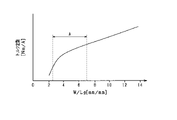
- W width in the circumferential direction
- Lg radial distance between the magnet and the armature core
- the field magnet is a surface magnet type field magnet and has a magnet for the number of poles in the circumferential direction, and the magnet is at the center of the magnetic pole.
- On the side of a certain d-axis it is oriented so that the direction of the axis of easy magnetization is parallel to the d-axis as compared with the side of the q-axis which is the boundary of the magnetic poles, or it faces each other and the inflow / outflow surface of the magnetic flux.
- the magnet easy axis is tilted with respect to the pair of working surfaces, and the tilting direction is such that the magnet winding side is tilted with respect to the d-axis so as to approach the d-axis. ..
- the armature winding is configured to use a partial winding formed by winding a wire material multiple times, it is possible to reduce the eddy current loss.
- the conducting wire material is composed of a stranded wire in which a plurality of strands are twisted together, a further effect of reducing the eddy current can be obtained.
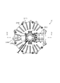
- FIG. 1 is a perspective view showing the entire rotary electric machine according to the first embodiment.
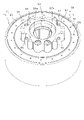
- FIG. 2 is a plan view of the rotary electric machine.
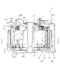
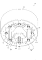
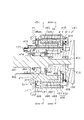
- FIG. 3 is a vertical cross-sectional view of the rotary electric machine.
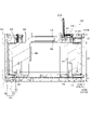
- FIG. 4 is a cross-sectional view of the rotary electric machine.
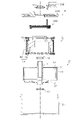
- FIG. 5 is an exploded sectional view of the rotary electric machine.
- FIG. 6 is a cross-sectional view of the rotor.
- FIG. 7 is a partial cross-sectional view showing the cross-sectional structure of the magnet unit.
- FIG. 8 is a diagram showing the relationship between the electric angle and the magnetic flux density for the magnet of the embodiment.
- FIG. 9 is a diagram showing the relationship between the electric angle and the magnetic flux density for the magnet of the comparative example.
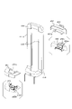
- FIG. 10 is a perspective view of the stator unit.
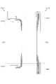
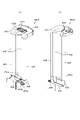
- FIG. 11 is a vertical sectional view of the stator unit.
- FIG. 12 is a perspective view of the core assembly viewed from one side in the axial direction.
- FIG. 13 is a perspective view of the core assembly viewed from the other side in the axial direction.
- FIG. 14 is a cross-sectional view of the core assembly.
- FIG. 15 is an exploded cross-sectional view of the core assembly.
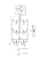
- FIG. 16 is a circuit diagram showing a connection state of partial windings in each of the three-phase windings.
- FIG. 17 is a side view showing the first coil module and the second coil module side by side in comparison.
- FIG. 18 is a side view showing the first partial winding and the second partial winding side by side in comparison.
- FIG. 19 is a diagram showing the configuration of the first coil module.
- FIG. 20 is a sectional view taken along line 20-20 in FIG. 19 (a).
- FIG. 21 is a perspective view showing the configuration of the insulating cover.
- FIG. 22 is a diagram showing the configuration of the second coil module.
- FIG. 23 is a sectional view taken along line 23-23 in FIG. 22 (a).
- FIG. 24 is a perspective view showing the configuration of the insulating cover.
- FIG. 25 is a diagram showing overlapping positions of film materials in a state where the coil modules are arranged in the circumferential direction.
- FIG. 26 is a plan view showing the assembled state of the first coil module with respect to the core assembly.
- FIG. 27 is a plan view showing the assembled state of the first coil module and the second coil module with respect to the core assembly.
- FIG. 28 is a vertical cross-sectional view showing a fixed state by the fixing pin.
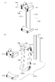
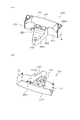
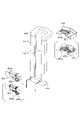
- FIG. 29 is a perspective view of the bus bar module.
- FIG. 30 is a cross-sectional view showing a part of a vertical cross section of the bus bar module.
- FIG. 31 is a perspective view showing a state in which the bus bar module is assembled to the stator holder.
- FIG. 32 is a vertical sectional view of a fixed portion for fixing the bus bar module.
- FIG. 33 is a vertical sectional view showing a state in which the relay member is attached to the housing cover.
- FIG. 34 is a perspective view of the relay member.
- FIG. 35 is an electric circuit diagram showing a control system of a rotary electric machine.
- FIG. 36 is a functional block diagram showing a current feedback control process by the control device.
- FIG. 37 is a functional block diagram showing torque feedback control processing by the control device.
- FIG. 38 is a partial cross-sectional view showing the cross-sectional structure of the magnet unit in the modified example.
- FIG. 39 is a diagram showing a configuration of a stator unit having an inner rotor structure.
- FIG. 40 is a plan view showing the assembled state of the coil module with respect to the core assembly.
- FIG. 41 is a perspective view showing the entire rotary electric machine according to the second embodiment.
- FIG. 42 is a plan view of the rotary electric machine.
- FIG. 35 is an electric circuit diagram showing a control system of a rotary electric machine.
- FIG. 36 is a functional block diagram showing a current feedback control process by the control device.
- FIG. 37 is
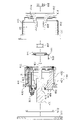
- FIG. 43 is a vertical sectional view of the rotary electric machine.
- FIG. 44 is a cross-sectional view of the rotary electric machine.
- FIG. 45 is a cross-sectional view of the rotary electric machine.
- FIG. 46 is an exploded sectional view of the rotary electric machine.
- FIG. 47 is an exploded perspective view of the stator unit.
- FIG. 48 is an exploded perspective view of the stator.
- FIG. 49 is an exploded perspective view of the stator.
- FIG. 50 is an exploded sectional view of the stator unit.
- FIG. 51 is a perspective view showing the configuration of the partial winding.
- FIG. 52 is an exploded perspective view showing the insulating cover disassembled in the partial winding.
- FIG. 53 is a perspective view showing the configuration of the partial winding.
- FIG. 53 is a perspective view showing the configuration of the partial winding.
- FIG. 54 is an exploded perspective view showing the insulating cover disassembled in the partial winding.
- FIG. 55 is a plan view showing a state in which the partial windings are arranged side by side in the circumferential direction.
- FIG. 56 is a cross-sectional view of the stator holder.
- FIG. 57 is a perspective view of the stator unit as viewed from the side of the wiring module.
- FIG. 58 is an exploded cross-sectional view showing the rotary electric machine divided into a fixed portion and a rotating portion.
- FIG. 59 is a diagram showing the direction of the magnetic path of each magnet.
- FIG. 60 is a schematic view showing a state in which the partial winding is arranged radially outside the stator core.
- FIG. 60 is a schematic view showing a state in which the partial winding is arranged radially outside the stator core.
- FIG. 61 is a cross-sectional view showing an enlarged intermediate conductor portion.
- FIG. 62 is a schematic view showing the rotor and the stator developed in a plane.
- FIG. 63 is a diagram for explaining a method of manufacturing a partial winding.
- FIG. 64 is a schematic view showing a state in which the partial winding is arranged radially outside the stator core.
- 65 is a perspective view showing a stator winding in the case of 4 poles, and
- FIG. 65 is a perspective view showing a stator winding in the case of 8 poles.
- FIG. 66 is a diagram showing the relationship between W / Lg and the torque constant.
- FIG. 67 is an enlarged cross-sectional view showing the intermediate conductor portion.
- FIG. 68 is a cross-sectional view showing an enlarged intermediate conductor portion.
- FIG. 69 is a diagram for explaining a method of manufacturing a partial winding.
- FIG. 70 is a cross-sectional view showing an enlarged intermediate conductor portion.
- FIG. 71 is a front view showing the assembled state of the partial winding with respect to the stator core.
- the rotary electric machine in this embodiment is used, for example, as a vehicle power source.
- the rotary electric machine can be widely used for industrial use, vehicle use, aircraft use, home electric appliance use, OA equipment use, game machine use, and the like.
- the parts that are the same or equal to each other are designated by the same reference numerals, and the description thereof will be used for the parts having the same reference numerals.
- the rotary electric machine 10 is a synchronous multi-phase AC motor and has an outer rotor structure (abduction structure).
- the outline of the rotary electric machine 10 is shown in FIGS. 1 to 5.
- 1 is a perspective view showing the entire rotary electric machine 10
- FIG. 2 is a plan view of the rotary electric machine 10
- FIG. 3 is a vertical sectional view of the rotary electric machine 10 (3-3 line sectional view of FIG. 2).
- FIG. 4 is a cross-sectional view of the rotary electric machine 10 (4-4 line cross-sectional view of FIG. 3)
- FIG. 5 is an exploded cross-sectional view showing the components of the rotary electric machine 10 in an exploded manner.
- the direction in which the rotary shaft 11 extends is the axial direction
- the direction in which the rotary shaft 11 extends radially from the center of the rotary shaft 11 is the radial direction
- the direction in which the rotary shaft 11 extends in a circumferential shape is the circumference. The direction.
- the rotary electric machine 10 is roughly divided into a rotary electric machine main body having a rotor 20, a stator unit 50 and a bus bar module 200, and a housing 241 and a housing cover 242 provided so as to surround the rotary electric machine main body.
- Each of these members is arranged coaxially with the rotating shaft 11 integrally provided on the rotor 20, and is assembled in the axial direction in a predetermined order to form the rotating electric machine 10.
- the rotating shaft 11 is supported by a pair of bearings 12 and 13 provided on the stator unit 50 and the housing 241 respectively, and can rotate in that state.
- the bearings 12 and 13 are, for example, radial ball bearings having an inner ring, an outer ring, and a plurality of balls arranged between them.
- the rotation of the rotating shaft 11 causes, for example, the axle of the vehicle to rotate.
- the rotary electric machine 10 can be mounted on a vehicle by fixing the housing 241 to a vehicle body frame or the like.
- the stator unit 50 is provided so as to surround the rotary shaft 11, and the rotor 20 is arranged on the radial outside of the stator unit 50.
- the stator unit 50 has a stator 60 and a stator holder 70 assembled radially inside the stator.
- the rotor 20 and the stator 60 are arranged so as to face each other in the radial direction with an air gap in between, and the rotor 20 rotates integrally with the rotating shaft 11 so that the rotor 20 is radially outside the stator 60.
- the rotor 20 corresponds to a "field magnet” and the stator 60 corresponds to an "armature".
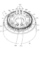
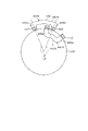
- FIG. 6 is a vertical cross-sectional view of the rotor 20.
- the rotor 20 has a substantially cylindrical rotor carrier 21 and an annular magnet unit 22 fixed to the rotor carrier 21.
- the rotor carrier 21 has a cylindrical portion 23 having a cylindrical shape and an end plate portion 24 provided at one end in the axial direction of the cylindrical portion 23, and is configured by integrating them. ..
- the rotor carrier 21 functions as a magnet holding member, and the magnet unit 22 is annularly fixed inside the cylindrical portion 23 in the radial direction.
- a through hole 24a is formed in the end plate portion 24, and the rotating shaft 11 is fixed to the end plate portion 24 by a fastener 25 such as a bolt in a state of being inserted into the through hole 24a.
- the rotary shaft 11 has a flange 11a extending in a direction intersecting (orthogonal) in the axial direction, and the rotor carrier 21 is attached to the rotary shaft 11 in a state where the flange 11a and the end plate portion 24 are surface-bonded. Is fixed.
- the magnet unit 22 has a cylindrical magnet holder 31, a plurality of magnets 32 fixed to the inner peripheral surface of the magnet holder 31, and on both sides in the axial direction opposite to the end plate portion 24 of the rotor carrier 21. It has a fixed end plate 33.
- the magnet holder 31 has the same length dimension as the magnet 32 in the axial direction.
- the magnet 32 is provided in the magnet holder 31 in a state of being surrounded from the outside in the radial direction.
- the magnet holder 31 and the magnet 32 are fixed in contact with the end plate 33 at one end in the axial direction.
- the magnet unit 22 corresponds to the "magnet portion".
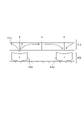
- FIG. 7 is a partial cross-sectional view showing the cross-sectional structure of the magnet unit 22.
- the direction of the easy axis of magnetization of the magnet 32 is indicated by an arrow.
- the magnets 32 are arranged side by side so that the polarities change alternately along the circumferential direction of the rotor 20.
- the magnet unit 22 has a plurality of magnetic poles in the circumferential direction.
- the magnet 32 is a polar anisotropic permanent magnet, and uses a sintered neodymium magnet having an intrinsic coercive force of 400 [kA / m] or more and a residual magnetic flux density Br of 1.0 [T] or more. It is configured.
- the peripheral surface of the magnet 32 on the inner side in the radial direction (on the stator 60 side) is the magnetic flux acting surface 34 on which magnetic flux is exchanged.
- the magnet unit 22 concentrates the magnetic flux in the region near the d-axis, which is the center of the magnetic pole, on the magnetic flux acting surface 34 of the magnet 32.
- the direction of the easy magnetization axis is different between the d-axis side (the part closer to the d-axis) and the q-axis side (the part closer to the q-axis), and the easy-magnetization axis is different on the d-axis side.
- the direction of is parallel to the d-axis, and the direction of the easy magnetization axis is orthogonal to the q-axis on the q-axis side.
- an arcuate magnetic path is formed along the direction of the easy magnetization axis.
- the magnet 32 is configured to be oriented so that the direction of the easy magnetization axis is parallel to the d-axis on the d-axis side, which is the center of the magnetic pole, as compared with the q-axis side, which is the magnetic pole boundary.
- the magnet magnetic path length is longer than the radial thickness dimension of the magnet 32.
- the permeance of the magnet 32 is increased, and it is possible to exert the same ability as a magnet having a large amount of magnets while having the same amount of magnets.
- the magnet 32 constitutes one magnetic pole with two adjacent magnets in the circumferential direction as a set. That is, the plurality of magnets 32 arranged in the circumferential direction in the magnet unit 22 have split surfaces on the d-axis and the q-axis, respectively, and the magnets 32 are arranged in contact with each other or in close proximity to each other. .. As described above, the magnet 32 has an arcuate magnet magnetic path, and the north pole and the south pole face each other with the magnets 32 adjacent to each other in the circumferential direction on the q axis. Therefore, it is possible to improve the permeance in the vicinity of the q-axis. Further, since the magnets 32 on both sides of the q-axis attract each other, each of these magnets 32 can maintain a contact state with each other. Therefore, it also contributes to the improvement of permeance.
- the magnet unit 22 magnetic flux flows in an arc shape between adjacent N and S poles due to each magnet 32, so that the magnet path is longer than that of, for example, a radial anisotropic magnet. Therefore, as shown in FIG. 8, the magnetic flux density distribution is close to that of a sine wave. As a result, unlike the magnetic flux density distribution of the radial anisotropic magnet shown as a comparative example in FIG. 9, the magnetic flux can be concentrated on the center side of the magnetic pole, and the torque of the rotary electric machine 10 can be increased. .. Further, it can be confirmed that the magnet unit 22 of the present embodiment has a difference in the magnetic flux density distribution as compared with the conventional Halbach array magnet. In FIGS.
- the horizontal axis represents the electric angle and the vertical axis represents the magnetic flux density. Further, in FIGS. 8 and 9, 90 ° on the horizontal axis indicates the d-axis (that is, the center of the magnetic pole), and 0 ° and 180 ° on the horizontal axis indicate the q-axis.
- each magnet 32 having the above configuration the magnet magnetic flux in the d-axis is strengthened in the magnet unit 22, and the magnetic flux change in the vicinity of the q-axis is suppressed.
- the magnet unit 22 in which the change in the surface magnetic flux from the q-axis to the d-axis is gentle at each magnetic pole.
- the sine wave matching rate of the magnetic flux density distribution may be, for example, a value of 40% or more. By doing so, it is possible to surely improve the amount of magnetic flux in the central portion of the waveform as compared with the case of using a radial alignment magnet or a parallel alignment magnet having a sine wave matching ratio of about 30%. Further, if the sine wave matching factor is 60% or more, the amount of magnetic flux in the central portion of the waveform can be surely improved as compared with the magnetic flux concentrated arrangement such as the Halbach array.
- the magnetic flux density changes sharply near the q-axis.
- the steeper the change in the magnetic flux density the more the eddy current increases in the stator winding 61 of the stator 60, which will be described later. Further, the change in magnetic flux on the stator winding 61 side is also steep.
- the magnetic flux density distribution is a magnetic flux waveform close to a sine wave. Therefore, the change in the magnetic flux density near the q-axis is smaller than the change in the magnetic flux density of the radial anisotropic magnet. This makes it possible to suppress the generation of eddy currents.
- a recess 35 is formed on the outer peripheral surface in the radial direction in a predetermined range including the d-axis
- a recess 36 is formed in a predetermined range including the q-axis on the inner peripheral surface in the radial direction. ing.
- the magnetic path is shortened near the d-axis on the outer peripheral surface of the magnet 32, and the magnetic path is shortened near the q-axis on the inner peripheral surface of the magnet 32. .. Therefore, in consideration of the fact that it becomes difficult to generate a sufficient magnet magnetic flux in a place where the magnet magnetic path length is short in the magnet 32, the magnet is deleted in the place where the magnet magnetic flux is weak.
- the magnet unit 22 may be configured to use the same number of magnets 32 as the magnetic poles.
- the magnet 32 is provided as one magnet between the d-axis which is the center of each magnetic pole in two magnetic poles adjacent to each other in the circumferential direction.
- the magnet 32 has a configuration in which the center in the circumferential direction is the q-axis and the magnet 32 has a split surface on the d-axis.
- the magnet 32 may be configured such that the center in the circumferential direction is the d-axis instead of the configuration in which the center in the circumferential direction is the q-axis.
- a configuration using an annular magnet connected in an annular shape may be used.
- a resolver 41 as a rotation sensor is provided at an end portion (upper end portion in the figure) opposite to the coupling portion with the rotor carrier 21 on both sides of the rotation shaft 11 in the axial direction.
- the resolver 41 includes a resolver rotor fixed to the rotating shaft 11 and a resolver stator arranged so as to face each other on the radial outer side of the resolver rotor.
- the resolver rotor has a disk ring shape, and is provided coaxially with the rotating shaft 11 with the rotating shaft 11 inserted therein.
- the resolver stator has a stator core and a stator coil, and is fixed to the housing cover 242.
- FIG. 10 is a perspective view of the stator unit 50
- FIG. 11 is a vertical sectional view of the stator unit 50. Note that FIG. 11 is a vertical cross-sectional view at the same position as in FIG.
- the stator unit 50 has, as an outline, a stator 60 and a stator holder 70 on the inner side in the radial direction thereof. Further, the stator 60 has a stator winding 61 and a stator core 62. Then, the stator core 62 and the stator holder 70 are integrated and provided as a core assembly CA, and a plurality of partial windings 151 constituting the stator winding 61 are assembled to the core assembly CA.
- the stator winding 61 corresponds to the "armature winding”
- the stator core 62 corresponds to the "armature core”
- the stator holder 70 corresponds to the "armature holding member”.
- the core assembly CA corresponds to the "support member”.
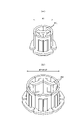
- FIG. 12 is a perspective view of the core assembly CA viewed from one side in the axial direction
- FIG. 13 is a perspective view of the core assembly CA viewed from the other side in the axial direction
- FIG. 14 is a cross section of the core assembly CA.
- FIG. 15 is an exploded cross-sectional view of the core assembly CA.
- the core assembly CA has a stator core 62 and a stator holder 70 assembled radially inside the stator core 62 as described above. So to speak, the stator core 62 is integrally assembled on the outer peripheral surface of the stator holder 70.
- the stator core 62 is configured as a core sheet laminated body in which core sheets 62a made of magnetic steel sheets, which are magnetic materials, are laminated in the axial direction, and has a cylindrical shape having a predetermined thickness in the radial direction.
- a stator winding 61 is assembled on the radial outer side of the stator core 62 on the rotor 20 side.
- the outer peripheral surface of the stator core 62 has a curved surface without unevenness.
- the stator core 62 functions as a back yoke.
- the stator core 62 is configured by, for example, a plurality of core sheets 62a punched out in an annular plate shape and laminated in the axial direction. However, a stator core 62 having a helical core structure may be used.
- stator core 62 having a helical core structure
- a strip-shaped core sheet is used, and the core sheet is wound in an annular shape and laminated in the axial direction to form a cylindrical stator core 62 as a whole. Has been done.
- the stator 60 has a slotless structure having no teeth for forming a slot, and the configuration uses any of the following (A) to (C). It may be a thing.
- a conductor-to-conductor member is provided between each conductor portion (intermediate conductor portion 152 described later) in the circumferential direction, and the width dimension of the conductor-to-lead member in one magnetic pole in the circumferential direction is provided as the conductor-to-conductor member.
- the saturation magnetic flux density of the conductor-to-conductor member is Bs
- the width dimension in the circumferential direction of the magnet 32 at one magnetic pole is Wm
- the residual magnetic flux density of the magnet 32 is Br
- a magnetic material is used.
- the stator 60 has a configuration in which no conductor-to-conductor member is provided between the conductor portions (intermediate conductor portions 152) in the circumferential direction.
- the stator holder 70 has an outer cylinder member 71 and an inner cylinder member 81, and the outer cylinder member 71 is radially outside and the inner cylinder member 81 is radially inside. It is configured by being assembled integrally.
- Each of these members 71 and 81 is made of, for example, a metal such as aluminum or cast iron, or carbon fiber reinforced plastic (CFRP).
- the outer cylinder member 71 is a cylindrical member having a perfect circular curved surface on both the outer peripheral surface and the inner peripheral surface, and an annular flange 72 extending inward in the radial direction is formed on one end side in the axial direction.
- the flange 72 is formed with a plurality of protrusions 73 extending inward in the radial direction at predetermined intervals in the circumferential direction (see FIG. 13).
- facing surfaces 74 and 75 facing the inner cylinder member 81 in the axial direction are formed on one end side and the other end side in the axial direction, respectively, and the facing surfaces 74 and 75 are annular.
- An annular grooves 74a and 75a extending to the surface are formed.
- the inner cylinder member 81 is a cylindrical member having an outer diameter dimension smaller than the inner diameter dimension of the outer cylinder member 71, and its outer peripheral surface is a circular curved surface concentric with the outer cylinder member 71.
- An annular flange 82 extending radially outward is formed on one end side of the inner cylinder member 81 in the axial direction.
- the inner cylinder member 81 is assembled to the outer cylinder member 71 in a state of being in axial contact with the facing surfaces 74 and 75 of the outer cylinder member 71. As shown in FIG. 13, the outer cylinder member 71 and the inner cylinder member 81 are assembled to each other by fasteners 84 such as bolts.
- a plurality of protruding portions 83 extending inward in the radial direction are formed at predetermined intervals in the circumferential direction, and the axial end surface of the protruding portions 83 and the outer cylinder are formed.
- the protruding portions 73, 83 are fastened to each other by the fastener 84 in a state where the protruding portion 73 of the member 71 is overlapped with each other.
- the outer cylinder member 71 and the inner cylinder member 81 are assembled to each other, there is an annular gap between the inner peripheral surface of the outer cylinder member 71 and the outer peripheral surface of the inner cylinder member 81. It is formed, and the gap space is a refrigerant passage 85 through which a refrigerant such as cooling water flows.
- the refrigerant passage 85 is provided in an annular shape in the circumferential direction of the stator holder 70. More specifically, the inner cylinder member 81 is provided with a passage forming portion 88 that protrudes radially inward on the inner peripheral side thereof and has an inlet side passage 86 and an outlet side passage 87 formed therein.
- Each of the passages 86 and 87 is open to the outer peripheral surface of the inner cylinder member 81. Further, on the outer peripheral surface of the inner cylinder member 81, a partition portion 89 for partitioning the refrigerant passage 85 into an inlet side and an outlet side is provided. As a result, the refrigerant flowing in from the inlet side passage 86 flows in the refrigerant passage 85 in the circumferential direction, and then flows out from the outlet side passage 87.
- FIG. 12 shows an entrance opening 86a leading to the entrance side passage 86 and an exit opening 87a leading to the exit side passage 87.
- the inlet side passage 86 and the outlet side passage 87 are connected to the inlet port 244 and the outlet port 245 (see FIG. 1) attached to the housing cover 242, and the refrigerant enters and exits through the respective ports 244 and 245. It has become like.
- Sealing materials 101 and 102 for suppressing leakage of the refrigerant in the refrigerant passage 85 are provided at the joint portion between the outer cylinder member 71 and the inner cylinder member 81 (see FIG. 15).
- the sealing materials 101 and 102 are, for example, O-rings, which are accommodated in the annular grooves 74a and 75a of the outer cylinder member 71 and are provided in a state of being compressed by the outer cylinder member 71 and the inner cylinder member 81. There is.
- the inner cylinder member 81 has an end plate portion 91 on one end side in the axial direction, and the end plate portion 91 has a hollow cylindrical boss portion 92 extending in the axial direction. It is provided.
- the boss portion 92 is provided so as to surround the insertion hole 93 for inserting the rotating shaft 11.
- the boss portion 92 is provided with a plurality of fastening portions 94 for fixing the housing cover 242.
- the end plate portion 91 is provided with a plurality of support column portions 95 extending in the axial direction on the radial outer side of the boss portion 92.
- the support column 95 is a portion that serves as a fixing portion for fixing the bus bar module 200, and the details thereof will be described later.
- the boss portion 92 is a bearing holding member for holding the bearing 12, and the bearing 12 is fixed to the bearing fixing portion 96 provided on the inner peripheral portion thereof (see FIG. 3).
- recesses 105 and 106 used for fixing a plurality of coil modules 150 are formed in the outer cylinder member 71 and the inner cylinder member 81.
- a plurality of axial end faces of the inner cylinder member 81 are provided at equal intervals in the circumferential direction.
- a recess 105 is formed.
- a plurality of recesses 106 are formed at equal intervals in the circumferential direction on the axial end surface of the outer cylinder member 71, specifically, the axially outer end surface of the flange 72.
- These recesses 105 and 106 are provided so as to be aligned on a virtual circle concentric with the core assembly CA.
- the recesses 105 and 106 are provided at the same positions in the circumferential direction, respectively, and the intervals and the number thereof are also the same.
- the stator core 62 is assembled in a state where a compressive force in the radial direction is generated with respect to the stator holder 70 in order to secure the strength of the assembly with respect to the stator holder 70.
- the stator core 62 is fitted and fixed to the stator holder 70 with a predetermined tightening margin by shrink fitting or press fitting.
- the stator core 62 and the stator holder 70 are assembled in a state where radial stress is generated from one of them to the other.
- stator 60 when increasing the torque of the rotary electric machine 10, for example, it is conceivable to increase the diameter of the stator 60, and in such a case, the stator is used to strengthen the coupling of the stator core 62 to the stator holder 70. The tightening force of the core 62 is increased. However, if the compressive stress (in other words, the residual stress) of the stator core 62 is increased, there is a concern that the stator core 62 may be damaged.
- stator core 62 and the stator holder 70 are fitted and fixed to each other with a predetermined tightening allowance.
- a regulating portion is provided to regulate the displacement of the stator core 62 in the circumferential direction by engaging in the circumferential direction. That is, as shown in FIGS. 12 to 14, a plurality of engagements as a restricting portion are provided between the stator core 62 and the outer cylinder member 71 of the stator holder 70 in the radial direction at predetermined intervals in the circumferential direction.
- a member 111 is provided, and the engaging member 111 suppresses the positional deviation between the stator core 62 and the stator holder 70 in the circumferential direction.
- a recess may be provided in at least one of the stator core 62 and the outer cylinder member 71, and the engaging member 111 may be engaged in the recess.
- a convex portion may be provided on either the stator core 62 or the outer cylinder member 71.
- the stator core 62 and the stator holder 70 are fitted and fixed with a predetermined tightening allowance, and mutual circumferential displacement is regulated by the regulation of the engaging member 111. It is provided in a state of being. Therefore, even if the tightening allowance in the stator core 62 and the stator holder 70 is relatively small, the displacement of the stator core 62 in the circumferential direction can be suppressed. Further, since the desired displacement suppressing effect can be obtained even if the tightening allowance is relatively small, damage to the stator core 62 due to an excessively large tightening allowance can be suppressed. As a result, the displacement of the stator core 62 can be appropriately suppressed.
- An annular internal space is formed on the inner peripheral side of the inner cylinder member 81 so as to surround the rotation shaft 11, and in the internal space, for example, electrical components constituting an inverter as a power converter are arranged. May be good.
- the electric component is, for example, an electric module in which a semiconductor switching element or a capacitor is packaged.
- the plurality of protruding portions 83 may be eliminated or the protruding height of the protruding portions 83 may be reduced, thereby expanding the internal space on the inner peripheral side of the inner cylinder member 81. It is possible.
- stator winding 61 assembled to the core assembly CA The state in which the stator winding 61 is assembled to the core assembly CA is as shown in FIGS. 10 and 11, and the stator is attached to the radial outside of the core assembly CA, that is, the radial outside of the stator core 62.
- a plurality of partial windings 151 constituting the winding 61 are assembled in a state of being arranged in the circumferential direction.
- the stator winding 61 has a plurality of phase windings, and the phase windings of each phase are arranged in a predetermined order in the circumferential direction to form a cylindrical shape (annular).
- the stator winding 61 has a three-phase phase winding by using U-phase, V-phase, and W-phase phase windings.
- the stator 60 has a portion corresponding to the coil side CS that faces the magnet unit 22 in the rotor 20 in the axial direction in the axial direction, and a coil end that is outside the coil side CS in the axial direction. It has a part corresponding to CE.
- the stator core 62 is provided in a range corresponding to the coil side CS in the axial direction.
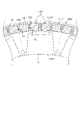
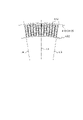
- each phase winding of each phase has a plurality of partial windings 151 (see FIG. 16), and the partial windings 151 are individually provided as coil modules 150. That is, the coil module 150 is configured by integrally providing partial windings 151 in the phase windings of each phase, and the stator winding 61 is configured by a predetermined number of coil modules 150 according to the number of poles. There is. By arranging the coil modules 150 (partial winding 151) of each phase in a predetermined order in the circumferential direction, the conductors of each phase are arranged in a predetermined order in the coil side CS of the stator winding 61. It has become.
- FIG. 10 shows the order of arrangement of the U-phase, V-phase, and W-phase conductors in the coil side CS. In the present embodiment, the number of magnetic poles is 24, but the number is arbitrary.
- the phase windings of each phase are configured by connecting the partial windings 151 of each coil module 150 in parallel or in series for each phase.
- FIG. 16 is a circuit diagram showing a connection state of the partial winding 151 in each of the three-phase windings.
- FIG. 16 shows a state in which the partial windings 151 in the phase windings of each phase are connected in parallel.
- the coil module 150 is assembled on the radial outer side of the stator core 62.
- the coil module 150 is assembled in a state where both ends in the axial direction are projected outward in the axial direction (that is, the coil end CE side) from the stator core 62. That is, the stator winding 61 has a portion corresponding to the coil end CE protruding outward in the axial direction from the stator core 62, and a portion corresponding to the coil side CS on the inner side in the axial direction. ..
- the coil module 150 has two types of shapes, one of which has a shape in which the partial winding 151 is bent in the radial direction, that is, toward the stator core 62 in the coil end CE.
- the partial winding 151 is not bent inward in the radial direction and has a shape extending linearly in the axial direction.
- the partial winding 151 having a bent shape on both ends in the axial direction is referred to as a "first partial winding 151A”
- the coil module 150 having the first partial winding 151A is referred to as a "first coil”. Also referred to as "module 150A”.
- the partial winding 151 having no bending shape on both ends in the axial direction is also referred to as a "second partial winding 151B", and the coil module 150 having the second partial winding 151B is also referred to as a "second coil module 150B”. ..
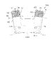
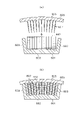
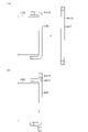
- FIG. 17 is a side view showing the first coil module 150A and the second coil module 150B side by side in comparison
- FIG. 18 shows the first partial winding 151A and the second partial winding 151B side by side. It is a side view showing side by side and contrasting.
- the coil modules 150A and 150B and the partial windings 151A and 151B have different axial lengths and different end shapes on both sides in the axial direction.
- the first partial winding 151A has a substantially C shape in the side view
- the second partial winding 151B has a substantially I shape in the side view.
- the first partial winding 151A is equipped with insulating covers 161, 162 as “first insulating covers” on both sides in the axial direction
- the second partial winding 151B is equipped with “second insulating covers” on both sides in the axial direction. Insulation covers 163 and 164 are attached.
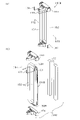
- FIG. 19A is a perspective view showing the configuration of the first coil module 150A
- FIG. 19B is a perspective view showing the components of the first coil module 150A in an exploded manner
- FIG. 20 is a sectional view taken along line 20-20 in FIG. 19 (a).
- the first coil module 150A has a first partial winding 151A configured by multiple winding of a conducting wire material CR and a first partial winding 151A thereof in the axial direction. It has insulating covers 161, 162 attached to one end side and the other end side.
- the insulating covers 161, 162 are formed of an insulating material such as synthetic resin.
- the first partial winding 151A has a pair of intermediate conductor portions 152 provided in parallel and linearly with each other, and a pair of crossover portions 153A connecting the pair of intermediate conductor portions 152 at both ends in the axial direction. , These pair of intermediate conductor portions 152 and the pair of crossover portions 153A form an annular shape.
- the pair of intermediate conductors 152 are provided so as to be separated by a predetermined coil pitch, and the intermediate conductors 152 of the partial winding 151 of the other phase can be arranged between the pair of intermediate conductors 152 in the circumferential direction. It has become.
- the pair of intermediate conductors 152 are provided so as to be separated by two coil pitches, and one intermediate conductor 152 in the other two-phase partial winding 151 is arranged between the pair of intermediate conductors 152. It is configured to be.
- the pair of crossover portions 153A have the same shape on both sides in the axial direction, and both are provided as portions corresponding to the coil end CE (see FIG. 11). Each crossover portion 153A is provided so as to be bent in a direction orthogonal to the intermediate conductor portion 152, that is, in a direction orthogonal to the axial direction.
- the first partial winding 151A has crossover portions 153A on both sides in the axial direction
- the second partial winding 151B has crossover portions 153B on both sides in the axial direction.
- the crossover portions 153A and 153B of the partial windings 151A and 151B are different in shape from each other, and in order to clarify the distinction, the crossover portion 153A of the first partial winding 151A is referred to as a "first crossover portion 153A”.
- the crossover portion 153B of the second partial winding 151B is also referred to as "second crossover portion 153B".
- the intermediate conductor portion 152 is provided as a coil side conductor portion arranged one by one in the circumferential direction in the coil side CS. Further, the crossover portions 153A and 153B are provided as coil end conductor portions in the coil end CE for connecting the intermediate conductor portions 152 having the same phase at two positions different in the circumferential direction.
- the first partial winding 151A is formed by winding the conducting wire material CR multiple times so that the cross section of the conducting wire gathering portion becomes a quadrangle.
- FIG. 20 shows a cross section of the intermediate conducting wire portion 152, and the conducting wire material CR is multiplely wound around the intermediate conducting wire portion 152 so as to be aligned in the circumferential direction and the radial direction. That is, in the first partial winding 151A, the conductors CR are arranged in a plurality of rows in the circumferential direction and in a plurality of rows in the radial direction in the intermediate conductor portion 152 so that the cross section becomes substantially rectangular. It is formed.
- the tip of the first crossover portion 153A is configured to be wound in multiple directions so that the conductor CRs are aligned in the axial direction and the radial direction due to the bending in the radial direction.
- the first partial winding 151A is configured by winding the conductor CR by concentric winding.
- the method of winding the conductor CR is arbitrary, and instead of concentric winding, the conductor CR may be wound multiple times by alpha winding.
- the end of the conductor CR is formed from one of the first crossovers 153A (the upper first crossover 153A in FIG. 19B). It is pulled out, and its end portion is a winding end portion 154, 155.
- the winding end portions 154 and 155 are portions where the winding start and winding end of the conductor material CR, respectively.
- One of the winding ends 154 and 155 is connected to the current input / output terminal, and the other is connected to the neutral point.
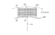
- each intermediate conducting wire portion 152 is provided with a sheet-shaped insulating coating 157 covered with the intermediate conducting wire portion 152.
- FIG. 19A shows the first coil module 150A in a state where the intermediate conductor portion 152 is covered with the insulating coating portion 157 and the intermediate conductor portion 152 is present inside the insulating coating portion 157.
- the corresponding portion is referred to as an intermediate conductor portion 152 (the same applies to FIG. 22A described later).
- the insulating coating 157 uses a film material FM having at least the length of the insulating coating range in the intermediate wire portion 152 as an axial dimension, and the film material FM is wound around the intermediate conductor portion 152. It is provided.
- the film material FM is made of, for example, a PEN (polyethylene naphthalate) film. More specifically, the film material FM includes a film base material and an adhesive layer provided on one side of both surfaces of the film base material and having foamability. Then, the film material FM is wound around the intermediate conductor portion 152 in a state of being adhered by the adhesive layer. It is also possible to use a non-foaming adhesive as the adhesive layer.
- the intermediate conductor portion 152 has a substantially rectangular cross section due to the arrangement of the conductor material CRs in the circumferential direction and the radial direction, and the film material FM is formed around the intermediate conductor portion 152.
- the insulating coating 157 is provided by covering the peripheral ends in an overlapped state.
- the film material FM is a rectangular sheet whose vertical dimension is longer than the axial length of the intermediate conductor portion 152 and whose horizontal dimension is longer than one circumference of the intermediate conductor portion 152, according to the cross-sectional shape of the intermediate conductor portion 152. It is wound around the intermediate conductor portion 152 with a crease.
- the gap between the conductor material CR of the intermediate conductor portion 152 and the film base material is filled by foaming in the adhesive layer. Further, in the overlapping portion OL of the film material FM, the peripheral ends of the film material FM are joined by an adhesive layer.
- an insulating coating 157 is provided so as to cover all of the two circumferential side surfaces and the two radial side surfaces.
- the insulating coating 157 surrounding the intermediate conductor portion 152 has a film on one of the two circumferential side surfaces of the intermediate conductor portion 152, that is, the portion facing the intermediate conductor portion 152 in the partial winding 151 of the other phase.
- An overlap portion OL in which the material FM overlaps is provided.
- the pair of intermediate conductor portions 152 are provided with overlapping portions OL on the same side in the circumferential direction.
- the range is from the intermediate conductor portion 152 to the portion covered by the insulating covers 161, 162 (that is, the portion inside the insulating covers 161, 162) in the first crossover portions 153A on both sides in the axial direction.
- the insulating coating body 157 is provided.
- the range of AX1 is a portion not covered by the insulating covers 161, 162, and the insulating coating 157 is provided in a range extended vertically from the range AX1. ..
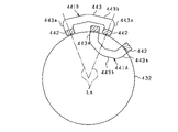
- the insulating cover 161 is mounted on the first crossover 153A on one axial side of the first partial winding 151A, and the insulating cover 162 is mounted on the first crossover 153A on the other axial direction of the first partial winding 151A. Will be done. Of these, the configuration of the insulating cover 161 is shown in FIGS. 21 (a) and 21 (b). 21 (a) and 21 (b) are perspective views of the insulating cover 161 viewed from two different directions.
- the insulating cover 161 includes a pair of side surface portions 171 which are side surfaces in the circumferential direction, an outer surface portion 172 on the outer side in the axial direction, and an inner surface portion 173 on the inner side in the axial direction. It has a front surface portion 174 on the inner side in the radial direction.
- Each of these parts 171 to 174 is formed in a plate shape, and is connected to each other in a three-dimensional shape so that only the radial outer side is open.
- Each of the pair of side surface portions 171 is provided so as to extend toward the axis of the core assembly CA in the assembled state with the core assembly CA.
- the outer surface portion 172 is provided with an opening 175a for pulling out the winding end portion 154 of the first partial winding 151A
- the front surface portion 174 is provided with the winding end of the first partial winding 151A.
- An opening 175b for pulling out the portion 155 is provided. In this case, one winding end portion 154 is drawn out from the outer surface portion 172 in the axial direction, while the other winding end portion 155 is drawn out from the front surface portion 174 in the radial direction.
- the pair of side surface portions 171 has a semicircular shape extending in the axial direction at positions at both ends in the circumferential direction of the front surface portion 174, that is, at positions where each side surface portion 171 and the front surface portion 174 intersect.
- a recess 177 is provided.
- the outer surface portion 172 is provided with a pair of protrusions 178 extending in the axial direction at positions symmetrical to both sides in the circumferential direction with respect to the center line of the insulating cover 161 in the circumferential direction.
- the first crossover portion 153A of the first partial winding 151A has a curved shape that is convex in the radial direction, that is, toward the core assembly CA, out of the radial inside and outside. In such a configuration, a gap is formed between the first crossover portions 153A adjacent to each other in the circumferential direction so as to be wider toward the tip end side of the first crossover portion 153A.
- the recess 177 is provided on the side surface portion 171 of the insulating cover 161 at a position outside the curved portion of the first crossover portion 153A by utilizing the gap between the first crossover portions 153A arranged in the circumferential direction. It has a structure.
- the first partial winding 151A may be provided with a temperature detection unit (thermistor), and in such a configuration, the insulating cover 161 may be provided with an opening for drawing out a signal line extending from the temperature detection unit.
- the temperature detection unit can be suitably accommodated in the insulating cover 161.
- the insulating cover 162 on the other side in the axial direction has substantially the same configuration as the insulating cover 161.
- the insulating cover 162 has a pair of side surface portions 171, an outer surface portion 172 on the outer side in the axial direction, an inner surface portion 173 on the inner side in the axial direction, and a front surface portion 174 on the inner side in the radial direction, similarly to the insulating cover 161. ..
- the pair of side surface portions 171 are provided with semicircular recesses 177 at positions at both ends in the circumferential direction of the front surface portion 174, and the outer surface portion 172 is provided with a pair of protrusions 178. ..
- the difference from the insulating cover 161 is that the insulating cover 162 does not have an opening for pulling out the winding ends 154 and 155 of the first partial winding 151A.
- the height dimension in the axial direction (that is, the width dimension in the axial direction in the pair of side surface portions 171 and the front surface portion 174) is different.
- the axial height dimension W11 of the insulating cover 161 and the axial height dimension W12 of the insulating cover 162 are W11> W12. That is, when the conductor material CR is wound multiple times, it is necessary to switch (lane change) the winding stage of the conductor material CR in a direction orthogonal to the winding winding direction (circumferential direction), which is caused by the switching. It is conceivable that the winding width will increase.
- the insulating cover 161 is a portion that covers the first crossing portion 153A on the side including the winding start and winding end of the conducting wire material CR, and includes the winding start and winding end of the conducting wire material CR.
- the winding allowance (overlapping allowance) of the conductor material CR is larger than that of the other portions, and as a result, the winding width may be increased.
- the axial height dimension W11 of the insulating cover 161 is larger than the axial height dimension W12 of the insulating cover 162.
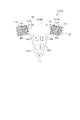
- FIG. 22A is a perspective view showing the configuration of the second coil module 150B
- FIG. 22B is a perspective view showing the components of the second coil module 150B in an exploded manner
- FIG. 23 is a cross-sectional view taken along the line 23-23 in FIG. 22 (a).
- the second coil module 150B includes a second partial winding 151B configured by multiple winding the conductor CR as in the first partial winding 151A, and a second partial winding 151B thereof.
- the second partial winding 151B has insulating covers 163 and 164 attached to one end side and the other end side in the axial direction.
- the insulating covers 163 and 164 are formed of an insulating material such as synthetic resin.
- the second partial winding 151B has a pair of intermediate conductor portions 152 provided in parallel and linearly with each other, and a pair of second crossover portions 153B connecting the pair of intermediate conductor portions 152 at both ends in the axial direction.
- the pair of intermediate conductors 152 and the pair of second crossovers 153B form an annular shape.
- the pair of intermediate conductors 152 in the second partial winding 151B has the same configuration as the intermediate conductors 152 of the first partial winding 151A.
- the pair of second crossover portions 153B has a different configuration from the first crossover portion 153A of the first partial winding 151A.
- the second crossover portion 153B of the second partial winding 151B is provided so as to extend linearly in the axial direction from the intermediate conductor portion 152 without being bent in the radial direction.
- the differences between the partial windings 151A and 151B are clearly shown in comparison.
- the end of the conductor CR is formed from one of the second crossovers 153B (the upper second crossover 153B in FIG. 22B) of the second crossovers 153B on both sides in the axial direction. It is pulled out, and its end portion is a winding end portion 154, 155. Then, in the second partial winding 151B as well as the first partial winding 151A, one of the winding ends 154 and 155 is connected to the current input / output terminal, and the other is connected to the neutral point. It has become.
- each intermediate conducting wire portion 152 is provided with a sheet-shaped insulating coating 157 covered.
- the insulating coating 157 uses a film material FM having at least the length of the insulating coating range in the intermediate wire portion 152 as an axial dimension, and the film material FM is wound around the intermediate conductor portion 152. It is provided.
- the configuration of the insulating coating 157 is almost the same for each of the partial windings 151A and 151B. That is, as shown in FIG. 23, the film material FM is covered around the intermediate conductor portion 152 in a state where the end portions in the circumferential direction are overlapped.
- the insulating coating 157 is provided so as to cover all of the two circumferential side surfaces and the two radial side surfaces.
- the insulating coating 157 surrounding the intermediate conductor portion 152 has a film on one of the two circumferential side surfaces of the intermediate conductor portion 152, that is, the portion facing the intermediate conductor portion 152 in the partial winding 151 of the other phase.
- An overlap portion OL in which the material FM overlaps is provided.
- the pair of intermediate conductor portions 152 are provided with overlapping portions OL on the same side in the circumferential direction.
- the range from the intermediate conductor portion 152 to the portion covered by the insulating covers 163 and 164 in the second crossover portions 153B on both sides in the axial direction that is, the portion inside the insulating covers 163 and 164).
- the insulating coating body 157 is provided.
- the range of AX2 is a portion not covered by the insulating covers 163 and 164, and the insulating covering 157 is provided in a range extended vertically from the range AX2. ..
- the insulating coating 157 is provided in a range including a part of the crossover portions 153A and 153B. That is, the partial windings 151A and 151B are provided with an insulating coating 157 at the intermediate conductor portion 152 and the portion of the crossover portions 153A and 153B that extends linearly following the intermediate conductor portion 152. However, since the axial lengths of the partial windings 151A and 151B are different, the axial range of the insulating coating 157 is also different.
- the insulating cover 163 is mounted on the second crossover 153B on one axial side of the second partial winding 151B, and the insulating cover 164 is mounted on the second crossover 153B on the other axial direction of the second partial winding 151B. Will be done. Of these, the configuration of the insulating cover 163 is shown in FIGS. 24 (a) and 24 (b). 24 (a) and 24 (b) are perspective views of the insulating cover 163 as viewed from two different directions.
- the insulating cover 163 includes a pair of side surface portions 181 which are side surfaces in the circumferential direction, an outer surface portion 182 on the outer side in the axial direction, and a front surface portion 183 on the inner side in the radial direction. It has a rear surface portion 184 on the outer side in the radial direction.
- Each of these portions 181 to 184 is formed in a plate shape, and is connected to each other in a three-dimensional shape so that only the inner side in the axial direction is opened.
- Each of the pair of side surface portions 181 is provided so as to extend toward the axis of the core assembly CA in the assembled state with the core assembly CA.
- the front surface portion 183 is provided with an opening 185a for pulling out the winding end portion 154 of the second partial winding 151B, and the outer surface portion 182 is provided with the winding end of the second partial winding 151B.
- An opening 185b for pulling out the portion 155 is provided.
- the front surface portion 183 of the insulating cover 163 is provided with a protruding portion 186 protruding inward in the radial direction.
- the projecting portion 186 is provided at a central position between one end and the other end in the circumferential direction of the insulating cover 163 so as to project radially inward from the second crossover portion 153B.
- the protrusion 186 has a tapered shape that tapers toward the inside in the radial direction in a plan view, and a through hole 187 extending in the axial direction is provided at the tip thereof.
- the protruding portion 186 protrudes radially inward from the second crossover portion 153B and has a through hole 187 at the center position between one end and the other end in the circumferential direction of the insulating cover 163, the protruding portion 186 has a through hole 187.
- the configuration is arbitrary. However, assuming an overlapping state with the insulating cover 161 inside in the axial direction, it is desirable that the cover is formed narrow in the circumferential direction in order to avoid interference with the winding ends 154 and 155.
- the protruding portion 186 has an axially thin stepped thickness at the tip portion on the inner side in the radial direction, and a through hole 187 is provided in the thinned lower step portion 186a.
- This low step portion 186a corresponds to a portion where the height of the inner cylinder member 81 from the axial end face is lower than the height of the second crossover portion 153B in the assembled state of the second coil module 150B with respect to the core assembly CA. ..
- the protruding portion 186 is provided with a through hole 188 penetrating in the axial direction. This makes it possible to fill the space between the insulating covers 161, 163 through the through holes 188 in a state where the insulating covers 161, 163 overlap in the axial direction.
- the insulating cover 164 on the other side in the axial direction has substantially the same configuration as the insulating cover 163.
- the insulating cover 164 has a pair of side surface portions 181, an outer surface portion 182 on the outer side in the axial direction, a front surface portion 183 on the inner side in the radial direction, and a rear surface portion 184 on the outer side in the radial direction. It has a through hole 187 provided at the tip of the portion 186.
- the difference from the insulating cover 163 is that the insulating cover 164 does not have an opening for pulling out the winding ends 154 and 155 of the second partial winding 151B.
- the width dimension of the pair of side surface portions 181 in the radial direction is different.
- the radial width dimension W21 of the side surface portion 181 of the insulating cover 163 and the radial width dimension W22 of the side surface portion 181 of the insulating cover 164 are W21> W22. .. That is, of the insulating covers 163 and 164, the insulating cover 163 is a portion that covers the second crossing portion 153B on the side including the winding start and winding end of the conducting wire material CR, and includes the winding start and winding end of the conducting wire material CR.
- the winding allowance (overlapping allowance) of the conductor material CR may be larger than that of the other portions, and as a result, the winding width may be increased.
- the radial width dimension W21 of the insulating cover 163 is larger than the radial width dimension W22 of the insulating cover 164.
- the inconvenience that the number of turns of the conducting wire material CR is limited by the insulating covers 163 and 164 can be suppressed. ing.
- FIG. 25 is a diagram showing the overlap position of the film material FM in a state where the coil modules 150A and 150B are arranged in the circumferential direction.
- the intermediate conductor portion 152 is overlapped with the portion facing the intermediate conductor portion 152 in the partial winding 151 of the other phase, that is, the circumferential side surface of the intermediate conductor portion 152.
- the film material FM is covered with the film material (see FIGS. 20 and 23).
- the overlap portion OL of the film material FM is arranged on the same side (on the right side in the circumferential direction in the figure) on both sides in the circumferential direction. ing.
- the overlapping portions OL of the film material FM do not overlap each other in the circumferential direction.
- a maximum of three film material FMs are overlapped between the intermediate conductor portions 152 arranged in the circumferential direction.
- the coil modules 150A and 150B have different axial lengths, and the shapes of the crossover portions 153A and 153B of the partial windings 151A and 151B are different from each other. It is configured to be attached to the core assembly CA with the second crossover 153B of the second coil module 150B on the inside in the direction and on the outside in the axial direction.
- the insulating covers 161 to 164 the insulating covers 161 and 163 are vertically stacked on one end side in the axial direction of the coil modules 150A and 150B, and the insulating covers 162 and 164 are stacked axially on the other end side in the axial direction. In the closed state, each of these insulating covers 161 to 164 is fixed to the core assembly CA.
- FIG. 26 is a plan view showing a state in which a plurality of insulating covers 161 are arranged in the circumferential direction in a state where the first coil module 150A is assembled to the core assembly CA
- FIG. 27 is a plan view showing the first coil module 150A and the first coil module 150A to the core assembly CA. It is a top view which shows the state which a plurality of insulating covers 161, 163 are arranged in the circumferential direction in the assembled state of 2 coil modules 150B.
- FIG. 28A is a vertical sectional view showing a state before fixing by the fixing pin 191 in the assembled state of the coil modules 150A and 150B with respect to the core assembly CA
- FIG. 28B is a vertical cross-sectional view showing the state before being fixed with respect to the core assembly CA. It is a vertical sectional view which shows the state after being fixed by the fixing pin 191 in the assembled state of each coil module 150A, 150B.
- each insulating cover 161 is arranged so that the boundary line LB facing the side surface portions 171 and the recess 105 on the axial end surface of the inner cylinder member 81 coincide with each other.
- each recess 177 of the insulating cover 161 forms a through hole portion extending in the axial direction, and the through hole portion thereof is formed.
- the positions of the holes and the recesses 105 are set to match.
- the second coil module 150B is further assembled to the integral body of the core assembly CA and the first coil module 150A.
- a plurality of insulating covers 163 are arranged with the side surface portions 181 in contact with each other or in close contact with each other.
- the crossover portions 153A and 153B are arranged so as to intersect each other on a circle in which the intermediate conductor portions 152 are lined up in the circumferential direction.
- the protruding portion 186 overlaps the insulating cover 161 in the axial direction, and the through hole 187 of the protruding portion 186 is axially connected to the through hole portion formed by each recess 177 of the insulating cover 161. Will be placed.
- the protruding portion 186 of the insulating cover 163 is guided to a predetermined position by the pair of protruding portions 178 provided on the insulating cover 161 so that the through hole portion on the insulating cover 161 side and the recess 105 of the inner cylinder member 81 are guided.
- the position of the through hole 187 on the insulating cover 163 side is aligned with the above. That is, in the state where the coil modules 150A and 150B are assembled to the core assembly CA, the concave portion 177 of the insulating cover 161 is located on the back side of the insulating cover 163, so that the protruding portion with respect to the concave portion 177 of the insulating cover 161.
- the insulating cover 161 is fixed by the fixing pin 191 as a fixing member in a state of being engaged with the overlapping portion of the insulating cover 161 and the protruding portion 186 of the insulating cover 163. Will be done. More specifically, in a state where the recess 105 of the inner cylinder member 81, the recess 177 of the insulating cover 161 and the through hole 187 of the insulating cover 163 are aligned, the fixing pins are inserted into the recesses 105, 177 and the through hole 187. 191 is inserted.
- the insulating covers 161 and 163 are integrally fixed to the inner cylinder member 81.
- the coil modules 150A and 150B adjacent to each other in the circumferential direction are fixed to the core assembly CA by a common fixing pin 191 at the coil end CE.
- the fixing pin 191 is preferably made of a material having good thermal conductivity, for example, a metal pin.
- the fixing pin 191 is assembled to the lower step portion 186a of the protruding portion 186 of the insulating cover 163.
- the upper end portion of the fixing pin 191 protrudes above the lower step portion 186a, but does not protrude above the upper surface (outer surface portion 182) of the insulating cover 163.
- the fixing pin 191 is longer than the axial height dimension of the overlapping portion between the insulating cover 161 and the protruding portion 186 (lower step portion 186a) of the insulating cover 163, and has a margin for protruding upward.
- the fixing pin 191 When the fixing pin 191 is inserted into the recesses 105 and 177 and the through hole 187 (that is, when the fixing pin 191 is fixed), it may be easier to perform the work. Further, since the upper end portion of the fixing pin 191 does not protrude above the upper surface (outer surface portion 182) of the insulating cover 163, it is possible to suppress the inconvenience that the shaft length of the stator 60 becomes long due to the protruding portion of the fixing pin 191. It has become a thing.
- the adhesive is filled through the through holes 188 provided in the insulating cover 163.
- the through hole 188 is shown in the range from the upper surface to the lower surface of the insulating cover 163 for convenience, but in reality, the through hole 188 is formed in the thin plate portion formed by lightening or the like. It has a provided configuration.
- each insulating cover 161 and 163 by the fixing pin 191 is the axial end surface of the stator holder 70 radially inside (left side in the figure) from the stator core 62.
- the stator holder 70 is fixed by the fixing pin 191. That is, the first crossover portion 153A is fixed to the axial end face of the stator holder 70.
- the stator holder 70 is provided with the refrigerant passage 85, the heat generated in the first partial winding 151A is directly from the first crossover portion 153A to the vicinity of the refrigerant passage 85 of the stator holder 70. It is transmitted to.
- the fixing pin 191 is inserted into the recess 105 of the stator holder 70, and heat transfer to the stator holder 70 side is promoted through the fixing pin 191. With such a configuration, the cooling performance of the stator winding 61 is improved.
- 18 insulating covers 161, 163 are arranged so as to be stacked inside and outside the axial direction in the coil end CE, while the same number of insulating covers 161 and 163 are arranged on the axial end face of the stator holder 70.
- Recesses 105 are provided at 18 locations. The 18 recesses 105 are fixed by the fixing pin 191.
- the positions of the through holes 187 on the insulating cover 164 side match the through holes on the insulating cover 163 side and the recesses 106 on the outer cylinder member 71, and the recesses 106 and 177 are aligned.
- the fixing pin 191 By inserting the fixing pin 191 into the through hole 187, the insulating covers 162 and 164 are integrally fixed to the outer cylinder member 71.
- the first coil modules 150A and 150B When assembling the coil modules 150A and 150B to the core assembly CA, all the first coil modules 150A are attached to the outer peripheral side of the core assembly CA first, and then all the second coil modules 150B are assembled. It is preferable to perform fixing with the fixing pin 191. Alternatively, the two first coil modules 150A and the one second coil module 150B are first fixed to the core assembly CA with one fixing pin 191 and then the first coil module 150A is assembled. , The assembly of the second coil module 150B and the fixing by the fixing pin 191 may be repeated in this order.
- bus bar module 200 Next, the bus bar module 200 will be described.
- the bus bar module 200 is electrically connected to the partial winding 151 of each coil module 150 at the stator winding 61, and one end of the partial winding 151 of each phase is connected in parallel for each phase, and each partial winding thereof is connected. It is a winding connection member that connects the other end of 151 at a neutral point. 29 is a perspective view of the bus bar module 200, and FIG. 30 is a cross-sectional view showing a part of a vertical cross section of the bus bar module 200.
- the bus bar module 200 has an annular portion 201 forming an annular portion, a plurality of connection terminals 202 extending from the annular portion 201, and three input / output terminals 203 provided for each phase winding.
- the annular portion 201 is formed in an annular shape by, for example, an insulating member such as a resin.
- the annular portion 201 has a substantially annular plate shape and has laminated plates 204 laminated in multiple layers (five layers in this embodiment) in the axial direction, and each of these laminated plates 204 has a laminated plate 204.
- Four bus bars 211 to 214 are provided so as to be sandwiched between them.
- Each of the bus bars 211 to 214 has an annular shape, and is composed of a U-phase bus bar 211, a V-phase bus bar 212, a W-phase bus bar 213, and a neutral point bus bar 214. ..
- the bus bars 211 to 214 are arranged in the annular portion 201 so as to face each other in the axial direction.
- connection terminals 202 are connected to the bus bars 211 to 214 so as to project radially outward from the annular portion 201, respectively.
- a protrusion 201a extending in an annular shape is provided on the upper surface of the annular portion 201, that is, on the upper surface of the laminated plate 204 on the most surface layer side of the laminated plate 204 provided in the five layers.
- the bus bar module 200 may be provided in a state where the bus bars 211 to 214 are embedded in the annular portion 201, and the bus bars 211 to 214 arranged at predetermined intervals are integrally insert-molded. It may be a thing. Further, the arrangement of the bus bars 211 to 214 is not limited to the configuration in which all the bus bars are arranged in the axial direction and all the plate surfaces are oriented in the same direction. It may be configured to line up in a row, or to include those having different plate surface extending directions.
- connection terminals 202 are provided so as to be arranged in the circumferential direction of the annular portion 201 and to extend in the axial direction on the outer side in the radial direction.
- the connection terminal 202 includes a connection terminal connected to the U-phase bus bar 211, a connection terminal connected to the V-phase bus bar 212, a connection terminal connected to the W-phase bus bar 213, and a neutral point. Includes a connection terminal connected to the bus bar 214 for.
- the number of connection terminals 202 is the same as the number of winding ends 154 and 155 of each partial winding 151 in the coil module 150, and each connection terminal 202 is provided with winding ends 154 of each partial winding 151. 155 are connected one by one.
- the bus bar module 200 is connected to the U-phase partial winding 151, the V-phase partial winding 151, and the W-phase partial winding 151, respectively.
- the input / output terminal 203 is made of, for example, a bus bar material, and is provided in a direction extending in the axial direction.
- the input / output terminal 203 includes a U-phase input / output terminal 203U, a V-phase input / output terminal 203V, and a W-phase input / output terminal 203W. These input / output terminals 203 are connected to the bus bars 211 to 213 for each phase in the annular portion 201. Through each of these input / output terminals 203, power is input / output from an inverter (not shown) to the phase windings of each phase of the stator winding 61.
- the bus bar module 200 may be integrally provided with a current sensor that detects the phase current of each phase.
- the bus bar module 200 is provided with a current detection terminal, and the detection result of the current sensor is output to a control device (not shown) through the current detection terminal.
- the annular portion 201 has a plurality of protruding portions 205 projecting to the inner peripheral side as a fixed portion to the stator holder 70, and the protruding portion 205 is formed with a through hole 206 extending in the axial direction. ing.
- FIG. 31 is a perspective view showing a state in which the bus bar module 200 is assembled to the stator holder 70
- FIG. 32 is a vertical sectional view of a fixed portion for fixing the bus bar module 200. Please refer to FIG. 12 for the configuration of the stator holder 70 before assembling the bus bar module 200.
- the bus bar module 200 is provided on the end plate portion 91 so as to surround the boss portion 92 of the inner cylinder member 81.
- the bus bar module 200 is fixed to the stator holder 70 (inner cylinder member 81) by fastening fasteners 217 such as bolts in a state where the bus bar module 200 is positioned by assembling the inner cylinder member 81 to the support column portion 95 (see FIG. 12). ing.
- the end plate portion 91 of the inner cylinder member 81 is provided with a strut portion 95 extending in the axial direction. Then, the bus bar module 200 is fixed to the support portion 95 by the fastener 217 in a state where the support portion 95 is inserted into the through holes 206 provided in the plurality of protrusion portions 205.
- the bus bar module 200 is fixed by using the retainer plate 220 made of a metal material such as iron.
- the retainer plate 220 is between the fastened portion 222 having an insertion hole 221 through which the fastener 217 is inserted, the pressing portion 223 that presses the upper surface of the annular portion 201 of the bus bar module 200, and the fastened portion 222 and the pressing portion 223. It has a bend portion 224 provided in the.
- the fastener 217 is screwed to the support column 95 of the inner cylinder member 81 with the fastener 217 inserted into the insertion hole 221 of the retainer plate 220. Further, the pressing portion 223 of the retainer plate 220 is in contact with the upper surface of the annular portion 201 of the bus bar module 200. In this case, the retainer plate 220 is pushed downward in the figure as the fastener 217 is screwed into the support column 95, and the annular portion 201 is pressed downward by the pressing portion 223 accordingly. Since the downward pressing force in the figure generated by the screwing of the fastener 217 is transmitted to the pressing portion 223 through the bend portion 224, the pressing is performed by the pressing portion 223 with the elastic force of the bend portion 224. ing.
- annular protrusion 201a is provided on the upper surface of the annular portion 201, and the tip of the retainer plate 220 on the pressing portion 223 side can come into contact with the protrusion 201a. As a result, it is possible to prevent the downward pressing force of the retainer plate 220 from escaping radially outward. That is, the pressing force generated by the screwing of the fastener 217 is properly transmitted to the pressing portion 223 side.
- the input / output terminal 203 is 180 degrees opposite to the inlet opening 86a and the outlet opening 87a leading to the refrigerant passage 85 in the circumferential direction. It is provided at the position where. However, these input / output terminals 203 and the openings 86a and 87a may be provided together at the same position (that is, a close position).
- the input / output terminal 203 of the bus bar module 200 is provided so as to project outward from the housing cover 242, and is connected to the relay member 230 on the outside of the housing cover 242.
- the relay member 230 is a member that relays the connection between the input / output terminal 203 for each phase extending from the bus bar module 200 and the power line for each phase extending from an external device such as an inverter.
- FIG. 33 is a vertical sectional view showing a state in which the relay member 230 is attached to the housing cover 242, and FIG. 34 is a perspective view of the relay member 230.
- a through hole 242a is formed in the housing cover 242, and the input / output terminal 203 can be pulled out through the through hole 242a.
- the relay member 230 has a main body portion 231 fixed to the housing cover 242 and a terminal insertion portion 232 to be inserted into the through hole 242a of the housing cover 242.
- the terminal insertion portion 232 has three insertion holes 233 through which the input / output terminals 203 of each phase are inserted one by one.
- the three insertion holes 233 have long cross-sectional openings, and are formed side by side in directions in which the longitudinal directions are substantially the same.
- the relay bus bar 234 is bent and formed in a substantially L shape, and is fixed to the main body 231 by fasteners 235 such as bolts, and the input / output terminal 203 is inserted into the insertion hole 233 of the terminal insertion portion 232. It is fixed to the tip of the bolt by a fastener 236 such as a bolt and a nut.
- the relay member 230 can be connected to a power line for each phase extending from the external device, and power can be input / output to the input / output terminal 203 for each phase.
- FIG. 35 is an electric circuit diagram of the control system of the rotary electric machine 10
- FIG. 36 is a functional block diagram showing a control process by the control device 270.
- the stator winding 61 is composed of a U-phase winding, a V-phase winding, and a W-phase winding, and an inverter 260 corresponding to a power converter is connected to the stator winding 61.
- the inverter 260 is composed of a full bridge circuit having the same number of upper and lower arms as the number of phases, and a series connection body including an upper arm switch 261 and a lower arm switch 262 is provided for each phase.
- Each of these switches 261,262 is turned on and off by the driver 263, and the phase winding of each phase is energized by the on / off.
- Each switch 261,262 is composed of a semiconductor switching element such as a MOSFET or an IGBT.
- a charge supply capacitor 264 for supplying the charge required for switching to each switch 261,262 is connected in parallel with the series connection body of the switches 261,262.
- U-phase winding V-phase winding
- W-phase winding One end of the U-phase winding, V-phase winding, and W-phase winding is connected to the intermediate connection point between the switches 261 and 262 of the upper and lower arms, respectively.
- Each of these phase windings is star-shaped (Y-connected), and the other end of each phase winding is connected to each other at a neutral point.
- the control device 270 includes a microcomputer including a CPU and various memories, and performs energization control by turning on / off each switch 261,262 based on various detection information in the rotary electric machine 10 and a request for power running drive and power generation. ..
- the detection information of the rotary electric machine 10 includes, for example, the rotation angle (electric angle information) of the rotor 20 detected by an angle detector such as a resolver, the power supply voltage (inverter input voltage) detected by the voltage sensor, and the current sensor. Includes the energizing current of each phase detected by.
- the control device 270 performs on / off control of each switch 261,262 by, for example, PWM control at a predetermined switching frequency (carrier frequency) or rectangular wave control.
- the control device 270 may be a built-in control device built in the rotary electric machine 10 or an external control device provided outside the rotary electric machine 10.
- the rotary electric machine 10 of the present embodiment has a slotless structure (teethless structure)
- the inductance of the stator 60 is reduced and the electric time constant is reduced, and the electric time constant thereof is reduced.
- the switching frequency carrier frequency
- the capacitor 264 for charge supply is connected in parallel to the series connection of the switches 261,262 of each phase, the wiring inductance becomes low, and even in the configuration where the switching speed is increased, an appropriate surge Countermeasures are possible.
- the high potential side terminal of the inverter 260 is connected to the positive electrode terminal of the DC power supply 265, and the low potential side terminal is connected to the negative electrode terminal (ground) of the DC power supply 265.
- the DC power supply 265 is composed of, for example, an assembled battery in which a plurality of single batteries are connected in series. Further, a smoothing capacitor 266 is connected in parallel with the DC power supply 265 to the high potential side terminal and the low potential side terminal of the inverter 260.
- FIG. 36 is a block diagram showing a current feedback control process for controlling each phase current of the U, V, and W phases.
- the current command value setting unit 271 uses a torque ⁇ dq map, and is based on the power running torque command value or the power generation torque command value for the rotary electric machine 10 and the electric angular velocity ⁇ obtained by time-differentiating the electric angle ⁇ . , The current command value on the d-axis and the current command value on the q-axis are set.
- the power generation torque command value is, for example, a regenerative torque command value when the rotary electric machine 10 is used as a power source for a vehicle.
- the dq conversion unit 272 sets the current detection value (three phase currents) by the current sensor provided for each phase as the d-axis in the field direction (direction of an axis of a magnetic field, or field direction). It is converted into a d-axis current and a q-axis current, which are components of the dimensional rotation coordinate system.
- the d-axis current feedback control unit 273 calculates the d-axis command voltage as an operation amount for feedback-controlling the d-axis current to the d-axis current command value. Further, the q-axis current feedback control unit 274 calculates the q-axis command voltage as an operation amount for feedback-controlling the q-axis current to the q-axis current command value. In each of these feedback control units 273 and 274, the command voltage is calculated using the PI feedback method based on the deviation of the d-axis current and the q-axis current with respect to the current command value.
- the three-phase conversion unit 275 converts the d-axis and q-axis command voltages into U-phase, V-phase, and W-phase command voltages.
- Each of the above units 271 to 275 is a feedback control unit that performs feedback control of the fundamental wave current according to the dq conversion theory, and the U-phase, V-phase, and W-phase command voltages are feedback control values.
- the operation signal generation unit 276 uses a well-known triangular wave carrier comparison method to generate an operation signal of the inverter 260 based on a three-phase command voltage. Specifically, the operation signal generation unit 276 switches the upper and lower arms in each phase by PWM control based on the magnitude comparison between the signal obtained by standardizing the command voltage of the three phases by the power supply voltage and the carrier signal such as the triangular wave signal. Generates an operation signal (duty signal). The switch operation signal generated by the operation signal generation unit 276 is output to the driver 263 of the inverter 260, and the switch 261 and 262 of each phase are turned on and off by the driver 263.
- This process is mainly used for the purpose of increasing the output and reducing the loss of the rotary electric machine 10 under operating conditions in which the output voltage of the inverter 260 becomes large, such as in a high rotation region and a high output region.
- the control device 270 selects and executes either the torque feedback control process or the current feedback control process based on the operating conditions of the rotary electric machine 10.
- FIG. 37 is a block diagram showing torque feedback control processing corresponding to the U, V, and W phases.
- the voltage amplitude calculation unit 281 is a command value of the magnitude of the voltage vector based on the power running torque command value or the power generation torque command value for the rotary electric machine 10 and the electric angular velocity ⁇ obtained by time-differentiating the electric angle ⁇ . Calculate the voltage amplitude command.
- the dq conversion unit 282 converts the current detection value by the current sensor provided for each phase into a d-axis current and a q-axis current.
- the torque estimation unit 283 calculates the torque estimation value corresponding to the U, V, and W phases based on the d-axis current and the q-axis current.
- the torque estimation unit 283 may calculate the voltage amplitude command based on the map information associated with the d-axis current, the q-axis current, and the voltage amplitude command.
- the torque feedback control unit 284 calculates a voltage phase command, which is a command value of the phase of the voltage vector, as an operation amount for feedback-controlling the torque estimation value to the power running torque command value or the generated torque command value.
- the torque feedback control unit 284 calculates the voltage phase command using the PI feedback method based on the deviation of the torque estimation value with respect to the power running torque command value or the generated torque command value.
- the operation signal generation unit 285 generates an operation signal of the inverter 260 based on the voltage amplitude command, the voltage phase command, and the electric angle ⁇ . Specifically, the operation signal generation unit 285 calculates a three-phase command voltage based on the voltage amplitude command, the voltage phase command, and the electric angle ⁇ , and the calculated three-phase command voltage is standardized by the power supply voltage. And the switch operation signal of the upper and lower arms in each phase is generated by the PWM control based on the magnitude comparison with the carrier signal such as a triangular wave signal. The switch operation signal generated by the operation signal generation unit 285 is output to the driver 263 of the inverter 260, and the switches 261, 262 of each phase are turned on and off by the driver 263.
- the operation signal generation unit 285 is based on the pulse pattern information, the voltage amplitude command, the voltage phase command, and the electric angle ⁇ , which are map information related to the voltage amplitude command, the voltage phase command, the electric angle ⁇ , and the switch operation signal. Then, a switch operation signal may be generated.
- the configuration of the magnet 32 in the magnet unit 22 may be changed as follows.
- the direction of the easy-to-magnetize axis is oblique with respect to the radial direction in the magnet 32, and a linear magnet magnetic path is formed along the direction of the easy-to-magnetize axis. That is, in the magnet 32, the direction of the easy axis of magnetization between the magnetic flux acting surface 34a on the stator 60 side (inner in the radial direction) and the magnetic flux acting surface 34b on the anti-stator side (outer in the radial direction) is with respect to the d-axis.
- the magnet path length of the magnet 32 can be made longer than the thickness dimension in the radial direction, and the permeance can be improved.
- the bending direction of the crossover 153 may be either inside or outside in the radial direction, and the first crossover 153A is bent toward the core assembly CA in relation to the core assembly CA. Or the first crossover 153A may be bent to the opposite side of the core assembly CA. Further, if the second crossover portion 153B is in a state of straddling a part of the first crossover portion 153A in the circumferential direction on the outer side in the axial direction of the first crossover portion 153A, it can be either inside or outside in the radial direction. It may be folded.
- the partial winding 151 may not have two types of partial windings 151 (first partial winding 151A, second partial winding 151B), but may have one type of partial winding 151.
- the partial winding 151 may be formed so as to form a substantially L-shape or a substantially Z-shape when viewed from the side.
- the crossover portion 153 is bent either inside or outside in the radial direction on one end side in the axial direction, and the crossover portion 153 is radially formed on the other end side in the axial direction.
- the configuration is such that it is provided without being bent.
- the crossover portion 153 is bent in the opposite directions in the radial direction on one end side in the axial direction and the other end side in the axial direction.
- the coil module 150 is fixed to the core assembly CA by the insulating cover covering the crossover portion 153 as described above.
- all the partial windings 151 for each phase winding may be divided into a plurality of parallel connection groups, and the plurality of parallel connection groups may be connected in series. That is, all n partial windings 151 in each phase winding are divided into two sets of parallel connection groups of n / 2 pieces and three sets of parallel connection groups of n / 3 pieces each, and these are connected in series. It may be configured to connect.
- the stator winding 61 may be configured such that a plurality of partial windings 151 are all connected in series for each phase winding.
- the stator winding 61 in the rotary electric machine 10 may have a configuration having two-phase windings (U-phase winding and V-phase winding).
- a pair of intermediate conductors 152 are provided one coil pitch apart, and the intermediate conductors 152 in the other one-phase partial winding 151 are provided between the pair of intermediate conductors 152. It suffices if it is configured so that one is arranged.
- FIG. 39 (a) and 39 (b) are diagrams showing the configuration of the stator unit 300 in the case of an inner rotor structure.
- FIG. 39 (a) is a perspective view showing a state in which the coil modules 310A and 310B are assembled to the core assembly CA
- FIG. 39 (b) is a partial winding 311A and 311B included in the coil modules 310A and 310B. It is a perspective view which shows.
- the core assembly CA is configured by assembling the stator holder 70 to the radially outer side of the stator core 62. Further, a plurality of coil modules 310A and 310B are assembled inside the stator core 62 in the radial direction.
- the partial winding 311A has substantially the same configuration as the first partial winding 151A described above, and is bent toward the core assembly CA side (diameter outside) with the pair of intermediate conductor portions 312 and both sides in the axial direction. It has a formed crossover portion 313A.
- the partial winding 311B has substantially the same configuration as the second partial winding 151B described above, and has a pair of intermediate conductor portions 312 and a crossover portion 313A on both sides in the axial direction in the circumferential direction on the outer side in the axial direction. It has a crossover portion 313B provided so as to straddle the.
- An insulating cover 315 is attached to the crossover 313A of the partial winding 311A, and an insulating cover 316 is attached to the crossover 313B of the partial winding 311B.
- the insulating cover 315 is provided with semicircular recesses 317 extending in the axial direction on the side surface portions on both sides in the circumferential direction. Further, the insulating cover 316 is provided with a protruding portion 318 protruding radially outward from the crossover portion 313B, and a through hole 319 extending in the axial direction is provided at the tip end portion of the protruding portion 318.
- FIG. 40 is a plan view showing a state in which the coil modules 310A and 310B are assembled to the core assembly CA.
- a plurality of recesses 105 are formed at equal intervals in the circumferential direction on the axial end surface of the stator holder 70.
- the stator holder 70 has a cooling structure using a liquid refrigerant or air, and it is preferable that a plurality of heat radiation fins are formed on the outer peripheral surface thereof, for example, as an air cooling structure.
- the insulating covers 315 and 316 are arranged so as to overlap in the axial direction. Further, a recess 317 provided on the side surface portion of the insulating cover 315 and a through hole 319 provided at a central position between one end and the other end in the circumferential direction of the insulating cover 316 in the protruding portion 318 of the insulating cover 316. Are connected in the axial direction, and each part thereof is fixed by a fixing pin 321.
- the fixing positions of the insulating covers 315 and 316 by the fixing pin 321 are the axial end faces of the stator holder 70 radially outside the stator core 62, and the stator holder 70 has a fixing position.
- it is configured to be fixed by the fixing pin 321.
- the stator holder 70 is provided with a cooling structure, the heat generated by the partial windings 311A and 311B is easily transferred to the stator holder 70. Thereby, the cooling performance of the stator winding 61 can be improved.
- the stator 60 used in the rotary electric machine 10 may have a protrusion (for example, a tooth) extending from the back yoke. Also in this case, it suffices as long as the coil module 150 or the like is assembled to the stator core to the back yoke.
- the rotary electric machine is not limited to the one with a star-shaped connection, but may be one with a ⁇ connection.
- rotary electric machine 10 instead of the rotary field type rotary electric machine in which the field magnet is a rotor and the stator is a stator, a rotary armature type in which the armature is a rotor and the field magnet is a stator. It is also possible to adopt a rotary electric machine.
- FIGS. 41 to 46 The outline of the rotary electric machine 400 is shown in FIGS. 41 to 46.
- 41 is a perspective view showing the entire rotary electric machine 400
- FIG. 42 is a plan view of the rotary electric machine 400
- FIG. 43 is a vertical cross-sectional view of the rotary electric machine 400 (cross-sectional view taken along lines 43-43 of FIG. 42).
- 44 is a cross-sectional view of the rotary electric machine 400 (a cross-sectional view taken along the line 44-44 of FIG. 43), and FIG.
- FIG. 45 is a cross-sectional view of the rotary electric machine 400 (a cross-sectional view taken along the line 45-45 of FIG. 43).
- FIG. 46 is an exploded sectional view showing the components of the rotary electric machine 400 in an exploded manner.
- the rotary electric machine 400 is an outer rotor type surface magnet type rotary electric machine.
- the rotary electric machine 400 is roughly classified into a rotary electric machine main body having a rotor 410 and a stator unit 420 including a stator 430, and is fixed to the rotary electric machine main body to a vehicle body (not shown).
- the spindle 401 and the hub 402 fixed to the wheel of a wheel (not shown) are integrated.
- the spindle 401 and the hub 402 are required to have high strength and are made of, for example, a steel material.
- the spindle 401 has a flange portion 403 that extends in a direction orthogonal to the axial direction, and a fixed shaft portion 404 that has a columnar shape and extends toward the center of the rotary electric machine from the flange portion 403 and is inserted into the hollow portion of the stator unit 420.
- the fixed shaft portion 404 may have a large diameter portion and a small diameter portion as shown in the figure.
- the hub 402 has an insertion hole 406 through which the fixed shaft portion 404 is inserted.
- the hub 402 is rotatably supported by a pair of bearings 407 and 408 with the fixed shaft portion 404 inserted through the insertion hole 406 of the hub 402.
- the hub 402 is rotatably supported by bearings 407 and 408 at two axial positions.
- the bearings 407 and 408 are, for example, radial ball bearings, each of which has an outer ring and an inner ring, and a plurality of balls arranged between the outer ring and the inner ring.
- the bearings 407 and 408 may be roller bearings (needle-shaped roller bearings, conical roller bearings) in which rollers are used instead of balls as rolling elements.
- the direction in which the axis line serving as the center of rotation extends is the axial direction, and the rotary electric machine 400 is attached to the vehicle in a direction in which the axial direction is horizontal or substantially horizontal. It has become.
- the axial direction of the rotary electric machine 400 is substantially horizontal with the inclination corresponding to the camber angle.
- the rotor 410 and the stator 430 are arranged so as to face each other in the radial direction with the air gap in between. Further, the stator unit 420 is fixed to the spindle 401, and the rotor 410 is fixed to the hub 402. Therefore, the hub 402 and the rotor 410 can rotate with respect to the spindle 401 and the stator unit 420.
- the rotor 410 has a substantially cylindrical rotor carrier 411 and an annular magnet unit 412 fixed to the rotor carrier 411.
- the rotor carrier 411 has a cylindrical portion 413 having a cylindrical shape and an end plate portion 414 provided on one end side in the axial direction of the tubular portion 413, and is provided inside the tubular portion 413 in the radial direction.
- the magnet unit 412 is fixed in an annular shape.
- the other end side of the rotor carrier 411 in the axial direction is open.
- the rotor carrier 411 functions as a magnet holding member.
- a through hole 414a is formed in the central portion of the end plate portion 414, and the hub 402 is fixed to the end plate portion 414 by a fixing tool such as a bolt while being inserted through the through hole 414a (FIG. 43). reference).
- the magnet unit 412 is composed of a plurality of permanent magnets arranged so that the polarities alternate along the circumferential direction of the rotor 410.
- the magnet unit 412 corresponds to the "magnet portion".
- the magnet unit 412 has a plurality of magnetic poles in the circumferential direction.
- the magnet unit 412 has, for example, the configuration described as the magnet unit 22 in FIGS. 6 and 7 of the first embodiment, and as a permanent magnet, the intrinsic coercive force is 400 [kA / m] or more and remains. It is configured by using a sintered neodymium magnet having a magnetic flux density Br of 1.0 [T] or more.
- the magnet unit 412 has a plurality of polar anisotropy permanent magnets, and each of these magnets has a d-axis side (a portion closer to the d-axis) and a q-axis side.
- the direction of the easy-magnetization axis is different from that of (the part closer to the q-axis), the direction of the easy-magnetization axis is parallel to the d-axis on the d-axis side, and the direction of the easy-magnetization axis is orthogonal to the q-axis on the q-axis side. It is oriented toward magnetizing.
- each magnet is configured to be oriented so that the direction of the easy magnetization axis is parallel to the d-axis on the d-axis side, which is the center of the magnetic pole, as compared with the q-axis side, which is the magnetic pole boundary.
- the magnets of the magnet unit 412 are fixed to each other by adhesion or the like in the circumferential direction, and a fixing member such as a yarn is attached to the outer peripheral portion to be integrated. Further, it is preferable that an annular end plate member is attached to the axial end portion of each magnet.
- FIG. 59 shows the direction of the magnetic path (direction of the magnetic field line) of each magnet 415 in the magnet unit 412.
- the magnets 415 arranged in the circumferential direction in the magnet unit 412 are shown in a plane-developed manner.
- the direction of the easy-magnetizing axis is parallel to the d-axis as compared with the side of the q-axis which is the magnetic pole boundary.
- a pseudo-arc-shaped magnet magnetic path passing through the magnet 415 is formed.
- each magnet 415 may be a so-called Halbach array.
- the magnet 415 arranged on the d-axis has the easy-magnetization axis oriented in the radial direction (parallel to the d-axis), and the magnet 415 arranged on the q-axis has the easy-magnetized axis oriented in the circumferential direction (q-axis). (Orthogonal to).
- each magnet 415 has an inclined magnet easy axis with respect to a pair of working surfaces 415a and 415b facing each other and serving as an inflow / outflow surface of magnetic flux.
- the direction of inclination may be such that the stator winding side (lower side in the figure) is inclined with respect to the d-axis so as to approach the d-axis.
- the magnet 415 has a magnet magnetic path having a length longer than the magnet thickness dimension between the pair of working surfaces 415a and 415b, and is oriented so that the easily magnetized axis is oriented along the magnet magnetic path. Has been made.
- the magnet 415 has a configuration in which the axis of easy magnetization is biased toward the d-axis side with respect to the normal direction when viewed from a line representing the circumferential direction of the two magnet surfaces.
- FIG. 47 is an exploded perspective view of the stator unit 420.
- the stator unit 420 includes a stator 430 having an annular cylinder shape, a stator holder 460 for holding the stator 430, a wiring module 480 attached to one end side in the axial direction, and the other end side in the axial direction of the stator 430. It has a coil end cover 490 attached to the.
- FIG. 48 and 49 are exploded perspective views of the stator 430
- FIG. 50 is an exploded sectional view of the stator unit 420.
- 48 and 49 are exploded perspective views of the stator 430 as viewed from different directions in the axial direction, respectively.
- the stator 430 has a stator winding 431 and a stator core 432.
- the stator winding 431 has a three-phase phase winding, and the phase winding of each phase is composed of a plurality of partial windings 441.
- the partial winding 441 is provided according to the number of poles of the rotary electric machine 400, and a plurality of partial windings 441 are connected in parallel or in series for each phase. In the present embodiment, the number of magnetic poles is 24, but the number is arbitrary.
- the stator 430 corresponds to a portion corresponding to the coil side CS radially facing the stator core 432 in the axial direction and a coil end CE corresponding to the axially outer side of the coil side CS. It has a part to be used.
- the coil side CS is also a portion that faces the magnet unit 412 of the rotor 410 in the radial direction.
- the partial winding 441 is assembled radially outward of the stator core 432. In this case, the partial winding 441 is assembled in a state where both ends in the axial direction are projected outward in the axial direction (that is, the coil end CE side) from the stator core 432.
- Each of the partial windings 441 is provided so that one of both ends in the axial direction is bent in the radial direction and the other is not bent in the radial direction.
- Half of the partial windings 441 of all the partial windings 441 are bent inward in the radial direction on the bending side, with one end side in the axial direction (lower side in FIG. 48) being the bending side. Further, the other half of the partial windings 441 are bent radially outward on the bending side, with the other end side in the axial direction (upper side in FIG. 48) being the bending side.
- partial winding 441A the partial winding 441 having an inward bending portion in the radial direction
- partial winding 441B the partial winding 441 having a bending portion in the radial direction
- line 441B the partial winding 441 having a bending portion in the radial direction
- 51 (a) and 51 (b) are perspective views showing the configuration of the partial winding 441A
- FIG. 52 shows disassembled the insulating covers 451 and 452 attached to the crossover portions 443 and 444 in the partial winding 441A. It is an exploded perspective view which shows.
- 53 (a) and 53 (b) are perspective views showing the configuration of the partial winding 441B
- FIG. 54 shows the insulating covers 453 and 454 attached to the crossover portions 443 and 444 in the partial winding 441B. It is an exploded perspective view which shows by disassembling.
- FIGS. 53 (a) and 53 (b) are perspective views of the partial winding 441A viewed from the inside and the outside in the radial direction, respectively, and FIGS. 53 (a) and 53 (b) also have the partial winding 441B. It is a perspective view seen from the inside and the outside in the radial direction, respectively.
- Both the partial windings 441A and 441B are configured by winding the conductors in multiple directions, and have a pair of intermediate conductors 442 provided in parallel and linearly with each other and a pair of intermediate conductors 442 as axes. It has a pair of crossovers 443 and 444 that are connected at both ends of the direction.
- the pair of intermediate conductors 442 and the pair of crossovers 443 and 444 form an annular shape.
- the pair of intermediate conductors 442 are provided so as to be separated by a predetermined coil pitch, and the intermediate conductors 442 of the partial winding 441 of the other phase can be arranged between the pair of intermediate conductors 442 in the circumferential direction. It has become.
- the pair of intermediate conductors 442 are provided so as to be separated by two coil pitches, and one intermediate conductor 442 in the other two-phase partial winding 441 is arranged between the pair of intermediate conductors 442. It is configured to be.
- each intermediate conductor portion 442 is provided with a sheet-shaped insulating coating 445 in a covered state.
- the configuration of the insulating coating 445 is the same as that of the insulating coating 157 of the partial winding 151 in the first embodiment described above. That is, the insulating coating 445 uses a film material having at least the length of the insulating coating range in the intermediate conducting wire portion 442 as the axial dimension, and the film material is wound around the intermediate conducting wire portion 442. It is provided. Further, the insulating coating body 445 is provided in a state where the peripheral end portions of the film material are overlapped with each other around the intermediate conductor portion 442.
- Each of the crossover portions 443 and 444 on both sides in the axial direction is provided as a portion corresponding to the coil end CE (see FIG. 50), and of the crossover portions 443 and 444, one of the crossover portions 443 is bent in the radial direction.
- the other crossover 444 is formed without being bent in the radial direction.
- the partial windings 441A and 441B have a substantially L shape when viewed from the side.
- the partial windings 441A and 441B have different radial bending directions of the crossover 443, the partial winding 441A bends the crossover 443 radially inward, and the partial winding 441B bends the crossover 443 radially outward. It is bent to.
- the shapes (planar shapes in the radial direction) of the crossover portions 443 in the partial windings 441A and 441B are different from each other. It is often preferable that the crossover portion 443 of the partial winding 441A has a narrower circumferential width toward the tip side, and the crossover portion 443 of the partial winding 441B has a wider circumferential width toward the tip end side.
- the intermediate conductor portion 442 is provided as a coil side conductor portion arranged one by one in the circumferential direction in the coil side CS. Further, each crossover portion 443, 444 is provided as a coil end lead wire portion for connecting the intermediate lead wire portions 442 of the same phase at two positions different in the circumferential direction in the coil end CE.
- the conductors are formed by being wound in multiple directions so that the cross section of the conductor assembly portion becomes a quadrangle.
- the conductors are arranged in a plurality of rows in the circumferential direction and in a plurality of rows in the radial direction, so that the cross section is formed to have a substantially rectangular shape (see FIG. 20). ).
- the conducting wire material since the conducting wire material is wound multiple times, the current flow path is made thinner. Therefore, when the magnetic field including the harmonic magnetic field intersects with the conducting wire (intermediate conducting wire portion 442), the effect of suppressing the overcurrent of the conducting wire with respect to the eddy current can be increased, and the eddy current loss can be reduced. can.
- the conducting wire material may be composed of an aggregate in which a plurality of strands are twisted. As a result, a portion is generated in each strand in which the magnetic field application directions are opposite to each other, and the counter electromotive voltage caused by the interlinking magnetic field is canceled out. As a result, the effect of reducing the eddy current flowing through the conducting wire is enhanced.
- each strand is composed of at least carbon nanotube fibers.
- the electrical resistance of carbon nanotubes can be expected to be about 1/5 or less of that of copper wire.
- each wire may be composed of a fiber containing a boron-containing fine fiber in which at least a part of carbon of the carbon nanotube fiber is replaced with boron. In this case, the eddy current suppression effect can be further increased, and the eddy current loss can be further reduced.
- the insulating covers 451 to 454 attached to the partial windings 441A and 441B will be described.
- the insulating covers 451 to 454 are insulating members provided in each of the crossover portions 443 and 444 to insulate the partial windings 441 from each other.
- the insulating covers 451 to 454 are formed of an insulating material such as synthetic resin.
- an insulating cover 451 is attached to the crossover portion 443 on one end side in the axial direction, and the crossover portion 444 on the other end side in the axial direction is attached.
- a bracket 455 made of, for example, a metal plate is embedded in the insulating cover 451.
- the bracket 455 has a protruding portion 455a that protrudes radially outward from the tip end portion of the crossover portion 443, and the protruding portion 455a is provided with a through hole 455b that penetrates in the axial direction (vertical direction in the figure).
- a bracket 456 made of, for example, a metal plate is embedded in the insulating cover 452.
- the bracket 456 has a protruding portion 456a that protrudes radially outward from the tip end portion of the crossover portion 444, and the protruding portion 456a is provided with a through hole 456b that penetrates in the axial direction (vertical direction in the figure).
- the insulating covers 451 and 452 have engaging portions 451a and 452a that engage inside the curved portion at the tip portions of the crossover portions 443 and 444, respectively. It is preferable that a part of the brackets 455 and 456 is integrated as a base material in these engaging portions 451a and 452a. In addition to being embedded in the insulating covers 451 and 452, the brackets 455 and 456 may be fixed to the outer surface of the insulating covers 451 and 452 by adhesive or the like.
- an insulating cover 453 is attached to the crossover portion 443 on one end side in the axial direction, and the crossover portion on the other end side in the axial direction is attached.
- An insulating cover 454 is attached to the 444.
- a bracket 457 made of, for example, a metal plate is embedded in the insulating cover 453.
- the bracket 457 has a protruding portion 457a that protrudes radially inward from the tip end portion of the crossover portion 443, and the protruding portion 457a is provided with a through hole 457b that penetrates in the axial direction (vertical direction in the figure).
- a bracket 458 made of, for example, a metal plate is embedded in the insulating cover 454.
- the bracket 458 has a protruding portion 458a that protrudes radially inward from the tip end portion of the crossover portion 444, and the protruding portion 458a is provided with a through hole 458b that penetrates in the axial direction (vertical direction in the figure).
- the insulating covers 453 and 454 have engaging portions 453a and 454a that engage inside the curved portion at the tip portions of the crossover portions 443 and 444, respectively. It is preferable that a part of the brackets 457 and 458 is integrated as a base material in these engaging portions 453a and 454a. In addition to being embedded in the insulating covers 453 and 454, the brackets 457 and 458 may be fixed to the outer surface of the insulating covers 453 and 454 by adhesive or the like.
- FIG. 55 is a plan view showing a state in which the partial windings 441A and 441B are arranged side by side in the circumferential direction. Note that FIG. 55 is a plan view of the stator winding 431 shown in FIG. 48 as viewed from one axial direction (upper part of the figure).
- the crossover portion 443 of the partial winding 441A extends inward in the radial direction
- the crossover portion 443 of the partial winding 441B extends outward in the radial direction. Then, on the radial inside of the intermediate conductors 442 of the partial windings 441A and 441B, on the axial end side of the stator winding 431 (the back side of the paper in FIG. 55), the insulating cover 451 of the partial winding 441A is covered.
- the positions in the plan view are the same.
- the insulating cover 452 of the partial winding 441A is on the other end side in the axial direction of the stator winding 431 (the front side of the paper in FIG. 55).
- the protruding portion 456a of the bracket 456 provided in the above and the protruding portion 457a of the bracket 457 provided on the insulating cover 453 of the partial winding 441B are arranged alternately in the circumferential direction and at equal intervals.
- the through holes 456b and 457b of the protrusions 456a and 457a are arranged at the same radial distance from the plane center of the stator 430 and at equal intervals in the circumferential direction.
- the stator winding 431 is formed in an annular shape by the partial windings 441A and 441B, and the stator core 432 is assembled inside the stator windings 431A and 441B.
- the stator core 432 is configured as a core sheet laminated body in which core sheets made of magnetic steel sheets, which are magnetic materials, are laminated in the axial direction, and has a cylindrical shape having a predetermined thickness in the radial direction.
- the inner peripheral surface and the outer peripheral surface of the stator core 432 have a curved surface without unevenness.
- the stator core 432 functions as a back yoke.
- the stator core 432 is configured by, for example, a plurality of core sheets punched and formed in the shape of an annulus plate and laminated in the axial direction.
- stator core 432 one having a helical core structure may be used.
- a strip-shaped core sheet having a predetermined width is used, and the core sheet is wound in an annular shape and laminated in the axial direction to form a cylindrical stator core as a whole. 432 is configured.
- the stator winding 431 may be assembled to the stator core 432 by individually assembling the partial windings 441A and 441B to the stator core 432, or may be annularly formed by the partial windings 441A and 441B. After forming the stator winding 431, the stator winding 431 may be assembled to the stator core 432.
- a plurality of recesses 433 are formed at predetermined intervals in the circumferential direction on the end face on one end side in the axial direction of the stator core 432.
- the brackets 455 and 458 penetrate the insulating covers 451 and 454 in the radial direction from the intermediate conductors 442 of the partial windings 441A and 441B. Alignment is performed between the holes 455b and 458b and the recess 433 on the axial end surface of the stator core 432.
- the partial windings 441A and 441B are fixed to the stator core 432 by assembling a coupling member made of, for example, a metal fixing pin to the through holes 455b and 458b and the recess 433. It has become.
- the pair of intermediate conductors 442 are provided apart at all node winding intervals, and the intermediate conductors in the other two-phase partial windings are provided between the pair of intermediate conductors 442.
- Part 442s are arranged one by one, and the crossovers 443 and 444 overlap each other in the circumferential direction, and the crossover 443 of one of the partial windings is bent in the radial direction to avoid mutual interference. (See FIGS. 48 and 49).
- the partial windings 441A and 441B are fixed by the protrusions 455a and 457a of the brackets 455 and 457 inside the curved portion extending in the radial direction in the radially bent crossover portion 443 (. See FIG. 55).
- the protruding portions 455a and 457a of the brackets 455 and 457 correspond to "fixed portions".
- the partial winding 441A is fixed to the stator core 432 by the protrusion 455a of the bracket 455 on the radial inside of the intermediate conductor portion 442. Further, on the other end side in the axial direction of the stator winding 431, the partial winding 441B is fixed to the coil end cover 490 described later by the protrusion 457a of the bracket 457 on the radial outside of the intermediate conductor portion 442. (See Fig. 47).
- the coil end cover 490 is fixed to the stator core 432 via the stator holder 460, and corresponds to an integral body integrated with the stator core 432.
- FIG. 56 is a cross-sectional view of the stator holder 460 (cross-sectional view at the same position as in FIG. 45).
- the stator holder 460 has a cylindrical outer cylinder member 461 and an inner cylinder member 462, respectively, with the outer cylinder member 461 being radially outer and the inner cylinder member 462 having a diameter. It is configured by assembling them together with them inside the direction.
- Each of these members 461 and 462 is made of, for example, a metal such as aluminum or cast iron, or carbon fiber reinforced plastic (CFRP).
- the inner diameter of the outer cylinder member 461 is larger than the outer diameter of the inner cylinder member 462. Therefore, in a state where the inner cylinder member 462 is assembled radially inside the outer cylinder member 461, an annular gap is formed between the respective members 461 and 462, and the gap space allows the refrigerant such as cooling water to flow. It is a refrigerant passage 463.
- the refrigerant passage 463 is provided in an annular shape in the circumferential direction of the stator holder 460.
- the inner cylinder member 462 is formed with an inlet side passage 464 which is an inlet of the refrigerant and an outlet side passage 465 which is an outlet of the refrigerant, and is between the inlet side passage 464 and the outlet side passage 465 in the refrigerant passage 463. Is provided with a partition portion 466.
- the inlet side passage 464 and the outlet side passage 465 are provided so as to communicate with the refrigerant passage 463 on both sides of the partition portion 466 and extend in the axial direction.
- the refrigerant flowing in from the inlet side passage 464 flows in the refrigerant passage 463 in the circumferential direction, and then flows out from the outlet side passage 465.
- One end of the entrance side passage 464 and the exit side passage 465 is open to the axial end surface of the inner cylinder member 462, respectively.
- an inlet piping port 467 is provided at the opening of the inlet side passage 464
- an outlet piping port 468 is provided at the opening of the outlet side passage 465 (see FIG. 42).
- a circulation path for circulating the refrigerant is connected to the inlet piping port 467 and the outlet piping port 468.
- an electric pump and a heat radiating device such as a radiator are provided in the circulation path, and the refrigerant circulates through the circulation path and the refrigerant passage 463 of the rotary electric machine 400 as the pump is driven.
- the stator core 432 is assembled on the radial outside of the stator holder 460, specifically on the radial outside of the outer cylinder member 461. Assembling the stator core 432 to the stator holder 460 (outer cylinder member 461) is performed by, for example, bonding. Further, the stator core 432 may be fitted and fixed to the stator holder 460 with a predetermined tightening margin by shrink fitting or press fitting.
- the inner cylinder member 462 has a cylindrical shape and has an end plate portion 471 on one end side in the axial direction.
- a through hole 472 penetrating in the axial direction is provided in the center of the end plate portion 471, and a spline is formed on the inner peripheral surface of the through hole 472.
- the fixed shaft portion 404 of the spindle 401 can be inserted into the through hole 472 of the inner cylinder member 462, and when the fixed shaft portion 404 of the spindle 401 is inserted through the through hole 472, the spline on the through hole 472 side is inserted. Is configured to mesh with the spline on the fixed shaft portion 404 side.
- a plurality of protruding portions 473 are provided at predetermined intervals in the circumferential direction.
- Each of these projecting portions 473 is provided so as to project inward in the radial direction in the hollow portion of the inner cylinder member 462, and is provided in a range from the end plate portion 471 to the intermediate position in the axial direction in the axial direction. See FIG. 50).
- the protrusion 473 functions as a reinforcing material for the inner cylinder member 462.
- the end plate portion 471 of the inner cylinder member 462 is provided with an opening 474 that penetrates in the axial direction at a position that is radially outside the through hole 472.
- the opening 474 is an insertion hole through which the power line 485 of each phase, which will be described later, is inserted in the axial direction.
- a terminal block 475 is provided on the outer side of the opening 474 in the axial direction of the inner cylinder member 462 (see FIG. 41), and an external terminal 501 to which an external wiring can be connected is attached to the terminal block 475. It has become.
- the end plate portion 471 of the inner cylinder member 462 is located outside the radial direction of the through hole 472 and at a position where at least one protruding portion 473 is interposed between the end plate portion 471 and the opening portion 474 in the circumferential direction in the axial direction.
- An insertion hole 476 is provided through the hole.
- the insertion hole 476 is a hole through which the resolver signal line 522, which will be described later, is inserted in the axial direction.
- the wiring module 480 is a winding connection member electrically connected to each of the partial windings 441A and 441B in the stator winding 431, and the wiring module 480 allows the partial windings 441 of each phase to be parallel to each other. Alternatively, they are connected in series and the phase windings of each phase are connected at the neutral point. As shown in FIG. 43, the wiring module 480 is provided on one end side of both ends in the axial direction of the stator 430, specifically, on the end plate portion 414 side of the rotor carrier 411.
- the stator winding 431 has a partial winding 441A (first partial winding) in which one end in the axial direction is bent inward in the axial direction and a partial winding in which the other end side in the axial direction is bent outward in the radial direction. It has 441B (second partial winding), and the bent side of the partial winding 441A and the non-bent side of the partial winding 441B are set to the end plate portion 414 side of the rotor carrier 411, and each of them is partially wound.
- the lines 441A and 441B are arranged side by side while partially overlapping in the circumferential direction.
- a wiring module 480 is provided on the end plate portion 414 side of the rotor carrier 411 among both ends of the stator winding 431 in the axial direction.
- the wiring module 480 has an annular portion 481 forming an annular shape and a plurality of connection terminals 482 provided side by side in the circumferential direction along the annular portion 481.
- the annular portion 481 is formed in an annular shape by, for example, an insulating member such as a resin.
- Wiring for each phase and wiring for the neutral point (both are not shown) are embedded in the annular portion 481, and a connection terminal 482 is electrically connected to each of these wirings.
- the connection terminal 482 is provided for each partial winding 441 and is fixed in a direction extending in the axial direction.
- a bus bar 483 is connected to the wiring of each phase embedded in the annular portion 481 for each phase.
- Each bus bar 483 is a part of power wiring for U-phase power, V-phase power, and W-phase power, respectively, and is provided so as to project inward in the radial direction.
- crossover portions 444 that are not bent in the radial direction are arranged side by side in an annular shape, and the wiring module 480 is radially inside the crossover portion 444. It is designed to be provided. That is, the annular portion 481 of the wiring module 480 is formed to have a smaller diameter than the annular portion formed by the crossover portions 444 arranged in the circumferential direction.
- the annular portion 481 is provided with a mounting member 484 for mounting the wiring module 480 to the stator holder 460.
- the mounting member 484 is made of, for example, a metal plate, and has a plurality of mounting portions at predetermined intervals in the circumferential direction.
- a power line 485 that supplies electric power to the stator winding 431 for each phase is connected to each bus bar 483 of the wiring module 480.
- the power lines 485 are arranged so as to be aligned in the circumferential direction and extend in the axial direction.
- the power line 485 may be one in which the conductor itself is a rigid body such as a metal bus bar, or the conductor is inserted into a tube in which the conductor is a rigid body such as synthetic resin.
- the power line 485 may have a shield layer on the outer periphery. This makes it possible to suppress the generation of an external magnetic field. Further, it is preferable that the outer layer coating of the power line 485 is a fluorine coating. In this case, it is possible to improve the heat resistance by assuming that the temperature of the power line 485 rises.
- the coil end cover 490 has an annular shape, and the coil end portion on one end side in the axial direction of the stator 430, that is, the crossing portion 443 of the coil end portions at both ends in the axial direction of the stator 430 has a diameter. It is provided at the coil end portion on the side bent outward in the direction.
- the coil end cover 490 covers the coil end portion of the stator winding 431 in the axial direction, and positions the partial windings 441A and 441B on one end side in the axial direction.
- the coil end cover 490 is provided with a plurality of through holes 491 at equal intervals in the circumferential direction, and the plurality of through holes 491 are provided every other through the bracket 456 in the insulating cover 452 of the partial winding 441A.
- the holes 456b correspond to the through holes 457b of the bracket 457 in the insulating cover 453 of the partial winding 441B, respectively.
- the through holes 491 on the coil end cover 490 side are opposed to the through holes 456b and 457b on the insulating cover 452 and 453 side.
- the coil end cover 490 is fixed to the stator 430 by performing alignment and assembling a coupling member made of, for example, a metal fixing pin to each through hole 491. In such a state, the coil end cover 490 fixes one end side of each of the partial windings 441A and 441B in the axial direction.
- the coil end cover 490 is provided with a plurality of mounting holes 492 for mounting the coil end cover 490 to the stator holder 460. Assuming that the coil end cover 490 is attached to the stator winding 431, the plurality of through holes 491 arranged in the circumferential direction are not bent in the radial direction in the stator winding 431 but extend in the axial direction. , The position of the intermediate lead wire portion 442) is arranged radially outside, and the plurality of mounting holes 492 also arranged in the circumferential direction are arranged radially inside the crossing portion 444 of the stator winding 431. ing.
- stator winding 431 composed of a plurality of partial windings 441A and 441B and the stator core 432 are integrated.
- the partial windings 441A and 441B are fixed to the stator core 432 by using the brackets 455 and 458 of the insulating covers 451 and 454.
- the stator holder 460 is assembled from one side in the axial direction to the stator 430 composed of the stator winding 431 and the stator core 432, and the coil end cover 490 is attached to the stator holder 460. ..
- a fixing tool such as a fixing pin or a screw is inserted into the mounting hole 492 of the coil end cover 490, and the coil end cover 490 is fixed to the stator holder 460. Further, a fixing tool such as a fixing pin or a screw is inserted into the through hole 491 of the coil end cover 490, and the coil end cover 490 is fixed to the stator winding 431 (each partial winding 441A, 441B). The coil.
- the wiring module 480 is attached to the stator holder 460 by the attachment member 484.
- the power lines 485 of each phase are provided so as to extend from one end side in the axial direction to the other end side of the stator unit 420. Then, each of these power lines 485 is connected to an external terminal 501 provided on the end plate portion 471 of the inner cylinder member 462.
- Each power line 485 may be clamped to the inner cylinder member 462 (stator holder 460). Specifically, as shown in FIG. 50, a clamp material 495 made of anti-vibration rubber is provided in the opening 474 of the inner cylinder member 462, and a power line 485 provided through the opening 474 is provided by the clamp material 495. It is configured to be clamped. In this case, the seismic resistance of each power line 485 can be improved by clamping each power line 485 to the inner cylinder member 462. In particular, by using anti-vibration rubber as the clamp material 495, the seismic resistance can be further improved.
- the clamp position of the power line 485 in the inner cylinder member 462 may be a place other than the opening 474.
- FIG. 57 is a perspective view of the stator unit 420 as viewed from the side of the wiring module 480 (that is, the opposite side of the coil end cover 490).
- the specific illustration of each partial winding 441 in the stator winding 431 is omitted, and the stator winding 431 is shown as an integral cylindrical body.
- the wiring module 480 is arranged on the radial inside of the stator winding 431 (specifically, the radial inside of each crossover 444 arranged in the circumferential direction).
- the upper side of FIG. 57 is the hub 402 side, that is, the wheel wheel side in the axial direction of the rotary electric machine 400, and the wiring module 480 is arranged on the hub 402 side, that is, the wheel wheel side in the axial direction.
- the wiring module 480 is arranged on the radial inside of the stator winding 431 at the coil end portion (the radial inside of each crossing portion 444), so that the wiring module 480 projects radially outward. It is possible to reduce the size of the stator unit 420.
- the crossover portion 443 is bent inward in the radial direction at the coil end portion on the hub 402 side, and the crossover portion 443 is bent in the radial direction at the coil end on the opposite hub side.
- the wiring module 480 is arranged on the hub 402 side (the side where the crossover 443 is bent inward in the radial direction).
- the wiring module 480 and the coil end cover 490 are provided so as to project radially outward of the crossover portion 444, and the accompanying radial outside. There is a concern that the overhang will be large, but according to the configuration of this embodiment, the inconvenience is suppressed.
- a terminal block 531 is provided on the axial end surface of the stator holder 460 (specifically, the axial end surface of the outer cylinder member 461), and the bus bar 483 and the power line 485 of the wiring module 480 are provided via the terminal block 531. Is connected. Specifically, the terminal portion of the bus bar 483 and the terminal portion of the power line 485 are overlapped with each other, and the bus bar 483 and the power line 485 are fixed to the terminal block 531 by a fixing tool such as a screw in the overlapping state. In this case, each power line 485 can be firmly fixed.
- stator holder 460 When assembling the stator 430 and the stator holder 460, the stator holder 460 and the stator core 432 are assembled first, and then fixed to the integral body of the stator holder 460 and the stator core 432. Assembling the child windings 431 (that is, assembling the partial windings 441A and 441B) may be performed.
- FIG. 58 is an exploded cross-sectional view of the rotary electric machine 400 showing a state in which the spindle 401 and the stator unit 420 are integrated as a fixed object, and the hub 402 and the rotor 410 are integrated as a rotating object.
- the stator unit 420 is assembled with the spindle 401 in a state of being inserted into the through hole 472 of the stator holder 460. Specifically, the fixed shaft portion 404 of the spindle 401 is inserted into the through hole 472 of the stator holder 460, and in that state, the spindle 401 is spline-coupled to the stator holder 460 and the end plate of the inner cylinder member 462. The spindle 401 is fixed to the portion 471 by a fixing tool such as a bolt.
- the hub 402 is fixed to the rotor 410. Specifically, the hub 402 is inserted into the through hole 414a of the rotor carrier 411, and in that state, the hub 402 is fixed to the end plate portion 414 by a fixing tool such as a bolt.
- an annular space S1 is formed around the fixed shaft portion 404 of the spindle 401 in the integral body of the spindle 401 and the stator unit 420. Further, in the integral body of the hub 402 and the rotor 410, an annular space S2 is formed around the hub 402.
- the hub 402 enters the annular space S1 and the stator unit 420 enters the annular space S2, so that the integral body of the spindle 401 and the stator unit 420 and the integral body of the hub 402 and the rotor 410 enter each other. It is assembled.
- Bearings 407 and 408 are assembled between the fixed shaft portion 404 of the spindle 401 and the hub 402, and the hub 402 is rotatably supported by the bearings 407 and 408. That is, the bearings 407 and 408 rotatably support the hub 402 and the rotor 410 with respect to the spindle 401 and the stator unit 420.
- the inner ring is assembled on the fixed shaft portion 404 side, and the outer ring is assembled on the hub 402 side.
- the open end side of the rotor 410 that is, the opposite side of the hub 402 (rotor) in the axial direction.
- a rotor cover 511 is fixed to the carrier 411 on the opposite side of the end plate portion 414).
- the rotor cover 511 has an annular plate shape, and is fixed to the rotor carrier 411 with a fixing tool such as a bolt in a state where the bearing 512 is interposed between the rotor cover 511 and the inner cylinder member 462.
- an annular shape closed axially and radially on the inner peripheral side of the stator unit 420.
- a closed space SA is formed.
- a resolver 520 as a rotation sensor is provided in the closed space SA.
- the resolver 520 has an annular shape and has a resolver stator fixed to the inner cylinder member 462 of the stator unit 420 on the fixed object side and a resolver rotor fixed to the hub 402 on the rotating object side.
- the resolver rotors are arranged so as to face each other inside the resolver stator in the radial direction.
- a plurality of protrusions 473 are provided on the inner peripheral side of the inner cylinder member 462 of the stator holder 460 at predetermined intervals in the circumferential direction (see FIG. 56).
- the resolver 520 (resolver stator) is attached to the axial end surface of the protrusion 473 of the inner cylinder member 462.
- the resolver 520 has a terminal portion 521 in a part in the circumferential direction thereof, and the resolver signal line 522 is connected to the terminal portion 521. Further, as shown in FIGS. 42 and 43, the resolver signal line 522 is outside the rotary electric machine (axial end portion of the rotary electric machine 400) via an insertion hole 476 provided in the end plate portion 471 of the inner cylinder member 462. Is guided to.
- the insertion hole 476 may be sealed with a sealing member such as a grommet.
- a signal line terminal portion connected to the resolver signal line 522 may be provided on the axial end surface of the inner cylinder member 462.
- the power line 485 and the resolver signal line 522 of each phase are provided so as to extend in the axial direction in the closed space SA inside the stator unit 420 in the radial direction. It is characterized in that a shielding portion for shielding the electromagnetic field generated by the power line 485 is provided between the resolver signal line 522 and the resolver signal line 522.
- the configuration will be specifically described below.
- a protruding portion 473 is provided as a fixing portion for fixing the resolver 520 on the inner peripheral side of the inner cylinder member 462, and the protruding portion 473 is a "shielding portion".
- the protruding portion 473 is provided so as to extend in the axial direction in a range from one end in the axial direction of the inner cylinder member 462 to the intermediate position in the axial direction. Then, the resolver 520 is fixed to the axial end surface of the protruding portion 473, and the resolver signal line 522 is provided on the anti-hub side in the axial direction along the protruding portion 473.
- the resolver signal line 522 is provided in a state of extending axially along the protrusion 473 and being inserted into the insertion hole 476 (see FIG. 56).
- a power line 485 is provided on the inner peripheral side of the inner cylinder member 462 so as to extend from one end side in the axial direction to the other end side. As shown in FIG. 45, two protrusions 473 are provided between the power line 485 and the resolver signal line 522.
- a spindle 401 as a shaft body is arranged on the inner peripheral side of the inner cylinder member 462, and the protruding portion 473 is formed so as to protrude toward the fixed shaft portion 404 of the spindle 401. Therefore, on the inner peripheral side of the inner cylinder member 462, protrusions 473 are provided on both sides of the resolver signal line 522 in the circumferential direction, and a fixed shaft portion 404 of the spindle 401 is provided on the radial inside of the resolver signal line 522. It has a configured structure. In this case, the protrusion 473 and the spindle 401 (specifically, the fixed shaft portion 404) are "shielding portions".
- the protrusion 473 is provided only in the range from one end in the axial direction of the inner cylinder member 462 to the intermediate position in the axial direction, and the protrusion 473 is not provided in the axial direction.
- the tip of the hub 402 which is a rotating object, is accommodated in the range, that is, the range from the intermediate position in the axial direction to the other end in the axial direction.
- the tip end portion of the hub 402 is housed in a region where the protrusion 473 is not provided, and the hub 402 is rotatably supported by bearings 407 and 408.
- FIG. 60 is a schematic view showing a state in which partial windings 441A and 441B are arranged one by one on the radial outer side of the stator core 432, and FIG. 61 shows one of the intermediate conductor portions 442 in the partial winding 441. It is an enlarged cross-sectional view.
- the number of poles and the number of partial windings 441 in the rotary electric machine 400 are changed from the above configuration, the number of magnetic poles is 8, and the number of partial windings 441 is 12. It is supposed to be.
- the partial windings 441A and 441B are partial windings having different phases from each other.
- the partial winding 441A is a U-phase coil and the partial winding 441B is a V-phase coil.
- the cross section of the intermediate conductor portion 442 has a rectangular shape.
- the conductor members having a rectangular cross section are arranged in a plurality of rows in the radial direction and the circumferential direction, respectively, and the cross section is rectangular as a whole.
- the conducting wire is a square wire, and is particularly preferable to be a flat wire having a long side and a short side.
- the configuration of the intermediate conductor portion 442 is the same for any of the partial windings 441A and 441B.
- the intermediate lead wire portion 442 has a flat cross-section in which the thickness dimension in the radial direction is smaller than the width dimension in the circumferential direction, that is, a thin flat shape in the radial direction. As a result, the radial thickness of the intermediate conductor portion 442 becomes thin, and it is possible to increase the magnetic flux density and increase the torque in the stator 430 having the teethless structure.
- the two radial end faces facing each other in the radial direction are flat surfaces, whereas the outer peripheral surface of the stator core 432 is a curved surface, so that the stator core 432 in the intermediate lead wire portion 442 At the radial end face on the side, the radial dimension between the stator core 432 and the stator core 432 is different in the circumferential direction.
- the radial end face of each intermediate lead wire portion 442 is oriented so as to be orthogonal to the straight line LA passing through the circumferential center position of the intermediate lead wire portion 442 and the axial center of the rotary electric machine 400, and the intermediate lead wire in the circumferential direction central portion.
- the radial end face of the intermediate lead portion 442 has a portion close to the stator core 432 and a portion far from the stator core 432, and in particular, the radial end surface of the intermediate lead portion 442 and the stator core 432.
- a conductor insulating portion such as an insulating coating body 445 is provided around the intermediate conducting wire portion 442. Then, it is conceivable that the intermediate conductor portion 442 is in contact with the stator core 432 via the conductor insulating portion. However, even in this case as well, local heat dissipation portions are secured on both ends in the circumferential direction of the intermediate conductor portion 442 between the radial end surface of the intermediate conductor portion 442 and the stator core 432.
- the radial dimension between the intermediate conductor portion 442 and the magnet unit 412 in the central portion in the circumferential direction is D3, and both ends in the circumferential direction.
- D3 the radial dimension between the intermediate conductor portion 442 and the magnet unit 412
- the magnet 415 is formed with a pseudo-arc-shaped magnet magnetic path.
- the corner portion (X portion in the figure) on the stator winding 431 side is the portion where demagnetization is most likely to occur.
- the intermediate conductor portion 442 is configured as an aggregate of a plurality of conductor members, and the air gap is larger in the circumferential direction than at both ends in the circumferential direction, so that the air gap is uniform in the circumferential direction.
- the magnetic flux density at the center in the circumferential direction is lower than in the case. Therefore, it is possible to reduce the demagnetization of the X portion of the magnet 415.
- the circumferential distance between both ends of the connecting portion 443b is the circumferential direction between the pair of intermediate conductor portions 442. It should be shorter than the distance.
- the connecting portion 443b extending in the circumferential direction is curved so that the curved portion serves as an interval adjusting portion for adjusting the distance between the tips of the pair of base end portions 443a.
- the conductor is wound in a vertically long annular shape to produce an air-core coil having an I-shape in a side view. Both ends of the air-core coil are provided symmetrically with each other in the axial direction, and both have the same size and shape.
- one end of the air core coil in the axial direction is bent in the radial direction.
- the portion corresponding to the pair of intermediate conductor portions 442 and the portion corresponding to the crossover portion 443 are individually held by a jig or the like, and in that state, one end side in the axial direction is approximately 90 degrees. It is good to bend it at the angle of.
- each intermediate conductor portion 442 uses the jig J for adjusting the angle of each intermediate conductor portion 442, the curved shape on one end side in the axial direction is adjusted to form the crossover portion 443, and each intermediate conductor wire is formed. Adjust the orientation of the radial end face of the portion 442.
- the jig J has a pair of contact surfaces Ja and Jb that bring the radial end faces of the intermediate conductor portions 442 into contact with each other, and the radial end faces of the intermediate conductor portions 442 are brought into contact surfaces Ja and Jb, respectively.
- the curved shape of the crossover 443 is adjusted in the abutted state.
- Each of the contact surfaces Ja and Jb is a flat surface.
- FIG. 63 (d) shows a configuration in which the crossover portion 443 is bent outward in the radial direction, and in the crossover portion 443 having such a configuration, the connecting portions 443b between the pair of base end portions 443a are both ends thereof. The circumferential distance between them is deformed so as to be extended beyond the circumferential distance between the pair of intermediate conductors 442.
- the angle ⁇ formed by the pair of contact surfaces Ja and Jb is preferably corresponding to the diameter (core diameter) of the stator core 432, and if the core diameter is large, the angle ⁇ is increased. If the core diameter is small, the angle ⁇ should be small. When the crossover portion 443 is bent outward in the radial direction, the angle ⁇ is ⁇ ⁇ 180 °.
- the angle ⁇ formed by the pair of contact surfaces Ja and Jb in the jig J may be set to ⁇ > 180 °. ..
- the connecting portion 443b between the pair of base end portions 443a has a circumferential distance between both ends thereof in the circumferential direction between the pair of intermediate conductor portions 442. It is deformed so that it can be shortened rather than the distance. In this case, since the length of the connecting portion 443b becomes excessive in the crossover portion 443, it is preferable that the central portion of the connecting portion 443b is deformed so as to be convex inward in the radial direction.
- the crossover portion 443 may be formed as shown in FIG. 64 in the partial winding 441A (corresponding to the “inner curved winding”) in which the crossover portion 443 is bent inward in the radial direction.
- the central portion of the connecting portion 443b is curved so as to be convex outward in the radial direction.
- the central portion of the connecting portion 443b may be curved so as to be convex on either side in the axial direction.
- the core diameter is changed according to the number of magnetic poles of the rotor 410, and the number of partial windings 441 according to the number of magnetic poles is changed.
- the number of magnetic poles is 24 and the number of partial windings 441 is 36, but in addition to this, as shown in FIG. A configuration in which the number of 441s is 6, or a configuration in which the number of magnetic poles is 8 and the number of partial windings 441 is 12, as shown in FIG. 65B, is possible.
- the outer diameter of the stator winding 431 in the 4-pole rotary electric machine is ⁇ 1
- the outer diameter ⁇ 2 of the stator winding 431 in the 8-pole rotary electric machine is “ ⁇ 1 ⁇ 2”.
- the number of magnetic poles of the rotary electric machine is "4 x n" (n is a natural number)
- the outer diameter of the stator winding 431 can be generalized as " ⁇ 1 x n”.
- a stator winding 431 for optimizing torque for each number of magnetic poles (number of partial windings 441). It has been found that there is an optimum range of diameters. That is, when the number of magnetic poles of the rotary electric machine is 4n and the number of partial windings 441 is 6n (n is a natural number), the diameter of the stator winding 431 is set to " ⁇ 40 to 100mm" ⁇ n to rotate. The maximum torque in the electric machine is expected to increase. When the number of magnetic poles is 4 as shown in FIG.
- the diameter of the stator winding 431 is " ⁇ 40 to 100 mm", and when the number of magnetic poles is 8 as shown in FIG. 65 (b). It is preferable that the diameter of the stator winding 431 is " ⁇ 80 to 200 mm”.
- the circumference of the stator winding 431 is about 240 mm, and the entire circumference of the magnet portion in the magnet unit 412 is Although it is longer than the circumference of the coil, it is approximately 240 mm. Therefore, the width of the magnet for one pole in the circumferential direction is preferably about 60 mm. Further, the thickness of the magnet in the radial direction is preferably, for example, about 30 mm.
- the rotary electric machine 400 has "W / Lg".
- the torque constant indicating the torque per turn have the relationship shown in FIG.
- a sintered neodymium magnet is used as the magnet 415, and the magnet thickness is set to 1/2 of the pole pitch (magnet width).
- the magnet width W is the effective width of the magnet
- the gap dimension Lg is the radial dimension of the portion between the rotor 410 and the stator 430 where the magnetic permeability is about air.
- the permeance coefficient Pc of the magnet is lowered and the winding space is increased in inverse proportion to Lg. It is a situation that occurs by going. It is known that the permeance coefficient Pc is a value having an inverse proportional relationship that decreases in proportion to the increase in Lg when a certain magnet is determined.
- the dimensional relationship of the magnetic circuit disclosed in the present application is applied to a sintered neodymium magnet, a sintered sumarium magnet, a Fe-Ni magnet having an L10 structure, or a magnet having the same performance and orientation ingenuity to be developed in the future. By using it, it is especially effective.
- the insulating sealing material 447 may be interposed between the radial end face of each intermediate conductor portion 442 and the stator core 432.
- the sealing material 447 is, for example, a synthetic resin.
- the thermal conductivity of the encapsulant 447 is preferably higher than the thermal conductivity of the insulating coating of the conductor. In this case, in addition to being able to dissipate heat through the sealing material 447, it is possible to fix the intermediate conductor portion 442 by the sealing material 447.
- the stator 430 has a teethless structure, and a plurality of partial windings 441 constituting the stator winding 431 are arranged side by side in the circumferential direction along the outer peripheral surface of the stator core 432. And said. Further, the cross section of the intermediate conductor portion 442 is rectangular, and the radial dimension between the intermediate conductor portion 442 and the stator core 432 on the radial end surface on the stator core 432 side is different in the circumferential direction. And said. This makes it possible to improve the heat dissipation performance required for the rotary electric machine 400.
- the radial dimension between the intermediate conductor portion 442 and the stator core 432 is different in the circumferential direction, in other words, the radial end face of the intermediate conductor portion 442 is close to the stator core 432. It has a site and a site distant from the stator core 432.
- the stator 430 of the teethless structure between the intermediate conductor portion 442 and the stator core 432 while enabling the assembly of each partial winding 441 in a state close to the stator core 432 which is the back yoke.
- the rotary electric machine 400 having the stator 430 having a teethless structure it is possible to properly dissipate heat from the stator 430.
- the radius of the curved surface of the stator core 432 (core).
- stator 430 having a small core radius is considered to have a smaller heat capacity than the stator 430 having a large core radius, but there is a difference in radial dimensions between the intermediate conductor portion 442 and the stator core 432.
- each intermediate lead wire portion 442 the radial end face on the stator core 432 side is oriented so as to be orthogonal to the straight line LA passing through the circumferential center position of the intermediate lead wire portion 442 and the axial center of the rotary electric machine 400, and the circumferential end face at the radial end face thereof.
- the radial dimensions between the stator core 432 are different between the central portion in the direction and both ends in the circumferential direction.
- each intermediate conductor portion 442 arranged along the curved surface of the stator core 432 can be arranged in the same state with respect to the stator core 432.
- An insulating encapsulant 447 is interposed between the radial inner end face of each intermediate conductor portion 442 and the stator core 432, and heat is dissipated through the encapsulant 447 and intermediate by the encapsulant 447.
- the configuration is such that the conducting wire portion 442 can be fixed. In this case, since the thermal conductivity of the sealing material 447 is higher than the thermal conductivity of the insulating coating of the conducting wire material, the heat dissipation performance of each partial winding 441 is enhanced.
- the partial winding 441 includes the partial winding 441A (inwardly curved winding) in which the crossover 443 is bent inward in the radial direction
- the partial windings 441A are adjacent to each other in the circumferential direction. It is considered that interference between the crossover portions 443 of 441A is likely to occur.
- the connecting portion 443b extending in the circumferential direction between the pair of base end portions 443a is formed to be curved so that the central portion thereof is radially outward or convex in the axial direction.
- the configuration is as follows.
- the connecting portion 443b extending in the circumferential direction is curved in the crossover portion 443, the curved portion serves as an interval adjusting portion for adjusting the distance between the tips of the pair of base end portions 443a, and the crossover portion in the circumferential direction. It contributes to the suppression of interference between 443s.
- the connecting portion 443b is curved so as to be radially outward or axially convex, it is possible to expand the available space or radially inward inside the stator 430. It is possible to suppress the protrusion of the rotary electric machine 400 and suppress the interference with the rotating shaft of the rotary electric machine 400.
- one intermediate conductor 442 in the other two-phase partial winding 441 is arranged between the pair of intermediate conductors 442 in the partial winding 441, and the intermediate conductors 442 are arranged in the circumferential direction.
- the crossover portions 443 of one of the partial windings 441 are bent in the radial direction between the partial windings 441 in which the portions 443 and 444 overlap.
- the intermediate conductor portions 442 can be arranged side by side in the circumferential direction along the peripheral surface of the stator core 432 while avoiding mutual interference of the partial windings 441.
- the stator core 432 and the coil end cover are connected to the partial winding 441 by the protrusions 455a and 457a of the brackets 455 and 457 inside the curved portion of the crossover 443. Since the structure is fixed to 490, the partial winding 441 can be suitably fixed in the stator 430 having a teethless structure.
- magnets for the number of poles are arranged side by side in the circumferential direction in the rotor 410, and for each magnetic pole according to the diameter (coil diameter) and the number of poles of the stator winding 431. Magnet specifications are defined. In this case, if the coil diameter is too small with respect to the number of poles, the width of the magnet in the circumferential direction at each magnetic pole becomes small, and there is a concern that the magnetic load may decrease.
- the magnetic load can be expected to increase due to the increase in the circumferential width of the magnet, but the increase in electrical load cannot be expected so much, which is commensurate with the increase in the size of the rotary electric machine 400. There is concern that the torque enhancement effect cannot be expected.
- the discloser of the present application has found that there is an appropriate range of coil diameters with respect to the number of poles in order to balance magnetic loading and electrical loading, and the number of magnetic poles of the rotary electric machine 400 is 4n and the number of partial windings 441.
- the diameter of the stator winding 431 is set to “ ⁇ 40 to 100 mm” ⁇ n. As a result, it is possible to optimize the torque in the rotary electric machine 400.
- the magnet of the rotor 410 is oriented so that the direction of the easy-magnetizing axis is parallel to the d-axis on the d-axis side, which is the center of the magnetic flux, as compared to the q-axis side, which is the magnetic flux boundary.
- the direction of the magnet easy axis is tilted with respect to the pair of working surfaces that face each other and are the inflow and outflow surfaces of the magnetic flux, and the direction of the tilt is close to the d-axis on the stator winding 431 side.
- the configuration is such that it is tilted with respect to. In this case, while it is possible to strengthen the magnetic flux of the magnet at each magnetic pole, there is a concern that the eddy current loss will increase.
- the conducting wire material is composed of a stranded wire in which a plurality of strands are twisted together, a further effect of reducing the eddy current can be obtained.
- the partial windings 441A and 441B can both be manufactured by using an air-core coil having the same shape, and the partial windings 441A in which the crossover portion 443 is bent inward in the radial direction can be obtained by using different jigs. It is possible to fabricate a partial winding 441B in which the crossover portion 443 is bent outward in the radial direction. In addition, even rotary electric machines with different numbers of poles can be easily handled by changing the jig. This makes it possible to share parts.
- FIG. 68 is an enlarged cross-sectional view showing one of the intermediate conductor portions 442 in the partial winding 441.
- the configuration other than the intermediate conductor portion 442 may be the same as that of the second embodiment.
- the conducting wire material is a square wire having a quadrangular cross section, and the square wires are wound in multiple directions with the side surfaces facing each other in the radial direction and the circumferential direction.
- the conductor material may be a flat wire.
- the two surfaces (the inner and outer end faces in the radial direction) to be the radial end faces are formed so as to extend in a substantially arc shape. Further, the two surfaces (each end surface at both ends in the circumferential direction) which are the end faces in the circumferential direction are formed so as to be substantially parallel to the two straight LBs which extend radially from the axis of the rotary electric machine 400 and are separated by a predetermined angle. ..
- the angle formed by the two straight lines LB varies depending on the number of poles (the number of partial windings 441), and may be "360 ° ⁇ (2 / K)" (K is the number of coils).
- the lead wires arranged in the circumferential direction are densely arranged inside the radial direction, and the radial directions are formed.
- the wire rods lined up in the circumferential direction are in a rough state.
- the rotary electric machine 400 having the stator 430 having a teethless structure it is possible to properly dissipate heat from the stator 430.
- the radial thickness of the intermediate conductor portion 442 is a predetermined thickness according to the number of turns of the square wire (conductor), and the circumferential width of the intermediate conductor portion 442 is that of the square wires. It differs between inside and outside in the radial direction depending on the separation distance. In this case, while keeping the radial thickness of the intermediate conductor portion 442 constant in the circumferential direction, only the width dimension in the circumferential direction inside and outside the radial direction is adjusted.
- the configuration of the intermediate conductor portion 442 is the same for any of the partial windings 441A and 441B.
- the intermediate conductor portion 442 has a flat cross section in which the thickness dimension in the radial direction is smaller than the width dimension in the circumferential direction. As a result, the radial thickness of the intermediate conductor portion 442 becomes thin, and it is possible to increase the magnetic flux density and increase the torque in the stator 430 having the teethless structure.
- an insulating sealing material is interposed between the conducting wires arranged in the radial direction and the circumferential direction in each intermediate conducting wire portion 442. This makes it possible to dissipate heat through the sealing material and fix the conducting wire material with the sealing material. Further, by making the thermal conductivity of the sealing material higher than the thermal conductivity of the insulating coating of the conducting wire material, the heat dissipation performance of each partial winding is enhanced.
- the partial winding 441 having the above configuration may be manufactured by, for example, the following procedure.
- the intermediate conductor portion 442 is put into the mold 601 shown in FIG. 69 (a).
- the formwork 601 has a bottom portion 602 and two wall portions 603 on both sides of the bottom portion 602.
- the bottom portion 602 has an inwardly convex curved bottom surface, and each wall portion 603 is provided so that the distance between the bottom portions 602 is expanded toward the open end side.
- the curvature of the bottom surface of the bottom portion 602 may be the same as the curvature of the outer peripheral surface of the stator core 432 to which the partial winding 441 is assembled.
- the pressing jig 605 has a base portion 606 having a curved plate surface, and a plurality of comb tooth portions 607 protruding from the concave surface side in the base portion 606.
- the plurality of comb tooth portions 607 are thin plate portions provided so as to extend in the same direction as the conducting wire material at intervals of one of the conducting wire materials, and have a tapered cross section (wedge shape) that is thinner toward the tip and has a sharp tip.
- the comb tooth portion 607 may be formed of, for example, an elastic metal or resin material.
- the comb tooth portions 607 are inserted between the conductors arranged in the circumferential direction, and the conductors rotate around each other. It becomes a state separated in the direction. As a result, on the outer side in the radial direction, the distance between the conducting wires arranged in the circumferential direction becomes wider than that on the inner side in the radial direction. Further, due to the curved surface shape of the bottom surface of the formwork 601 and the curved surface shape of the base portion 606, both end faces in the radial direction of the intermediate conductor portion 442 are formed into a curved surface shape.
- the comb tooth portions 607 may be provided at intervals of a plurality of each (for example, at intervals of two) in addition to being provided at intervals of one of the conducting wires.
- the pressing jig 605 is removed from the intermediate conductor portion 442, and the gaps between the conductors are filled with a sealing material such as a resin material. Then, the axial end portion of the air core coil is bent to form the crossover portion 443.
- the bending of the axial end portion of the air core coil may be performed after the gap formation of the intermediate conductor portion 442 by the pressing jig 605 as described above, or the intermediate conducting wire portion 442 by the pressing jig 605 may be bent. It may be done before the gap formation.
- Each intermediate conductor portion 442 may be configured as shown in FIG. 70.
- a flat wire is used as the conducting wire material, and the conducting wire material is arranged in a state where the longitudinal direction of the cross section of the conducting wire material is the radial direction and the wide surfaces face each other in the circumferential direction.
- the distance between the conductors arranged in the circumferential direction is wider on the outer side in the radial direction than on the inner side in the radial direction.
- the radial dimension of the intermediate lead portion 442 with the stator core 432 differs in the circumferential direction, and the radial center portion and the circumferential end face thereof have different radial dimensions.
- the configuration has different radial dimensions from the stator core 432, but this may be changed.
- the radial dimension between the stator core 432 may be different between the circumferential one end side and the circumferential end side.
- the air-core coil used for manufacturing the partial windings 441A and 441B is provided with both ends in the axial direction symmetrical to each other (see FIG. 63 (a)), but this has been changed. You may.
- the air-core coil only the axial end portion that is bent in the radial direction may be wider or narrower than the distance between the portions corresponding to the pair of intermediate conductor portions 442. In this case, the axial end portion bent outward in the radial direction is made wider than the distance between the pair of intermediate conductor portions 442. Further, the axial end portion bent inward in the radial direction is made narrower than the distance between the pair of intermediate conductor portions 442.
- the air core coil for the partial winding 441A and the air core coil for the partial winding 441B may be manufactured individually.
- FIGS. 71 (a) and 71 (b) there is also a configuration in which the partial winding 441C having a substantially C-shape in the side view and the partial winding 441D having a substantially I-shape in the side view are used. good.
- FIG. 71 (a) shows a state in which the partial windings 441C and 441D are separated from the stator core 432
- FIG. 71 (b) shows the partial windings 441C and 441D assembled to the stator core 432. It shows the state of the coil.
- the pair of intermediate conductors 442 are provided parallel to each other and parallel to the axial direction, but this may be changed.
- the pair of intermediate conductors 442 may be non-parallel to each other or may be non-parallel in the axial direction.
- the rotary electric machine 400 may be replaced with a rotary electric machine having an inner rotor structure instead of the rotary electric machine having an outer rotor structure.
- the stator 430 is provided on the radial outer side
- the rotor 410 is provided on the radial inner side.
- the cross section of the intermediate lead wire portion 442 is rectangular, and the radial dimension between the stator core 432 and the radial end face on the stator core 432 side. Should be different in the circumferential direction.
- the radial dimension is larger at both ends in the circumferential direction than in the central portion in the circumferential direction.
- the radial dimension is larger at the central portion in the circumferential direction than at both ends in the circumferential direction. It has become.
- rotary electric machine 400 instead of the rotary field type rotary electric machine in which the field magnet is a rotor and the stator is a stator, the rotary electric machine type in which the armature is a rotor and the field magnet is a stator. It is also possible to adopt a rotary electric machine.
- the use of the rotary electric machine 400 may be other than the traveling motor of the vehicle, and may be a rotary electric machine widely used for moving objects including aircraft, and a rotary electric machine used for industrial or household electric equipment. ..
- Disclosures include exemplary embodiments and modifications by those skilled in the art based on them.
- the disclosure is not limited to the parts and / or combinations of elements shown in the embodiments. Disclosure can be carried out in various combinations.
- the disclosure can have additional parts that can be added to the embodiment. Disclosures include those in which the parts and / or elements of the embodiment are omitted. Disclosures include the replacement or combination of parts and / or elements between one embodiment and another.
- the technical scope disclosed is not limited to the description of the embodiments. Some technical scopes disclosed are indicated by the claims description and should be understood to include all modifications within the meaning and scope equivalent to the claims description.
Landscapes
- Engineering & Computer Science (AREA)
- Power Engineering (AREA)
- Windings For Motors And Generators (AREA)
- Insulation, Fastening Of Motor, Generator Windings (AREA)
- Permanent Magnet Type Synchronous Machine (AREA)
- Iron Core Of Rotating Electric Machines (AREA)
Priority Applications (4)
| Application Number | Priority Date | Filing Date | Title |
|---|---|---|---|
| DE112021005776.6T DE112021005776T5 (de) | 2020-11-02 | 2021-10-27 | Elektrische Drehmaschine |
| JP2022559197A JP7533613B2 (ja) | 2020-11-02 | 2021-10-27 | 回転電機 |
| CN202180074329.0A CN116261821A (zh) | 2020-11-02 | 2021-10-27 | 旋转电机 |
| US18/309,742 US12512716B2 (en) | 2020-11-02 | 2023-04-28 | Rotary electric machine |
Applications Claiming Priority (2)
| Application Number | Priority Date | Filing Date | Title |
|---|---|---|---|
| JP2020-183988 | 2020-11-02 | ||
| JP2020183988 | 2020-11-02 |
Related Child Applications (1)
| Application Number | Title | Priority Date | Filing Date |
|---|---|---|---|
| US18/309,742 Continuation US12512716B2 (en) | 2020-11-02 | 2023-04-28 | Rotary electric machine |
Publications (1)
| Publication Number | Publication Date |
|---|---|
| WO2022092148A1 true WO2022092148A1 (ja) | 2022-05-05 |
Family
ID=81381469
Family Applications (1)
| Application Number | Title | Priority Date | Filing Date |
|---|---|---|---|
| PCT/JP2021/039643 Ceased WO2022092148A1 (ja) | 2020-11-02 | 2021-10-27 | 回転電機 |
Country Status (5)
| Country | Link |
|---|---|
| US (1) | US12512716B2 (https=) |
| JP (1) | JP7533613B2 (https=) |
| CN (1) | CN116261821A (https=) |
| DE (1) | DE112021005776T5 (https=) |
| WO (1) | WO2022092148A1 (https=) |
Families Citing this family (3)
| Publication number | Priority date | Publication date | Assignee | Title |
|---|---|---|---|---|
| DE102019206107A1 (de) * | 2019-04-29 | 2020-10-29 | Robert Bosch Gmbh | Stator einer elektrischen Maschine |
| WO2022137860A1 (ja) * | 2020-12-22 | 2022-06-30 | 株式会社アイシン | ステータ |
| US12362640B2 (en) * | 2021-04-30 | 2025-07-15 | Minebea Mitsumi Inc. | Resolver attachment structure |
Citations (6)
| Publication number | Priority date | Publication date | Assignee | Title |
|---|---|---|---|---|
| JPS50161602A (https=) * | 1974-06-19 | 1975-12-27 | ||
| JP2003319597A (ja) * | 2002-04-19 | 2003-11-07 | Toyoda Mach Works Ltd | ギャップワインディングモータおよびその製造方法 |
| JP2019122230A (ja) * | 2017-12-28 | 2019-07-22 | 株式会社デンソー | 回転電機 |
| WO2020175222A1 (ja) * | 2019-02-25 | 2020-09-03 | 株式会社デンソー | 電機子及び回転電機 |
| WO2020213650A1 (ja) * | 2019-04-19 | 2020-10-22 | 株式会社デンソー | 回転電機 |
| JP2020178491A (ja) * | 2019-04-19 | 2020-10-29 | 株式会社デンソー | 回転電機 |
Family Cites Families (14)
| Publication number | Priority date | Publication date | Assignee | Title |
|---|---|---|---|---|
| JPS6047826B2 (ja) * | 1978-03-24 | 1985-10-23 | 株式会社日立製作所 | 空隙巻線形回転電機の電機子導体 |
| US11843334B2 (en) * | 2017-07-13 | 2023-12-12 | Denso Corporation | Rotating electrical machine |
| JP6922863B2 (ja) | 2017-07-21 | 2021-08-18 | 株式会社デンソー | 回転電機 |
| JP2019024293A (ja) * | 2017-07-21 | 2019-02-14 | 株式会社デンソー | 回転電機 |
| CN113991958A (zh) | 2017-07-21 | 2022-01-28 | 株式会社电装 | 旋转电机 |
| JP7006541B2 (ja) * | 2017-12-28 | 2022-01-24 | 株式会社デンソー | 回転電機 |
| DE112018006699T5 (de) * | 2017-12-28 | 2020-09-10 | Denso Corporation | Rotierende elektrische Maschine |
| WO2019131913A1 (ja) * | 2017-12-28 | 2019-07-04 | 株式会社デンソー | 回転電機 |
| JP7200585B2 (ja) * | 2018-10-09 | 2023-01-10 | 株式会社デンソー | 回転電機 |
| JP2020183988A (ja) | 2019-05-01 | 2020-11-12 | 堀尾 浩司 | 微小検体ピッキングシステム及び微小検体ピッキングプログラム |
| JP7120185B2 (ja) * | 2019-08-29 | 2022-08-17 | 株式会社デンソー | 回転電機 |
| JP7472630B2 (ja) * | 2020-04-28 | 2024-04-23 | 株式会社デンソー | 回転電機 |
| JP7532892B2 (ja) * | 2020-05-18 | 2024-08-14 | 株式会社デンソー | 回転電機、及び回転電機の製造方法 |
| JP7405280B2 (ja) | 2020-11-27 | 2023-12-26 | 株式会社デンソー | 回転電機 |
-
2021
- 2021-10-27 DE DE112021005776.6T patent/DE112021005776T5/de active Pending
- 2021-10-27 JP JP2022559197A patent/JP7533613B2/ja active Active
- 2021-10-27 WO PCT/JP2021/039643 patent/WO2022092148A1/ja not_active Ceased
- 2021-10-27 CN CN202180074329.0A patent/CN116261821A/zh not_active Withdrawn
-
2023
- 2023-04-28 US US18/309,742 patent/US12512716B2/en active Active
Patent Citations (6)
| Publication number | Priority date | Publication date | Assignee | Title |
|---|---|---|---|---|
| JPS50161602A (https=) * | 1974-06-19 | 1975-12-27 | ||
| JP2003319597A (ja) * | 2002-04-19 | 2003-11-07 | Toyoda Mach Works Ltd | ギャップワインディングモータおよびその製造方法 |
| JP2019122230A (ja) * | 2017-12-28 | 2019-07-22 | 株式会社デンソー | 回転電機 |
| WO2020175222A1 (ja) * | 2019-02-25 | 2020-09-03 | 株式会社デンソー | 電機子及び回転電機 |
| WO2020213650A1 (ja) * | 2019-04-19 | 2020-10-22 | 株式会社デンソー | 回転電機 |
| JP2020178491A (ja) * | 2019-04-19 | 2020-10-29 | 株式会社デンソー | 回転電機 |
Also Published As
| Publication number | Publication date |
|---|---|
| DE112021005776T5 (de) | 2024-02-15 |
| JP7533613B2 (ja) | 2024-08-14 |
| US20230283137A1 (en) | 2023-09-07 |
| US12512716B2 (en) | 2025-12-30 |
| CN116261821A (zh) | 2023-06-13 |
| JPWO2022092148A1 (https=) | 2022-05-05 |
Similar Documents
| Publication | Publication Date | Title |
|---|---|---|
| WO2022113935A1 (ja) | 回転電機 | |
| JP7597200B2 (ja) | 回転電機 | |
| US12512716B2 (en) | Rotary electric machine | |
| US20250038604A1 (en) | Rotary electric machine | |
| WO2021220760A1 (ja) | 回転電機 | |
| WO2021235344A1 (ja) | 回転電機、及び回転電機の製造方法 | |
| WO2021145350A1 (ja) | 電機子、及び電機子の製造方法 | |
| WO2021112199A1 (ja) | 回転電機 | |
| CN114788136B (zh) | 旋转电机 | |
| CN114641920B (zh) | 旋转电机 | |
| WO2022113936A1 (ja) | 回転電機 | |
| JP7600815B2 (ja) | 回転電機 | |
| WO2022181473A1 (ja) | 回転電機及び回転電機の製造方法 | |
| JP7354847B2 (ja) | 電機子 | |
| JP7400361B2 (ja) | 回転電機 | |
| JP7211340B2 (ja) | 回転電機 | |
| JP7268589B2 (ja) | 回転電機 | |
| WO2021192864A1 (ja) | 回転電機 | |
| CN116998108A (zh) | 旋转电机以及旋转电机的控制方法 | |
| WO2021112200A1 (ja) | 回転電機 |
Legal Events
| Date | Code | Title | Description |
|---|---|---|---|
| 121 | Ep: the epo has been informed by wipo that ep was designated in this application |
Ref document number: 21886265 Country of ref document: EP Kind code of ref document: A1 |
|
| ENP | Entry into the national phase |
Ref document number: 2022559197 Country of ref document: JP Kind code of ref document: A |
|
| WWE | Wipo information: entry into national phase |
Ref document number: 112021005776 Country of ref document: DE |
|
| 122 | Ep: pct application non-entry in european phase |
Ref document number: 21886265 Country of ref document: EP Kind code of ref document: A1 |