WO2022091966A1 - 作業機 - Google Patents
作業機 Download PDFInfo
- Publication number
- WO2022091966A1 WO2022091966A1 PCT/JP2021/039075 JP2021039075W WO2022091966A1 WO 2022091966 A1 WO2022091966 A1 WO 2022091966A1 JP 2021039075 W JP2021039075 W JP 2021039075W WO 2022091966 A1 WO2022091966 A1 WO 2022091966A1
- Authority
- WO
- WIPO (PCT)
- Prior art keywords
- motor
- case
- outer case
- base
- working machine
- Prior art date
- Legal status (The legal status is an assumption and is not a legal conclusion. Google has not performed a legal analysis and makes no representation as to the accuracy of the status listed.)
- Ceased
Links
Images


Classifications
-
- B—PERFORMING OPERATIONS; TRANSPORTING
- B27—WORKING OR PRESERVING WOOD OR SIMILAR MATERIAL; NAILING OR STAPLING MACHINES IN GENERAL
- B27C—PLANING, DRILLING, MILLING, TURNING OR UNIVERSAL MACHINES FOR WOOD OR SIMILAR MATERIAL
- B27C5/00—Machines designed for producing special profiles or shaped work, e.g. by rotary cutters; Equipment therefor
- B27C5/10—Portable hand-operated wood-milling machines; Routers
-
- B—PERFORMING OPERATIONS; TRANSPORTING
- B25—HAND TOOLS; PORTABLE POWER-DRIVEN TOOLS; MANIPULATORS
- B25F—COMBINATION OR MULTI-PURPOSE TOOLS NOT OTHERWISE PROVIDED FOR; DETAILS OR COMPONENTS OF PORTABLE POWER-DRIVEN TOOLS NOT PARTICULARLY RELATED TO THE OPERATIONS PERFORMED AND NOT OTHERWISE PROVIDED FOR
- B25F5/00—Details or components of portable power-driven tools not particularly related to the operations performed and not otherwise provided for
- B25F5/02—Construction of casings, bodies or handles
Definitions
- the present invention relates to a working machine.
- the cylinder portion of the base is extrapolated to the motor case (housing). Further, a slit is formed in the tubular portion of the base, and the shaft is bridged to the flanges at both ends in the circumferential direction of the base. Further, a lever is connected to the shaft, and when the lever is operated, the cylinder portion of the base is deformed so as to tighten the motor case, and the cylinder portion is fixed to the motor case.
- the cylinder portion of the base is deformed so as to tighten the motor case, and the cylinder portion is fixed to the motor case. Therefore, the motor is driven by the tightening force of the cylinder portion to the motor case.
- the case may be deformed or damaged, which may, for example, reduce the fixing force of the base and deteriorate workability.
- the lever provided on the cylinder portion of the base is provided at one place, the force acting on the cylinder portion of the base from the lever tends to be concentrated on the one place portion of the cylinder portion. As a result, for example, when the base is made of resin, the portion of the cylinder portion of the base is greatly bent and deformed, which may deteriorate workability.
- One or more embodiments of the present invention include a motor, an output shaft that is rotated by the motor and to which a tip tool can be attached, an inner case having an accommodating portion for accommodating the motor, and outside the accommodating portion. It comprises a housing configured to include a located outer case, and a base that is removable from a mounting surface formed on the side surface of the outer case and has a contact surface that can abut on the work piece.
- the inner case is provided with a fixing portion for fixing the outer case, and the fixing portion is inside the mounting surface in the radial direction of the motor when viewed from the axial direction of the motor. It is a work machine that is arranged.
- One or more embodiments of the present invention include a motor, an output shaft that is rotated by the motor and to which a tip tool can be attached, an inner case having an accommodating portion for accommodating the motor, and outside the accommodating portion. It comprises a housing configured to include a located outer case, and a base that is removable from a mounting surface formed on the side surface of the outer case and has a contact surface that can abut on the work piece.
- a fixing portion for fixing the outer case is provided on one side of the accommodating portion, and an overhanging portion is connected to the other side of the accommodating portion.
- the protruding portion is a working machine that protrudes from the mounting surface when viewed from the axial direction of the motor.
- an overhanging portion is connected to the other side of the accommodating portion in the axial direction of the motor, and the overhanging portion is viewed from the axial direction of the motor. , A working machine that is projected outward in the radial direction of the mounting surface.
- One or more embodiments of the present invention is a working machine in which the fixing portion is arranged inside the mounting surface in the radial direction of the motor when viewed from the axial direction of the motor.
- the accommodating portion is a tubular inner tubular portion
- the outer case is an indivisible single component forming a tubular shape, and the inside of the outer case.
- the inner case is inserted into the inner case, and the fixing portion is provided at one end of the inner case in the axial direction of the motor.
- a controller for controlling the motor is housed in the overhanging portion, and the controller is the outer periphery of the outer case when viewed from the axial direction of the outer case. It is a working machine that projects outward in the radial direction of the surface.
- the overhanging portion is provided with a battery attachment / detachment portion to which a battery for supplying electric power to the motor is mounted, and the battery attachment / detachment portion is viewed from the axial direction. , A working machine that projects outward from the mounting surface.
- a bearing for supporting the output shaft is provided inside the inner cylinder portion, and a bearing holding portion for holding the bearing is provided in the inner case.
- the fixed portion is a working machine formed on the bearing holding portion.
- the inner cylinder portion is configured to include a small diameter portion and a large diameter portion having a larger diameter than the small diameter portion, and the outer peripheral surface of the large diameter portion is formed. It is a working machine that is in contact with the outer case.
- One or more embodiments of the present invention are working machines in which the large diameter portion is provided on both sides of the motor in the axial direction with respect to the small diameter portion.
- a fan that is rotated by driving the motor is provided inside the inner case, and the air flow generated by the fan is generated in the small diameter portion and the outer. It is a working machine that flows between the case and the case.
- a communication portion is formed in the large diameter portion, and the communication portion is formed between the inside of the inner case and between the small diameter portion and the outer case. It is a working machine that communicates with the space.
- a recess opened to the other side in the axial direction is formed at the other end of the outer case in the axial direction, and the inner case is formed with the concave portion open to the other side in the axial direction. It is a working machine provided with an operation unit for performing an on / off operation of the motor, and the operation unit is arranged in the recess.
- the inner cylinder portion is formed with a protrusion protruding outward in the radial direction, and the outer case is fitted with the protrusion and described above. It is a working machine in which a groove portion for limiting the rotation of the outer case with respect to the inner case is formed.
- the operation unit is configured to be able to be pressed inward in the radial direction of the inner cylinder portion, and is provided inside the inner cylinder portion by being operated. It is a work machine that presses a switch.
- One or more embodiments of the present invention include a housing having a cylinder, a prime mover housed in the housing, an output shaft rotated by the prime mover to which a tip tool can be attached, and extrapolation to the cylinder. It has a base having a cylindrical extrapolated portion, and a plurality of fixing force applying portions provided on the extrapolated portion and applied to fix the extrapolated portion to the tubular portion by being operated. It is a working machine including a fixing mechanism, and a plurality of the fixing force applying portions are arranged apart from each other in the axial direction of the extrapolated portion.
- One or more embodiments of the present invention include a housing having a cylinder, a prime mover housed in the housing, an output shaft rotated by the prime mover to which a tip tool can be attached, and extrapolation to the cylinder.
- a fixing force that is attached to a base having a cylindrical extrapolated portion and a clamp portion that protrudes radially outward from the extrapolated portion and is operated to fix the extrapolated portion to the tubular portion.
- a working machine comprising a fixing mechanism having a fixing force applying portion, wherein the fixing force applying portion generates a fixing force to the extrapolated portion via rigid members provided at the upper and lower portions of the clamp portion. Is.
- One or more embodiments of the present invention include a housing having a cylinder, a motor housed in the housing, an output shaft rotated by the motor to which a tip tool can be attached, and extrapolation to the cylinder.
- a base having a contact surface capable of contacting the work material, and a fixed state in which the base is fixed to the housing or a fixed state of the base to the housing is released by being provided and operated on the base. It is a working machine provided with a fixing mechanism for switching to a released state and a holding mechanism provided on the base for holding the base in the housing in a temporarily fixed state in the released state of the fixing mechanism.
- the holding mechanism is a working machine that holds the base in a temporarily fixed state by a frictional force generated between the cylinder portion and the base.
- the base is extrapolated to the tubular portion, and an extrapolated portion formed in a tubular shape partially open outward in the radial direction, and the extrapolated portion.
- the fixing mechanism includes the first clamp portion constituting the one end portion in the circumferential direction and the second clamp portion constituting the other end portion in the circumferential direction of the extrapolation portion, and the fixing mechanism includes the first clamp portion and the said.
- FIG. 2 is an exploded perspective view of the trimmer body of the electric trimmer shown in FIG. 2 as viewed from below with the outer case removed from the inner case. It is a bottom view seen from the lower side of the trimmer main body shown in FIG.
- FIG. 8 is an exploded perspective view showing a state in which the fixing washer and the clamp lever of the fixing mechanism shown in FIG. 8 are removed from the fixed shaft.
- sectional drawing (11-11 line sectional drawing of FIG. 1) seen from the upper side of the holding mechanism shown in FIG.
- FIG. 9 is a cross-sectional view corresponding to FIG.
- FIG. 9 for explaining a state in which the base is temporarily held in the housing by the holding mechanism shown in FIG.
- It is a functional block diagram for demonstrating the electric structure of the controller in the electric trimmer which concerns on this embodiment. It is a flowchart for demonstrating the operation of the electric trimmer which concerns on this embodiment.
- It is sectional drawing which shows the modification shown in FIG. It is a side view seen from one side of the 2nd direction which shows the modification 1 of the fixing mechanism shown in FIG. It is a side view seen from one side of the 2nd direction which shows the modification 2 of the fixing mechanism shown in FIG.
- FIG. 17 is a cross-sectional view taken from one side in the second direction of the modification 2 of the fixing mechanism shown in FIG.
- the electric trimmer 10 as a working machine according to the present embodiment will be described with reference to the drawings.
- the electric trimmer 10 is formed in a substantially columnar shape as a whole.
- one side in the axial direction of the electric trimmer 10 (the side in the direction of arrow A in FIGS. 1 to 4) is the lower side of the electric trimmer 10, and the other side in the axial direction of the electric trimmer 10 (FIGS. 1 to 4).
- Arrow B direction side is the upper side of the electric trimmer 10.
- the direction orthogonal to the vertical direction is the first direction (see arrows C and D in FIGS. 2 and 4), and the direction orthogonal to the first direction is the first direction.
- Two directions (see arrows E and F in FIGS. 1 and 3).
- the electric trimmer 10 is configured as a tool for cutting a work material arranged under the electric trimmer 10.
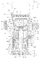
- the electric trimmer 10 includes a trimmer main body 20, a base 60, a battery 58 as a battery, a fixing mechanism 70, a holding mechanism 80, an elevating mechanism 90 as a position changing mechanism, and a controller 100. ing.
- a controller 100 e.g., a controller for controlling the electric trimmer 10 to control the electric trimmer 10.
- the trimmer main body 20 includes a housing 22, a motor 34 as a prime mover, a trigger 42 as an operation unit, a speed setting dial 46, and a state switching unit.
- the lock button 50 and the like are included in the configuration.
- the housing 22 constitutes the outer shell of the trimmer main body 20.
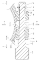
- the housing 22 has a double structure. Specifically, the housing 22 includes an inner case 24 that constitutes an inner peripheral side portion of the housing 22, and an outer case 30 that constitutes an outer peripheral side portion of the housing 22.
- the inner case 24 is made of resin.
- the inner case 24 is formed in a substantially bottomed cylindrical shape that is open downward.
- the inner case 24 includes an upper case portion 28 as an overhanging portion constituting the upper end portion of the inner case 24, and a cylindrical inner cylinder portion 26 extending downward from the upper case portion 28. , Is included.
- the upper case portion 28 is formed in a substantially rectangular shape when viewed from the lower side, and is projected from the inner cylinder portion 26 to one side in the first direction (the side in the direction of arrow C in FIGS. 4 and 7 (A)). ing.
- the inner case 24 is divided into two in the second direction.
- the inner case 24 includes a first inner case 24A constituting a portion of the inner case 24 on one side in the second direction (the side in the direction of arrow E in FIGS. 5 to 7) and the other side of the inner case 24 in the second direction (the other side in the second direction). It is configured to include a second inner case 24B constituting a portion (on the F direction side of the arrow in FIGS. 5 to 7). Then, in a state where the opening of the first inner case 24A and the opening of the second inner case 24B are abutted against each other, both are fastened and fixed.
- the inner cylinder portion 26 includes a pair of large diameter portions 26A constituting the upper end portion and the lower end portion of the inner cylinder portion 26, and a small diameter portion 26B constituting the vertical intermediate portion of the inner cylinder portion 26.
- the diameter of the small diameter portion 26B is set to be smaller than the diameter of the large diameter portion 26A.
- an inner cylinder diameter-expanded portion 26C that is raised one step outward in the radial direction is formed.
- the inner cylinder enlarged diameter portion 26C is formed with a pair of enlarged diameter protruding portions 26D protruding downward on one side and the other side in the first direction.
- the lower end portion of the inner cylinder enlarged diameter portion 26C is formed in an uneven shape when viewed from the radial outside of the inner cylinder portion 26.
- a trigger mounting portion 26E for mounting a trigger 42 is formed on the enlarged diameter protruding portion 26D on one side in the first direction, and the trigger mounting portion 26E is one in the first direction with respect to the enlarged diameter protruding portion 26D. It protrudes to the side.
- a button mounting portion 26F for mounting the lock button 50 is formed on the enlarged diameter protruding portion 26D on the other side in the first direction, and the button mounting portion 26F has a diameter with respect to the enlarged diameter protruding portion 26D. It goes down one step inward in the direction.
- An upper communication hole 26G (see FIGS. 3 and 7 (A)) is formed through the upper large-diameter portion 26A as a communication portion in one side and the other side in the second direction. Specifically, the upper communication hole 26G is arranged between the pair of enlarged diameter protrusions 26D. The upper communication hole 26G is formed in a rectangular shape when viewed from the radial outside of the inner cylinder portion 26, and the opening of the upper communication hole 26G is opened downward. Further, at the boundary portion between the lower large diameter portion 26A and the small diameter portion 26B, three lower communication holes 26H (FIGS. 3, FIGS. 5, and 7) are formed on one side and the other side in the second direction. (See (A)) are formed through each.
- the inner cylinder portion 26 is formed with six lower communication holes 26H.
- the lower communication hole 26H is formed in a long hole shape extending in the circumferential direction of the inner cylinder portion 26, and is arranged side by side in the circumferential direction of the inner cylinder portion 26.
- the lower communication hole 26H is a communication portion in the present invention.
- a plurality of (four locations in the present embodiment) contact portions 26J are formed on the outer peripheral portions of the pair of large diameter portions 26A, respectively. That is, in the present embodiment, eight contact portions 26J are formed on the inner cylinder portion 26.
- the contact portion 26J is formed in a substantially rectangular shape with the vertical direction as the longitudinal direction when viewed from the radial outside of the inner cylinder portion 26, and slightly protrudes outward in the radial direction with respect to the large diameter portion 26A. Further, the contact portions 26J are arranged at equal intervals in the circumferential direction of the inner cylinder portion 26.
- a protrusion 26K protruding outward in the radial direction is formed at the opening of the upper communication hole 26G on one side in the second direction.
- a bearing holding portion 26L for holding the second bearing 36L, which will be described later, is formed at the lower end portion of the inner cylinder portion 26, and the bearing holding portion 26L has a substantially annular plate shape with the vertical direction as the plate thickness direction. It is formed in the above direction and extends inward in the radial direction from the lower end portion of the inner cylinder portion 26.
- the bearing holding portion 26L is formed with a plurality of (five locations in the present embodiment) inner exhaust ports 26M on one side and the other side in the second direction, respectively. Specifically, three inner exhaust ports 26M are formed on one side portion of the bearing holding portion 26L in the second direction, and two inner exhaust ports 26M are formed on the other side portion of the bearing holding portion 26L in the second direction. It is formed.
- the inner exhaust port 26M is formed in a long hole shape extending in the circumferential direction of the inner cylinder portion 26, and is arranged side by side in the circumferential direction of the inner cylinder portion 26. Further, the bearing holding portion 26L is formed with a plurality of (four locations in the present embodiment) fixing bosses 26N for fixing the outer case 30, which will be described later.
- the fixed bosses 26N are formed in a cylindrical shape with the vertical direction as the axial direction, and are arranged at equal intervals in the circumferential direction of the inner cylinder portion 26 and between the inner exhaust ports 26M.
- the fixing boss 26N for fixing the outer case 30, which will be described later is arranged radially inside the outer peripheral surface of the inner cylinder portion 26.
- the fixed boss 26N is a fixed portion in the present invention.
- the upper case portion 28 is formed with a battery mounting portion 28A as a battery attachment / detachment portion for mounting the battery 58 described later, and the battery mounting portion 28A is formed in a concave shape open to the upper side and the other side in the first direction. Has been done. Further, the upper case portion 28 is provided with a connector 32 (see FIGS. 3 and 4), and the connector 32 is exposed in the battery mounting portion 28A.
- An intake port 28B (see FIGS. 2 and 3) is formed through the side walls on both sides of the upper case portion 28 in the second direction at the lower end side, and the intake port 28B has the first direction as the longitudinal direction. It is formed in the shape of a long hole. That is, the intake port 28B is arranged above the upper communication hole 26G of the inner case 24.
- the outer case 30 is made of metal and is composed of a single member that cannot be disassembled.
- the outer case 30 is formed in a substantially bottomed cylindrical shape that is open upward with the vertical direction as the axial direction.
- the outer case 30 includes a cylindrical outer cylinder portion 30A and a case bottom portion 30B constituting the lower end portion of the outer case 30.
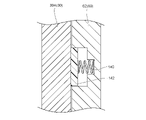
- the outer cylinder portion 30A is extrapolated to the inner cylinder portion 26 of the inner case 24, and the inner cylinder portion 26 and the outer cylinder portion 30A constitute the cylinder portion 22A of the housing 22.
- the extrapolation here represents a state in which the outer peripheral portion of the target is inserted inward, and represents a state in which the inner cylinder portion 26 is inserted inside the outer cylinder portion 30A.
- An insertion portion 30C is formed through the central portion of the case bottom portion 30B. Further, in the case bottom 30B, five outer exhaust ports 30D are formed through at positions corresponding to the inner exhaust port 26M of the inner case 24, and the outer exhaust port 30D corresponds to the inner exhaust port 26M. ,
- the outer cylinder portion 30A is formed in a long hole shape with the circumferential direction as the longitudinal direction. As a result, the inside and the outside of the inner case 24 are communicated with each other by the inner exhaust port 26M and the outer exhaust port 30D. Further, four fixing holes 30E (see FIG. 5) are formed through the case bottom 30B at positions corresponding to the fixing boss 26N of the inner case 24.
- the fixing bolt BL (in a broad sense, an element grasped as a fixing member) is inserted into the fixing hole 30E from the lower side and screwed into the fixing boss 26N, whereby the outer case 30 becomes an inner case. It is fixed to 24.
- a case cutting portion 30F as a pair of recesses is formed at a position corresponding to the enlarged diameter protruding portion 26D of the inner case 24, and the case cutting portion 30F is opened upward. It is formed in a concave shape and is also formed in a trapezoidal shape when viewed from the radial outside of the outer case 30.
- the upper end portion of the outer case 30 is arranged below the inner cylinder diameter expansion portion 26C of the inner case 24, and the outer cylinder portion 30A is inside the inner case 24.
- the portion of the cylinder portion 26 excluding the inner cylinder diameter expansion portion 26C is covered from the outside in the radial direction. That is, the upper communication hole 26G is invisiblely covered by the upper end portion of the outer case 30.
- the inner peripheral surface of the outer cylinder portion 30A is in contact with the contact portion 26J of the inner case 24.
- a gap 22B (see FIGS. 3 and 4) is formed in the tubular portion 22A between the small diameter portion 26B and the outer case 30.
- the gap 22B is formed over the entire circumference of the tubular portion 22A in the circumferential direction, the upper end portion of the gap 22B communicates with the inside of the inner case 24 by the upper communication hole 26G, and the lower end portion of the gap 22B is formed.
- the lower communication hole 26H communicates with the inside of the inner case 24.
- the diameter of the outer cylinder portion 30A is set so that the outer peripheral surface of the outer cylinder portion 30A is flush with the outer peripheral surface of the inner cylinder enlarged diameter portion 26C of the inner case 24.
- An engaging groove 30G (see FIG. 3) as a groove is formed on the inner peripheral surface of the upper end of the outer cylinder 30A at a position corresponding to the protrusion 26K of the inner case 24, and the engaging groove 30G is formed. , It is extended in the vertical direction and is open to the upper side.
- the protrusion 26K is inserted into the engaging groove 30G, and the protrusion 26K and the engaging groove 30G engage with each other in the circumferential direction of the inner case 24. It has become.
- the first rack 92 and the second rack 94 as a pair of racks constituting the elevating mechanism 90 described later are formed on the outer peripheral portion of the outer cylinder portion 30A. ing.
- the first rack 92 is formed on one side portion in the second direction of the outer cylinder portion 30A
- the second rack 94 is formed on the other side portion in the second direction of the outer cylinder portion 30A
- the first rack 92 and the first rack 92 are formed.
- the two racks 94 are extended in the vertical direction. That is, the first rack 92 and the second rack 94 are arranged 180 degrees apart in the circumferential direction of the outer cylinder portion 30A.
- the first rack 92 has a plurality of rack grooves 92A, and the rack grooves 92A extend in the circumferential direction of the outer cylinder portion 30A and are open to the outside in the radial direction of the outer cylinder portion 30A. Further, a plurality of rack grooves 92A are arranged side by side at equal intervals in the vertical direction. The portion between the rack grooves 92A adjacent to the top and bottom is configured as the rack teeth 92B. As a result, in the first rack 92, a plurality of rack teeth 92B are arranged side by side at equal intervals in the vertical direction.
- the second rack 94 is configured in the same manner as the first rack 92. That is, the second rack 94 has a plurality of rack grooves 94A arranged in the vertical direction. Further, in the second rack 94, a portion between the vertically adjacent rack grooves 94A is configured as a rack tooth 94B, and a plurality of rack teeth 94B are arranged side by side at equal intervals in the vertical direction.
- the motor 34 is configured as a brushless motor.
- the motor 34 is arranged coaxially with the inner cylinder portion 26 in the inner cylinder portion 26 of the inner case 24 and below the intake port 28B and the upper communication hole 26G, and is fixed to the inner cylinder portion 26.
- the upper end portion of the output shaft 34A of the motor 34 is rotatably supported by the first bearing 36U provided in the inner cylinder portion 26.
- the lower end portion of the output shaft 34A is rotatably supported by the second bearing 36L as a bearing, and the second bearing 36L is held by the bearing holding portion 26L of the inner cylinder portion 26.
- the lower end portion (tip portion) of the output shaft 34A projects downward from the lower end portion of the housing 22, and the collect chuck 38 is provided at the lower end portion of the output shaft 34A.
- the tip tool T is detachably fixed to the lower end of the output shaft 34A by the collect chuck 38.
- the motor 34 is electrically connected to the control unit 101 described later, and the motor 34 is driven by the control unit 101. As a result, the machined material is cut by the tip tool T that rotates together with the output shaft 34A.
- the collect chuck 38 corresponds to the tool holding portion of the present invention.
- a fan 40 is integrally rotatable on the output shaft 34A of the motor 34 on the upper side of the second bearing 36L.
- the fan 40 is configured as a so-called axial fan, and is configured to generate an downward air flow in the inner case 24.
- the cooling air AR flows into the inner case 24 from the intake port 28B and is discharged to the outside of the housing 22 from the inner exhaust port 26M of the inner case 24 and the outer exhaust port 30D of the outer case 30. It has become.
- the trigger 42 is configured as an operation unit for driving or stopping the motor 34.
- the trigger 42 is attached to the trigger mounting portion 26E of the inner case 24 and is operably exposed to one side in the first direction. Further, the upper end portion of the trigger 42 is rotatably supported by the inner case 24 with the second direction as the axial direction.
- the trigger 42 has an initial position (a position shown by a solid line in FIG. 4) and an operation position rotated counterclockwise from the initial position when viewed from one side in the second direction (at a two-dot chain line in FIG. 4). It is configured so that it can be rotated between (the position shown) and.
- the trigger 42 is urged to the initial position side by an urging spring (not shown), and the trigger 42 is held at the initial position in the non-operation state of the trigger 42.
- a micro switch 44 as a switch is provided on the other side of the trigger 42 in the first direction, and the micro switch 44 is electrically connected to a control unit 101 described later. Then, when the trigger 42 is operated from the initial position to the operation position, the lower end portion of the trigger 42 presses the micro switch 44, and the micro switch 44 outputs the detection signal to the control unit 101.
- the speed setting dial 46 is configured as a dial for changing the rotation speed of the motor 34.
- the speed setting dial 46 is formed in a substantially disk shape with the vertical direction as the plate thickness direction, and the inner case 24 has the vertical direction as the axial direction in the other side portion of the upper case portion 28 of the inner case 24 in the first direction. It is rotatably supported. Further, the speed setting dial 46 is operably exposed from the upper case portion 28 to the other side in the first direction.
- An encoder 48 for detecting the rotation position of the speed setting dial 46 is provided on the upper side of the speed setting dial 46, and the encoder 48 is electrically connected to the control unit 101. Then, by rotating the speed setting dial 46, the detection signal corresponding to the rotation position of the speed setting dial 46 is output from the encoder 48 to the control unit 101.
- the lock button 50 is provided on the button mounting portion 26F of the inner case 24 and is exposed from the button mounting portion 26F to the other side in the first direction.
- the lock button 50 is formed in a substantially rectangular shape when viewed from the other side in the first direction, and is made of an elastic member.
- a button board 52 is adjacent to one side of the lock button 50 in the first direction, and a tact switch 54 is mounted on the button board 52.
- the tact switch 54 is electrically connected to the control unit 101 described later. Then, when the lock button 50 is pressed, the tact switch 54 is configured to output a detection signal to the control unit 101.
- the lock button 50 is configured as a button for prohibiting or permitting driving to the motor 34 when the battery 58 is connected to the connector 32 of the housing 22.
- the lock button 50 is also configured as a button for continuing or stopping the driving of the motor 34 while the motor 34 is being driven.
- the base 60 is made of metal and is formed in a substantially bottomed cylinder shape that is open to the upper side. Specifically, the base 60 includes a base cylinder portion 62 as an extrapolation portion and a plate portion 64 constituting a lower end portion of the base 60.
- the base cylinder portion 62 is formed in a substantially cylindrical shape with the vertical direction as the axial direction, and a part of the base cylinder portion 62 in the circumferential direction is open. That is, a slit 62A extending in the vertical direction is formed in the base cylinder portion 62, and the slit 62A penetrates in the vertical direction and the radial direction of the base cylinder portion 62.
- the width dimension of the slit 62A is set to be larger than the width dimension of the first rack 92 and the second rack 94. Then, the base cylinder portion 62 (base 60) is extrapolated from the lower side to the cylinder portion 22A of the housing 22, and is fixed to the cylinder portion 22A by a fixing mechanism 70 described later.
- the first rack 92 or the second rack 94 is arranged inside the slit 62A when viewed from the radial outside of the base cylinder portion 62.
- the tubular portion 22A and the base tubular portion 62 of the housing 22 are configured as gripping portions to be gripped by an operator.
- an opening 62B is formed in a portion on one side in the second direction, and the opening 62B has a concave shape that is open downward when viewed from one side in the second direction. It is formed.
- the lower end of the slit 62A is communicated with the opening 62B.
- a first clamp portion (first chuck portion) 62C is provided at one end in the circumferential direction of the base cylinder portion 62, and a second clamp portion 62D is provided at the other end in the circumferential direction of the base cylinder portion 62. It is provided.
- the first clamp portion 62C and the second clamp portion (second chuck portion) 62D are formed in a substantially long block shape with the vertical direction as the longitudinal direction, and extend downward while projecting to one side in the second direction. ing.
- the first clamp portion (first chuck portion) 62C and the second clamp portion (second chuck portion) 62D correspond to the clamp portion or the chuck portion in the present invention.
- the clamp portion (chuck portion) is a part of the base 60 that protrudes radially outward from the base cylinder portion 62 and extends in the axial direction.
- the plate portion 64 is formed in a substantially rectangular plate shape with the vertical direction as the plate thickness direction, and is connected to the lower end portion of the base cylinder portion 62.
- a base insertion portion 64A (see FIGS. 3 and 4) for inserting the output shaft 34A and the tip tool T is formed through the substantially central portion of the plate portion 64.
- the lower surface of the plate portion 64 is configured as an abutting surface that comes into contact with the processed material during processing into the processed material.
- a bevel base 66 is provided on the lower side of the plate portion 64, and the bevel base 66 is formed in a substantially rectangular plate shape with the vertical direction as the plate thickness direction. Then, the bevel base 66 is fixed to the plate portion 64 by a fixing member such as a screw. Similar to the plate portion 64, the bevel base 66 is formed through the bevel insertion portion 66A (see FIGS. 3 and 4) for inserting the tool T.
- the battery 58 is formed in a substantially rectangular parallelepiped. Then, the battery 58 is mounted on the battery mounting portion 28A of the housing 22 from the other side in the first direction.
- the battery 58 has a connector (not shown), and when the battery 58 is attached to the battery mounting portion 28A, the connector is connected to the connector 32 and power is supplied from the battery 58 to the control unit 101. It has become.
- the battery 58 has a pair of lock members 58A, and the lock members 58A are provided on one side and the other side of the battery 58 in the second direction. When the battery 58 is mounted on the battery mounting portion 28A, the lock member 58A engages with the upper case portion 28 of the housing 22, and the movement of the battery 58 to the other side in the first direction is restricted.
- the fixing mechanism 70 is provided on the base 60 and is operated to fix the base 60 to the housing 22. It is configured as a mechanism for switching to a fixed state or a release state in which the base 60 is released from being fixed to the housing 22.
- the fixing mechanism 70 includes a pair of upper and lower fixed shafts 71 and a clamp lever 75.
- the fixed shaft 71 is formed in a substantially columnar shape with the first direction as the axial direction, and can move relative to the upper end portion and the lower end portion of the first clamp portion 62C and the second clamp portion 62D of the base 60 in the first direction. It is hung on.
- One end of the fixed shaft 71 protrudes from the first clamp portion 62C to one side in the first direction, and a male screw is formed at one end of the fixed shaft 71.
- the fixing nut 72 is screwed into one end of the fixed shaft 71 and is arranged on one side of the first clamp portion 62C in the first direction.
- a first fixed washer 73 (engaged washer 73) is attached to one end of the fixed shaft 71, and the first fixed washer 73 is arranged between the fixing nut 72 and the first clamp portion 62C. ing.
- one end of the fixed shaft 71 and the first clamp portion 62C are engaged with each other, and the movement of the fixed shaft 71 to the other side in the axial direction is restricted.
- the other end of the fixed shaft 71 projects from the second clamp portion 62D to the other side in the first direction.
- a connecting groove 71A (see FIG. 8) is formed at the other end of the fixed shaft 71, and the connecting groove 71A is opened to the other side in the first direction and penetrates in the second direction. Further, the groove depth of the connecting groove 71A is set so that the bottom portion of the connecting groove 71A is arranged inside the second clamp portion 62D.
- a second fixed washer 74 (fixed washer 74) as a fixing force applying portion is mounted on the other end of the fixed shaft 71, and the second fixed washer 74 is the other side of the second clamp portion 62D in the first direction. It is placed adjacent to the side. That is, the pair of second fixed washers 74 are arranged apart from each other in the vertical direction, and are arranged adjacent to the other side in the first direction of both ends in the longitudinal direction of the second clamp portion 62D.
- the second fixed washer 74 is formed in an annular shape and has both ends of the washer contact portion 74A connected to the washer contact portion 74A (see FIG. 10) as a contact portion extending in the second direction. It is configured to include a washer pressing portion 74B (see FIG.
- the washer contact portion 74A is arranged inside the connecting groove 71A, and the washer pressing portion 74B is extrapolated to the other end of the fixed shaft 71.
- the first fixed washer 73 (engaged washer 73) and the second fixed washer 74 correspond to the rigid member of the present invention.
- the clamp lever 75 is formed in a substantially Y-shaped plate shape with the second direction as the plate thickness direction and open to the other side of the first direction when viewed from the second direction, and the first clamp portion 62C and the second clamp portion. It is arranged on one side of the second direction of 62D. Further, the clamp lever 75 is inclined toward the other side in the second direction as it is directed toward the other side in the first direction when viewed from above, and is curved in a substantially arc shape (see FIG. 9). A bent portion 75A bent toward the other side in the second direction is formed at the upper end portion and the lower end portion of the clamp lever 75. A cam portion 75B (see FIG.
- the cam portion 75B is inserted into the connecting groove 71A of the fixed shaft 71, is provided on the fixed shaft 71, and is rotatably supported by the fixed pin 76 having the vertical direction as the axial direction.
- the clamp lever 75 is rotated from the fixed position (position shown in FIG. 9) and the release position (position shown in FIG. 12) rotated from the fixed shaft 71 to one side in the rotation direction (arrow G direction side in FIG. 9). It is configured so that it can be rotated between and.
- the outer peripheral portion of the cam portion 75B is configured as a cam surface 75C, and the cam surface 75C is formed in a substantially arc shape centered on the fixing pin 76 when viewed from above. More specifically, the radius of the cam surface 75C from the fixing pin 76 increases toward one side in the rotation direction of the clamp lever 75.
- the cam surface 75C abuts on the washer contact portion 74A of the second fixed washer 74 and presses the washer contact portion 74A to one side in the first direction. ..
- the cam surface 75C is arranged apart from the other side of the washer contact portion 74A in the first direction so that the cam surface 75C is released from the washer contact portion 74A. It has become.
- the clamp lever 75 is rotated from the release position to the fixed position, and the second clamp portion 62D is moved to the second clamp portion 62D by the pressing force of the cam portion 75B on the second clamp portion 62D via the second fixed washer 74.
- the base cylinder portion 62 is configured to be deformed so as to be displaced toward the clamp portion 62C.
- a clamping force is generated in which the base cylinder portion 62 tightens the cylinder portion 22A of the housing 22, and the base 60 is fixed to the housing 22 (outer cylinder portion 30A) by the clamping force.
- this state is referred to as a fixed state
- the clamping force of the base cylinder portion 62 is released, and the fixed state of the base 60 to the housing 22 is released (hereinafter, this state is referred to as a fixed state).
- this state is referred to as a release state).
- the portion of the outer cylinder portion 30A that receives the clamping force is the region where the base 60 can be mounted, and functions as the mounting surface of the base 60.
- a lever cap 77 is provided at the tip end portion (one side end portion in the first direction) of the clamp lever 75, and the tip end portion of the clamp lever 75 is covered with the lever cap 77.
- the tip of the clamp lever 75 is configured as a lever operating portion of the clamp lever 75, and an operator grips the lever cap 77 to rotate the clamp lever 75.
- the holding mechanism 80 is configured as a mechanism for holding the base 60 in the temporarily fixed state in the housing 22 in the released state of the fixing mechanism 70.
- the temporarily fixed state in the present embodiment means that the base 60 does not fall with respect to the cylinder portion 22A of the housing 22 due to its own weight, and the base 60 is in the cylinder portion 22A when the elevating mechanism 90 described later is manually operated.
- the holding mechanism 80 includes a connecting shaft 81 and a holding spring 85 as an urging member.
- the connecting shaft 81 is formed in a substantially stepped shaft shape with the first direction as the axial direction. Specifically, one end of the connecting shaft 81 is formed with a stopper portion 81A that is raised one step outward in the radial direction and an operation knob 81B that is raised one step outward in the radial direction from the stopper portion 81A. The knob 81B is arranged on one side in the first direction with respect to the stopper portion 81A. Then, with the operation knob 81B and the stopper portion 81A protruding from the first clamp portion 62C of the base 60 to one side in the first direction, the connecting shaft 81 moves in the vertical direction of the first clamp portion 62C and the second clamp portion 62D.
- a first holding washer 82 is inserted into the connecting shaft 81 from the other end side, and the first holding washer 82 is arranged between the stopper portion 81A and the first clamp portion 62C. Then, the stopper portion 81A engages with the first clamp portion 62C via the first holding washer 82, and the movement of the connecting shaft 81 to the other side in the axial direction is restricted.
- the other end of the connecting shaft 81 projects from the second clamp portion 62D to the other side in the first direction, and a male screw is formed on the outer peripheral portion of the other end of the connecting shaft 81.
- An adjusting nut 83 as a locking portion is screwed into the other end of the connecting shaft 81.
- a second holding washer 84 is attached to the other end of the connecting shaft 81, and the second holding washer 84 is arranged adjacent to one side of the adjusting nut 83 in the first direction.
- the holding spring 85 is configured as a compression coil spring and is mounted on the other end side portion of the connecting shaft 81. Specifically, one end of the holding spring 85 is locked to the second clamp portion 62D, and the other end of the holding spring 85 is locked to the adjusting nut 83 via the second holding washer 84. The holding spring 85 urges the second clamp portion 62D to one side in the first direction and urges the other end portion of the connecting shaft 81 to the other side in the first direction.
- the first clamp portion 62C and the second clamp portion 62D are displaced in the direction of approaching each other due to the urging force of the holding spring 85, and the cylinder portion 22A of the housing 22 is displaced in the base cylinder portion 62.
- a clamping force that tightens the spring is generated.
- a frictional force is generated between the base 60 and the housing 22 by the clamping force, and the urging force of the holding spring 85 is set so that the base 60 does not fall by its own weight due to the frictional force.
- the elevating mechanism 90 which will be described later, is activated, the inner peripheral surface of the base cylinder portion 62 of the base 60 slides on the outer peripheral surface of the outer cylinder portion 30A of the outer case 30, and the base 60 moves with respect to the housing 22. It is configured to move relative to the vertical direction.
- the second clamp portion 62D is formed with a concave spring accommodating portion 62E (see FIG. 11) opened on the other side in the first direction, and a part of the holding spring 85 is accommodated in the spring accommodating portion 62E. Has been done. Further, since the adjusting nut 83 moves relative to the axial direction of the connecting shaft 81 by rotating the adjusting nut 83 described above, the urging force of the holding spring 85 can be adjusted by the adjusting nut 83.
- the elevating mechanism 90 is a connecting shaft between the first rack 92 and the second rack 94 formed in the housing 22 described above and the holding mechanism 80 described above. It is configured to include 81 and a pinion 96. That is, the connecting shaft 81 is configured as a component of both the holding mechanism 80 and the elevating mechanism 90.
- the pinion 96 is formed in a substantially cylindrical shape with the first direction as the axial direction, is integrally rotatably fixed to the axial intermediate portion of the connecting shaft 81, and is arranged coaxially with the connecting shaft 81.
- the connecting shaft 81 and the pinion 96 may be integrally formed to form one member.
- the width length of each of the first rack 92 and the second rack 94 along the circumferential direction of the tubular portion 22A of the housing 22 is set to be slightly larger than the width length (length in the axial direction) of the pinion 96. ing.
- a plurality of pinion teeth 96A are formed on the outer peripheral portion of the pinion 96, and the plurality of pinion teeth 96A are formed over the entire circumference of the pinion 96 in the circumferential direction. Then, the pinion 96 is arranged between the first clamp portion 62C and the second clamp portion 62D of the base 60, and the pinion teeth 96A are placed in the rack groove 92A of the first rack 92 of the housing 22 or the second rack. It is arranged in the rack groove 94A of 94 and is configured to be meshed with the rack tooth 92B or the rack tooth 94B (in the example shown in FIG. 3, the pinion tooth 96A is meshed with the rack tooth 92B).
- the pinion 96 rotates relative to the first rack 92 (second rack 94), and the base 60 becomes the housing. It is configured to move up and down with respect to 22. Further, the pinion teeth 96A are arranged in the rack groove 92A (rack groove 94A). Therefore, when the base 60 moves up and down with respect to the housing 22, the pinion teeth 96A engage with both ends in the longitudinal direction of the rack groove 92A (rack groove 94A), so that the relative rotation of the base 60 with respect to the housing 22 is restricted. It is configured to be. Then, after adjusting the elevating position of the base 60, the fixing mechanism 70 is changed from the released state to the fixed state, so that the base 60 is fixed at the adjusted position.
- the controller 100 is housed inside the upper case portion 28 of the housing 22 and is fixed to the upper case portion 28.
- the controller 100 has a control unit 101 and an inverter unit 110.
- the connector 32, the motor 34, the micro switch 44, the encoder 48, and the tact switch 54 described above are electrically connected to the controller 100.
- the control unit 101 is configured to control the operation of the motor 34 in response to the operation of the trigger 42 and the lock button 50. Further, the control unit 101 is configured to control the rotation speed of the motor 34 according to the rotation position of the speed setting dial 46.
- the controller 100 has a control circuit board (not shown), and the control unit 101 and the inverter unit 110 are mounted on the control circuit board.
- the control unit 101 has a calculation unit 102, and the calculation unit 102 performs various controls such as drive control of the inverter unit 110.
- the arithmetic unit 102 is a microcomputer.
- the inverter unit 110 is a circuit in which switching elements 110a (six in this embodiment) are bridge-connected.
- the detection resistor 120 is provided in the path of the drive current of the brushless motor as the motor 34.
- the control circuit voltage supply circuit 130 converts the voltage of the battery 58 into a voltage suitable for the operation of the control unit 101 and supplies the voltage to the control unit 101.
- the magnetic sensor 107 is, for example, a Hall element, and outputs a signal corresponding to the rotational position of the brushless motor as the motor 34.
- the motor current detection circuit 103 detects the drive current of the brushless motor as the motor 34 by the terminal voltage of the detection resistor 120.
- the switch operation detection circuit 104 detects the operation of the trigger 42 as an operation unit by the operator.
- the rotor position detection circuit 105 detects the rotational position of the brushless motor as the motor 34 based on the signal from the magnetic sensor 107.
- the motor rotation speed detection circuit 106 detects the rotation speed of the brushless motor as the motor 34 based on the signal from the rotor position detection circuit 105.
- the calculation unit 102 calculates the rotation speed of the brushless motor as the motor 34 based on the detection result of the rotor position detection circuit 105, and outputs the rotation speed to the control signal output circuit 108.
- the control unit 101 when the tact switch 54 (lock button 50) as the state switching unit is operated when the brushless motor as the motor 34 is in the non-driving state, the brushless motor as the motor 34 is in the driving state. Occasionally, the control state to be changed differs depending on whether the tact switch 54 (lock button 50) as the state switching unit is operated. For example, when the brushless motor as the motor 34 is in the drive state, the control unit 101 is in an on-lock state in which the drive of the brushless motor as the motor 34 is maintained even if the operation on the trigger 42 as the operation unit is released.
- the control state has an on-lock release state in which the drive of the brushless motor as the motor 34 is stopped by releasing the operation of the trigger 42 as the operation unit, and the tact switch 54 (lock button 50) as the state switching unit is released. It can be exemplified that control is performed so that the on-lock state and the on-lock release state can be switched based on the operation. Further, for example, it can be exemplified that the control unit 101 controls to release the on-lock state based on the operation of the trigger 42 as the operation unit in the on-lock state.
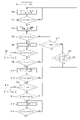
- step 1 the battery 58 is attached to the battery mounting portion 28A of the housing 22, and the battery 58 is connected to the connector 32. After connecting the battery 58 to the connector 32, the process proceeds to step 2 (S2).
- step 2 the control unit 101 is set to a state in which the driving of the motor 34 is prohibited (off-lock state). After the process of step 2, the process proceeds to step 3 (S3).
- step 3 the control unit 101 determines whether or not the lock button 50 has been pressed based on the output signal of the tact switch 54. In step 3, if the lock button 50 is not pressed (No in step 3), the process returns to step 2. That is, the off-lock state of the motor 34 is maintained. On the other hand, when the lock button 50 is pressed in step 3 (Yes in step 3), the process proceeds to step 4 (S4).
- step 4 the control unit 101 is set to a state in which driving of the motor 34 is permitted (an off-lock release state, which is also referred to as a drive standby state of the motor 34). Then, after the processing of step 4, the process proceeds to step 5 (S5).
- step 5 the control unit 101 determines whether or not the trigger 42 has been operated to the operation position based on the output signal of the micro switch 44. In step 5, when the trigger 42 is operated to the operation position (in the case of Yes in step 5), the process proceeds to step 6.
- step 6 the motor 34 is driven by the control unit 101.
- the output shaft 34A of the motor 34 rotates around its own shaft, and the operator cuts the machined material with the tip tool T.
- the control unit 101 rotates the output shaft 34A at a rotation speed corresponding to the rotation position of the speed setting dial 46.
- step 7 the process proceeds to step 7 (S7).
- step 7 the control unit 101 determines whether or not the operation of the trigger 42 to the operation position is continued based on the output signal of the micro switch 44. In step 7, when the operation of the trigger 42 to the operation position is not continued, that is, when the trigger 42 returns to the initial position (No in step 7), the process proceeds to step 8 (S8).
- step 8 the control unit 101 stops driving the motor 34. That is, when the operator releases the operation of the trigger 42, the driving of the motor 34 is stopped. Then, after the processing of step 8, the process returns to step 5.
- step 7 when the operation to the operation position of the trigger 42 is continued (in the case of Yes in step 7), the process proceeds to step 9 (S9).
- step 9 the control unit 101 determines whether or not the lock button 50 has been pressed based on the output signal from the tact switch 54. In step 9, if the lock button 50 is not pressed (No in step 9), the process returns to step 7. On the other hand, in step 9, when the lock button 50 is pressed (Yes in step 9), the process proceeds to step 10 (S10).
- step 10 the control unit 101 puts the motor 34 into a state of maintaining the drive (on-lock state). That is, when the lock button 50 is pressed while the trigger 42 is operated to the operation position, the state transitions to the on-lock state in which the driving of the motor 34 is maintained. After the process of step 10, the process proceeds to step 11 (S11).
- step 11 the control unit 101 determines whether or not the trigger 42 has returned to the initial position based on the output signal of the micro switch 44. If the trigger 42 has not returned to the initial position in step 11 (No in step 11), the process returns to step 10. That is, when the operation of the trigger 42 to the operation position by the operator is continued, the process returns to step 10 and the on-lock state is maintained.
- step 12 S12
- step 12 the control unit 101 determines whether or not the lock button 50 has been pressed based on the output signal of the tact switch 54.
- step 12 the process proceeds to step 13 (S13).
- step 13 the control unit 101 stops driving the motor 34. That is, when the lock button 50 is pressed in the on-lock state of the motor 34, the on-lock state of the motor 34 is released and the motor 34 is stopped. Then, after the processing of step 13, the process returns to step 5.
- step 14 the process proceeds to step 14 (S14).
- step 14 the control unit 101 determines whether or not the trigger 42 has been operated to the operation position based on the output signal of the micro switch 44. If the trigger 42 has not been operated to the operation position in step 14 (No in step 14), the process returns to step 12. That is, the on-lock state of the motor 34 is maintained. On the other hand, when the trigger 42 is operated to the operation position in step 14 (in the case of Yes in step 14), the process proceeds to step 15 (S15).
- step 15 the control unit 101 stops driving the motor 34. That is, when the lock button 50 is not pressed and the trigger 42 is operated to the operation position again in the on-lock state of the motor 34, the on-lock state of the motor 34 is released and the motor 34 is stopped. Then, after the processing of step 15, the process proceeds to step 16 (S16).
- step 16 the control unit 101 determines whether or not the trigger 42 has returned to the initial position based on the output signal of the micro switch 44. If the trigger 42 has not returned to the initial position in step 16 (No in step 16), the process returns to step 15. That is, the stopped state of the motor 34 is maintained. On the other hand, when the trigger 42 returns to the initial position in step 16 (in the case of Yes in step 16), the process returns to step 5. That is, when the operator's operation on the trigger 42 is released, the process returns to step 5 with the motor 34 stopped. As a result, the trigger 42 is operated to the operation position again, and the motor 34 is driven again by the control unit 101.
- step 5 if the trigger 42 is not operated to the operation position (No in step 5), the process proceeds to step 17 (S17).
- step 17 the control unit 101 determines whether or not the lock button 50 has been pressed based on the output signal from the tact switch 54. If the lock button 50 is pressed in step 17 (Yes in step 17), the process returns to step 2. That is, the control unit 101 shifts the motor 34 from the drive standby state to the off-lock state. On the other hand, if the lock button 50 is not pressed in step 17 (No in step 17), the process proceeds to step 18 (S18).
- step 18 the control unit 101 determines whether or not the lock button 50 has been pressed within a predetermined time (10 seconds in the present embodiment) based on the output signal from the tact switch 54. Further, in step 18, the control unit 101 determines whether or not the trigger 42 has been operated to the operation position within a predetermined time based on the output signal from the micro switch 44. That is, in step 18, the control unit 101 determines whether or not the operation for the lock button 50 or the trigger 42 has been operated within a predetermined time.
- step 18 if the operation for the lock button 50 or the trigger 42 is operated within a predetermined time (in the case of Yes in step 18), the process returns to step 5. That is, it returns to the drive standby state of the motor 34.
- step 18 if the operation for the lock button 50 or the trigger 42 is not operated within a predetermined time (No in step 18), the process returns to step 2. That is, when the lock button 50 or the trigger 42 is not operated in the drive standby state of the motor 34, the control unit 101 shifts the motor 34 from the drive standby state to the off-lock state.
- the housing 22 constituting the outer shell of the trimmer main body 20 includes an inner case 24 having a cylindrical inner cylinder portion 26 and an outer case 30 extrapolated to the inner case 24.
- the outer case 30 is fixed to the inner case 24. That is, the housing 22 has a double structure of the inner case 24 and the outer case 30. Therefore, the rigidity of the housing 22 can be increased.
- the outer case 30 is made of a single member that cannot be disassembled, and the base cylinder portion 62 of the base 60 is extrapolated and detachably attached to the outer case 30. That is, in the housing 22, the portion that directly supports the base cylinder portion 62 is composed of a single member that cannot be disassembled. Therefore, the support rigidity of the housing 22 with respect to the base cylinder portion 62 can be increased.
- a suitable fixing structure for the base 60 can be realized.
- the inner case 24 is made of resin
- the outer case 30 is made of metal. Therefore, in the tubular portion 22A of the housing 22, the weight of the tubular portion 22A can be reduced while increasing the strength of the portion that directly supports the base 60.
- the outer case 30 is formed in a substantially bottomed cylindrical shape that is open to the upper side, and the case bottom 30B of the outer case 30 is fastened and fixed to the fixing boss 26N of the inner case 24 by the fixing bolt BL. Further, a fixing bolt BL and a fixing boss 26N for fixing the outer case 30 to the inner case 24 are arranged radially inside the outer peripheral surface of the outer cylinder portion 30A. As a result, for example, the upper end portion of the outer case 30 is projected outward in the radial direction of the outer cylinder portion 30A in the same manner as the upper case portion 28 of the inner case 24, and the protruding portion is the upper case portion of the inner case 24.
- the physique of the outer case 30 can be reduced in size as compared with a configuration in which the outer case 30 is fastened and fixed (hereinafter, this configuration is referred to as an electric trimmer in a comparative example).
- this configuration is referred to as an electric trimmer in a comparative example.
- the weight of the outer case 30 can be reduced, and the weight of the electric trimmer 10 as a whole can be reduced.
- the upper case portion 28 can be miniaturized, and the physique of the electric trimmer 10 as a whole can be miniaturized.
- an upper case portion 28 is provided at the upper end portion of the inner case 24, and the upper case portion 28 projects from the outer peripheral surface of the outer case 30 (outer cylinder portion 30A) when viewed from the vertical direction. ..
- the controller 100 that drives and controls the motor 34 can be arranged in the upper case portion 28 having a relatively large cross-sectional area as compared with the inner cylinder portion 26.
- the battery mounting portion 28A can be provided in the upper case portion 28, and the battery 58 can be mounted in the inner case 24.
- the lower end side portion of the output shaft 34A is supported by the second bearing 36L, and the second bearing 36L is held by the bearing holding portion 26L of the inner case 24.
- a fixing boss 26N for fastening and fixing the outer case 30 is formed on the bearing holding portion 26L.
- the inner cylinder portion 26 of the inner case 24 is configured to include a small diameter portion 26B and a large diameter portion 26A having a larger diameter than the small diameter portion 26B.
- the inner peripheral surface of the outer case 30 externally inserted into the inner cylinder portion 26 is in contact with the large diameter portion 26A.
- the heat of the motor 34 operating in the inner cylinder portion 26 can be suppressed from being transferred to the outer case 30 by the gap 22B between the outer case 30 and the small diameter portion 26B.
- rattling of the outer case 30 in the extrapolated state of the outer case 30 to the inner case 24 can be suppressed. Therefore, it is possible to satisfactorily maintain the extrapolation state of the outer case 30 to the inner case 24 while suppressing the temperature rise of the outer case 30 that functions as the grip portion to be gripped by the operator.
- the large diameter portion 26A constitutes the upper end portion and the lower end portion of the inner cylinder portion 26, and the small diameter portion 26B constitutes the vertical intermediate portion of the inner cylinder portion 26. That is, the large diameter portion 26A is arranged on both sides of the inner cylinder portion 26 in the axial direction with respect to the small diameter portion 26B. Thereby, the outer case 30 can be supported by the axial end portion of the inner cylinder portion 26. Therefore, the extrapolation state of the outer case 30 to the inner case 24 can be maintained even better.
- a fan 40 that is rotated by driving a motor 34 is provided inside the inner case 24 .
- an upper communication hole 26G and a lower communication hole 26H are formed in the large diameter portion 26A, and the gap 22B and the inside of the inner case 24 communicate with each other by the upper communication hole 26G and the lower communication hole 26H.
- the cooling air AR flowing into the inner case 24 includes the cooling air AR1 flowing into the upper communication hole 26G and the cooling air AR2 flowing downward in the inner cylinder 26 at the upper end of the inner cylinder 26. It is divided into.
- the cooling air AR1 flows downward through the gap 22B between the small diameter portion 26B of the inner case 24 and the outer case 30, and flows into the lower end portion of the inner cylinder portion 26 from the lower communication hole 26H. Then, the cooling air AR1 and the cooling air AR2 merge at the lower end of the inner cylinder portion 26 and are discharged to the outside of the housing 22 from the inner exhaust port 26M and the outer exhaust port 30D. As described above, the motor 34 can be cooled by the cooling air AR2 while the outer case 30 is cooled by the cooling air AR1. Therefore, the outer case 30 and the motor 34 can be effectively cooled.
- a pair of case cutting portions 30F opened upward are formed at the upper end portion of the outer case 30.
- the trigger 42 provided in the inner case 24 is arranged in one case cutting portion 30F
- the lock button 50 provided in the inner case 24 is arranged in the other case cutting portion 30F. ..
- the outer case 30 can be extrapolated to the inner case 24 by aligning the positions of the case cutting portion 30F with the trigger 42 and the lock button 50.
- the orientation of the outer case 30 with respect to the inner case 24 in the circumferential direction can be aligned with the case cutting portion 30F, the trigger 42, and the lock button 50 as markers. .. Therefore, workability when extrapolating the outer case 30 to the inner case 24 can be improved.
- the inner cylinder portion 26 of the inner case 24 is formed with a protrusion 26K protruding outward in the radial direction, and the inner peripheral surface of the outer case 30 is extended in the vertical direction and opened upward.
- An engaging groove 30G is formed.
- the base 60 of the electric trimmer 10 is provided with a fixing mechanism 70 for switching between a fixed state in which the base 60 is fixed to the housing 22 and a release state in which the fixed state is released.
- the base 60 is provided with a holding mechanism 80, and the holding mechanism 80 holds the base 60 in the temporarily fixed state in the housing 22 in the released state of the fixing mechanism 70.
- the base 60 is held by the holding mechanism 80 so that the base 60 does not fall under its own weight in the released state of the fixing mechanism 70. That is, the holding mechanism 80 functions as a mechanism for assisting the fixing mechanism 70 in the released state of the fixing mechanism 70, and the holding mechanism 80 suppresses that the fixing force of the base 60 to the housing 22 immediately becomes zero. As a result, the operator does not need to support the base 60 in the released state of the fixing mechanism 70. Therefore, a suitable fixing structure for the base 60 can be realized.
- the holding mechanism 80 includes a connecting shaft 81 for connecting the first clamp portion 62C and the second clamp portion 62D of the base 60, and a holding spring 85.
- the connecting shaft 81 is bridged to the first clamp portion 62C and the second clamp portion 62D so as to be relatively movable in the axial direction, and one end of the connecting shaft 81 is engaged with the first clamp portion 62C.
- the movement of the connecting shaft 81 to the other side in the axial direction is restricted, the holding spring 85 is mounted on the other end side portion of the connecting shaft 81, and the second clamp portion 62D is attached to the connecting shaft 81.
- the connecting shaft 81 and the holding spring 85 press the first clamp portion 62C and the second clamp portion 62D inward in the axial direction of the connecting shaft 81, and the first clamp portion 62C and the second clamp portion 62D approach each other.
- the base cylinder portion 62 is deformed in the direction of the clamp.
- the holding mechanism 80 is omitted in the electric trimmer 10
- the pressing force of the holding spring 85 on the second clamp portion 62D is eliminated, so that the second clamp portion 62D of the base 60 in the released state (FIG.
- the second clamp portion 62D shown by the one-point difference line of 11 is attached to the second clamp portion 62D of the fixed base 60 (see the second clamp portion 62D shown by the two-point difference line of FIG. 11).
- it is largely displaced to the other side in the first direction.
- the pressing force of the holding spring 85 acts on the second clamp portion 62D, so that the second clamp portion 62D of the base 60 in the released state (in the solid line in FIG.
- the second clamp portion 62D shown in the above section is located on one side in the first direction as compared with the case where the holding mechanism 80 is omitted. Therefore, the base cylinder portion 62 tightens the cylinder portion 22A of the housing 22, and a clamping force for clamping the cylinder portion 22A is generated in the base 60. As a result, a frictional force is generated between the base cylinder portion 62 and the cylinder portion 22A, and the base 60 can be held in the temporary holding state by the frictional force.
- the temporary holding state here represents a state in which it is fixed to such an extent that it can be moved by hand while suppressing movement under its own weight.
- the adjusting nut 83 is screwed to the other end of the connecting shaft 81.
- the holding spring 85 is arranged between the second clamp portion 62D and the adjusting nut 83.
- the connecting shaft 81 is provided with a pinion 96 of the elevating mechanism 90 so as to be integrally rotatable, and the pinion 96 is meshed with the first rack 92 or the second rack 94 of the outer case 30.
- the base 60 can be raised and lowered with respect to the housing 22 by rotating the operation knob 81B of the connecting shaft 81 in the released state of the fixing mechanism 70. That is, the connecting shaft 81 can be configured as a common component of the holding mechanism 80 and the elevating mechanism 90.
- the connecting shaft 81 is not configured as a common component of the holding mechanism 80 and the elevating mechanism 90, the space of the holding mechanism 80 and the elevating mechanism 90 can be saved, and the driving machine 10 can be downsized. Can be planned.
- one end portion (stopper portion 81A) of the connecting shaft 81 engages with the first clamp portion 62C via the first holding washer 82, and the movement of the connecting shaft 81 to the other side in the axial direction is restricted.
- the holding spring 85 urges the other end of the connecting shaft 81 in the axial direction to the other side in the axial direction.
- a shaft holding force for limiting the rotation of the connecting shaft 81 is generated in the connecting shaft 81 by the urging force of the holding spring 85.
- the pinion 96 is rotatably provided on the connecting shaft 81 and is meshed with the first rack 92 or the second rack 94 of the outer case 30.
- the shaft holding force generated in the connecting shaft 81 can be applied to the meshing portion between the pinion 96 and the first rack 92 or the second rack 94. That is, the elevating mechanism 90 can also function as a mechanism for holding the base 60 in the temporarily fixed state to the housing 22. Therefore, the urging force of the holding spring 85 can be effectively utilized to hold the base 60 in the temporarily fixed state.
- first rack 92 and the second rack 94 of the elevating mechanism 90 are arranged apart from each other in the circumferential direction of the outer cylinder portion 30A. Therefore, the position of the base 60 when the pinion 96 is meshed with the first rack 92 in the circumferential direction of the tubular portion 22A (hereinafter, this position is referred to as the first position) and the pinion 96 are meshed with the second rack 94.
- the position of the base 60 (hereinafter, this position is referred to as a second position) when the base 60 is moved can be set to a different position. Therefore, the elevating mechanism 90 can be operated with the base 60 arranged at the first position or the second position according to the working mode of the operator. Therefore, the workability for the worker can be improved.
- a plurality of racks are formed in the outer cylinder portion 30A in the circumferential direction of the cylinder portion 22A of the housing 22.
- the width length of each of the first rack 92 and the second rack 94 along the circumferential direction of the tubular portion 22A is set to be larger than the width length of the pinion 96. Therefore, the total length of the rack along the circumferential direction of the tubular portion 22A (the total width and length of the first rack 92 and the second rack 94) is set to be more than twice the width and length of the pinion 96.
- the "total length of the rack along the circumferential direction of the cylinder portion" in the present invention means that a plurality of racks (first rack 92 and second rack 94) are formed on the outer cylinder portion 30A as in the present embodiment. If so, it means the total width and length of a plurality of racks (first rack 92 and second rack 94).
- the elevating mechanism 90 can be used by changing the position of the base 60 in the circumferential direction of the outer cylinder portion 30A.
- the motor 34 can be quickly turned on and off when working with one hand. Further, even if the gripping state is released during the operation of the trigger 42, the motor 34 is stopped, so that it is possible to suppress damage to the processed material. Further, since the motor 34 can be maintained on by operating the lock button 50, the work can be continued even if the operating force on the trigger 42 is released, and fatigue during work can be reduced. can. Further, since the off-lock control can be executed so that the motor 34 is not driven even if the trigger 42 is operated unless the lock button 50 is operated, it is assumed that a foreign object comes into contact with the trigger 42 during non-working.
- the motor 34 is not driven, and adverse effects such as wasteful energy consumption can be suppressed.
- the lock button 50 to release the off-lock state in the same way, the transition to the on-lock state can be performed, the number of parts of the control switch can be reduced, and the off-lock state can be changed to the on-lock state. It is possible to perform the transition of the above in the same gripping state.
- the transition from the off-lock release to the on-lock state can be performed by the operation with two fingers in the gripped state, the workability can be greatly improved.
- the fixing bolt BL is inserted into the fixing hole 30E of the outer case 30 from below and screwed into the fixing boss 26N of the inner case 24 so that the outer case 30 becomes the inner case 24. It is fastened and fixed. That is, the fixing bolt BL extends in the vertical direction.
- the fixing bolt BL may be arranged at the lower end of the tubular portion 22A so as to extend in the first direction or the second direction, and the inner case 24 and the outer case 30 may be fastened and fixed. ..
- a clamping force for clamping the tubular portion 22A of the housing 22 is generated in the base 60 to hold the base 60 in a temporarily fixed state in the housing 22, but the base 60 is held.
- the mechanism for holding the temporarily fixed state is not limited to this.
- a base is provided with a high friction member having a relatively high coefficient of friction on at least one of the outer peripheral surface of the outer cylinder portion 30A of the outer case 30 and the inner peripheral surface of the base cylinder portion 62 of the base 60.
- the base 60 may be temporarily fixed by the frictional force generated between the cylinder portion 62 and the outer cylinder portion 30A.
- the holding spring 85 is configured to be located on the outer periphery of the connecting shaft 81 so that the first clamp portion 62C and the second clamp portion 62D are close to each other, it may be provided on the fixed shaft 71, for example, the fixing pin 76 may be provided.
- a holding spring 85 may be interposed between the fixing pin 76 and the second fixed washer 74 while increasing the size in the axial direction so as to exert an urging force on the fixing pin 76 and the second fixed washer 74.
- a holding spring 140 and a pressing member 142 as urging members are provided on one of the outer cylinder portion 30A and the base cylinder portion 62, and the outer cylinder portion 30A and the base cylinder portion 62 are provided.
- a frictional force may be generated between the two and the base 60 to temporarily hold the base 60 in the temporarily fixed state (in the example shown in FIG. 15, the holding spring 140 and the pressing member 142 are provided on the base cylinder portion 62.
- the base cylinder portion 62 is formed with a recess opened to the outer cylinder portion 30A side, and the holding spring 140 and the pressing member 142 are arranged in the recess.
- the holding spring 140 is configured as a compression coil spring and presses the pressing member 142 toward the outer cylinder portion 30A. As a result, a frictional force is generated between the pressing member 142 and the outer cylinder portion 30A, and the base 60 can be held in the temporarily fixed state.
- the material of the pressing member 142 is not particularly specified, for example, by using an elastic member such as rubber, the holding force with respect to the base 60 can be further increased.
- first rack 92 and second rack 94 are formed in the outer cylinder portion 30A of the housing 22, but three or more racks are formed in the outer cylinder portion 30A.
- one rack may be formed on the outer cylinder portion 30A.
- the width length of the rack along the circumferential direction of the cylinder portion 22A is set to be at least twice the width length of the pinion 96.
- the width and length of the rack are set to 1/2 of the entire circumference of the outer cylinder portion 30A.
- the total length of the rack along the circumferential direction of the tubular portion 22A is set to be at least twice the width and length of the pinion 96. Therefore, even when one rack is formed on the outer cylinder portion 30A, the position of the base 60 in the circumferential direction of the outer cylinder portion 30A can be changed by the elevating mechanism 90.
- the first rack 92 and the second rack 94 are formed on the housing 22, and the pinion 96 is provided on the base 60.
- the pinion 96 is provided on the housing 22 and the base 60 is provided with a pinion 96. It may be configured to form one rack 92 and a second rack 94.
- the electric trimmer 10 configured as described above is provided with a fixing mechanism 70 for switching between a fixed state in which the base 60 is fixed to the housing 22 and a release state in which the fixed state is released.
- the fixing mechanism 70 includes a pair of upper and lower fixed shafts 71 spanning the first clamp portion 62C and the second clamp portion 62D of the base 60, and a pair of cam portions 75B connected to the other end of the fixed shaft 71. It is configured to include a pair of fixed washers (second fixed washers) 74 provided at the other end of the fixed shaft 71.
- one end of the fixed shaft 71 engages with the first clamp portion 62C via the fixing nut 72 and the first fixed washer 73 (engagement washer 73), and the fixed shaft 71 moves to the other side in the axial direction. Is restricted. Therefore, at the fixed position of the clamp lever 75, a pressing force (corresponding to the fixing force of the present invention) is applied from the second fixed washer 74 to the second clamp portion 62D. As a result, the second clamp portion 62D is displaced toward the first clamp portion 62C, and the base cylinder portion 62 is deformed. As a result, a clamping force for tightening the cylinder portion 22A of the housing 22 is generated in the base cylinder portion 62, and the base 60 is fixed to the housing 22 by the clamping force.
- the fixed shaft 71 is bridged to the upper end portion and the lower end portion of the first clamp portion 62C and the second clamp portion 62D of the base 60, respectively, and the cam portion 75B and the second fixed washer 74 are provided. It is provided on each of the pair of fixed shafts 71. Thereby, both ends in the longitudinal direction of the first clamp portion 62C and the second clamp portion 62D can be sandwiched by the fixing mechanism 70.
- the pressing force input from the second fixed washer 74 for deforming the base cylinder portion 62 to the second clamp portion 62D is the upper portion (upper end portion) of the second clamp portion 62D. And the lower part (lower end part), respectively.
- the base cylinder portion 62 can be deformed satisfactorily over the entire axial direction.
- the clamping force for clamping the cylinder portion 22A of the base cylinder portion 62 can be uniformly applied in the axial direction of the base cylinder portion 62 as compared with the electric trimmer of the comparative example. Therefore, the base 60 can be stably fixed to the housing 22.
- the pressing force acting on the upper portion and the lower portion of the second clamp portion 62D acts in the range of the upper portion 30% and the lower portion 30% in the extending range of the second clamp portion 62D, and therefore the second clamp portion 62D. It is possible to reduce the possibility that the fixing force of the upper and lower ends of the portion 62D is insufficient. Further, when the lower portion of the second clamp portion 62D is positioned below the lower end of the inner cylinder portion 26, the fixing force to the lower portion of the second clamp portion 62D may be insufficient, but the upper portion of the second clamp portion 62D. It is possible to cover the damping of the fixing force by the pressing force acting on.
- the pair of fixed shafts 71 generate a pressing force on the upper portion (upper end portion) and the lower portion (lower end portion) of the second clamp portion 62D.
- Means for generating pressing force may be provided in the upper part and the lower part of the clamp portion 62D.
- the fixing mechanism 70 has a clamp lever 75, and the clamp lever 75 has a pair of upper and lower cam portions 75B.
- the pair of cam portions 75B connected to the fixed shaft 71 are connected by the clamp lever 75.
- the pair of cam portions 75B can be operated at the same time by rotating the clamp lever 75. Therefore, even if the fixing mechanism 70 includes a pair of fixed shafts 71, a pair of second fixed washers 74, and a pair of cam portions 75B, the complexity of the operator when operating the fixing mechanism 70 is reduced. be able to.
- a connecting groove 71A opened to the other side in the axial direction is formed at the other end of the fixed shaft 71, and the cam portion 75B is arranged in the connecting groove 71A so as to be rotatable with the fixed shaft 71. It is connected.
- the connecting groove 71A is omitted, and a pair of cam portions 75B are arranged on both sides of the fixed shaft 71 in the vertical direction with respect to one fixed shaft 71, and the cam portion 75B and the fixed shaft 71 are arranged.
- the second fixed washer 74 includes a washer contact portion 74A extending in the second direction, a washer pressing portion 74B formed in an annular shape and having both ends in the longitudinal direction of the washer contact portion 74A connected to each other. Is configured to include.
- the washer contact portion 74A is inserted into the connecting groove 71A of the fixed shaft 71 so as to be able to contact the cam portion 75B.
- the washer pressing portion 74B is extrapolated to the fixed shaft 71 so that the second clamp portion 62D can be pressed.
- the pressing force of the cam portion 75B on the second fixed washer 74 is input to the central portion of the second fixed washer 74, and the input pressing force is uniformly transmitted in the circumferential direction of the washer pressing portion 74B, and the washer.
- the second clamp portion 62D can be pressed by the pressing portion 74B.
- the base cylinder portion 62 is provided with a connecting shaft 81 between a pair of upper and lower fixed shafts 71, and the connecting shaft 81 is provided with a pinion 96 constituting an elevating mechanism 90 so as to be integrally rotatable. And the pinion 96 meshes with the first rack 92 or the second rack 94 formed on the outer case 30.
- the elevating mechanism 90 for changing the position of the base 60 with respect to the housing 22 can be provided by effectively utilizing the area between the pair of upper and lower fixed shafts 71.
- Modification 1 of the fixing mechanism 70 is configured in the same manner as the fixing mechanism 70 of the present embodiment except for the following points. That is, in the first modification of the fixing mechanism 70, a pair of clamp levers 75 are provided corresponding to a pair of fixed shafts 71 (not shown in FIG. 16). The clamp lever 75 is formed in a substantially rectangular shape with the first direction as the longitudinal direction when viewed from one side in the second direction.
- the connecting groove 71A is omitted in the fixed shaft 71, and the cam portion 75B of the clamp lever 75 is arranged on the upper side and the lower side of the other end of the fixed shaft 71, respectively, and the fixing pin. It is rotatably connected to the fixed shaft 71 by the 76 with the vertical direction as the axial direction. Further, in the fixed washer 74, the washer contact portion 74A is omitted.
- the longitudinal direction of the first clamp portion 62C and the second clamp portion 62D of the base cylinder portion 62 is the same as in the present embodiment. Both ends can be sandwiched by the fixing mechanism 70.
- the clamping force for clamping the cylinder portion 22A of the base cylinder portion 62 can be uniformly applied in the axial direction of the base cylinder portion 62. Therefore, even in the first modification of the fixing mechanism 70, the base 60 can be stably fixed to the housing 22.
- clamp levers 75 are provided corresponding to the pair of fixed shafts 71. Therefore, the pressing force applied from the upper fixed washer 74 to the second clamp portion 62D and the pressing force applied from the lower fixed washer 74 to the second clamp portion 62D can be finely adjusted.
- the fixing mechanism 70 has two fixing shafts 71, two cam portions 75B, two fixing washers 74, and two clamp levers 75, but the fixing mechanism 70 has three of these components. It may be configured to have more than one.
- Modification 2 of the fixing mechanism 70 is configured in the same manner as the fixing mechanism 70 of the present embodiment except for the following points. That is, in the second modification of the fixing mechanism 70, the connecting shaft 81 of the holding mechanism 80 is configured as the fixed shaft of the fixing mechanism 70 instead of the pair of fixed shafts 71. In the second modification of the fixing mechanism 70, the clamp lever 75 is formed in a substantially rectangular shape with the first direction as the longitudinal direction when viewed from one side in the second direction.
- the cam portion 75B of the clamp lever 75 is arranged on the upper side and the lower side of the other end of the fixed shaft 71, respectively, and is rotatably connected to the fixed shaft 71 with the vertical direction as the axial direction by the fixing pin 76. ..
- the engaging washer 173 is provided at one end of the connecting shaft 81 instead of the first fixed washer 73 (engaging washer 73).
- the engaging washer 173 is formed in a substantially rectangular plate shape with the first direction as the plate thickness direction and the vertical direction as the longitudinal direction.
- one end side portion of the connecting shaft 81 is inserted into the intermediate portion in the longitudinal direction of the engaging washer 173, and the stopper portion 81A of the connecting shaft 81 and the engaging washer 173 are engaged with each other.
- regulation portions 173A are formed at both ends of the engagement washer 173 in the longitudinal direction, and the regulation portion 173A projects to the other side in the first direction and abuts on the upper end portion and the lower end portion of the first clamp portion 62C. ing.
- the connecting shaft 81 to the other side in the second direction is restricted.
- a fixed washer 174 as a pressing member is provided at the other end of the connecting shaft 81.
- the fixed washer 174 is formed in a substantially rectangular plate shape with the first direction as the plate thickness direction and the vertical direction as the longitudinal direction.
- the other end of the connecting shaft 81 is inserted into the intermediate portion in the longitudinal direction of the fixed washer 174, and the fixed washer 174 is arranged between the second clamp portion 62D and the cam portion 75B of the clamp lever 75. ..
- the cam portion 75B presses the fixed washer 174 to one side in the first direction.
- a push portion 174A as a fixing force applying portion is formed at both ends of the fixed washer 174 in the longitudinal direction, and the push portion 174A protrudes to one side in the first direction and extends to the upper end portion of the second clamp portion 62D and the upper end portion of the second clamp portion 62D. It is arranged adjacent to the other side of the first direction of the lower end portion.
- both ends of the first clamp portion 62C and the second clamp portion 62D of the base cylinder portion 62 in the longitudinal direction can be sandwiched by the fixing mechanism 70.
- the clamping force for clamping the cylinder portion 22A of the base cylinder portion 62 can be uniformly applied in the axial direction of the base cylinder portion 62. Therefore, even in the second modification of the fixing mechanism 70, the base 60 can be stably fixed to the housing 22.
- the connecting shaft 81 of the holding mechanism 80 is configured as the fixing shaft of the fixing mechanism 70. Therefore, the number of parts can be reduced and the cost of the electric trimmer 10 can be reduced.
- the fixing mechanism 70 applies a pressing force to the second clamp portion 62D to exert a clamping force for tightening the cylinder portion 22A of the housing 22 on the base cylinder portion 62.
- the configuration of 70 is not limited to this.
- the fixing mechanism 70 may be configured as a toggle mechanism, and the fixing force applying portions for applying the fixing force for fixing the tubular portion 22A may be arranged so as to be separated in the vertical direction. good.
Landscapes
- Engineering & Computer Science (AREA)
- Mechanical Engineering (AREA)
- Life Sciences & Earth Sciences (AREA)
- Wood Science & Technology (AREA)
- Forests & Forestry (AREA)
- Portable Power Tools In General (AREA)
- Harvester Elements (AREA)
Priority Applications (4)
| Application Number | Priority Date | Filing Date | Title |
|---|---|---|---|
| US18/034,052 US20240001581A1 (en) | 2020-10-30 | 2021-10-22 | Work machine |
| EP21886084.9A EP4238729B1 (en) | 2020-10-30 | 2021-10-22 | Work machine |
| CN202180073977.4A CN116457154A (zh) | 2020-10-30 | 2021-10-22 | 作业机 |
| JP2022559089A JP7494937B2 (ja) | 2020-10-30 | 2021-10-22 | 作業機 |
Applications Claiming Priority (2)
| Application Number | Priority Date | Filing Date | Title |
|---|---|---|---|
| JP2020-182567 | 2020-10-30 | ||
| JP2020182567 | 2020-10-30 |
Publications (1)
| Publication Number | Publication Date |
|---|---|
| WO2022091966A1 true WO2022091966A1 (ja) | 2022-05-05 |
Family
ID=81383870
Family Applications (1)
| Application Number | Title | Priority Date | Filing Date |
|---|---|---|---|
| PCT/JP2021/039075 Ceased WO2022091966A1 (ja) | 2020-10-30 | 2021-10-22 | 作業機 |
Country Status (5)
| Country | Link |
|---|---|
| US (1) | US20240001581A1 (https=) |
| EP (1) | EP4238729B1 (https=) |
| JP (1) | JP7494937B2 (https=) |
| CN (1) | CN116457154A (https=) |
| WO (1) | WO2022091966A1 (https=) |
Families Citing this family (2)
| Publication number | Priority date | Publication date | Assignee | Title |
|---|---|---|---|---|
| CN115922853A (zh) * | 2021-10-04 | 2023-04-07 | 株式会社牧田 | 便携式加工机 |
| US20240100732A1 (en) * | 2022-09-27 | 2024-03-28 | Milwaukee Electric Tool Corporation | Router |
Citations (5)
| Publication number | Priority date | Publication date | Assignee | Title |
|---|---|---|---|---|
| JPH10217203A (ja) | 1997-02-06 | 1998-08-18 | Ryobi Ltd | 電動トリマ |
| JP2012196866A (ja) * | 2011-03-22 | 2012-10-18 | Makita Corp | 電動工具 |
| WO2014123002A1 (ja) * | 2013-02-08 | 2014-08-14 | リョービ株式会社 | 縦型電動工具 |
| JP2018079632A (ja) * | 2016-11-17 | 2018-05-24 | 株式会社マキタ | 木工用携帯用切削機 |
| US20180281135A1 (en) * | 2017-04-04 | 2018-10-04 | Robert Bosch Gmbh | Lock Device for Power Tool Adjustment |
Family Cites Families (8)
| Publication number | Priority date | Publication date | Assignee | Title |
|---|---|---|---|---|
| US4827996A (en) * | 1987-09-11 | 1989-05-09 | Robert Bosch Power Tool Corporation | Power tool for trimming laminate |
| CN100526034C (zh) * | 2002-08-21 | 2009-08-12 | 密尔沃基电动工具公司 | 刳刨工具 |
| US7073993B2 (en) * | 2002-10-15 | 2006-07-11 | Porter-Cable Corporation | Switch assembly |
| JP4407158B2 (ja) * | 2003-05-14 | 2010-02-03 | 日立工機株式会社 | 携帯用電動工具 |
| JP5638432B2 (ja) * | 2011-03-22 | 2014-12-10 | 株式会社マキタ | 電動工具 |
| JP6621259B2 (ja) * | 2015-07-27 | 2019-12-18 | 日本電産サンキョー株式会社 | ポンプ |
| CN107896039B (zh) * | 2017-11-16 | 2024-09-13 | 珠海格力节能环保制冷技术研究中心有限公司 | 一种电机及具有该电机的洗衣机 |
| CN212042789U (zh) * | 2019-05-15 | 2020-12-01 | 米沃奇电动工具公司 | 刳刨机 |
-
2021
- 2021-10-22 JP JP2022559089A patent/JP7494937B2/ja active Active
- 2021-10-22 WO PCT/JP2021/039075 patent/WO2022091966A1/ja not_active Ceased
- 2021-10-22 US US18/034,052 patent/US20240001581A1/en not_active Abandoned
- 2021-10-22 EP EP21886084.9A patent/EP4238729B1/en active Active
- 2021-10-22 CN CN202180073977.4A patent/CN116457154A/zh active Pending
Patent Citations (5)
| Publication number | Priority date | Publication date | Assignee | Title |
|---|---|---|---|---|
| JPH10217203A (ja) | 1997-02-06 | 1998-08-18 | Ryobi Ltd | 電動トリマ |
| JP2012196866A (ja) * | 2011-03-22 | 2012-10-18 | Makita Corp | 電動工具 |
| WO2014123002A1 (ja) * | 2013-02-08 | 2014-08-14 | リョービ株式会社 | 縦型電動工具 |
| JP2018079632A (ja) * | 2016-11-17 | 2018-05-24 | 株式会社マキタ | 木工用携帯用切削機 |
| US20180281135A1 (en) * | 2017-04-04 | 2018-10-04 | Robert Bosch Gmbh | Lock Device for Power Tool Adjustment |
Non-Patent Citations (1)
| Title |
|---|
| See also references of EP4238729A4 |
Also Published As
| Publication number | Publication date |
|---|---|
| JP7494937B2 (ja) | 2024-06-04 |
| CN116457154A (zh) | 2023-07-18 |
| JPWO2022091966A1 (https=) | 2022-05-05 |
| EP4238729A1 (en) | 2023-09-06 |
| EP4238729B1 (en) | 2025-07-16 |
| US20240001581A1 (en) | 2024-01-04 |
| EP4238729A4 (en) | 2024-07-03 |
Similar Documents
| Publication | Publication Date | Title |
|---|---|---|
| JP7350523B2 (ja) | 動力工具 | |
| US12290867B2 (en) | Power tool | |
| JP7747998B2 (ja) | 動力工具 | |
| WO2022091966A1 (ja) | 作業機 | |
| JP6697894B2 (ja) | 作業工具 | |
| JP4970726B2 (ja) | 手持ち式エンジン動力工具用の、二つの部分が接合されてなるハンドル | |
| US12194611B2 (en) | Power tool dual-trigger operation | |
| JP6022305B2 (ja) | 電動工具 | |
| CN115922641A (zh) | 动力工具用侧手柄及动力工具 | |
| JP7459315B2 (ja) | 携帯用切断機 | |
| JP7517082B2 (ja) | 作業機 | |
| JP7412187B2 (ja) | グラインダ | |
| WO2021010136A1 (ja) | 動力工具 | |
| JPWO2022091966A5 (https=) | ||
| JP7528746B2 (ja) | 作業機 | |
| CN102581376B (zh) | 往复切割工具 | |
| CN102581379A (zh) | 往复切割工具 | |
| JP7409013B2 (ja) | 動力工具 | |
| JP2023016165A (ja) | 電動工具 | |
| US12485526B2 (en) | Gear case grip accessory for power tool | |
| JP2024110567A (ja) | モータユニット及び動力工具 | |
| JP2022071996A5 (https=) |
Legal Events
| Date | Code | Title | Description |
|---|---|---|---|
| 121 | Ep: the epo has been informed by wipo that ep was designated in this application |
Ref document number: 21886084 Country of ref document: EP Kind code of ref document: A1 |
|
| ENP | Entry into the national phase |
Ref document number: 2022559089 Country of ref document: JP Kind code of ref document: A |
|
| WWE | Wipo information: entry into national phase |
Ref document number: 202180073977.4 Country of ref document: CN |
|
| NENP | Non-entry into the national phase |
Ref country code: DE |
|
| ENP | Entry into the national phase |
Ref document number: 2021886084 Country of ref document: EP Effective date: 20230530 |
|
| WWG | Wipo information: grant in national office |
Ref document number: 2021886084 Country of ref document: EP |