WO2022085684A1 - ワイヤハーネス - Google Patents
ワイヤハーネス Download PDFInfo
- Publication number
- WO2022085684A1 WO2022085684A1 PCT/JP2021/038628 JP2021038628W WO2022085684A1 WO 2022085684 A1 WO2022085684 A1 WO 2022085684A1 JP 2021038628 W JP2021038628 W JP 2021038628W WO 2022085684 A1 WO2022085684 A1 WO 2022085684A1
- Authority
- WO
- WIPO (PCT)
- Prior art keywords
- restricting member
- route
- path
- main body
- wire harness
- Prior art date
- Legal status (The legal status is an assumption and is not a legal conclusion. Google has not performed a legal analysis and makes no representation as to the accuracy of the status listed.)
- Ceased
Links
Images



Classifications
-
- B—PERFORMING OPERATIONS; TRANSPORTING
- B60—VEHICLES IN GENERAL
- B60R—VEHICLES, VEHICLE FITTINGS, OR VEHICLE PARTS, NOT OTHERWISE PROVIDED FOR
- B60R16/00—Electric or fluid circuits specially adapted for vehicles and not otherwise provided for; Arrangement of elements of electric or fluid circuits specially adapted for vehicles and not otherwise provided for
- B60R16/02—Electric or fluid circuits specially adapted for vehicles and not otherwise provided for; Arrangement of elements of electric or fluid circuits specially adapted for vehicles and not otherwise provided for electric constitutive elements
- B60R16/0207—Wire harnesses
- B60R16/0215—Protecting, fastening and routing means therefor
-
- B—PERFORMING OPERATIONS; TRANSPORTING
- B60—VEHICLES IN GENERAL
- B60R—VEHICLES, VEHICLE FITTINGS, OR VEHICLE PARTS, NOT OTHERWISE PROVIDED FOR
- B60R16/00—Electric or fluid circuits specially adapted for vehicles and not otherwise provided for; Arrangement of elements of electric or fluid circuits specially adapted for vehicles and not otherwise provided for
- B60R16/02—Electric or fluid circuits specially adapted for vehicles and not otherwise provided for; Arrangement of elements of electric or fluid circuits specially adapted for vehicles and not otherwise provided for electric constitutive elements
-
- F—MECHANICAL ENGINEERING; LIGHTING; HEATING; WEAPONS; BLASTING
- F16—ENGINEERING ELEMENTS AND UNITS; GENERAL MEASURES FOR PRODUCING AND MAINTAINING EFFECTIVE FUNCTIONING OF MACHINES OR INSTALLATIONS; THERMAL INSULATION IN GENERAL
- F16L—PIPES; JOINTS OR FITTINGS FOR PIPES; SUPPORTS FOR PIPES, CABLES OR PROTECTIVE TUBING; MEANS FOR THERMAL INSULATION IN GENERAL
- F16L57/00—Protection of pipes or objects of similar shape against external or internal damage or wear
-
- H—ELECTRICITY
- H01—ELECTRIC ELEMENTS
- H01B—CABLES; CONDUCTORS; INSULATORS; SELECTION OF MATERIALS FOR THEIR CONDUCTIVE, INSULATING OR DIELECTRIC PROPERTIES
- H01B7/00—Insulated conductors or cables characterised by their form
-
- H—ELECTRICITY
- H02—GENERATION; CONVERSION OR DISTRIBUTION OF ELECTRIC POWER
- H02G—INSTALLATION OF ELECTRIC CABLES OR LINES, OR OF COMBINED OPTICAL AND ELECTRIC CABLES OR LINES
- H02G3/00—Installations of electric cables or lines or protective tubing therefor in or on buildings, equivalent structures or vehicles
- H02G3/02—Details
- H02G3/04—Protective tubing or conduits, e.g. cable ladders or cable troughs
- H02G3/0462—Tubings, i.e. having a closed section
-
- H—ELECTRICITY
- H02—GENERATION; CONVERSION OR DISTRIBUTION OF ELECTRIC POWER
- H02G—INSTALLATION OF ELECTRIC CABLES OR LINES, OR OF COMBINED OPTICAL AND ELECTRIC CABLES OR LINES
- H02G3/00—Installations of electric cables or lines or protective tubing therefor in or on buildings, equivalent structures or vehicles
- H02G3/02—Details
- H02G3/04—Protective tubing or conduits, e.g. cable ladders or cable troughs
- H02G3/0462—Tubings, i.e. having a closed section
- H02G3/0468—Corrugated
Definitions
- This disclosure relates to wire harnesses.
- a wire harness including a corrugated tube that covers the outer periphery of the electric wire member and a route restricting member that covers a part of the corrugated tube in the circumferential direction and regulates the route to which the electric wire member is allocated is known (for example).
- Patent Document 1 a wire harness including a corrugated tube that covers the outer periphery of the electric wire member and a route restricting member that covers a part of the corrugated tube in the circumferential direction and regulates the route to which the electric wire member is allocated is known (for example).
- the corrugated tube in the wire harness described in Patent Document 1 has a slit formed along the length direction.
- the path restricting member includes a path maintaining member provided along the outer periphery of the corrugated tube and a mounting member provided in the slit.
- the mounting member is configured to be able to be locked to the inner peripheral side portion of the slit and the outer peripheral side portion of the path maintaining member, respectively.
- the integrated corrugated tube and the route restricting member are wound together around a belt clamp and held, and the belt clamp is fixed to the vehicle body, so that the wire harness is fixed to the vehicle body.
- the configuration is conceivable.
- the wire harness as described above since a single path maintaining member is provided only along the outer circumference of the corrugated tube, there is a risk that the bending rigidity may be lowered.
- the low bending rigidity of the route restricting member causes the electric wire member to deviate from the route.
- the wire harness as described above since a single path maintenance member is provided only along the outer circumference of the corrugated tube, for example, when the wire harness is arranged at a position close to the heat source of the vehicle, the electric wire is used. There was a risk that the temperature of the member would rise easily.
- the wire harness as described above has a problem that the protection function of the electric wire member is low.
- the purpose of the present disclosure is to provide a wire harness capable of enhancing the protection function of the electric wire member.
- the wire harness of the present disclosure includes an electric wire member, a tubular exterior member that covers the outer periphery of the electric wire member, a first path regulating member attached to the outer peripheral side of the exterior member, and an outer peripheral side of the first path regulating member.
- the first route restricting member is formed by a first main body portion that covers a part of the outer periphery of the exterior member and both ends in the circumferential direction of the first main body portion.
- the second path has a first insertion port, which extends along the length direction of the first path restricting member and extends over the entire length direction, and is configured to allow the exterior member to be inserted.
- the regulating member is formed by a second main body portion that covers a part of the outer periphery of the first path regulating member and both ends in the circumferential direction of the second main body portion, and is formed along the length direction of the second path regulating member. It also has a second insertion slot, which extends over the entire length direction and is configured to allow the first path restricting member to be inserted.
- the protection function of the electric wire member can be enhanced.
- FIG. 1 is a schematic configuration diagram showing a wire harness of one embodiment.
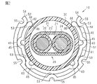
- FIG. 2 is a cross-sectional view showing a part of the wire harness of one embodiment.
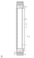
- FIG. 3 is a side view showing a part of the wire harness of one embodiment.
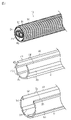
- FIG. 4 is a partially exploded perspective view of the wire harness of one embodiment.
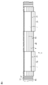
- FIG. 5 is a side view showing a part of another example wire harness.
- FIG. 6 is a side view showing a part of another example wire harness.
- FIG. 7 is a side view showing a part of another example wire harness.
- FIG. 8 is a cross-sectional view showing a part of a wire harness of another example.
- the wire harness of the present disclosure is [1] An electric wire member, a tubular exterior member that covers the outer periphery of the electric wire member, a first path restricting member attached to the outer peripheral side of the exterior member, and a first route restricting member attached to the outer peripheral side of the first path regulating member.
- the first route restricting member includes a two-way restricting member, and the first route restricting member is formed by a first main body portion that covers a part of the outer periphery of the exterior member and both ends in the circumferential direction of the first main body portion.
- the second route restricting member has a first insertion port, which extends along the length direction of the one route restricting member and extends over the entire length direction, and is configured to allow the exterior member to be inserted. It is formed by a second main body portion that covers a part of the outer periphery of the first path restricting member and both ends in the circumferential direction of the second main body portion, and is formed along the length direction of the second path restricting member and has the length. It has a second insertion slot that extends throughout the direction and is configured to allow the first path restricting member to be inserted.
- the first path restricting member can be retrofitted to the outer periphery of the exterior member through the first insertion slot.
- the second route restricting member can be retrofitted to the outer periphery of the first route restricting member through the second insertion slot. Since the first path regulating member and the second path regulating member are doubly attached to the outer peripheral side of the exterior member, for example, the bending rigidity of the wire harness at the portion can be increased. Therefore, the deviation from the path of the electric wire member can be suppressed.
- the first path restricting member and the second path regulating member are doubly attached to the outer peripheral side of the exterior member, for example, when the portion is arranged at a position close to the heat source of the vehicle, the electric wire member is attached. It is possible to prevent the temperature of the cable from rising. From these things, the protection function of the electric wire member can be enhanced.
- the second route restricting member is preferably made of metal. According to the same configuration, since the second path restricting member is made of metal, the temperature of the electric wire member is further suppressed in the relevant portion, for example, when it is arranged near the heat source of the vehicle. can.
- the first route restricting member is preferably made of resin. According to the same configuration, since the first path restricting member is made of resin, it is possible to prevent the exterior member from rubbing against the metal member and being worn. That is, if the first path restricting member is made of metal, the exterior member may be easily worn by rubbing against the metal first path regulating member, but this can be avoided.
- the second path restricting member is preferably made of resin and is colored. According to the same configuration, since the second path restricting member is made of resin and is colored, the operator can recognize, for example, the type of wire harness according to the color. Therefore, for example, when the electric wire member includes a high-voltage electric wire, it is possible to call attention so that the operator does not accidentally cut the electric wire member. Further, since the second path restricting member is made of resin, it can be easily manufactured by, for example, mixing a paint with a resin material and molding it without using a painting process or the like. That is, if the second path restricting member is made of metal, a painting step or the like is required after molding, which can be avoided and easily manufactured. Further, for example, in the case of a second path restricting member that is painted after molding, the color cannot be visually recognized when worn, but this can be avoided and the durability can be improved.
- the second route restricting member is preferably shorter than the first route restricting member. According to the same configuration, since the second path regulating member is shorter than the first path regulating member, for example, the bending rigidity of the wire harness can be locally increased at the portion where the second path regulating member is arranged. .. Therefore, for example, it is possible to reduce the weight of the entire wire harness while locally increasing the bending rigidity of the wire harness only in a particularly necessary portion.
- a plurality of the second route regulating members are attached to the first route regulating member, and the plurality of the second route regulating members are separated from each other in the length direction of the first route regulating member. Is preferable.
- the bending rigidity of the wire harness can be locally increased at each of a plurality of parts where the second path restricting member is arranged. Therefore, for example, it is possible to reduce the weight of the entire wire harness while locally increasing the bending rigidity of the wire harness only at a plurality of particularly necessary portions.
- the first route restricting member is preferably shorter than the second route restricting member.
- the bending rigidity of the wire harness can be locally increased at the portion where the first path regulating member is arranged. .. Therefore, for example, it is possible to reduce the weight of the entire wire harness while locally increasing the bending rigidity of the wire harness only in a particularly necessary portion.
- the portion where the air layer is formed between the exterior member and the second path restricting member it becomes difficult for heat to be transferred to the inside. Therefore, for example, when the electric wire member is placed near the heat source of the vehicle, the temperature of the electric wire member is high. Can be more suppressed from rising.
- a plurality of the first route restricting members are attached to the exterior member, and the plurality of the first route restricting members are separated from each other in the length direction of the exterior member, and the second route regulating member is regulated. It is preferable that the member is attached over a plurality of the first path restricting members.
- the bending rigidity of the wire harness can be locally increased at each of a plurality of parts where the first path restricting member is arranged. Therefore, for example, it is possible to reduce the weight of the entire wire harness while locally increasing the bending rigidity of the wire harness only at a plurality of particularly necessary portions.
- At least one of the first route restricting member and the second route restricting member has a protruding portion protruding from the first main body portion or the second main body portion. According to the same configuration, since at least one of the first route restricting member and the second route restricting member has a protruding portion protruding from the first main body portion or the second main body portion, the first route regulating member and the second route regulating member are regulated. The bending rigidity of at least one of the members can be increased. Therefore, the deviation from the path of the electric wire member can be further suppressed.
- the protrusions include a first protrusion that protrudes from the first main body toward the second main body, and a second protrusion that protrudes from the second main body toward the first main body. It is preferable that the first protruding portion and the second protruding portion are in contact with each other.
- the first protruding portion protruding from the first main body portion toward the second main body portion and the second protruding portion protruding from the second main body portion toward the first main body portion can come into contact with each other. Therefore, it is possible to prevent the second route restricting member from rotating in the circumferential direction with respect to the first route restricting member. Further, between the first main body portion and the second main body portion, the portion where the first protruding portion and the second protruding portion are not provided becomes an air layer in which heat is difficult to transfer, so that it is close to, for example, a vehicle heat source. It is possible to further suppress the temperature rise of the electric wire member when it is arranged at the position.
- the second route restricting member is attached to the first route restricting member so that the direction of the second insertion port is different from the direction of the first insertion port.
- the second path restricting member is attached to the first path restricting member so that the direction of the second insertion port is different from the direction of the first insertion port, so that the bending rigidity of the wire harness is lowered.
- the bending rigidity of the wire harness may be reduced intensively in the direction of that direction, but this is avoided. be able to.
- the first path restricting member has a pair of holding protrusions that project from the inner surface of the first main body toward the exterior member and come into contact with the outer surface of the exterior member.
- the first path restricting member since the first path restricting member has a pair of holding protrusions that protrude from the inner surface of the first main body toward the exterior member and come into contact with the outer surface of the exterior member, the first insertion is performed. It is possible to suppress the detachment of the first route restricting member from the exterior member through the mouth.
- the holding protrusions protrude from the inner surfaces at both ends of the first main body in the circumferential direction. According to the same configuration, for example, as compared with the case where the holding protrusions protrude from the inner surface of the first main body portion at a position slightly distant from both ends in the circumferential direction, the protrusions from the exterior member through the first insertion port are used. The detachment of the first route restricting member can be further suppressed.
- the wire harness 10 shown in FIG. 1 electrically connects two or three or more electric devices.
- the wire harness 10 electrically connects an inverter 11 installed at the front of a vehicle V such as a hybrid vehicle or an electric vehicle and a high-pressure battery 12 installed behind the vehicle V from the inverter 11. ..
- the wire harness 10 is arranged so as to pass under the floor of the vehicle V, for example.
- the intermediate portion of the wire harness 10 in the length direction is arranged so as to pass outside the vehicle interior such as under the floor of the vehicle V.
- the inverter 11 is connected to a motor for driving wheels (not shown), which is a power source for traveling the vehicle.
- the inverter 11 generates AC power from the DC power of the high-voltage battery 12, and supplies the AC power to the motor.
- the high voltage battery 12 is, for example, a battery capable of supplying a voltage of several hundred volts.
- the wire harness 10 includes an electric wire member 20 that electrically connects the electric devices to each other, and a tubular exterior member 30 that covers the outer periphery of the electric wire member 20. Further, the wire harness 10 includes a first path regulating member 40 attached to the outer peripheral side of the exterior member 30, and a second path regulating member 50 attached to the outer peripheral side of the first path regulating member 40.
- the first route restricting member 40 and the second route restricting member 50 regulate the route to which the electric wire member 20 is arranged. Specifically, in the first route regulating member 40 and the second route regulating member 50, the electric wire member 20 is more difficult to bend than the electric wire member 20 in the state where the first route regulating member 40 and the second route regulating member 50 are not attached. It acts like this and suppresses the deviation of the electric wire member 20 from the path.
- the electric wire member 20 has one or a plurality of electric wires 21 and a braided member 24 that collectively covers the outer periphery of each electric wire 21.
- the electric wire member 20 of the present embodiment has two electric wires 21. One end of the electric wire member 20 is connected to the inverter 11 via the connector C1, and the other end of the electric wire member 20 is connected to the high voltage battery 12 via the connector C2.
- the electric wire member 20 is formed in a long shape so as to extend in the front-rear direction of the vehicle, for example.
- the electric wire 21 is, for example, a high-voltage electric wire that can handle high voltage and large current.
- the electric wire 21 may be, for example, a non-shielded electric wire that does not have an electromagnetically shielded structure by itself, or may be a shielded electric wire that has an electromagnetically shielded structure by itself.
- the electric wire 21 is a coated electric wire having a core wire 22 made of a conductor and an insulating coating 23 covering the outer periphery of the core wire 22.
- the core wire 22 includes, for example, a stranded wire made by twisting a plurality of metal strands, a columnar conductor made of one columnar metal rod having a solid structure inside, a tubular conductor having a hollow structure inside, and the like. Can be used. Further, as the core wire 22, for example, a conductor in which a plurality of types of conductors such as a stranded wire, a columnar conductor, and a tubular conductor are combined can be used. Examples of the columnar conductor include a single core wire and a bus bar.
- the core wire 22 of the present embodiment is a stranded wire.
- a metal material such as copper-based or aluminum-based can be used.
- the cross-sectional shape obtained by cutting the core wire 22 by a plane orthogonal to the length direction of the core wire 22, that is, the length direction of the electric wire 21 can be any shape.
- the cross-sectional shape of the core wire 22 is formed, for example, into a circular shape, a semicircular shape, a polygonal shape, a square shape, a flat shape, or the like.
- the cross-sectional shape of the core wire 22 of the present embodiment is formed in a circular shape.
- the insulating coating 23 covers, for example, the outer peripheral surface of the core wire 22 over the entire circumference.
- the insulating coating 23 is made of an insulating material such as a synthetic resin.
- a synthetic resin containing a polyolefin resin such as cross-linked polyethylene or cross-linked polypropylene as a main component can be used.
- the material of the insulating coating 23 one kind of material may be used alone, or two or more kinds of materials may be used in combination as appropriate.
- the braided member 24 has, for example, a cylindrical shape that collectively covers the outer periphery of each electric wire 21 as a whole.
- the braided member 24 is provided, for example, so as to cover the outer periphery of each electric wire 21 over substantially the entire length direction of the electric wire 21.
- a braided wire in which a plurality of metal strands are knitted or a braided wire in which a metal strand and a resin strand are combined can be used.
- a metal material such as copper-based or aluminum-based can be used.
- the braided member 24 is connected to the ground at, for example, the connectors C1 and C2.
- the exterior member 30 has a cylindrical shape that covers the outer periphery of the electric wire member 20 over the entire circumference in the circumferential direction.
- the exterior member 30 is hermetically sealed throughout the circumferential direction.
- the exterior member 30 is provided, for example, so as to cover a part of the outer circumference of the electric wire member 20 in the length direction.
- the exterior member 30 of the present embodiment is a corrugated tube having a bellows structure in which annular convex portions 31 and annular concave portions 32 are alternately provided along the length direction thereof.
- the exterior member 30 has flexibility.
- a resin material having conductivity or a resin material having no conductivity can be used.
- synthetic resins such as polyolefin, polyamide, polyester, and ABS resin can be used.
- the first path restricting member 40 covers a range larger than half of the outer circumference of the exterior member 30 in the circumferential direction and extends along the length direction of the exterior member 30. ing.
- the first route restricting member 40 of the present embodiment is attached to, for example, the outer periphery of a portion of the wiring path of the electric wire member 20 where the exterior member 30 such as under the floor of the vehicle V extends linearly.
- the first route restricting member 40 is made of resin.
- a synthetic resin such as polypropylene, polyamide, or polyacetal can be used.
- the first path restricting member 40 can be manufactured by a well-known manufacturing method such as extrusion molding or injection molding.
- the first path restricting member 40 of the present embodiment has a constant cross-sectional shape when viewed from the length direction.
- the first path restricting member 40 is an extruded product.
- the first path restricting member 40 is more rigid than the exterior member 30. That is, the first route restricting member 40 is set to be harder to bend than the exterior member 30. In other words, the first path restricting member 40 is set to have a higher bending rigidity than the exterior member 30.
- the first path restricting member 40 has a first main body portion 41, a first insertion port 42, and a first protruding portion 43 as a protruding portion.
- the first main body portion 41 is formed so as to cover a range larger than half of the outer periphery of the exterior member 30 in the circumferential direction.
- the first insertion port 42 is formed by both end portions 44 in the circumferential direction of the first main body portion 41, extends along the length direction of the first path restricting member 40 and extends over the entire length direction, and is an exterior member 30. Is configured to be insertable.
- the first protruding portion 43 protrudes from the outer periphery of the first main body portion 41 and extends along the length direction of the first path restricting member 40.
- a plurality of first protruding portions 43 are provided in the circumferential direction of the first main body portion 41.
- Two first protrusions 43 of the present embodiment are provided on one side and two on the other side of the center of the first main body 41 in the circumferential direction.
- the first route restricting member 40 of the present embodiment has a first groove portion 45.
- the first groove portion 45 is recessed from the inner circumference of the first main body portion 41 at a position corresponding to the first protruding portion 43, and extends along the length direction of the first path restricting member 40.
- the first protruding portion 43 is formed so as to project to the outside of the first main body portion 41 while keeping the thickness of the first main body portion 41 substantially constant, and the first groove portion 45 is the first.
- the protrusion 43 is recessed corresponding to the overhanging portion.
- the first path restricting member 40 projects toward the exterior member 30 inserted inside and has a pair of holding protrusions 46 that come into contact with the outer surface of the exterior member 30, more specifically, the outer surface of the annular convex portion 31.
- the holding protrusion 46 protrudes from the inner surface of both end portions 44 in the circumferential direction of the first main body portion 41.
- the cross-sectional shape of the holding protrusion 46 is, for example, a semicircular shape.
- Each holding protrusion 46 extends along the length direction over the entire length direction of the first path restricting member 40.
- the first insertion port 42 extends over the entire length direction of the first path restricting member 40.
- the opening width of the first insertion port 42 that is, the shortest distance between both end portions 44 in the circumferential direction of the first main body portion 41 is smaller than the outer diameter of the exterior member 30.
- the first path restricting member 40 When the exterior member 30 is inserted into the first insertion slot 42 from a direction orthogonal to the length direction, the first path restricting member 40 is elastically deformed and the opening width of the first insertion slot 42 is increased. When the exterior member 30 is inserted into the first path restricting member 40, the first path restricting member 40 elastically returns to return to its original shape. As a result, the opening width of the first insertion port 42 becomes smaller than the outer diameter of the exterior member 30, so that the first route restricting member 40 is attached to the exterior member 30.
- the second route restricting member 50 covers a range larger than half of the outer circumference of the first route restricting member 40 in the circumferential direction, and the first route restricting member 40. It extends along the length direction of 40.
- the second route restricting member 50 is shorter than the first route restricting member 40.
- the second route restricting member 50 is attached to the central portion of the first route restricting member 40 in the length direction. That is, the second route restricting member 50 is attached to the first route restricting member 40 so as not to cover both ends of the first route restricting member 40 in the length direction.
- the second route restricting member 50 is made of resin. Further, as the material of the second path restricting member 50, for example, a synthetic resin such as polypropylene, polyamide, or polyacetal can be used.
- the second path restricting member 50 can be manufactured by a well-known manufacturing method such as extrusion molding or injection molding.
- the second path restricting member 50 of the present embodiment has a constant cross-sectional shape when viewed from the length direction.
- the second path restricting member 50 is an extruded product.
- the second path restricting member 50 is harder than the exterior member 30. That is, the second path restricting member 50 is set to be harder to bend than the exterior member 30. In other words, the second path restricting member 50 is set to have a higher bending rigidity than the exterior member 30.
- the second route restricting member 50 is colored.
- the second path restricting member 50 of the present embodiment is molded by mixing a paint with a resin material.
- the second path restricting member 50 is made of a colored synthetic resin material.
- the color of the second path restricting member 50 is set to a color that allows the operator to recognize that the electric wire 21 included in the electric wire member 20 of the wire harness 10 is a high-voltage electric wire.
- the second path restricting member 50 has a second main body portion 51, a second insertion port 52, and a second protruding portion 53 as a protruding portion.
- the second main body 51 is formed so as to cover almost the entire outer circumference of the first path restricting member 40.
- the second insertion port 52 is formed by both end portions 54 in the circumferential direction of the second main body portion 51, extends along the length direction of the second path restricting member 50 and extends over the entire length direction, and is the first path.
- the regulating member 40 is configured to be insertable.
- the second protruding portion 53 protrudes from the inner circumference of the second main body portion 51 and extends along the length direction of the second path restricting member 50.
- a plurality of second protruding portions 53 are provided in the circumferential direction of the second main body portion 51.
- Two second protrusions 53 of the present embodiment are provided on one side and the other side of the center of the second main body 51 in the circumferential direction.
- the second protruding portion 53 is provided at both end portions 54 in the circumferential direction of the second main body portion 51.
- the second protruding portion 53 is provided at the center of the second main body portion 51 in the circumferential direction.
- the second route restricting member 50 of the present embodiment has a second groove portion 55.
- the second groove portion 55 is recessed from the outer periphery of the second main body portion 51 at a position corresponding to the second protruding portion 53, and extends along the length direction of the second path restricting member 50. That is, the second protruding portion 53 is formed so as to project inside the second main body portion 51 while keeping the thickness of the second main body portion 51 substantially constant, and the second groove portion 55 is the second.
- the protrusion 53 is recessed corresponding to the overhanging portion.
- the first protruding portion 43 protrudes toward the second main body portion 51.
- the top of the first protruding portion 43 is set to come into contact with the second main body portion 51.
- the second protruding portion 53 protrudes toward the first main body portion 41.
- the top of the second protruding portion 53 is set to come into contact with the first main body portion 41.
- a part of the first protruding portion 43 and the second protruding portion 53 can be brought into contact with each other in the circumferential direction of the first path regulating member 40 and the second path regulating member 50.
- a part of the second protruding portion 53 is in contact with the first protruding portion 43 in one direction in the circumferential direction of the first path restricting member 40.
- the second route restricting member 50 is restricted from rotating in both circumferential directions with respect to the first route restricting member 40.
- the second insertion port 52 extends over the entire length direction of the second path restricting member 50.
- the opening width of the second insertion port 52 that is, the shortest distance between both end portions 54 in the circumferential direction of the second main body portion 51 is smaller than the maximum outer diameter of the first path restricting member 40.
- the second route restricting member 50 is attached to the first route restricting member 40 so that the direction of the second insertion port 52 coincides with the direction of the first insertion port 42.
- the second path restricting member 50 is elastically deformed and the opening width of the second insertion port 52 is increased.
- the second path restricting member 50 elastically returns to return to its original shape.
- the opening width of the second insertion port 52 becomes smaller than the outer diameter of the first route restricting member 40, so that the second route restricting member 50 is attached to the first route restricting member 40.
- the first path restricting member 40 can be retrofitted to the outer periphery of the exterior member 30 through the first insertion port 42.
- the first path restricting member 40 can be assembled to the exterior member 30 from a direction orthogonal to the length direction of the exterior member 30.
- the second route restricting member 50 can be retrofitted to the outer periphery of the first route restricting member 40 through the second insertion port 52.
- the second route restricting member 50 can be assembled to the first route restricting member 40 from a direction orthogonal to the length direction of the first route restricting member 40.
- the wire harness 10 bends even if vibration or some external force is applied. Is suppressed.
- the effect of this embodiment will be described.
- the first route restricting member 40 can be retrofitted to the outer periphery of the exterior member 30 through the first insertion port 42.
- the second route restricting member 50 can be retrofitted to the outer periphery of the first route restricting member 40 through the second insertion port 52. Since the first path regulating member 40 and the second path regulating member 50 are double-mounted on the outer peripheral side of the exterior member 30, for example, the bending rigidity of the wire harness 10 at the portion can be increased. Therefore, the deviation from the path of the electric wire member 20 can be suppressed.
- first route restricting member 40 and the second route restricting member 50 are doubly attached to the outer peripheral side of the exterior member 30, for example, when the portion is arranged at a position close to the heat source of the vehicle V, etc. In addition, it is possible to prevent the temperature of the electric wire member 20 from rising. From these facts, in the wire harness 10 of this embodiment, the protection function of the electric wire member 20 can be enhanced.
- the first path restricting member 40 is made of resin, it is possible to prevent the exterior member 30 from rubbing against the metal member and being worn. That is, if the first path restricting member 40 is made of metal, the exterior member 30 may rub against the metal first path regulating member 40 and easily wear, but this can be avoided.
- the second path restricting member 50 Since the second path restricting member 50 is made of resin and is colored, the operator can recognize, for example, the type of the wire harness 10 according to the color. Therefore, for example, when the electric wire member 20 includes a high-voltage electric wire, it is possible to call attention so that the operator does not accidentally cut the electric wire member 20. Further, since the second path restricting member 50 is made of resin, it can be easily manufactured by, for example, mixing a paint with a resin material and molding it without using a painting process or the like. That is, if the second path restricting member 50 is made of metal, a painting step or the like is required after molding, which can be avoided and easily manufactured. Further, for example, in the case of the second path restricting member 50 which is painted after molding, the color cannot be visually recognized when worn, but this can be avoided and the durability can be improved.
- the bending rigidity of the wire harness 10 can be locally increased at the portion where the second path regulating member 50 is arranged. can. Therefore, for example, the weight of the entire wire harness 10 can be reduced while the bending rigidity of the wire harness 10 can be increased locally only in a particularly necessary portion.
- the first path restricting member 40 has a first protruding portion 43 as a protruding portion protruding from the first main body portion 41.
- the second path restricting member 50 has a second protruding portion 53 as a protruding portion protruding from the second main body portion 51. Therefore, the bending rigidity of the first path regulating member 40 and the second path regulating member 50 can be increased. Therefore, the deviation from the path of the electric wire member 20 can be further suppressed.
- the first path restricting member 40 has a pair of holding protrusions 46 that project from the inner surface of the first main body 41 toward the exterior member 30 and come into contact with the outer surface of the exterior member 30. 1 Detachment of the first path restricting member 40 from the exterior member 30 through the insertion port 42 can be suppressed.
- the holding protrusion 46 protrudes from the inner surface of both end portions 44 in the circumferential direction of the first main body portion 41. Therefore, for example, as compared with the case where the holding protrusion 46 protrudes from the inner surface of the first main body 41 at a position slightly distant from both ends 44 in the circumferential direction, the exterior member 30 through the first insertion port 42 The detachment of the first route restricting member 40 can be further suppressed.
- one second route restricting member 50 is attached to one first route restricting member 40, but the present invention is not limited to this, and a plurality of first route restricting members 40 are attached to one first route restricting member 40. 2
- the configuration may be such that the route restricting member 50 is attached.
- two second route regulating members 50 are attached to one first route regulating member 40, and the two second route regulating members 50 are the first route regulating member 40. It may be configured to be separated from each other in the length direction.
- the bending rigidity of the wire harness 10 can be locally increased at each of a plurality of portions where the second path restricting member 50 is arranged. Therefore, for example, it is possible to reduce the weight of the entire wire harness 10 while locally increasing the bending rigidity of the wire harness 10 only at a plurality of particularly necessary portions.
- the second route restricting member 50 has a shorter configuration than the first route restricting member 40, but the length of the second route restricting member 50 is not limited to this, and the length of the second route restricting member 50 is the first route restricting member 40. It may be longer than the length of.
- the second route restricting member 50 is longer than the first route restricting member 40, and the first route restricting member 40 covers the entire length direction of the first route restricting member 40. It may be an attached configuration.
- the bending rigidity of the wire harness 10 is locally increased at the portion where the first path regulating member 40 is arranged. be able to. Therefore, for example, the weight of the entire wire harness 10 can be reduced while the bending rigidity of the wire harness 10 can be increased locally only in a particularly necessary portion. Further, in the portion where the air layer is formed between the exterior member 30 and the second path restricting member 50, it becomes difficult for heat to be transferred to the inside. Therefore, for example, when the electric wire is arranged near the heat source of the vehicle V, the electric wire is used. It is possible to further suppress the temperature rise of the member 20.
- a plurality of first route restricting members 40 are attached to the exterior member 30.
- the plurality of first path restricting members 40 are separated from each other in the length direction of the exterior member 30.
- the second route restricting member 50 is attached to the plurality of first route restricting members 40. That is, the second route restricting member 50 is attached to the plurality of first route restricting members 40 so as to collectively cover the plurality of first route restricting members 40.
- the bending rigidity of the wire harness 10 can be locally increased at each of the plurality of portions where the first path restricting member 40 is arranged. Therefore, for example, it is possible to reduce the weight of the entire wire harness 10 while locally increasing the bending rigidity of the wire harness 10 only at a plurality of particularly necessary portions.
- the second path restricting member 50 is attached to the first path restricting member 40 so that the direction of the second insertion port 52 matches the direction of the first insertion port 42.
- the orientation of the second insertion slot 52 may be different from that of the second insertion slot 52.
- the second path restricting member 50 may be attached to the first path restricting member 40 so that the direction of the second insertion port 52 is different from the direction of the first insertion port 42. good.
- the orientation of the second insertion slot 52 is set to be opposite to the orientation of the first insertion slot 42.
- the first insertion port 42 is covered with the second main body portion 51.
- the orientation of the second insertion slot 52 does not have to be the exact opposite of the orientation of the first insertion slot 42.
- the direction in which the bending rigidity of the wire harness 10 decreases is not concentrated in one direction. That is, if the direction of the second insertion port 52 and the direction of the first insertion port 42 match, the bending rigidity of the wire harness 10 may be reduced intensively in the direction of the direction. Can be avoided. In other words, by adjusting the direction of the first insertion port 42 and the direction of the second insertion port 52, it is possible to adjust the direction in which the bending rigidity of the wire harness 10 increases or decreases in a desired direction. Further, since the first insertion port 42 is covered by the second main body portion 51, it is possible to suppress the intrusion of foreign matter into the exterior member 30 side at the portion.
- the first route restricting member 40 is made of resin, but the present invention is not limited to this, and may be made of metal, for example.
- the first path restricting member 40 may be made of a metal material such as iron-based, copper-based, or aluminum-based.
- the second path restricting member 50 is made of resin, but the present invention is not limited to this, and may be made of metal, for example.
- the second path restricting member 50 may be made of a metal material such as iron-based, copper-based, or aluminum-based.
- the second path restricting member 50 is made of metal in this way, it is possible to suppress an increase in the temperature of the electric wire member 20 when, for example, it is arranged at a position close to the heat source of the vehicle V.
- the first path regulating member 40 is made of resin and the second path regulating member 50 is made of metal, the exterior member 30 is prevented from being worn by rubbing against the metal second path regulating member 50.
- the second route restricting member 50 is shorter than the first route restricting member 40 and does not cover both ends of the first route restricting member 40 in the length direction, the exterior member 30 is made of metal and the second route restricting member 30 is made of metal. Rubbing with the member 50 is further suppressed.
- the second path restricting member 50 is colored, and the electric wire 21 included in the electric wire member 20 is set to a color that can be recognized by the operator as a high-voltage electric wire. Not limited. That is, the second path restricting member 50 may have a color irrelevant to the type of the electric wire 21 or the like.
- the first path restricting member 40 has a first protruding portion 43 as a protruding portion protruding from the first main body portion 41, but the present invention is not limited to this, and the first protruding portion 43 is provided. It may be configured not to be used.
- the second path restricting member 50 is said to have a second protruding portion 53 as a protruding portion protruding from the second main body portion 51, but the present invention is not limited to this, and the configuration does not have the second protruding portion 53. May be.
- the first route restricting member 40 may not have the first protruding portion 43, and the second route restricting member 50 may not have the second protruding portion 53.
- first protruding portion 43 is said to protrude from the outer periphery of the first main body portion 41, but the present invention is not limited to this, and the first protruding portion 43 may be configured to protrude from the inner circumference of the first main body portion 41.
- second protruding portion 53 is said to protrude from the inner circumference of the second main body 51, but the present invention is not limited to this, and the second protruding portion 53 may be configured to protrude from the outer circumference of the second main body 51.
- first protruding portion 43 and the second protruding portion 53 can be brought into contact with each other in the circumferential direction of the first route restricting member 40 and the second route restricting member 50.
- the configuration is not limited to this, and the configuration may be inaccessible. Further, the number of the first protruding portion 43 and the second protruding portion 53 may be changed.
- the first path restricting member 40 has the first groove portion 45 at a position corresponding to the first protrusion 43, but the present invention is not limited to this, and the first groove portion 45 is not provided. May be.
- the second path restricting member 50 has the second groove portion 55 at a position corresponding to the second protrusion 53, but the present invention is not limited to this, and the second groove portion 55 is not provided. May be.
- the first path restricting member 40 has a holding protrusion 46 that comes into contact with the outer surface of the exterior member 30, but is not limited to this, and has a holding protrusion 46. It may not be configured. Further, the holding protrusion 46 may be configured to protrude from the inner surface at a position slightly distant from both end portions 44 in the circumferential direction of the first main body portion 41.
- the first route regulating member 40 and the second route regulating member 50 are said to be harder than the exterior member 30, but the hardness is not limited to this, and the hardness is equal to or less than that of the exterior member 30. May be. That is, in the first route regulating member 40 and the second route regulating member 50, the electric wire member 20 is less likely to bend than the electric wire member 20 in the state where the first route regulating member 40 and the second route regulating member 50 are not attached. It does not have to be harder than the exterior member 30 if it acts on.
- the exterior member 30 may be provided with a metal layer containing a metal material on the outer surface of the corrugated tube.
- a metal layer can be provided, for example, by a plating process. It is preferable that the metal layer is provided on the entire outer surface of the annular convex portion 31 and the annular concave portion 32 of the corrugated tube.
- a metal material such as aluminum having a small emissivity. According to such a configuration, it is possible to suppress an increase in the temperature inside the exterior member 30, and eventually the temperature of the electric wire member 20, when the vehicle is arranged at a position close to the heat source of the vehicle.
- the exterior member 30 may have a slit extending in the length direction of the exterior member 30.
- the electric wire member 20 may have one electric wire 21 or may have three or more electric wires 21. -The wire member 20 may omit the braided member 24.
- the first route regulating member 40 and the second route regulating member 50 are not limited to those provided under the floor of the vehicle V.
- the first route restricting member 40 and the second route restricting member 50 may be provided, for example, in the passenger compartment of the vehicle V as long as they are linearly extending portions of the wiring path of the electric wire member 20.
- the first route regulating member 40 may be referred to as a radially inner or smaller diameter route regulating member, and the second route regulating member 50 may be referred to as a radially outer or larger diameter route regulating member. be.
- the wire harness (10) is Wire member (20) and A cylindrical exterior member (30) that covers the outer circumference of the electric wire member (20), and A first path restricting member (40) having a predetermined length profile that can be a linear profile and a predetermined cross-sectional profile that can be a C-shaped cross-section profile, such as a snap to the outer peripheral surface of the exterior member (30).
- the first path restricting member (40) which is attached by a fit and configured to regulate the length shape of the wire harness (10).
- a second path restricting member (50) having a predetermined length profile that can be a linear profile and a predetermined cross-sectional profile that can be a C-shaped cross-sectional profile, the outer peripheral surface of the first path restricting member (40).
- the second path restricting member (50) which is attached to, for example, by a snap fit and is configured to regulate the length shape of the wire harness (10), can be provided.
- the first path restricting member (40) is the first length position of the wire harness (10) and the first. It may be attached to the wire harness (10) so as to cover a second length position different from the length position.
- the wire harness (10) is The second route restricting member (50) attached to the first route restricting member (40) at the first length position, and the second route restricting member (50). It can be provided with another second route restricting member (50) attached to the first route restricting member (40) at the second length position.
- the second route restricting member (50) partially comprises the first route restricting member (40) in the length direction. You may cover it.
- the second route restricting member (50) completely covers the first route restricting member (40) in the length direction. You can do it.
- the wire harness (10) is The first path restricting member (40) attached to the exterior member (30) at the first length position of the wire harness (10), and With another first path restricting member (40) attached to the exterior member (30) at a second length position of the wire harness (10) different from the first length position.
- the first path restricting member (40) at the first length position and the second path regulating member (50) covering another first path regulating member (40) at the second length position are provided. be able to.
- the outer surface of the first path restricting member (40) has a plurality of first projecting portions (43) extending outward over the entire length of the first path regulating member (40) and projecting outward in the radial direction, and the first projecting portion (43). May have a smooth outer surface except The inner surface of the second path restricting member (50) extends over the entire length of the second path regulating member (50) and projects inward in the radial direction, and the second projecting portion (53). May have a smooth inner surface excluding Each first protrusion (43) of the first path restricting member (40) may come into contact with the smooth inner surface of the second path restricting member (50).
- Each second protrusion (53) of the second path restricting member (50) may come into contact with the smooth outer surface of the first path restricting member (40).
- An air layer may be formed between the smooth outer surface of the first path restricting member (40) and the smooth inner surface of the second path restricting member (50).
- One or more first protrusions (43) of the first path restricting member (40) may come into contact with one corresponding second protrusion (53) of the second path restricting member (50).
- each first protrusion (43) of the first path restricting member (40) corresponds to the second path restricting member (50). It may be in contact with one second protrusion (53).
- the outer surface of the exterior member (30) is the first route restricting member (40) and the second route restricting member. Includes an exposed outer surface that is not covered by (50) and is exposed from the first insertion port (42) of the first path restricting member (40) and the second insertion port (52) of the second path restricting member (50). It's fine.
- the second route restricting member may be an end portion (54) of the second route restricting member (50).
- the top position of (50) may coincide with the top position of the exterior member (30), which may be a part of the outer surface of the exterior member (30), in the height direction.
- Wire harness 11 Inverter 12 High-voltage battery 20 Electric wire member 21 Electric wire 22 Core wire 23 Insulation coating 24 Braided member 30 Exterior member 31 Circular convex part 32 Circular concave part 40 1st route regulation member 41 1st main body 42 1st insertion port 43 1st Protruding part (protruding part) 44 End 45 First groove 46 Holding protrusion 50 Second path restricting member 51 Second main body 52 Second insertion port 53 Second protrusion (projection) 54 End 55 Second groove C1 connector C2 connector V Vehicle
Landscapes
- Engineering & Computer Science (AREA)
- Mechanical Engineering (AREA)
- Architecture (AREA)
- Civil Engineering (AREA)
- Structural Engineering (AREA)
- General Engineering & Computer Science (AREA)
- Details Of Indoor Wiring (AREA)
- Insulated Conductors (AREA)
- Protection Of Pipes Against Damage, Friction, And Corrosion (AREA)
Abstract
Description
最初に本開示の実施態様を列記して説明する。
本開示のワイヤハーネスは、
[1]電線部材と、前記電線部材の外周を覆う筒状の外装部材と、前記外装部材の外周側に取り付けられる第1経路規制部材と、前記第1経路規制部材の外周側に取り付けられる第2経路規制部材と、を備え、前記第1経路規制部材は、前記外装部材の外周の一部を覆う第1本体部と、前記第1本体部における周方向の両端部によって形成され、前記第1経路規制部材の長さ方向に沿うとともに当該長さ方向の全体にわたって延びており、前記外装部材が挿入可能に構成された第1挿入口と、を有し、前記第2経路規制部材は、前記第1経路規制部材の外周の一部を覆う第2本体部と、前記第2本体部における周方向の両端部によって形成され、前記第2経路規制部材の長さ方向に沿うとともに当該長さ方向の全体にわたって延びており、前記第1経路規制部材が挿入可能に構成された第2挿入口と、を有する。
同構成によれば、第2経路規制部材は、金属製であるため、当該部分では、例えば、車両の熱源に近い位置に配置された場合等に、電線部材の温度が上昇することをより抑制できる。
同構成によれば、第1経路規制部材は、樹脂製であるため、外装部材が金属製の部材と擦れて摩耗することを抑制できる。すなわち、第1経路規制部材が金属製であると、外装部材が、金属製の第1経路規制部材と擦れて摩耗し易くなる虞があるが、これを回避できる。
同構成によれば、第2経路規制部材は、樹脂製であり、有色であるため、例えば、色に応じてワイヤハーネスの種類等を作業者が認識可能となる。よって、例えば、電線部材が高圧電線を含む場合等、該電線部材を作業者が誤って切断しないように注意を促すことができる。また、第2経路規制部材は、樹脂製であるため、塗装工程等を用いずに、例えば、樹脂材に塗料を混ぜて成形することで容易に製造することができる。すなわち、第2経路規制部材を金属製とすると、成形後に塗装工程等が必要となるが、これを回避して容易に製造することができる。また、例えば、成形後に塗装してなる第2経路規制部材とした場合では、摩耗すると色を視認できなくなるが、これを回避でき、耐久性を高くすることが可能となる。
同構成によれば、第2経路規制部材は、第1経路規制部材よりも短いため、例えば、第2経路規制部材が配される部位で局所的にワイヤハーネスの曲げ剛性を高くすることができる。よって、例えば、特に必要な部位のみ局所的にワイヤハーネスの曲げ剛性をより高くしつつ、ワイヤハーネス全体は軽量化することができる。
同構成によれば、第1経路規制部材は、第2経路規制部材よりも短いため、例えば、第1経路規制部材が配される部位で局所的にワイヤハーネスの曲げ剛性を高くすることができる。よって、例えば、特に必要な部位のみ局所的にワイヤハーネスの曲げ剛性をより高くしつつ、ワイヤハーネス全体は軽量化することができる。また、外装部材と第2経路規制部材との間が空気層となる部位では、内側に熱が伝わり難くなるため、例えば、車両の熱源に近い位置に配置された場合等に、電線部材の温度が上昇することをより抑制できる。
同構成によれば、第1経路規制部材及び第2経路規制部材の少なくとも一方は、第1本体部または第2本体部から突出する突出部を有するため、第1経路規制部材及び第2経路規制部材の少なくとも一方の曲げ剛性を高くすることができる。よって、電線部材の経路からの逸脱をより抑えることができる。
同構成によれば、第2経路規制部材は、第2挿入口の向きが第1挿入口の向きと異なるように第1経路規制部材に取り付けられるため、ワイヤハーネスの曲げ剛性が低くなる方向が一方向に集中しない。すなわち、第2挿入口の向きと第1挿入口の向きとが一致していると、その向きの方向に集中的にワイヤハーネスの曲げ剛性が低くなってしまう虞があるが、それを回避することができる。言い換えると、第1挿入口の向きと第2挿入口の向きとを調整することで、ワイヤハーネスの曲げ剛性が高くなる方向や低くなる方向を所望の方向に調整することができる。
同構成によれば、例えば、保持用突出部が第1本体部における周方向の両端部から僅かに離れた位置の内面から突出している場合に比べて、第1挿入口を通じた外装部材からの第1経路規制部材の脱離をより抑制できる。
本開示のワイヤハーネスの具体例を、以下に図面を参照しつつ説明する。各図面では、説明の便宜上、構成の一部を誇張又は簡略化して示す場合がある。また、各部分の寸法比率については各図面で異なる場合がある。なお、本開示はこれらの例示に限定されるものではなく、特許請求の範囲によって示され、特許請求の範囲と均等の意味及び範囲内でのすべての変更が含まれることが意図される。本明細書における「直交」は厳密に直交の場合のみでなく、本実施形態における作用効果を奏する範囲内で概ね直交の場合も含まれる。また、本明細書における「円」や「円弧」は厳密に円や円弧の場合のみでなく、本実施形態における作用効果を奏する範囲内で概ね円や円弧の場合も含まれる。
図1に示すワイヤハーネス10は、2個又は3個以上の電気機器を電気的に接続する。ワイヤハーネス10は、例えば、ハイブリッド車や電気自動車等の車両Vの前部に設置されたインバータ11と、そのインバータ11よりも車両Vの後方に設置された高圧バッテリ12とを電気的に接続する。ワイヤハーネス10は、例えば、車両Vの床下等を通るように配索される。例えば、ワイヤハーネス10の長さ方向の中間部が車両Vの床下等の車室外を通るように配索される。
電線部材20は、1本又は複数本の電線21と、各電線21の外周を一括して覆う編組部材24とを有している。本実施形態の電線部材20は、2本の電線21を有している。電線部材20の一端部はコネクタC1を介してインバータ11と接続され、電線部材20の他端部はコネクタC2を介して高圧バッテリ12と接続されている。電線部材20は、例えば、車両の前後方向に延びるように長尺状に形成されている。電線21は、例えば、高電圧・大電流に対応可能な高圧電線である。電線21は、例えば、自身に電磁シールド構造を有しないノンシールド電線であってもよいし、自身に電磁シールド構造を有するシールド電線であってもよい。
図2に示すように、電線21は、導体よりなる芯線22と、芯線22の外周を被覆する絶縁被覆23とを有する被覆電線である。
芯線22としては、例えば、複数の金属素線をより合わせてなる撚線、内部が中実構造をなす柱状の1本の金属棒からなる柱状導体や、内部が中空構造をなす筒状導体などを用いることができる。また、芯線22として、例えば、撚線、柱状導体、筒状導体等の複数種類の導体を組み合わせたものを用いることもできる。柱状導体としては、例えば、単芯線やバスバなどを挙げることができる。本実施形態の芯線22は、撚線である。芯線22の材料としては、例えば、銅系やアルミニウム系などの金属材料を用いることができる。
絶縁被覆23は、例えば、芯線22の外周面を全周にわたって被覆している。絶縁被覆23は、例えば、合成樹脂などの絶縁材料からなる。絶縁被覆23の材料としては、例えば、架橋ポリエチレンや架橋ポリプロピレンなどのポリオレフィン系樹脂を主成分とする合成樹脂を用いることができる。また、絶縁被覆23の材料としては、1種の材料を単独で用いてもよいし、2種以上の材料を適宜組み合わせて用いてもよい。
編組部材24は、例えば、全体として各電線21の外周を一括して覆う筒状をなしている。編組部材24は、例えば、電線21の長さ方向の略全体にわたって各電線21の外周を覆うように設けられている。編組部材24としては、複数の金属素線が編成された編組線や、金属素線と樹脂素線とを組み合わせて編成された編組線を用いることができる。金属素線の材料としては、例えば、銅系やアルミニウム系などの金属材料を用いることができる。図示は省略するが、編組部材24は、例えば、各コネクタC1,C2などにおいてアース接続されている。
図2~図4に示すように、外装部材30は、電線部材20の外周を周方向の全体にわたって覆う円筒状をなしている。外装部材30は、周方向の全体にわたって密閉されている。外装部材30は、例えば、電線部材20の長さ方向の一部の外周を被覆するように設けられている。図4に示すように、本実施形態の外装部材30は、その長さ方向に沿って環状凸部31と環状凹部32とが交互に連なって設けられた蛇腹構造を有するコルゲートチューブである。外装部材30は、可撓性を有している。
図2及び図4に示すように、第1経路規制部材40は、外装部材30の外周のうち外装部材30の周方向の半分より大きい範囲を覆うとともに外装部材30の長さ方向に沿って延びている。本実施形態の第1経路規制部材40は、例えば、電線部材20の配索経路のうち車両Vの床下等の外装部材30が直線状に延びる部分の外周に取り付けられている。
詳しくは、第1突出部43は、第1本体部41の周方向に複数設けられている。本実施形態の第1突出部43は、第1本体部41における周方向の中心よりも一方側と他方側とにそれぞれ2つずつ設けられている。また、本実施形態の第1経路規制部材40は、第1溝部45を有する。第1溝部45は、第1突出部43と対応した位置において、第1本体部41の内周から凹設され、第1経路規制部材40の長さ方向に沿って延びている。すなわち、第1突出部43は、第1本体部41の厚さをほぼ一定に保った状態で第1本体部41の外側に張り出すように形成されており、第1溝部45は、第1突出部43が張り出した分と対応して凹設されている。
図2及び図4に示すように、第2経路規制部材50は、第1経路規制部材40の外周のうち第1経路規制部材40の周方向の半分より大きい範囲を覆うとともに第1経路規制部材40の長さ方向に沿って延びている。
詳しくは、第2突出部53は、第2本体部51の周方向に複数設けられている。本実施形態の第2突出部53は、第2本体部51における周方向の中心よりも一方側と他方側とにそれぞれ2つずつ設けられている。また、第2突出部53は、第2本体部51の周方向の両端部54に設けられている。また、第2突出部53は、第2本体部51における周方向の中心に設けられている。また、本実施形態の第2経路規制部材50は、第2溝部55を有する。第2溝部55は、第2突出部53と対応した位置において、第2本体部51の外周から凹設され、第2経路規制部材50の長さ方向に沿って延びている。すなわち、第2突出部53は、第2本体部51の厚さをほぼ一定に保った状態で第2本体部51の内側に張り出すように形成されており、第2溝部55は、第2突出部53が張り出した分と対応して凹設されている。
第1経路規制部材40を長さ方向に直交する方向から第2挿入口52に挿入する際、第2経路規制部材50は弾性変形されて第2挿入口52の開口幅は大きくされる。第1経路規制部材40が第2経路規制部材50の内部に挿入されると、第2経路規制部材50が元の形状に戻ろうと弾性復帰する。これにより、第2挿入口52の開口幅が第1経路規制部材40の外径よりも小さくなるため、第1経路規制部材40に対して第2経路規制部材50が取り付けられる。
本実施形態のワイヤハーネス10によれば、外装部材30の外周に対して第1挿入口42を通じて第1経路規制部材40を後付けすることができる。言い換えると、外装部材30に対して第1経路規制部材40を、外装部材30の長さ方向と直交する方向から組み付けることができる。また、第1経路規制部材40の外周に対して第2挿入口52を通じて第2経路規制部材50を後付けすることができる。言い換えると、第1経路規制部材40に対して第2経路規制部材50を、第1経路規制部材40の長さ方向と直交する方向から組み付けることができる。
(1)外装部材30の外周に対して第1挿入口42を通じて第1経路規制部材40を後付けすることができる。また、第1経路規制部材40の外周に対して第2挿入口52を通じて第2経路規制部材50を後付けすることができる。そして、外装部材30の外周側に第1経路規制部材40と第2経路規制部材50とが二重で取り付けられるため、例えば、当該部分でのワイヤハーネス10の曲げ剛性を高くすることができる。よって、電線部材20の経路からの逸脱を抑えることができる。また、外装部材30の外周側に第1経路規制部材40と第2経路規制部材50とが二重で取り付けられるため、例えば、当該部分では、車両Vの熱源に近い位置に配置された場合等に、電線部材20の温度が上昇してしまうことを抑制できる。これらのことから、本実施形態のワイヤハーネス10では、電線部材20の保護機能を高くすることができる。
本実施形態は、以下のように変更して実施することができる。本実施形態及び以下の変更例は、技術的に矛盾しない範囲で互いに組み合わせて実施することができる。
・電線部材20は、編組部材24を省略することもできる。
電線部材(20)と、
前記電線部材(20)の外周を覆う筒状の外装部材(30)と、
直線プロファイルであり得る所定の長さプロファイルと、C字断面プロファイルであり得る所定の断面プロファイルとを有する第1経路規制部材(40)であって、前記外装部材(30)の外周面に例えばスナップフィットにより取り付けられ、前記ワイヤハーネス(10)の長さ形状を規制するように構成された前記第1経路規制部材(40)と、
直線プロファイルであり得る所定の長さプロファイルと、C字断面プロファイルであり得る所定の断面プロファイルとを有する第2経路規制部材(50)であって、前記第1経路規制部材(40)の外周面に例えばスナップフィットにより取り付けられ、前記ワイヤハーネス(10)の長さ形状を規制するように構成された前記第2経路規制部材(50)とを備えることができる。
前記ワイヤハーネス(10)は、
前記第1の長さ位置において前記第1経路規制部材(40)に取り付けられる前記第2経路規制部材(50)と、
前記第2の長さ位置において前記第1経路規制部材(40)に取り付けられる別の第2経路規制部材(50)とを備えることができる。
[付記4]図6,7に示すように、本開示のいくつかの態様では、前記第2経路規制部材(50)は、長さ方向において前記第1経路規制部材(40)を完全に覆ってよい。
ワイヤハーネス(10)の第1の長さ位置において前記外装部材(30)に取り付けられる前記第1経路規制部材(40)と、
前記第1の長さ位置とは異なるワイヤハーネス(10)の第2の長さ位置において前記外装部材(30)に取り付けられる別の第1経路規制部材(40)と、
前記第1の長さ位置の前記第1経路規制部材(40)、前記第2の長さ位置の別の第1経路規制部材(40)を覆う前記第2経路規制部材(50)とを備えることができる。
第1経路規制部材(40)の外面は、第1経路規制部材(40)の全長にわたって延び径方向外向きに突出する複数の第1突出部(43)と、当該第1突出部(43)を除く平滑外面とを有してよく、
第2経路規制部材(50)の内面は、第2経路規制部材(50)の全長にわたって延び径方向内向きに突出する複数の第2突出部(53)と、当該第2突出部(53)を除く平滑内面とを有してよく、
第1経路規制部材(40)の各第1突出部(43)は、第2経路規制部材(50)の前記平滑内面と接触してよく、
第2経路規制部材(50)の各第2突出部(53)は、第1経路規制部材(40)の前記平滑外面と接触してよく、
前記第1経路規制部材(40)の前記平滑外面と前記第2経路規制部材(50)の前記平滑内面とは、それらの間に空気層を形成してよい。
第1経路規制部材(40)の一つ以上の第1突出部(43)は、第2経路規制部材(50)の対応する一つの第2突出部(53)と接触してよい。
11 インバータ
12 高圧バッテリ
20 電線部材
21 電線
22 芯線
23 絶縁被覆
24 編組部材
30 外装部材
31 環状凸部
32 環状凹部
40 第1経路規制部材
41 第1本体部
42 第1挿入口
43 第1突出部(突出部)
44 端部
45 第1溝部
46 保持用突出部
50 第2経路規制部材
51 第2本体部
52 第2挿入口
53 第2突出部(突出部)
54 端部
55 第2溝部
C1 コネクタ
C2 コネクタ
V 車両
Claims (13)
- 電線部材と、
前記電線部材の外周を覆う筒状の外装部材と、
前記外装部材の外周側に取り付けられる第1経路規制部材と、
前記第1経路規制部材の外周側に取り付けられる第2経路規制部材と、を備え、
前記第1経路規制部材は、前記外装部材の外周の一部を覆う第1本体部と、
前記第1本体部における周方向の両端部によって形成され、前記第1経路規制部材の長さ方向に沿うとともに当該長さ方向の全体にわたって延びており、前記外装部材が挿入可能に構成された第1挿入口と、を有し、
前記第2経路規制部材は、前記第1経路規制部材の外周の一部を覆う第2本体部と、
前記第2本体部における周方向の両端部によって形成され、前記第2経路規制部材の長さ方向に沿うとともに当該長さ方向の全体にわたって延びており、前記第1経路規制部材が挿入可能に構成された第2挿入口と、を有する、
ワイヤハーネス。 - 前記第2経路規制部材は、金属製である、
請求項1に記載のワイヤハーネス。 - 前記第1経路規制部材は、樹脂製である、
請求項2に記載のワイヤハーネス。 - 前記第2経路規制部材は、樹脂製であり、有色である、
請求項1に記載のワイヤハーネス。 - 前記第2経路規制部材は、前記第1経路規制部材よりも短い、
請求項1から請求項4のいずれか1項に記載のワイヤハーネス。 - 前記第2経路規制部材は、前記第1経路規制部材に複数取り付けられており、
複数の前記第2経路規制部材は、前記第1経路規制部材の長さ方向において、互いに離れている、
請求項5に記載のワイヤハーネス。 - 前記第1経路規制部材は、前記第2経路規制部材よりも短い、
請求項1から請求項4のいずれか1項に記載のワイヤハーネス。 - 前記第1経路規制部材は、前記外装部材に複数取り付けられており、
複数の前記第1経路規制部材は、前記外装部材の長さ方向において、互いに離れており、
前記第2経路規制部材は、複数の前記第1経路規制部材に渡って取り付けられている、
請求項7に記載のワイヤハーネス。 - 前記第1経路規制部材及び前記第2経路規制部材の少なくとも一方は、前記第1本体部または前記第2本体部から突出する突出部を有する、
請求項1から請求項8のいずれか1項に記載のワイヤハーネス。 - 前記突出部は、
前記第1本体部から前記第2本体部に向かって突出する第1突出部と、
前記第2本体部から前記第1本体部に向かって突出する第2突出部と、を含み、
前記第1突出部と前記第2突出部とは、接触可能である、
請求項9に記載のワイヤハーネス。 - 前記第2経路規制部材は、前記第2挿入口の向きが前記第1挿入口の向きと異なるように前記第1経路規制部材に取り付けられている、
請求項1から請求項10のいずれか1項に記載のワイヤハーネス。 - 前記第1経路規制部材は、前記第1本体部の内面から前記外装部材に向かって突出して前記外装部材の外面に接触する一対の保持用突出部を有している、
請求項1から請求項11のいずれか1項に記載のワイヤハーネス。 - 前記保持用突出部は、前記第1本体部における周方向の両端部における内面から突出している、
請求項12に記載のワイヤハーネス。
Priority Applications (2)
| Application Number | Priority Date | Filing Date | Title |
|---|---|---|---|
| CN202180070541.XA CN116348340B (en) | 2020-10-23 | 2021-10-19 | Wire harness |
| US18/031,708 US12304400B2 (en) | 2020-10-23 | 2021-10-19 | Wire harness with first and second path restrictors and formed air layer |
Applications Claiming Priority (2)
| Application Number | Priority Date | Filing Date | Title |
|---|---|---|---|
| JP2020178422A JP7581769B2 (ja) | 2020-10-23 | 2020-10-23 | ワイヤハーネス |
| JP2020-178422 | 2020-10-23 |
Publications (1)
| Publication Number | Publication Date |
|---|---|
| WO2022085684A1 true WO2022085684A1 (ja) | 2022-04-28 |
Family
ID=81290634
Family Applications (1)
| Application Number | Title | Priority Date | Filing Date |
|---|---|---|---|
| PCT/JP2021/038628 Ceased WO2022085684A1 (ja) | 2020-10-23 | 2021-10-19 | ワイヤハーネス |
Country Status (3)
| Country | Link |
|---|---|
| US (1) | US12304400B2 (ja) |
| JP (1) | JP7581769B2 (ja) |
| WO (1) | WO2022085684A1 (ja) |
Citations (4)
| Publication number | Priority date | Publication date | Assignee | Title |
|---|---|---|---|---|
| JPS5041120Y2 (ja) * | 1971-04-21 | 1975-11-22 | ||
| JPS5923218U (ja) * | 1982-08-04 | 1984-02-13 | 金邦電気株式会社 | 線条体被覆用防護管 |
| JP2016032387A (ja) * | 2014-07-30 | 2016-03-07 | 矢崎総業株式会社 | ワイヤハーネス |
| JP2019009839A (ja) * | 2017-06-20 | 2019-01-17 | 矢崎総業株式会社 | ワイヤハーネス保護部材及びその製造方法 |
Family Cites Families (1)
| Publication number | Priority date | Publication date | Assignee | Title |
|---|---|---|---|---|
| JP5772405B2 (ja) | 2011-09-02 | 2015-09-02 | 住友電装株式会社 | 経路維持部材付コルゲートチューブ及びワイヤーハーネス |
-
2020
- 2020-10-23 JP JP2020178422A patent/JP7581769B2/ja active Active
-
2021
- 2021-10-19 US US18/031,708 patent/US12304400B2/en active Active
- 2021-10-19 WO PCT/JP2021/038628 patent/WO2022085684A1/ja not_active Ceased
Patent Citations (4)
| Publication number | Priority date | Publication date | Assignee | Title |
|---|---|---|---|---|
| JPS5041120Y2 (ja) * | 1971-04-21 | 1975-11-22 | ||
| JPS5923218U (ja) * | 1982-08-04 | 1984-02-13 | 金邦電気株式会社 | 線条体被覆用防護管 |
| JP2016032387A (ja) * | 2014-07-30 | 2016-03-07 | 矢崎総業株式会社 | ワイヤハーネス |
| JP2019009839A (ja) * | 2017-06-20 | 2019-01-17 | 矢崎総業株式会社 | ワイヤハーネス保護部材及びその製造方法 |
Also Published As
| Publication number | Publication date |
|---|---|
| JP7581769B2 (ja) | 2024-11-13 |
| US20230406240A1 (en) | 2023-12-21 |
| JP2022069308A (ja) | 2022-05-11 |
| CN116348340A (zh) | 2023-06-27 |
| US12304400B2 (en) | 2025-05-20 |
Similar Documents
| Publication | Publication Date | Title |
|---|---|---|
| WO2022074922A1 (ja) | ワイヤハーネス | |
| JP7647513B2 (ja) | ワイヤハーネス | |
| JP7616017B2 (ja) | ワイヤハーネス | |
| JP2023047076A (ja) | ワイヤハーネス | |
| WO2022074923A1 (ja) | ワイヤハーネス | |
| JP2019209851A (ja) | ワイヤハーネス | |
| WO2022085684A1 (ja) | ワイヤハーネス | |
| WO2023157735A1 (ja) | ワイヤハーネス | |
| WO2022131046A1 (ja) | ワイヤハーネス | |
| CN116348340B (en) | Wire harness | |
| JP7626041B2 (ja) | ワイヤハーネス | |
| JP7690865B2 (ja) | ワイヤハーネス | |
| WO2022085692A1 (ja) | 経路規制部材付き電線、及びワイヤハーネス | |
| JP7643309B2 (ja) | ワイヤハーネス | |
| JP7581839B2 (ja) | ワイヤハーネス | |
| JP7647514B2 (ja) | ワイヤハーネス | |
| JP7704017B2 (ja) | ワイヤハーネス | |
| JP7655205B2 (ja) | ワイヤハーネス | |
| JP7767932B2 (ja) | ワイヤハーネス | |
| JP7690874B2 (ja) | ワイヤハーネス | |
| JP2022060634A (ja) | ワイヤハーネス | |
| WO2022019100A1 (ja) | ワイヤハーネス | |
| JP2024107879A (ja) | ワイヤハーネス | |
| JP2022022099A (ja) | ワイヤハーネス |
Legal Events
| Date | Code | Title | Description |
|---|---|---|---|
| 121 | Ep: the epo has been informed by wipo that ep was designated in this application |
Ref document number: 21882825 Country of ref document: EP Kind code of ref document: A1 |
|
| WWE | Wipo information: entry into national phase |
Ref document number: 18031708 Country of ref document: US |
|
| NENP | Non-entry into the national phase |
Ref country code: DE |
|
| 122 | Ep: pct application non-entry in european phase |
Ref document number: 21882825 Country of ref document: EP Kind code of ref document: A1 |
|
| WWG | Wipo information: grant in national office |
Ref document number: 18031708 Country of ref document: US |