WO2022085436A1 - サービスホールカバー及びドア用配線モジュール - Google Patents
サービスホールカバー及びドア用配線モジュール Download PDFInfo
- Publication number
- WO2022085436A1 WO2022085436A1 PCT/JP2021/036813 JP2021036813W WO2022085436A1 WO 2022085436 A1 WO2022085436 A1 WO 2022085436A1 JP 2021036813 W JP2021036813 W JP 2021036813W WO 2022085436 A1 WO2022085436 A1 WO 2022085436A1
- Authority
- WO
- WIPO (PCT)
- Prior art keywords
- service hole
- cover
- main body
- service
- inner panel
- Prior art date
- Legal status (The legal status is an assumption and is not a legal conclusion. Google has not performed a legal analysis and makes no representation as to the accuracy of the status listed.)
- Ceased
Links
Images


Classifications
-
- B—PERFORMING OPERATIONS; TRANSPORTING
- B60—VEHICLES IN GENERAL
- B60J—WINDOWS, WINDSCREENS, NON-FIXED ROOFS, DOORS, OR SIMILAR DEVICES FOR VEHICLES; REMOVABLE EXTERNAL PROTECTIVE COVERINGS SPECIALLY ADAPTED FOR VEHICLES
- B60J5/00—Doors
- B60J5/04—Doors arranged at the vehicle sides
- B60J5/0412—Lower door structure
- B60J5/0413—Inner panel, e.g. characterised by carrying components
-
- B—PERFORMING OPERATIONS; TRANSPORTING
- B60—VEHICLES IN GENERAL
- B60J—WINDOWS, WINDSCREENS, NON-FIXED ROOFS, DOORS, OR SIMILAR DEVICES FOR VEHICLES; REMOVABLE EXTERNAL PROTECTIVE COVERINGS SPECIALLY ADAPTED FOR VEHICLES
- B60J5/00—Doors
- B60J5/04—Doors arranged at the vehicle sides
- B60J5/0412—Lower door structure
- B60J5/0418—Water or sound barrier, e.g. watershields or seals between dry/wet compartment, sound or vibration dampers
-
- B—PERFORMING OPERATIONS; TRANSPORTING
- B60—VEHICLES IN GENERAL
- B60R—VEHICLES, VEHICLE FITTINGS, OR VEHICLE PARTS, NOT OTHERWISE PROVIDED FOR
- B60R16/00—Electric or fluid circuits specially adapted for vehicles and not otherwise provided for; Arrangement of elements of electric or fluid circuits specially adapted for vehicles and not otherwise provided for
- B60R16/02—Electric or fluid circuits specially adapted for vehicles and not otherwise provided for; Arrangement of elements of electric or fluid circuits specially adapted for vehicles and not otherwise provided for electric constitutive elements
-
- B—PERFORMING OPERATIONS; TRANSPORTING
- B60—VEHICLES IN GENERAL
- B60R—VEHICLES, VEHICLE FITTINGS, OR VEHICLE PARTS, NOT OTHERWISE PROVIDED FOR
- B60R16/00—Electric or fluid circuits specially adapted for vehicles and not otherwise provided for; Arrangement of elements of electric or fluid circuits specially adapted for vehicles and not otherwise provided for
- B60R16/02—Electric or fluid circuits specially adapted for vehicles and not otherwise provided for; Arrangement of elements of electric or fluid circuits specially adapted for vehicles and not otherwise provided for electric constitutive elements
- B60R16/0207—Wire harnesses
- B60R16/0215—Protecting, fastening and routing means therefor
-
- H—ELECTRICITY
- H02—GENERATION; CONVERSION OR DISTRIBUTION OF ELECTRIC POWER
- H02G—INSTALLATION OF ELECTRIC CABLES OR LINES, OR OF COMBINED OPTICAL AND ELECTRIC CABLES OR LINES
- H02G3/00—Installations of electric cables or lines or protective tubing therefor in or on buildings, equivalent structures or vehicles
- H02G3/02—Details
Definitions
- This disclosure relates to service hole covers and door wiring modules.
- Patent Document 1 describes a functional planar member for a door incorporated between a door panel and a design trim, a wiring member held by the functional planar member for a door, and a functional planar member for a door among the wiring members.
- a door wiring module comprising an exterior member that extends outward from the door and holds a portion that is incorporated into the door.
- Patent Document 1 exemplifies a case where the functional planar member for a door is a part of the door panel that closes the opening formed in the inner panel.
- the opening formed in the inner panel may be used as a service hole for working inside the door panel.
- the work in the door panel for example, the work of arranging the wiring member in the door panel, the work of connecting the connector at the end of the wiring member to the connector in the door panel, and the like are assumed.
- the wiring member may be assembled to the door panel through the service hole.
- the wiring member is held by the service hole cover that covers the service hole, or is incorporated so as to pass through a through hole or a recess formed in the service hole cover.
- the purpose of this disclosure is to make it possible to temporarily hold the service hole cover near the service hole while securing the work area in the service hall.
- the service hole cover of the present disclosure is a service hole cover that covers a service hole formed in an inner panel of a vehicle door panel, and is a cover main body that covers the service hole and projects from the cover main body to the inner panel side.
- the hooking portion is provided with a hooking portion so as to be provided, and the hooking portion is a service hole cover that is hooked on the inner panel with at least a part of the service hole open.
- the service hole cover can be temporarily held near the service hall while securing the work area in the service hall.
- FIG. 1 is a schematic side view showing a door in which the service hole cover and the door wiring module according to the first embodiment are incorporated.
- FIG. 2 is a schematic cross-sectional view taken along the line II-II of FIG.
- FIG. 3 is a schematic side view showing a wiring module for a door.
- FIG. 4 is a schematic cross-sectional view taken along the line IV-IV of FIG.
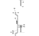
- FIG. 5 is a schematic cross-sectional view showing a temporary holding state.
- FIG. 6 is a schematic side view showing a door in which the service hole cover and the wiring module for the door according to the second embodiment are incorporated.
- FIG. 7 is a schematic cross-sectional view taken along the line VII-VII of FIG.
- FIG. 8 is a schematic side view showing a state in which the service hole cover is temporarily held.
- 9 is a sectional view taken along line IX-IX of FIG.
- the service hole cover or door wiring module of this disclosure is as follows.
- a service hole cover that covers a service hole formed in an inner panel of a vehicle door panel, and is provided so as to project from the cover main body portion that covers the service hole and the cover main body portion toward the inner panel side.
- the hooking portion is provided with a hooking portion, and the hooking portion is a service hole cover that is hooked on the inner panel with at least a part of the service hole open.
- the service hole cover is temporarily held near the service hole by hooking the hooked part on the inner panel. Further, at least a part of the service hole is open with the hooked portion hooked on the inner panel, and this open area can be used as a work area in the service hole. Therefore, the service hole cover can be temporarily held near the service hole while securing the work area in the service hole.
- a wiring passing portion through which a wiring member passes between both sides of the cover main body is formed in the cover main body portion, and the wiring passing portion is next to the hooking portion. It may be formed in.
- the part of the cover body where the hook is provided is held near the inner panel, and the part of the cover body away from the hook is separated from the service hole to open at least a part of the service hole. Is assumed. For this reason, if the wiring passing portion is provided next to the hooking portion, the wiring passing through the wiring passing portion is between the temporary holding state of the service hole cover and the assembled state of the service hole cover on the inner panel.
- the difference in the path length of the members can be reduced. As a result, the extra length of the wiring member can be shortened as much as possible.
- the hooking portion is a base portion protruding from the cover main body portion toward the inside of the vehicle door panel and a position away from the cover main body portion.
- the tip hooking portion includes a tip hooking portion protruding from the base portion to the outer peripheral side of the cover main body portion, and the tip hooking portion is attached to the inner panel from the inside of the vehicle door panel in a state where the base portion is in contact with the edge of the service hole. You may get caught. In this case, the service hole cover is easily temporarily held by the inner panel by hooking the hooked portion on the edge of the service hole.
- the tip hooking portion may be provided at a position away from the inner surface of the inner panel while the service hole cover is attached to the inner panel.
- a gap is created between the inner panel and the service hole cover according to the dimension in which the tip hooking portion is separated from the inner surface of the inner panel. Can be provided. This gap allows at least a portion of the service hole to be opened.
- the hooking portion is a position away from the shaft portion protruding from the cover main body portion toward the inside of the vehicle door panel and the cover main body portion.
- the retaining portion includes a retaining portion that protrudes to the outer peripheral side of the shaft portion, and the retaining portion rotatably penetrates the hole formed in the inner panel, and the retaining portion is inside the vehicle door panel. May be caught on the inner panel.
- the service hole cover is temporarily held by the inner panel by inserting the hooked portion into the hole portion of the inner panel and hooking the hooked portion in the retaining state. In this case, by rotating the service hole cover around the shaft portion, at least a part of the service hole can be opened.
- the retaining portion may be provided at a position away from the inner surface of the inner panel while the service hole cover is attached to the inner panel.
- a gap is created between the inner panel and the service hole cover according to the dimension in which the retaining portion is separated from the inner surface of the inner panel. Can be provided. This gap allows the service hole cover to be easily rotated around the shaft, thereby opening at least a portion of the service hole.
- the cover main body includes a first cover main body that covers the first service hole, a second cover main body that covers the second service hole, and the like.
- a connecting portion connecting the first cover main body portion and the second cover main body portion is included, the shaft portion is provided in the connecting portion, and the first service hole and the second service hole of the inner panel are provided. It may be rotatably inserted into the hole formed between the two.
- the cover main body can rotate around the shaft between the first cover main body and the second cover main body. Therefore, the portion of the first service hole separated from the shaft portion and the portion of the second service hole separated from the shaft portion can be easily opened.
- the service hole cover according to any one of (6) to (8) in a state where the cover main body is rotated around the shaft portion from the mounting posture covering the service hole. Further may be provided with a rotation restricting protrusion that is hooked on the edge. As a result, it is easy to stably maintain a state in which at least a part of the service hole is opened by rotating the cover main body portion from the mounting posture.
- a door wiring module may include a service hole cover according to any one of (1) to (9) and a wiring member held by the service hole cover. This makes it possible to easily attach the wiring member held by the service hole cover to the vehicle door panel by using the service hole while the service hole cover is temporarily held near the service hole.
- FIG. 1 is a schematic side view showing a door 10 in which the service hole cover 40 and the door wiring module 30 according to the first embodiment are incorporated.
- FIG. 2 is a schematic cross-sectional view taken along the line II-II of FIG.
- FIG. 3 is a schematic side view showing the door wiring module 30.
- FIG. 4 is a schematic cross-sectional view taken along the line IV-IV of FIG.
- the wiring member shown by one line may be one wiring member or may be a plurality of wiring members.
- the door 10 is formed in a flat shape as a whole, and is a portion that can be opened and closed so as to partition the inside of the vehicle and the outside of the vehicle in the vehicle.
- the door 10 is assumed to be a driver's seat side door, a passenger's seat side door, a rear seat door, or the like.
- the door 10 includes a vehicle door panel 20, a design trim 16, and a door wiring module 30.
- the vehicle door panel 20 includes an outer panel 21 and an inner panel 22.
- the outer panel 21 is provided on a portion of the door 10 facing the outside of the vehicle.
- the outer panel 21 is a part that constitutes the appearance of the vehicle together with the body body of the vehicle.
- the inner panel 22 is provided on the vehicle interior side with respect to the outer panel 21.
- the inner panel 22 has a side plate portion 23 and a main plate portion 25.
- the side plate portion 23 is a portion that protrudes from the outer panel 21 toward the vehicle interior side.
- the main plate portion 25 is a portion that is connected to the side plate portion 23 and extends along the outer panel 21 while being spaced from the outer panel 21. A space is formed between the outer panel 21, the main plate portion 25, and the side plate portion 23.
- a door device provided on the door 10 is arranged in the space, and a window is housed in the space.
- the main plate portion 25 of the inner panel 22 is provided with a first service hole 26 and a second service hole 27.
- the first service hole 26 and the second service hole 27 are open on both sides of the inner panel 22. Therefore, the worker can access the space in the vehicle door panel 20 through the first service hall 26 or the second service hall 27.
- the operator can work in the space inside the vehicle door panel 20, for example, the work of handling the wiring member, the work of connecting the wiring member to the door device. Etc. can be easily carried out.
- the first service hall 26 and the second service hall 27 are formed apart from each other.
- the first service hole 26 and the second service hole 27 are formed apart from each other in the front-rear direction of the vehicle.
- the first service hole 26 and the second service hole 27 have a size that allows the operator's hand to pass through, for example, a minimum opening width of 10 cm, preferably 15 cm or more.
- the first service hole 26 and the second service hole 27 are formed in a rectangular shape.
- the vertical size of the first service hole 26 is smaller than the vertical size of the second service hole 27.
- the lower edges of the first service hole 26 and the second service hole 27 extend downward toward the rear. At least a portion of the lower edge of the second service hole 27 is located on an extension of at least a portion of the lower edge of the first service hole 26.
- the shapes of the first service hole 26 and the second service hole 27 may be a polygonal shape such as a circular shape or a triangular shape.
- the first service hole 26 may have a larger opening than the second service hole 27, and the first service hole 26 and the second service hole 27 may have an opening of the same size.
- the first service hole 26 is formed at a position closer to the front of the inner panel 22.
- the second service hole 27 is formed at a position closer to the rear of the inner panel 22.
- the second service hole 27 is located behind the vehicle in the front-rear direction at a distance from the first service hole 26.
- the intervening portion 25p is a plate-shaped portion extending along the vertical direction.
- the intervening portion 25p may project to the outside (vehicle interior side) of the inner panel 22.
- the intervening portion 25p may be formed by being curved so as to be convex on the side opposite to the outer panel 21 by, for example, press working.
- a rail may be provided along the groove to support the runner for moving the window up and down.
- the intervening portion 25p may be formed flat or may be formed in a concave shape when viewed from the vehicle interior side.
- the design trim 16 is provided on the portion of the door 10 facing the vehicle interior side and constitutes the interior of the vehicle. For example, an inner handle, an operation unit of an in-vehicle device, and the like are attached to the design trim 16.
- the service hole cover 40 covers the service holes 26 and 27 formed in the inner panel 22 of the vehicle door panel 20.
- the door wiring module 30 has a configuration in which the service hole cover 40 and the wiring member 60 are integrated by holding the wiring member 60 in the service hole cover 40.
- the service hole cover 40 includes a cover main body portion 42 and a hooking portion 50.
- the cover main body portion 42 is a portion that covers the service holes 26 and 27, and is formed in a shape that expands on the side opposite to the outer panel 21 (vehicle interior side) with respect to the inner panel 22.
- the hooking portion 50 is a portion provided so as to project from the cover main body portion 42 toward the inner panel 22 side, more specifically, toward the inside of the vehicle door panel 20.
- Such a service hole cover 40 is a part molded by a resin such as polypropylene (PP).
- the service hole cover 40 may be a part in which molten resin is injected into a mold and injection-molded, or a part in which a non-woven fabric or the like is heated and pressed by a simple mold to be hardened. good.
- the service hole cover 40 may be a component in which a mold-molded cover main body portion 42 and a hook portion 50 formed separately thereof are combined.
- the hooking portion 50 may be fitted and fixed to the cover main body portion 42.
- the cover main body portion 42 may be molded by using the hooked portion 50 as an insert component. Then, the hooking portion 50 can be hooked on the inner panel 22 in a state before the service hole cover 40 is mounted on the inner panel 22. In this state, the service hole cover 40 is held near the service holes 26 and 27 with at least a part of the service holes 26 and 27 open.
- the cover main body 42 is formed in a shape capable of covering the service holes 26, 27 according to the service holes 26, 27 formed in the inner panel 22.
- the cover main body 42 includes a first cover main body 44, a second cover main body 46, and a connecting portion 48.
- the first cover main body 44 is formed in a shape that covers the first service hole 26. More specifically, the first cover main body 44 is a flat resin portion that is the same as or greatly spreads as the first service hole 26. The first cover main body 44 may have a shape that expands in a shape similar to the opening shape of the first service hole 26. The first cover main body 44 is attached so as to close the first service hole 26. Thereby, the service hole cover 40 can partition the inside and the outside of the vehicle.
- the second cover main body 46 is formed in a shape that covers the second service hole 27.
- the second cover main body 46 is a flat resin component that is the same as or wider than the second service hole 27.
- the second cover main body 46 may have a shape that expands in a shape similar to the opening shape of the second service hole 27.
- the role and mounting structure of the second cover main body 46 with respect to the second service hole 27 is the same as the role and mounting structure of the first cover main body 44 with respect to the first service hole 26 described above.
- the attached state is maintained by screwing, locking structure, adhesion and the like.
- the gap between them can be closed as much as possible.
- the portion of the peripheral edge portion of the second cover main body portion 46 that overlaps with the inner panel 22 is adhered to the inner panel 22, the gap between them can be closed as much as possible.
- the first cover main body 44 and the second cover main body 46 are attached to the service holes 26 and 27, so that the first cover main body 44 and the second cover main body 46 are the outer panel 21 and the inner panel. It partitions the passenger compartment side of the space between the vehicle and 22. A window exposed to a rainwater environment is housed in the space, and a slit-shaped opening through which the window enters and exits is formed above the space. Therefore, the space is a space where water may infiltrate. Further, since the space is a space that may be connected to an external space, it is also a space in which wind noise or the like from the outside may invade. Therefore, it is preferable that the first cover main body 44 and the second cover main body 46 are provided together with the inner panel 22 as members that more completely partition the vehicle interior space and the external space.
- the first cover main body portion 44 includes a main cover portion 44a, a frame portion 44b, and a flange portion 44c.
- the main cover portion 44a is a portion that is the same size as or smaller (slightly smaller) than the first service hole 26 and spreads like a plate.
- the frame portion 44b is formed so as to project from the outer edge of the main cover portion 44a toward one main surface side (vehicle interior side) of the main cover portion 44a.
- the flange portion 44c is formed so as to project from the outer edge of the frame portion 44b toward the outer peripheral side.
- the frame portion 44b is formed so as to extend from the main cover portion 44a toward the flange portion 44c to the outside of the main cover portion 44a.
- the main cover 44a With the first cover main body 44 attached to the inner panel 22 where the first service hole 26 is formed, the main cover 44a is inside the first service hole 26 (outer panel 21 rather than the main plate 25).
- the flange portion 44c is disposed on the outside of the first service hole 26 (on the vehicle interior side of the main plate portion 25), and the frame portion 44b connects the two. As a result, the space between the edge portion of the main cover portion 44a and the inner edge portion of the first service hole 26 is closed by the frame portion 44b and the flange portion 44c.
- the second cover main body portion 46 includes a main cover portion 46a, a frame portion 46b, and a flange portion 46c.
- the main cover portion 46a, the frame portion 46b, and the flange portion 46c have the same configuration as the main cover portion 44a, the frame portion 44b, and the flange portion 44c, except that the main cover portion 46a, the frame portion 46b, and the flange portion 46c are configured to match the second service hole 27.
- the connecting portion 48 is a portion that connects the first cover main body portion 44 and the second cover main body portion 46.
- the connecting portion 48 is the trailing edge portion (edge on the side of the second cover main body portion 46) of the first cover main body portion 44 and the leading edge portion (side of the first cover main body portion 44) of the second cover main body portion 46. The edge of) is connected.
- the connecting portion 48 may be a portion extending outward from the flange portions 44c and 46c.
- the connecting portion 48 is, for example, a portion integrally formed with the first cover main body portion 44 and the second cover main body portion 46.
- the connecting portion 48 is a portion that is formed separately from the first cover main body portion 44 and the second cover main body portion and is joined to the first cover main body portion 44 and the second cover main body portion 46 by adhesive, welding, or the like. May be good.
- the dimensions between the front and rear ends of the connecting portion 48 are set to the size corresponding to the distance between the service holes 26 and 27. Therefore, the first cover main body 44 and the second cover main body 46 held by the connecting portion 48 can be easily arranged together with respect to both the service holes 26 and 27. Further, here, the vertical dimension of the connecting portion 48 is set smaller than the vertical dimension of the trailing edge portion of the first cover main body portion 44 and the vertical dimension of the leading edge portion of the second cover main body portion 46. As a result, the first cover main body 44 and the second cover main body 46 are connected with a lightweight material and a small amount of material.
- the connecting portion 48 may be, for example, a portion integrally formed with the first cover main body portion 44 and the second cover main body portion 46.
- the connecting portion 48 is a portion that is formed separately from the first cover main body portion 44 and the second cover main body portion and is joined to the first cover main body portion 44 and the second cover main body portion 46 by adhesive, welding, or the like. May be good.
- first cover main body 44 and the second cover main body 46 are connected and integrated by the connecting portion 48.
- the connecting portion 48 may be omitted, and the first cover main body portion 44 and the second cover main body portion 46 may be configured as separate bodies.
- both the first service hole 26 and the second service hole 27 are provided on the inner panel 22.
- Yet another service hole may be provided in the inner panel 22.
- the inner panel 22 may be provided with only one service hole.
- the cover main body 42 may be formed with wiring passage portions 44h and 46h through which the wiring member 60 passes between both sides of the cover main body 42. By passing the wiring member 60 through the wiring passage portions 44h and 46h, the wiring member 60 can be arranged in both spaces partitioned by the inner panel 22 and the service hole cover 40.
- the wiring passage portions 44h and 46h may be holes penetrating both sides of the first cover main body portion 44 or the second cover main body portion 46.
- the wiring passage portions 44h and 46h may be recesses formed so as to be recessed inward from the edge of the first cover main body portion 44 or the second cover main body portion 46.
- the wiring passage portions 44h and 46h may be formed on the main cover portions 44a and 46a or the frame portions 44b and 46b of the cover main body portions 44 and 46.
- the wiring passage portions 44h and 46h are formed in the frame portions 44b and 46b.
- FIG. 5 shows a state in which at least a part of the service holes 26 and 27 is opened with the hooked portion 50 hooked on the inner panel 22 in the schematic cross section corresponding to FIG.
- the hooking portion 50 is a portion that is hooked on the inner panel 22 with at least a part of the service holes 26 and 27 open.
- the state in which at least a part of the service holes 26 and 27 is open means that at least a part of the service holes 26 and 27 can be used by a worker's hand or a robot hand from the outside of the vehicle door panel 20. It is said that it is open.
- the service hole cover 40 is separated from the service holes 26 and 27, and the inner panel 22 and the service hole cover 40 are used. If a worker's hand or the like can be put into the service halls 26 and 27 through the gap, at least a part of the service halls 26 and 27 is open.
- a plurality of hooking portions 50 are provided. More specifically, the hooking portion 50 is provided on each of the first cover main body portion 44 and the second cover main body portion 46.
- the hooking portion 50 may be formed on the lower side (closer to the center in the vertical direction) of the first cover main body portion 44 and the second cover main body portion 46. Then, in a state where the plurality of hooking portions 50 are hooked on the edges (here, the lower edge) of the service holes 26 and 27, at least a part of the service holes 26 and 27 is opened.
- the number of hooking portions 50 may be one or three or more.
- the service hole cover 40 tilts around the portion where the hooked portion 50 is hooked on the inner panel 22 to open at least a part of the service holes 26 and 27. Therefore, when three or more hooking portions 50 are provided, it is preferable that the three or more hooking portions 50 are provided at positions arranged in a straight line.
- the hooking portion 50 includes a base portion 52 and a tip hooking portion 54.
- the base portion 52 projects from the cover main body portion 42 toward the inside of the vehicle door panel 20.
- the base 52 is a surface of the first cover main body 44 (or the second cover main body 46) facing the inside of the vehicle door panel 20, and is below the first cover main body 44 (or the second cover main body 46). It is projected at a position inside the middle part in the extending direction of the edge.
- the tip hooking portion 54 is a cover main body 42 (first cover main body 44 or second cover 42) from the base 52 at a position D1 away from the cover main body 42 (first cover main body 44 or second cover main body 46). It is formed in a shape protruding toward the outer peripheral side (that is, the flange portions 44c and 46c sides) of the main body portion 46).
- the tip hooking portion 54 is configured to be hooked on the inner panel 22 from the inside of the vehicle door panel 20 in a state where the base portion 52 is in contact with the edges (here, the lower edge) of the service holes 26 and 27 due to its own weight. There is. More specifically, in a state where the hooked portion 50 is hooked on the inner panel 22, the service hole cover 40 is tilted around a portion where the hooked portion 50 is hooked on the inner panel 22. Then, the upper portion of the service hole cover 40 is separated from the inner panel 22 until the lower portion (for example, the lower edge) of the service hole cover 40 below the hooking portion 50 comes into contact with the inner panel 22.
- the hooking portion 50 is in the final assembled state in which the service hole cover 40 is assembled to the inner panel 22 so as to close the service holes 26 and 27, and is not hooked on the inner panel 22. Therefore, in the final assembled state, the tip hooking portion 54 is provided at a position away from the inner surface of the inner panel 22 (the surface facing inward of the vehicle door panel 20) (see FIG. 4). As a result, the service hole cover 40 can be temporarily held at a position away from the inner panel 22 by being caught by the hooking portion 50 with respect to the inner panel 22. Such a configuration helps to open the service holes 26, 27 more widely. Further, in the final assembled state, the base 52 may also be provided at a position away from the edges of the service holes 26 and 27.
- the tip hooking portion 54 may be inclined with respect to the base portion 52 so as to face the base end portion of the base portion 52. That is, as described above, in the state where the hooked portion 50 is hooked on the edges of the service holes 26 and 27, the base portion 52 faces diagonally downward toward the outside away from the edges of the service holes 26 and 27.
- the tip hooking portion 54 is inclined so as to face the base end portion of the base portion 52, the tip hooking portion 54 is in a parallel posture with respect to the inner surface of the inner panel 22 or the tip portion is placed on the inner panel even in the above posture. It becomes easy to maintain the state of being in contact with the inner surface of 22 and it becomes difficult to slip off from the inner panel 22.
- At least one of the wiring passing portions 44h and 46h may be formed next to the hooking portion 50.
- at least one of the wiring passage portions 44h and 46h may be formed next to the hook portion 50 at any of the linear or arcuate edges around the service hole cover 40.
- At least one of the wiring passage portions 44h and 46h is located at a distance of 20 cm or less, preferably at a distance of 10 cm or less, and more preferably at a distance of 5 cm or less with respect to the hooked portion 50. It may be provided at the above position.
- the service hole cover 40 is tilted around the vicinity of the hooked portion by the hooked portion 50 to open at least a part of the service holes 26 and 27.
- the difference in the wiring path of the wiring member 60 passing through the wiring passage portions 44h and 46h is small between the temporary holding state and the final assembly state, the work required for wiring the wiring member 60 is necessary.
- the extra length can be reduced as much as possible. If at least one of the wiring passing portions 44h and 46h is formed next to the hooking portion 50, the extra work length required for the wiring member 60 can be reduced as much as possible.
- the plurality of wiring members 60 connect the door device and the vehicle body device 14 provided on the vehicle body to supply electric power to the door device, or send a signal between the door device and the vehicle body device 14.
- the wiring member 60 may be an electric wire 60.
- As the electric wire 60 a coated electric wire having a coated layer 62 formed around a core wire 61 composed of a conductor can be used (see FIG. 4).
- the core wire 61 may be a single core wire or a stranded wire.
- the type of the electric wire 60 is not particularly limited, and may include a single wire, a composite electric wire, and the like.
- a single wire is an electric wire having one conductive path.
- the composite electric wire is an electric wire having a plurality of conductive paths.
- the composite electric wire may be formed by combining a plurality of single wires, such as a twisted wire or a composite cable.
- the wiring member 60 may include an optical fiber cable or the like.
- one end of the plurality of wiring members 60 extends from the door 10 in a bundled state via a part of the door 10 (the side plate portion 23 on the door hinge side in the example shown in FIG. 1). , Guided inside the car body. It is assumed that one end of the plurality of wiring members 60 is connected to the vehicle body equipment 14 or a relay connector provided at the end of the wiring member extending from the vehicle body equipment via the vehicle body side connector 70 or the like.
- the vehicle body device 14 is not particularly limited, but, for example, an electronic control unit (ECU) or a battery is assumed.
- a grommet 78 may be attached to a portion of the plurality of wiring members 60 extending between the door 10 and the vehicle body. In the example shown in FIG.
- the grommet 78 is a so-called through grommet, and is held in a state of being inserted into a through hole formed in the side plate portion 23. As a result, the infiltration of water through the through hole is suppressed.
- Adhesive tape or the like may be wound around one end of the plurality of wiring members 60.
- An exterior member such as a corrugated tube may be attached to one end of the plurality of wiring members 60.
- the wiring member 60 is guided from the vehicle body through the through hole into the vehicle door panel 20, and passes through the first service hole 26 or the second service hole 27 depending on the position of the door device to be connected to the vehicle.
- An example of being derived to the outside of the door panel 20 is shown.
- the wiring member is arranged along the surface of the inner panel 22 on the passenger compartment side, and passes through the first service hole 26 or the second service hole 27 depending on the position of the door device to be connected. It may be guided into the vehicle door panel 20.
- the through hole is provided in the hinge side portion of the door 10.
- the door 10 may be supported so as to be slidable and openable with respect to the vehicle body.
- the plurality of wiring members 60 extend from the grommet 78 on the way from one end to the other end, branch off, and extend toward the door device to be connected to each.
- connectors 72a, 72b, 72c, 72d, 72e corresponding to the door device to be connected are provided.
- the connectors 72a, 72b, 72c, 72d, 72e are connected to the connectors provided in the door devices 76a, 76b, 76c, 76d, 76e.
- the end of the branch destination of the plurality of wiring members 60 may be directly connected to the door devices 76a, 76b, 76c, 76d, 76e.
- the door device 76a is, for example, a speaker device 76a incorporated in the door 10.
- the speaker device 76a is provided at a position below the first service hole 26 in the inner panel 22.
- the connector on the speaker device 76a side is provided in the internal space of the vehicle door panel 20.
- the wiring member 60a is an electric wire for transmitting an audio signal.
- the door device 76b is, for example, a device provided in the door 10 at a position closer to the front than the center in the front-rear direction.
- the door device 76b is, for example, an electric door mirror 76b.
- the electric door mirror 76b is provided at the front of the door, more specifically, at a position in front of the closed window.
- the electric door mirror 76b incorporates an actuator for changing the direction of the mirror and an actuator for storing and deploying the electric door.
- These actuator-side connectors are provided in the internal space of the vehicle door panel 20.
- the wiring member for a door mirror connected to the electric door mirror 76b via the connector or the like of the wiring member 60 may be referred to as a wiring member 60b. It is assumed that the wiring member 60b is an electric wire that supplies electric power to the actuator.
- the door device 76c is, for example, a device provided at a position of the door 10 behind the center in the front-rear direction.
- the door device 76c is, for example, a door handle device 76c. That is, the door 10 is provided with a handle 76C for opening and closing the door 10.
- the handle 76C is provided so as to be exposed to the outside of the vehicle with respect to the outer panel 21.
- the door handle device 76c is provided on the handle 76C, which is a sensor that detects the opening / closing operation of the key, a sensor that detects the operation of the outer handle, an antenna device that transmits and receives a signal to and from the key side antenna device, and the handle 76C.
- a switch for example, a switch for releasing the door lock according to the authentication result with the wireless communication key
- the connector on the door handle device 76c side is provided on the inner portion of the outer panel 21.
- the door handle wiring member connected to the door handle device 76c via the connector may be referred to as a wiring member 60c. It is assumed that the wiring member 60c is an electric wire that supplies electric power to the door handle device 76c or transmits a signal.
- the door device 76d is, for example, a device provided at a position of the door 10 behind the center in the front-rear direction.
- the door device 76d is, for example, a door lock actuator 76d. That is, a door lock device for locking and unlocking the door 10 is incorporated in the door 10, and the door lock actuator 76d is provided in the door lock device.
- the connector on the door lock actuator 76d side may be provided on the outside (indoor side) of the inner panel 22.
- the door lock wiring member connected to the door lock actuator 76d via the connector may be referred to as a wiring member 60d. It is assumed that the wiring member 60d is an electric wire that supplies electric power to the door lock actuator 76d.
- the door device 76e is, for example, a device provided at a position of the door 10 behind the center in the front-rear direction.
- the door device 76e is, for example, a foot lamp 76e that illuminates the feet when the door 10 is opened.
- the connector on the foot lamp 76e side may be provided on the outside (indoor side) of the inner panel 22.
- the wiring member 60 connected to the foot lamp 76e may be referred to as a wiring member 60e. It is assumed that the wiring member 60e is an electric wire that supplies electric power to the foot lamp 76e.
- the wiring member 60 is connected to the door device provided inside the vehicle door panel 20 with respect to the inner panel 22, or is connected to the door device provided outside the vehicle door panel 20. Therefore, the wiring member 60 is routed inside and outside the inner panel 22 through the service holes 26 and 27. Further, at least a part of the wiring member 60 is arranged in the vehicle door panel 20, and the connector is connected to the door device inside the wiring member 60. Therefore, when the wiring member 60 is attached to the vehicle door panel 20, the work of passing the wiring member 60 through the service holes 26 and 27 and the wiring member 60 being routed in the vehicle door panel 20 as necessary for the vehicle. The work of fixing with the door panel 20 for the vehicle, the work of connecting the connector in the door panel 20 for the vehicle, and the like are performed.
- the door devices 76a, 76b, 76c, 76d, and 76e may be omitted. Further, the positions of the door devices 76a, 76b, 76c, 76d, 76e may be changed according to functional or design convenience.
- the speaker device 76a may be provided near the back of the door 10.
- wireless communication with other door devices such as various switch devices (switches for opening and closing windows, switches for opening and closing door locks, etc.), power receiving antennas that receive power supply from in-vehicle devices in a non-contact manner, and in-vehicle devices. Communication equipment, in-vehicle door handle equipment, and the like may be provided.
- the plurality of wiring members 60 include those corresponding to the door equipment provided on the door 10.
- the wiring member 60 may include a wiring member 60 that is not connected to the vehicle body device but connects the door devices to each other.
- the plurality of wiring members 60 branch according to the door devices 76a, 76b, 76c, 76d, 76e on the way from one end to the other end.
- the wiring member 60a is a portion extending from the grommet 78 in the vehicle door panel 20, and branches from the other wiring members 60b, 60c, 60d, 60e.
- the wiring member 60a is connected to the connector on the speaker device 76a side below the first service hole 26 in the vehicle door panel 20.
- the wiring member 60b is held by the first cover main body 44 so as to face the electric door mirror 76b. That is, the wiring member 60b is guided from the vehicle body device 14 toward the electric door mirror 76b via the first cover main body portion 44.
- the cover body 42 only needs to guide the wiring member 60 toward the door device to be connected. Therefore, the wiring member 60 is located between the cover body 42 and the door device to be connected. You may bend at.
- the wiring member 60b may also be bent between the cover main body portion 42 and the electric door mirror 76b.
- the wiring members 60c, 60d, 60e are held by the second cover main body 46 so as to face the door handle device 76c, the door lock actuator 76d, and the foot lamp 76e. More specifically, the wiring members 60c, 60d, 60e are the door handle device 76c and the door lock actuator from the vehicle body device 14 via the first cover main body 44, the connecting portion 48 and the second cover main body 46. You will be guided toward 76d and the foot lamp 76e. It is not essential that all of the wiring members 60c, 60d, and 60e pass through the first cover main body 44. A part or all of the wiring members 60c, 60d, 60e may be configured to be guided by the second cover main body 46 from the vehicle body device 14 without passing through the first cover main body 44.
- the wiring members 60b, 60c, 60d, 60e are led out from the inside of the vehicle door panel 20 to the outside (indoor side) through the lower wiring passage portion 44h formed in the first cover main body portion 44. Will be done.
- the wiring passage portion 44h is formed in the lower part of the frame portion 44b in the first cover main body portion 44.
- the wiring members 60b, 60c, 60d, 60e extending the grommet 78 branch upward with respect to the wiring member 60a and pass through the wiring passage portion 44h of the first cover main body portion 44. It is guided to the outer surface (inner surface of the vehicle) of the first cover main body 44.
- At least this passing portion holds the wiring members 60b, 60c, 60d, 60e with respect to the first cover main body 44.
- the wiring members 60b, 60c, 60d, 60e may be held along a fixed path with respect to the first cover main body 44.
- the wiring member 60b branches with respect to the wiring members 60c, 60d, 60e, the wiring member 60b faces upward, and the wiring members 60c, 60d, 60e are the second cover main body 46 ( It may be held so as to face backward).
- the route holding structure of the wiring members 60b, 60c, 60d, 60e with respect to the first cover main body 44 has at least a part of the wiring members 60b, 60c, 60d, 60e along a certain path with respect to the first cover main body 44.
- the structure is not particularly limited as long as it can be held.
- the holding mode of the wiring members 60b, 60c, 60d, 60e with respect to the first cover main body 44 may be, for example, a contact portion fixing mode or a non-contact portion fixing mode.
- the contact portion fixing mode is maintained in a fixed state by the portions where the wiring member 60 and the fixing partner come into contact with each other and do not separate from each other.
- the contact site may be indirectly fixed or the contact site may be directly fixed.
- the contact portion indirect fixing means that the wiring member 60 and the fixing partner are indirectly attached and fixed via an intervening member such as an adhesive, an adhesive, or a double-sided adhesive tape provided between them.
- the contact portion direct fixing means that the wiring member 60 and the fixing partner are directly attached to each other and fixed without using an adhesive or the like separately provided. In the direct fixing of the contact portion, it is assumed that, for example, the resin contained in at least one of the wiring member 60 and the fixing partner melts and sticks to the mating side member to be fixed.
- Non-contact site fixation is a fixation mode that is not contact site fixation.
- a sewing thread, another sheet material, an adhesive tape, etc. presses the wiring member 60 toward the fixing partner
- a sewing thread, another sheet material, an adhesive tape, etc. surrounds the wiring member 60 and the fixing partner.
- the wiring member 60 and the fixing partner are sandwiched between the wiring member 60 and the fixing partner to maintain the wiring member 60 and the fixing partner in a fixed state.
- non-contact portion fixing is adopted as a fixing mode of the wiring member 60 to the first cover main body portion 44.
- the wiring member 60 is arranged on one surface of the first cover main body 44, and the sheet-shaped pressing member 90 straddles the wiring member 60 of the first cover main body 44. It is mounted on one side.
- the pressing member 90 may be attached to the first cover main body 44 by an adhesive layer (or an adhesive), an adhesive, welding, or the like. If the pressing member 90 is an adhesive tape, the wiring member 60 is easily held against the service hole cover 40 by attaching the adhesive tape to the service hole cover 40 along the wiring member 60.
- the service hole cover 40 may be formed with a groove along the path of the wiring member 60. In this case, with the wiring member 60 housed in the groove, the pressing member 90 may be attached to the service hole cover 40 so as to straddle the groove. As a result, the misalignment of the wiring member 60 is suppressed.
- the wiring member 60b is held on one surface of the main cover portion 44a of the first cover main body portion 44 along a path from the lower side to the upper side, and passes through the wiring passage portion 44h formed in the upper part of the frame portion 44b to the vehicle. Guided into the door panel 20. Then, the connector 72b at the end of the wiring member 60b is connected to the connector on the electric door mirror 76b side.
- the wiring members 60c, 60d, and 60e are held on one surface of the main cover portion 44a of the first cover main body portion 44 from the lower side to the upper side, branch off from the wiring member 60b in the middle, and are held along the rearward path. It goes beyond the frame portion 44b and the flange portion 44c, and further passes over the connecting portion 48 and heads rearward.
- the wiring members 60c, 60d, 60e are held by the second cover main body 46.
- the same structure as the holding structure in the first cover main body 44 can be applied.
- the wiring members 60c, 60d, and 60e may be held by the connecting portion 48 in the same configuration as in the first cover main body portion 44.
- the wiring members 60c, 60d, 60e are held along a fixed path on one surface of the main cover portion 46a beyond the frame portion 46b and the flange portion 46c at the front portion of the second cover main body portion 46.
- the wiring members 60c, 60d, 60e are directed from the front to the rear along a common path.
- the wiring member 60e branches with respect to the wiring members 60c and 60d and faces downward.
- the wiring member 60c branches to the wiring member 60d and faces upward.
- the wiring member 60d faces rearward as it is.
- the wiring member 60c is guided into the vehicle door panel 20 through the wiring passage portion 46h formed in the upper part of the frame portion 46b in the second cover main body portion 46. Then, the connector 72c at the end of the wiring member 60c is connected to the connector on the door handle device 76c side in the vehicle door panel 20.
- the wiring member 60d goes rearward beyond the rear frame portion 46b and the flange portion 46c, and is connected to the connector on the door lock actuator 76d side outside the vehicle door panel 20.
- the wiring member 60e goes downward beyond the lower frame portion 46b and the flange portion 46c, and is connected to the connector on the foot lamp 76e side outside the vehicle door panel 20.
- the service hole cover 40 When the wiring member 60 is assembled to the vehicle door panel 20, the service hole cover 40 is held against the inner panel 22 by using the hooking portion 50 (see FIG. 5). More specifically, the hooking portion 50 is hooked on the edges of the service holes 26 and 27 of the inner panel 22, and the service hole cover 40 is temporarily held by the inner panel 22 in an oblique posture with respect to the inner panel 22. In this posture, the lower portion of the service hole cover 40 comes into contact with the outward surface (the surface facing the vehicle interior) of the inner panel 22, and the web of the service hole cover 40 is separated from the inner panel 22.
- the operator's hand or the robot hand can perform the wiring work of the wiring member 60 through the openings of the service holes 26 and 27. It can be carried out.
- the wiring work includes passing the wiring member 60 through the service holes 26 and 27, arranging the wiring member 60 in the space inside the vehicle door panel 20, and fixing the wiring member 60 in the space as necessary. Work such as connecting a connector to a door device inside is assumed. At this time, when the wiring member 60 is held by the service hole cover 40, the work of assembling the wiring member 60 held via the service hole cover 40 near the service holes 26 and 27 to the vehicle door panel 20 is performed. It can be easily carried out.
- the service hole cover 40 is temporarily held near the service holes 26 and 27 by the hooking portion 50 being hooked on the inner panel 22. Further, in a state where the hooked portion 50 is hooked on the inner panel 22, at least a part of the service holes 26 and 27 is open, and this opened area can be used as a work area in the service holes 26 and 27. can. Therefore, the service hole cover 40 can be temporarily held near the service holes 26 and 27 while securing the work area in the service holes 26 and 27. In this state, the work of assembling the wiring member 60 to the vehicle door panel 20 can be easily performed.
- the temporary holding state of the service hole cover 40 and the final assembly state of the service hole cover 40 to the inner panel 22 are obtained. It is possible to reduce the path length difference of the wiring member 60 passing through the wiring passage portions 44h and 46h. As a result, the extra length of the wiring member 60 can be reduced as much as possible.
- the hooking portion 50 can be hooked on the edges of the service holes 26 and 27, the service hole cover 40 can be easily held by the inner panel 22 without providing a special hole for hooking on the inner panel 22. Will be done.
- the tip hooking portion 54 is separated from the inner surface of the inner panel 22.
- the hooking portion 50 can be hooked on the inner panel 22 while providing a gap between the inner panel 22 and the service hole cover 40 according to the separated dimension D1. Using this gap, at least a part of the service holes 26 and 27 can be opened as much as possible by tilting the service hole cover 40 with respect to the inner panel 22.
- the service hole cover 40 is provided with a plurality of hooking portions 50, and at least a part of the service holes 26 and 27 is opened in a state where the plurality of hooking portions 50 are hooked on the edges of the service holes 26 and 27.
- the temporary holding state of the service hole cover 40 becomes stable.
- the wiring member 60 is held by the service hole cover 40, the work of assembling the wiring member 60 into the vehicle door panel 20 while holding a part of the wiring member 60 near the service holes 26 and 27. Etc. can be easily carried out.
- the hooking portion 50 does not need to be hooked on the edges of the service holes 26 and 27.
- a hole for temporary holding or a U-shaped rod-shaped receiving portion may be formed in the inner panel 22, and the hooking portion 50 may be hooked on the receiving portion.
- FIG. 6 is a schematic side view showing the door 110 in which the service hole cover 140 and the door wiring module 130 according to the second embodiment are incorporated.
- FIG. 7 is a schematic cross-sectional view taken along the line VII-VII of FIG.
- FIG. 8 is a schematic side view showing a state in which the service hole cover 140 is temporarily held.
- 9 is a sectional view taken along line IX-IX of FIG.
- the same components as those described in the first embodiment are designated by the same reference numerals, the description thereof will be omitted, and the differences from the first embodiment will be mainly described.
- the hooking portion 150 includes a shaft portion 152 and a retaining portion 154.
- the shaft portion 152 is formed so as to project from the cover main body portion 42 of the service hole cover 140 toward the inside of the vehicle door panel 20.
- the shaft portion 152 may be columnar or polygonal.
- the retaining portion 154 projects toward the outer peripheral side of the shaft portion 152 at a position away from the cover main body portion 42. Then, in a state where the shaft portion 152 penetrates the hole portion 22h formed in the inner panel 22, the retaining portion 154 is hooked on the inner panel 22 from the inside of the vehicle door panel 20.
- the retaining portion 154 may include, for example, a pair of elastic pieces 154a that incline outward from the tip end portion of the shaft portion 152 toward the base end side of the shaft portion 152.
- the pair of elastic pieces 154a can be elastically deformed so as to come into contact with the edge of the hole portion 22h and easily approach the shaft portion 152 side. Then, when the hooked portion 150 is further inserted into the hole portion 22h and the pair of elastic pieces 154a exceeds the hole portion 22h, the pair of elastic pieces 154a elastically return to the original shape.
- the tip portions of the pair of elastic pieces 154a can be hooked on the inner panel 22 in a retaining shape at the peripheral edge portion of the hole portion 22h.
- the configuration of the retaining portion 154 is not limited to the above example.
- the retaining portion is formed in an annular shape slightly larger than the inner diameter of the hole portion 22h, and the hole portion 22h is pulled out by elastic deformation of at least one of the retaining portion and the inner panel 22 to prevent the hole portion 22h from coming off. It may be configured to be hooked in a shape.
- the hooking portion 150 may be a portion integrally molded with the cover main body portion 42, or a member formed separately from the cover main body portion 42 is the cover main body portion 42. It may be a member combined with.
- the retaining portion 154 may be provided at a position separated from the inner surface (the surface on the outer panel 21 side) of the inner panel 22 by a distance D2. That is, like the hooking portion 50, the hooking portion 150 does not have to be hooked on the inner panel 22 in the final assembled state and is not used for fixing purposes. In this case, the service hole cover 140 is separated from the inner panel 22 in a state where the retaining portion 154 is in contact with the inner surface of the inner panel 22. Therefore, the service hole cover 140 can easily rotate away from the inner panel 22.
- the shaft portion 152 may be provided at any position of the cover main body portion 42.
- the shaft portion 152 may be provided on the connecting portion 48.
- the shaft portion 152 may be rotatably inserted into the hole portion 22h formed between the first service hole 26 and the second service hole 27 in the inner panel 22.
- each of the first cover main body 44 and the second cover main body 46 can be rotated around the shaft 152 on both sides of the shaft 152. Therefore, the portion of each of the service holes 26 and 27 that is separated from the shaft portion 152 can be easily opened.
- the service hole cover 140 may be provided with a rotation regulation protrusion 160 (see FIGS. 8 and 9).
- the rotation regulation protrusion 160 is formed on the edge of the service holes 26, 27 (here, the service hole 27) in a state where the cover main body 42 is rotated around the shaft portion 152 from the final mounting posture covering the service holes 26, 27. It is the part that gets caught.
- the rotation regulation protrusion 160 is formed on the second cover main body 46.
- the rotation regulation protrusion 160 contacts the service hole 27 in a state where the service hole cover 140 is rotated until the service holes 26 and 27 are opened to an extent suitable for work.
- the rotation restricting protrusion 160 is formed at a position separated above the lower edge of the second cover main body 46.
- the rotation regulation protrusion 160 preferably includes a portion that contacts the edge of the service hole 27 from the inside of the service hole 27, and a portion that contacts the edge of the service hole 27 from the inside of the vehicle door panel 20.
- the rotation restricting protrusion 160 includes a groove portion 162g that opens downward.
- the groove portion 162g is formed in a shape into which the edge of the service hole 27 can be fitted.
- the rotation of the service hole cover 140 is restricted with the edge of the service hole 27 fitted in the groove portion 162 g.
- the position of the service hole cover 140 is restricted in the thickness direction of the inner panel 22. Therefore, the service hole cover 140 rotates about the shaft portion 152, and the temporary holding state in which at least a part of the service holes 26 and 27 is opened is stabilized. It is not essential that the groove portion 162g is formed in the rotation regulation protrusion 160.
- the rotation regulation protrusion 160 may be omitted.
- the service hole cover 140 When the wiring member 60 is assembled to the vehicle door panel 20, the service hole cover 140 is held against the inner panel 22 by using the hooking portion 150 (see FIG. 8). More specifically, the service hole cover 140 is rotated around the shaft portion 152 in a state where the hooked portion is inserted into the hole portion 22h and the retaining portion 154 is prevented from coming off by the inner panel 22.
- the service hole cover 40 is rotated around the shaft portion 152 so that the second cover main body 46, which is larger and heavier than the first cover main body 44, is located below the first cover main body 44. The cover. Then, the service hole cover 140 is temporarily held in a state where the rotation regulation protrusion 160 is in contact with the edges of the service holes 26 and 27.
- the service hole cover 140 is rotated around the shaft portion 152 so as to separate the rotation regulation protrusion 160 from the service hole 27. Then, the first service hole 26 is covered with the first cover main body 44, and the second service hole 27 is covered with the second cover main body 46. After that, with the shaft portion 152 inserted in the hole portion 22h, the hooking portion 150 is further pushed into the hole portion 22h to attach the service hole cover 140 to the inner panel 22. In the final mounting state, the positions of the hooked portion 150 and the hole portion 22h may not match. In this case, the hooked portion 150 may be pulled out from the hole portion 22h.
- the service hole cover 140 is temporarily held by the inner panel 22 by being caught in the retaining state inserted in the hole portion 22h. Therefore, by rotating the service hole cover 140 around the shaft portion 152, at least a part of the service holes 26 and 27 can be opened. As a result, the wiring member 60 can be easily assembled to the vehicle door panel 20 as in the first embodiment.
- the wiring passing portion may be provided next to the hooking portion 150.
- the extra length of the wiring member required for the work can be shortened as much as possible.
- a gap is provided between the inner panel 22 and the service hole cover 140. Can be done. This gap allows the service hole cover 140 to be easily rotated around the shaft portion 152. As a result, at least a part of the service holes 26 and 27 can be easily opened.
- both the cover main body portions 44 and 46 are connected to the shaft portion 152 between them. Can rotate around. As a result, the portion of the service holes 26 and 27 that is separated from the shaft portion 152 can be easily opened.
- the service hole cover 140 includes the rotation regulation protrusion 160, the cover main body portion 42 is rotated from the mounting posture, and at least a part of the service holes 26 and 27 is stably maintained.
- the wiring member 60 since the wiring member 60 is held in the service hole cover 140, the wiring member 60 can be easily assembled to the vehicle door panel 20 in a state where the wiring member 60 is held near the service holes 26 and 27.
Landscapes
- Engineering & Computer Science (AREA)
- Mechanical Engineering (AREA)
- Architecture (AREA)
- Civil Engineering (AREA)
- Structural Engineering (AREA)
- Details Of Indoor Wiring (AREA)
- Installation Of Indoor Wiring (AREA)
- Lock And Its Accessories (AREA)
- Vehicle Interior And Exterior Ornaments, Soundproofing, And Insulation (AREA)
- Superstructure Of Vehicle (AREA)
Priority Applications (2)
| Application Number | Priority Date | Filing Date | Title |
|---|---|---|---|
| CN202180070492.XA CN116349099A (zh) | 2020-10-19 | 2021-10-05 | 检修孔盖及车门用配线模块 |
| US18/031,531 US12240301B2 (en) | 2020-10-19 | 2021-10-05 | Service hole cover and door wiring module |
Applications Claiming Priority (2)
| Application Number | Priority Date | Filing Date | Title |
|---|---|---|---|
| JP2020175114A JP7375724B2 (ja) | 2020-10-19 | 2020-10-19 | サービスホールカバー及びドア用配線モジュール |
| JP2020-175114 | 2020-10-19 |
Publications (1)
| Publication Number | Publication Date |
|---|---|
| WO2022085436A1 true WO2022085436A1 (ja) | 2022-04-28 |
Family
ID=81289649
Family Applications (1)
| Application Number | Title | Priority Date | Filing Date |
|---|---|---|---|
| PCT/JP2021/036813 Ceased WO2022085436A1 (ja) | 2020-10-19 | 2021-10-05 | サービスホールカバー及びドア用配線モジュール |
Country Status (4)
| Country | Link |
|---|---|
| US (1) | US12240301B2 (https=) |
| JP (1) | JP7375724B2 (https=) |
| CN (1) | CN116349099A (https=) |
| WO (1) | WO2022085436A1 (https=) |
Families Citing this family (1)
| Publication number | Priority date | Publication date | Assignee | Title |
|---|---|---|---|---|
| US12280724B2 (en) * | 2023-04-28 | 2025-04-22 | Nishikawa Rubber Co., Ltd. | Routing structure of wire harness of sensor for door of automobile |
Citations (3)
| Publication number | Priority date | Publication date | Assignee | Title |
|---|---|---|---|---|
| JPH09147629A (ja) * | 1995-11-29 | 1997-06-06 | Kansei Corp | 自動車用ワイヤーハーネス装置 |
| JPH09169214A (ja) * | 1995-12-21 | 1997-06-30 | Yazaki Corp | 自動車のドア用部品の取付構造 |
| JP2020083075A (ja) * | 2018-11-26 | 2020-06-04 | 株式会社オートネットワーク技術研究所 | ドア用配線モジュール |
Family Cites Families (5)
| Publication number | Priority date | Publication date | Assignee | Title |
|---|---|---|---|---|
| US5884434A (en) * | 1998-06-12 | 1999-03-23 | General Motors Corporation | Door handle to latch rod connection |
| US6381906B1 (en) * | 1999-11-03 | 2002-05-07 | The Budd Company | Modular door with attachment mechanism |
| DE202006011032U1 (de) | 2006-07-14 | 2007-12-06 | Brose Fahrzeugteile Gmbh & Co. Kommanditgesellschaft, Coburg | Türmodulträger für Kraftfahrzeuge sowie Fahrzeugtür |
| US8020921B2 (en) * | 2009-08-17 | 2011-09-20 | Toyota Motor Engineering & Manufacturing North America, Inc. | Door trim panel having temporary support and pivot members and method of installing the door trim panel |
| JP5900407B2 (ja) * | 2012-11-08 | 2016-04-06 | 住友電装株式会社 | ワイヤハーネス |
-
2020
- 2020-10-19 JP JP2020175114A patent/JP7375724B2/ja active Active
-
2021
- 2021-10-05 WO PCT/JP2021/036813 patent/WO2022085436A1/ja not_active Ceased
- 2021-10-05 US US18/031,531 patent/US12240301B2/en active Active
- 2021-10-05 CN CN202180070492.XA patent/CN116349099A/zh active Pending
Patent Citations (3)
| Publication number | Priority date | Publication date | Assignee | Title |
|---|---|---|---|---|
| JPH09147629A (ja) * | 1995-11-29 | 1997-06-06 | Kansei Corp | 自動車用ワイヤーハーネス装置 |
| JPH09169214A (ja) * | 1995-12-21 | 1997-06-30 | Yazaki Corp | 自動車のドア用部品の取付構造 |
| JP2020083075A (ja) * | 2018-11-26 | 2020-06-04 | 株式会社オートネットワーク技術研究所 | ドア用配線モジュール |
Also Published As
| Publication number | Publication date |
|---|---|
| US20230382201A1 (en) | 2023-11-30 |
| JP7375724B2 (ja) | 2023-11-08 |
| CN116349099A (zh) | 2023-06-27 |
| US12240301B2 (en) | 2025-03-04 |
| JP2022066649A (ja) | 2022-05-02 |
Similar Documents
| Publication | Publication Date | Title |
|---|---|---|
| US6857688B2 (en) | Integrated door module | |
| WO2020110631A1 (ja) | ドア用配線モジュール | |
| JP7552820B2 (ja) | 配線モジュール | |
| JP2015071333A (ja) | ドア用ワイヤーハーネスモジュール | |
| JP2019025921A (ja) | 乗物用内装材に対する電気部品の組付構造 | |
| CN113015656A (zh) | 门用配线模块 | |
| US12049177B2 (en) | Door wiring module and method of manufacturing door wiring module | |
| WO2022085436A1 (ja) | サービスホールカバー及びドア用配線モジュール | |
| CN116195151B (zh) | 门用配线模块和门用配线模块的组装构造 | |
| US20030098614A1 (en) | Conductive interior liner for a vehicle | |
| JPH09121422A (ja) | プロテクタ | |
| JP3293744B2 (ja) | ドア用回路体の組付構造 | |
| JP7375726B2 (ja) | ドア用配線モジュール及び複合サービスホールカバー | |
| WO2022085435A1 (ja) | ドア用配線モジュール | |
| JPH082348A (ja) | 車両用ドアハーネス配索構造 | |
| CN117440904A (zh) | 门用布线模块和门用面状部件 | |
| JP3711087B2 (ja) | プロテクタの取付構造 | |
| CN113439042A (zh) | 车门用配线模块 | |
| CN115279626B (zh) | 配线模块及附带保持构件的配线构件 | |
| JP2022067362A (ja) | ドア用配線モジュール、サービスホールカバー及びドア用配線モジュールの製造方法 | |
| JP2602673Y2 (ja) | ドア用ワイヤーハーネス装置 | |
| JPH09147629A (ja) | 自動車用ワイヤーハーネス装置 | |
| JP2003333724A (ja) | プロテクタ | |
| JP2008279907A (ja) | フロアカーペットの固定構造 |
Legal Events
| Date | Code | Title | Description |
|---|---|---|---|
| 121 | Ep: the epo has been informed by wipo that ep was designated in this application |
Ref document number: 21882577 Country of ref document: EP Kind code of ref document: A1 |
|
| WWE | Wipo information: entry into national phase |
Ref document number: 18031531 Country of ref document: US |
|
| NENP | Non-entry into the national phase |
Ref country code: DE |
|
| 122 | Ep: pct application non-entry in european phase |
Ref document number: 21882577 Country of ref document: EP Kind code of ref document: A1 |
|
| WWG | Wipo information: grant in national office |
Ref document number: 18031531 Country of ref document: US |