WO2022085185A1 - 個体識別装置 - Google Patents
個体識別装置 Download PDFInfo
- Publication number
- WO2022085185A1 WO2022085185A1 PCT/JP2020/039926 JP2020039926W WO2022085185A1 WO 2022085185 A1 WO2022085185 A1 WO 2022085185A1 JP 2020039926 W JP2020039926 W JP 2020039926W WO 2022085185 A1 WO2022085185 A1 WO 2022085185A1
- Authority
- WO
- WIPO (PCT)
- Prior art keywords
- image
- collation
- product
- registered
- camera
- Prior art date
- Legal status (The legal status is an assumption and is not a legal conclusion. Google has not performed a legal analysis and makes no representation as to the accuracy of the status listed.)
- Ceased
Links
Images




Classifications
-
- G—PHYSICS
- G06—COMPUTING OR CALCULATING; COUNTING
- G06V—IMAGE OR VIDEO RECOGNITION OR UNDERSTANDING
- G06V10/00—Arrangements for image or video recognition or understanding
- G06V10/70—Arrangements for image or video recognition or understanding using pattern recognition or machine learning
- G06V10/74—Image or video pattern matching; Proximity measures in feature spaces
- G06V10/75—Organisation of the matching processes, e.g. simultaneous or sequential comparisons of image or video features; Coarse-fine approaches, e.g. multi-scale approaches; using context analysis; Selection of dictionaries
- G06V10/751—Comparing pixel values or logical combinations thereof, or feature values having positional relevance, e.g. template matching
-
- G—PHYSICS
- G06—COMPUTING OR CALCULATING; COUNTING
- G06T—IMAGE DATA PROCESSING OR GENERATION, IN GENERAL
- G06T7/00—Image analysis
- G06T7/0002—Inspection of images, e.g. flaw detection
- G06T7/0004—Industrial image inspection
- G06T7/001—Industrial image inspection using an image reference approach
-
- G—PHYSICS
- G06—COMPUTING OR CALCULATING; COUNTING
- G06V—IMAGE OR VIDEO RECOGNITION OR UNDERSTANDING
- G06V10/00—Arrangements for image or video recognition or understanding
- G06V10/70—Arrangements for image or video recognition or understanding using pattern recognition or machine learning
- G06V10/74—Image or video pattern matching; Proximity measures in feature spaces
-
- G—PHYSICS
- G06—COMPUTING OR CALCULATING; COUNTING
- G06V—IMAGE OR VIDEO RECOGNITION OR UNDERSTANDING
- G06V20/00—Scenes; Scene-specific elements
- G06V20/60—Type of objects
-
- H—ELECTRICITY
- H04—ELECTRIC COMMUNICATION TECHNIQUE
- H04N—PICTORIAL COMMUNICATION, e.g. TELEVISION
- H04N23/00—Cameras or camera modules comprising electronic image sensors; Control thereof
- H04N23/60—Control of cameras or camera modules
- H04N23/61—Control of cameras or camera modules based on recognised objects
-
- H—ELECTRICITY
- H04—ELECTRIC COMMUNICATION TECHNIQUE
- H04N—PICTORIAL COMMUNICATION, e.g. TELEVISION
- H04N23/00—Cameras or camera modules comprising electronic image sensors; Control thereof
- H04N23/60—Control of cameras or camera modules
- H04N23/695—Control of camera direction for changing a field of view, e.g. pan, tilt or based on tracking of objects
-
- G—PHYSICS
- G06—COMPUTING OR CALCULATING; COUNTING
- G06T—IMAGE DATA PROCESSING OR GENERATION, IN GENERAL
- G06T2207/00—Indexing scheme for image analysis or image enhancement
- G06T2207/30—Subject of image; Context of image processing
- G06T2207/30108—Industrial image inspection
- G06T2207/30141—Printed circuit board [PCB]
-
- G—PHYSICS
- G06—COMPUTING OR CALCULATING; COUNTING
- G06V—IMAGE OR VIDEO RECOGNITION OR UNDERSTANDING
- G06V2201/00—Indexing scheme relating to image or video recognition or understanding
- G06V2201/06—Recognition of objects for industrial automation
-
- G—PHYSICS
- G06—COMPUTING OR CALCULATING; COUNTING
- G06V—IMAGE OR VIDEO RECOGNITION OR UNDERSTANDING
- G06V2201/00—Indexing scheme relating to image or video recognition or understanding
- G06V2201/09—Recognition of logos
-
- H—ELECTRICITY
- H04—ELECTRIC COMMUNICATION TECHNIQUE
- H04N—PICTORIAL COMMUNICATION, e.g. TELEVISION
- H04N23/00—Cameras or camera modules comprising electronic image sensors; Control thereof
- H04N23/60—Control of cameras or camera modules
- H04N23/66—Remote control of cameras or camera parts, e.g. by remote control devices
Definitions
- the present invention relates to an individual identification device, an individual identification method, and a recording medium.
- Patent Document 1 describes the following techniques (hereinafter referred to as related techniques).
- the first related technology when the matching area of the matching target object is photographed, the position of the camera of the mobile terminal so that the matching area of the matching target object can be photographed between mobile terminals of different models under the same shooting conditions.
- the reference images for each mobile terminal for controlling the posture the reference image corresponding to the own terminal is acquired.
- the related technique by superimposing the reference image on the through image displayed on the display unit, the collation area of the collation target object can be photographed between mobile terminals of different models under the same imaging conditions. Support people.
- the collation image captured in the collation area of the collation target object captured in this way is collated with the registered image captured in the collation area of the registration target object captured and stored in advance, and the individual is identified.
- the above-mentioned related technique it is possible to obtain a collation image taken by the collation area of the collation target object under predetermined shooting conditions.
- it is difficult to positively match the shooting conditions of the collated image with the shooting conditions of the registered image. The reason is that it is difficult to match the reference image to the matching area when there is no logo that serves as a guide for the matching area, and the matching image is shot under predetermined shooting conditions. Even if it is done, the registered image is not always taken under the same shooting conditions as the collation image.
- the present invention is to provide an individual identification device that solves the above-mentioned problem, that is, it is difficult to positively match the shooting conditions of a collated image with the shooting conditions of a registered image.
- the individual identification device is A setting means for setting shooting conditions when shooting an object collation area with a camera, and An acquisition means for acquiring a collation image, which is an image taken by the camera of the collation area of the object, A collation means for collating the collation image with a registered image which is an image of a collation area of a pre-registered object. While changing the shooting conditions set by the setting means, the process of acquiring the collated image by the acquiring means and the process of collating the collated image with the registered image by the collating means are repeated to obtain the collated image.
- the collation means includes a control means for determining a shooting condition in which the degree of matching with the registered image is equal to or higher than a preset threshold value, and the collation means is based on the collation image shot under the determined shooting condition. It is configured to identify an individual.
- the individual identification method is While changing the shooting conditions when the collation area of the object is photographed by the camera, the image of the collation image which is the image of the collation area of the object and the image of the collation area of the collation image and the object registered in advance. Repeated matching with the registered image, Determine the shooting conditions so that the degree of matching between the collated image and the registered image is equal to or higher than the preset threshold value. Identifying an individual based on collated images taken under the determined shooting conditions, It is configured as follows.
- the program according to one embodiment of the present invention is On the computer While changing the shooting conditions when the collation area of the object is photographed by the camera, the image of the collation image which is the image of the collation area of the object and the image of the collation area of the collation image and the object registered in advance.
- the present invention has the above-mentioned configuration, so that the shooting conditions of the collated image can be positively matched with the shooting conditions of the registered image.
- FIG. 1 is a block diagram of an individual identification system 10 according to a first embodiment of the present invention.
- the individual identification system 10 includes an individual identification device 100 and a production line 200.
- the production line 200 is a line for producing industrial products.
- the industrial products to be produced are not particularly limited.
- the industrial product may be an electric product such as a printed wiring board, a food product such as canned beer, a pharmaceutical product such as a medicine, or the like.
- the production line 200 includes at least two process processing devices, that is, a first process processing device 201 and a second process processing device 202, and conveyors 203 to 205 such as a conveyor.
- the first process processing device 201 is, for example, a solder printing machine that applies solder onto the board
- the second process processing device 202 is a solder printing machine after solder printing.
- the first process processing device 201 is a component mounting machine
- the second process processing device 202 reflows the substrate to melt and harden the solder in a constant temperature bath in order to fix the mounted components to the substrate. It may be a machine.
- the transport machines 203 to 205 are means for transporting products one by one from the upstream side to the downstream side in the order of the first process processing device 201 and the second process processing device 202.
- the production line 200 has at least two phases, an adjustment phase and an operation phase.
- the adjustment phase is carried out prior to the operation phase, and processing such as adjustment of the camera position, which will be described later, is carried out.
- a process of producing a large number of products by an assembly line method is carried out.
- the plurality of products that have passed through the first process processing device 201 are then carried into the second process processing device 202.
- a buffer unit for temporarily storing a plurality of products in no particular order may be provided between the first process processing device 201 and the second process processing device 202. Therefore, the plurality of products that have passed through the first process processing device 201 do not necessarily pass through the second process processing device 202 while maintaining the passing order. Therefore, individual identification is performed to identify which product has passed through the first process processing device 201 and the product carried into the second process processing device 202 is the same.
- the individual identification device 100 is an information processing device that manages individual products produced on the production line 200 for manufacturing process control, quality control, shipping control, sales control, and the like.
- the individual identification device 100 and the first process processing device 201 and the second process processing device 202 are connected to each other so as to be communicable with each other by wire or wirelessly.
- the first process processing device 201 and the second process processing device 202 are used to photograph predetermined parts of the products 241 and 242 carried into the first process processing device 201 and the second process processing device 202 for individual identification.
- Cameras 211 and 212, camera position adjusters 221 and 222 for adjusting the positions of the cameras 211 and 212, and illuminators 231 and 232 for illuminating the product with lighting for photography are provided.
- the cameras 211 and 212 may be, for example, a visible light and color camera equipped with a CCD (Chaul Coupled Device) image sensor or a CMOS (Complementary MOS) image sensor having a pixel capacity of about several million pixels.
- the camera position adjusters 221, 222 may be, for example, a ball screw actuator, a robot arm, or the like.
- the illuminators 231 and 232 may be, for example, ring illuminators.
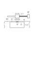
- FIG. 2 is a plan view showing an example of the relative positional relationship between the camera 211 and the product 241 when the product is photographed in the first process processing device 201.
- the camera 211 is placed at a position where the side surface of the product 241 can be photographed from the front.
- the position of the camera 211 can be adjusted by the camera position adjuster 221 in the left direction of the paper surface (upstream direction of the production line) and the right direction of the paper surface (downstream direction of the production line).
- the transport is temporarily stopped when the tip of the product 241 reaches a predetermined position X1, and the product 241 is put into a stationary state.
- the camera 211 photographs the side surface of the product 241 in a stationary state from the front. At this time, as shown in FIG. 3, the camera 211 acquires a registered image which is an image taken with a product side surface portion having a width W separated by a distance L1 from the tip of the product 241 as a collation area. Then, the camera 211 is adjusted to a camera position where such an image of the side surface portion of the product can be taken, and then the position is fixed.
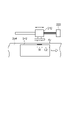
- FIG. 4 is a plan view showing an example of the relative positional relationship between the camera 212 and the product 242 when the product is photographed in the second process processing device 202.
- the camera 212 is placed at a position where the side surface of the product 242 can be photographed from the front.
- the position of the camera 212 can be adjusted in the left-right direction (upstream / downstream direction of the production line) of the paper surface by the camera position adjuster 222.
- the transport is temporarily stopped when the tip of the product 242 reaches the predetermined position X2, and the product 242 is put into a stationary state.
- the camera 212 photographs the side surface of the product 242 in a stationary state from the front.
- the camera 212 is adjusted to a camera position where the same product side surface portion as the registered image, that is, an image of the product side surface portion having a width W separated from the tip of the product 242 by a distance L1 can be captured as a collation image.
- the collation image taken by the camera 212 in the second process processing device 202 and the camera 211 in the first process processing device 201 may be misaligned with the registered image taken in.
- the amount of movement given to the camera position adjuster 221 with respect to the camera position adjuster 222 in order to adjust the position of the camera 212 of the second process processing device 202 to the same position as the camera 211 of the first process processing device 201 Even if the same amount of movement is given, the camera position adjusters 221 and 222 may not actually be adjusted to the same position due to individual differences. Then, as shown in FIG.
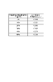
- FIG. 6 is a diagram showing an example of the relationship between the positional deviation between the registered image and the collation image and the average collation score of the same individual, which was created based on the result of the experiment by the present inventor.
- the number of individuals used in the experiment is 1000, and the range of the collation score is 0 to 1 (1 is the highest score).
- the average collation score of the same individual when there is no misalignment is 0.836.
- misalignment occurs, the average collation score of the same individual decreases as the amount of misalignment increases.
- the collation score with the collation image taken by the second process processing device 202 for the same product as the registered image of the product photographed by the first process processing device 201 is the position between the registered image and the collation image. Focusing on the fact that the smaller the deviation, the better, the position of the camera 212 of the second process processing device 202 is adjusted so as to maximize the collation score or to exceed a preset threshold value.
- the individual identification device 100 will be described in detail.
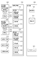
- FIG. 7 is a block diagram of the individual identification device 100.
- the individual identification device 100 is communicably connected to the first process processing device 201 and the second process processing device 202. Further, the individual identification device 100 includes a communication I / F (interface) unit 110, an operation input unit 120, a screen display unit 130, a storage unit 140, and an arithmetic processing unit 150.
- I / F interface
- the communication I / F unit 110 is composed of a data communication circuit, and is configured to perform data communication with an external device wirelessly or by wire.
- the operation input unit 120 is composed of devices such as a keyboard and a mouse, and is configured to detect an operator's operation and output it to the arithmetic processing unit 150.
- the screen display unit 130 is composed of a device such as an LCD (Liquid Crystal Display), and is configured to display various information on the screen in response to an instruction from the arithmetic processing unit 150.
- the storage unit 140 is composed of a storage device such as a hard disk or a memory, and is configured to store processing information and a program 141 required for various processes in the arithmetic processing unit 150.
- the program 141 is a program that realizes various processing units by being read and executed by the arithmetic processing unit 150, and is transmitted from an external device or recording medium (not shown) via a data input / output function such as a communication I / F unit 110. It is read in advance and stored in the storage unit 140.
- the main processing information stored in the storage unit 140 includes the reference image 142 and the product DB (database) 143.
- the reference image 142 is a product for position adjustment (hereinafter referred to as a reference product) carried into the first process processing apparatus 201 by the position-adjusted camera 211, and has a width W separated by a distance L1 from the tip of the reference product. It is an image taken with the side part of the product as a collation area.
- the reference product is one of a plurality of products produced on the production line 200. As with other products produced on the production line 200, the reference product may be subjected to predetermined steps in the first process processing device 201 and the second process processing device 202, or these steps may be omitted. ..
- the product DB 143 is a database that stores information such as images of individual products mass-produced on the production line 200.
- FIG. 8 shows a configuration example of the product DB 143.
- the product DB 143 of this example is composed of a plurality of entries, and one entry is composed of each item of the product ID, the manufacturing information and the registered image of the first step, and the manufacturing information and the collation image of the second step.
- an ID such as a serial number assigned to the product is set.
- the items of the manufacturing information and registered image of the first process are the manufacturing information consisting of the work history of the first process for the product, the type of parts used, the lot number, etc., and the image of the product taken by the camera 211. A certain registered image is set.
- the items of the manufacturing information and collation image of the second process are the manufacturing information consisting of the work history of the second process for the product, the type of parts used, the lot number, etc., and the image of the product taken by the camera 212.
- a collation image is set.
- the arithmetic processing unit 150 has a processor such as an MPU and its peripheral circuits, and by reading and executing the program 141 from the storage unit 140, the hardware and the program 141 cooperate to realize various processing units. It is configured as follows.
- the main processing units realized by the arithmetic processing unit 150 are the registration unit 151 and the collation unit 152.
- the registration unit 151 is configured to acquire an image of the reference product carried into the first process processing device 201 and store it in the storage unit 140 as the reference image 142 in the adjustment phase of the production line 200. Further, the registration unit 151 is configured to acquire an image of a product carried into the first process processing apparatus 201 and store it in the product DB 143 in the operation phase of the production line 200.
- the registration unit 151 includes a shooting condition setting unit 1511, a registered image acquisition unit 1512, a storage unit 1513, and a control unit 1514.
- the shooting condition setting unit 1511 adjusts the position of the camera 211 of the first process processing device 201 by the camera position adjuster 221 according to a command input from the operator, for example, through the operation input unit 120.
- the registered image acquisition unit 1512 acquires a registered image taken by the camera 211 of the collation area of the reference product carried into the first process processing device 201. Further, in the operation phase, the registered image acquisition unit 1512 acquires a registered image obtained by capturing the collation area of the product with the camera 211 every time the product is delivered to the first process processing device 201.
- the storage unit 1513 records the registered image of the reference product acquired by the registered image acquisition unit 1512 in the storage unit 140 as the reference image 142. Further, in the operation phase, the storage unit 1513 records the registered image of the product acquired by the registered image acquisition unit 1512 and the manufacturing information related to the product acquired from the first process processing device 201 in the product DB 143.
- control unit 1514 for example, according to a command input from the operator through the operation input unit 120, processing according to the adjustment phase and the operation phase is performed by the shooting condition setting unit 1511, the registered image acquisition unit 1512, and the storage unit 1513. To control.
- the collation unit 152 adjusts the position of the camera 212 of the second process processing device 202 by using the reference product in the adjustment phase.
- the collation unit 152 is an image of the collation area of the reference product while changing the camera position when the collation area of the reference product carried into the second process processing device 202 is photographed by the camera 212.
- the shooting of the image and the collation between the collated image and the reference image 142 stored in the storage unit 140 are repeated to determine the camera position where the degree of matching between the collated image and the reference image is equal to or higher than a preset threshold value.
- the collation unit 152 acquires an image of the collation area of the product as a collation image from the camera 212 and stores it in the product DB 143 of the storage unit 140. By collating with the recorded registered image of the product that has passed through the first process processing device 201, which product has passed through the first process processing device 201 as the product carried into the second process processing device 202. Perform individual identification. Further, the collation unit 152 adjusts the position of the camera 212 based on the result of individual identification in the operation phase, if necessary.
- the collation unit 152 includes a shooting condition setting unit 1521, a collation image acquisition unit 1522, a collation unit 1523, a storage unit 1524, and a control unit 1525.
- the shooting condition setting unit 1521 adjusts the position of the camera 212 of the second process processing device 202 by the camera position adjuster 222 according to the instruction from the control unit 1525.
- the collation image acquisition unit 1522 acquires a collation image taken by the camera 212 of the collation area of the reference product carried into the second process processing device 202 in the adjustment phase. Further, in the operation phase, the collation image acquisition unit 1522 acquires a collation image obtained by capturing the collation area of the product with the camera 212 each time the product is delivered to the second process processing device 202.
- the collation unit 1523 collates the collation image of the reference product acquired by the collation image acquisition unit 1522 with the reference image 142 stored in the storage unit 140, and determines a collation score which is an index showing the degree of matching between the two. calculate. Further, in the operation phase, the collation unit 1523 stores the collation image of the product carried into the second process processing device 202 acquired by the collation image acquisition unit 1522 in the product DB 143 of the storage unit 140 in the first process processing. It collates with the registered image of the product that has passed through the device 201, and calculates a collation score which is an index showing the degree of coincidence between the two. Further, in the operation phase, the collation unit 1523 determines which product that has passed through the first process processing device 201 is the same as the product carried into the second process processing device 202 based on the collation score calculated above. judge.
- the specific method of collating the two images is arbitrary.
- the two images themselves may be compared, or the feature quantities obtained by performing some conversion on the two images may be compared.
- the frequency spectrum images obtained by performing frequency conversion such as Fourier transform on each of the two images may be compared with each other.
- each of the two images is first subjected to frequency conversion such as Fourier transform to be converted into a frequency spectrum image, and then the polar coordinate image obtained by subjecting the frequency spectrum image to polar coordinate conversion or logarithmic polar coordinate conversion ( Fourier / Melin feature image) You may compare each other.
- each of the two images is first subjected to frequency conversion such as Fourier transform to convert it into a frequency spectrum image, and then the frequency spectrum image is subjected to polar coordinate transformation or logarithmic polar coordinate transformation to obtain a Fourier mellin feature.
- frequency conversion such as Fourier transform
- polar coordinate transformation or logarithmic polar coordinate transformation to obtain a Fourier mellin feature.
- the phase images obtained by converting and further performing frequency conversion such as Fourier transform on the Fourier merin feature may be compared with each other.
- the storage unit 1524 includes the collation image of the product carried into the second process processing device 202 and the manufacturing information of the product acquired from the second process processing device 202 based on the determination result of the collation unit 1523. Is recorded in the product DB 143 of the storage unit 140 in association with the registered image of the product determined to be the same.
- control unit 1525 for example, according to a command input from the operator through the operation input unit 120, processing according to the adjustment phase and the operation phase is performed by the shooting condition setting unit 1521, the collation image acquisition unit 1522, the collation unit 1523, and the storage unit 1524. Control each part so that it can be used.
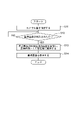
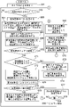
- FIG. 9 is a flowchart showing an example of the operation of the registration unit 151 in the adjustment phase of the individual identification device 100.
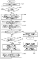
- FIG. 10 is a flowchart showing an example of the operation of the collating unit 152 in the adjustment phase of the individual identification device 100.
- the operation of the registration unit 151 in the adjustment phase of the individual identification device 100 will be described with reference to FIG.
- the control unit 1514 of the registration unit 151 is instructed to start the adjustment phase by, for example, an operator command from the operation input unit 120
- the camera position information is input from the operator
- the shooting condition setting unit 1511 performs the first process processing device 201.
- the position of the camera 211 of the above is adjusted to a position suitable for the collation area of the product manufactured on the production line 200 (step S11). Since the optimum collation area of the product differs depending on the product type, the operator adjusts by inputting the position information of the camera 211 according to the type of the product to be manufactured from the operation input unit 120.
- the camera 211 collates the product side surface portion having a width W separated from the tip of the product 241 by a distance L1 as described with reference to FIGS. 3 and 4. It is assumed that the camera position has been adjusted so that it can be photographed.
- the operator places the reference product on the conveyor 203 and carries it toward the first process processing device 201.
- the reference product is carried into the first process processing device 201, it is detected by a sensor (not shown) installed in the first process processing device 201, and when the tip of the reference product reaches a predetermined position X1, it is temporarily The transportation is stopped and the reference product is put into a stationary state. Further, the first process processing device 201 notifies the individual identification device 100 that the product has been delivered to the first process processing device 201 by communication.
- the registration image acquisition unit 1512 acquires the image of the collation area of the reference product as the reference image 142, and the storage unit 1513. Is stored in the storage unit 140 (step S13).
- the control unit 1514 reads out the reference image 142 from the storage unit 140 and displays it on the screen display unit 130, and notifies the operator that the acquisition of the reference image is completed (step S14).
- the position of the camera 211 of the first process processing device 201 of the production line 200 is adjusted by the operation of the registration unit 151 of the adjustment phase, and the collation area of the reference product photographed under the adjusted camera position is used.
- the reference image 142 which is an image, is stored in the storage unit 140.
- the operation of the collation unit 152 in the adjustment phase will be described.
- the operator instructs, for example, the operation input unit 120 to start the adjustment phase to the control unit 1525 of the collation unit 152.
- the operator first inputs information on the same camera position as the camera position of the adjusted camera 211 from, for example, the operation input unit 120.
- the control unit 1525 of the collation unit 152 is instructed to start the adjustment phase, the process shown in FIG. 10 is started, and the camera of the second process processing device 202 is started by the shooting condition setting unit 1521 according to the input camera position information.
- the position of 212 is adjusted (step S21).
- the position of the camera 212 is adjusted to a position that substantially matches the collation area of the product processed by the second process processing device 202.
- the collation area of the product photographed by the camera 212 of the second process processing device 202 is displaced from the collation area of the product photographed by the camera 211 of the first process processing device 201. May have occurred.
- the operator takes out the reference product carried into the first process processing device 201 from the first process processing device 201, places it on the transfer machine 204, and conveys it toward the second process processing device 202.
- the reference product is carried into the second process processing device 202 by the transfer machine 204, it is detected by a sensor (not shown) installed in the second process processing device 202, and when the tip of the reference product reaches a predetermined position X2. , The transportation is temporarily stopped, and the standard product is put into a stationary state.
- the second process processing device 202 notifies the individual identification device 100 that the reference product has been delivered to the second process processing device 202 by communication.
- the collating area of the product photographed by the camera 212 and the collating area of the product photographed by the camera 211 are used with the reference product. Adjust the position of the camera 212 as follows so that there is no misalignment between the two.
- control unit 1525 initially sets the current change direction to the upstream direction, the previous collation score to 0, and the current camera position to the camera position adjusted in step S21 (step S23).
- the control unit 1525 acquires a collation image, which is an image of the collation area of the reference product, by the collation image acquisition unit 1522 under the current camera position (step S24). That is, the control unit 1525 adjusts the position of the camera 212 to the current camera position by the camera position adjuster 222, and acquires the collation image of the reference product by the collation image acquisition unit 1522.
- the control unit 1525 collates the collation image acquired in the immediately preceding step S24 with the reference image 142 stored in the storage unit 140 by the collation unit 1523, and calculates a collation score indicating the degree of matching between the two. , The calculated collation score is set as the current collation score (step S25).
- control unit 1525 determines whether or not the current collation score is larger than a preset threshold value (step S26).
- the above threshold is predetermined under the condition that the distribution of the average matching score of the same individual and the distribution of the average matching score of different individuals are sufficiently separated.
- the control unit 1525 saves the current camera position as the adjusted collation camera position (step S27), and ends the process of FIG.
- the control unit 1525 determines whether or not the current collation score is larger than the previous collation score (step S28). Next, if the current collation score is larger than the previous collation score, the control unit 1525 saves the current camera position and the current collation score as the previous camera position and the previous collation score (step S29), and proceeds to step S32. If the current collation score is not larger than the previous collation score, the control unit 1525 returns the current camera position to the same camera position as the previous camera position (step S30), and changes the current change direction to the downstream direction (step S31). , Step S32.
- step S32 the control unit 1525 sets the camera position in which the current camera position is changed by a unit amount in the current change direction as the new current camera position. Then, the control unit 1525 returns to step S24 and repeats the same processing as described above. Then, the control unit 1525 finishes the repetition of the above process when the current collation score becomes larger than the threshold value, and saves the current camera position at that time as the adjusted collation camera position (step S27). Then, the control unit 1525 ends the process of FIG.
- the collation unit 152 in the adjustment phase, while changing the camera position when the collation area of the reference product is photographed by the camera 212, the collation image, which is the image of the collation area of the reference product, is captured and the collation image is captured. And the reference image are repeatedly collated, and the camera position of the camera 212 whose collation score between the collated image and the reference image is equal to or higher than a preset threshold value is determined.
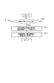
- FIG. 11 is a flowchart showing an example of the operation of the registration unit 151 in the operation phase of the individual identification device 100.
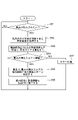
- FIG. 12 is a flowchart showing an example of the operation of the collating unit 152 in the operation phase of the individual identification device 100.
- the operation of the registration unit 151 in the operation phase of the individual identification device 100 will be described with reference to FIG.
- the operation phase when the product is carried into the first process processing device 201, it is detected by a sensor (not shown) installed in the first process processing device 201, and when the tip of the product reaches a predetermined position X1, it is temporarily generated. The transportation is stopped, and the product is put into a stationary state. Further, the first process processing device 201 notifies the individual identification device 100 that the product has been delivered to the first process processing device 201 by communication.
- the control unit 1514 of the registration unit 151 detects the delivery of the product by this communication (YES in step S41)
- the registration image acquisition unit 1512 acquires the image of the collation area of the product as the registration image (step S42).
- the control unit 1514 stores the registered image and the manufacturing information of the product acquired from the first process processing device 201 in the product DB 143 of the storage unit 140 by the storage unit 1513 (step S43). The above operation is repeated every time the product is carried into the first process processing apparatus 201.
- the operation of the collation unit 152 in the operation phase will be described.
- the product is carried into the second process processing device 202 by the transfer machine 204, it is detected by a sensor (not shown) installed in the second process processing device 202, and when the tip of the product reaches a predetermined position X2, it is temporarily The transportation is stopped, and the product is put into a stationary state.
- the second process processing device 202 notifies the individual identification device 100 that the product has been delivered to the second process processing device 202 by communication.
- the collation image acquisition unit 1522 acquires an image of the collation area of the product as a collation image (step S52).
- the control unit 1525 collates the collation image with one or more registered images stored in the product DB 143 by the collation unit 1523, and calculates a collation score (step S53).
- the collation unit 1523 has not succeeded in collating with the collation image of the second process processing device among the registered images registered in the product DB 143 as one or more registered images to be collated with the collation image.
- the registered image G101 is collated with the collation image G201 successfully, so that the registered images G102 to G108 are collated in order. do.
- control unit 1525 determines that the product related to the collation image is the same as the product related to the registered image whose collation score is larger than the threshold value. Determination (step S55). In this case, the control unit 1525 stores the collated image and the manufacturing information acquired from the second process processing device 202 in the product DB 143 in association with the collated registered image by the storage unit 1524 (step S56). .. Then, the process returns to step S51, and the same process as described above is repeated.
- step S57 the control unit 1525 performs error processing (step S57), and then returns to step S51. Then, the same process as described above is repeated.
- the operation phase under the camera position adjusted in the adjustment phase, the registered image of the product carried into the first process processing device 201 and the collation image of the product carried into the second process processing device 202 are displayed. Is acquired and collated, and the individual product is identified.
- the shooting conditions of the collated image can be positively matched with the shooting conditions of the registered image.
- the reason is that, in general, the degree of matching between the registered image of an object taken under a certain camera position and the collation image of the object taken under a certain camera position is such that both camera positions match. This is because it tends to be higher.
- the positions of the cameras 211 and 212 are adjusted only in the upstream direction and the downstream direction (that is, the left-right direction of the paper surface in FIGS. 2 and 4) of the product flow.
- the positions of the cameras 211 and 212 are adjusted in the vertical direction of the paper surface in FIGS. 2 and 4 (that is, the direction toward the product and the direction away from the product), or the vertical direction of the paper surface in FIGS. 2 and 4. It may be adjusted in the direction.
- the positions of the cameras 211 and 212 are adjusted in the left-right direction of the paper surface and the vertical direction of the paper surface in FIGS. 2 and 4, the collation score with the registered image of the reference product is obtained as in the above embodiment.
- the shooting conditions of the collated image can be positively matched with the shooting conditions of the registered image.
- the orientation / posture of the cameras 211 and 212 may be adjusted. Even when the orientation and posture of the cameras 211 and 212 are adjusted in this way, a collation image having a collation score equal to or higher than the threshold value with the registered image of the reference product can be obtained as in the above embodiment.
- the shooting conditions of the collated image can be positively matched with the shooting conditions of the registered image.
- the positions, orientations, postures, etc. of the cameras 211 and 212 are adjusted.
- the lighting conditions such as the irradiation angle of the illuminators 231 and 232 may be adjusted. Even when the lighting conditions of the illuminators 231 and 232 are adjusted in this way, a collation image having a collation score equal to or higher than the threshold value with the registered image of the reference product can be obtained as in the above embodiment.
- the shooting conditions of the collated image can be positively matched with the shooting conditions of the registered image.
- a collation image having a collation score equal to or higher than the threshold value with the registered image of the reference product can be obtained by using the reference product for position adjustment.
- the shooting conditions of the collated image are positively matched with the shooting conditions of the registered image.
- the collated image is obtained so that the collated image having the collation score with the registered image of the product equal to or higher than the threshold value can be obtained by using the product actually produced.
- the shooting conditions may be positively matched with the shooting conditions of the registered image.
- the control unit 1525 of the collation unit 152 adjusts the position of the camera 212 to the same camera position as the camera 211 prior to starting the operation phase (step S61). That is, for example, the operator inputs information on the same camera position as the camera position of the adjusted camera 211 from, for example, the operation input unit 120.
- the control unit 1525 of the collation unit 152 adjusts the position of the camera 212 of the second process processing device 202 by the shooting condition setting unit 1521 according to the input camera position information (step S21). As a result, the position of the camera 212 is adjusted to a position that substantially matches the collation area of the product processed by the second process processing device 202.
- the collation area of the product photographed by the camera 212 of the second process processing device 202 is displaced from the collation area of the product photographed by the camera 211 of the first process processing device 201. May have occurred.
- the product when carried into the second process processing device 202 by the conveyor 204, it is detected by a sensor (not shown) installed in the second process processing device 202, and when the tip of the product reaches a predetermined position X2. , The transportation is temporarily stopped, and the product is put into a stationary state.
- the second process processing device 202 notifies the individual identification device 100 that the product has been delivered to the second process processing device 202 by communication.
- the control unit 1525 of the collation unit 152 detects the delivery of the product (step S62), it pays attention to one of the registered images of the product DB 143 (step S63).
- control unit 1525 initializes the current change direction to the upstream direction, the previous collation score to 0, the current camera position to the camera position adjusted in step S61, and the number of changes to 0 (step S64). Then, the control unit 1525 acquires an image of the collation area of the carried-in product as a collation image under the current camera position by the collation image acquisition unit 1522 (step S65).
- control unit 1525 collates the collation image with the registered image of interest by the collation unit 1523, and sets the calculated collation score as the current collation score (step S66).
- control unit 1525 determines whether or not the current collation score is larger than a preset threshold value (step S67).
- the control unit 1525 saves the current camera position as the adjusted collation camera position (step S68), and the imported product is the same as the product related to the registered image of the current collation score. (Step S69), and the collation image and the manufacturing information are stored in the product DB 143 in association with the registered image of interest by the storage unit 1524 (step S70). Then, the process returns to the process of step S62.
- the control unit 1525 determines whether or not the current collation score is larger than the previous collation score (step S71). Next, if the current collation score is larger than the previous collation score, the control unit 1525 saves the current camera position and the current collation score as the previous camera position and the previous collation score (step S72), and proceeds to step S75. If the current collation score is not larger than the previous collation score, the control unit 1525 returns the current camera position to the same camera position as the previous camera position (step S73), and changes the current change direction to the downstream direction (step S74). , Proceed to step S75.
- the reason why the amount of misalignment is small is that there is a random pattern unique to each product in the collation area of the product, and for products manufactured using the same manufacturing mold and cutting tool, the manufacturing gold is manufactured in the manufacturing process. This is because the same random pattern due to the type and the like is formed. That is, taking the printed wiring board as an example, the side surface of the printed wiring board before being carried into the first process processing device 201 is formed by the manufacturing mold in addition to the random pattern peculiar to the printed wiring board. A random pattern is formed.
- step S75 the control unit 1525 increments the number of changes.
- the control unit 1525 determines whether or not the number of changes exceeds the preset maximum number of times (step S76), and if not, the camera position where the current camera position is changed by a unit amount in the current change direction. Is the new current camera position (step S79). Then, the control unit 1525 returns to step S65 and repeats the same processing as described above. Further, if the number of changes exceeds the maximum number of changes, the control unit 1525 determines that the collated image did not collate with the registered image being watched, and shifts attention to one of the next registered images (step S77). .. Then, the control unit 1525 returns to step S64 via step S78, and repeats the same processing as the above-mentioned processing for the registered image to which attention has been transferred.
- step S78 when all the registered images to be collated in the product DB 143 have been paid attention to (YES in step S78), the control unit 1525 determines that the registered images collating and matching the collated images did not exist in the product DB 143, and an error occurs. Processing is performed (step S80). Then, the control unit 1525 returns to step S62 and repeats the same processing as described above.
- the collation image is obtained so that the collation score with the registered image of the product is equal to or higher than the threshold value for each product actually produced.
- the shooting conditions of the image can be positively matched with the shooting conditions of the registered image.
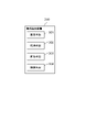
- FIG. 14 is a block diagram of the individual identification device 300 according to the present embodiment.
- the individual identification device 300 includes setting means 301, acquisition means 302, collation means 303, and control means 304.
- the setting means 301 is configured to set shooting conditions when shooting an object collation area with a camera.
- the setting means 301 can be configured in the same manner as, for example, the shooting condition setting unit 1521 of FIG. 7, but is not limited thereto.
- the acquisition means 302 is configured to acquire a collation image, which is an image taken by a camera of the collation area of an object.
- the acquisition means 302 can be configured in the same manner as, for example, the collation image acquisition unit 1522 of FIG. 7, but is not limited thereto.
- the collation means 303 is configured to collate the collation image with the registered image which is an image of the collation area of the pre-registered object. Further, the collation means 303 is configured to identify an individual based on a collation image taken under the shooting conditions determined by the control means 304.
- the collation means 303 can be configured in the same manner as, for example, the collation unit 1523 in FIG. 7, but is not limited thereto.
- the control means 304 repeats a process of acquiring a collated image by the acquiring means 302 and a process of collating the collated image and the registered image by the collating means 303 while changing the shooting conditions set by the setting means 301, and repeats the collating image. It is configured to determine the shooting conditions in which the degree of coincidence between the image and the registered image is equal to or higher than a preset threshold value.
- the control means 304 can be configured in the same manner as, for example, the control unit 1525 of FIG. 7, but is not limited thereto.
- the individual identification device 300 configured in this way operates as follows. That is, the control means 304 takes a collation image which is an image of the collation area of the object by the acquisition means 302 and the collation means 303 while changing the shooting conditions when the collation area of the object is photographed by the camera by the setting means 301.
- the collation image is repeatedly collated with the registered image which is an image of the collation area of the pre-registered object, and the shooting condition in which the degree of matching between the collation image and the registered image is equal to or higher than a preset threshold value is determined.
- the collation means 303 identifies the individual based on the collation image captured under the determined imaging conditions.
- the shooting conditions of the collated image can be positively matched with the shooting conditions of the registered image.
- the reason is that, in general, the degree of matching between a registered image of an object taken under certain shooting conditions and a collation image of the same object taken under certain shooting conditions is such that both shooting conditions match. This is because it tends to be higher.
- the present invention is applied to individual identification of a product on a production line, but the present invention can be widely applied to individual identification of a place other than the production line.
- the shooting condition that maximizes the matching score with the reference image registered in advance in the smartphone is set. Individual identification can be performed based on the collation image taken under the determined shooting conditions.
- the present invention can be used in the field of identifying an individual, for example, in the field of identifying an individual of a product flowing on a production line.
- a setting means for setting shooting conditions when shooting an object collation area with a camera and An acquisition means for acquiring a collation image, which is an image taken by the camera of the collation area of the object, A collation means for collating the collation image with a pre-registered registered image, While changing the shooting conditions set by the setting means, the process of acquiring the collated image by the acquiring means and the process of collating the collated image with the registered image by the collating means are repeated to obtain the collated image.
- a control means for determining a shooting condition in which the degree of matching with the registered image is equal to or higher than a preset threshold value is provided.
- the collation means is an individual identification device that identifies an individual based on the collation image captured under the determined imaging conditions.
- the registered image is an image obtained by photographing a collation area of the same object as the object related to the collation image.
- the registered image is an image obtained by photographing a collation area of an object manufactured on the same production line as the object related to the collation image.
- the control means determines the degree of coincidence between the collated image and the registered image after changing the shooting conditions by a certain value in a certain direction, and sets the collated image and the registered image before changing the shooting conditions.
- the control means uses a product for position adjustment to acquire the collation image by the acquisition means while changing the shooting conditions set by the setting means, and the collation image and the registration by the collation means.
- the process of collating the image is repeated to determine the shooting conditions in which the degree of matching between the collated image and the registered image is equal to or higher than a preset threshold value, and the collation means is different from the product for position adjustment.
- the individual is identified based on the collation image taken under the determined shooting conditions for the product of.
- the individual identification device according to any one of Supplementary note 1 to 4.
Landscapes
- Engineering & Computer Science (AREA)
- Theoretical Computer Science (AREA)
- Computer Vision & Pattern Recognition (AREA)
- Multimedia (AREA)
- General Physics & Mathematics (AREA)
- Physics & Mathematics (AREA)
- Computing Systems (AREA)
- General Health & Medical Sciences (AREA)
- Medical Informatics (AREA)
- Software Systems (AREA)
- Evolutionary Computation (AREA)
- Databases & Information Systems (AREA)
- Artificial Intelligence (AREA)
- Health & Medical Sciences (AREA)
- Signal Processing (AREA)
- Quality & Reliability (AREA)
- Image Analysis (AREA)
- Image Processing (AREA)
Priority Applications (4)
| Application Number | Priority Date | Filing Date | Title |
|---|---|---|---|
| JP2022556354A JPWO2022085185A1 (cg-RX-API-DMAC7.html) | 2020-10-23 | 2020-10-23 | |
| EP20951837.2A EP4024847A4 (en) | 2020-10-23 | 2020-10-23 | Individual identification device |
| US17/639,433 US12183057B2 (en) | 2020-10-23 | 2020-10-23 | Individual identification apparatus |
| PCT/JP2020/039926 WO2022085185A1 (ja) | 2020-10-23 | 2020-10-23 | 個体識別装置 |
Applications Claiming Priority (1)
| Application Number | Priority Date | Filing Date | Title |
|---|---|---|---|
| PCT/JP2020/039926 WO2022085185A1 (ja) | 2020-10-23 | 2020-10-23 | 個体識別装置 |
Publications (1)
| Publication Number | Publication Date |
|---|---|
| WO2022085185A1 true WO2022085185A1 (ja) | 2022-04-28 |
Family
ID=81290332
Family Applications (1)
| Application Number | Title | Priority Date | Filing Date |
|---|---|---|---|
| PCT/JP2020/039926 Ceased WO2022085185A1 (ja) | 2020-10-23 | 2020-10-23 | 個体識別装置 |
Country Status (4)
| Country | Link |
|---|---|
| US (1) | US12183057B2 (cg-RX-API-DMAC7.html) |
| EP (1) | EP4024847A4 (cg-RX-API-DMAC7.html) |
| JP (1) | JPWO2022085185A1 (cg-RX-API-DMAC7.html) |
| WO (1) | WO2022085185A1 (cg-RX-API-DMAC7.html) |
Cited By (2)
| Publication number | Priority date | Publication date | Assignee | Title |
|---|---|---|---|---|
| JP2024063953A (ja) * | 2022-10-27 | 2024-05-14 | 株式会社アーステクニカ | 識別装置、選別装置、及び識別方法 |
| WO2026063078A1 (ja) * | 2024-09-17 | 2026-03-26 | 株式会社日立製作所 | 撮影支援装置、撮影システムおよび撮影支援方法 |
Citations (3)
| Publication number | Priority date | Publication date | Assignee | Title |
|---|---|---|---|---|
| JPS626645B2 (cg-RX-API-DMAC7.html) | 1978-12-22 | 1987-02-12 | Hitachi Ltd | |
| WO1993001559A1 (en) * | 1991-07-12 | 1993-01-21 | Omron Corporation | Apparatus and method for determining or setting adequate illuminating and photographing condition, etc., in picture processing system; and apparatus and method for aiding the determination or setting |
| JP2020096325A (ja) * | 2018-12-14 | 2020-06-18 | キヤノン株式会社 | 情報処理装置、情報処理装置の制御方法及びプログラム |
Family Cites Families (17)
| Publication number | Priority date | Publication date | Assignee | Title |
|---|---|---|---|---|
| JP2008145226A (ja) * | 2006-12-08 | 2008-06-26 | Olympus Corp | 欠陥検査装置及び欠陥検査方法 |
| JP5868005B2 (ja) * | 2011-02-04 | 2016-02-24 | キヤノン株式会社 | 撮像装置、撮像条件設定方法、プログラム |
| JP6206645B2 (ja) | 2013-06-25 | 2017-10-04 | 日本電気株式会社 | 携帯端末、撮影方法及びプログラム |
| US10262427B2 (en) * | 2014-09-01 | 2019-04-16 | Nec Corporation | Determination method, determination system, determination device, and program |
| JP6864267B2 (ja) * | 2015-02-27 | 2021-04-28 | 日本電気株式会社 | 照合システム、照合装置、照合方法及びプログラム |
| JP6765791B2 (ja) * | 2015-08-25 | 2020-10-07 | キヤノン株式会社 | パターンマッチング用の基準画像セットの作成方法、パターンマッチング用の基準画像セットの作成装置、ワークの認識方法、プログラム、及び記録媒体 |
| JP6817547B2 (ja) * | 2015-10-02 | 2021-01-20 | 日本電気株式会社 | 個体識別子抽出装置 |
| US11037326B2 (en) * | 2016-11-30 | 2021-06-15 | Nec Corporation | Individual identifying device |
| WO2019122271A1 (en) * | 2017-12-20 | 2019-06-27 | Alpvision S.A. | Authentication machine learning from multiple digital representations |
| JP6977634B2 (ja) * | 2018-03-13 | 2021-12-08 | オムロン株式会社 | 外観検査装置、外観検査方法及びプログラム |
| JP6708695B2 (ja) * | 2018-04-20 | 2020-06-10 | ファナック株式会社 | 検査装置 |
| US11983864B2 (en) * | 2018-08-23 | 2024-05-14 | Nec Corporation | Object matching device |
| WO2020110576A1 (ja) * | 2018-11-27 | 2020-06-04 | キヤノン株式会社 | 情報処理装置 |
| WO2020110269A1 (ja) * | 2018-11-29 | 2020-06-04 | 日本電気株式会社 | 個体識別装置 |
| US12223656B2 (en) * | 2020-03-27 | 2025-02-11 | Nec Corporation | Individual identification system |
| US12190497B2 (en) * | 2020-03-30 | 2025-01-07 | Nec Corporation | Individual identification system |
| JP7377159B2 (ja) * | 2020-04-30 | 2023-11-09 | 株式会社デンソー | 個体識別システム、個体識別プログラム、及び記録媒体 |
-
2020
- 2020-10-23 JP JP2022556354A patent/JPWO2022085185A1/ja active Pending
- 2020-10-23 WO PCT/JP2020/039926 patent/WO2022085185A1/ja not_active Ceased
- 2020-10-23 US US17/639,433 patent/US12183057B2/en active Active
- 2020-10-23 EP EP20951837.2A patent/EP4024847A4/en not_active Withdrawn
Patent Citations (3)
| Publication number | Priority date | Publication date | Assignee | Title |
|---|---|---|---|---|
| JPS626645B2 (cg-RX-API-DMAC7.html) | 1978-12-22 | 1987-02-12 | Hitachi Ltd | |
| WO1993001559A1 (en) * | 1991-07-12 | 1993-01-21 | Omron Corporation | Apparatus and method for determining or setting adequate illuminating and photographing condition, etc., in picture processing system; and apparatus and method for aiding the determination or setting |
| JP2020096325A (ja) * | 2018-12-14 | 2020-06-18 | キヤノン株式会社 | 情報処理装置、情報処理装置の制御方法及びプログラム |
Cited By (2)
| Publication number | Priority date | Publication date | Assignee | Title |
|---|---|---|---|---|
| JP2024063953A (ja) * | 2022-10-27 | 2024-05-14 | 株式会社アーステクニカ | 識別装置、選別装置、及び識別方法 |
| WO2026063078A1 (ja) * | 2024-09-17 | 2026-03-26 | 株式会社日立製作所 | 撮影支援装置、撮影システムおよび撮影支援方法 |
Also Published As
| Publication number | Publication date |
|---|---|
| US20230351723A1 (en) | 2023-11-02 |
| EP4024847A4 (en) | 2022-09-28 |
| US12183057B2 (en) | 2024-12-31 |
| JPWO2022085185A1 (cg-RX-API-DMAC7.html) | 2022-04-28 |
| EP4024847A1 (en) | 2022-07-06 |
Similar Documents
| Publication | Publication Date | Title |
|---|---|---|
| CN112369007B (zh) | 图像处理设备、图像处理设备的控制方法和存储介质 | |
| CN115278071B (zh) | 图像处理方法、装置、电子设备和可读存储介质 | |
| CN113473025A (zh) | 云台调整方法、云台调整设备、移动平台及介质 | |
| US20120162387A1 (en) | Imaging parameter acquisition apparatus, imaging parameter acquisition method and storage medium | |
| CN107633206A (zh) | 眼球动作捕捉方法、装置及存储介质 | |
| US20100123804A1 (en) | Emotion-based image processing apparatus and image processing method | |
| WO2016088368A1 (ja) | 方向制御装置、方向制御方法および記録媒体 | |
| US12183057B2 (en) | Individual identification apparatus | |
| US11455481B2 (en) | Image processing apparatus, image processing method, and storage medium storing program | |
| CN107277380B (zh) | 一种变焦方法及装置 | |
| CN107016330A (zh) | 通过预记录的图像投影对欺诈进行检测的方法 | |
| TWI622018B (zh) | 影片編輯方法、裝置及系統 | |
| JP4383790B2 (ja) | 携帯情報端末 | |
| WO2018101135A1 (ja) | 撮影調整情報導出装置、撮影装置、撮影調整情報導出方法、制御プログラム、および記録媒体 | |
| JP2009076020A (ja) | 虹彩認識装置 | |
| US20030017758A1 (en) | Apparatus for and method of mounting electronic parts | |
| CN111435418B (zh) | 机器人个性化物体识别方法、装置、存储介质及机器人 | |
| US11800230B2 (en) | Image processing apparatus of reducing whole operation time of arrival inspection, image processing method, and storage medium | |
| JP4172728B2 (ja) | 画像処理方法 | |
| CN113034369B (zh) | 一种基于多摄像头的图像生成方法、装置和计算机设备 | |
| TW202429379A (zh) | 複檢影像處理方法與複檢系統 | |
| US20220164590A1 (en) | Methods and systems for identifying and authenticating provenance of watches | |
| JPH1063842A (ja) | テンプレートマッチング方法 | |
| WO2023021668A1 (ja) | 撮影ガイド装置 | |
| JP6933125B2 (ja) | 情報処理装置,撮影ガイド表示プログラム,撮影ガイド表示方法 |
Legal Events
| Date | Code | Title | Description |
|---|---|---|---|
| ENP | Entry into the national phase |
Ref document number: 2020951837 Country of ref document: EP Effective date: 20220330 |
|
| ENP | Entry into the national phase |
Ref document number: 2022556354 Country of ref document: JP Kind code of ref document: A |
|
| NENP | Non-entry into the national phase |
Ref country code: DE |
|
| WWW | Wipo information: withdrawn in national office |
Ref document number: 2020951837 Country of ref document: EP |