WO2022085103A1 - ばね構造体及びその製造方法 - Google Patents
ばね構造体及びその製造方法 Download PDFInfo
- Publication number
- WO2022085103A1 WO2022085103A1 PCT/JP2020/039518 JP2020039518W WO2022085103A1 WO 2022085103 A1 WO2022085103 A1 WO 2022085103A1 JP 2020039518 W JP2020039518 W JP 2020039518W WO 2022085103 A1 WO2022085103 A1 WO 2022085103A1
- Authority
- WO
- WIPO (PCT)
- Prior art keywords
- spring
- coil springs
- main body
- spring structure
- coil
- Prior art date
- Legal status (The legal status is an assumption and is not a legal conclusion. Google has not performed a legal analysis and makes no representation as to the accuracy of the status listed.)
- Ceased
Links
Images




Classifications
-
- F—MECHANICAL ENGINEERING; LIGHTING; HEATING; WEAPONS; BLASTING
- F16—ENGINEERING ELEMENTS AND UNITS; GENERAL MEASURES FOR PRODUCING AND MAINTAINING EFFECTIVE FUNCTIONING OF MACHINES OR INSTALLATIONS; THERMAL INSULATION IN GENERAL
- F16F—SPRINGS; SHOCK-ABSORBERS; MEANS FOR DAMPING VIBRATION
- F16F3/00—Spring units consisting of several springs, e.g. for obtaining a desired spring characteristic
- F16F3/02—Spring units consisting of several springs, e.g. for obtaining a desired spring characteristic with springs made of steel or of other material having low internal friction
- F16F3/04—Spring units consisting of several springs, e.g. for obtaining a desired spring characteristic with springs made of steel or of other material having low internal friction composed only of wound springs
-
- F—MECHANICAL ENGINEERING; LIGHTING; HEATING; WEAPONS; BLASTING
- F16—ENGINEERING ELEMENTS AND UNITS; GENERAL MEASURES FOR PRODUCING AND MAINTAINING EFFECTIVE FUNCTIONING OF MACHINES OR INSTALLATIONS; THERMAL INSULATION IN GENERAL
- F16F—SPRINGS; SHOCK-ABSORBERS; MEANS FOR DAMPING VIBRATION
- F16F1/00—Springs
- F16F1/02—Springs made of steel or other material having low internal friction; Wound, torsion, leaf, cup, ring or the like springs, the material of the spring not being relevant
- F16F1/04—Wound springs
- F16F1/12—Attachments or mountings
-
- F—MECHANICAL ENGINEERING; LIGHTING; HEATING; WEAPONS; BLASTING
- F16—ENGINEERING ELEMENTS AND UNITS; GENERAL MEASURES FOR PRODUCING AND MAINTAINING EFFECTIVE FUNCTIONING OF MACHINES OR INSTALLATIONS; THERMAL INSULATION IN GENERAL
- F16F—SPRINGS; SHOCK-ABSORBERS; MEANS FOR DAMPING VIBRATION
- F16F13/00—Units comprising springs of the non-fluid type as well as vibration-dampers, shock-absorbers, or fluid springs
- F16F13/005—Units comprising springs of the non-fluid type as well as vibration-dampers, shock-absorbers, or fluid springs comprising both a wound spring and a damper, e.g. a friction damper
- F16F13/007—Units comprising springs of the non-fluid type as well as vibration-dampers, shock-absorbers, or fluid springs comprising both a wound spring and a damper, e.g. a friction damper the damper being a fluid damper
-
- F—MECHANICAL ENGINEERING; LIGHTING; HEATING; WEAPONS; BLASTING
- F16—ENGINEERING ELEMENTS AND UNITS; GENERAL MEASURES FOR PRODUCING AND MAINTAINING EFFECTIVE FUNCTIONING OF MACHINES OR INSTALLATIONS; THERMAL INSULATION IN GENERAL
- F16F—SPRINGS; SHOCK-ABSORBERS; MEANS FOR DAMPING VIBRATION
- F16F2226/00—Manufacturing; Treatments
- F16F2226/04—Assembly or fixing methods; methods to form or fashion parts
- F16F2226/048—Welding
Definitions
- the present invention relates to a spring structure and a method for manufacturing the spring structure.
- the spring structure is arranged so that a plurality of coil springs are vertically arranged and overlapped at regular intervals.
- both ends of the coil spring are called end turns, which are formed in a flat shape and are used as a part for contacting the support member that supports the spring.
- the end-rolled portion has almost no function as an elastic body. On the other hand, it is desired to reduce the weight of the coil spring.
- An object of the present invention is to provide a spring structure or the like that can be reduced in weight.
- the present inventor has found that by removing the end turn portion from the conventional coil spring, it is possible to provide a coil spring that is lighter than the conventional one while leaving a portion that functions as an elastic body.
- the present invention was completed.
- the present inventor also examined a structure for stably supporting the coil spring excluding the end turn portion, and specified a preferable form that the present invention can take.
- a spring body with a plurality of coil springs arranged coaxially and all windings separated from adjacent windings, and a shaft of the spring body.
- a spring structure is provided that is disposed at both ends in the direction and has a support portion that supports the axial end portion of the spring body portion.
- a method for manufacturing a spring structure is provided, which comprises a sandwiching step of sandwiching the spring main body portion between the pair of the support portions.
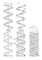
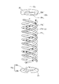
- FIG. 2 It is a front view of the rear cushion on which the spring structure according to Example 1 is mounted. It is a perspective view of the spring structure shown in FIG. FIG. 2 is a sectional view taken along line 3-3 of FIG. It is a perspective view of the support part shown in FIG. It is a flow figure explaining the manufacturing method of a spring structure. It is a figure explaining the coil spring manufacturing process. It is a figure explaining the process of manufacturing a spring body part. It is a figure explaining the pinching process. It is a figure explaining the 1st modification example of the coil spring shown in FIG. It is a figure explaining the 2nd modification example of the coil spring shown in FIG. It is a perspective view of the support part used for the spring structure by Example 2. FIG. It is a perspective view of the support part used for the spring structure by Example 3. FIG. It is a figure explaining the connection process of the coil spring used for the spring structure by Example 4. FIG.
- left and right refer to left and right based on the occupant of the vehicle
- front and rear refer to front and rear based on the traveling direction of the vehicle.
- the form shown in the attached figure is an example of the present invention, and the present invention is not limited to this form.
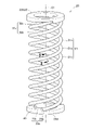
- the spring structure 20 constitutes, for example, a part of the rear cushion 10 used for the rear part of the two-wheeled vehicle.
- the rear cushion 10 is a spring structure that urges the vehicle body side member 11 connected to the vehicle body, the wheel side member 12 connected to the wheels, and the vehicle body side member 11 and the wheel side member 12 in a direction away from each other. It has 20 and.
- the spring structure 20 is arranged at both ends of the spring main body 21 composed of three coil springs 21a to 21c in the axial CL direction (both ends in the vertical direction of the paper surface in FIG. 2) of the spring main body 21, respectively. It has support portions 22 and 23 that support the end portion of the portion 21 in the axis CL direction.
- a compression coil spring is used for the coil springs 21a to 21c constituting the spring structure 20.
- the coil springs 21a to 21c each have the same shape and are arranged coaxially at the same height. Further, in the coil springs 21a to 21c, all the windings are separated from the windings adjacent to the windings. That is, the coil springs 21a to 21c are compression coil springs having no end turn portion.
- the pitch of the coil springs 21a to 21c does not have to be constant throughout the axial direction, and may be changed as appropriate.
- the coil spring 21a exhibits a solid circular cross-sectional shape. The same applies to the other two coil springs 21b and 21c (see FIG. 2).
- the two support portions 22 and 23 have the same configuration, respectively.
- the support portion 22 that receives the upper end in the axial direction of the spring main body portion 21 is fixed to the vehicle body side member 11 (see FIG. 1).
- the support portion 22 fixed to the vehicle body side member 11 is appropriately referred to as an "upper support portion 22".
- the support portion 23 that receives the lower end of the spring main body portion 21 is fixed to the wheel side member 12 (see FIG. 1).
- the support portion 23 fixed to the wheel side member 12 is appropriately referred to as a "lower support portion 23".
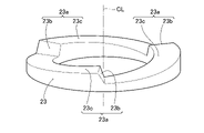
- the lower support portion 23 has a ring shape. Of the lower support portions 23, the contact surface 23a with which the spring main body portion 21 is in contact is raised in a wall shape so as to be inclined with respect to the lower surface 23d of the lower support portion 23, and the three coil springs 21a to 21c. It has a regulation unit 23b that regulates the rotational movement around the axis CL of the above. Further, the lower support portion 23 is arranged so that the height of the lower support portion 23 in the axis CL direction decreases from the upper end of each regulation portion 23b toward the lower end of the regulation portion 23b adjacent to the regulation portion 23b in a clockwise direction. Includes an inclined portion 23c that connects these two regulating portions 23b.
- Three regulating portions 23b are formed at equal intervals in the circumferential direction of the lower support portion 23.
- the regulation unit 23b is tilted with respect to the axis CL.
- the inclined portion 23c serves to return the coil springs 21a to 21c separated from the regulating portion 23b so as to be in contact with the regulating portion 23b even when the coil springs 21a to 21c are separated from the regulating portion 23b.
- the upper support portion 22 has the same configuration as the lower support portion 23. That is, the contact surface 22a is raised like a wall so as to be inclined with respect to the upper surface 22d of the upper support portion 22, and is regulated to regulate the rotational movement of the three coil springs 21a to 21c around the axis CL. It has a portion 22b.
- the upper support portion 22 is further so that the height of the upper support portion 22 in the axis CL direction decreases from the upper end of each regulation portion 22b toward the lower end of the regulation portion 22b adjacent to the regulation portion 22b in a clockwise direction. Includes an inclined portion 22c that connects these two regulating portions 22b.
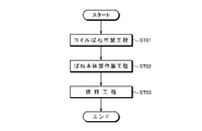
- the method for manufacturing the spring structure 20 includes a coil spring manufacturing step (ST01), a spring body portion manufacturing step (ST02), and a sandwiching step (ST03) in this order. See FIGS. 5 and 6.
- coil spring manufacturing step ST01
- spring body portion manufacturing step ST02
- sandwiching step ST03
- FIGS. 5 and 6 When manufacturing the spring structure 20, first, for example, three coil springs 21a to 21c in which all the windings are separated from the windings adjacent to the windings are manufactured (coil spring manufacturing step, ST01). ).
- the number of coil springs produced may be plural.
- the method for manufacturing the coil springs 21a to 21c plastic working, molding with a mold, laminated molding, or the like can be selected.
- a well-known spring manufacturing method can be selected in addition to these.
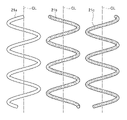
- the three manufactured coil springs 21a to 21c are arranged coaxially so as to have the same height, and the spring main body portion 21 is manufactured (spring main body portion manufacturing step, ST02). More specifically, the second coil spring 21b is coaxially arranged with respect to one coil spring 21a while rotating. Since the two coil springs 21a and 21b are formed in the same shape, they can be arranged at the same height by arranging them out of phase. Similarly, the third coil spring 21c is arranged while rotating with respect to the two coil springs 21a and 21b.
- the spring main body portion 21 is sandwiched between the pair of support portions 22 and 23 (pinching step, ST03).
- the regulation portions 22b are formed on the support portions 22 and 23 at the ends of the coil springs 21a to 21c so as to regulate the rotational movement of the coil springs 21a to 21c around the axis CL. , 23b.
- the spring structure 20 (see FIG. 2) is completed.
- the spring structure 20 includes a plurality of (for example, three) coil springs 21a to 21c that are coaxially arranged at the same height and all windings are separated from the winding adjacent to the winding. It has a spring main body portion 21 and support portions 22 and 23 which are arranged at both ends of the spring main body portion 21 in the axial CL direction and support the axial CL direction end portions of the spring main body portion 21.
- the spring structure 20 includes a coil spring manufacturing step (see FIG. 6) in which a plurality of coil springs 21a to 21c in which all the windings are separated from the windings adjacent to the windings are manufactured, and a plurality of manufactured coil springs.
- a spring main body manufacturing step (see FIG. 7) for manufacturing a spring main body 21 including coil springs 21a to 21c by arranging 21a to 21c coaxially at the same height, and the manufactured spring main body.
- the support portions 22 and 23 that support the ends of the spring main body portion 21 in the axial direction CL direction at both ends in the axial direction of the spring 21, the spring main body portion 21 is sandwiched between the pair of support portions 22 and 23. It has a step (see FIG. 8).
- a plurality of coil springs 21a to 21c are brought into contact with the support portions 22 and 23.
- the support portions 22 and 23 are in contact with the ends of the coil springs 21a to 21c, and at least one support portion (two support portions 22 and 23 in the spring structure 20) constitutes at least the spring main body portion 21. It has regulating portions 22b and 23b that regulate the rotational movement of one coil spring 21a to 21c about the axis CL.
- the ends of the coil springs 21a to 21c are formed on the support portions 22 and 23 so as to regulate the rotational movement of the coil springs 21a to 21c around the axis CL. It is brought into contact with the regulating portions 22b and 23b.
- the coil springs 21a to 21c can be easily arranged at an accurate position, and the support portions 22 and 23 can be surely brought into contact with each other.
- the support portions 22 and 23 have the regulation portions 22b and 23b, but it is also possible that only one of the support portions 22 and 23 has the regulation portions 22b and 23b. .. Further, in the present invention, the support portions 22 and 23 are formed on the regulating portions 22b and 23b, in other words, the spring structure 20 in contact with the respective ends of the plurality of coil springs 21a to 21c provided in the spring structure 20. It is preferable to provide the same number of regulating portions 22b and 23b as the number of coil springs 21a to 21c provided, but the number of regulating portions 22b and 23b supported by a smaller number than the number of coil springs 21a to 21c provided in the spring structure 20. It may be provided in the portions 22 and 23.
- the number of coil springs 21a to 21c constituting the spring main body 21 is three. Since the number of coil springs 21a to 21c is three, it becomes easy to stabilize the arrangement of the coil springs 21a to 21c sandwiched by the pair of support portions 22 and 23.
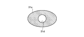
- the coil spring 31a may be a compression coil spring having an elliptical cross-sectional shape with a round hole 31d in the center.
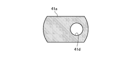
- the coil spring 41a may be a compression coil spring having an oval cross-sectional shape having a round hole 41d at a position offset with respect to the center and processed so that the upper surface and the lower surface of each winding are flat. ..
- Example 2 Next, Example 2 will be described with reference to the drawings.
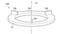
- the spring structure 20A according to the second embodiment has a different shape of the support portion 33 from the spring structure 20 according to the first embodiment (see FIG. 2).
- Other basic configurations are common to the spring structure 20 according to the first embodiment.
- reference numerals are used and detailed description thereof will be omitted.
- the support portion 33 includes a wall-shaped restricting portion 33b that rises perpendicularly to the contact surface 33a.
- Three regulating portions 33b are arranged at equal intervals in the circumferential direction of the supporting portion 33.
- the spring structure 20A described above also has the predetermined effect of the present invention.
- Example 3 Next, Example 3 will be described with reference to the drawings.
- the spring structure 20B according to the third embodiment has a different shape of the support portion 43 from the spring structure 20 according to the first embodiment (see FIG. 2).
- Other basic configurations are common to the spring structure 20 according to the first embodiment.
- reference numerals are used and detailed description thereof will be omitted.
- the support portion 43 includes a pin-shaped regulating portion 43b that rises perpendicularly to the contact surface 43a. Three regulating portions 43b are arranged at equal intervals in the circumferential direction of the supporting portion 43.
- the spring structure 20B described above also has the predetermined effect of the present invention.
- Example 4 Next, Example 4 will be described with reference to the drawings.
- the spring structure 20C according to the fourth embodiment is different from the spring structure 20 according to the first embodiment (see FIG. 2) in the spring body portion 51.
- Other basic configurations are common to the spring structure 20 according to the first embodiment.
- reference numerals are used and detailed description thereof will be omitted.
- coil springs 21a to 21c are connected to each other.
- the spring main body 51 which is connected to each other, connects the three (plural) coil springs 21a to 21c coaxially arranged to each other between the spring main body manufacturing step and the sandwiching step (through the connecting step). ) By doing so.
- the connecting step is performed, for example, by welding the coil springs 21a to 21c to each other by welding.
- the connecting step can also be performed by laminating molding or by using a member that connects the coil springs 21a to 21c to each other.
- the spring structure 20C described above also has the predetermined effect of the present invention.
- the spring main body 51 a plurality of coil springs 21a to 21c are connected to each other.
- the spring main body 51 connects three (plural) coil springs 21a to 21c coaxially arranged between the spring main body manufacturing step and the holding step (connecting step).
- the coil springs 21a to 21c are brought into contact with the support portions 22 and 23 (see FIG. 2). It will be easier.
- the connecting step in the present invention is not limited to the form of connecting all the coil springs constituting the spring structure.
- a part of the coil springs constituting the spring structure for example, in the case of a spring structure having three coil springs 21a to 21c, two coils selected from the three coil springs 21a to 21c. It is also possible to connect only the spring).
- the present invention is not limited to this embodiment.
- the heights of the plurality of coil springs provided in the spring structure may be different from each other.
- the heights of the plurality of coil springs provided in the spring structure are different from each other, for example, in the state after the support portions are arranged at both ends in the axial direction, the upper surface of the upper support portion and the lower surface of the lower support portion are horizontal. It is sufficient to take measures such as changing the shape of the support portion so as to be.
- the spring structure according to the present invention is mounted on the rear cushion of a two-wheeled vehicle
- it can also be applied to a front fork.
- vehicles such as saddle-riding vehicles and passenger cars other than motorcycles, and damper devices such as construction machinery.
- damper devices such as construction machinery. The thing on which the spring structure is mounted is not limited to these.
- each embodiment can be combined as appropriate.
- the coil springs constituting the spring main body of the spring structure shown in the first embodiment can be connected to each other.
- support portions having different shapes as appropriate so that the lower support portion is the lower support portion shown in the first embodiment and the upper support portion is the upper support portion shown in the second embodiment.
- the present invention is not limited to the examples as long as the actions and effects of the present invention are exhibited.
- the spring structure of the present invention is suitable for the rear cushion of a saddle-riding vehicle.
Landscapes
- Engineering & Computer Science (AREA)
- General Engineering & Computer Science (AREA)
- Mechanical Engineering (AREA)
- Springs (AREA)
Abstract
ばね構造体(20)は、全ての巻が当該巻に隣接する巻に対して離間している複数のコイルばね(21a~21c)が、同軸上に配置されてなるばね本体部(21)と、このばね本体部(21)の軸方向両端にそれぞれ配置され、ばね本体部(21)の軸方向端部を支持する支持部(22、23)と、を有する。また、少なくとも1つの支持部(22、23)は、それぞれのコイルばね(21a~21c)の端部に当接し、少なくとも1つのコイルばね(21a~21c)の軸を中心とする回転運動を規制する規制部(22b、23b)を有していてもよい。また、複数のコイルばね(21a~21c)が、互いに連結されていてもよい。
Description
本発明は、ばね構造体及びその製造方法に関する。
多くの車両に搭載されているダンパ装置には、車体に支持されている車体側部材及び車輪を支持している車輪側部材のそれぞれに対して、これらを互いに離間する向きの力を付与するばね構造体が搭載されている。ばね構造体に関する従来技術として特許文献1に開示される技術がある。
特許文献1に示されるような、ばね構造体は、複数のコイルばねが上下に一定間隔で並んで重なるように配置されてなる。
一般的に、コイルばねの両端は座巻と呼ばれ、平面状に形成され、ばねを支える支持部材に当接するための部分として用いられる。座巻部分にてついては、弾性体としての機能をほぼ有していない。一方で、コイルばねを軽量化することが望まれている。
本発明は、軽量化することが可能なばね構造体等の提供を課題とする。
本発明者は、鋭意検討の結果、従来のコイルばねから座巻部分を除くことにより、弾性体として機能する部分を残しつつ、従来よりも軽量化したコイルばねを提供可能になることを知見して、本発明を完成させた。本発明者は、さらに、座巻部分を除いたコイルばねを安定して支持するための構造についても検討し、本発明が採り得る好ましい形態についても特定した。
以下、本開示について説明する。
本開示の1つの態様によれば、同軸上に配置され、すべての巻が当該巻に隣接する巻に対して離間している複数のコイルばねを備えるばね本体部と、前記ばね本体部の軸方向両端にそれぞれ配置され、前記ばね本体部の軸方向端部を支持する支持部と、を有するばね構造体が提供される。
本開示の他の態様によれば、全ての巻が当該巻に隣接する巻に対して離間しているコイルばねを複数作製する、コイルばね作製工程と、作製した複数の前記コイルばねを同軸上に配置することにより複数の前記コイルばねを備えるばね本体部を作製する、ばね本体部作製工程と、作製した前記ばね本体部の軸方向両端に、前記ばね本体部の軸方向端部を支持する支持部をそれぞれ配置することにより、前記ばね本体部を一対の前記支持部で挟持する、挟持工程と、を有する、ばね構造体の製造方法が提供される。
本発明によれば、軽量化することが可能なばね構造体等を提供することができる。
本発明の実施の形態を添付図に基づいて以下に説明する。なお、説明中、左右とは車両の乗員を基準として左右、前後とは車両の進行方向を基準として前後を指す。添付図に示した形態は本発明の一例であり、本発明は当該形態に限定されない。
<実施例1>
図1を参照する。ばね構造体20は、例えば、二輪車の後部に用いられるリヤクッション10の一部を構成する。リヤクッション10は、車体に連結される車体側部材11と、車輪に連結される車輪側部材12と、これらの車体側部材11及び車輪側部材12を互いに離間する方向に付勢するばね構造体20と、を有している。
図1を参照する。ばね構造体20は、例えば、二輪車の後部に用いられるリヤクッション10の一部を構成する。リヤクッション10は、車体に連結される車体側部材11と、車輪に連結される車輪側部材12と、これらの車体側部材11及び車輪側部材12を互いに離間する方向に付勢するばね構造体20と、を有している。
二輪車の走行中に、路面の凹凸に乗り上げた場合等に、車輪側部材12と車体側部材11とは、ばね構造体20の力に抗して互いに近づく。このとき、車輪側部材12又は車体側部材11の内部に配置されているピストン等によって減衰力を発生させ、乗員へと伝達される振動エネルギを抑制する。
図2を併せて参照する。ばね構造体20は、3本のコイルばね21a~21cによって構成されるばね本体部21と、このばね本体部21の軸線CL方向の両端(図2の紙面上下方向両端)にそれぞれ配置さればね本体部21の軸線CL方向の端部を支持する支持部22、23と、を有する。
ばね構造体20を構成するコイルばね21a~21cには、圧縮コイルばねが用いられる。コイルばね21a~21cは、それぞれ同じ形状を呈し、同軸上に同じ高さとなるよう配置されている。また、コイルばね21a~21cは、全ての巻が当該巻に隣接する巻に対して離間している。つまり、コイルばね21a~21cは、座巻部分を有しない圧縮コイルばねである。なお、コイルばね21a~21cのピッチは、軸線方向の全体を通して一定である必要はなく、適宜変更されていても良い。
図3を参照する。コイルばね21aは、中実の円断面形状を呈する。他の2つのコイルばね21b、21c(図2参照)も同様である。
図2を参照する。2つの支持部22、23は、それぞれ同じ構成とされている。ばね本体部21の軸方向上端を受けている支持部22は、車体側部材11(図1参照)に固定されている。車体側部材11に固定されている支持部22を、適宜、「上支持部22」という。ばね本体部21の下端を受けている支持部23は、車輪側部材12(図1参照)に固定されている。車輪側部材12に固定されている支持部23を、適宜、「下支持部23」という。
図4を併せて参照する。下支持部23は、リング状を呈している。下支持部23のうち、ばね本体部21が当接している当接面23aは、下支持部23の下面23dに対して傾斜するように壁状に立ち上げられ3本のコイルばね21a~21cの軸線CLを中心とする回転運動をそれぞれ規制する規制部23bを有している。下支持部23は、さらに、それぞれの規制部23bの上端から当該規制部23bと時計回りに隣接する規制部23bの下端へと向かうにつれて軸線CL方向における下支持部23の高さが低くなるように、これら2つの規制部23bを連結する傾斜部23cと、を含む。
規制部23bは、下支持部23の周方向に等間隔に3つ形成されている。規制部23bは、軸線CLに対して傾いている。
傾斜部23cは、コイルばね21a~21cが規制部23bから離間した場合であっても、規制部23bから離間したコイルばね21a~21cを規制部23bに接触させるように戻す役割を果たす。
上支持部22も下支持部23と同じ構成である。つまり、当接面22aは、上支持部22の上面22dに対して傾斜するように壁状に立ち上げられ3本のコイルばね21a~21cの軸線CLを中心とする回転運動をそれぞれ規制する規制部22bを有している。上支持部22は、さらに、それぞれの規制部22bの上端から当該規制部22bと時計回りに隣接する規制部22bの下端へと向かうにつれて軸線CL方向における上支持部22の高さが低くなるように、これら2つの規制部22bを連結する傾斜部22cと、を含む。
以上に説明したばね構造体20の製造方法を説明する。
図5を参照する。ばね構造体20の製造方法は、コイルばね作製工程(ST01)と、ばね本体部作製工程(ST02)と、挟持工程(ST03)とを、この順に有している。
図5及び図6を参照する。ばね構造体20を製造する際には、まず、全ての巻が当該巻に隣接する巻に対して離間している、例えば3本のコイルばね21a~21cを作製する(コイルばね作製工程、ST01)。作製されるコイルばねの数は、複数であればよい。
図5及び図6を参照する。ばね構造体20を製造する際には、まず、全ての巻が当該巻に隣接する巻に対して離間している、例えば3本のコイルばね21a~21cを作製する(コイルばね作製工程、ST01)。作製されるコイルばねの数は、複数であればよい。
コイルばね21a~21cの作製方法は、塑性加工、金型による成形、積層造形法等、を選択することができる。コイルばね21a~21cは、これらの他にも周知のばね作製方法を選択することができる。
図5及び図7を参照する。作製した3本のコイルばね21a~21cを同軸上に同じ高さになるように配置し、ばね本体部21を作製する(ばね本体部作製工程、ST02)。より詳細には、1つのコイルばね21aに対して、2本目のコイルばね21bを回転させながら同軸上に配置する。2つのコイルばね21a、21bは、同じ形状に形成されているため、位相をずらして配置することにより、同じ高さに配置することができる。同様に、3本目のコイルばね21cを2本のコイルばね21a、21bに対して回転させながら配置する。
図5及び図8を参照する。ばね本体部21の軸線CL方向の両端に、支持部22、23をそれぞれ配置することにより、ばね本体部21を一対の支持部22、23で挟持する(挟持工程、ST03)。挟持工程において、それぞれのコイルばね21a~21cの、軸線CLを中心とする回転運動を規制するように、それぞれのコイルばね21a~21cの端部を支持部22、23に形成された規制部22b、23bに当接させる。これにより、ばね構造体20(図2参照)は、完成する。
以上に説明したばね構造体20の効果を以下に説明する。
図2を参照する。ばね構造体20は、同軸上に同じ高さになるように配置され、全ての巻が当該巻に隣接する巻に対して離間している複数(例えば3本)のコイルばね21a~21cを備えるばね本体部21と、ばね本体部21の軸線CL方向の両端にそれぞれ配置され、ばね本体部21の軸線CL方向端部を支持する支持部22、23と、を有する。
ばね構造体20は、全ての巻が当該巻に隣接する巻に対して離間しているコイルばね21a~21cを複数作製する、コイルばね作製工程(図6参照)と、作製した複数のコイルばね21a~21cを同軸上に同じ高さになるように配置することによりコイルばね21a~21cを備えるばね本体部21を作製する、ばね本体部作製工程(図7参照)と、作製したばね本体部21の軸方向両端に、ばね本体部21の軸線CL方向の端部を支持する支持部22、23をそれぞれ配置することにより、ばね本体部21を一対の支持部22、23で挟持する、挟持工程(図8参照)と、を有する。
複数のコイルばね21a~21cを支持部22、23に当接させる。支持部22、23に当接するコイルばね21a~21cを複数とすることにより、座巻を有しないコイルばね21a~21cであっても支持部22、23に確実に当接させることができる。座巻を有しない分、コイルばね21a~21cを軽量化することができるので、軽量化されたばね構造体20を提供することができる。
また、支持部22、23は、コイルばね21a~21cの端部に当接し、少なくとも1つの支持部(ばね構造体20では2つの支持部22、23)は、ばね本体部21を構成する少なくとも1つのコイルばね21a~21cの軸線CLを中心とする回転運動を規制する規制部22b、23bを有する。一例として、挟持工程において、それぞれのコイルばね21a~21cの、軸線CLを中心とする回転運動を規制するよう、それぞれのコイルばね21a~21cの端部を、支持部22、23に形成された規制部22b、23bに当接させる。これにより、コイルばね21a~21cを正確な位置に配置しやすくなり、支持部22、23により確実に当接させることができる。
なお、全ての支持部22、23が規制部22b、23bを有していることが好ましいが、何れか一方の支持部22、23のみが規制部22b、23bを有していることとしても良い。また、本発明において、支持部22、23は、ばね構造体20に備えられる複数のコイルばね21a~21cのそれぞれの端部と接触する規制部22b、23b、換言すれば、ばね構造体20に備えられるコイルばね21a~21cの数と同数の規制部22b、23bを備えることが好ましいが、ばね構造体20に備えられるコイルばね21a~21cの数よりも少ない数の規制部22b、23bが支持部22、23に備えられていても良い。
ばね本体部21を構成する、コイルばね21a~21cの本数は3本である。コイルばね21a~21cの本数が3本であることにより、一対の支持部22、23によって挟持されるコイルばね21a~21cの配置を安定させやすくなる。
以上に説明したばね構造体20の変形例について、以下説明する。変形例に示すコイルばねを適用した場合にも、所定の効果を奏する。
図9を参照する。コイルばね31aは、中心に丸穴31dが空いている楕円断面形状の圧縮コイルばねであっても良い。
図10を参照する。コイルばね41aは、中心に対してオフセットされた位置に丸穴41dを有し、それぞれの巻の上面及び下面が平面になるように加工された長円断面形状の圧縮コイルばねであっても良い。
<実施例2>
次に、実施例2を図面に基づいて説明する。
次に、実施例2を図面に基づいて説明する。
図11を参照する。実施例2によるばね構造体20Aは、実施例1によるばね構造体20(図2参照)とは、支持部33の形状が異なる。その他の基本的な構成は、実施例1によるばね構造体20と共通する。ばね構造体20と共通する構成については、符号を流用すると共に、詳細な説明を省略する。
支持部33は、当接面33aに対して垂直に立ち上がっている壁状の規制部33bを備えている。規制部33bは、支持部33の周方向に等間隔に3つ配置されている。
以上に説明したばね構造体20Aも、本発明所定の効果を奏する。
<実施例3>
次に、実施例3を図面に基づいて説明する。
次に、実施例3を図面に基づいて説明する。
図12を参照する。実施例3によるばね構造体20Bは、実施例1によるばね構造体20(図2参照)とは、支持部43の形状が異なる。その他の基本的な構成は、実施例1によるばね構造体20と共通する。ばね構造体20と共通する構成については、符号を流用すると共に、詳細な説明を省略する。
支持部43は、当接面43aに対し垂直に立ち上がっているピン状の規制部43bを備えている。規制部43bは、支持部43の周方向に等間隔に3つ配置されている。
以上に説明したばね構造体20Bも、本発明所定の効果を奏する。
<実施例4>
次に、実施例4を図面に基づいて説明する。
次に、実施例4を図面に基づいて説明する。
図13を参照する。実施例4によるばね構造体20Cは、実施例1によるばね構造体20(図2参照)とは、ばね本体部51が異なる。その他の基本的な構成は、実施例1によるばね構造体20と共通する。ばね構造体20と共通する構成については、符号を流用すると共に、詳細な説明を省略する。
ばね本体部51は、コイルばね21a~21cが、互いに連結されている。
互いが連結されているばね本体部51は、ばね本体部作製工程と挟持工程との間に、同軸上に配置した3本(複数)のコイルばね21a~21cを互いに連結する(連結工程を経る)ことにより、得ることができる。
連結工程は、例えば、溶接によりコイルばね21a~21cを互いに溶接することにより行う。なお、連結工程は、溶接の他にも、積層造形やコイルばね21a~21cを互いに連結する部材を用いることによっても行うことができる。
以上に説明したばね構造体20Cも、本発明所定の効果を奏する。
さらに、ばね本体部51は、複数のコイルばね21a~21cが、互いに連結されている。一例として、ばね本体部51は、ばね本体部作製工程と挟持工程との間に、同軸上に配置した3本(複数)のコイルばね21a~21cを互いに連結する(連結工程)。コイルばね21a~21cを互いに連結することにより、ばね構造体20の形状を長期間に亘って維持しやすくなるので、コイルばね21a~21cを支持部22、23(図2参照)に当接させやすくなる。
なお、本発明における連結工程は、ばね構造体を構成するすべてのコイルばねを連結する形態に限定されない。本発明における連結工程は、ばね構造体を構成する一部のコイルばね(例えば、3つのコイルばね21a~21cを有するばね構造体であれば、3つのコイルばね21a~21cから選択した2つのコイルばね)のみを連結する形態にすることも可能である。
また、上記説明では、同じ高さのコイルばね21a~21cを用いる形態を例示したが、本発明は、当該形態に限定されない。本発明は、ばね構造体に備えられる複数のコイルばねの高さが、互いに異なっていても良い。ばね構造体に備えられる複数のコイルばねの高さが互いに異なる場合には、例えば、軸線方向両端に支持部をそれぞれ配置した後の状態では、上支持部の上面及び下支持部の下面が水平になるように、支持部の形状を変更する等の対策を採れば良い。
また、本発明によるばね構造体は、二輪車のリヤクッションに搭載される例を説明したが、フロントフォークに適用することも可能である。さらには、二輪車以外の鞍乗り型車両や乗用車等の車両、建機等のダンパ装置にも適用可能である。ばね構造体が搭載される物は、これらに限られるものではない。
また、各実施例は、適宜組み合わせることもできる。例えば、実施例1に示したばね構造体のばね本体部を構成する各コイルばねを互いに連結することもできる。換言すれば、実施例1に示したばね構造体を製造する際に、連結工程を経ることも可能である。また、下支持部を実施例1に示した下支持部とし、上支持部を実施例2に示した上支持部とするように、適宜異なる形状の支持部を組み合わせることも可能である。
本発明の作用及び効果を奏する限りにおいて、本発明は、実施例に限定されるものではない。
本発明のばね構造体は、鞍乗り型車両のリヤクッションに好適である。
20、20A、20B、20C…ばね構造体
21、51…ばね本体部
21a、21b、21c、31a、41a…コイルばね
22…上支持部(支持部)、22b…規制部
23…下支持部(支持部)、23b…規制部
33、43…支持部
33b、43b…規制部
21、51…ばね本体部
21a、21b、21c、31a、41a…コイルばね
22…上支持部(支持部)、22b…規制部
23…下支持部(支持部)、23b…規制部
33、43…支持部
33b、43b…規制部
Claims (8)
- 同軸上に配置され、全ての巻が当該巻に隣接する巻に対して離間している複数のコイルばねを備えるばね本体部と、
前記ばね本体部の軸方向両端にそれぞれ配置され、前記ばね本体部の軸方向端部を支持する支持部と、を有するばね構造体。 - 前記支持部は、前記ばね本体部を構成するすべてのコイルばねの端部に当接し、少なくとも1つの前記支持部は、前記ばね本体部を構成する少なくとも1つの前記コイルばねの軸を中心とする回転運動を規制する規制部を有する、請求項1に記載のばね構造体。
- 前記ばね本体部を構成する、少なくとも2つの前記コイルばねが、互いに連結されている、請求項1又は請求項2のいずれかに記載のばね構造体。
- 前記ばね本体部を構成する、前記コイルばねの本数は3本である、請求項1~請求項3の何れか1項に記載のばね構造体。
- 全ての巻が当該巻に隣接する巻に対して離間しているコイルばねを複数作製する、コイルばね作製工程と、
作製した複数の前記コイルばねを同軸上に配置することにより複数の前記コイルばねを備えるばね本体部を作製する、ばね本体部作製工程と、
作製した前記ばね本体部の軸方向両端に、前記ばね本体部の軸方向端部を支持する支持部をそれぞれ配置することにより、前記ばね本体部を一対の前記支持部で挟持する、挟持工程と、を有する、ばね構造体の製造方法。 - 少なくとも1つの前記支持部は、前記ばね本体部を構成する少なくとも1つの前記コイルばねの軸を中心とする回転運動を規制する規制部を有し、
前記挟持工程において、前記複数のコイルばねを構成する少なくとも1つの前記コイルばねの端部を前記規制部に当接させる、請求項5に記載のばね構造体の製造方法。 - さらに、前記ばね本体部作製工程と前記挟持工程との間に、
同軸上に配置した前記ばね本体部を構成する少なくとも2つのコイルばねを互いに連結する連結工程を有する、請求項5又は請求項6のいずれかに記載のばね構造体の製造方法。 - 前記ばね本体部作製工程において同軸上に同じ高さになるよう配置される前記コイルばねの本数は、3本である、請求項5~請求項7の何れか1項に記載のばね構造体の製造方法。
Priority Applications (2)
| Application Number | Priority Date | Filing Date | Title |
|---|---|---|---|
| JP2020558639A JPWO2022085103A1 (ja) | 2020-10-21 | 2020-10-21 | |
| PCT/JP2020/039518 WO2022085103A1 (ja) | 2020-10-21 | 2020-10-21 | ばね構造体及びその製造方法 |
Applications Claiming Priority (1)
| Application Number | Priority Date | Filing Date | Title |
|---|---|---|---|
| PCT/JP2020/039518 WO2022085103A1 (ja) | 2020-10-21 | 2020-10-21 | ばね構造体及びその製造方法 |
Publications (1)
| Publication Number | Publication Date |
|---|---|
| WO2022085103A1 true WO2022085103A1 (ja) | 2022-04-28 |
Family
ID=81290202
Family Applications (1)
| Application Number | Title | Priority Date | Filing Date |
|---|---|---|---|
| PCT/JP2020/039518 Ceased WO2022085103A1 (ja) | 2020-10-21 | 2020-10-21 | ばね構造体及びその製造方法 |
Country Status (2)
| Country | Link |
|---|---|
| JP (1) | JPWO2022085103A1 (ja) |
| WO (1) | WO2022085103A1 (ja) |
Citations (6)
| Publication number | Priority date | Publication date | Assignee | Title |
|---|---|---|---|---|
| JPH02304228A (ja) * | 1989-05-16 | 1990-12-18 | Nhk Spring Co Ltd | コイルばねのためのばね座部材 |
| JPH09303453A (ja) * | 1996-05-10 | 1997-11-25 | Kyoritsu Kogyo Kk | 樹脂製コイルバネ及び手押しポンプ機構 |
| JP2012211702A (ja) * | 2012-07-24 | 2012-11-01 | Mitsubishi Steel Mfg Co Ltd | コイルばね |
| WO2014185541A1 (ja) * | 2013-05-12 | 2014-11-20 | キャニヨン株式会社 | プッシュタイプディスペンサー |
| JP2016191453A (ja) * | 2015-03-31 | 2016-11-10 | Kyb株式会社 | ラバーシート及びサスペンション装置 |
| JP2018524533A (ja) * | 2015-07-16 | 2018-08-30 | ウ キム,ヒョン | 複数のコイル形状ユニットスプリングを有するスプリング構造体及びその製造方法 |
-
2020
- 2020-10-21 WO PCT/JP2020/039518 patent/WO2022085103A1/ja not_active Ceased
- 2020-10-21 JP JP2020558639A patent/JPWO2022085103A1/ja active Pending
Patent Citations (6)
| Publication number | Priority date | Publication date | Assignee | Title |
|---|---|---|---|---|
| JPH02304228A (ja) * | 1989-05-16 | 1990-12-18 | Nhk Spring Co Ltd | コイルばねのためのばね座部材 |
| JPH09303453A (ja) * | 1996-05-10 | 1997-11-25 | Kyoritsu Kogyo Kk | 樹脂製コイルバネ及び手押しポンプ機構 |
| JP2012211702A (ja) * | 2012-07-24 | 2012-11-01 | Mitsubishi Steel Mfg Co Ltd | コイルばね |
| WO2014185541A1 (ja) * | 2013-05-12 | 2014-11-20 | キャニヨン株式会社 | プッシュタイプディスペンサー |
| JP2016191453A (ja) * | 2015-03-31 | 2016-11-10 | Kyb株式会社 | ラバーシート及びサスペンション装置 |
| JP2018524533A (ja) * | 2015-07-16 | 2018-08-30 | ウ キム,ヒョン | 複数のコイル形状ユニットスプリングを有するスプリング構造体及びその製造方法 |
Also Published As
| Publication number | Publication date |
|---|---|
| JPWO2022085103A1 (ja) | 2022-04-28 |
Similar Documents
| Publication | Publication Date | Title |
|---|---|---|
| JP6512196B2 (ja) | 車両用シート | |
| US9539876B2 (en) | Wheel with suspension system and centralizing unit with suspension system | |
| JP5385296B2 (ja) | クレビスリンクの成形方法 | |
| US9908583B2 (en) | Bicycle rear suspension with a two axis wheel path | |
| WO2017077362A1 (en) | Self balancing single wheel board with shock absorber | |
| JP7156637B2 (ja) | ブッシュ及び車両用サスペンション装置 | |
| WO2012133245A1 (ja) | インホイルモータ装置 | |
| BRPI1100157A2 (pt) | guia de mola e unidade de amortecedor | |
| US20230146328A1 (en) | Semi-Active Seat Suspension System | |
| JP2019010947A (ja) | 車両のドディオン式懸架装置 | |
| JP2018203038A (ja) | 鞍乗型車両 | |
| JP7233045B2 (ja) | ブッシュ及び車両用サスペンション装置 | |
| JP6728019B2 (ja) | 車両 | |
| WO2013179692A1 (ja) | 車両懸架装置 | |
| JP6172089B2 (ja) | リーフ式サスペンション | |
| CN102673593A (zh) | 具有横向解耦发动机悬挂系统的轨道车辆运行机构 | |
| CN110435698B (zh) | 一种铁道车辆准零刚度一系悬挂系统 | |
| JP5033499B2 (ja) | 軸ばね装置 | |
| CN105835937B (zh) | 车辆方向盘总成 | |
| JP7379150B2 (ja) | 車両 | |
| JP5097839B2 (ja) | 軸ばね装置 | |
| JP5207186B2 (ja) | 弾性支持体 | |
| KR20090085715A (ko) | 쇽업소버의 스프링 시트 | |
| JP2020106073A (ja) | すぐり入りブッシュの設計方法 | |
| JP7486348B2 (ja) | 自動車玩具 |
Legal Events
| Date | Code | Title | Description |
|---|---|---|---|
| ENP | Entry into the national phase |
Ref document number: 2020558639 Country of ref document: JP Kind code of ref document: A |
|
| 121 | Ep: the epo has been informed by wipo that ep was designated in this application |
Ref document number: 20958656 Country of ref document: EP Kind code of ref document: A1 |
|
| NENP | Non-entry into the national phase |
Ref country code: DE |
|
| 122 | Ep: pct application non-entry in european phase |
Ref document number: 20958656 Country of ref document: EP Kind code of ref document: A1 |