WO2022084785A1 - 半導体装置の駆動方法 - Google Patents
半導体装置の駆動方法 Download PDFInfo
- Publication number
- WO2022084785A1 WO2022084785A1 PCT/IB2021/059225 IB2021059225W WO2022084785A1 WO 2022084785 A1 WO2022084785 A1 WO 2022084785A1 IB 2021059225 W IB2021059225 W IB 2021059225W WO 2022084785 A1 WO2022084785 A1 WO 2022084785A1
- Authority
- WO
- WIPO (PCT)
- Prior art keywords
- insulator
- oxide
- conductor
- transistor
- wiring
- Prior art date
- Legal status (The legal status is an assumption and is not a legal conclusion. Google has not performed a legal analysis and makes no representation as to the accuracy of the status listed.)
- Ceased
Links
Images









Classifications
-
- G—PHYSICS
- G11—INFORMATION STORAGE
- G11C—STATIC STORES
- G11C11/00—Digital stores characterised by the use of particular electric or magnetic storage elements; Storage elements therefor
- G11C11/21—Digital stores characterised by the use of particular electric or magnetic storage elements; Storage elements therefor using electric elements
- G11C11/22—Digital stores characterised by the use of particular electric or magnetic storage elements; Storage elements therefor using electric elements using ferroelectric elements
- G11C11/225—Auxiliary circuits
- G11C11/2273—Reading or sensing circuits or methods
-
- G—PHYSICS
- G11—INFORMATION STORAGE
- G11C—STATIC STORES
- G11C11/00—Digital stores characterised by the use of particular electric or magnetic storage elements; Storage elements therefor
- G11C11/21—Digital stores characterised by the use of particular electric or magnetic storage elements; Storage elements therefor using electric elements
- G11C11/22—Digital stores characterised by the use of particular electric or magnetic storage elements; Storage elements therefor using electric elements using ferroelectric elements
- G11C11/221—Digital stores characterised by the use of particular electric or magnetic storage elements; Storage elements therefor using electric elements using ferroelectric elements using ferroelectric capacitors
-
- H—ELECTRICITY
- H10—SEMICONDUCTOR DEVICES; ELECTRIC SOLID-STATE DEVICES NOT OTHERWISE PROVIDED FOR
- H10B—ELECTRONIC MEMORY DEVICES
- H10B53/00—Ferroelectric RAM [FeRAM] devices comprising ferroelectric memory capacitors
- H10B53/30—Ferroelectric RAM [FeRAM] devices comprising ferroelectric memory capacitors characterised by the memory core region
-
- H—ELECTRICITY
- H10—SEMICONDUCTOR DEVICES; ELECTRIC SOLID-STATE DEVICES NOT OTHERWISE PROVIDED FOR
- H10D—INORGANIC ELECTRIC SEMICONDUCTOR DEVICES
- H10D1/00—Resistors, capacitors or inductors
- H10D1/60—Capacitors
- H10D1/68—Capacitors having no potential barriers
- H10D1/682—Capacitors having no potential barriers having dielectrics comprising perovskite structures
-
- H—ELECTRICITY
- H10—SEMICONDUCTOR DEVICES; ELECTRIC SOLID-STATE DEVICES NOT OTHERWISE PROVIDED FOR
- H10D—INORGANIC ELECTRIC SEMICONDUCTOR DEVICES
- H10D30/00—Field-effect transistors [FET]
- H10D30/60—Insulated-gate field-effect transistors [IGFET]
- H10D30/67—Thin-film transistors [TFT]
- H10D30/6729—Thin-film transistors [TFT] characterised by the electrodes
- H10D30/673—Thin-film transistors [TFT] characterised by the electrodes characterised by the shapes, relative sizes or dispositions of the gate electrodes
- H10D30/6733—Multi-gate TFTs
- H10D30/6734—Multi-gate TFTs having gate electrodes arranged on both top and bottom sides of the channel, e.g. dual-gate TFTs
-
- H—ELECTRICITY
- H10—SEMICONDUCTOR DEVICES; ELECTRIC SOLID-STATE DEVICES NOT OTHERWISE PROVIDED FOR
- H10D—INORGANIC ELECTRIC SEMICONDUCTOR DEVICES
- H10D30/00—Field-effect transistors [FET]
- H10D30/60—Insulated-gate field-effect transistors [IGFET]
- H10D30/67—Thin-film transistors [TFT]
- H10D30/674—Thin-film transistors [TFT] characterised by the active materials
- H10D30/6755—Oxide semiconductors, e.g. zinc oxide, copper aluminium oxide or cadmium stannate
-
- H—ELECTRICITY
- H10—SEMICONDUCTOR DEVICES; ELECTRIC SOLID-STATE DEVICES NOT OTHERWISE PROVIDED FOR
- H10D—INORGANIC ELECTRIC SEMICONDUCTOR DEVICES
- H10D30/00—Field-effect transistors [FET]
- H10D30/60—Insulated-gate field-effect transistors [IGFET]
- H10D30/67—Thin-film transistors [TFT]
- H10D30/6757—Thin-film transistors [TFT] characterised by the structure of the channel, e.g. transverse or longitudinal shape or doping profile
Definitions
- One aspect of the present invention relates to a method for driving a semiconductor device, a semiconductor device, or the like.
- one aspect of the present invention is not limited to the above technical fields.
- the technical fields of one aspect of the present invention disclosed in the present specification and the like include semiconductor devices, image pickup devices, display devices, light emitting devices, power storage devices, storage devices, display systems, electronic devices, lighting devices, input devices, and input / output devices.
- Devices, their driving methods, or their manufacturing methods can be mentioned as an example.
- the semiconductor device refers to all devices that utilize semiconductor characteristics, and the storage device is a semiconductor device.
- a CPU is an aggregate of semiconductor elements formed by processing a semiconductor wafer, having a chipped semiconductor integrated circuit (at least a transistor and a memory), and forming an electrode as a connection terminal.
- IC chips Semiconductor circuits (IC chips) such as LSIs, CPUs, and memories are mounted on circuit boards, for example, printed wiring boards, and are used as one of various electronic device components.
- transistors are widely applied to electronic devices such as integrated circuits (ICs) and image display devices (also referred to simply as display devices).
- ICs integrated circuits
- image display devices also referred to simply as display devices.
- Silicon-based semiconductor materials, oxide semiconductors, and the like are known as semiconductor thin films applicable to transistors.
- Non-Patent Document 1 research and development of memory cells using a ferroelectric substance (ferroelectric) are being actively carried out. Also, for the next generation of ferroelectric memory, research on ferroelectric HfO 2 -based materials (Non-Patent Document 2), research on the ferroelectricity of hafnium oxide thin films (Non-Patent Document 3), and HfO. 2 Research on hafnium oxide, such as the ferroelectricity of thin films (Non-Patent Document 4), is also being actively conducted.
- a memory cell using a ferroelectric substance In a memory cell using a ferroelectric substance, data is read out by utilizing the presence or absence of polarization inversion of the ferroelectric substance. In this case, the data held in the memory cell is inverted as the data is read. That is, a memory cell using a ferroelectric substance is destructively read. In a memory cell using a ferroelectric substance, which is a destructive read, it is necessary to write back the data every time the data is read. Since it is necessary to apply a high voltage to the ferroelectric substance in the operation of writing back the data, there is a risk of increasing power consumption and the like.
- One aspect of the present invention is to provide a semiconductor device capable of reading data without destroying the data, and a driving method thereof.
- one aspect of the present invention is to provide a semiconductor device having low power consumption and a method for driving the same.
- one aspect of the present invention is to provide a highly reliable semiconductor device and a driving method thereof.
- one aspect of the present invention is to provide a novel semiconductor device and a method for driving the same.
- the problem of one aspect of the present invention is not limited to the problems listed above.
- the issues listed above do not preclude the existence of other issues.
- Other issues are issues not mentioned in this item, which are described below. Issues not mentioned in this item can be derived from the description of the description, drawings, etc. by those skilled in the art, and can be appropriately extracted from these descriptions.
- one aspect of the present invention solves at least one of the above-listed problems and / or other problems.
- One aspect of the present invention has a memory cell having a capacitance having a dielectric layer between the first electrode and the second electrode, and the first reading operation of data from the memory cell is a capacitively capacitive layer.
- the second reading operation of the data from the memory cell is performed by applying the first voltage that does not polarize the layer, and the second reading operation of the data from the memory cell is performed by applying the second voltage that does not polarize the hard dielectric layer to the capacitance.
- the second voltage is a method of driving a semiconductor device, which is larger than the first voltage.
- One aspect of the present invention has a memory cell having a capacitance having a dielectric layer between the first electrode and the second electrode, and the first reading operation of data from the memory cell is a dielectric to the capacitance.
- the second reading operation of the data from the memory cell is performed by applying the first voltage that does not polarize the layer, and the second reading operation of the data from the memory cell is performed by applying the second voltage that does not polarize the dielectric layer to the capacitance.
- the second voltage is larger than the first voltage
- the first voltage is larger than the voltage that makes the polarization of the dielectric layer zero, which is a method of driving a semiconductor device.
- the memory cell has a transistor, and the first read voltage read to the bit line through the transistor by the first read operation is compared with the first reference voltage, and the transistor is read by the second read operation.
- the second read voltage read out to the bit line via the above is compared with the second reference voltage, and the second reference voltage is larger than the first reference voltage, and a method for driving a semiconductor device is preferable.
- the first read voltage having a reference memory cell and read to the bit line by the first read operation and the second read voltage read to the bit line by the second read operation are from the reference memory cell.
- a method of driving the semiconductor device, which is compared with the read voltage to be read out, is preferable.
- a method for driving a semiconductor device in which the transistor is a transistor having an oxide semiconductor in the channel, is preferable.
- the ferroelectric layer has hafnium oxide zirconium or a metal nitride of Group 13-15.
- One aspect of the present invention can provide a semiconductor device capable of reading data without destroying the data, and a driving method thereof.
- one aspect of the present invention can provide a semiconductor device having low power consumption and a method for driving the same.
- one aspect of the present invention can provide a highly reliable semiconductor device and a method for driving the same.
- one aspect of the present invention can provide a novel semiconductor device and a driving method thereof.
- the effect of one aspect of the present invention is not limited to the effects listed above.
- the effects listed above do not preclude the existence of other effects.
- the other effects are the effects not mentioned in this item, which are described below. Effects not mentioned in this item can be derived from the description in the specification, drawings, etc. by those skilled in the art, and can be appropriately extracted from these descriptions.
- one aspect of the present invention has at least one of the above-listed effects and / or other effects. Therefore, one aspect of the present invention may not have the effects listed above in some cases.
- FIG. 1A and 1B are diagrams showing a configuration example of a semiconductor device.
- 2A, 2B, and 2C are diagrams showing a configuration example of a semiconductor device.
- 3A and 3B are diagrams showing a configuration example of a semiconductor device.
- FIG. 4 is a diagram showing a configuration example of a semiconductor device.
- 5A and 5B are diagrams showing a configuration example of a semiconductor device.
- FIG. 6 is a diagram showing a configuration example of a semiconductor device.
- FIG. 7 is a diagram showing a configuration example of a semiconductor device.
- FIG. 8 is a diagram showing a configuration example of a semiconductor device.
- FIG. 9 is a diagram showing a configuration example of a semiconductor device.
- FIG. 10 is a diagram showing a configuration example of a semiconductor device.
- FIG. 10 is a diagram showing a configuration example of a semiconductor device.
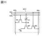
- FIG. 11 is a diagram showing a configuration example of a semiconductor device.
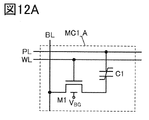
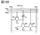
- 12A and 12B are diagrams showing a configuration example of a semiconductor device.
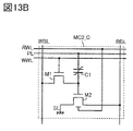
- 13A and 13B are diagrams showing a configuration example of a semiconductor device.
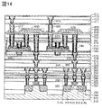
- FIG. 14 is a schematic cross-sectional view showing a configuration example of a semiconductor device.
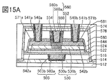
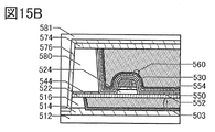
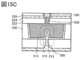
- 15A to 15C are schematic cross-sectional views showing a configuration example of a transistor.
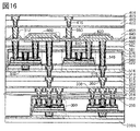
- FIG. 16 is a schematic cross-sectional view showing a configuration example of a semiconductor device.
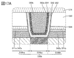
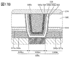
- 17A and 17B are schematic cross-sectional views showing a configuration example of a transistor.
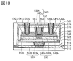
- FIG. 18 is a schematic cross-sectional view showing a configuration example of a transistor.
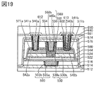
- FIG. 19 is a schematic cross-sectional view showing a configuration example of a transistor.
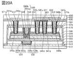
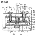
- 20A and 20B are schematic cross-sectional views showing a configuration example of a transistor.
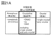
- 21A is a diagram for explaining the classification of the crystal structure of IGZO
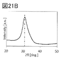
- FIG. 21B is a diagram for explaining the XRD spectrum of crystalline IGZO
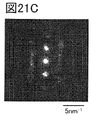
- FIG. 21C is a diagram for explaining the microelectron diffraction pattern of crystalline IGZO.
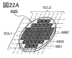
- FIG. 22A is a perspective view showing an example of a semiconductor wafer.
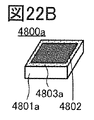
- FIG. 22B is a perspective view showing an example of the chip.
- 22C and 22D are perspective views showing an example of an electronic component.
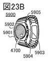
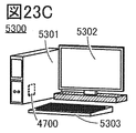
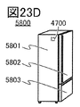
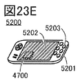
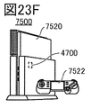
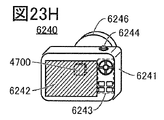
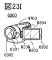
- 23A to 23J are diagrams illustrating an example of an electronic device.
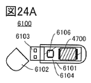
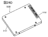
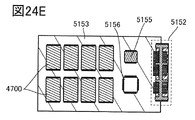
- 24A to 24E are diagrams illustrating an example of an electronic device.
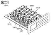
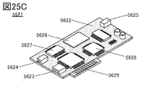
- 25A to 25C are diagrams illustrating an example of an electronic device.
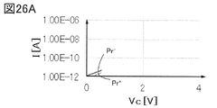
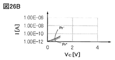
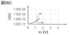
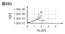
- 26A to 26D are diagrams illustrating measurement data.
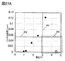
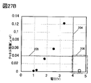
- 27A and 27B are graphs showing a configuration example of a semiconductor device.
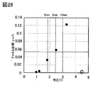
- FIG. 28 is a graph showing a configuration example of a semiconductor device.
- the ordinal numbers "1st”, “2nd”, and “3rd” are added to avoid confusion of the components. Therefore, the number of components is not limited. Moreover, the order of the components is not limited. Further, for example, the component referred to in “first” in one of the embodiments of the present specification or the like is referred to as another embodiment or the component referred to in “second” in the scope of claims. It is possible. Further, for example, the component referred to in “first” in one of the embodiments of the present specification and the like may be omitted in another embodiment or in the scope of claims.
- a metal oxide is a metal oxide in a broad sense. Metal oxides are classified into oxide insulators, oxide conductors (including transparent oxide conductors), oxide semiconductors (also referred to as Oxide Semiconductor or simply OS) and the like. For example, when a metal oxide is used for the active layer of a transistor, the metal oxide may be referred to as an oxide semiconductor. That is, when a metal oxide can form a channel forming region of a transistor having at least one of an amplification action, a rectifying action, and a switching action, the metal oxide can be referred to as a metal oxide semiconductor. can. Further, in the case of describing as an OS FET or an OS transistor, it can be paraphrased as a transistor having a metal oxide or an oxide semiconductor.
- a semiconductor device having a memory cell can be called a storage device.
- the memory cell has a function of holding data.
- the memory cell has a capacitor (capacity).
- the capacitor has a structure having a ferroelectric layer between the first electrode and the second electrode.
- a capacitor provided with a ferroelectric layer may be referred to as a ferroelectric capacitor (ferroelectric capacitance).
- a ferroelectric capacitor In a ferroelectric capacitor, when a voltage (electric field or electric field) is applied between the electrodes, the polarization direction and the amount of polarization of the ferroelectric layer change according to the application direction and amount of the voltage. A signal (data) is stored (written) in a memory cell provided with a ferroelectric capacitor by utilizing a change in the polarization state of the ferroelectric layer. In a ferroelectric capacitor, polarization remains in the ferroelectric layer even if the voltage between the electrodes is zero (residual polarization). In order to rewrite the polarization, a voltage for reversing the polarization (polarization inversion) (polarization inversion voltage) is applied.
- polarization inversion polarization inversion voltage
- a method for driving a semiconductor device capable of reading data from the memory cell without performing destructive reading is used.
- the read operation is performed so that the voltage on the counter electrode side of the ferroelectric capacitor is gradually increased so that the polarization of the ferroelectric capacitor is not destroyed.
- the operation of reading data from the memory cell is performed by applying a voltage to the ferroelectric capacitor so as not to invert the polarization of the ferroelectric layer.
- the subsequent operation of reading data from the memory cell is a driving method in which the voltage is set to a voltage higher than the voltage applied in the previous read operation as a voltage that does not cause the ferroelectric layer to be polarized and inverted in the ferroelectric capacitor. ..
- the semiconductor device of one aspect of the present invention in order to apply a voltage not exceeding the polarization inversion voltage to the ferroelectric capacitor in the data readout operation, the polarization direction of the residual polarization of the ferroelectric layer is maintained before and after the data readout. Can be done. Therefore, the semiconductor device of one aspect of the present invention can retain data for a long period of time. As a result, the frequency of refreshing (rewriting data to the memory cell) can be reduced, so that the power consumption of the semiconductor device according to one aspect of the present invention can be reduced. Further, the ferroelectric capacitor provided with the ferroelectric layer between the electrodes can hold data for a long time without adopting a structure for increasing the capacitance, for example, a trench structure. This makes it possible to obtain a semiconductor device having a structure that is easy to make.
- FIG. 1A is a circuit diagram of a memory cell MC having a ferroelectric capacitor.
- the memory cell MC is also referred to as a cell.
- the memory cell MC has a transistor M1 and a ferroelectric capacitor C1.
- the ferroelectric capacitor C1 is schematically shown as a capacitor having a ferroelectric layer FE between the electrode UE and the electrode LE.
- the read operation of the memory cell MC is performed by wiring WL (also referred to as a word line) in a state where the wiring BL (also referred to as a bit line) connected to the transistor M1 is electrically suspended at a predetermined potential.
- the transistor M1 is brought into a conductive state (on), and the voltage of the wiring PL (also referred to as a plate wire) on the electrode UE side is changed.
- the potential of the wiring BL changes due to the capacitive coupling of the ferroelectric capacitor. Since the change in the potential of the wiring BL changes depending on the polarization state of the ferroelectric layer in the ferroelectric capacitor, the potential corresponding to the written data can be read out to the wiring BL.
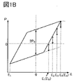
- FIG. 1B is a graph showing the magnitude (polarization amount) of polarization depending on the electric field on the ferroelectric layer FE.
- the change in the polarization of the ferroelectric layer FE with respect to the electric field is shown by a straight line for easy understanding, but the measured data is represented by a curve.
- the horizontal axis shows the electric field E applied to the ferroelectric layer.
- the vertical axis shows the polarization P of the ferroelectric layer.
- the difference between positive and negative polarization when the electric field is 0 is shown as 2PR .
- the polarization of the ferroelectric layer increases.
- E H the electric field applied to the ferroelectric layer and then the electric field applied to the ferroelectric layer is lowered, the positive charge is biased to one electrode side of the capacitance, and the negative charge is biased to the other electrode side of the capacitance. Since it is biased, positive polarization remains when the electric field becomes zero.
- the electric field applied to the ferroelectric layer FE is lowered, the polarization of the ferroelectric layer becomes smaller.
- the voltage for applying the electric field E H and the electric field EL to the ferroelectric layer FE can be said to be a polarization inversion voltage.
- a voltage not exceeding the polarization inversion voltage is applied to the ferroelectric capacitor C1 so that the polarization direction of the residual polarization of the ferroelectric layer FE is maintained.
- the electric field is gradually increased so that the polarization direction of the residual polarization of the ferroelectric layer FE is maintained.
- electric fields E 1 to E 4 that do not exceed the electric field E H exemplified in FIG. 1B are sequentially applied for each read operation.
- the voltage for applying the electric fields E 1 to E 4 applied to the ferroelectric layer FE can be said to be a voltage that does not reverse the polarization.
- so-called destructive reading can be performed.
- the data refreshing operation which is the operation of rewriting the data.
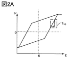
- the degree of change in polarization with respect to the change in electric field TVS is determined. It is preferable that the inclination is positive. Since the degree of change in polarization with respect to the change in electric field is a positive gradient, the voltage for reading data from the memory cell MC during the read operation is preferably larger than the voltage at which the polarization of the ferroelectric layer FE is set to 0.
- the change in polarization is not large with respect to the change in electric field.
- the degree of change in the residual polarization for each readout operation is achieved in the case of an operation in which the polarization direction of the residual polarization of the ferroelectric layer FE is not completely reversed but is partially reversed. Can be made smaller.
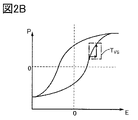
- the graph of the electric field and the polarization in the actual ferroelectric layer changes in a curve as shown in FIG. 2B.
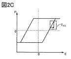
- the slope such as TVS described above can be expressed as the slope of the tangent line. It is also effective in the case of the shape of the graph shown in FIG. 2C.
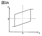
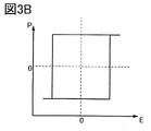
- the degree of change (slope) of the polarization with respect to the change of the electric field is as shown in the shape of the graph showing the magnitude of the polarization according to the electric field shown in FIG. 3A. It is not preferable when the slope is positive and the change in polarization is large with respect to the change in the electric field, and the slope becomes steep. In this case, the degree of change in polarization with respect to the change in electric field becomes large, and it becomes difficult to operate so as to partially reverse the polarization direction of the residual polarization of the ferroelectric layer FE. As shown in FIG. 3B, the same can be said for the shape of the graph as in FIG. 3A.
- hafnium oxide, zirconium oxide, and cerium oxide examples include hafnium oxide, zirconium oxide, and cerium oxide.
- hafnium oxide and element J1 the element J1 here is zirconium (Zr), silicon (Si), aluminum (Al), gadolinium (Gd), yttrium (Y), A material to which lanthanum (La), strontium (Sr), etc.) is added
- element J2 element J2 here is hafnium (Hf), silicon (Si), aluminum (Al), gadolinium (Gd)
- hafnium oxide zirconium (HfZrO X hafnium oxide zirconium (HfZrO X : X is a real number larger than 0) in which zirconium is added to hafnium oxide is preferable.
- barium titanate BST
- strontium titanate PZT
- strontium bismuthate tantanate SBT
- bismuth ferrite BFO
- Barium titanate for example, a laminated structure composed of a plurality of materials selected from the materials listed above or a plurality of materials selected from the materials listed above may be used. can.
- the crystal structure (characteristics) of hafnium oxide, zirconium oxide, HfZrOX , and materials obtained by adding the element J1 to hafnium oxide may change not only depending on the film forming conditions but also depending on various processes.
- a material exhibiting ferroelectricity is not only referred to as a ferroelectric substance, but is also referred to as a material capable of having ferroelectricity or a material having a ferroelectricity.
- aluminum nitride scandium Al 1-a Sc a N b (a is a real number larger than 0 and smaller than 0.5, and b is a value of 1 or its vicinity).
- Al-Ga-Sc nitride Al-Ga-Sc nitride
- Ga-Sc nitride examples of the material having a ferroelectricity include a metal nitride having an element M1, an element M2, and nitrogen.
- the element M1 is one or a plurality selected from aluminum (Al), gallium (Ga), indium (In) and the like.
- the element M2 is boron (B), scandium (Sc), yttrium (Y), lanthanum (La), cerium (Ce), neodymium (Nd), europium (Eu), titanium (Ti), zirconium (Zr). , Hafnium (Hf), vanadium (V), niobium (Nb), tantalum (Ta), chromium (Cr) and the like.
- the ratio of the number of atoms of the element M1 to the number of atoms of the element M2 can be appropriately set. Further, the metal oxide having the element M1 and nitrogen may have ferroelectricity even if the element M2 is not contained.
- Examples of the material having a ferroelectricity include a material in which the element M3 is added to the metal nitride.
- the element M3 is one or a plurality selected from magnesium (Mg), calcium (Ca), strontium (Sr), zinc (Zn), cadmium (Cd) and the like.
- Mg magnesium
- Ca calcium
- Zn zinc
- Cd cadmium
- the ratio of the number of atoms of the element M1, the number of atoms of the element M2, and the number of atoms of the element M3 can be appropriately set.
- the metal nitride contains at least a group 13 element and nitrogen which is a group 15 element, the metal nitride is used as a group 13-15 strong dielectric and a group 13. It may be called a strong dielectric of a nitride.
- HfZrOX is preferable as a material used for the ferroelectric layer because it can have ferroelectricity even when processed into a thin film of several nm.
- the film thickness of the ferroelectric layer can be 100 nm or less, preferably 50 nm or less, more preferably 20 nm or less, still more preferably 10 nm or less (typically 2 nm or more and 9 nm or less).
- HfZrOX When used as a material capable of having ferroelectricity, it is preferable to form a film by using an atomic layer deposition (ALD) method, particularly a thermal ALD method. Further, when a material capable of having ferroelectricity is formed by using the thermal ALD method, it is preferable to use a material containing no hydrocarbon (also referred to as Hydro Carbon, HC) as a precursor. When one or both of hydrogen and carbon are contained in the material which may have a ferroelectricity, the crystallization of the material which may have a ferroelectricity may be inhibited.
- ALD atomic layer deposition
- HC Hydro Carbon
- a precursor containing no hydrocarbon a chlorine-based material can be mentioned.
- HfZrO x hafnium oxide and zirconium oxide
- HfCl 4 and / or ZrCl 4 may be used as the precursor.
- high-purity intrinsicity is achieved by thoroughly eliminating at least one of impurities, here hydrogen, hydrocarbon, and carbon in the film. It is possible to form a film having a strong ferroelectricity. It should be noted that the film having high-purity intrinsic ferroelectricity and the high-purity intrinsic oxide semiconductor shown in the embodiment described later have very high consistency in the manufacturing process. Therefore, it is possible to provide a method for manufacturing a semiconductor device having high productivity.
- HfZrOX is used as a material capable of having ferroelectricity
- the oxidizing agent of the thermal ALD method is not limited to this.
- the oxidizing agent in the thermal ALD method may contain one or more selected from O 2 , O 3 , N 2 O, NO 2 , H 2 O, and H 2 O 2 .
- the crystal structure of the material that can have ferroelectricity is not particularly limited.
- the crystal structure of the material that may have strong dielectric property may be one or more selected from cubic, tetragonal, orthorhombic, and monoclinic.
- a material capable of having ferroelectricity it is preferable to have an orthorhombic crystal structure because ferroelectricity is exhibited.
- a composite structure having an amorphous structure and a crystal structure may be used as a material capable of having ferroelectricity.
- FIG. 4 is a block diagram showing a configuration example of the semiconductor device 10 which is the semiconductor device of one aspect of the present invention.
- the semiconductor device 10 can be, for example, a storage device.
- the semiconductor device 10 is provided with a memory cell array MCA in which m rows and n columns (m and n are integers of 1 or more) are arranged in a matrix. Further, the semiconductor device 10 includes a word line drive circuit WD, a plate line drive circuit PD, a potential generation circuit SD, and a bit line drive circuit BD.
- the word line drive circuit WD is electrically connected to the memory cell MC via the wiring WL, and is also electrically connected to the memory cell MC via the wiring RWL.
- the plate wire drive circuit PD is electrically connected to the memory cell MC via the wiring PL.
- the bit line drive circuit BD is electrically connected to the memory cell MC via the wiring BL.
- the memory cells MC in the same row can be electrically connected to the word line drive circuit WD via the same wiring WL, and can be electrically connected to the plate wire drive circuit PD via the same wiring PL. can do. Further, the memory cells MC in the same row can be electrically connected to the bit line drive circuit BD via the same wiring BL.
- the memory cell MC in the first row and the first column is described as the memory cell MC [1,1]
- the memory cell MC in the mth row and the nth column is referred to as the memory cell MC [m, n].
- the wiring WL and the wiring PL electrically connected to the memory cell MC in the first row are described as the wiring WL [1] and the wiring PL [1], respectively, and are referred to as the memory cell MC in the mth row.
- the electrically connected wiring WL and wiring PL are described as wiring WL [m] and wiring PL [m], respectively.
- wiring BL electrically connected to the memory cell MC in the first row is described as wiring BL [1]
- wiring BL electrically connected to the memory cell MC in the nth row is designated as wiring BL [1]. It is described as wiring BL [n].
- the same description may be made for other elements.
- the word line drive circuit WD has a function of controlling the potential of the wiring WL. Specifically, the word line drive circuit WD has a function of selecting a memory cell MC to write data by controlling the potential of the wiring WL.
- the plate wire drive circuit PD has a function of controlling the potential of the wiring PL.
- the bit line drive circuit BD has a function of generating data to be written in the memory cell MC and supplying the data to the memory cell MC in a predetermined column. Further, the bit line drive circuit BD has a function of reading and outputting the data written in the memory cell MC.
- the bit line drive circuit BD has a sense amplifier circuit SA [1] to a sense amplifier circuit SA [n].
- the sense amplifier circuit SA is electrically connected to the wiring BL, the wiring REF, the wiring EL, and the wiring PRE. Further, the sense amplifier circuit SA [1] to the sense amplifier circuit SA [n] are electrically connected to the wiring OUT [1] to the wiring OUT [n].
- the sense amplifier circuit SA has a function of amplifying the difference between the potential of the wiring BL and the potential of the wiring REF. For example, when the potential of the wiring BL is higher than the potential of the wiring REF, the sense amplifier circuit SA can output a high potential. On the other hand, when the potential of the wiring BL is lower than the potential of the wiring REF, the sense amplifier circuit SA can output a low potential. As a result, the bit line drive circuit BD can write binary data, specifically binary digital data, to the memory cell MC, and can read the binary data written to the memory cell MC. For example, when the potential of the wiring BL is higher than the potential of the wiring REF, it can be assumed that "0" is written to the memory cell MC or "0" is read. On the other hand, when the potential of the wiring BL is lower than the potential of the wiring REF, it can be assumed that "1" is written to the memory cell MC or "1" is read.
- An enable signal that controls whether or not to activate the sense amplifier circuit SA can be supplied to the wiring EL.
- the enable signal can be, for example, a binary digital signal.
- the sense amplifier circuit SA can be activated, and the difference between the potential of the wiring BL and the potential of the wiring REF is amplified.
- the sense amplifier circuit SA can be in the deactivated state, and the above amplification is not performed.
- the wiring PRE can be supplied with a precharge signal that controls whether or not to precharge the potentials of the wiring BL and the wiring REF.
- the precharge signal can be, for example, a binary digital signal.
- the potential of the wiring PRE is high, the wiring BL can be precharged to a high potential.
- the potential of the wiring REF is the potential of the wiring BL when the data having a value of "0" is read from the memory cell MC, and the data having a value of "1" is read from the memory cell MC. It can be a potential between the potential of the wiring BL in the case.
- the potentials supplied to the wiring EL [1] to the wiring EL [n] may be common to each other.
- the wiring EL [1] to the wiring EL [n] can be configured to be electrically connected to each other.
- the potentials supplied to the wiring PRE [1] to the wiring PRE [n] may be common to each other.
- the wiring PRE [1] to the wiring PRE [n] can be configured to be electrically connected to each other.
- the data output from the sense amplifier circuit SA is output from the wiring OUT.
- the data of the sense amplifier circuit SA [1] can be output from the wiring OUT [1].
- the data of the sense amplifier circuit SA [n] can be output from the wiring OUT [n].
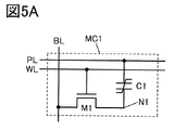
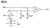
- FIG. 5A shows a circuit diagram of a memory cell applicable to the memory cell MC1 of FIG.
- the memory cell MC1 has a transistor M1 and a ferroelectric capacitor C1.
- each element of the transistor M1 and the ferroelectric capacitor C1 is connected to the wiring BL, the wiring PL, and / or the wiring WL as shown in FIG. 5A.
- the wiring for electrically connecting the transistor M1 and the ferroelectric capacitor C1 is shown as a node N1.
- FIG. 5B is a diagram illustrating the electrical connection between each configuration of the transistor M1 and the ferroelectric capacitor C1 included in the memory cell MC1 and the sense amplifier circuit SA.
- Wiring BL, wiring REF, and wiring OUT are connected to the sense amplifier circuit SA as shown in FIG. 5B.
- the sense amplifier circuit SA amplifies the difference between the potential of the wiring BL and the potential of the wiring REF.
- the potential or voltage of the wiring REF is also referred to as a reference potential or reference voltage.
- Loads CBL and CREF which are parasitic capacitances, are assigned to the wiring BL and the wiring REF, respectively. Loads CBL and CREF are provided as equivalent loads.
- the configuration shown in FIG. 5B is the same as the description of FIG. 5A.
- Data is written to the memory cell MC1 by applying a voltage to the ferroelectric capacitor C1.
- the ferroelectric substance in the ferroelectric capacitor C1 is polarized to the state "1". do.
- the ferroelectric substance in the ferroelectric capacitor C1 is polarized to the state “0”.
- the voltage applied to the node N1 and the wiring PL may be 0V for the L level, 2.5V or 3.3V for the H level, or the like.
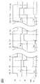
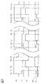
- FIGS. 5A and 5B show timing charts when the read operation of one aspect of the present invention is applied to the memory cells MC1 shown in FIGS. 5A and 5B.
- FIG. 6 shows the case where the ferroelectric substance in the ferroelectric capacitor C1 is polarized to the state “0”
- FIG. 7 shows the case where the ferroelectric substance in the ferroelectric capacitor C1 is polarized to the state “1”.
- It is a timing chart of the data reading operation.
- the transistor M1 is turned on by setting the wiring WL to the H level at time T0.
- the voltage of the wiring BL is boosted by the capacitive coupling via the ferroelectric capacitor C1.
- the reference voltage of the wiring REF is set to the voltage Va'corresponding to the voltage Va'.
- the voltage of the wiring BL after boosting is smaller than the voltage of the wiring REF.
- the voltage of the wiring BL after boosting is larger than the voltage of the wiring REF.
- the voltage for reading data does not exceed the polarization inverting voltage in the configuration of one aspect of the present invention. Therefore, the polarization direction of the ferroelectric layer is maintained before and after the readout operation. Therefore, it is possible to eliminate the need to apply a high voltage for writing back data.
- the wiring PL and wiring EL are set to L level.
- the sense amplifier circuit SA becomes inactive.
- the transistor M1 is turned off and the read operation is completed.
- the second read operation is performed after the time T5.
- the wiring WL At time T5, set the wiring WL to H level and turn on the transistor M1.
- the voltage of the wiring BL is boosted by the capacitive coupling via the ferroelectric capacitor C1.
- the reference voltage of the wiring REF is set to the voltage Vb'(> voltage Va') corresponding to the voltage Vb.
- the ferroelectric capacitor C1 since the ferroelectric capacitor C1 is polarized to the state “0”, the voltage of the wiring BL after boosting is smaller than the voltage of the wiring REF.
- the ferroelectric capacitor C1 since the ferroelectric capacitor C1 is polarized to the state “1”, the voltage of the wiring BL after boosting is larger than the voltage of the wiring REF.
- the sense amplifier circuit SA By setting the wiring EL to H level at time T7, the sense amplifier circuit SA is activated. When the wiring EL becomes H level, the sense amplifier circuit SA amplifies the potential difference between the wiring REF and the wiring BL. A signal corresponding to this potential difference is output to the wiring OUT.
- the wiring PL and wiring EL are set to L level, and the sense amplifier circuit SA becomes inactive.
- the transistor M1 is turned off and the read operation is completed.
- the wiring WL At time T10, set the wiring WL to H level and turn on the transistor M1.
- the wiring PL By setting the wiring PL to the voltage Vc (> voltage Vb) at the time T11, the voltage of the wiring BL is boosted by the capacitive coupling via the ferroelectric capacitor C1.
- the reference voltage of the wiring REF is set to the voltage Vc'(> voltage Vb') corresponding to the voltage Vc.
- the ferroelectric capacitor C1 since the ferroelectric capacitor C1 is polarized to the state “0”, the voltage of the wiring BL after boosting is smaller than the voltage of the wiring REF.
- the ferroelectric capacitor C1 since the ferroelectric capacitor C1 is polarized to the state “1”, the voltage of the wiring BL after boosting is larger than the voltage of the wiring REF.
- the sense amplifier circuit SA By setting the wiring EL to H level at time T12, the sense amplifier circuit SA is activated. When the wiring EL becomes H level, the sense amplifier circuit SA amplifies the potential difference between the wiring REF and the wiring BL. A signal corresponding to this potential difference is output to the wiring OUT.
- the wiring PL and wiring EL are set to L level, and the sense amplifier circuit SA becomes inactive.
- the transistor M1 is turned off and the read operation is completed.
- the write-back operation to the ferroelectric capacitor C1 is not performed a plurality of times. Read operation can be realized.
- the voltage of the wiring PL is increased by a certain voltage or more (for example, 3.3 V), it is preferable to perform a data refresh operation.
- a high voltage is applied to the ferroelectric capacitor C1 to perform a data refresh operation.
- the OS transistor has excellent withstand voltage, it is possible to miniaturize each element of the memory cell by using it in combination with a ferroelectric capacitor having a high drive voltage. Further, since the OS transistor has a feature that the off current is extremely small, it is possible to hold the voltage of the node N1 for a long time. Here, there is a concern that the voltage of the node N1 may be stepped down by a leak via the ferroelectric capacitor C1, but if the electric field applied to the ferroelectric capacitor C1 is small, the leak current can be suppressed. can.
- the charge held in the node N1 can be distributed to the wiring BL, and the change in potential can be amplified by the sense amplifier to read the data.
- the wiring PL may be set to 3.0 V or more and the electric charge may be replenished to the node N1 via the ferroelectric capacitor C1.
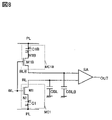
- FIG. 8 shows a configuration example different from the configuration of FIG. 5B.
- FIG. 8 is a diagram illustrating an electrical connection between the memory cell MC1 and the memory cell MC1B in which the inverted data of the data written in the memory cell MC1 is stored, and the sense amplifier circuit SA.
- FIG. 8 illustrates a transistor M1B, a ferroelectric capacitor C1B, and a node N1B as a configuration of the memory cell MC1B which is paired with the configuration of the memory cell MC1.
- the memory cell MC1B is also referred to as a reference memory cell.
- a method of reading data from a memory cell that stores paired data is referred to as a twin cell type.
- FIG. 6 illustrates the wiring BLB to which the memory cell MC1B is connected.
- the sense amplifier circuit SA amplifies the difference between the potential of the wiring BL and the potential of the wiring BLB.
- Loads CBL and CBLB which are parasitic capacitances, are applied to the wiring BL and the wiring BLB, respectively. Loads CBL and CBLB are provided as equivalent loads.
- FIG. 9 and 10 show timing charts when the read operation of one aspect of the present invention is applied to the memory cells MC1 and MC1B shown in FIG.
- FIG. 9 shows the case where the ferroelectric substance in the ferroelectric capacitor C1 is polarized to the state “0”
- FIG. 10 shows the case where the ferroelectric substance in the ferroelectric capacitor C1 is polarized to the state “1”.
- It is a timing chart of the data reading operation.
- the ferroelectric substance in the ferroelectric capacitor C1B is polarized in a state different from that of the ferroelectric capacitor C1.
- the circuit configuration shown in FIG. 8 is a twin cell type, there is no wiring REF shown in FIG. 5B. Therefore, it is not necessary to change the reference voltage of the wiring REF according to the voltage of the wiring PL.
- the precharge of the wiring BL and the wiring BLB may be set to, for example, an L level potential. Since the circuit configuration of FIG. 8 is a twin cell type, inverted data is written in the memory cell MC1 and the memory cell MC1B.
- the transistor M1 and the transistor M1B are turned on by setting the wiring WL to the H level at time T0.
- the wiring PL By setting the wiring PL to the voltage Va at time T1, the voltages of the wiring BL and the wiring BLB are boosted by the capacitive coupling via the ferroelectric capacitor C1 and the ferroelectric capacitor C1B.
- the voltage of the wiring BL after boosting is the wiring. It is smaller than the voltage of BLB.
- the ferroelectric capacitor C1 since the ferroelectric capacitor C1 is polarized to the state "1” (the ferroelectric capacitor C1B is polarized to the state “0”), the voltage of the wiring BL after boosting is the wiring BLB. Greater than the voltage of.
- the wiring EL is an enable signal of the sense amplifier circuit SA, and the sense amplifier circuit SA is activated by reaching the H level.
- the wiring EL becomes the H level, the potential difference between the wiring BLB and the wiring BL is amplified. A signal corresponding to this potential difference is output to the wiring OUT.
- the voltage for reading data does not exceed the polarization inverting voltage in the configuration of one aspect of the present invention. Therefore, the polarization direction of the ferroelectric layer is maintained before and after the readout operation. Therefore, it is possible to eliminate the need to apply a high voltage for writing back data.
- the wiring PL and wiring EL become L level, and the sense amplifier circuit SA becomes inactive.
- the transistor M1 and the transistor M1B are turned off, and the read operation is completed.
- the second read operation is performed after the time T5.
- Transistor M1 and transistor M1B are turned on by setting the wiring WL to H level at time T5.
- the wiring PL By setting the wiring PL to the voltage Vb (> voltage Va) at time T6, the voltages of the wiring BL and the wiring BLB are boosted by the capacitive coupling via the ferroelectric capacitor C1 and the ferroelectric capacitor C1B.
- the voltage of the wiring BL after boosting is the wiring. It is smaller than the voltage of BLB.
- the ferroelectric capacitor C1 since the ferroelectric capacitor C1 is polarized to the state "1” (the ferroelectric capacitor C1B is polarized to the state “0”), the voltage of the wiring BL after boosting is the wiring. It is larger than the voltage of BLB.
- the sense amplifier circuit SA By setting the wiring EL to H level at time T7, the sense amplifier circuit SA is activated. When the wiring EL becomes the H level, the sense amplifier circuit SA amplifies the potential difference between the wiring BLB and the wiring BL. A signal corresponding to this potential difference is output to the wiring OUT.
- the wiring PL and wiring EL are set to L level, and the sense amplifier circuit SA becomes inactive.
- the transistor M1 and the transistor M1B are turned off, and the read operation is completed.
- Transistor M1 and transistor M1B are turned on by setting the wiring WL to H level at time T11.
- the wiring PL By setting the wiring PL to the voltage Vc (> voltage Vb) at the time T12, the voltages of the wiring BL and the wiring BLB are boosted by the capacitive coupling via the ferroelectric capacitor C1 and the ferroelectric capacitor C1B.
- the voltage of the wiring BL after boosting is the wiring. It is smaller than the voltage of BLB.
- the ferroelectric capacitor C1 since the ferroelectric capacitor C1 is polarized to the state "1” (the ferroelectric capacitor C1B is polarized to the state “0”), the voltage of the wiring BL after boosting is the wiring. It is larger than the voltage of BLB.
- the sense amplifier circuit SA By setting the wiring EL to H level at time T12, the sense amplifier circuit SA is activated. When the wiring EL becomes the H level, the sense amplifier circuit SA amplifies the potential difference between the wiring BLB and the wiring BL. A signal corresponding to this potential difference is output to the wiring OUT.
- the wiring PL and wiring EL are set to L level, and the sense amplifier circuit SA becomes inactive.
- the transistor M1 and the transistor M1B are turned off, and the read operation is completed.
- the voltage of the wiring PL is increased by a certain voltage or more (for example, 3.3 V), it is preferable to perform a data refresh operation.
- a high voltage is applied to the ferroelectric capacitor C1 and the ferroelectric capacitor C1B to perform a data refresh operation.
- transistor M1 in FIGS. 5A and 5B Similar to the transistor M1 in FIGS. 5A and 5B, it is effective to use a transistor (OS transistor) having an oxide semiconductor in the channel forming region in the transistors M1 and M1B in FIG.
- FIG. 11 shows a circuit diagram of a memory cell different from the memory cell MC1 described above.
- the memory cell MC2 of FIG. 11 has a transistor M1, a transistor M2, a transistor M3, and a ferroelectric capacitor C1.
- each element of the transistors M1 to M3 and the strong dielectric capacitor C1 has wiring WBL (also referred to as a write bit line), wiring RBL (also referred to as a read bit line), wiring PL, and wiring SL (also referred to as a source line). ), Wiring WWL (also referred to as write word line), and / or wiring RWL (also referred to as read word line) are connected as shown in FIG.
- the wiring for electrically connecting the transistor M1, the transistor M2, and the ferroelectric capacitor C1 is illustrated as a node SN.
- the potential of the node SN changes due to the capacitive coupling of the ferroelectric capacitor C1 by changing the voltage of the wiring PL.
- this difference can be amplified and read by the transistor M2.
- a high voltage for example, 3.3V
- the wiring RBL has a low voltage (for example, 1.2V or less). Data can be read out with.
- the read circuit connected to the wiring RBL has a function of adjusting the read voltage range according to the number of reads.
- the transistors M1 and M3 in FIG. 11 it is effective to use a transistor (OS transistor) having an oxide semiconductor in the channel forming region. Since the OS transistor has a feature that the off current is extremely small, it is possible to hold the voltage of the node SN for a long time. Here, there is a concern that the voltage of the node SN may be stepped down due to leakage through the ferroelectric capacitor C1, but if the electric field applied to the ferroelectric capacitor C1 is small, the leakage current can be suppressed.
- OS transistor transistor having an oxide semiconductor in the channel forming region. Since the OS transistor has a feature that the off current is extremely small, it is possible to hold the voltage of the node SN for a long time.
- the voltage of the node SN may be stepped down due to leakage through the ferroelectric capacitor C1, but if the electric field applied to the ferroelectric capacitor C1 is small, the leakage current can be suppressed.
- the wiring PL may be set to 3.0 V or more to replenish the electric charge in the node SN via the ferroelectric capacitor C1.
- FIG. 12A is a circuit diagram showing a modification of the memory cell MC1 described above.
- the memory cell MC1_A shown in FIG. 12A illustrates a configuration in which the transistor M1 in the memory cell MC1 of FIG. 5A has a back gate electrode to which a back gate voltage VBG is applied. With the configuration of FIG. 12A, the amount of current flowing through each transistor can be increased.
- FIG. 12B is a circuit diagram showing a modified example of the memory cell MC2 described above.
- the memory cell MC2_A shown in FIG. 12B illustrates a configuration in which the transistors M1 to M3 in the memory cell MC2 of FIG. 11 have a back gate electrode to which a back gate voltage VBG is applied.
- VBG back gate voltage
- the backgate voltage applied to the backgate of each transistor may be the same voltage or may be different.
- FIG. 13A is a circuit diagram showing a modified example of the memory cell MC2 described above.
- the memory cell MC2_B shown in FIG. 13A illustrates a configuration in which the wiring WBL and the wiring RBL in the memory cell MC2 of FIG. 11 are shared as a wiring BL. With the configuration of FIG. 13A, the number of wires connected to the memory cells can be reduced.
- FIG. 13B is a circuit diagram showing a modified example of the memory cell MC2 described above.
- the memory cell MC2_C shown in FIG. 13B illustrates a circuit diagram in which the transistor M3 in the memory cell MC2 of FIG. 11 is omitted and the wiring RWL is connected to the back gate of the transistor M2.
- the selection signal given to the wiring RWL controls whether or not a current flows between the wiring RWL and the wiring SL by controlling the threshold voltage of the transistor M2. With the configuration shown in FIG. 13B, the number of transistors in the memory cell can be reduced.
- the polarization direction of the residual polarization of the ferroelectric layer FE is not completely reversed, but is partially reversed. It works like this. Since the balance of the polarization direction of the residual polarization of the ferroelectric layer FE is lost through the readout operation, in this operation, the voltage on the opposite electrode side of the ferroelectric capacitor is stepped so that the polarization of the ferroelectric capacitor is not destroyed. The read operation is performed so as to increase the size. With this configuration, data can be read out even if the residual polarization of the ferroelectric layer FE becomes small due to repeated reading operations.
- Embodiment 2 In this embodiment, a configuration example of a transistor applicable to the semiconductor device described in the above embodiment will be described. As an example, a configuration in which transistors having different electrical characteristics are laminated and provided will be described. With this configuration, the degree of freedom in designing the semiconductor device can be increased. Further, by stacking transistors having different electrical characteristics, the degree of integration of the semiconductor device can be increased.
- FIG. 14 shows, as an example, the semiconductor device described in the above embodiment, in which the semiconductor device includes a transistor 300, a transistor 500, and a capacitive element 600.
- 15A shows a cross-sectional view of the transistor 500 in the channel length direction
- FIG. 15B shows a cross-sectional view of the transistor 500 in the channel width direction
- FIG. 15C shows a cross-sectional view of the transistor 300 in the channel width direction.
- the transistor 500 is a transistor (OS transistor) having a metal oxide in the channel forming region.
- the transistor 500 has a characteristic that the off-current is small and the field effect mobility does not change easily even at a high temperature.
- a semiconductor device for example, the OS transistor described in the above embodiment, it is possible to realize a semiconductor device whose operating ability does not easily decrease even at high temperatures.
- the transistor 500 is provided above the transistor 300, for example, and the capacitive element 600 is provided above the transistor 300 and the transistor 500, for example.
- the transistor 300 is provided on the substrate 310, and has an element separation layer 312, a conductor 316, an insulator 315, a semiconductor region 313 including a part of the substrate 310, a low resistance region 314a functioning as a source region or a drain region, and a low resistance region. It has a resistance region 314b.
- the transistor 300 can be applied to, for example, the Si transistor described in the above embodiment. Note that FIG. 14 shows, as an example, a configuration in which the gate of the transistor 300 is electrically connected to one of the source and drain of the transistor 500 via a pair of electrodes of the capacitive element 600.
- a semiconductor substrate for example, a single crystal substrate or a silicon substrate
- the substrate 310 it is preferable to use a semiconductor substrate (for example, a single crystal substrate or a silicon substrate) as the substrate 310.
- the transistor 300 is covered with the conductor 316 on the upper surface of the semiconductor region 313 and the side surface in the channel width direction via the insulator 315.
- the on characteristic of the transistor 300 can be improved by increasing the effective channel width. Further, since the contribution of the electric field of the gate electrode can be increased, the off characteristic of the transistor 300 can be improved.
- the transistor 300 may be either a p-channel type or an n-channel type.
- a semiconductor such as a silicon-based semiconductor in a region in which a channel of the semiconductor region 313 is formed, a region in the vicinity thereof, a low resistance region 314a serving as a source region or a drain region, a low resistance region 314b, and the like.
- It preferably contains crystalline silicon.
- it may be formed of a material having Ge (germanium), SiGe (silicon germanium), GaAs (gallium arsenide), GaAlAs (gallium aluminum arsenide), GaN (gallium nitride), or the like.
- a configuration using silicon in which the effective mass is controlled by applying stress to the crystal lattice and changing the lattice spacing may be used.
- the transistor 300 may be a HEMT (High Electron Mobility Transistor) by using GaAs and GaAlAs or the like.
- n-type conductivity such as arsenic and phosphorus, or p-type conductivity such as boron are imparted.
- the conductor 316 that functions as a gate electrode is a semiconductor material such as silicon, a metal material, or an alloy containing an element that imparts n-type conductivity such as arsenic or phosphorus, or an element that imparts p-type conductivity such as boron.
- a conductive material such as a material or a metal oxide material can be used.
- the threshold voltage of the transistor can be adjusted by selecting the material of the conductor. Specifically, it is preferable to use a material such as titanium nitride or tantalum nitride for the conductor. Further, in order to achieve both conductivity and embedding property, it is preferable to use a metal material such as tungsten or aluminum as a laminate for the conductor, and it is particularly preferable to use tungsten in terms of heat resistance.
- the element separation layer 312 is provided to separate a plurality of transistors formed on the substrate 310.
- the element separation layer can be formed by using, for example, a LOCOS (LOCOxidation of Silicon) method, an STI (Shallow Trench Isolation) method, a mesa separation method, or the like.
- the transistor 300 shown in FIG. 14 is an example, and the transistor 300 is not limited to its structure, and an appropriate transistor may be used depending on the circuit configuration, driving method, and the like.
- the transistor 300 may have a planar type structure instead of the FIN type shown in FIG. 15C.
- the transistor 300 may be configured in the same manner as the transistor 500 using an oxide semiconductor, as shown in FIG. The details of the transistor 500 will be described later.
- the unipolar circuit means a circuit including a transistor having only one polarity of an n-channel transistor or a p-channel transistor.
- the transistor 300 is provided on the substrate 310A.
- a semiconductor substrate may be used in the same manner as the substrate 310 of the semiconductor device of FIG.
- the substrate 310A includes, for example, an SOI substrate, a glass substrate, a quartz substrate, a plastic substrate, a sapphire glass substrate, a metal substrate, a stainless steel substrate, a substrate having a stainless steel still foil, a tungsten substrate, and a tungsten foil.
- a substrate, a flexible substrate, a laminated film, a paper containing a fibrous material, a base film, or the like can be used.
- glass substrates include barium borosilicate glass, aluminoborosilicate glass, and soda lime glass.
- flexible substrates, laminated films, base films, etc. include the following.
- plastics typified by polyethylene terephthalate (PET), polyethylene naphthalate (PEN), polyether sulfone (PES), and polytetrafluoroethylene (PTFE).
- PET polyethylene terephthalate
- PEN polyethylene naphthalate
- PES polyether sulfone
- PTFE polytetrafluoroethylene
- synthetic resin such as acrylic.
- polypropylene polyester, polyvinyl fluoride, polyvinyl chloride and the like.
- polyamide, polyimide, aramid epoxy resin, inorganic thin-film film, papers and the like.
- the transistor 300 shown in FIG. 14 is provided with an insulator 320, an insulator 322, an insulator 324, and an insulator 326 stacked in this order from the substrate 310 side.
- the insulator 320, the insulator 322, the insulator 324, and the insulator 326 for example, silicon oxide, silicon oxide, silicon nitride, silicon nitride, aluminum oxide, aluminum oxide, aluminum nitride, aluminum nitride, etc. are used. Just do it.
- silicon oxide refers to a material having a higher oxygen content than nitrogen as its composition
- silicon nitride as its composition refers to a material having a higher nitrogen content than oxygen as its composition. Is shown.
- aluminum nitride refers to a material whose composition has a higher oxygen content than nitrogen
- aluminum nitride refers to a material whose composition has a higher nitrogen content than oxygen. Is shown.
- the insulator 322 may have a function as a flattening film for flattening a step generated by the insulator 320 and the transistor 300 covered with the insulator 322.
- the upper surface of the insulator 322 may be flattened by a flattening treatment using a chemical mechanical polishing (CMP) method or the like in order to improve the flatness.
- CMP chemical mechanical polishing
- the insulator 324 it is preferable to use a film having a barrier property so that hydrogen, impurities, etc. do not diffuse in the region where the transistor 500 is provided from the substrate 310, the transistor 300, or the like.
- a film having a barrier property against hydrogen for example, silicon nitride formed by the CVD method can be used.
- hydrogen may diffuse into a semiconductor element having an oxide semiconductor such as a transistor 500, which may deteriorate the characteristics of the semiconductor element. Therefore, it is preferable to use a film that suppresses the diffusion of hydrogen between the transistor 500 and the transistor 300.
- the membrane that suppresses the diffusion of hydrogen is a membrane that desorbs a small amount of hydrogen.
- the amount of hydrogen desorbed can be analyzed using, for example, a heated desorption gas analysis method (TDS).
- TDS heated desorption gas analysis method
- the amount of hydrogen desorbed from the insulator 324 is the amount desorbed in terms of hydrogen atoms in the range of 50 ° C. to 500 ° C. in the surface temperature of the film, which is converted into the area of the insulator 324. It may be 10 ⁇ 10 15 atoms / cm 2 or less, preferably 5 ⁇ 10 15 atoms / cm 2 or less.
- the insulator 326 has a lower dielectric constant than the insulator 324.
- the relative permittivity of the insulator 326 is preferably less than 4, more preferably less than 3.
- the relative permittivity of the insulator 326 is preferably 0.7 times or less, more preferably 0.6 times or less the relative permittivity of the insulator 324.
- the insulator 320, the insulator 322, the insulator 324, and the insulator 326 are embedded with a capacitive element 600, a conductor 328 connected to the transistor 500, a conductor 330, and the like.
- the conductor 328 and the conductor 330 have a function as a plug or wiring.
- a plurality of structures may be collectively given the same reference numeral.
- the wiring and the plug connected to the wiring may be integrated. That is, a part of the conductor may function as a wiring, and a part of the conductor may function as a plug.
- each plug and wiring As the material of each plug and wiring (conductor 328, conductor 330, etc.), a conductive material such as a metal material, an alloy material, a metal nitride material, or a metal oxide material is used as a single layer or laminated. be able to. It is preferable to use a refractory material such as tungsten or molybdenum that has both heat resistance and conductivity, and it is preferable to use tungsten. Alternatively, it is preferably formed of a low resistance conductive material such as aluminum or copper. Wiring resistance can be reduced by using a low resistance conductive material.
- a wiring layer may be provided on the insulator 326 and the conductor 330.
- the insulator 350, the insulator 352, and the insulator 354 are provided in order above the insulator 326 and the conductor 330 in order.
- a conductor 356 is formed on the insulator 350, the insulator 352, and the insulator 354.
- the conductor 356 has a function as a plug or wiring for connecting to the transistor 300.
- the conductor 356 can be provided by using the same material as the conductor 328 and the conductor 330.
- the insulator 350 it is preferable to use an insulator having a barrier property against impurities such as hydrogen and water, similarly to the insulator 324.
- the insulator 352 and the insulator 354 it is preferable to use an insulator having a relatively low relative permittivity in order to reduce the parasitic capacitance generated between the wirings, similarly to the insulator 326.
- the conductor 356 preferably contains a conductor having a barrier property against impurities such as hydrogen and water.
- a conductor having a barrier property against hydrogen is formed in the opening of the insulator 350 having a barrier property against hydrogen.
- the conductor having a barrier property against hydrogen for example, tantalum nitride or the like may be used. Further, by laminating tantalum nitride and tungsten having high conductivity, it is possible to suppress the diffusion of hydrogen from the transistor 300 while maintaining the conductivity as wiring. In this case, it is preferable that the tantalum nitride layer having a barrier property against hydrogen has a structure in contact with the insulator 350 having a barrier property against hydrogen.
- the insulator 360, the insulator 362, and the insulator 364 are laminated in order on the insulator 354 and the conductor 356.
- the insulator 360 it is preferable to use an insulator having a barrier property against impurities such as water and hydrogen, similarly to the insulator 324 and the like. Therefore, as the insulator 360, for example, a material applicable to the insulator 324 or the like can be used.
- the insulator 362 and the insulator 364 have a function as an interlayer insulating film and a flattening film. Further, as the insulator 362 and the insulator 364, it is preferable to use an insulator having a barrier property against impurities such as water and hydrogen, similarly to the insulator 324. Therefore, as the insulator 362 and / or the insulator 364, a material applicable to the insulator 324 can be used.
- an opening is formed in a region of each of the insulator 360, the insulator 362, and the insulator 364 that overlaps with a part of the conductor 356, and the conductor 366 is provided so as to fill the opening.
- the conductor 366 is also formed on the insulator 362.
- the conductor 366 has a function as a plug or wiring for connecting to the transistor 300.
- the conductor 366 can be provided by using the same material as the conductor 328 and the conductor 330.
- the insulator 510, the insulator 512, the insulator 514, and the insulator 516 are laminated in this order on the insulator 364 and the conductor 366.
- any of the insulator 510, the insulator 512, the insulator 514, and the insulator 516 it is preferable to use a substance having a barrier property against oxygen and hydrogen.
- the insulator 510 and the insulator 514 have a barrier property such that hydrogen and impurities do not diffuse from the region where the substrate 310 or the transistor 300 is provided to the region where the transistor 500 is provided. It is preferable to use. Therefore, the same material as the insulator 324 can be used.
- Silicon nitride formed by the CVD method can be used as an example of a film having a barrier property against hydrogen.
- hydrogen may diffuse into a semiconductor element having an oxide semiconductor such as a transistor 500, which may deteriorate the characteristics of the semiconductor element. Therefore, it is preferable to use a film that suppresses the diffusion of hydrogen between the transistor 500 and the transistor 300.
- the membrane that suppresses the diffusion of hydrogen is a membrane that desorbs a small amount of hydrogen.
- metal oxides such as aluminum oxide, hafnium oxide, and tantalum oxide for the insulator 510 and the insulator 514.
- aluminum oxide has a high blocking effect that does not allow the membrane to permeate both oxygen and impurities such as hydrogen and moisture that cause fluctuations in the electrical characteristics of the transistor. Therefore, aluminum oxide can prevent impurities such as hydrogen and moisture from being mixed into the transistor 500 during and after the manufacturing process of the transistor. In addition, it is possible to suppress the release of oxygen from the oxides constituting the transistor 500. Therefore, it is suitable for use as a protective film for the transistor 500.
- the same material as the insulator 320 can be used for the insulator 512 and the insulator 516. Further, by applying a material having a relatively low dielectric constant to these insulators, it is possible to reduce the parasitic capacitance generated between the wirings.
- a silicon oxide film, a silicon nitride film, or the like can be used as the insulator 512 and the insulator 516.
- the insulator 510, the insulator 512, the insulator 514, and the insulator 516 include a conductor 518, a conductor constituting the transistor 500 (for example, the conductor 503 shown in FIGS. 15A and 15B) and the like. It is embedded.
- the conductor 518 has a function as a plug or wiring for connecting to the capacitive element 600 or the transistor 300.
- the conductor 518 can be provided by using the same material as the conductor 328 and the conductor 330.
- the conductor 510 and the conductor 518 in the region in contact with the insulator 514 are preferably conductors having a barrier property against oxygen, hydrogen, and water.
- the transistor 300 and the transistor 500 can be separated by a layer having a barrier property against oxygen, hydrogen, and water, and the diffusion of hydrogen from the transistor 300 to the transistor 500 can be suppressed.
- a transistor 500 is provided above the insulator 516.
- the transistor 500 has an insulator 516 on the insulator 514 and a conductor 503 (conductor 503a, and conductivity) arranged to be embedded in the insulator 514 or the insulator 516.
- Body 503b insulator 522 on insulator 516, and insulator 503, insulator 524 on insulator 522, oxide 530a on insulator 524, and oxide 530b on oxide 530a.
- the conductor 542a and the conductor 542b are collectively referred to as a conductor 542
- the insulator 571a and the insulator 571b are collectively referred to as an insulator 571.
- the insulator 552 includes the upper surface of the insulator 522, the side surface of the insulator 524, the side surface of the oxide 530a, the side surface and the upper surface of the oxide 530b, and the side surface of the conductor 542.
- the upper surface of the conductor 560 is arranged so as to substantially coincide in height with the upper part of the insulator 554, the upper part of the insulator 550, the upper part of the insulator 552, and the upper surface of the insulator 580.
- the insulator 574 is in contact with at least a part of the upper surface of the conductor 560, the upper part of the insulator 552, the upper part of the insulator 550, the upper part of the insulator 554, and the upper surface of the insulator 580.
- the insulator 580 and the insulator 544 are provided with an opening reaching the oxide 530b.
- Insulator 552, insulator 550, insulator 554, and conductor 560 are arranged in the opening. Further, in the channel length direction of the transistor 500, the conductor 560, the insulator 552, the insulator 550, and the insulator 554 are placed between the insulator 571a and the conductor 542a and the insulator 571b and the conductor 542b. It is provided.
- the insulator 554 has a region in contact with the side surface of the conductor 560 and a region in contact with the bottom surface of the conductor 560.
- the oxide 530 preferably has an oxide 530a arranged on the insulator 524 and an oxide 530b arranged on the oxide 530a.
- the oxide 530a By having the oxide 530a under the oxide 530b, it is possible to suppress the diffusion of impurities from the structure formed below the oxide 530a to the oxide 530b.
- the transistor 500 shows a configuration in which the oxide 530 is laminated with two layers of the oxide 530a and the oxide 530b
- the present invention is not limited to this.
- the transistor 500 can be configured to have a single layer of oxide 530b or a laminated structure of three or more layers.
- each of the oxide 530a and the oxide 530b may have a laminated structure.
- the conductor 560 functions as a first gate (also referred to as a top gate) electrode, and the conductor 503 functions as a second gate (also referred to as a back gate) electrode.
- the insulator 552, the insulator 550, and the insulator 554 function as the first gate insulator, and the insulator 522 and the insulator 524 function as the second gate insulator.
- the gate insulator may be referred to as a gate insulating layer or a gate insulating film.
- the conductor 542a functions as one of the source or the drain, and the conductor 542b functions as the other of the source or the drain. Further, at least a part of the region overlapping with the conductor 560 of the oxide 530 functions as a channel forming region.
- FIG. 17A an enlarged view of the vicinity of the channel formation region in FIG. 15A is shown in FIG. 17A.
- the oxide 530b is provided with a region 530 bc that functions as a channel forming region of the transistor 500, and a region 530 ba and a region 530 bb that are provided so as to sandwich the region 530 bc and function as a source region or a drain region.
- Have At least a part of the region 530bc overlaps with the conductor 560.
- the region 530bc is provided in the region between the conductor 542a and the conductor 542b.
- the region 530ba is provided so as to be superimposed on the conductor 542a
- the region 530bb is provided so as to be superimposed on the conductor 542b.
- the region 530bc that functions as a channel forming region has more oxygen deficiency than the regions 530ba and 530bb (in the present specification and the like, the oxygen deficiency in the metal oxide may be referred to as VO (oxygen vacancy)). It is a high resistance region with a low carrier concentration because it is low or the impurity concentration is low. Therefore, it can be said that the region 530bc is i-type (intrinsic) or substantially i-type.
- Transistors using metal oxides are likely to fluctuate in electrical characteristics and may be unreliable if impurities or oxygen deficiencies (VOs) are present in the regions where channels are formed in the metal oxides. Further, hydrogen in the vicinity of oxygen deficiency (VO) forms a defect in which hydrogen is contained in oxygen deficiency (VO) (hereinafter, may be referred to as VOH ) to generate electrons as carriers. In some cases. Therefore, if oxygen deficiency is contained in the region where the channel is formed in the oxide semiconductor, the transistor has normal-on characteristics (the channel exists even if no voltage is applied to the gate electrode, and the current is applied to the transistor. Flowing characteristics). Therefore, it is preferable that impurities, oxygen deficiency, and VOH are reduced as much as possible in the region where channels are formed in the oxide semiconductor.
- the region 530ba and the region 530bab that function as a source region or a drain region have a large amount of oxygen deficiency (VO) or a high concentration of impurities such as hydrogen, nitrogen, and metal elements, so that the carrier concentration increases and the resistance is low. It is an area that has become. That is, the region 530ba and the region 530bb are n-type regions having a high carrier concentration and low resistance as compared with the region 530bc.
- VO oxygen deficiency
- impurities such as hydrogen, nitrogen, and metal elements
- the carrier concentration of the region 530 bc that functions as a channel forming region is preferably 1 ⁇ 10 18 cm -3 or less, more preferably less than 1 ⁇ 10 17 cm -3 , and 1 ⁇ 10 16 cm. It is more preferably less than -3 , further preferably less than 1 ⁇ 10 13 cm -3 , even more preferably less than 1 ⁇ 10 12 cm -3 .
- the lower limit of the carrier concentration of the region 530 bc that functions as the channel forming region is not particularly limited, but may be, for example, 1 ⁇ 10 -9 cm -3 .
- the carrier concentration between the region 530 bc and the region 530 ba or the region 530 bb is equal to or lower than the carrier concentration of the region 530 ba and the region 530 bb, and equal to or higher than the carrier concentration of the region 530 bc.
- Regions may be formed. That is, the region functions as a junction region between the region 530 bc and the region 530 ba or the region 530 bb.
- the hydrogen concentration may be equal to or lower than the hydrogen concentration in the regions 530ba and 530bb, and may be equal to or higher than the hydrogen concentration in the region 530bc.
- the junction region may have an oxygen deficiency equal to or less than that of the regions 530ba and 530bb, and may be equal to or greater than that of the region 530bc.
- FIG. 17A shows an example in which the region 530ba, the region 530bb, and the region 530bc are formed on the oxide 530b, but the present invention is not limited thereto.
- each of the above regions may be formed not only with the oxide 530b but also with the oxide 530a.
- the concentrations of the metal elements detected in each region and the impurity elements such as hydrogen and nitrogen are not limited to the stepwise changes in each region, but may be continuously changed in each region. That is, the closer the region is to the channel formation region, the lower the concentration of the metal element and the impurity elements such as hydrogen and nitrogen is sufficient.
- a metal oxide hereinafter, also referred to as an oxide semiconductor that functions as a semiconductor for the oxide 530 (oxide 530a and oxide 530b) containing a channel forming region.
- the metal oxide that functions as a semiconductor it is preferable to use a metal oxide having a band gap of 2 eV or more, preferably 2.5 eV or more. As described above, by using a metal oxide having a large bandgap, the off-current of the transistor can be reduced.
- an In-M-Zn oxide having indium, element M and zinc (element M is aluminum, gallium, yttrium, tin, copper, vanadium, beryllium, boron, titanium, iron, nickel, germanium). , Zirconium, molybdenum, lanthanum, cerium, neodymium, hafnium, tantalum, tungsten, magnesium, etc. (one or more) and the like may be used. Further, as the oxide 530, an In-Ga oxide, an In-Zn oxide, or an indium oxide may be used.
- the atomic number ratio of In to the element M in the metal oxide used for the oxide 530b is larger than the atomic number ratio of In to the element M in the metal oxide used for the oxide 530a.
- the oxide 530a under the oxide 530b By arranging the oxide 530a under the oxide 530b in this way, it is possible to suppress the diffusion of impurities and oxygen from the structure formed below the oxide 530a to the oxide 530b. ..
- the oxide 530a and the oxide 530b have a common element (main component) other than oxygen, the defect level density at the interface between the oxide 530a and the oxide 530b can be lowered. Since the defect level density at the interface between the oxide 530a and the oxide 530b can be lowered, the influence of the interfacial scattering on the carrier conduction is small, and a high on-current can be obtained.
- the oxide 530b preferably has crystallinity.
- CAAC-OS c-axis aligned crystalline semiconductor semiconductor
- CAAC-OS is a metal oxide having a highly crystalline and dense structure and having few impurities and defects (for example, oxygen deficiency (VO, etc.). Especially after the formation of the metal oxide. By heat-treating at a temperature such that the metal oxide does not polycrystallize (for example, 400 ° C. or higher and 600 ° C. or lower), CAAC-OS can be made into a more crystalline and dense structure. Therefore, by increasing the density of CAAC-OS, the diffusion of impurities or oxygen in the CAAC-OS can be further reduced.
- VO oxygen deficiency
- the metal oxide having CAAC-OS has stable physical properties. Therefore, the metal oxide having CAAC-OS is resistant to heat and has high reliability.
- a transistor using an oxide semiconductor if impurities and oxygen deficiencies are present in the region where a channel is formed in the oxide semiconductor, the electrical characteristics are liable to fluctuate and the reliability may be deteriorated. Further, hydrogen in the vicinity of the oxygen deficiency may form a defect in which hydrogen is contained in the oxygen deficiency (hereinafter, may be referred to as VOH) to generate an electron as a carrier. Therefore, if oxygen deficiency is contained in the region where the channel is formed in the oxide semiconductor, the transistor has normal-on characteristics (the channel exists even if no voltage is applied to the gate electrode, and the current is applied to the transistor. Flowing characteristics).
- the region in which the channel is formed in the oxide semiconductor is preferably i-type (intrinsic) or substantially i-type with a reduced carrier concentration.
- excess oxygen an insulator containing oxygen desorbed by heating
- the oxide semiconductor is removed from the insulator.
- the on-current of the transistor 500 may decrease or the field effect mobility may decrease.
- the amount of oxygen supplied to the source region or the drain region varies in the surface of the substrate, so that the characteristics of the semiconductor device having the transistor vary.
- the region 530bc that functions as a channel forming region is preferably i-type or substantially i-type because the carrier concentration is reduced, but the region 530ba that functions as a source region or a drain region and
- the region 530bb has a high carrier concentration and is preferably n-type. That is, it is preferable to reduce oxygen deficiency and VOH in the region 530 bc of the oxide semiconductor so that an excessive amount of oxygen is not supplied to the region 530 ba and the region 530 bb.
- microwave treatment is performed in an atmosphere containing oxygen to reduce oxygen deficiency and VOH in the region 530bc .
- the microwave processing refers to processing using, for example, a device having a power source for generating high-density plasma using microwaves.
- oxygen gas By performing microwave treatment in an atmosphere containing oxygen, oxygen gas can be turned into plasma by using a high frequency such as microwave or RF, and the oxygen plasma can be allowed to act. At this time, it is also possible to irradiate the region 530bc with a high frequency such as microwave or RF.
- a high frequency such as microwave or RF.
- the VO H in the region 530 bc can be divided, the hydrogen H can be removed from the region 530 bc, and the oxygen -deficient VO can be supplemented with oxygen. That is, in the region 530 bc, the reaction “VO H ⁇ H + VO” occurs, and the hydrogen concentration in the region 530 bc can be reduced. Therefore, oxygen deficiency and VOH in the region 530bc can be reduced, and the carrier concentration can be lowered.
- the action of microwaves, high frequencies such as RF, oxygen plasma, etc. is shielded by the conductors 542a and 542b and does not reach the regions 530ba and 530bb. .. Further, the action of the oxygen plasma can be reduced by the insulator 571 and the insulator 580 provided overlying the oxide 530b and the conductor 542. As a result, during microwave treatment, the reduction of VOH and the supply of an excessive amount of oxygen do not occur in the regions 530ba and 530bab , so that the reduction of the carrier concentration can be prevented.
- microwave treatment in an atmosphere containing oxygen after the film formation of the insulating film to be the insulator 552 or the film formation of the insulating film to be the insulator 550.
- microwave treatment in an atmosphere containing oxygen through the insulator 552 or the insulator 550 in this way, oxygen can be efficiently injected into the region 530 bc.
- the insulator 552 so as to be in contact with the side surface of the conductor 542 and the surface of the region 530bc, the injection of more oxygen than necessary into the region 530bc is suppressed, and the oxidation of the side surface of the conductor 542 is suppressed. be able to. Further, it is possible to suppress the oxidation of the side surface of the conductor 542 when the insulating film to be the insulator 550 is formed.
- the oxygen injected into the region 530bc has various forms such as an oxygen atom, an oxygen molecule, and an oxygen radical (also called an O radical, an atom or molecule having an unpaired electron, or an ion).
- the oxygen injected into the region 530bc is preferably one or more of the above-mentioned forms, and is particularly preferable to be an oxygen radical. Further, since the film quality of the insulator 552 and the insulator 550 can be improved, the reliability of the transistor 500 is improved.
- oxygen deficiency and VOH can be selectively removed in the region 530bc of the oxide semiconductor to make the region 530bc i-type or substantially i-type. Further, it is possible to suppress the supply of excess oxygen to the region 530ba and the region 530bb that function as a source region or a drain region, and maintain conductivity. As a result, it is possible to suppress fluctuations in the electrical characteristics of the transistor 500 and reduce variations in the electrical characteristics of the transistor 500 within the substrate surface.
- a curved surface may be provided between the side surface of the oxide 530b and the upper surface of the oxide 530b in a cross-sectional view of the transistor 500 in the channel width direction. That is, the end portion of the side surface and the end portion of the upper surface may be curved (hereinafter, also referred to as a round shape).
- the radius of curvature on the curved surface is preferably larger than 0 nm, smaller than the film thickness of the oxide 530b in the region overlapping the conductor 542, or smaller than half the length of the region having no curved surface.
- the radius of curvature on the curved surface is larger than 0 nm and 20 nm or less, preferably 1 nm or more and 15 nm or less, and more preferably 2 nm or more and 10 nm or less.
- the oxide 530 preferably has a laminated structure of a plurality of oxide layers having different chemical compositions.
- the atomic number ratio of the element M to the metal element as the main component is the ratio of the element M to the metal element as the main component in the metal oxide used for the oxide 530b. It is preferably larger than the atomic number ratio.
- the atomic number ratio of the element M to In is preferably larger than the atomic number ratio of the element M to In in the metal oxide used for the oxide 530b.
- the atomic number ratio of In to the element M is preferably larger than the atomic number ratio of In to the element M in the metal oxide used for the oxide 530a.
- the oxide 530b is preferably an oxide having crystallinity such as CAAC-OS.
- Crystalline oxides such as CAAC-OS have a dense structure with high crystallinity with few impurities and defects (oxygen deficiency, etc.). Therefore, it is possible to suppress the extraction of oxygen from the oxide 530b by the source electrode or the drain electrode. As a result, oxygen can be reduced from being extracted from the oxide 530b even if heat treatment is performed, so that the transistor 500 is stable against a high temperature (so-called thermal budget) in the manufacturing process.
- the lower end of the conduction band changes gently.
- the lower end of the conduction band at the junction between the oxide 530a and the oxide 530b is continuously changed or continuously bonded. In order to do so, it is preferable to reduce the defect level density of the mixed layer formed at the interface between the oxide 530a and the oxide 530b.
- the oxide 530a and the oxide 530b have a common element other than oxygen as a main component, so that a mixed layer having a low defect level density can be formed.
- the oxide 530b is an In-M-Zn oxide
- the oxide 530a is an In-M-Zn oxide, an M-Zn oxide, an element M oxide, an In-Zn oxide, or an indium oxide. Etc. may be used.
- a metal oxide having a composition in the vicinity thereof may be used.
- a metal oxide having a composition may be used.
- the composition in the vicinity includes a range of ⁇ 30% of the desired atomic number ratio. Further, it is preferable to use gallium as the element M.
- the above-mentioned atomic number ratio is not limited to the atomic number ratio of the formed metal oxide, but is the atomic number ratio of the sputtering target used for forming the metal oxide. May be.
- the interface between the oxide 530 and the insulator 552 and its vicinity thereof can be provided.
- Indium contained in the oxide 530 may be unevenly distributed.
- the vicinity of the surface of the oxide 530 has an atomic number ratio close to that of indium oxide or an atomic number ratio close to that of In—Zn oxide.
- the atomic number ratio of indium in the vicinity of the surface of the oxide 530, particularly the oxide 530b, is increased, so that the field effect mobility of the transistor 500 can be improved.
- the defect level density at the interface between the oxide 530a and the oxide 530b can be lowered. Therefore, the influence of interfacial scattering on carrier conduction is reduced, and the transistor 500 can obtain a large on-current and high frequency characteristics.
- At least one of the insulator 512, the insulator 514, the insulator 544, the insulator 571, the insulator 574, the insulator 576, and the insulator 581 has impurities such as water and hydrogen from the substrate side or the transistor 500. It is preferable to function as a barrier insulating film that suppresses diffusion from above to the transistor 500.
- insulator 512, insulator 514, insulator 544, insulator 571, insulator 574, insulator 576, and insulator 581 is a hydrogen atom, a hydrogen molecule, a water molecule, a nitrogen atom, a nitrogen molecule, It is preferable to use an insulating material having a function of suppressing the diffusion of impurities such as nitrogen oxide molecules ( N2O, NO, NO2, etc.) and copper atoms (the above impurities are difficult to permeate). Alternatively, it is preferable to use an insulating material having a function of suppressing the diffusion of oxygen (for example, at least one such as an oxygen atom and an oxygen molecule) (the above-mentioned oxygen is difficult to permeate).
- the barrier insulating film refers to an insulating film having a barrier property.
- the barrier property is a function of suppressing the diffusion of the corresponding substance (also referred to as low permeability).
- the corresponding substance has a function of capturing and fixing (also referred to as gettering).
- the insulator 512, the insulator 514, the insulator 544, the insulator 571, the insulator 574, the insulator 576, and the insulator 581 are insulators having a function of suppressing the diffusion of impurities such as water and hydrogen, and oxygen.
- impurities such as water and hydrogen, and oxygen.
- silicon nitride it is preferable to use silicon nitride having a higher hydrogen barrier property.
- the insulator 514, the insulator 571, the insulator 574, and the insulator 581 it is preferable to use aluminum oxide or magnesium oxide having a high function of capturing hydrogen and fixing hydrogen. This makes it possible to prevent impurities such as water and hydrogen from diffusing from the substrate side to the transistor 500 side via the insulator 512 and the insulator 514. Alternatively, it is possible to prevent impurities such as water and hydrogen from diffusing to the transistor 500 side from the interlayer insulating film or the like arranged outside the insulator 581. Alternatively, it is possible to suppress the diffusion of oxygen contained in the insulator 524 or the like to the substrate side via the insulator 512 and the insulator 514.
- the transistor 500 has an insulator 512, an insulator 514, an insulator 571, an insulator 544, an insulator 574, an insulator 576, and an insulator 512 having a function of suppressing the diffusion of impurities such as water and hydrogen, and oxygen. It is preferable to have a structure surrounded by an insulator 581.
- an oxide having an amorphous structure as the insulator 512, the insulator 514, the insulator 544, the insulator 571, the insulator 574, the insulator 576, and the insulator 581.
- a metal oxide such as AlO x (x is an arbitrary number larger than 0) or MgO y (y is an arbitrary number larger than 0).
- an oxygen atom has a dangling bond, and the dangling bond may have a property of capturing or fixing hydrogen.
- a metal oxide having such an amorphous structure as a component of the transistor 500 or providing it around the transistor 500, hydrogen contained in the transistor 500 or hydrogen existing around the transistor 500 is captured or fixed. be able to. In particular, it is preferable to capture or fix hydrogen contained in the channel forming region of the transistor 500.
- a metal oxide having an amorphous structure as a component of the transistor 500 or providing it around the transistor 500, it is possible to manufacture the transistor 500 having good characteristics and high reliability, and a semiconductor device.
- the insulator 512, the insulator 514, the insulator 544, the insulator 571, the insulator 574, the insulator 576, and the insulator 581 preferably have an amorphous structure, but a region of a polycrystal structure is partially formed. It may be formed. Further, the insulator 512, the insulator 514, the insulator 544, the insulator 571, the insulator 574, the insulator 576, and the insulator 581 are multi-layered in which a layer having an amorphous structure and a layer having a polycrystal structure are laminated. It may be a structure. For example, a laminated structure in which a layer having a polycrystalline structure is formed on a layer having an amorphous structure may be used.
- the film formation of the insulator 512, the insulator 514, the insulator 544, the insulator 571, the insulator 574, the insulator 576, and the insulator 581 may be performed by using, for example, a sputtering method. Since the sputtering method does not require the use of molecules containing hydrogen in the film forming gas, the hydrogen concentrations of the insulator 512, the insulator 514, the insulator 544, the insulator 571, the insulator 574, the insulator 576, and the insulator 581. Can be reduced.
- the film forming method is not limited to the sputtering method, but is limited to a chemical vapor deposition (CVD) method, a molecular beam epitaxy (MBE) method, and a pulsed laser deposition (PLD) method.
- CVD chemical vapor deposition
- MBE molecular beam epitaxy
- PLD pulsed laser deposition
- atomic layer deposition ALD: Atomic Layer Deposition
- the resistivity of the insulator 512, the insulator 544, and the insulator 576 it may be preferable to reduce the resistivity of the insulator 512, the insulator 544, and the insulator 576.
- the insulator 512, the insulator 544, and the insulator 576 are used in the process of manufacturing the semiconductor device using plasma or the like.
- the insulator 576 can alleviate the charge-up of the conductor 503, the conductor 542, the conductor 560, and the like.
- the resistivity of the insulator 512, the insulator 544, and the insulator 576 is preferably 1 ⁇ 10 10 ⁇ cm or more and 1 ⁇ 10 15 ⁇ cm or less.
- the insulator 516, the insulator 574, the insulator 580, and the insulator 581 have a lower dielectric constant than the insulator 514.
- the insulator 516, the insulator 580, and the insulator 581 include silicon oxide, silicon oxide nitride, silicon oxide to which fluorine is added, silicon oxide to which carbon is added, silicon oxide to which carbon and nitrogen are added, and holes. Silicon oxide or the like may be used as appropriate.
- the insulator 581 is preferably an insulator that functions as an interlayer film, a flattening film, or the like.
- the conductor 503 is arranged so as to overlap the oxide 530 and the conductor 560.
- the conductor 503 is embedded in the opening formed in the insulator 516.
- a part of the conductor 503 may be embedded in the insulator 514.
- the conductor 503 has a conductor 503a and a conductor 503b.
- the conductor 503a is provided in contact with the bottom surface and the side wall of the opening.
- the conductor 503b is provided so as to be embedded in the recess formed in the conductor 503a.
- the height of the upper part of the conductor 503b roughly coincides with the height of the upper part of the conductor 503a and the height of the upper part of the insulator 516.
- the conductor 503a has a function of suppressing the diffusion of impurities such as hydrogen atom, hydrogen molecule, water molecule, nitrogen atom, nitrogen molecule, nitrogen oxide molecule ( N2O, NO, NO2 , etc.) and copper atom. It is preferable to use a conductive material having. Alternatively, it is preferable to use a conductive material having a function of suppressing the diffusion of oxygen (for example, at least one such as an oxygen atom and an oxygen molecule).
- the conductor 503a By using a conductive material having a function of reducing the diffusion of hydrogen in the conductor 503a, impurities such as hydrogen contained in the conductor 503b are prevented from diffusing into the oxide 530 via the insulator 524 and the like. Can be prevented. Further, by using a conductive material having a function of suppressing the diffusion of oxygen for the conductor 503a, it is possible to prevent the conductor 503b from being oxidized and the conductivity from being lowered.
- the conductive material having a function of suppressing the diffusion of oxygen for example, titanium, titanium nitride, tantalum, tantalum nitride, ruthenium, ruthenium oxide and the like are preferably used. Therefore, as the conductor 503a, the above-mentioned conductive material may be a single layer or a laminated material. For example, titanium nitride may be used for the conductor 503a.
- the conductor 503b it is preferable to use a conductive material containing tungsten, copper, or aluminum as a main component.
- tungsten may be used for the conductor 503b.
- the conductor 503 may function as a second gate electrode.
- the threshold voltage (Vth) of the transistor 500 can be controlled by independently changing the potential applied to the conductor 503 without interlocking with the potential applied to the conductor 560.
- Vth threshold voltage
- the transistor 500 When the oxide 530 is set to high purity and the impurities are removed from the oxide 530 as much as possible, the transistor 500 is normally placed without applying a potential to the conductor 503 and / or the conductor 560. It may be expected to be turned off (the threshold voltage of the transistor 500 is made larger than 0V). In this case, it is preferable to connect the conductor 560 and the conductor 503 so that the same potential is applied.
- the electrical resistivity of the conductor 503 is designed in consideration of the potential applied to the above-mentioned conductor 503, and the film thickness of the conductor 503 is set according to the electrical resistivity.
- the film thickness of the insulator 516 is substantially the same as that of the conductor 503.
- the absolute amount of impurities such as hydrogen contained in the insulator 516 can be reduced, so that the impurities can be reduced from diffusing into the oxide 530. ..
- the conductor 503 is provided larger than the size of the region that does not overlap with the conductor 542a and the conductor 542b of the oxide 530 when viewed from the upper surface.
- the conductor 503 is also stretched in a region outside the ends of the oxides 530a and 530b in the channel width direction. That is, it is preferable that the conductor 503 and the conductor 560 are superimposed on each other via an insulator on the outside of the side surface of the oxide 530 in the channel width direction.
- the channel forming region of the oxide 530 is electrically surrounded by the electric field of the conductor 560 that functions as the first gate electrode and the electric field of the conductor 503 that functions as the second gate electrode. Can be done.
- the structure of the transistor that electrically surrounds the channel forming region by the electric fields of the first gate and the second gate is called a curved channel (S-channel) structure.
- the transistor having an S-channel structure represents the structure of a transistor that electrically surrounds the channel formation region by the electric fields of one and the other of the pair of gate electrodes.
- the S-channel structure disclosed in the present specification and the like is different from the Fin type structure and the planar type structure.
- the transistor 500 By making the transistor 500 normally off and having the above-mentioned S-Channel structure, the channel formation region can be electrically surrounded. Therefore, the transistor 500 can be regarded as a GAA (Gate All Around) structure or an LGAA (Lateral Gate All Around) structure.
- the transistor 500 By forming the transistor 500 into an S-Channel structure, a GAA structure, or an LGAA structure, the channel forming region formed at or near the interface between the oxide 530 and the gate insulating film is the entire bulk of the oxide 530. be able to.
- the transistor 500 by making the transistor 500 have an S-Channel structure, a GAA structure, or an LGAA structure, it is possible to obtain a so-called Bulk-Flow type in which the carrier path is used as the entire bulk.
- a Bulk-Flow type transistor structure it is possible to improve the current density flowing through the transistor, so that it is expected that the on-current of the transistor will be improved or the field effect mobility of the transistor will be improved.
- the conductor 503 is stretched to function as wiring.
- the present invention is not limited to this, and a conductor that functions as wiring may be provided under the conductor 503. Further, it is not always necessary to provide one conductor 503 for each transistor. For example, the conductor 503 may be shared by a plurality of transistors.
- the conductor 503 shows a configuration in which the conductor 503a and the conductor 503b are laminated, but the present invention is not limited to this.
- the conductor 503 may be provided as a single layer or a laminated structure having three or more layers.
- the insulator 522 and the insulator 524 function as a gate insulator.
- the insulator 522 preferably has a function of suppressing the diffusion of hydrogen (for example, at least one hydrogen atom, hydrogen molecule, etc.). Further, the insulator 522 preferably has a function of suppressing the diffusion of oxygen (for example, at least one oxygen atom, oxygen molecule, etc.). For example, the insulator 522 preferably has a function of suppressing the diffusion of one or both of hydrogen and oxygen more than the insulator 524.
- the insulator 522 it is preferable to use an insulator containing oxides of one or both of aluminum and hafnium, which are insulating materials.
- the insulator it is preferable to use aluminum oxide, hafnium oxide, an oxide containing aluminum and hafnium (hafnium aluminate) and the like.
- the insulator 522 releases oxygen from the oxide 530 to the substrate side and diffuses impurities such as hydrogen from the peripheral portion of the transistor 500 to the oxide 530. And, it functions as a layer to suppress.
- the insulator 522 impurities such as hydrogen can be suppressed from diffusing into the inside of the transistor 500, and the generation of oxygen deficiency in the oxide 530 can be suppressed. Further, it is possible to suppress the conductor 503 from reacting with the oxygen contained in the insulator 524 or the oxide 530.
- aluminum oxide, bismuth oxide, germanium oxide, niobium oxide, silicon oxide, titanium oxide, tungsten oxide, yttrium oxide, and zirconium oxide may be added to the insulator.
- these insulators may be nitrided.
- the insulator 522 may be used by laminating silicon oxide, silicon oxide or silicon nitride on these insulators.
- an insulator containing a so-called high-k material such as aluminum oxide, hafnium oxide, tantalum oxide, and zirconium oxide may be used in a single layer or in a laminated state.
- a so-called high-k material such as aluminum oxide, hafnium oxide, tantalum oxide, and zirconium oxide
- problems such as leakage current may occur due to the thinning of the gate insulator.
- a high-k material for an insulator that functions as a gate insulator it is possible to reduce the gate potential during transistor operation while maintaining the physical film thickness.
- insulator 522 a substance having a high dielectric constant such as lead zirconate titanate (PZT), strontium titanate (SrTiO 3 ), (Ba, Sr) TiO 3 (BST) may be used.
- PZT lead zirconate titanate
- strontium titanate SrTiO 3
- Ba, Sr Ba TiO 3
- silicon oxide, silicon nitride nitride, or the like may be appropriately used.
- the heat treatment may be performed, for example, at 100 ° C. or higher and 600 ° C. or lower, more preferably 350 ° C. or higher and 550 ° C. or lower.
- the heat treatment is performed in an atmosphere of nitrogen gas or an inert gas, or an atmosphere containing 10 ppm or more of an oxidizing gas, 1% or more, or 10% or more.
- the heat treatment is preferably performed in an oxygen atmosphere.
- oxygen can be supplied to the oxide 530 to reduce oxygen deficiency (VO).
- the heat treatment may be performed in a reduced pressure state.
- the heat treatment may be performed in an atmosphere containing 10 ppm or more, 1% or more, or 10% or more of an oxidizing gas in order to supplement the desorbed oxygen after the heat treatment in an atmosphere of nitrogen gas or an inert gas. good.
- the heat treatment may be performed in an atmosphere containing 10 ppm or more of an oxidizing gas, 1% or more, or 10% or more, and then continuously heat-treated in an atmosphere of nitrogen gas or an inert gas.
- the oxygen deficiency in the oxide 530 can be repaired by the supplied oxygen, in other words, the reaction "VO + O ⁇ null" can be promoted. .. Further, the oxygen supplied to the hydrogen remaining in the oxide 530 reacts with the hydrogen, so that the hydrogen can be removed (dehydrated) as H2O . As a result, it is possible to suppress the hydrogen remaining in the oxide 530 from being recombined with the oxygen deficiency to form VOH.
- the insulator 522 and the insulator 524 may have a laminated structure of two or more layers.
- the laminated structure is not limited to the same material, and may be a laminated structure made of different materials.
- the insulator 524 may be formed in an island shape by superimposing on the oxide 530a. In this case, the insulator 544 is in contact with the side surface of the insulator 524 and the upper surface of the insulator 522.
- the conductor 542a and the conductor 542b are provided in contact with the upper surface of the oxide 530b.
- the conductor 542a and the conductor 542b each function as a source electrode or a drain electrode of the transistor 500.
- Examples of the conductors 542 include nitrides containing tantalum, nitrides containing titanium, nitrides containing molybdenum, nitrides containing tungsten, and nitrides containing tantalum and aluminum. It is preferable to use a nitride containing titanium and aluminum. In one aspect of the invention, a nitride containing tantalum is particularly preferred. Further, for example, ruthenium oxide, ruthenium nitride, an oxide containing strontium and ruthenium, an oxide containing lanthanum and nickel, and the like may be used. These materials are preferable because they are conductive materials that are difficult to oxidize or materials that maintain conductivity even when oxygen is absorbed.
- hydrogen contained in the oxide 530b or the like may diffuse into the conductor 542a or the conductor 542b.
- hydrogen contained in the oxide 530b or the like is likely to diffuse into the conductor 542a or the conductor 542b, and the diffused hydrogen is the conductor. It may bind to the nitrogen contained in the 542a or the conductor 542b. That is, hydrogen contained in the oxide 530b or the like may be absorbed by the conductor 542a or the conductor 542b.
- the conductor 542 it is preferable that no curved surface is formed between the side surface of the conductor 542 and the upper surface of the conductor 542.
- the conductor 542 on which the curved surface is not formed the cross-sectional area of the conductor 542 in the cross section in the channel width direction can be increased.
- the conductivity of the conductor 542 can be increased and the on-current of the transistor 500 can be increased.
- the insulator 571a is provided in contact with the upper surface of the conductor 542a, and the insulator 571b is provided in contact with the upper surface of the conductor 542b.
- the insulator 571 preferably functions as a barrier insulating film against at least oxygen. Therefore, the insulator 571 preferably has a function of suppressing the diffusion of oxygen.
- the insulator 571 preferably has a function of suppressing the diffusion of oxygen more than the insulator 580.
- a nitride containing silicon such as silicon nitride may be used. Further, the insulator 571 preferably has a function of capturing impurities such as hydrogen.
- a metal oxide having an amorphous structure for example, an insulator such as aluminum oxide or magnesium oxide may be used.
- an insulator such as aluminum oxide or magnesium oxide
- the insulator 544 is provided so as to cover the insulator 524, the oxide 530a, the oxide 530b, the conductor 542, and the insulator 571. It is preferable that the insulator 544 has a function of capturing hydrogen and fixing hydrogen. In that case, the insulator 544 preferably contains an insulator such as silicon nitride or a metal oxide having an amorphous structure, for example, aluminum oxide or magnesium oxide. Further, for example, as the insulator 544, a laminated film of aluminum oxide and silicon nitride on the aluminum oxide may be used.
- the conductor 542 can be wrapped with the insulator having a barrier property against oxygen. That is, it is possible to prevent oxygen contained in the insulator 524 and the insulator 580 from diffusing into the conductor 542. As a result, the conductor 542 is directly oxidized by the oxygen contained in the insulator 524 and the insulator 580 to increase the resistivity and suppress the decrease in the on-current.
- the insulator 552 functions as a part of the gate insulator.
- an insulator that can be used for the above-mentioned insulator 574 may be used.
- an insulator containing an oxide of one or both of aluminum and hafnium may be used.
- aluminum oxide, hafnium oxide, an oxide containing aluminum and hafnium (hafnium aluminate), an oxide containing hafnium and silicon (hafnium silicate) and the like can be used.
- aluminum oxide is used as the insulator 552.
- the insulator 552 is an insulator having at least oxygen and aluminum.
- the insulator 552 is provided in contact with the upper surface and the side surface of the oxide 530b, the side surface of the oxide 530a, the side surface of the insulator 524, and the upper surface of the insulator 522. That is, the region of the oxide 530a, the oxide 530b, and the insulator 524 overlapping with the conductor 560 is covered with the insulator 552 in the cross section in the channel width direction. As a result, it is possible to block the desorption of oxygen by the oxides 530a and 530b by the insulator 552 having a barrier property against oxygen when heat treatment or the like is performed.
- the insulator 580 and the insulator 550 contain an excessive amount of oxygen, it is possible to suppress the excessive supply of the oxygen to the oxide 530a and the oxide 530b. Therefore, it is possible to prevent the region 530ba and the region 530bb from being excessively oxidized via the region 530bc to cause a decrease in the on-current of the transistor 500 or a decrease in the field effect mobility.
- the insulator 552 is provided in contact with the side surfaces of the conductor 542, the insulator 544, the insulator 571, and the insulator 580, respectively. Therefore, it is possible to reduce the oxidation of the side surface of the conductor 542 and the formation of an oxide film on the side surface. As a result, it is possible to suppress a decrease in the on-current of the transistor 500 or a decrease in the field effect mobility.
- the insulator 552 needs to be provided in the opening formed in the insulator 580 or the like together with the insulator 554, the insulator 550, and the conductor 560. In order to miniaturize the transistor 500, it is preferable that the thickness of the insulator 552 is thin.
- the film thickness of the insulator 552 is preferably 0.1 nm or more, 0.5 nm or more, or 1.0 nm or more, and preferably 1.0 nm or less, 3.0 nm or less, or 5.0 nm or less. ..
- the above-mentioned lower limit value and upper limit value can be combined.
- the insulator 552 may have a region having the above-mentioned film thickness at least in a part thereof. Further, the film thickness of the insulator 552 is preferably thinner than the film thickness of the insulator 550. In this case, the insulator 552 may have a region having a film thickness thinner than that of the insulator 550, at least in part.
- the insulator 552 In order to form the insulator 552 with a thin film thickness as described above, it is preferable to form the insulator by using the ALD method.
- the ALD method include a thermal ALD (Thermal ALD) method in which the reaction of the precursor and the reactor is performed only by thermal energy, and a PEALD (Plasma Enhanced ALD) method using a plasma-excited reactor.
- a thermal ALD Thermal ALD
- PEALD Laser ALD
- the ALD method utilizes the characteristics of atoms, which are self-regulating properties, and can deposit atoms layer by layer, so ultra-thin film formation is possible, film formation into structures with a high aspect ratio is possible, pinholes, etc. It has the effects of being able to form a film with few defects, being able to form a film with excellent coverage, and being able to form a film at a low temperature. Therefore, the insulator 552 can be formed on the side surface of the opening formed in the insulator 580 or the like with good coverage and with a thin film thickness as described above.
- the film provided by the ALD method may contain a large amount of impurities such as carbon as compared with the film provided by other film forming methods.
- the quantification of impurities can be performed by using secondary ion mass spectrometry (SIMS: Secondary Ion Mass Spectrometry) or X-ray photoelectron spectroscopy (XPS: X-ray Photoelectron Spectroscopy).
- the insulator 550 functions as a part of the gate insulator.
- the insulator 550 is preferably arranged in contact with the upper surface of the insulator 552.
- the insulator 550 includes silicon oxide, silicon nitriding, silicon nitride, silicon nitride, silicon oxide to which fluorine is added, silicon oxide to which carbon is added, silicon oxide to which carbon and nitrogen are added, silicon oxide having holes, and the like. Can be used.
- silicon oxide and silicon nitride nitride are preferable because they are heat-stable.
- the insulator 550 is an insulator having at least oxygen and silicon.
- the insulator 550 has a reduced concentration of impurities such as water and hydrogen in the insulator 550.
- the film thickness of the insulator 550 is preferably 1 nm or more, or 0.5 nm or more, and preferably 15 nm or less, or 20 nm or less.
- the above-mentioned lower limit value and upper limit value can be combined.
- the insulator 550 may have a region having the above-mentioned film thickness at least in a part thereof.
- FIGS. 15A and 15B show a configuration in which the insulator 550 is a single layer
- the present invention is not limited to this, and a laminated structure of two or more layers may be used.
- the insulator 550 may have a two-layer laminated structure of the insulator 550a and the insulator 550b on the insulator 550a.
- the lower insulator 550a is formed by using an insulator that easily permeates oxygen
- the upper insulator 550b is a diffusion of oxygen. It is preferable to use an insulator having a function of suppressing the above. With such a configuration, oxygen contained in the insulator 550a can be suppressed from diffusing into the conductor 560. That is, it is possible to suppress a decrease in the amount of oxygen supplied to the oxide 530. Further, it is possible to suppress the oxidation of the conductor 560 by the oxygen contained in the insulator 550a.
- the insulator 550a may be provided by using a material that can be used for the above-mentioned insulator 550, and the insulator 550b may be an insulator containing an oxide of one or both of aluminum and hafnium.
- the insulator aluminum oxide, hafnium oxide, an oxide containing aluminum and hafnium (hafnium aluminate), an oxide containing hafnium and silicon (hafnium silicate) and the like can be used.
- hafnium oxide is used as the insulator 550b.
- the insulator 550b is an insulator having at least oxygen and hafnium.
- the film thickness of the insulator 550b is preferably 0.5 nm or more, or 1.0 nm or more, and preferably 3.0 nm or less, or 5.0 nm or less.
- the above-mentioned lower limit value and upper limit value can be combined.
- the insulator 550b may have, at least in part, a region having the above-mentioned film thickness.
- an insulating material which is a high-k material having a high relative permittivity may be used for the insulator 550b.
- the gate insulator By forming the gate insulator into a laminated structure of the insulator 550a and the insulator 550b, it is possible to obtain a laminated structure that is stable against heat and has a high relative permittivity. Therefore, it is possible to reduce the gate potential applied during transistor operation while maintaining the physical film thickness of the gate insulator. Further, it is possible to reduce the equivalent oxide film thickness (EOT) of the insulator that functions as a gate insulator. Therefore, the withstand voltage of the insulator 550 can be increased.
- EOT equivalent oxide film thickness
- the insulator 554 functions as a part of the gate insulator.
- silicon nitride formed by the PEALD method may be used as the insulator 554.
- the insulator 554 is an insulator having at least nitrogen and silicon.
- the insulator 554 may further have a barrier property against oxygen. As a result, oxygen contained in the insulator 550 can be suppressed from diffusing into the conductor 560.
- the insulator 554 needs to be provided in the opening formed in the insulator 580 or the like together with the insulator 552, the insulator 550, and the conductor 560. In order to miniaturize the transistor 500, it is preferable that the thickness of the insulator 554 is thin.
- the film thickness of the insulator 554 is preferably 0.1 nm or more, 0.5 nm or more, or 1.0 nm or more, and preferably 3.0 nm or less, or 5.0 nm or less.
- the above-mentioned lower limit value and upper limit value can be combined.
- the insulator 554 may have a region having the above-mentioned film thickness at least in a part thereof.
- the film thickness of the insulator 554 is preferably thinner than the film thickness of the insulator 550.
- the insulator 554 may have a region having a film thickness thinner than that of the insulator 550, at least in part.
- the conductor 560 functions as the first gate electrode of the transistor 500.
- the conductor 560 preferably has a conductor 560a and a conductor 560b arranged on the conductor 560a.
- the conductor 560a is preferably arranged so as to wrap the bottom surface and the side surface of the conductor 560b.
- the position of the upper part of the conductor 560 substantially coincides with the position of the upper part of the insulator 550. In FIGS.
- the conductor 560 is shown as a two-layer structure of the conductor 560a and the conductor 560b, but the conductor 560 has a single-layer structure or a three-layer structure other than the two-layer structure. It can be a laminated structure with more than one layer.
- a conductive material having a function of suppressing the diffusion of impurities such as hydrogen atom, hydrogen molecule, water molecule, nitrogen atom, nitrogen molecule, nitrogen oxide molecule and copper atom.
- a conductive material having a function of suppressing the diffusion of oxygen for example, at least one such as an oxygen atom and an oxygen molecule.
- the conductor 560a has a function of suppressing the diffusion of oxygen, it is possible to prevent the conductor 560b from being oxidized by the oxygen contained in the insulator 550 and the conductivity from being lowered.
- the conductive material having a function of suppressing the diffusion of oxygen for example, titanium, titanium nitride, tantalum, tantalum nitride, ruthenium, ruthenium oxide and the like are preferably used.
- the conductor 560 also functions as wiring, it is preferable to use a conductor having high conductivity.
- a conductor having high conductivity for example, as the conductor 560b, a conductive material containing tungsten, copper, or aluminum as a main component can be used.
- the conductor 560b can have a laminated structure. Specifically, for example, the conductor 560b may have a laminated structure of titanium or titanium nitride and the conductive material.
- the conductor 560 is self-aligned so as to fill the opening formed in the insulator 580 or the like.
- the conductor 560 can be reliably arranged in the region between the conductor 542a and the conductor 542b without aligning the conductor 560.
- the height is preferably lower than the height of the bottom surface of the oxide 530b.
- the conductor 560 functioning as a gate electrode covers the side surface and the upper surface of the channel forming region of the oxide 530b via an insulator 550 or the like, so that the electric field of the conductor 560 can be applied to the channel forming region of the oxide 530b. It becomes easier to act on the whole. Therefore, the on-current of the transistor 500 can be increased and the frequency characteristics can be improved.
- the difference is preferably 0 nm or more, 3 nm or more, or 5 nm or more, and preferably 20 nm or less, 50 nm or less, or 100 nm or less.
- the above-mentioned lower limit value and upper limit value can be combined.
- the insulator 580 is provided on the insulator 544, and an opening is formed in the region where the insulator 550 and the conductor 560 are provided. Further, the upper surface of the insulator 580 may be flattened.
- the insulator 580 that functions as an interlayer film preferably has a low dielectric constant.
- a material having a low dielectric constant As an interlayer film, it is possible to reduce the parasitic capacitance generated between the wirings.
- the insulator 580 is provided, for example, by using the same material as the insulator 516.
- silicon oxide and silicon oxynitride are preferable because they are thermally stable.
- materials such as silicon oxide, silicon oxynitride, and silicon oxide having pores are preferable because they can easily form a region containing oxygen desorbed by heating.
- the insulator 580 has a reduced concentration of impurities such as water and hydrogen in the insulator 580.
- the insulator 580 may appropriately use an oxide containing silicon such as silicon oxide and silicon nitride nitride.
- the insulator 574 preferably functions as a barrier insulating film that suppresses impurities such as water and hydrogen from diffusing into the insulator 580 from above, and preferably has a function of capturing impurities such as hydrogen. Further, the insulator 574 preferably functions as a barrier insulating film that suppresses the permeation of oxygen.
- a metal oxide having an amorphous structure for example, an insulator such as aluminum oxide may be used. In this case, the insulator 574 is an insulator having at least oxygen and aluminum.
- the insulator 574 which has a function of capturing impurities such as hydrogen in contact with the insulator 580, hydrogen contained in the insulator 580 and the like can be provided. Impurities can be captured and the amount of hydrogen in the region can be kept constant.
- the insulator 576 functions as a barrier insulating film that suppresses impurities such as water and hydrogen from diffusing into the insulator 580 from above. Insulator 576 is placed on top of insulator 574.
- a nitride containing silicon such as silicon nitride or silicon nitride oxide.
- silicon nitride formed by a sputtering method may be used as the insulator 576.
- a silicon nitride film having a high density can be formed.
- silicon nitride formed by the PEALD method or the CVD method may be further laminated on the silicon nitride formed by the sputtering method.
- one of the first terminal or the second terminal of the transistor 500 is electrically connected to the conductor 540a functioning as a plug, and the other of the first terminal or the second terminal of the transistor 500 is connected to the conductor 540b. It is electrically connected.
- the conductor 540a and the conductor 540b are collectively referred to as a conductor 540.
- the conductor 540a is provided in a region overlapping with the conductor 542a. Specifically, in the region overlapping with the conductor 542a, the insulator 571, the insulator 544, the insulator 580, the insulator 574, the insulator 576, and the insulator 581 shown in FIG. 15A, and the insulator further shown in FIG. 14 An opening is formed in the 582 and the insulator 586, and the conductor 540a is provided inside the opening. Further, the conductor 540b is provided, for example, in a region overlapping with the conductor 542b.
- the insulator 571, the insulator 544, the insulator 580, the insulator 574, the insulator 576, and the insulator 581 shown in FIG. 15A, and the insulator further shown in FIG. 14 An opening is formed in the 582 and the insulator 586, and the conductor 540b is provided inside the opening.
- the insulator 582 and the insulator 586 will be described later.
- an insulator 541a may be provided as an insulator having a barrier property against impurities between the side surface of the opening of the region overlapping with the conductor 542a and the conductor 540a. ..
- an insulator 541b may be provided as an insulator having a barrier property against impurities between the side surface of the opening of the region overlapping with the conductor 542b and the conductor 540b.
- the insulator 541a and the insulator 541b are collectively referred to as an insulator 541.
- the conductor 540a and the conductor 540b it is preferable to use a conductive material containing tungsten, copper, or aluminum as a main component. Further, the conductor 540a and the conductor 540b may have a laminated structure.
- the conductor 540 has a laminated structure
- the insulator 574, the insulator 576, the insulator 581, the insulator 580, the insulator 544, and the first conductor arranged in the vicinity of the insulator 571 are included in the first conductor.
- a conductive material having a function of suppressing the permeation of impurities such as water and hydrogen For example, tantalum, tantalum nitride, titanium, titanium nitride, ruthenium, ruthenium oxide and the like are preferably used.
- the conductive material having a function of suppressing the permeation of impurities such as water and hydrogen may be used in a single layer or in a laminated manner. Further, it is possible to prevent impurities such as water and hydrogen contained in the layer above the insulator 576 from being mixed into the oxide 530 through the conductor 540a and the conductor 540b.
- a barrier insulating film that can be used for the insulator 544 or the like may be used.
- insulators such as silicon nitride, aluminum oxide, and silicon nitride may be used. Since the insulator 541a and the insulator 541b are provided in contact with the insulator 574, the insulator 576, and the insulator 571, impurities such as water and hydrogen contained in the insulator 580 and the like are contained in the conductor 540a and the conductor 540b. It is possible to prevent the oxide from being mixed with the oxide 530. In particular, silicon nitride is suitable because it has a high blocking property against hydrogen. Further, it is possible to prevent oxygen contained in the insulator 580 from being absorbed by the conductor 540a and the conductor 540b.
- the first insulator in contact with the inner wall of the opening such as the insulator 580 and the second insulator inside the first insulator are against oxygen. It is preferable to use a barrier insulating film in combination with a barrier insulating film against hydrogen.
- aluminum oxide formed by the ALD method may be used as the first insulator, and silicon nitride formed by the PEALD method may be used as the second insulator.
- silicon nitride formed by the PEALD method may be used as the second insulator.
- the transistor 500 shows a configuration in which the first insulator of the insulator 541 and the second conductor of the insulator 541 are laminated
- the present invention is not limited to this.
- the insulator 541 may be provided as a single layer or a laminated structure having three or more layers.
- the configuration in which the first conductor of the conductor 540 and the second conductor of the conductor 540 are laminated is shown, but the present invention is not limited to this.
- the conductor 540 may be provided as a single layer or a laminated structure having three or more layers.
- a conductor 610, a conductor 612, or the like which is in contact with the upper part of the conductor 540a and the upper part of the conductor 540b and functions as wiring may be arranged.
- the conductor 610 and the conductor 612 it is preferable to use a conductive material containing tungsten, copper, or aluminum as a main component.
- the conductor may also have a laminated structure.
- the conductor may be titanium or a laminate of titanium nitride and the conductive material.
- the conductor may be formed so as to be embedded in an opening provided in the insulator.
- the structure of the transistor included in the semiconductor device of the present invention is not limited to the transistor 500 shown in FIGS. 14, 15A, 15B, and 16.
- the structure of the transistor included in the semiconductor device of the present invention may be changed depending on the situation.
- the transistor 500 shown in FIGS. 14, 15A, 15B, and 16 may have the configuration shown in FIG.
- the transistor of FIG. 18 differs from the transistor 500 shown in FIGS. 14, 15A, 15B, and 16 in that it has an oxide of 543a and an oxide of 543b.
- the oxide 543a and the oxide 543b are collectively referred to as an oxide 543.
- the cross section of the transistor in FIG. 18 in the channel width direction can be the same as the cross section of the transistor 500 shown in FIG. 15B.
- the oxide 543a is provided between the oxide 530b and the conductor 542a, and the oxide 543b is provided between the oxide 530b and the conductor 542b.
- the oxide 543a is preferably in contact with the upper surface of the oxide 530b and the lower surface of the conductor 542a.
- the oxide 543b is preferably in contact with the upper surface of the oxide 530b and the lower surface of the conductor 542b.
- the oxide 543 preferably has a function of suppressing the permeation of oxygen.
- the oxide 543 is placed between the conductor 542 and the oxide 530b. It is preferable because the electric resistance is reduced. With such a configuration, the electrical characteristics, field effect mobility, and reliability of the transistor 500 may be improved.
- a metal oxide having an element M may be used.
- the element M aluminum, gallium, yttrium, or tin may be used.
- the oxide 543 preferably has a higher concentration of the element M than the oxide 530b.
- gallium oxide may be used as the oxide 543.
- a metal oxide such as In—M—Zn oxide may be used.
- the atomic number ratio of the element M to In is preferably larger than the atomic number ratio of the element M to In in the metal oxide used for the oxide 530b.
- the film thickness of the oxide 543 is preferably 0.5 nm or more, or 1 nm or more, and preferably 2 nm or less, 3 nm or less, or 5 nm or less.
- the above-mentioned lower limit value and upper limit value can be combined.
- the oxide 543 preferably has crystallinity. When the oxide 543 has crystallinity, the release of oxygen in the oxide 530 can be suitably suppressed. For example, as the oxide 543, if it has a crystal structure such as a hexagonal crystal, it may be possible to suppress the release of oxygen in the oxide 530.
- An insulator 582 is provided on the insulator 581, and an insulator 586 is provided on the insulator 582.
- the insulator 582 it is preferable to use a substance having a barrier property against oxygen and hydrogen. Therefore, the same material as the insulator 514 can be used for the insulator 582. For example, it is preferable to use a metal oxide such as aluminum oxide, hafnium oxide, and tantalum oxide for the insulator 582.
- the same material as the insulator 320 can be used. Further, by applying a material having a relatively low dielectric constant to these insulators, it is possible to reduce the parasitic capacitance generated between the wirings.
- a silicon oxide film, a silicon nitride film, or the like can be used as the insulator 586.
- FIGS. 14 and 16 The wiring or plug around the capacitive element 600 and its surroundings will be described. A capacitive element 600, wiring, and / or a plug are provided above the transistor 500 shown in FIGS. 14 and 16.
- the capacitive element 600 has, for example, a conductor 610, a conductor 620, and an insulator 630.
- a conductor 610 is provided on one of the conductors 540a or 540b, the conductor 546, and the insulator 586.
- the conductor 610 has a function as one of a pair of electrodes of the capacitive element 600.
- the conductor 612 is provided on the other of the conductor 540a or the conductor 540b and on the insulator 586.
- the conductor 612 has a function as a plug, wiring, terminal, or the like for electrically connecting the transistor 500 and a circuit element, wiring, or the like arranged above.
- the conductor 612 and the conductor 610 may be formed at the same time.
- the conductor 612 and the conductor 610 include a metal film containing an element selected from molybdenum, titanium, tantalum, tungsten, aluminum, copper, chromium, neodymium, and scandium, or a metal nitride film containing the above-mentioned elements as components.
- a metal nitride film, titanium nitride film, molybdenum nitride film, tungsten nitride film and the like can be used.
- indium tin oxide, indium oxide containing tungsten oxide, indium zinc oxide containing tungsten oxide, indium oxide containing titanium oxide, indium tin oxide containing titanium oxide, indium zinc oxide, and silicon oxide are added. It is also possible to apply a conductive material such as indium tin oxide.
- the conductor 612 and the conductor 610 have a single-layer structure, but the structure is not limited to this, and a laminated structure of two or more layers may be used.
- a conductor having a barrier property and a conductor having a high adhesion to the conductor having a high conductivity may be formed between the conductor having the barrier property and the conductor having a high conductivity.
- An insulator 630 is provided on the insulator 586 and the conductor 610.
- the insulator 630 functions as a dielectric sandwiched between a pair of electrodes of the capacitive element 600.
- Examples of the insulator 630 include silicon oxide, silicon oxide, silicon nitride, silicon nitride, aluminum oxide, aluminum oxide, aluminum nitride, aluminum nitride, hafnium oxide, hafnium oxide, hafnium nitride, and hafnium nitride.
- Aluminum oxide or the like can be used.
- the insulator 630 can be provided as a laminated layer or a single layer by using the above-mentioned materials.
- the capacitive element 600 can secure a sufficient capacitance by having an insulator having a high dielectric constant (high-k), and by having an insulator having a large dielectric strength, the dielectric strength is improved and the capacitance is improved. It is possible to suppress electrostatic breakdown of the element 600.
- the insulator of the high dielectric constant (high-k) material material having a high specific dielectric constant
- the insulator 630 may include, for example, aluminum oxide, hafnium oxide, tantalum oxide, zirconium oxide, lead zirconate titanate (PZT), strontium titanate (SrTiO 3 ) or (Ba, Sr) TiO 3 (BST). Insulators containing high-k material may be used in a single layer or laminated. Further, as the insulator 630, a compound containing hafnium and zirconium may be used. As semiconductor devices become finer and more integrated, problems such as leakage currents in transistors and capacitive elements may occur due to the thinning of the gate insulator and the dielectric used in the capacitive element.
- the gate insulator and the insulator that functions as a dielectric used for the capacitive element By using a high-k material for the gate insulator and the insulator that functions as a dielectric used for the capacitive element, it is possible to reduce the gate potential during transistor operation and secure the capacitance of the capacitive element while maintaining the physical film thickness. It will be possible.
- the conductor 620 is provided so as to be superimposed on the conductor 610 via the insulator 630.
- the conductor 610 has a function as one of a pair of electrodes of the capacitive element 600.
- a conductive material such as a metal material, an alloy material, or a metal oxide material can be used. It is preferable to use a refractory material such as tungsten or molybdenum that has both heat resistance and conductivity, and it is particularly preferable to use tungsten. Further, when it is formed at the same time as another structure such as a conductor, Cu (copper), Al (aluminum) or the like, which are low resistance metal materials, may be used. Further, for example, as the conductor 620, a material applicable to the conductor 610 can be used. Further, the conductor 620 may have a laminated structure of two or more layers instead of a single layer structure.
- An insulator 640 is provided on the conductor 620 and the insulator 630.
- the insulator 640 for example, it is preferable to use a film having a barrier property so that hydrogen, impurities and the like do not diffuse in the region where the transistor 500 is provided. Therefore, the same material as the insulator 324 can be used.
- An insulator 650 is provided on the insulator 640.
- the insulator 650 can be provided by using the same material as the insulator 320. Further, the insulator 650 may function as a flattening film that covers the uneven shape below the insulator 650. Therefore, the insulator 650 can be, for example, a material applicable to the insulator 324.
- the capacitive element 600 shown in FIGS. 14 and 16 is of a planar type, but the shape of the capacitive element is not limited to this.
- the capacitive element 600 may be, for example, a cylinder type instead of the planar type.
- a wiring layer may be provided above the capacitive element 600.
- the insulator 411, the insulator 412, the insulator 413, and the insulator 414 are provided in order above the insulator 650.
- the insulator 411, the insulator 412, and the insulator 413 are provided with a conductor 416 that functions as a plug or wiring.
- the conductor 416 can be provided in a region superposed on the conductor 660, which will be described later.
- the insulator 630, the insulator 640, and the insulator 650 are provided with an opening in a region overlapping with the conductor 612, and the conductor 660 is provided so as to fill the opening.
- the conductor 660 functions as a plug and wiring that are electrically connected to the conductor 416 included in the wiring layer described above.
- the insulator 411 and the insulator 414 for example, it is preferable to use an insulator having a barrier property against impurities such as water and hydrogen, similarly to the insulator 324 and the like. Therefore, as the insulator 411 and the insulator 414, for example, a material applicable to the insulator 324 and the like can be used.
- the insulator 412 and the insulator 413 for example, like the insulator 326, it is preferable to use an insulator having a relatively low relative permittivity in order to reduce the parasitic capacitance generated between the wirings.
- the conductor 612 and the conductor 416 can be provided, for example, by using the same materials as the conductor 328 and the conductor 330.
- FIG. 19 shows an example of a transistor configuration in which a dielectric capable of having ferroelectricity is provided in the configuration of the transistor 500 shown in FIGS. 14 and 15A.
- the transistor shown in FIG. 19 is insulated in an opening provided in the insulator 544, the insulator 571b, the insulator 580, the insulator 574, the insulator 576, and the insulator 581 in the region superimposed on the conductor 542b.
- a body 602 is provided. Specifically, in the opening, an insulator 541b is provided on the side surface of the opening, and a conductor 540b is provided on the insulator 541b and on the conductor 542b which is the bottom of the opening.
- An insulator 602 is provided in a part of the region of the insulator 581 and on the conductor 540b, and a conductor 613 is provided on the insulator 602 so as to fill the remaining opening.
- the insulator 541b is provided on the side surface of the opening, the conductor 540b is provided on the insulator 541b, and a part of the region of the insulator 581 is provided.
- Insulator 602 is provided on the conductor 540b and on the conductor 542b which is the bottom of the opening, and the conductor 613 is provided on the insulator 602 so as to fill the remaining opening. You may.
- a dielectric material capable of having ferroelectricity can be used as the insulator 602 as an example.
- the configuration including the conductors provided above and below the dielectric functions as a ferroelectric capacitor.
- the film thickness of the insulator 602 can be 100 nm or less, preferably 50 nm or less, and more preferably 10 nm or less.
- the insulator 602 When a material having hafnium oxide and zirconium oxide (HfZrO x ) is used as the insulator 602, it is preferable to form a film by using a thermal ALD (Thermal ALD) method.
- a thermal ALD Thermal ALD
- the insulator 602 when the insulator 602 is formed into a film by using the thermal ALD method, it is preferable to use a hydrocarbon-free material as the precursor. If the insulator 602 contains one or both of hydrogen and carbon, it may inhibit the crystallization of the insulator 602. Therefore, as described above, it is preferable to reduce the concentration of either one or both of hydrogen and carbon in the insulator 602 by using a precursor containing no hydrocarbon. For example, as a precursor containing no hydrocarbon, a chlorine-based material can be mentioned. When a material having hafnium oxide and zirconium oxide (HfZrO x ) is used as the insulator 602, HfCl 4 and / or ZrCl 4 may be used as the precursor.
- HfZrO x hafnium oxide and zirconium oxide
- the oxidizing agent of the thermal ALD method it is preferable to use O3 rather than H2O because the hydrogen concentration in the membrane can be reduced.
- the oxidizing agent of the thermal ALD method is not limited to this.
- the oxidizing agent in the thermal ALD method may contain one or more selected from O 2 , O 3 , N 2 O, NO 2 , H 2 O, and H 2 O 2 .
- the conductor 613 can be provided by using the same material as the conductor 328 and the conductor 330, for example.
- the conductor 613 can be formed into a film by using an ALD method, a CVD method, or the like.
- titanium nitride can be formed by using the thermal ALD method.
- the film formation of the conductor 613 is preferably a method of forming a film while heating the substrate, such as the thermal ALD method.
- the film may be formed by setting the substrate temperature to room temperature or higher, preferably 300 ° C. or higher, more preferably 325 ° C. or higher, and further preferably 350 ° C. or higher.
- the film may be formed by setting the substrate temperature to 500 ° C. or lower, preferably 450 ° C. or lower.
- the substrate temperature may be set to about 400 ° C.
- the conductor 613 By forming the conductor 613 in the temperature range as described above, insulation is performed without performing high-temperature baking treatment (for example, heat treatment temperature of 400 ° C. or higher or 500 ° C. or higher) after the formation of the conductor 613. Ferroelectricity can be imparted to the body 602. Further, by forming the conductor 613 using the ALD method, which causes relatively little damage to the substrate as described above, it is possible to prevent the crystal structure of the insulator 602 from being excessively destroyed. The ferroelectricity of the insulator 602 can be increased.
- high-temperature baking treatment for example, heat treatment temperature of 400 ° C. or higher or 500 ° C. or higher
- the conductor 613 when the conductor 613 is formed by the sputtering method, damage may enter the base film, here the insulator 602.
- the insulator 602 when a material having hafnium oxide and zirconium oxide (HfZrO x ) is used as the insulator 602 and the conductor 613 is formed by a sputtering method, the underlying film HfZrO x is damaged by the sputtering method, and crystals of HfZrO x are formed.
- the structure typically a crystal structure such as an orthorhombic system
- HfZrO x there is a method of recovering the damage of the crystal structure of HfZrO x by performing heat treatment, but the damage in HfZrO x formed by the sputtering method, for example, the dangling bond in HfZrO x (for example, O * ). And hydrogen contained in HfZrO x may be bonded to each other, and damage in the crystal structure of HfZrO x may not be recovered.
- HfZrO x used as the insulator 602 it is preferable to use a material that does not contain hydrogen or has an extremely low hydrogen content.
- a material that does not contain hydrogen or has an extremely low hydrogen content as the insulator 602, the crystallinity of the insulator 602 can be improved, and a structure having high ferroelectricity can be obtained. ..
- a hydrocarbon-free precursor typically a chlorine-based precursor
- an oxidizing agent typically, using the thermal ALD method
- an oxidizing agent typically
- a ferroelectric capacitor can be provided between the conductor 540b and the conductor 613 in the opening included in the region superimposed on the conductor 542b.
- the insulator 602 may have a laminated structure of two or more layers.
- the respective configurations of the transistor and the ferroelectric capacitor shown in FIG. 19 can be applied to, for example, the transistor M1 and the ferroelectric capacitor C1 described in the first embodiment.
- FIG. 20A shows an example of the configuration of the transistor 500 and the capacitance in which a capacitance including a dielectric capable of having ferroelectricity is provided around the transistor 500.
- a plurality of openings are formed in the insulator 544, the insulator 571b, the insulator 580, the insulator 574, the insulator 576, and the insulator 581 in the region overlapping with the conductor 542b.
- a conductor 540c that functions as a plug is provided inside one opening, and an insulator having a barrier property against impurities is provided between the side surface of the opening and the conductor 540c.
- Insulator 541c is provided.
- a conductor 540d that functions as a plug is provided inside another opening, and an insulator having a barrier property against impurities is provided between the side surface of the opening and the conductor 540d.
- an insulator 541d is provided.
- a material applicable to the conductor 540a and the conductor 540b can be used, and as the insulator 541c and the insulator 541d, for example, an insulator can be used. Materials applicable to the 541a and the insulator 541b can be used.
- An insulator 601 is provided in contact with the conductor 540c and the upper part of the conductor 540d.
- a dielectric material having a ferroelectricity which can be applied to the insulator 602 of FIG. 19, can be used.
- the conductor 611 is provided in contact with the upper part of the insulator 601.
- the conductor 611 can be provided, for example, by using the same material as the conductor 328 and the conductor 330.
- a ferroelectric capacitor can be provided between the conductors 540c and 540d that function as plugs and the conductor 611.
- the insulator 601 may have a laminated structure of two or more layers.
- the number of plugs in contact with the insulator 601 is two (conductor 540c and conductor 540d), but the number of the plugs may be one or three or more. good.
- FIG. 20A an example in which two openings having a conductor as a plug are provided in the region superimposed on the insulator 601 is shown, but the opening provided in the region superimposed on the insulator 601 is 1. It may be one, or three or more.
- FIG. 20B shows an example of the configuration of the transistor 500 and the capacitance, which is different from FIG. 20A and is provided with a capacitance including a dielectric having a ferroelectricity around the transistor 500.
- the insulator 610 located on the conductor 540b functioning as a plug and the insulator 631 are provided on the upper surface of a part of the region of the insulator 581.
- the insulator 631 as an example, a dielectric material having a ferroelectricity, which can be applied to the insulator 602 of FIG. 19, can be used.
- a conductor 620 is provided on the upper surface of the insulator 631, and insulation is provided on the upper surface of the insulator 581, the conductor 612, the conductor 620, and a part of the region of the insulator 631.
- a body 640 and an insulator 650 are provided in order.
- a ferroelectric capacitor can be provided between the conductor 610 and the conductor 620.
- the insulator 631 may have a laminated structure of two or more layers.
- the respective configurations of the transistor and the ferroelectric capacitor shown in FIGS. 20A and 20B can be applied to, for example, the transistor M1 and the ferroelectric capacitor C1 described in the first embodiment.
- the metal oxide preferably contains at least indium or zinc. In particular, it preferably contains indium and zinc. In addition to them, it is preferable that aluminum, gallium, yttrium, tin and the like are contained. It may also contain one or more selected from boron, silicon, titanium, iron, nickel, germanium, zirconium, molybdenum, lanthanum, cerium, neodymium, hafnium, tantalum, tungsten, magnesium, cobalt and the like. ..
- FIG. 21A is a diagram illustrating the classification of the crystal structure of an oxide semiconductor, typically IGZO (a metal oxide containing In, Ga, and Zn).
- IGZO a metal oxide containing In, Ga, and Zn
- oxide semiconductors are roughly classified into “Amorphous”, “Crystalline”, and “Crystal”.
- Amorphous includes “completable amorphous”.
- Crystalline includes CAAC (c-axis-aligned crystalline), nc (nanocrystalline), and CAC (Cloud-AlignedComposite) (excluding single crystal).
- single crystal, poly crystal, and single crystal amorphous are excluded from the classification of "Crystalline”.
- “Crystal” includes single crystal and poly crystal.
- the structure in the thick frame shown in FIG. 21A is an intermediate state between "Amorphous” and “Crystal", and belongs to a new boundary region (New crystal line phase). .. That is, the structure can be rephrased as a structure completely different from the energetically unstable "Amorphous” and "Crystal".
- the crystal structure of the film or substrate can be evaluated using an X-ray diffraction (XRD: X-Ray Diffraction) spectrum.
- XRD X-ray diffraction
- FIG. 21B the XRD spectrum obtained by GIXD (Grazing-Intensity XRD) measurement of the CAAC-IGZO film classified as "Crystalline" is shown in FIG. 21B (the vertical axis is the intensity (Intensity) as an arbitrary unit (a.u.)). (Represented by).
- the GIXD method is also referred to as a thin film method or a Seemann-Bohlin method.
- the XRD spectrum obtained by the GIXD measurement shown in FIG. 21B is simply referred to as an XRD spectrum.
- a peak showing clear crystallinity is detected in the XRD spectrum of the CAAC-IGZO film.
- the crystal structure of the film or the substrate can be evaluated by a diffraction pattern (also referred to as a microelectron diffraction pattern) observed by a micro electron diffraction method (NBED: Nano Beam Electron Diffraction).
- the diffraction pattern of the CAAC-IGZO film is shown in FIG. 21C.
- FIG. 21C is a diffraction pattern observed by the NBED in which the electron beam is incident parallel to the substrate.
- electron diffraction is performed with the probe diameter set to 1 nm.
- oxide semiconductors may be classified differently from FIG. 21A.
- oxide semiconductors are divided into single crystal oxide semiconductors and other non-single crystal oxide semiconductors.
- the non-single crystal oxide semiconductor include the above-mentioned CAAC-OS and nc-OS.
- the non-single crystal oxide semiconductor includes a polycrystal oxide semiconductor, a pseudo-amorphous oxide semiconductor (a-like OS: atomous-like oxide semiconductor), an amorphous oxide semiconductor, and the like.
- CAAC-OS CAAC-OS
- nc-OS nc-OS
- a-like OS the details of the above-mentioned CAAC-OS, nc-OS, and a-like OS will be described.
- CAAC-OS is an oxide semiconductor having a plurality of crystal regions, the plurality of crystal regions having the c-axis oriented in a specific direction.
- the specific direction is the thickness direction of the CAAC-OS film, the normal direction of the surface to be formed of the CAAC-OS film, or the normal direction of the surface of the CAAC-OS film.
- the crystal region is a region having periodicity in the atomic arrangement. When the atomic arrangement is regarded as a lattice arrangement, the crystal region is also a region in which the lattice arrangement is aligned. Further, the CAAC-OS has a region in which a plurality of crystal regions are connected in the ab plane direction, and the region may have distortion.
- the strain refers to a region in which a plurality of crystal regions are connected in which the orientation of the lattice arrangement changes between a region in which the lattice arrangement is aligned and a region in which another grid arrangement is aligned. That is, CAAC-OS is an oxide semiconductor that is c-axis oriented and not clearly oriented in the ab plane direction.
- Each of the plurality of crystal regions is composed of one or a plurality of minute crystals (crystals having a maximum diameter of less than 10 nm).
- the maximum diameter of the crystal region is less than 10 nm.
- the size of the crystal region may be about several tens of nm.
- CAAC-OS has indium (In) and oxygen. It tends to have a layered crystal structure (also referred to as a layered structure) in which a layer (hereinafter, In layer) and a layer having elements M, zinc (Zn), and oxygen (hereinafter, (M, Zn) layer) are laminated. There is. Indium and element M can be replaced with each other. Therefore, the (M, Zn) layer may contain indium. In addition, the In layer may contain the element M. The In layer may contain Zn.
- the layered structure is observed as a grid image, for example, in a high resolution TEM image.
- the position of the peak indicating the c-axis orientation may vary depending on the type and composition of the metal elements constituting CAAC-OS.
- a plurality of bright spots are observed in the electron diffraction pattern of the CAAC-OS film. Note that a certain spot and another spot are observed at point-symmetrical positions with the spot of the incident electron beam transmitted through the sample (also referred to as a direct spot) as the center of symmetry.
- the lattice arrangement in the crystal region is based on a hexagonal lattice, but the unit lattice is not limited to a regular hexagon and may be a non-regular hexagon. Further, in the above strain, it may have a lattice arrangement such as a pentagon or a heptagon.
- a clear grain boundary cannot be confirmed even in the vicinity of strain. That is, it can be seen that the formation of grain boundaries is suppressed by the distortion of the lattice arrangement. This is because CAAC-OS can tolerate distortion due to the fact that the arrangement of oxygen atoms is not dense in the ab plane direction, the bond distance between atoms changes due to the replacement of metal atoms, and the like. It is thought that this is the reason.
- CAAC-OS for which no clear crystal grain boundary is confirmed, is one of the crystalline oxides having a crystal structure suitable for the semiconductor layer of the transistor.
- a configuration having Zn is preferable.
- In-Zn oxide and In-Ga-Zn oxide are more suitable than In oxide because they can suppress the generation of grain boundaries.
- CAAC-OS is an oxide semiconductor with high crystallinity and no clear grain boundaries can be confirmed. Therefore, it can be said that CAAC-OS is unlikely to cause a decrease in electron mobility due to grain boundaries. Further, since the crystallinity of the oxide semiconductor may be deteriorated due to the mixing of impurities and the generation of defects, CAAC-OS can be said to be an oxide semiconductor having few impurities and defects (oxygen deficiency, etc.). Therefore, the oxide semiconductor having CAAC-OS has stable physical properties. Therefore, the oxide semiconductor having CAAC-OS is resistant to heat and has high reliability. CAAC-OS is also stable against high temperatures (so-called thermal budgets) in the manufacturing process. Therefore, if CAAC-OS is used for the OS transistor, the degree of freedom in the manufacturing process can be expanded.
- nc-OS has periodicity in the atomic arrangement in a minute region (for example, a region of 1 nm or more and 10 nm or less, particularly a region of 1 nm or more and 3 nm or less).
- nc-OS has tiny crystals. Since the size of the minute crystal is, for example, 1 nm or more and 10 nm or less, particularly 1 nm or more and 3 nm or less, the minute crystal is also referred to as a nanocrystal.
- nc-OS has no regularity in crystal orientation between different nanocrystals. Therefore, no orientation is observed in the entire film.
- the nc-OS may be indistinguishable from the a-like OS and the amorphous oxide semiconductor depending on the analysis method. For example, when structural analysis is performed on an nc-OS film using an XRD device, a peak indicating crystallinity is not detected in the Out-of-plane XRD measurement using a ⁇ / 2 ⁇ scan. Further, when electron beam diffraction (also referred to as limited field electron diffraction) using an electron beam having a probe diameter larger than that of nanocrystals (for example, 50 nm or more) is performed on the nc-OS film, a diffraction pattern such as a halo pattern is performed. Is observed.
- electron beam diffraction also referred to as limited field electron diffraction
- nanocrystals for example, 50 nm or more
- electron diffraction also referred to as nanobeam electron diffraction
- an electron beam having a probe diameter for example, 1 nm or more and 30 nm or less
- An electron diffraction pattern in which a plurality of spots are observed in a ring-shaped region centered on a direct spot may be acquired.
- the a-like OS is an oxide semiconductor having a structure between nc-OS and an amorphous oxide semiconductor.
- the a-like OS has a void or low density region. That is, the a-like OS has lower crystallinity than the nc-OS and CAAC-OS.
- a-like OS has a higher hydrogen concentration in the membrane than nc-OS and CAAC-OS.
- CAC-OS relates to the material composition.
- CAC-OS is, for example, a composition of a material in which the elements constituting the metal oxide are unevenly distributed in a size of 0.5 nm or more and 10 nm or less, preferably 1 nm or more and 3 nm or less, or in the vicinity thereof.
- the metal oxide one or more metal elements are unevenly distributed, and the region having the metal element has a size of 0.5 nm or more and 10 nm or less, preferably 1 nm or more and 3 nm or less, or a size in the vicinity thereof.
- the mixed state is also called a mosaic shape or a patch shape.
- the CAC-OS has a structure in which the material is separated into a first region and a second region to form a mosaic, and the first region is distributed in the film (hereinafter, also referred to as a cloud shape). It is said.). That is, the CAC-OS is a composite metal oxide having a structure in which the first region and the second region are mixed.
- the atomic number ratios of In, Ga, and Zn to the metal elements constituting CAC-OS in the In-Ga-Zn oxide are expressed as [In], [Ga], and [Zn], respectively.
- the first region is a region where [In] is larger than [In] in the composition of the CAC-OS film.
- the second region is a region in which [Ga] is larger than [Ga] in the composition of the CAC-OS film.
- the first region is a region in which [In] is larger than [In] in the second region and [Ga] is smaller than [Ga] in the second region.
- the second region is a region in which [Ga] is larger than [Ga] in the first region and [In] is smaller than [In] in the first region.
- the first region is a region in which indium oxide, indium zinc oxide, or the like is the main component.
- the second region is a region containing gallium oxide, gallium zinc oxide, or the like as a main component. That is, the first region can be rephrased as a region containing In as a main component. Further, the second region can be rephrased as a region containing Ga as a main component.
- a region containing In as a main component (No. 1) by EDX mapping acquired by using energy dispersive X-ray spectroscopy (EDX: Energy Dispersive X-ray spectroscopy). It can be confirmed that the region (1 region) and the region containing Ga as a main component (second region) are unevenly distributed and have a mixed structure.
- the conductivity caused by the first region and the insulating property caused by the second region act in a complementary manner to switch the switching function (On / Off function).
- the CAC-OS has a conductive function in a part of the material and an insulating function in a part of the material, and has a function as a semiconductor in the whole material. By separating the conductive function and the insulating function, both functions can be maximized. Therefore, by using CAC-OS for the transistor, high on -current (Ion), high field effect mobility ( ⁇ ), and good switching operation can be realized.
- Oxide semiconductors have various structures, and each has different characteristics.
- the oxide semiconductor of one aspect of the present invention has two or more of amorphous oxide semiconductor, polycrystalline oxide semiconductor, a-like OS, CAC-OS, nc-OS, and CAAC-OS. You may.
- the oxide semiconductor as a transistor, a transistor with high field effect mobility can be realized. In addition, a highly reliable transistor can be realized.
- the carrier concentration of the oxide semiconductor is 1 ⁇ 10 17 cm -3 or less, preferably 1 ⁇ 10 15 cm -3 or less, more preferably 1 ⁇ 10 13 cm -3 or less, and more preferably 1 ⁇ 10 11 cm ⁇ . It is 3 or less, more preferably less than 1 ⁇ 10 10 cm -3 , and more preferably 1 ⁇ 10 -9 cm -3 or more.
- the impurity concentration in the oxide semiconductor film may be lowered to lower the defect level density.
- a low impurity concentration and a low defect level density is referred to as high-purity intrinsic or substantially high-purity intrinsic.
- An oxide semiconductor having a low carrier concentration may be referred to as a high-purity intrinsic or substantially high-purity intrinsic oxide semiconductor.
- the trap level density may also be low.
- the charge captured at the trap level of the oxide semiconductor takes a long time to disappear, and may behave as if it were a fixed charge. Therefore, a transistor in which a channel forming region is formed in an oxide semiconductor having a high trap level density may have unstable electrical characteristics.
- Impurities include hydrogen, nitrogen, alkali metals, alkaline earth metals, iron, nickel, silicon and the like.
- the concentrations of silicon and carbon in the oxide semiconductor and the concentrations of silicon and carbon near the interface with the oxide semiconductor are 2 ⁇ 10 18 atoms / cm 3 or less, preferably 2 ⁇ 10 17 atoms / cm 3 or less.
- the oxide semiconductor contains an alkali metal or an alkaline earth metal
- defect levels may be formed and carriers may be generated. Therefore, a transistor using an oxide semiconductor containing an alkali metal or an alkaline earth metal tends to have a normally-on characteristic. Therefore, the concentration of the alkali metal or alkaline earth metal in the oxide semiconductor obtained by SIMS is set to 1 ⁇ 10 18 atoms / cm 3 or less, preferably 2 ⁇ 10 16 atoms / cm 3 or less.
- the nitrogen concentration in the oxide semiconductor obtained by SIMS is less than 5 ⁇ 10 19 atoms / cm 3 , preferably 5 ⁇ 10 18 atoms / cm 3 or less, and more preferably 1 ⁇ 10 18 atoms / cm 3 or less. , More preferably 5 ⁇ 10 17 atoms / cm 3 or less.
- hydrogen contained in an oxide semiconductor reacts with oxygen bonded to a metal atom to become water, which may form an oxygen deficiency.
- oxygen deficiency When hydrogen enters the oxygen deficiency, electrons that are carriers may be generated.
- a part of hydrogen may be combined with oxygen that is bonded to a metal atom to generate an electron as a carrier. Therefore, a transistor using an oxide semiconductor containing hydrogen tends to have a normally-on characteristic. Therefore, it is preferable that hydrogen in the oxide semiconductor is reduced as much as possible.
- the hydrogen concentration obtained by SIMS is less than 1 ⁇ 10 20 atoms / cm 3 , preferably less than 1 ⁇ 10 19 atoms / cm 3 , and more preferably 5 ⁇ 10 18 atoms / cm. Less than 3 , more preferably less than 1 ⁇ 10 18 atoms / cm 3 .
- the semiconductor wafer 4800 shown in FIG. 22A has a wafer 4801 and a plurality of circuit units 4802 provided on the upper surface of the wafer 4801.
- the portion without the circuit portion 4802 is the spacing 4803, which is a dicing region.
- the semiconductor wafer 4800 can be manufactured by forming a plurality of circuit portions 4802 on the surface of the wafer 4801 by the previous process. Further, after that, the opposite surface on which the plurality of circuit portions 4802 of the wafer 4801 are formed may be ground to reduce the thickness of the wafer 4801. By this step, the warp of the wafer 4801 and the like can be reduced, and the size of the wafer can be reduced.
- a dicing process is performed. Dicing is performed along the scrib line SCL1 and the scrib line SCL2 (which may be referred to as a dicing line or a cutting line) indicated by a alternate long and short dash line.
- the spacing 4803 is provided so that the plurality of scribe lines SCL1 are parallel to each other and the plurality of scribe lines SCL2 are parallel to each other in order to facilitate the dicing process. It is preferable to provide it so that it is vertical.
- the chip 4800a as shown in FIG. 22B can be cut out from the semiconductor wafer 4800.
- the chip 4800a has a wafer 4801a, a circuit unit 4802, and a spacing 4803a.
- the spacing 4803a is preferably made as small as possible. In this case, the width of the spacing 4803 between the adjacent circuit portions 4802 may be substantially the same as the cutting margin of the scribe line SCL1 or the cutting margin of the scribe line SCL2.
- the shape of the element substrate of one aspect of the present invention is not limited to the shape of the semiconductor wafer 4800 shown in FIG. 22A.
- the shape of the element substrate can be appropriately changed depending on the process of manufacturing the device and the device for manufacturing the device.
- FIG. 22C shows a perspective view of a board (mounting board 4704) on which the electronic component 4700 and the electronic component 4700 are mounted.
- the electronic component 4700 shown in FIG. 22C has a chip 4800a in the mold 4711.
- As the chip 4800a a storage device or the like according to one aspect of the present invention can be used.
- the electronic component 4700 has a land 4712 on the outside of the mold 4711.
- the land 4712 is electrically connected to the electrode pad 4713, and the electrode pad 4713 is electrically connected to the chip 4800a by the wire 4714.
- the electronic component 4700 is mounted on, for example, a printed circuit board 4702. A plurality of such electronic components are combined and electrically connected to each other on the printed circuit board 4702 to complete the mounting board 4704.
- FIG. 22D shows a perspective view of the electronic component 4730.
- the electronic component 4730 is an example of SiP (System in package) or MCM (Multi Chip Module).
- the electronic component 4730 is provided with an interposer 4731 on a package substrate 4732 (printed circuit board), and a semiconductor device 4735 and a plurality of semiconductor devices 4710 are provided on the interposer 4731.
- the semiconductor device 4710 can be, for example, a chip 4800a, the semiconductor device described in the above embodiment, a wideband memory (HBM: High Bandwidth Memory), or the like. Further, as the semiconductor device 4735, an integrated circuit (semiconductor device) such as a CPU, GPU, FPGA, and storage device can be used.
- a semiconductor device such as a CPU, GPU, FPGA, and storage device.
- the package substrate 4732 a ceramic substrate, a plastic substrate, a glass epoxy substrate, or the like can be used.
- the interposer 4731 a silicon interposer, a resin interposer, or the like can be used.
- the interposer 4731 has a plurality of wirings and has a function of electrically connecting a plurality of integrated circuits having different terminal pitches.
- the plurality of wirings are provided in a single layer or multiple layers.
- the interposer 4731 has a function of electrically connecting the integrated circuit provided on the interposer 4731 to the electrode provided on the package substrate 4732.
- the interposer may be referred to as a "rewiring board” or an "intermediate board”.
- a through electrode may be provided on the interposer 4731, and the integrated circuit and the package substrate 4732 may be electrically connected using the through electrode.
- a TSV Through Silicon Via
- interposer 4731 It is preferable to use a silicon interposer as the interposer 4731. Since it is not necessary to provide an active element in the silicon interposer, it can be manufactured at a lower cost than an integrated circuit. On the other hand, since the wiring of the silicon interposer can be formed by a semiconductor process, it is easy to form fine wiring, which is difficult with a resin interposer.
- the interposer on which the HBM is mounted is required to form fine and high-density wiring. Therefore, it is preferable to use a silicon interposer as an interposer for mounting HBM.
- the reliability is unlikely to decrease due to the difference in the expansion coefficient between the integrated circuit and the interposer. Further, since the surface of the silicon interposer is high, poor connection between the integrated circuit provided on the silicon interposer and the silicon interposer is unlikely to occur. In particular, in a 2.5D package (2.5-dimensional mounting) in which a plurality of integrated circuits are arranged side by side on an interposer, it is preferable to use a silicon interposer.
- a heat sink may be provided on top of the electronic component 4730.
- the heat sink it is preferable that the heights of the integrated circuits provided on the interposer 4731 are the same.
- the heights of the semiconductor device 4710 and the semiconductor device 4735 are the same.
- an electrode 4733 may be provided on the bottom of the package substrate 4732.
- FIG. 22D shows an example in which the electrode 4733 is formed of a solder ball.
- BGA Ball Grid Array
- the electrode 4733 may be formed of a conductive pin.
- PGA Peripheral Component Interconnect
- the electronic component 4730 can be mounted on another board by using various mounting methods, not limited to BGA and PGA.
- BGA Base-Chip
- PGA Stepgered Pin Grid Array
- LGA Land Grid Array
- QFP Quad Flat Package
- QFJ Quad Flat J-leaded package
- QFN QuadFN
- the semiconductor device is, for example, a storage of various electronic devices (for example, an information terminal, a computer, a smartphone, an electronic book terminal, a digital still camera, a video camera, a recording / playback device, a navigation system, a game machine, etc.). Applicable to devices. It can also be used for image sensors, IoT (Internet of Things), healthcare-related devices, and the like.
- the computer includes a tablet-type computer, a notebook-type computer, a desktop-type computer, and a large-scale computer such as a server system.
- FIGS. 23A to 23J and FIGS. 24A to 24E illustrate how the electronic component 4700 or the electronic component 4730 having the semiconductor device is included in each electronic device.
- the information terminal 5500 shown in FIG. 23A is a mobile phone (smartphone) which is a kind of information terminal.
- the information terminal 5500 has a housing 5510 and a display unit 5511, and as an input interface, a touch panel is provided in the display unit 5511 and a button is provided in the housing 5510.
- the information terminal 5500 can hold a temporary file (for example, a cache when using a web browser) generated when the application is executed.
- a temporary file for example, a cache when using a web browser
- FIG. 23B illustrates an information terminal 5900, which is an example of a wearable terminal.
- the information terminal 5900 has a housing 5901, a display unit 5902, an operation switch 5903, an operation switch 5904, a band 5905, and the like.
- the wearable terminal can hold a temporary file generated when the application is executed by applying the semiconductor device according to one aspect of the present invention.
- FIG. 23C shows a desktop type information terminal 5300.
- the desktop type information terminal 5300 has a main body 5301 of the information terminal, a display unit 5302, and a keyboard 5303.
- the desktop information terminal 5300 can hold a temporary file generated when the application is executed by applying the semiconductor device according to one aspect of the present invention.
- smartphones, wearable terminals, and desktop information terminals are taken as examples as electronic devices and are shown in FIGS. 23A to 23C, respectively, but information terminals other than smartphones, wearable terminals, and desktop information terminals can be applied. can. Examples of information terminals other than smartphones, wearable terminals, and desktop information terminals include PDAs (Personal Digital Assistants), notebook information terminals, workstations, and the like.
- PDAs Personal Digital Assistants
- FIG. 23D shows an electric freezer / refrigerator 5800 as an example of an electric appliance.
- the electric freezer / refrigerator 5800 has a housing 5801, a refrigerator door 5802, a freezer door 5803, and the like.
- the electric freezer / refrigerator 5800 is an electric freezer / refrigerator compatible with IoT (Internet of Things).
- the semiconductor device can be applied to the electric refrigerator / freezer 5800.
- the electric refrigerator-freezer 5800 can send and receive information such as foodstuffs stored in the electric refrigerator-freezer 5800 and the expiration date of the foodstuffs to an information terminal or the like via the Internet or the like.
- the electric refrigerator / freezer 5800 can hold a temporary file generated when transmitting the information in the semiconductor device.
- an electric refrigerator / freezer has been described as an electric appliance, but other electric appliances include, for example, a vacuum cleaner, a microwave oven, an electric oven, a rice cooker, a water heater, an IH cooker, a water server, and an air conditioner. Examples include appliances, washing machines, dryers, audiovisual equipment, and the like.
- FIG. 23E illustrates a portable game machine 5200, which is an example of a game machine.
- the portable game machine 5200 has a housing 5201, a display unit 5202, a button 5203, and the like.
- FIG. 23F shows a stationary game machine 7500, which is an example of a game machine.
- the stationary game machine 7500 has a main body 7520 and a controller 7522.
- the controller 7522 can be connected to the main body 7520 wirelessly or by wire.
- the controller 7522 can include a display unit for displaying a game image, a touch panel as an input interface other than buttons, a stick, a rotary knob, a slide knob, and the like.
- the controller 7522 is not limited to the shape shown in FIG. 23F, and the shape of the controller 7522 may be variously changed according to the genre of the game.
- a controller having a shape imitating a gun can be used by using a trigger as a button.
- a controller having a shape imitating a musical instrument, a music device, or the like can be used.
- the stationary game machine may be provided with a camera, a depth sensor, a microphone and the like instead of using a controller, and may be operated by a game player's gesture and / or voice.
- the video of the game machine described above can be output by a display device such as a television device, a personal computer display, a game display, or a head-mounted display.
- a display device such as a television device, a personal computer display, a game display, or a head-mounted display.
- the low power consumption portable game machine 5200 or the low power consumption stationary game machine 7500 can be realized. .. Further, since the heat generation from the circuit can be reduced due to the low power consumption, the influence of the heat generation on the circuit itself, the peripheral circuit, and the module can be reduced.
- FIG. 23E shows a portable game machine.
- FIG. 23F shows a stationary game machine for home use.
- the electronic device of one aspect of the present invention is not limited to this. Examples of the electronic device of one aspect of the present invention include an arcade game machine installed in an entertainment facility (game center, amusement park, etc.), a pitching machine for batting practice installed in a sports facility, and the like.
- the semiconductor device described in the above embodiment can be applied to an automobile which is a mobile body and around the driver's seat of the automobile.
- FIG. 23G shows an automobile 5700, which is an example of a moving body.
- a speedometer or tachometer Around the driver's seat of the automobile 5700, a speedometer or tachometer, and an instrument panel that provides various information by displaying mileage, fuel gauge, gear status, air conditioner settings, etc. are provided. .. Further, a display device showing such information may be provided around the driver's seat.
- the semiconductor device described in the above embodiment can temporarily hold information. Therefore, the semiconductor device can be used for holding necessary temporary information in an automatic driving system of an automobile 5700, a system for performing road guidance, danger prediction, and the like.
- the display device may be configured to display temporary information such as road guidance and danger prediction. Further, the image of the driving recorder installed in the automobile 5700 may be retained.
- the automobile is described as an example of the moving body, but the moving body is not limited to the automobile.
- moving objects include trains, monorails, ships, flying objects (helicopters, unmanned aerial vehicles (drones), airplanes, rockets) and the like.
- FIG. 23H illustrates a digital camera 6240, which is an example of an image pickup device.
- the digital camera 6240 has a housing 6241, a display unit 6242, an operation switch 6243, a shutter button 6244, and the like, and a removable lens 6246 is attached to the digital camera 6240.
- the digital camera 6240 is configured so that the lens 6246 can be removed from the housing 6241 and replaced here, the lens 6246 and the housing 6241 may be integrated. Further, the digital camera 6240 may be configured so that a strobe device, a viewfinder, or the like can be separately attached.
- a low power consumption digital camera 6240 can be realized. Further, since the heat generation from the circuit can be reduced due to the low power consumption, the influence of the heat generation on the circuit itself, the peripheral circuit, and the module can be reduced.
- Video camera The semiconductor device described in the above embodiment can be applied to a video camera.
- FIG. 23I illustrates a video camera 6300, which is an example of an image pickup device.
- the video camera 6300 has a first housing 6301, a second housing 6302, a display unit 6303, an operation switch 6304, a lens 6305, a connection unit 6306, and the like.
- the operation switch 6304 and the lens 6305 are provided in the first housing 6301, and the display unit 6303 is provided in the second housing 6302.
- the first housing 6301 and the second housing 6302 are connected by the connecting portion 6306, and the angle between the first housing 6301 and the second housing 6302 is determined by the connecting portion 6306. It can be changed.
- the image on the display unit 6303 may be switched according to the angle between the first housing 6301 and the second housing 6302 on the connection unit 6306.
- the video camera 6300 can hold a temporary file generated during encoding.
- ICD implantable cardioverter-defibrillator
- FIG. 23J is a schematic cross-sectional view showing an example of an ICD.
- the ICD body 5400 has at least a battery 5401, an electronic component 4700, a regulator, a control circuit, an antenna 5404, a wire 5402 to the right atrium, and a wire 5403 to the right ventricle.
- the ICD body 5400 is surgically placed in the body, and two wires are passed through the subclavian vein 5405 and the superior vena cava 5406 of the human body, and one wire tip is placed in the right ventricle and the other wire tip is placed in the right atrium. To be done.
- the ICD main body 5400 has a function as a pacemaker and performs pacing to the heart when the heart rate deviates from the specified range. If the heart rate does not improve due to pacing and rapid ventricular tachycardia, ventricular fibrillation, or the like remains, treatment with electric shock is performed.
- the ICD body 5400 needs to constantly monitor the heart rate in order to properly perform pacing and electric shock. Therefore, the ICD main body 5400 has a sensor for detecting the heart rate. Further, the ICD main body 5400 can store the heart rate data acquired by the sensor or the like, the number of times of treatment by pacing, the time, etc. in the electronic component 4700.
- the ICD main body 5400 has a plurality of batteries, so that the safety can be enhanced. Specifically, even if a part of the battery of the ICD main body 5400 becomes unusable, the remaining battery can function, so that it also functions as an auxiliary power source.
- the antenna 5404 that can receive power it may have an antenna that can transmit physiological signals.
- physiological signals such as pulse, respiratory rate, heart rate, and body temperature can be confirmed by an external monitoring device.
- a system for monitoring various cardiac activities may be configured.
- the semiconductor device described in the above embodiment can be applied to a computer such as a PC (Personal Computer) and an expansion device for an information terminal.
- a computer such as a PC (Personal Computer) and an expansion device for an information terminal.
- FIG. 24A shows, as an example of the expansion device, an expansion device 6100 externally attached to a PC, which is equipped with a portable chip capable of storing information.
- the expansion device 6100 can store information by the chip by connecting to a PC by, for example, USB (Universal Serial Bus) or the like.
- USB Universal Serial Bus
- FIG. 24A illustrates a portable expansion device 6100, but the expansion device according to one aspect of the present invention is not limited to this, and is relatively equipped with, for example, a cooling fan or the like. It may be a large form of expansion device.
- the expansion device 6100 has a housing 6101, a cap 6102, a USB connector 6103, and a board 6104.
- the substrate 6104 is housed in the housing 6101.
- the substrate 6104 is provided with a circuit for driving the semiconductor device or the like described in the above embodiment.
- an electronic component 4700 and a controller chip 6106 are attached to the substrate 6104.
- the USB connector 6103 functions as an interface for connecting to an external device.
- SD card The semiconductor device described in the above embodiment can be applied to an information terminal or an SD card that can be attached to an electronic device such as a digital camera.
- FIG. 24B is a schematic diagram of the appearance of the SD card
- FIG. 24C is a schematic diagram of the internal structure of the SD card.
- the SD card 5110 has a housing 5111, a connector 5112, and a substrate 5113.
- the connector 5112 functions as an interface for connecting to an external device.
- the substrate 5113 is housed in the housing 5111.
- the substrate 5113 is provided with a semiconductor device and a circuit for driving the semiconductor device.
- an electronic component 4700 and a controller chip 5115 are attached to the substrate 5113.
- the circuit configurations of the electronic component 4700 and the controller chip 5115 are not limited to the above description, and the circuit configurations may be appropriately changed depending on the situation.
- the write circuit, low driver, read circuit, etc. provided in the electronic component may be configured to be incorporated in the controller chip 5115 instead of the electronic component 4700.
- the capacity of the SD card 5110 can be increased.
- a wireless chip having a wireless communication function may be provided on the substrate 5113. As a result, wireless communication can be performed between the external device and the SD card 5110, and the data of the electronic component 4700 can be read and written.
- SSD Solid State Drive
- electronic device such as an information terminal.
- FIG. 24D is a schematic diagram of the appearance of the SSD
- FIG. 24E is a schematic diagram of the internal structure of the SSD.
- the SSD 5150 has a housing 5151, a connector 5152, and a substrate 5153.
- the connector 5152 functions as an interface for connecting to an external device.
- the board 5153 is housed in the housing 5151.
- the substrate 5153 is provided with a semiconductor device and a circuit for driving the semiconductor device.
- an electronic component 4700, a memory chip 5155, and a controller chip 5156 are attached to the substrate 5153.
- a work memory is built in the memory chip 5155.
- a DRAM chip may be used for the memory chip 5155.
- a processor, an ECC circuit, and the like are incorporated in the controller chip 5156.
- the circuit configurations of the electronic component 4700, the memory chip 5155, and the controller chip 5115 are not limited to the above description, and the circuit configurations may be appropriately changed depending on the situation.
- the controller chip 5156 may also be provided with a memory that functions as a work memory.
- the computer 5600 shown in FIG. 25A is an example of a large-scale computer.
- a plurality of rack mount type computers 5620 are stored in the rack 5610.
- the computer 5620 may have, for example, the configuration of the perspective view shown in FIG. 25B.
- the computer 5620 has a motherboard 5630, which has a plurality of slots 5631 and a plurality of connection terminals.
- a PC card 5621 is inserted in the slot 5631.
- the PC card 5621 has a connection terminal 5623, a connection terminal 5624, and a connection terminal 5625, each of which is connected to the motherboard 5630.
- the PC card 5621 shown in FIG. 25C is an example of a processing board equipped with a CPU, GPU, semiconductor device, and the like.
- the PC card 5621 has a board 5622. Further, the board 5622 has a connection terminal 5623, a connection terminal 5624, a connection terminal 5625, a semiconductor device 5626, a semiconductor device 5627, a semiconductor device 5628, and a connection terminal 5629.
- FIG. 25C illustrates semiconductor devices other than the semiconductor device 5626, the semiconductor device 5627, and the semiconductor device 5628. Regarding these semiconductor devices, the semiconductor device 5626, the semiconductor device 5627, and the semiconductor device 5627 described below are shown. The description of the semiconductor device 5628 may be taken into consideration.
- connection terminal 5629 has a shape that can be inserted into the slot 5631 of the motherboard 5630, and the connection terminal 5629 functions as an interface for connecting the PC card 5621 and the motherboard 5630.
- Examples of the standard of the connection terminal 5629 include PCIe and the like.
- connection terminal 5623, the connection terminal 5624, and the connection terminal 5625 can be, for example, an interface for supplying power, inputting a signal, or the like to the PC card 5621. Further, for example, it can be an interface for outputting a signal calculated by the PC card 5621.
- Examples of the standards of the connection terminal 5623, the connection terminal 5624, and the connection terminal 5625 include USB (Universal Serial Bus), SATA (Serial ATA), SCSI (Small Computer System Interface), and the like.
- HDMI registered trademark
- the connection terminal 5625 HDMI (registered trademark) and the like can be mentioned as the respective standards.
- the semiconductor device 5626 has a terminal (not shown) for inputting / outputting signals, and the semiconductor device 5626 and the board 5622 can be inserted by inserting the terminal into a socket (not shown) included in the board 5622. Can be electrically connected.
- the semiconductor device 5627 has a plurality of terminals, and the semiconductor device 5627 and the board 5622 are electrically connected by, for example, reflow soldering to the wiring provided with the terminals 5622. be able to.
- Examples of the semiconductor device 5627 include FPGA (Field Programmable Gate Array), GPU, CPU and the like.
- an electronic component 4730 can be used as the semiconductor device 5627.
- the semiconductor device 5628 has a plurality of terminals, and the semiconductor device 5628 and the board 5622 are electrically connected by, for example, reflow soldering to the wiring provided with the terminals 5622. be able to.
- Examples of the semiconductor device 5628 include a semiconductor device and the like.
- an electronic component 4700 can be used as the semiconductor device 5628.
- the computer 5600 can also function as a parallel computer. By using the computer 5600 as a parallel computer, for example, large-scale calculations necessary for learning artificial intelligence and inference can be performed.
- the power consumption of the electronic devices can be reduced.
- the following is an evaluation result showing that in the memory cell MC2 described with reference to FIG. 11 of the first embodiment, a plurality of read operations can be performed without applying a voltage to the ferroelectric capacitor C1 and performing a write-back operation. Will be explained.
- FIGS. 26A to 26D it was confirmed that in the memory cell MC2, the potential of the node SN changes and the amount of current flowing through the transistor M2 changes by applying a voltage for reading operation to the wiring PL.
- the change in the voltage of the wiring PL is defined as the horizontal axis (Vc) and the amount of current flowing through the transistor M2 is defined as the vertical axis (I) from 0V to 0.5V
- the dielectric material in the dielectric capacitor C1 is shown. It is a graph comparing the change of voltage and the change of current in the case where is polarized in the state "0" (Pr ⁇ ) and the case where is polarized in the state "1" (Pr + ).
- FIG. 26A when the change in the voltage of the wiring PL is defined as the horizontal axis (Vc) and the amount of current flowing through the transistor M2 is defined as the vertical axis (I) from 0V to 0.5V, the dielectric material in the dielectric capacitor C1 is shown. It is a graph comparing the change of voltage and the change of current in the case where is polarized in the state "0" (Pr ⁇ ) and the case where is polarized in the state "1" (Pr + ).
- FIGS. 26A and 26B the difference in read current could not be confirmed even if the voltage of the wiring PL was changed.
- FIG. 26C it was confirmed that when the voltage of the wiring PL was changed, a difference in read current occurred depending on the difference in polarization.
- FIG. 26D when the voltage of the wiring PL is changed, the difference in read current cannot be seen because the polarization is destroyed by the read operation of FIG. 26C in the voltage change up to 1.5 V. It was confirmed that the read current differs depending on the difference in polarization due to the change in voltage from .5 V to 2.0 V.
- the channel area is an area based on the product of the channel length (L) and the channel width (W).
- the graph illustrated in FIG. 27A is a graph processed based on the graph of the relationship between the channel area and the voltage shown in Non-Patent Document 3 above.
- the channel area is estimated assuming that the channel length (L) and the channel width (W) are equal to each other. For example, a channel area of 0.01 ⁇ m 2 corresponds to a channel length of 100 nm.
- the points indicated by black circles correspond to the withstand voltage of the Si transistor.
- the points indicated by white circles correspond to the withstand voltage of the OS transistor.
- the withstand voltage of the Si transistor decreases as the miniaturization accompanies the reduction of the channel area.
- HfZrO X HZO
- 2Pr polarization of HZO in the electric field 0
- 3 V 3 V
- the withstand voltage of the transistor is required to be 3 V (dotted line 201 in the figure) or higher.
- the channel area of the transistor When the area of the HZO is 0.05 ⁇ m 2 or less in order to reduce the area of the ferroelectric capacitor C1, it is preferable to design the channel area of the transistor as 0.05 ⁇ m 2 (dotted line 202 in the figure). However, in the Si transistor, when the channel area is 0.05 ⁇ m 2 , the withstand voltage is 3 V or less, so it is difficult to apply a voltage of 3 V or more for rewriting the data to the ferroelectric capacitor C1.
- FIG. 27A exemplifies transistors having channel lengths (L) of 30 nm and 60 nm, but any of the transistors can satisfy the withstand voltage of 3 V or more.
- the channel length (L) is 30 nm and 60 nm
- the channel area is 0.0009 ⁇ m 2 and 0.0036 ⁇ m 2 , so the area of HZO can be reduced to 0.05 ⁇ m 2 or less and highly integrated. The conditions can be met.
- the OS transistor can be located in the region 203 that satisfies the miniaturization of the area of the HZO and the high withstand voltage of the transistor.
- the OS transistor is a transistor that satisfies both high withstand voltage and miniaturization.
- FIG. 27B shows a graph of the relationship between the channel area and the voltage when the polarization (2Pr) of HZO at an electric field of 0 is 50 ⁇ C / cm 2 .
- a voltage of 4 V (dotted line 204 in the figure) is required to drive the HZO, and the area of the HZO is 0.04 ⁇ m 2 in order to reduce the area of the ferroelectric capacitor C1. (Dotted line 205 in the figure) or less.
- the OS transistor can be a transistor that satisfies both high withstand voltage and miniaturization even under the conditions shown in FIG. 27B.
- the graph shown in FIG. 28 is a graph obtained by superimposing the voltage required for data rewriting when the withstand voltage of HZO is 3 MV / cm and the film thickness of HZO is 10 nm, 8 nm, and 6 nm on the graph shown in FIG. 27A. be.
- a withstand voltage of around 10 nm which is the standard region for HZO film thickness, it is effective to use it in combination with an OS transistor with excellent withstand voltage, and it is also effective for high integration of transistors and ferroelectric capacitors. It is valid.
- each embodiment can be appropriately combined with the configurations shown in other embodiments to form one aspect of the present invention. Further, when a plurality of configuration examples are shown in one embodiment, the configuration examples can be appropriately combined.
- the content described in one embodiment is another content (may be a part of the content) described in the embodiment, and / or one or more. It is possible to apply, combine, or replace the contents described in another embodiment (some contents may be used).
- figure (which may be a part) described in one embodiment is another part of the figure, another figure (which may be a part) described in the embodiment, and / or one or more.
- figures (which may be a part) described in another embodiment of the above more figures can be formed.
- the components are classified by function and shown as blocks independent of each other.
- it is difficult to separate the components for each function and there may be a case where a plurality of functions are involved in one circuit or a case where one function is involved in a plurality of circuits. Therefore, the blocks in the block diagram are not limited to the components described in the specification, and can be appropriately paraphrased according to the situation.
- the size, the thickness of the layer, or the area is shown in an arbitrary size for convenience of explanation. Therefore, it is not necessarily limited to that scale. It should be noted that the drawings are schematically shown for the sake of clarity, and are not limited to the shapes or values shown in the drawings. For example, it is possible to include variations in the signal, voltage, or current due to noise, or variations in the signal, voltage, or current due to timing deviation.
- electrode and “wiring” do not functionally limit these components.
- an “electrode” may be used as part of a “wiring” and vice versa.
- the term “electrode” or “wiring” also includes the case where a plurality of “electrodes” or “wiring” are integrally formed.
- voltage and potential can be paraphrased as appropriate.
- the voltage is a potential difference from a reference potential.
- the reference potential is a ground voltage (ground voltage)
- the voltage can be paraphrased as a potential.
- the ground potential does not always mean 0V.
- the potential is relative, and the potential given to the wiring or the like may be changed depending on the reference potential.
- membrane and layer can be interchanged with each other in some cases or depending on the situation.
- conductive layer to the term “conductive layer”.
- insulating film to the term “insulating layer”.
- a switch is a switch that is in a conducting state (on state) or a non-conducting state (off state) and has a function of controlling whether or not a current flows.
- the switch means a switch having a function of selecting and switching a path through which a current flows.
- the channel length means, for example, in the top view of a transistor, a region or a channel where a semiconductor (or a portion where a current flows in the semiconductor when the transistor is on) and a gate overlap is formed.
- the distance between the source and the drain in the area means, for example, in the top view of a transistor, a region or a channel where a semiconductor (or a portion where a current flows in the semiconductor when the transistor is on) and a gate overlap is formed. The distance between the source and the drain in the area.
- the channel width is a source in, for example, a region where a semiconductor (or a portion where a current flows in a semiconductor when a transistor is on) and a gate electrode overlap, or a region where a channel is formed.
- a and B are connected includes those in which A and B are directly connected and those in which A and B are electrically connected.
- the fact that A and B are electrically connected means that when an object having some kind of electrical action exists between A and B, it is possible to exchange electric signals between A and B. It means what is said.
- BL Wiring
- FE Ferroelectric layer
- LE Electrode
- MC Memory cell
- M1 Transistor
- PL Wiring
- UE Electrode
- WL Wiring
Landscapes
- Engineering & Computer Science (AREA)
- Computer Hardware Design (AREA)
- Power Engineering (AREA)
- Semiconductor Memories (AREA)
Priority Applications (4)
| Application Number | Priority Date | Filing Date | Title |
|---|---|---|---|
| JP2022557213A JP7723004B2 (ja) | 2020-10-20 | 2021-10-08 | 半導体装置の駆動方法 |
| US18/032,410 US12573439B2 (en) | 2020-10-20 | 2021-10-08 | Semiconductor device and operation method thereof with non-polarizing reading operation |
| JP2025127886A JP2025156443A (ja) | 2020-10-20 | 2025-07-31 | 半導体装置の駆動方法 |
| US19/543,165 US20260188374A1 (en) | 2020-10-20 | 2026-02-18 | Driving Method Of Semiconductor Device |
Applications Claiming Priority (2)
| Application Number | Priority Date | Filing Date | Title |
|---|---|---|---|
| JP2020176315 | 2020-10-20 | ||
| JP2020-176315 | 2020-10-20 |
Related Child Applications (2)
| Application Number | Title | Priority Date | Filing Date |
|---|---|---|---|
| US18/032,410 A-371-Of-International US12573439B2 (en) | 2020-10-20 | 2021-10-08 | Semiconductor device and operation method thereof with non-polarizing reading operation |
| US19/543,165 Continuation US20260188374A1 (en) | 2020-10-20 | 2026-02-18 | Driving Method Of Semiconductor Device |
Publications (1)
| Publication Number | Publication Date |
|---|---|
| WO2022084785A1 true WO2022084785A1 (ja) | 2022-04-28 |
Family
ID=81290173
Family Applications (1)
| Application Number | Title | Priority Date | Filing Date |
|---|---|---|---|
| PCT/IB2021/059225 Ceased WO2022084785A1 (ja) | 2020-10-20 | 2021-10-08 | 半導体装置の駆動方法 |
Country Status (3)
| Country | Link |
|---|---|
| US (2) | US12573439B2 (cg-RX-API-DMAC7.html) |
| JP (2) | JP7723004B2 (cg-RX-API-DMAC7.html) |
| WO (1) | WO2022084785A1 (cg-RX-API-DMAC7.html) |
Families Citing this family (1)
| Publication number | Priority date | Publication date | Assignee | Title |
|---|---|---|---|---|
| CN120769509B (zh) * | 2025-08-27 | 2025-11-18 | 西安电子科技大学杭州研究院 | 一种通过微波处理降低hzo铁电电容漏电提升可靠性的方法 |
Citations (2)
| Publication number | Priority date | Publication date | Assignee | Title |
|---|---|---|---|---|
| JPH0793968A (ja) * | 1993-09-22 | 1995-04-07 | Olympus Optical Co Ltd | 強誘電体メモリ装置 |
| JPH10125078A (ja) * | 1996-10-09 | 1998-05-15 | Samsung Electron Co Ltd | 半導体メモリ装置及びそのアクセス方法 |
Family Cites Families (7)
| Publication number | Priority date | Publication date | Assignee | Title |
|---|---|---|---|---|
| US6392916B1 (en) * | 1999-10-01 | 2002-05-21 | Samsung Electronics Co., Ltd. | Circuit for providing an adjustable reference voltage for long-life ferroelectric random access memory device |
| JP3979947B2 (ja) | 2003-02-04 | 2007-09-19 | 三洋電機株式会社 | 強誘電体メモリ |
| JP2006032526A (ja) * | 2004-07-14 | 2006-02-02 | Seiko Epson Corp | 強誘電体メモリ装置 |
| KR102233267B1 (ko) * | 2016-08-31 | 2021-03-30 | 마이크론 테크놀로지, 인크. | 강유전체 메모리를 포함하며 강유전체 메모리를 작동하기 위한 장치 및 방법 |
| JP2019114314A (ja) * | 2017-12-25 | 2019-07-11 | 東芝メモリ株式会社 | 半導体記憶装置 |
| US11329047B2 (en) * | 2018-04-18 | 2022-05-10 | Intel Corporation | Thin-film transistor embedded dynamic random-access memory with shallow bitline |
| US12342547B2 (en) * | 2019-12-04 | 2025-06-24 | Tokyo Institute Of Technology | Non-volatile ferroelectric storage element and devices comprising them |
-
2021
- 2021-10-08 WO PCT/IB2021/059225 patent/WO2022084785A1/ja not_active Ceased
- 2021-10-08 JP JP2022557213A patent/JP7723004B2/ja active Active
- 2021-10-08 US US18/032,410 patent/US12573439B2/en active Active
-
2025
- 2025-07-31 JP JP2025127886A patent/JP2025156443A/ja active Pending
-
2026
- 2026-02-18 US US19/543,165 patent/US20260188374A1/en active Pending
Patent Citations (2)
| Publication number | Priority date | Publication date | Assignee | Title |
|---|---|---|---|---|
| JPH0793968A (ja) * | 1993-09-22 | 1995-04-07 | Olympus Optical Co Ltd | 強誘電体メモリ装置 |
| JPH10125078A (ja) * | 1996-10-09 | 1998-05-15 | Samsung Electron Co Ltd | 半導体メモリ装置及びそのアクセス方法 |
Also Published As
| Publication number | Publication date |
|---|---|
| US12573439B2 (en) | 2026-03-10 |
| US20260188374A1 (en) | 2026-07-02 |
| JP7723004B2 (ja) | 2025-08-13 |
| JPWO2022084785A1 (cg-RX-API-DMAC7.html) | 2022-04-28 |
| US20240029774A1 (en) | 2024-01-25 |
| JP2025156443A (ja) | 2025-10-14 |
Similar Documents
| Publication | Publication Date | Title |
|---|---|---|
| JP7702411B2 (ja) | 半導体装置の駆動方法 | |
| WO2022084782A1 (ja) | 半導体装置、及び電子機器 | |
| JP2025146893A (ja) | 半導体装置の駆動方法 | |
| JP2026050393A (ja) | 半導体装置 | |
| JP7854098B2 (ja) | 半導体装置 | |
| JP2025156443A (ja) | 半導体装置の駆動方法 | |
| JPWO2019224656A1 (ja) | 半導体装置、および半導体装置の作製方法 | |
| JP7711071B2 (ja) | 半導体装置、及び電子機器 | |
| US20250008741A1 (en) | Semiconductor device | |
| CN120435923A (zh) | 半导体装置 | |
| WO2022064304A1 (ja) | 半導体装置の駆動方法 | |
| KR20240155889A (ko) | 반도체 장치 | |
| JP7730833B2 (ja) | 半導体装置、および半導体装置の駆動方法 | |
| JP7766041B2 (ja) | 半導体装置、及び電子機器 | |
| US20250008739A1 (en) | Memory element and memory device |
Legal Events
| Date | Code | Title | Description |
|---|---|---|---|
| 121 | Ep: the epo has been informed by wipo that ep was designated in this application |
Ref document number: 21882251 Country of ref document: EP Kind code of ref document: A1 |
|
| ENP | Entry into the national phase |
Ref document number: 2022557213 Country of ref document: JP Kind code of ref document: A |
|
| WWE | Wipo information: entry into national phase |
Ref document number: 18032410 Country of ref document: US |
|
| NENP | Non-entry into the national phase |
Ref country code: DE |
|
| 122 | Ep: pct application non-entry in european phase |
Ref document number: 21882251 Country of ref document: EP Kind code of ref document: A1 |
|
| WWG | Wipo information: grant in national office |
Ref document number: 18032410 Country of ref document: US |