WO2022080488A1 - スクロール圧縮機 - Google Patents
スクロール圧縮機 Download PDFInfo
- Publication number
- WO2022080488A1 WO2022080488A1 PCT/JP2021/038262 JP2021038262W WO2022080488A1 WO 2022080488 A1 WO2022080488 A1 WO 2022080488A1 JP 2021038262 W JP2021038262 W JP 2021038262W WO 2022080488 A1 WO2022080488 A1 WO 2022080488A1
- Authority
- WO
- WIPO (PCT)
- Prior art keywords
- heat radiation
- axis
- scroll compressor
- refrigerant
- housing
- Prior art date
- Legal status (The legal status is an assumption and is not a legal conclusion. Google has not performed a legal analysis and makes no representation as to the accuracy of the status listed.)
- Ceased
Links
Images


Classifications
-
- F—MECHANICAL ENGINEERING; LIGHTING; HEATING; WEAPONS; BLASTING
- F04—POSITIVE - DISPLACEMENT MACHINES FOR LIQUIDS; PUMPS FOR LIQUIDS OR ELASTIC FLUIDS
- F04C—ROTARY-PISTON, OR OSCILLATING-PISTON, POSITIVE-DISPLACEMENT MACHINES FOR LIQUIDS; ROTARY-PISTON, OR OSCILLATING-PISTON, POSITIVE-DISPLACEMENT PUMPS
- F04C18/00—Rotary-piston pumps specially adapted for elastic fluids
- F04C18/02—Rotary-piston pumps specially adapted for elastic fluids of arcuate-engagement type, i.e. with circular translatory movement of co-operating members, each member having the same number of teeth or tooth-equivalents
- F04C18/0207—Rotary-piston pumps specially adapted for elastic fluids of arcuate-engagement type, i.e. with circular translatory movement of co-operating members, each member having the same number of teeth or tooth-equivalents both members having co-operating elements in spiral form
- F04C18/0215—Rotary-piston pumps specially adapted for elastic fluids of arcuate-engagement type, i.e. with circular translatory movement of co-operating members, each member having the same number of teeth or tooth-equivalents both members having co-operating elements in spiral form where only one member is moving
-
- F—MECHANICAL ENGINEERING; LIGHTING; HEATING; WEAPONS; BLASTING
- F04—POSITIVE - DISPLACEMENT MACHINES FOR LIQUIDS; PUMPS FOR LIQUIDS OR ELASTIC FLUIDS
- F04C—ROTARY-PISTON, OR OSCILLATING-PISTON, POSITIVE-DISPLACEMENT MACHINES FOR LIQUIDS; ROTARY-PISTON, OR OSCILLATING-PISTON, POSITIVE-DISPLACEMENT PUMPS
- F04C18/00—Rotary-piston pumps specially adapted for elastic fluids
- F04C18/02—Rotary-piston pumps specially adapted for elastic fluids of arcuate-engagement type, i.e. with circular translatory movement of co-operating members, each member having the same number of teeth or tooth-equivalents
- F04C18/0207—Rotary-piston pumps specially adapted for elastic fluids of arcuate-engagement type, i.e. with circular translatory movement of co-operating members, each member having the same number of teeth or tooth-equivalents both members having co-operating elements in spiral form
-
- F—MECHANICAL ENGINEERING; LIGHTING; HEATING; WEAPONS; BLASTING
- F04—POSITIVE - DISPLACEMENT MACHINES FOR LIQUIDS; PUMPS FOR LIQUIDS OR ELASTIC FLUIDS
- F04C—ROTARY-PISTON, OR OSCILLATING-PISTON, POSITIVE-DISPLACEMENT MACHINES FOR LIQUIDS; ROTARY-PISTON, OR OSCILLATING-PISTON, POSITIVE-DISPLACEMENT PUMPS
- F04C23/00—Combinations of two or more pumps, each being of rotary-piston or oscillating-piston type, specially adapted for elastic fluids; Pumping installations specially adapted for elastic fluids; Multi-stage pumps specially adapted for elastic fluids
- F04C23/008—Hermetic pumps
-
- F—MECHANICAL ENGINEERING; LIGHTING; HEATING; WEAPONS; BLASTING
- F04—POSITIVE - DISPLACEMENT MACHINES FOR LIQUIDS; PUMPS FOR LIQUIDS OR ELASTIC FLUIDS
- F04C—ROTARY-PISTON, OR OSCILLATING-PISTON, POSITIVE-DISPLACEMENT MACHINES FOR LIQUIDS; ROTARY-PISTON, OR OSCILLATING-PISTON, POSITIVE-DISPLACEMENT PUMPS
- F04C29/00—Component parts, details or accessories of pumps or pumping installations, not provided for in groups F04C18/00 - F04C28/00
- F04C29/04—Heating; Cooling; Heat insulation
-
- F—MECHANICAL ENGINEERING; LIGHTING; HEATING; WEAPONS; BLASTING
- F04—POSITIVE - DISPLACEMENT MACHINES FOR LIQUIDS; PUMPS FOR LIQUIDS OR ELASTIC FLUIDS
- F04C—ROTARY-PISTON, OR OSCILLATING-PISTON, POSITIVE-DISPLACEMENT MACHINES FOR LIQUIDS; ROTARY-PISTON, OR OSCILLATING-PISTON, POSITIVE-DISPLACEMENT PUMPS
- F04C2240/00—Components
- F04C2240/30—Casings or housings
Definitions
- a scroll compressor is known as a compressor used in a vehicle air conditioner (see Patent Document 1 below).
- the scroll compressor includes a motor, a compressor body driven by the motor, and a housing for accommodating these motors and the compressor body.
- the heat radiation fins as described above are provided, the following problems may occur depending on the shape and arrangement thereof. For example, if the bottom surface of the housing is deformed by pressure, a large stress is generated on the heat radiation fins, which may be damaged. Further, when the housing is manufactured by casting, there is also a problem that cracks and cavities occur due to the thickening due to the formation of heat radiation fins.
- the present disclosure has been made to solve the above problems, and an object of the present disclosure is to provide a scroll compressor having improved cooling performance and strength.
- the scroll compressor includes a shaft that can rotate around an axis, a motor that rotationally drives the shaft, a compressor body that is driven by the rotation of the shaft, and the motor.
- a housing having a bottom surface facing the motor from the axial direction, a suction port for guiding the refrigerant into the housing, and a suction port formed on the bottom surface and extending in the flow direction of the refrigerant.
- a plurality of heat radiating fins divided in the flow direction are provided.
- the scroll compressor 100 is used, for example, to compress the refrigerant of an air conditioner for a vehicle.
- the scroll compressor 100 includes a shaft 1, a motor 2, a compressor main body 3, a housing 4, a cover 5, an upper bearing 6, a lower bearing 7, and a drive bush 8. It is equipped with a suction port 9.
- the shaft 1 extends along the axis O and is rotatable around the axis O.
- the shaft 1 has a shaft main body 10, a small diameter portion 11, a large diameter portion 12, and an eccentric shaft portion 13.
- the shaft body 10 has a columnar shape centered on the axis O.
- the shaft body 10 has a uniform diameter dimension over the entire area in the axis O direction.
- a rotor 21 (described later) of the motor 2 is attached to the outer peripheral surface of the shaft body 10.
- a small diameter portion 11 is provided on one side (lower side) of the shaft body 10 in the axis O direction.
- the small diameter portion 11 has a columnar shape centered on the axis O and has a diameter smaller than that of the shaft main body 10.
- the small diameter portion 11 is supported from one side (lower side) in the O-direction of the axis by a lower bearing 7 attached to the housing 4.
- a large diameter portion 12 is provided on the other side (upper side) of the shaft body 10 in the axis O direction.
- the large diameter portion 12 has a columnar shape centered on the axis O and has a diameter larger than that of the shaft main body 10.
- the large diameter portion 12 is supported in the radial direction by the upper bearing 6 fixed to the housing 4.
- An eccentric shaft portion 13 is provided on the upper side (the other side in the axis O direction) of the large diameter portion 12.
- the eccentric shaft portion 13 projects from the large diameter portion 12 toward the other side in the axis O direction.
- the eccentric shaft portion 13 is parallel to the axis O and has a columnar shape centered on the eccentric shaft A extending radially away from the axis O. Therefore, when the shaft 1 rotates, the eccentric shaft portion 13 revolves (turns) around the axis O.
- the motor 2 applies a rotational driving force to the shaft 1.
- the motor 2 has a rotor 21 and a stator 22.
- the rotor 21 is fixed to the shaft body 10.
- the rotor 21 has a cylindrical shape centered on the axis O. Although not shown in detail, the rotor 21 has a plurality of magnets.
- the stator 22 covers the rotor 21 from the outer peripheral side.
- the stator 22 is formed by laminating a plurality of steel plates in the axis O direction, and a copper wire is wound around the stator 22 to form a plurality of coils.
- the compressor body 3 is driven by the rotation of the shaft 1 by the motor 2.
- the compressor main body 3 has a fixed scroll 31 and a movable scroll 32.
- the fixed scroll 31 has a disk-shaped first end plate 31A centered on the axis O and a first spiral plate 31B provided on one side (lower side) of the first end plate 31A in the axis O direction. are doing.
- the first spiral plate 31B extends in a spiral shape about the axis O.
- the fixed scroll 31 is fixed to the housing 4.
- the movable scroll 32 has a disk-shaped second end plate 32A, a second spiral plate 32B provided on the other side (upper side) of the second end plate 32A in the axis O direction, and a boss portion 32C. There is.
- the second spiral plate 32B extends in a spiral shape about the axis O.
- the dimension of the second spiral plate 32B in the axis O direction is equivalent to the dimension of the first spiral plate 31B in the axis O direction described above.
- the first spiral plate 31B and the second spiral plate 32B mesh with each other from the axis O direction, so that a compression chamber is formed between them.
- the boss portion 32C is a cylindrical portion that protrudes from the second end plate 32A toward one side (lower side) in the O direction of the axis.
- the boss portion 32C is attached to the eccentric shaft portion 13 of the shaft 1 via the drive bush 8.
- the eccentric shaft portion 13 turns around the axis O
- the turning force is transmitted to the movable scroll 32 through the drive bush 8.
- the movable scroll 32 turns around the axis O.
- the rotation (rotation) of the movable scroll 32 itself is regulated by the old dam ring.
- the volume of the above-mentioned compression chamber changes with time, and the refrigerant is compressed while being sent from the outside to the inside in the radial direction in the compression chamber, and the pressure thereof rises.
- the high-pressure refrigerant is guided into the housing 4 through the opening H formed in the first end plate 31A of the fixed scroll 31.
- the housing 4 is a bottomed cylindrical container that houses the shaft 1, the motor 2, and the compressor body 3. Specifically, the housing 4 has a cylindrical housing body 41 centered on the axis O, a bottom 42 that closes an opening on one side of the housing body 41 in the axis O direction, and a lid that closes the opening on the other side in the axis O direction. It has a portion 43 and a cover 5.
- the surface facing the other side in the axis O direction (that is, the motor 2 side) is the bottom surface 42A.
- a plurality of ribs R and a plurality of heat dissipation fins F are formed on the bottom surface 42A.
- the rib R protrudes from the bottom surface 42A toward the other side (upper side) of the axis O direction.
- the rib R extends radially around the axis O.
- Eight ribs R are provided as an example.
- the rib R is provided to suppress deformation of the housing 4 due to pressure on the suction side.
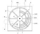
- the heat radiation fins F have an arc shape centered on the axis O, and are arranged at intervals in the radial direction and the circumferential direction. That is, the heat radiation fin F is divided into a plurality of parts in the circumferential direction. In other words, each heat radiation fin F has a plurality of fin pieces f arranged in the circumferential direction. Like the rib R, the fin piece f projects from the bottom surface 42A toward the other side (upper side) in the axis O direction. The protruding height of the fin piece f (that is, the dimension in the axis O direction) is larger than the protruding height of the rib R.
- the heat radiation fin F located on the outermost side in the radial direction is the outer peripheral heat radiation fin F1.
- the heat radiation fin F located on the innermost side in the radial direction is referred to as an inner peripheral heat radiation fin F3.
- the heat radiation fins F arranged between the outer peripheral heat radiation fins F1 and the inner peripheral heat radiation fins F3 are referred to as intermediate heat radiation fins F2.
- the number of divisions of the heat radiation fins F increases toward the inner circumference heat radiation fins F3 from the outer peripheral heat radiation fins F1. Further, the dimension of the fin piece f in the circumferential direction becomes larger toward the outer peripheral heat radiation fin F1 from the inner peripheral heat radiation fin F3.
- the outer peripheral heat radiation fin F1 extends from the end of the suction port 9, which will be described later, over a region of about 180 ° about the axis O when viewed from the axis O direction.
- the intermediate heat radiation fin F2 and the inner peripheral heat radiation fin F3 extend from the circumferential position separated from the suction port 9 from the outer peripheral heat radiation fin F1 over a region of about 180 ° about the axis O.
- a part of these heat radiation fins F overlaps with the rib R in the circumferential direction. That is, a part of the fin pieces f is integrally molded with the rib R.
- the surface of the bottom portion 42 opposite to the bottom surface 42A is the back surface 42B.
- the cover 5 is attached to the back surface 42B.
- An electrical component E including an IPM (intelligent power module) and the like is arranged on the back surface 42B, and is covered from the outside by a cover 5.
- a suction port 9 for guiding the refrigerant into the housing 4 from the outside is attached to the housing main body 41.
- the suction port 9 communicates with the inside and outside of the housing body 41 and guides the refrigerant toward the bottom surface 42A described above. Further, as shown in FIG. 2, the suction port 9 extends in a direction including a circular tangential component formed by the bottom surface 42A when viewed from the axis O direction. Therefore, the refrigerant flows on the bottom surface 42A in the circumferential direction centered on the axis O. That is, the above-mentioned heat radiation fins F are arranged in the direction in which the refrigerant flows (arrow Df in FIG. 2).
- the flow velocity of the refrigerant on the outer peripheral side of the bottom surface 42A is higher than that on the inner peripheral side. That is, as described above, the larger the outer peripheral heat radiation fin F1, the larger the dimension of the fin piece f in the flow direction Df, so it can be said that the larger the region where the flow velocity of the refrigerant is, the larger the dimension of the fin piece f.
- the heat radiation fin F as described above when the heat radiation fin F as described above is provided, the following problems may occur depending on the shape and arrangement thereof. For example, when the bottom surface 42A of the housing 4 is deformed by the pressure on the suction side, a large stress is generated in the heat radiation fin F, which may be damaged. Further, when the housing 4 is manufactured by casting, there is also a problem that defects including cracks and cavities occur due to the thickening due to the formation of the heat radiation fins F.
- the heat radiation fins F are divided into a plurality of parts in the flow direction Df of the refrigerant.
- the boundary layer component of the flow along the surface of the heat radiation fin F is divided in the flow direction Df.
- the leading edge effect can be obtained a plurality of times for each heat radiation fin F. Therefore, the cooling effect of the bottom surface 42A (housing 4) by the refrigerant can be enhanced.
- the leading edge effect here refers to the phenomenon that the thermal efficiency is highest at the site where the heat medium first collides.
- the heat radiation fin F is not divided, a large stress is generated between the heat radiation fin F and the bottom surface 42A at the center of the heat radiation fin F due to the deformation of the bottom surface 42A, and the heat radiation fin F may be damaged. be.
- the heat radiating fin F is divided into a plurality of parts, the stress generated by each of the divided heat radiating fins F can be suppressed to a small value even when the bottom surface 42A is deformed. Thereby, the strength of the housing 4 can be improved.
- the cooling effect of the bottom surface 42A (housing 4) by the refrigerant can be further enhanced.
- the protruding height of the rib R from the bottom surface 42A is smaller than the protruding height of the heat radiation fin F. This makes it possible to reduce the possibility that the flow of the refrigerant at the tip of the heat radiation fin F is obstructed by the rib R.
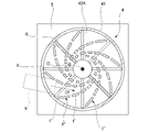
- each heat radiation fin F'extends inward in the radial direction from one side in the circumferential direction (that is, the side through which the refrigerant flows) toward the other side (the side through which the refrigerant flows away).
- a plurality (8) of such heat radiation fins F' are arranged at intervals in the circumferential direction. Further, each heat radiation fin F'is divided into a plurality of parts in the flow direction Df of the refrigerant.
- each radiating fin F' has a plurality of fin pieces f'arranged in the flow direction Df.
- the more the fin piece f'on the outer peripheral side where the flow velocity of the refrigerant is high the larger the dimension in the flow direction Df. Even with such a configuration, the same effect as that of the first embodiment can be obtained.
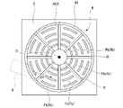
- the heat radiation fin Fb extends in the circumferential direction about the axis O and is divided into a plurality of parts in the circumferential direction. That is, the heat radiation fin Fb has a plurality of (eight) fin pieces fb arranged in the circumferential direction. A plurality of rows (4 rows) of such heat radiation fins Fb are provided at intervals in the radial direction. The larger the divided heat radiation fins Fb located on the outer side in the radial direction, the larger the dimension in the flow direction Df. Further, each fin piece fb is provided between a pair of ribs R adjacent to each other in the circumferential direction. In other words, each fin piece fb and the rib R do not overlap in the circumferential direction. More specifically, a space is formed in the circumferential direction between the fin piece fb and the rib R.
- the heat radiation fins Fb are provided between the ribs R.
- the heat radiation fin Fb and the rib R do not overlap in the circumferential direction.
- the flow of the refrigerant is disturbed when passing through the rib R, and the refrigerant collides with the heat radiation fin Fb in an accelerated state.
- the cooling effect of the heat radiation fins Fb can be further enhanced.
- the rib R and the heat radiation fin Fb are independent, a thick portion is not generated. This also reduces the possibility of defects occurring when the housing 4 is formed by casting.
- the ribs R' are formed at different circumferential positions with respect to the heat radiation fins Fb similar to those in the second embodiment. Specifically, each rib R'is formed so as to overlap the heat radiation fin Fb in the circumferential direction. That is, the four fin pieces fb and one rib R'are integrally formed.
- the heat radiation fin Fb and the rib R'overlap in the circumferential direction since the heat radiation fin Fb and the rib R'overlap in the circumferential direction, the apparent volume of the heat radiation fin Fb becomes large. As a result, the cooling effect of the heat radiation fins Fb can be further enhanced. In addition, since the stress generated in the heat radiation fin Fb when the bottom surface 42A is deformed can be dispersed to the rib R', the possibility that the heat radiation fin Fb is damaged can be further reduced.
- the scroll compressor 100 includes a shaft 1 that can rotate around the axis O, a motor 2 that rotationally drives the shaft 1, and a compressor body 3 that is driven by the rotation of the shaft 1.
- a housing 4 having a bottom surface 42A that covers the motor 2 and the compressor main body 3 and faces the motor 2 from the axis O direction, a suction port 9 that guides the refrigerant into the housing 4, and the bottom surface. It is formed in 42A, extends in the flow direction Df of the refrigerant, and includes heat radiation fins F, F', Fb divided into a plurality of parts in the flow direction Df.
- the heat radiation fins F are formed on the bottom surface 42A, and the heat radiation fins F, F', and Fb are divided into a plurality of parts in the flow direction Df of the refrigerant.
- the boundary layer component of the flow along the surface of the heat radiation fin F is divided in the flow direction Df.
- the leading edge effect can be obtained a plurality of times for each of the heat radiation fins F, F', and Fb. Therefore, the cooling effect of the bottom surface 42A (housing 4) by the refrigerant can be enhanced.
- the leading edge effect here refers to the phenomenon that the thermal efficiency is highest at the site where the heat medium first collides.
- the heat radiating fins F, F', Fb are not divided, a large stress is generated between the heat radiating fins F, F', Fb and the bottom surface 42A at the center of the heat radiating fins F, F', Fb due to the deformation of the bottom surface 42A.
- the heat radiation fins F, F', and Fb may be damaged.
- the higher the flow velocity region the larger the dimension of the divided heat radiation fins F, F', Fb (fin pieces f, f', fb) in the flow direction Df.
- This makes it possible to generate an appropriate number of leading edge effects according to the flow velocity distribution.
- the cooling effect of the bottom surface 42A (housing 4) by the refrigerant can be further enhanced.
- the heat radiation fins F and Fb extend in an arc shape centered on the axis O, and a plurality of the heat radiation fins F and Fb are provided at intervals in the radial direction and are provided outside in the radial direction.
- the leading edge effect can be generated more efficiently in accordance with the flow direction Df.
- the heat radiation fins F' extend radially inward from one side in the circumferential direction toward the other side with the axis O as the center, and are spaced in the circumferential direction. The more the divided radiating fins F'are located on the outer side in the radial direction, the larger the dimension in the flow direction Df.
- the scroll compressor 100 further includes a plurality of ribs R, R'protruding from the bottom surface 42A and extending radially around the axis O, and the ribs R, R'.
- the protruding height of the heat radiation fins F, F', Fb is smaller than the protruding height of the heat radiation fins F, F', Fb.
- the protruding height of the ribs R, R'from the bottom surface 42A is smaller than the protruding height of the heat radiation fins F, F', Fb. This makes it possible to reduce the possibility that the flow of the refrigerant at the tips of the heat radiation fins F, F', Fb is obstructed by the ribs R, R'.
- the heat radiation fins Fb are provided between the pair of ribs R adjacent to each other in the circumferential direction.
- the heat radiation fins Fb are provided between the ribs R.
- the heat radiation fin Fb and the rib R do not overlap in the circumferential direction.
- the flow of the refrigerant is disturbed when passing through the rib R, and the refrigerant collides with the heat radiation fin Fb in an accelerated state.
- the cooling effect of the heat radiation fins Fb can be further enhanced.
- the rib R and the heat radiation fin Fb are independent, a thick portion is not generated. This also reduces the possibility of defects occurring when the housing 4 is formed by casting.
- the heat radiation fin Fb is provided so as to overlap the rib R'in the circumferential direction.
- the heat radiation fin Fb and the rib R'overlap in the circumferential direction since the heat radiation fin Fb and the rib R'overlap in the circumferential direction, the apparent volume of the heat radiation fin Fb becomes large. As a result, the cooling effect of the heat radiation fins Fb can be further enhanced. In addition, since the stress generated in the heat radiation fin Fb when the bottom surface 42A is deformed can be dispersed to the rib R', the possibility that the heat radiation fin Fb is damaged can be further reduced.
- This disclosure relates to a scroll compressor. According to the present disclosure, it is possible to provide a scroll compressor having improved cooling performance and strength.
Landscapes
- Engineering & Computer Science (AREA)
- Mechanical Engineering (AREA)
- General Engineering & Computer Science (AREA)
- Applications Or Details Of Rotary Compressors (AREA)
- Rotary Pumps (AREA)
Abstract
このスクロール圧縮機は、軸線回りに回転可能なシャフトと、シャフトを回転駆動するモータと、シャフトの回転によって駆動される圧縮機本体と、モータ、及び圧縮機本体を覆うとともに、軸線方向からモータに対向する底面を有するハウジングと、ハウジング内に冷媒を導く吸入ポートと、底面に形成され、冷媒の流れ方向に延びるとともに、流れ方向に複数に分割された放熱フィンと、を備える。
Description
本開示は、スクロール圧縮機に関する。本願は、2020年10月16日、日本に出願された特願2020-174866に基づき優先権を主張し、その内容をここに援用する。
例えば車両用空調装置に用いられる圧縮機として、スクロール圧縮機が知られている(下記特許文献1参照)。スクロール圧縮機は、モータと、モータによって駆動される圧縮機本体と、これらモータ、及び圧縮機本体を収容するハウジングと、を備えている。
近年では、装置の小型化のために、スクロール圧縮機を駆動するためのインバータ回路としてインテリジェントパワーモジュール(IPM)を用いる例が増えている。この場合、従来のインバータ回路と比較して発熱密度が高まるため、冷却性能の向上が必要となる。特許文献1に記載された装置では、ハウジングにおけるインバータの背面側(裏面側)に、複数の放熱フィンを設けることで、冷却性能の向上が図れるとされている。
しかしながら、上記のような放熱フィンを設ける場合、その形状と配置によっては、以下のような課題が生じる虞がある。例えば、圧力によってハウジングの底面が変形した場合、放熱フィンに大きな応力が生じ、破損する可能性がある。また、ハウジングを鋳造によって製造する際に、放熱フィンを形成したことによる厚肉化が原因となって、割れや巣が生じるという課題もある。
本開示は上記課題を解決するためになされたものであって、冷却性能と強度が向上したスクロール圧縮機を提供することを目的とする。
上記課題を解決するために、本開示に係るスクロール圧縮機は、軸線回りに回転可能なシャフトと、前記シャフトを回転駆動するモータと、前記シャフトの回転によって駆動される圧縮機本体と、前記モータ、及び前記圧縮機本体を覆うとともに、前記軸線方向から前記モータに対向する底面を有するハウジングと、前記ハウジング内に冷媒を導く吸入ポートと、前記底面に形成され、前記冷媒の流れ方向に延びるとともに、該流れ方向に複数に分割された放熱フィンと、を備える。
本開示によれば、冷却性能と強度が向上したスクロール圧縮機を提供することができる。
(スクロール圧縮機の構成)
以下、本開示の実施形態に係るスクロール圧縮機100について、図1と図2を参照して説明する。スクロール圧縮機100は、例えば車両用の空調装置の冷媒を圧縮するために用いられる。図1に示すように、スクロール圧縮機100は、シャフト1と、モータ2と、圧縮機本体3と、ハウジング4と、カバー5と、上部軸受6と、下部軸受7と、ドライブブッシュ8と、吸入ポート9と、を備えている。
以下、本開示の実施形態に係るスクロール圧縮機100について、図1と図2を参照して説明する。スクロール圧縮機100は、例えば車両用の空調装置の冷媒を圧縮するために用いられる。図1に示すように、スクロール圧縮機100は、シャフト1と、モータ2と、圧縮機本体3と、ハウジング4と、カバー5と、上部軸受6と、下部軸受7と、ドライブブッシュ8と、吸入ポート9と、を備えている。
(シャフトの構成)
シャフト1は、軸線Oに沿って延びるとともに、当該軸線O回りに回転可能とされている。シャフト1は、シャフト本体10と、小径部11と、大径部12と、偏芯軸部13と、を有している。シャフト本体10は、軸線Oを中心とする円柱状をなしている。シャフト本体10は、軸線O方向の全域にわたって一様な径寸法を有している。シャフト本体10の外周面には、モータ2のロータ21(後述)が取り付けられている。
シャフト1は、軸線Oに沿って延びるとともに、当該軸線O回りに回転可能とされている。シャフト1は、シャフト本体10と、小径部11と、大径部12と、偏芯軸部13と、を有している。シャフト本体10は、軸線Oを中心とする円柱状をなしている。シャフト本体10は、軸線O方向の全域にわたって一様な径寸法を有している。シャフト本体10の外周面には、モータ2のロータ21(後述)が取り付けられている。
軸線O方向におけるシャフト本体10の一方側(下側)には、小径部11が設けられている。小径部11は、軸線Oを中心とする円柱状をなすとともに、シャフト本体10よりも小さな径寸法を有している。小径部11は、ハウジング4に取り付けられた下部軸受7によって軸線O方向一方側(下側)から支持されている。
シャフト本体10の軸線O方向他方側(上側)には、大径部12が設けられている。大径部12は、軸線Oを中心とする円柱状をなすとともに、シャフト本体10よりも大きな径寸法を有している。大径部12は、ハウジング4に固定された上部軸受6によって径方向から支持されている。
大径部12のさらに上側(軸線O方向他方側)には、偏芯軸部13が設けられている。偏芯軸部13は、大径部12から軸線O方向他方側に向かって突出している。偏芯軸部13は、軸線Oと平行をなすとともに、当該軸線Oから径方向にずれた位置に延びる偏芯軸Aを中心とする円柱状をなしている。したがって、シャフト1が回転するとき、偏芯軸部13は軸線O回りに公転(旋回)する。
(モータの構成)
モータ2は、シャフト1に回転駆動力を与える。モータ2は、ロータ21と、ステータ22と、を有している。ロータ21は、シャフト本体10に固定されている。ロータ21は、軸線Oを中心とする円筒状をなしている。詳しくは図示しないが、ロータ21は、複数の磁石を有している。ステータ22は、このロータ21を外周側から覆っている。ステータ22は、複数の鋼板を軸線O方向に積層して形成され、その周囲に銅線が巻回されることで複数のコイルが形成されている。
モータ2は、シャフト1に回転駆動力を与える。モータ2は、ロータ21と、ステータ22と、を有している。ロータ21は、シャフト本体10に固定されている。ロータ21は、軸線Oを中心とする円筒状をなしている。詳しくは図示しないが、ロータ21は、複数の磁石を有している。ステータ22は、このロータ21を外周側から覆っている。ステータ22は、複数の鋼板を軸線O方向に積層して形成され、その周囲に銅線が巻回されることで複数のコイルが形成されている。
ステータ22に通電することで、ステータ22とロータ21との間に電磁力が発生し、ロータ21に軸線O回りの回転力が与えられる。これにより、シャフト1が軸線O回りに回転する。
(圧縮機本体の構成)
圧縮機本体3は、モータ2によるシャフト1の回転によって駆動する。圧縮機本体3は、固定スクロール31と、可動スクロール32と、を有している。固定スクロール31は、軸線Oを中心とする円盤状の第一端板31Aと、この第一端板31Aの軸線O方向一方側(下側)に設けられた第一渦巻板31Bと、を有している。第一渦巻板31Bは、軸線Oを中心として渦巻状に延びている。固定スクロール31は、ハウジング4に固定されている。
圧縮機本体3は、モータ2によるシャフト1の回転によって駆動する。圧縮機本体3は、固定スクロール31と、可動スクロール32と、を有している。固定スクロール31は、軸線Oを中心とする円盤状の第一端板31Aと、この第一端板31Aの軸線O方向一方側(下側)に設けられた第一渦巻板31Bと、を有している。第一渦巻板31Bは、軸線Oを中心として渦巻状に延びている。固定スクロール31は、ハウジング4に固定されている。
可動スクロール32は、円盤状の第二端板32Aと、この第二端板32Aの軸線O方向他方側(上側)に設けられた第二渦巻板32Bと、ボス部32Cと、を有している。第二渦巻板32Bは、軸線Oを中心として渦巻状に延びている。第二渦巻板32Bの軸線O方向の寸法は、上述した第一渦巻板31Bの軸線O方向の寸法と同等である。このように第一渦巻板31Bと第二渦巻板32Bとが軸線O方向から噛み合うことで、両者の間に圧縮室が形成されている。
ボス部32Cは、第二端板32Aから軸線O方向一方側(下側)に向かって突出する円筒状の部分である。ボス部32Cは、ドライブブッシュ8を介してシャフト1の偏芯軸部13に取り付けられている。偏芯軸部13が軸線O回りに旋回することで、ドライブブッシュ8を通じて旋回力が可動スクロール32に伝達される。これにより、可動スクロール32は軸線O回りに旋回する。なお、詳しくは図示しないが、可動スクロール32自身の回転(自転)は、オルダムリングによって規制されている。
可動スクロール32が旋回することによって、上述の圧縮室の容積が時間変化し、当該圧縮室内を径方向外側から内側に送られる中途で冷媒が圧縮され、その圧力が上がる。高圧状態となった冷媒は、固定スクロール31の第一端板31Aに形成された開口部Hを通じてハウジング4内に導かれる。
(ハウジング・カバーの構成)
ハウジング4は、シャフト1、モータ2、及び圧縮機本体3を収容する有底円筒状の容器である。具体的には、ハウジング4は、軸線Oを中心とする円筒状のハウジング本体41と、ハウジング本体41の軸線O方向一方側の開口を塞ぐ底部42と、軸線O方向他方側の開口を塞ぐ蓋部43と、カバー5と、を有している。
ハウジング4は、シャフト1、モータ2、及び圧縮機本体3を収容する有底円筒状の容器である。具体的には、ハウジング4は、軸線Oを中心とする円筒状のハウジング本体41と、ハウジング本体41の軸線O方向一方側の開口を塞ぐ底部42と、軸線O方向他方側の開口を塞ぐ蓋部43と、カバー5と、を有している。
(リブ・放熱フィンの構成)
底部42の厚さ方向両面のうち、軸線O方向他方側(つまり、モータ2側)を向く面は底面42Aとされている。図2に示すように、底面42A上には、複数のリブRと、複数の放熱フィンFが形成されている。
底部42の厚さ方向両面のうち、軸線O方向他方側(つまり、モータ2側)を向く面は底面42Aとされている。図2に示すように、底面42A上には、複数のリブRと、複数の放熱フィンFが形成されている。
リブRは、底面42Aから軸線O方向他方側(上側)に向かって突出している。リブRは、軸線Oを中心として放射状に延びている。リブRは、一例として8つ設けられている。リブRは、吸入側の圧力によるハウジング4の変形を抑制するために設けられている。
放熱フィンFは、軸線Oを中心とする円弧状をなすとともに、径方向、及び周方向に間隔をあけて配列されている。つまり、放熱フィンFは周方向に複数に分割されている。言い換えると、各放熱フィンFは、周方向に配列された複数のフィン片fを有している。フィン片fはリブRと同様に底面42Aから軸線O方向他方側(上側)に向かって突出している。フィン片fの突出高さ(つまり、軸線O方向における寸法)は、リブRの突出高さよりも大きい。
径方向の最も外側に位置する放熱フィンFは、外周放熱フィンF1とされている。径方向の最も内側に位置する放熱フィンFは、内周放熱フィンF3とされている。これら外周放熱フィンF1と内周放熱フィンF3の中間に配置されている放熱フィンFは中間放熱フィンF2とされている。
本実施形態では、外周放熱フィンF1から内周放熱フィンF3に向かうに従って、放熱フィンFの分割数(フィン片fの数)が増加している。さらに、内周放熱フィンF3から外周放熱フィンF1に向かうほど、フィン片fの周方向における寸法が大きくなっている。
外周放熱フィンF1は、軸線O方向から見て、後述する吸入ポート9の端部から、軸線Oを中心として180°程度の領域にわたって延びている。一方で、中間放熱フィンF2及び内周放熱フィンF3は、外周放熱フィンF1よりも吸入ポート9から離間した周方向位置から、軸線Oを中心として180°程度の領域にわたって延びている。これら放熱フィンFのうちの一部は、リブRと周方向に重複している。つまり、一部のフィン片fはリブRと一体に成形されている。
再び図1に示すように、底部42における底面42Aと反対側の面(つまり、外側を向く面)は裏面42Bとされている。カバー5は裏面42Bに取り付けられている。裏面42Bには、IPM(インテリジェントパワーモジュール)等を含む電装品Eが配置され、カバー5によって外側から覆われている。
(吸入ポートの構成)
ハウジング本体41には、外部からハウジング4内に冷媒を導くための吸入ポート9が取り付けられている。吸入ポート9は、ハウジング本体41の内外を連通するとともに、上述した底面42Aに向かって冷媒を導く。さらに、図2に示すように、吸入ポート9は、軸線O方向から見て、底面42Aが形成する円形の接線方向成分を含む方向に延びている。したがって、底面42A上で冷媒は軸線Oを中心とする周方向に流れる。つまり、上述した放熱フィンFは、この冷媒の流れる方向(図2中の矢印Df)に配列されている。また、底面42Aの外周側では内周側に比べて冷媒の流速が高い。つまり、上述のように外周放熱フィンF1になるほどフィン片fの流れ方向Dfにおける寸法が大きいことから、冷媒の流速が高い領域になるほどフィン片fの寸法が大きくなると言える。
ハウジング本体41には、外部からハウジング4内に冷媒を導くための吸入ポート9が取り付けられている。吸入ポート9は、ハウジング本体41の内外を連通するとともに、上述した底面42Aに向かって冷媒を導く。さらに、図2に示すように、吸入ポート9は、軸線O方向から見て、底面42Aが形成する円形の接線方向成分を含む方向に延びている。したがって、底面42A上で冷媒は軸線Oを中心とする周方向に流れる。つまり、上述した放熱フィンFは、この冷媒の流れる方向(図2中の矢印Df)に配列されている。また、底面42Aの外周側では内周側に比べて冷媒の流速が高い。つまり、上述のように外周放熱フィンF1になるほどフィン片fの流れ方向Dfにおける寸法が大きいことから、冷媒の流速が高い領域になるほどフィン片fの寸法が大きくなると言える。
(作用効果)
ここで、上記のような放熱フィンFを設ける場合、その形状と配置によっては、以下のような課題が生じる虞がある。例えば、吸入側の圧力によってハウジング4の底面42Aが変形した場合、放熱フィンFに大きな応力が生じ、破損する可能性がある。また、ハウジング4を鋳造によって製造する際に、放熱フィンFを形成したことによる厚肉化が原因となって、割れや巣を含む不良が生じるという課題もある。
一方で、本実施形態では、放熱フィンFは冷媒の流れ方向Dfに複数に分割されている。これにより、放熱フィンFの表面に沿う流れの境界層成分が流れ方向Dfに分断される。その結果、1つの放熱フィンFごとに、複数回の前縁効果を得ることができる。したがって、冷媒による底面42A(ハウジング4)の冷却効果を高めることができる。(なお、ここで言う前縁効果とは、熱媒体が最初に衝突する部位で最も熱効率が高くなるという現象を指す。)
さらに、放熱フィンFが分割されていない場合には、底面42Aの変形に伴って、当該放熱フィンFの中央部で底面42Aとの間に大きな応力が発生し、放熱フィンFが破損する虞がある。しかしながら、上記構成によれば、放熱フィンFが複数に分割されているため、底面42Aに変形が生じた場合であっても、分割された放熱フィンFごとに生じる応力を小さく抑えることができる。これにより、ハウジング4の強度を向上させることができる。
さらに、放熱フィンFが分割されていない場合には、底面42Aの変形に伴って、当該放熱フィンFの中央部で底面42Aとの間に大きな応力が発生し、放熱フィンFが破損する虞がある。しかしながら、上記構成によれば、放熱フィンFが複数に分割されているため、底面42Aに変形が生じた場合であっても、分割された放熱フィンFごとに生じる応力を小さく抑えることができる。これにより、ハウジング4の強度を向上させることができる。
さらに、上記構成によれば、流速が高い外周側の領域になるほど、分割された放熱フィンF(フィン片f)の流れ方向Dfにおける寸法が大きい。これにより、流速分布に合わせて適正な回数の前縁効果を生じさせることができる。その結果、冷媒による底面42A(ハウジング4)の冷却効果をさらに高めることができる。
加えて、上記構成によれば、複数のリブRが設けられていることから、底面42A(ハウジング4)に吸入側の圧力による応力が生じた場合であっても、当該応力に十分に抗することができる。さらに、リブRの底面42Aからの突出高さは放熱フィンFの突出高さよりも小さい。これにより、放熱フィンFの先端における冷媒の流れがリブRによって阻害されてしまう可能性を低減することができる。
以上、本開示の第一実施形態について説明した。なお、本開示の要旨を逸脱しない限りにおいて、上記の構成に種々の変更や改修を施すことが可能である。
例えば図3に示すように、吸入ポート9による冷媒の流れ方向Df(つまり、放熱フィンF´の延びる方向)を変更することも可能である。具体的には、各放熱フィンF´は、周方向一方側(つまり、冷媒が流れてくる側)から他方側(冷媒が流れ去る側)に向かうに従って径方向内側に向かって延びている。このような放熱フィンF´が周方向に間隔をあけて複数(8つ)配列されている。また、各放熱フィンF´は、冷媒の流れ方向Dfに複数に分割されている。言い換えると、各放熱フィンF´は、流れ方向Dfに配列された複数のフィン片f´を有している。複数のフィン片f´のうち、冷媒の流速が高い外周側のフィン片f´になるほど、流れ方向Dfにおける寸法が大きい。このような構成によっても、上記第一実施形態と同様の作用効果を得ることができる。
<第二実施形態>
続いて、本開示の第二実施形態について、図4を参照して説明する。なお、上記第一実施形態と同様の構成については同一の符号を付し、詳細な説明を省略する。
続いて、本開示の第二実施形態について、図4を参照して説明する。なお、上記第一実施形態と同様の構成については同一の符号を付し、詳細な説明を省略する。
同図に示すように、本実施形態では、放熱フィンFbは、軸線Oを中心とする周方向に延びるとともに、当該周方向に複数に分割されている。つまり、放熱フィンFbは、周方向に配列された複数(8つ)のフィン片fbを有する。このような放熱フィンFbが径方向に間隔をあけて複数列(4列)設けられている。径方向外側に位置する分割された放熱フィンFbになるほど流れ方向Dfにおける寸法が大きい。さらに、各フィン片fbは、周方向に隣接する一対のリブR同士の間に設けられている。言い換えると、各フィン片fbとリブRとは、周方向に重複していない。さらに詳細には、フィン片fbとリブRとの間には周方向に間隔が形成されている。
上記構成によれば、放熱フィンFbがリブR同士の間に設けられている。言い換えると放熱フィンFbとリブRとが周方向に重複していない。これにより、リブRを通過する際に冷媒の流れに乱れが生じ、かつ加速した状態で放熱フィンFbに冷媒が衝突する。その結果、放熱フィンFbによる冷却効果をさらに高めることができる。さらに、リブRと放熱フィンFbとが独立していることから厚肉部位が生じない。これにより、鋳造によるハウジング4の形成時に不良が発生する可能性を低減することもできる。
以上、本開示の第二実施形態について説明した。なお、本開示の要旨を逸脱しない限りにおいて、上記の構成に種々の変更や改修を施すことが可能である。
<第三実施形態>
次に、本開示の第三実施形態について、図5を参照して説明する。なお、上述の各実施形態と同様の構成については同一の符号を付し、詳細な説明を省略する。
次に、本開示の第三実施形態について、図5を参照して説明する。なお、上述の各実施形態と同様の構成については同一の符号を付し、詳細な説明を省略する。
同図に示すように、本実施形態では、第二実施形態と同様の放熱フィンFbに対して、リブR´が異なる周方向位置に形成されている。具体的には、各リブR´は、放熱フィンFbと周方向に重複するように形成されている。つまり、4つのフィン片fbと1つのリブR´とが一体に形成されている。
上記構成によれば、放熱フィンFbとリブR´とが周方向に重複していることから、放熱フィンFbとしての見かけの体積が大きくなる。これにより、放熱フィンFbによる冷却効果をさらに高めることができる。加えて、底面42Aの変形時に、放熱フィンFbに生じる応力をリブR´にも分散させることができるため、放熱フィンFbが破損する可能性をさらに小さくすることもできる。
以上、本開示の第三実施形態について説明した。なお、本開示の要旨を逸脱しない限りにおいて、上記の構成に種々の変更や改修を施すことが可能である。
例えば、上記の第二実施形態と第三実施形態とを、底面42Aにおける領域ごとに組み合わせて適用することも可能である。
<付記>
各実施形態に記載のスクロール圧縮機100は、例えば以下のように把握される。
各実施形態に記載のスクロール圧縮機100は、例えば以下のように把握される。
(1)第1の態様に係るスクロール圧縮機100は、軸線O回りに回転可能なシャフト1と、前記シャフト1を回転駆動するモータ2と、前記シャフト1の回転によって駆動される圧縮機本体3と、前記モータ2、及び前記圧縮機本体3を覆うとともに、前記軸線O方向から前記モータ2に対向する底面42Aを有するハウジング4と、前記ハウジング4内に冷媒を導く吸入ポート9と、前記底面42Aに形成され、前記冷媒の流れ方向Dfに延びるとともに、該流れ方向Dfに複数に分割された放熱フィンF,F´,Fbと、を備える。
上記構成によれば、底面42A上に放熱フィンFが形成され、当該放熱フィンF,F´,Fbは冷媒の流れ方向Dfに複数に分割されている。これにより、放熱フィンFの表面に沿う流れの境界層成分が流れ方向Dfに分断される。その結果、1つの放熱フィンF,F´,Fbごとに、複数回の前縁効果を得ることができる。したがって、冷媒による底面42A(ハウジング4)の冷却効果を高めることができる。(なお、ここで言う前縁効果とは、熱媒体が最初に衝突する部位で最も熱効率が高くなるという現象を指す。)
さらに、放熱フィンF,F´,Fbが分割されていない場合には、底面42Aの変形に伴って、当該放熱フィンF,F´,Fbの中央部で底面42Aとの間に大きな応力が発生し、放熱フィンF,F´,Fbが破損する虞がある。しかしながら、上記構成によれば、放熱フィンF,F´,Fbが複数に分割されているため、底面42Aに変形が生じた場合であっても、分割された放熱フィンF,F´,Fbごとに生じる応力を小さく抑えることができる。これにより、ハウジング4の強度を向上させることができる。
さらに、放熱フィンF,F´,Fbが分割されていない場合には、底面42Aの変形に伴って、当該放熱フィンF,F´,Fbの中央部で底面42Aとの間に大きな応力が発生し、放熱フィンF,F´,Fbが破損する虞がある。しかしながら、上記構成によれば、放熱フィンF,F´,Fbが複数に分割されているため、底面42Aに変形が生じた場合であっても、分割された放熱フィンF,F´,Fbごとに生じる応力を小さく抑えることができる。これにより、ハウジング4の強度を向上させることができる。
(2)第2の態様に係るスクロール圧縮機100では、前記冷媒の流速が高い領域に位置する前記分割された放熱フィンF,F´,Fbになるほど前記流れ方向Dfにおける寸法が大きい。
上記構成によれば、流速が高い領域になるほど、分割された放熱フィンF,F´,Fb(フィン片f,f´,fb)の流れ方向Dfにおける寸法が大きい。これにより、流速分布に合わせて適正な回数の前縁効果を生じさせることができる。その結果、冷媒による底面42A(ハウジング4)の冷却効果をさらに高めることができる。
(3)第3の態様に係るスクロール圧縮機100では、前記放熱フィンF,Fbは、前記軸線Oを中心とする円弧状に延びるとともに、径方向に間隔をあけて複数設けられ、径方向外側に位置する前記分割された放熱フィンF,Fbになるほど前記流れ方向Dfにおける寸法が大きい。
上記構成によれば、冷媒の流れ方向Dfが軸線Oに対する周方向である場合に、当該流れ方向Dfに合わせてより効率的に前縁効果を生じさせることができる。
(4)第4の態様に係るスクロール圧縮機100では、前記放熱フィンF´は、前記軸線Oを中心として周方向の一方側から他方側に向かうに従って径方向内側に延びるとともに、周方向に間隔をあけて複数設けられ、径方向外側に位置する前記分割された放熱フィンF´になるほど前記流れ方向Dfにおける寸法が大きい。
上記構成によれば、冷媒の流れ方向Dfが、周方向一方側から他方側に向かうに従って径方向内側に向かう方向である場合に、当該流れ方向Dfに合わせてより効率的に前縁効果を生じさせることができる。
(5)第5の態様に係るスクロール圧縮機100は、前記底面42Aから突出するとともに、前記軸線Oを中心とする放射状に延びる複数のリブR,R´をさらに備え、前記リブR,R´の突出高さは前記放熱フィンF,F´,Fbの突出高さよりも小さい。
上記構成によれば、複数のリブR,R´が設けられていることから、底面42A(ハウジング4)に吸入側の圧力による応力が生じた場合であっても、当該応力に十分に抗することができる。さらに、リブR,R´の底面42Aからの突出高さは放熱フィンF,F´,Fbの突出高さよりも小さい。これにより、放熱フィンF,F´,Fbの先端における冷媒の流れがリブR,R´によって阻害されてしまう可能性を低減することができる。
(6)第6の態様に係るスクロール圧縮機100では、前記放熱フィンFbは、周方向に隣接する一対の前記リブR同士の間に設けられている。
上記構成によれば、放熱フィンFbがリブR同士の間に設けられている。言い換えると放熱フィンFbとリブRとが周方向に重複していない。これにより、リブRを通過する際に冷媒の流れに乱れが生じ、かつ加速した状態で放熱フィンFbに冷媒が衝突する。その結果、放熱フィンFbによる冷却効果をさらに高めることができる。さらに、リブRと放熱フィンFbとが独立していることから厚肉部位が生じない。これにより、鋳造によるハウジング4の形成時に不良が発生する可能性を低減することもできる。
(7)第7の態様に係るスクロール圧縮機100では、前記放熱フィンFbは、前記リブR´と周方向に重複するように設けられている。
上記構成によれば、放熱フィンFbとリブR´とが周方向に重複していることから、放熱フィンFbとしての見かけの体積が大きくなる。これにより、放熱フィンFbによる冷却効果をさらに高めることができる。加えて、底面42Aの変形時に、放熱フィンFbに生じる応力をリブR´にも分散させることができるため、放熱フィンFbが破損する可能性をさらに小さくすることもできる。
本開示は、スクロール圧縮機に関する。本開示によれば、冷却性能と強度が向上したスクロール圧縮機を提供することができる。
100 スクロール圧縮機
1 シャフト
2 モータ
3 圧縮機本体
4 ハウジング
4S 内周面
5 カバー
6 上部軸受
7 下部軸受
8 ドライブブッシュ
9 吸入ポート
10 シャフト本体
11 小径部
12 大径部
13 偏芯軸部
21 ロータ
22 ステータ
31 固定スクロール
31A 第一端板
31B 第一渦巻板
32 可動スクロール
32A 第二端板
32B 第二渦巻板
32C ボス部
41 ハウジング本体
42 底部
42A 底面
42B 裏面
43 蓋部
A 偏芯軸
Df 流れ方向
f,f´,fb フィン片
F,F´,Fb 放熱フィン
F1 外周放熱フィン
F2 中間放熱フィン
F3 内周放熱フィン
H 開口部
O 軸線
P 吸入流路
R,R´ リブ
1 シャフト
2 モータ
3 圧縮機本体
4 ハウジング
4S 内周面
5 カバー
6 上部軸受
7 下部軸受
8 ドライブブッシュ
9 吸入ポート
10 シャフト本体
11 小径部
12 大径部
13 偏芯軸部
21 ロータ
22 ステータ
31 固定スクロール
31A 第一端板
31B 第一渦巻板
32 可動スクロール
32A 第二端板
32B 第二渦巻板
32C ボス部
41 ハウジング本体
42 底部
42A 底面
42B 裏面
43 蓋部
A 偏芯軸
Df 流れ方向
f,f´,fb フィン片
F,F´,Fb 放熱フィン
F1 外周放熱フィン
F2 中間放熱フィン
F3 内周放熱フィン
H 開口部
O 軸線
P 吸入流路
R,R´ リブ
Claims (7)
- 軸線回りに回転可能なシャフトと、
前記シャフトを回転駆動するモータと、
前記シャフトの回転によって駆動される圧縮機本体と、
前記モータ、及び前記圧縮機本体を覆うとともに、前記軸線方向から前記モータに対向する底面を有するハウジングと、
前記ハウジング内に冷媒を導く吸入ポートと、
前記底面に形成され、前記冷媒の流れ方向に延びるとともに、該流れ方向に複数に分割された放熱フィンと、
を備えるスクロール圧縮機。 - 前記冷媒の流速が高い領域に位置する前記分割された放熱フィンになるほど前記流れ方向における寸法が大きい請求項1に記載のスクロール圧縮機。
- 前記放熱フィンは、前記軸線を中心とする円弧状に延びるとともに、径方向に間隔をあけて複数設けられ、径方向外側に位置する前記分割された放熱フィンになるほど前記流れ方向における寸法が大きい請求項1又は2に記載のスクロール圧縮機。
- 前記放熱フィンは、前記軸線を中心として周方向の一方側から他方側に向かうに従って径方向内側に延びるとともに、周方向に間隔をあけて複数設けられ、径方向外側に位置する前記分割された放熱フィンになるほど前記流れ方向における寸法が大きい請求項1又は2に記載のスクロール圧縮機。
- 前記底面から突出するとともに、前記軸線を中心とする放射状に延びる複数のリブをさらに備え、前記リブの突出高さは前記放熱フィンの突出高さよりも小さい請求項1から4のいずれか一項に記載のスクロール圧縮機。
- 前記放熱フィンは、周方向に隣接する一対の前記リブ同士の間に設けられている請求項5に記載のスクロール圧縮機。
- 前記放熱フィンは、前記リブと周方向に重複するように設けられている請求項5に記載のスクロール圧縮機。
Priority Applications (3)
| Application Number | Priority Date | Filing Date | Title |
|---|---|---|---|
| CN202180063336.0A CN116194672B (zh) | 2020-10-16 | 2021-10-15 | 涡旋压缩机 |
| DE112021005451.1T DE112021005451T5 (de) | 2020-10-16 | 2021-10-15 | Scrollkompressor |
| US18/028,409 US12123415B2 (en) | 2020-10-16 | 2021-10-15 | Scroll compressor housing with fin arrangement |
Applications Claiming Priority (2)
| Application Number | Priority Date | Filing Date | Title |
|---|---|---|---|
| JP2020-174866 | 2020-10-16 | ||
| JP2020174866A JP7607432B2 (ja) | 2020-10-16 | 2020-10-16 | スクロール圧縮機 |
Publications (1)
| Publication Number | Publication Date |
|---|---|
| WO2022080488A1 true WO2022080488A1 (ja) | 2022-04-21 |
Family
ID=81208127
Family Applications (1)
| Application Number | Title | Priority Date | Filing Date |
|---|---|---|---|
| PCT/JP2021/038262 Ceased WO2022080488A1 (ja) | 2020-10-16 | 2021-10-15 | スクロール圧縮機 |
Country Status (5)
| Country | Link |
|---|---|
| US (1) | US12123415B2 (ja) |
| JP (1) | JP7607432B2 (ja) |
| CN (1) | CN116194672B (ja) |
| DE (1) | DE112021005451T5 (ja) |
| WO (1) | WO2022080488A1 (ja) |
Citations (4)
| Publication number | Priority date | Publication date | Assignee | Title |
|---|---|---|---|---|
| JPH11317482A (ja) * | 1997-12-25 | 1999-11-16 | Furukawa Electric Co Ltd:The | ヒートシンク |
| JP2006009776A (ja) * | 2004-05-28 | 2006-01-12 | Hitachi Ltd | スクロール式流体機械 |
| JP3976512B2 (ja) * | 2000-09-29 | 2007-09-19 | サンデン株式会社 | 冷媒圧縮用電動式圧縮機 |
| KR20110072323A (ko) * | 2009-12-22 | 2011-06-29 | 한라공조주식회사 | 전동식 압축기 |
Family Cites Families (10)
| Publication number | Priority date | Publication date | Assignee | Title |
|---|---|---|---|---|
| JPH07119672A (ja) * | 1993-10-20 | 1995-05-09 | Tokico Ltd | スクロール流体機械 |
| JPH08195456A (ja) | 1995-01-17 | 1996-07-30 | Toto Ltd | 電子機器冷却装置 |
| TW378267B (en) * | 1997-12-25 | 2000-01-01 | Furukawa Electric Co Ltd | Heat sink |
| JP2002033421A (ja) * | 2000-07-14 | 2002-01-31 | Shinozaki Seisakusho:Kk | 放熱器 |
| JP2006009778A (ja) | 2004-05-21 | 2006-01-12 | Bridgestone Corp | ポンプアップ装置及びシーリング剤注入装置 |
| JP2007224809A (ja) * | 2006-02-23 | 2007-09-06 | Matsushita Electric Ind Co Ltd | 電動圧縮機 |
| JP2012047140A (ja) | 2010-08-30 | 2012-03-08 | Panasonic Corp | 電動圧縮機 |
| JP6989240B2 (ja) | 2019-04-17 | 2022-01-05 | 株式会社大一商会 | 遊技機 |
| JP2022047260A (ja) * | 2020-09-11 | 2022-03-24 | 三菱重工業株式会社 | スクロール圧縮機 |
| JP2022065800A (ja) * | 2020-10-16 | 2022-04-28 | 三菱重工業株式会社 | スクロール圧縮機 |
-
2020
- 2020-10-16 JP JP2020174866A patent/JP7607432B2/ja active Active
-
2021
- 2021-10-15 WO PCT/JP2021/038262 patent/WO2022080488A1/ja not_active Ceased
- 2021-10-15 US US18/028,409 patent/US12123415B2/en active Active
- 2021-10-15 CN CN202180063336.0A patent/CN116194672B/zh active Active
- 2021-10-15 DE DE112021005451.1T patent/DE112021005451T5/de active Pending
Patent Citations (4)
| Publication number | Priority date | Publication date | Assignee | Title |
|---|---|---|---|---|
| JPH11317482A (ja) * | 1997-12-25 | 1999-11-16 | Furukawa Electric Co Ltd:The | ヒートシンク |
| JP3976512B2 (ja) * | 2000-09-29 | 2007-09-19 | サンデン株式会社 | 冷媒圧縮用電動式圧縮機 |
| JP2006009776A (ja) * | 2004-05-28 | 2006-01-12 | Hitachi Ltd | スクロール式流体機械 |
| KR20110072323A (ko) * | 2009-12-22 | 2011-06-29 | 한라공조주식회사 | 전동식 압축기 |
Also Published As
| Publication number | Publication date |
|---|---|
| US12123415B2 (en) | 2024-10-22 |
| CN116194672B (zh) | 2025-04-15 |
| DE112021005451T5 (de) | 2023-08-17 |
| US20230358234A1 (en) | 2023-11-09 |
| JP7607432B2 (ja) | 2024-12-27 |
| JP2022065998A (ja) | 2022-04-28 |
| CN116194672A (zh) | 2023-05-30 |
Similar Documents
| Publication | Publication Date | Title |
|---|---|---|
| JP5747632B2 (ja) | 遠心ファン | |
| US7598634B2 (en) | Fan motor | |
| JP6571293B2 (ja) | 回転子、回転電機、および圧縮機 | |
| CN1127193C (zh) | 带自冷风扇的电动机 | |
| JP6818869B2 (ja) | 電動機および送風装置 | |
| CN109578300B (zh) | 离心风扇 | |
| JP6674545B2 (ja) | モータ一体型流体機械 | |
| EP3576261B1 (en) | Motor and compressor that uses same | |
| JP2022065800A (ja) | スクロール圧縮機 | |
| WO2023136117A1 (ja) | 回転電機 | |
| JP6654414B2 (ja) | 電動圧縮機 | |
| JP2017219036A (ja) | 送風装置 | |
| JP2022065998A (ja) | スクロール圧縮機 | |
| US9581162B2 (en) | Compressor | |
| JP2009022146A (ja) | アキシャルモータ | |
| CN120062125A (zh) | 离心压缩机 | |
| JP2022065996A (ja) | スクロール圧縮機 | |
| JP2015224600A (ja) | 電動過給機 | |
| JP2022065862A (ja) | スクロール圧縮機 | |
| JP2022047260A (ja) | スクロール圧縮機 | |
| JP5517714B2 (ja) | 回転電機 | |
| JP2015137548A (ja) | 電動過給機 | |
| JP2006283602A (ja) | 圧縮機 | |
| CN116457584B (zh) | 旋转机械 | |
| JP5455676B2 (ja) | スクロール式流体機械 |
Legal Events
| Date | Code | Title | Description |
|---|---|---|---|
| 121 | Ep: the epo has been informed by wipo that ep was designated in this application |
Ref document number: 21880223 Country of ref document: EP Kind code of ref document: A1 |
|
| 122 | Ep: pct application non-entry in european phase |
Ref document number: 21880223 Country of ref document: EP Kind code of ref document: A1 |
|
| WWG | Wipo information: grant in national office |
Ref document number: 202180063336.0 Country of ref document: CN |