WO2022080483A1 - 摩擦攪拌点接合装置及びその運転方法 - Google Patents
摩擦攪拌点接合装置及びその運転方法 Download PDFInfo
- Publication number
- WO2022080483A1 WO2022080483A1 PCT/JP2021/038225 JP2021038225W WO2022080483A1 WO 2022080483 A1 WO2022080483 A1 WO 2022080483A1 JP 2021038225 W JP2021038225 W JP 2021038225W WO 2022080483 A1 WO2022080483 A1 WO 2022080483A1
- Authority
- WO
- WIPO (PCT)
- Prior art keywords
- shoulder
- friction stir
- tip
- pin
- controller
- Prior art date
- Legal status (The legal status is an assumption and is not a legal conclusion. Google has not performed a legal analysis and makes no representation as to the accuracy of the status listed.)
- Ceased
Links
Images







Classifications
-
- B—PERFORMING OPERATIONS; TRANSPORTING
- B23—MACHINE TOOLS; METAL-WORKING NOT OTHERWISE PROVIDED FOR
- B23K—SOLDERING OR UNSOLDERING; WELDING; CLADDING OR PLATING BY SOLDERING OR WELDING; CUTTING BY APPLYING HEAT LOCALLY, e.g. FLAME CUTTING; WORKING BY LASER BEAM
- B23K20/00—Non-electric welding by applying impact or other pressure, with or without the application of heat, e.g. cladding or plating
- B23K20/12—Non-electric welding by applying impact or other pressure, with or without the application of heat, e.g. cladding or plating the heat being generated by friction; Friction welding
- B23K20/122—Non-electric welding by applying impact or other pressure, with or without the application of heat, e.g. cladding or plating the heat being generated by friction; Friction welding using a non-consumable tool, e.g. friction stir welding
- B23K20/123—Controlling or monitoring the welding process
-
- B—PERFORMING OPERATIONS; TRANSPORTING
- B23—MACHINE TOOLS; METAL-WORKING NOT OTHERWISE PROVIDED FOR
- B23K—SOLDERING OR UNSOLDERING; WELDING; CLADDING OR PLATING BY SOLDERING OR WELDING; CUTTING BY APPLYING HEAT LOCALLY, e.g. FLAME CUTTING; WORKING BY LASER BEAM
- B23K20/00—Non-electric welding by applying impact or other pressure, with or without the application of heat, e.g. cladding or plating
- B23K20/12—Non-electric welding by applying impact or other pressure, with or without the application of heat, e.g. cladding or plating the heat being generated by friction; Friction welding
- B23K20/122—Non-electric welding by applying impact or other pressure, with or without the application of heat, e.g. cladding or plating the heat being generated by friction; Friction welding using a non-consumable tool, e.g. friction stir welding
- B23K20/1245—Non-electric welding by applying impact or other pressure, with or without the application of heat, e.g. cladding or plating the heat being generated by friction; Friction welding using a non-consumable tool, e.g. friction stir welding characterised by the apparatus
- B23K20/1255—Tools therefor, e.g. characterised by the shape of the probe
-
- B—PERFORMING OPERATIONS; TRANSPORTING
- B23—MACHINE TOOLS; METAL-WORKING NOT OTHERWISE PROVIDED FOR
- B23K—SOLDERING OR UNSOLDERING; WELDING; CLADDING OR PLATING BY SOLDERING OR WELDING; CUTTING BY APPLYING HEAT LOCALLY, e.g. FLAME CUTTING; WORKING BY LASER BEAM
- B23K20/00—Non-electric welding by applying impact or other pressure, with or without the application of heat, e.g. cladding or plating
- B23K20/12—Non-electric welding by applying impact or other pressure, with or without the application of heat, e.g. cladding or plating the heat being generated by friction; Friction welding
- B23K20/122—Non-electric welding by applying impact or other pressure, with or without the application of heat, e.g. cladding or plating the heat being generated by friction; Friction welding using a non-consumable tool, e.g. friction stir welding
- B23K20/1265—Non-butt welded joints, e.g. overlap-joints, T-joints or spot welds
-
- B—PERFORMING OPERATIONS; TRANSPORTING
- B23—MACHINE TOOLS; METAL-WORKING NOT OTHERWISE PROVIDED FOR
- B23K—SOLDERING OR UNSOLDERING; WELDING; CLADDING OR PLATING BY SOLDERING OR WELDING; CUTTING BY APPLYING HEAT LOCALLY, e.g. FLAME CUTTING; WORKING BY LASER BEAM
- B23K20/00—Non-electric welding by applying impact or other pressure, with or without the application of heat, e.g. cladding or plating
- B23K20/22—Non-electric welding by applying impact or other pressure, with or without the application of heat, e.g. cladding or plating taking account of the properties of the materials to be welded
- B23K20/227—Non-electric welding by applying impact or other pressure, with or without the application of heat, e.g. cladding or plating taking account of the properties of the materials to be welded with ferrous layer
-
- B—PERFORMING OPERATIONS; TRANSPORTING
- B23—MACHINE TOOLS; METAL-WORKING NOT OTHERWISE PROVIDED FOR
- B23K—SOLDERING OR UNSOLDERING; WELDING; CLADDING OR PLATING BY SOLDERING OR WELDING; CUTTING BY APPLYING HEAT LOCALLY, e.g. FLAME CUTTING; WORKING BY LASER BEAM
- B23K20/00—Non-electric welding by applying impact or other pressure, with or without the application of heat, e.g. cladding or plating
- B23K20/22—Non-electric welding by applying impact or other pressure, with or without the application of heat, e.g. cladding or plating taking account of the properties of the materials to be welded
- B23K20/227—Non-electric welding by applying impact or other pressure, with or without the application of heat, e.g. cladding or plating taking account of the properties of the materials to be welded with ferrous layer
- B23K20/2275—Non-electric welding by applying impact or other pressure, with or without the application of heat, e.g. cladding or plating taking account of the properties of the materials to be welded with ferrous layer the other layer being aluminium
-
- B—PERFORMING OPERATIONS; TRANSPORTING
- B23—MACHINE TOOLS; METAL-WORKING NOT OTHERWISE PROVIDED FOR
- B23K—SOLDERING OR UNSOLDERING; WELDING; CLADDING OR PLATING BY SOLDERING OR WELDING; CUTTING BY APPLYING HEAT LOCALLY, e.g. FLAME CUTTING; WORKING BY LASER BEAM
- B23K20/00—Non-electric welding by applying impact or other pressure, with or without the application of heat, e.g. cladding or plating
- B23K20/22—Non-electric welding by applying impact or other pressure, with or without the application of heat, e.g. cladding or plating taking account of the properties of the materials to be welded
- B23K20/233—Non-electric welding by applying impact or other pressure, with or without the application of heat, e.g. cladding or plating taking account of the properties of the materials to be welded without ferrous layer
-
- B—PERFORMING OPERATIONS; TRANSPORTING
- B23—MACHINE TOOLS; METAL-WORKING NOT OTHERWISE PROVIDED FOR
- B23K—SOLDERING OR UNSOLDERING; WELDING; CLADDING OR PLATING BY SOLDERING OR WELDING; CUTTING BY APPLYING HEAT LOCALLY, e.g. FLAME CUTTING; WORKING BY LASER BEAM
- B23K20/00—Non-electric welding by applying impact or other pressure, with or without the application of heat, e.g. cladding or plating
- B23K20/22—Non-electric welding by applying impact or other pressure, with or without the application of heat, e.g. cladding or plating taking account of the properties of the materials to be welded
- B23K20/233—Non-electric welding by applying impact or other pressure, with or without the application of heat, e.g. cladding or plating taking account of the properties of the materials to be welded without ferrous layer
- B23K20/2333—Non-electric welding by applying impact or other pressure, with or without the application of heat, e.g. cladding or plating taking account of the properties of the materials to be welded without ferrous layer one layer being aluminium, magnesium or beryllium
-
- B—PERFORMING OPERATIONS; TRANSPORTING
- B23—MACHINE TOOLS; METAL-WORKING NOT OTHERWISE PROVIDED FOR
- B23K—SOLDERING OR UNSOLDERING; WELDING; CLADDING OR PLATING BY SOLDERING OR WELDING; CUTTING BY APPLYING HEAT LOCALLY, e.g. FLAME CUTTING; WORKING BY LASER BEAM
- B23K20/00—Non-electric welding by applying impact or other pressure, with or without the application of heat, e.g. cladding or plating
- B23K20/12—Non-electric welding by applying impact or other pressure, with or without the application of heat, e.g. cladding or plating the heat being generated by friction; Friction welding
- B23K20/122—Non-electric welding by applying impact or other pressure, with or without the application of heat, e.g. cladding or plating the heat being generated by friction; Friction welding using a non-consumable tool, e.g. friction stir welding
- B23K20/1245—Non-electric welding by applying impact or other pressure, with or without the application of heat, e.g. cladding or plating the heat being generated by friction; Friction welding using a non-consumable tool, e.g. friction stir welding characterised by the apparatus
- B23K20/126—Workpiece support, i.e. backing or clamping
-
- B—PERFORMING OPERATIONS; TRANSPORTING
- B23—MACHINE TOOLS; METAL-WORKING NOT OTHERWISE PROVIDED FOR
- B23K—SOLDERING OR UNSOLDERING; WELDING; CLADDING OR PLATING BY SOLDERING OR WELDING; CUTTING BY APPLYING HEAT LOCALLY, e.g. FLAME CUTTING; WORKING BY LASER BEAM
- B23K2103/00—Materials to be soldered, welded or cut
- B23K2103/02—Iron or ferrous alloys
- B23K2103/04—Steel or steel alloys
-
- B—PERFORMING OPERATIONS; TRANSPORTING
- B23—MACHINE TOOLS; METAL-WORKING NOT OTHERWISE PROVIDED FOR
- B23K—SOLDERING OR UNSOLDERING; WELDING; CLADDING OR PLATING BY SOLDERING OR WELDING; CUTTING BY APPLYING HEAT LOCALLY, e.g. FLAME CUTTING; WORKING BY LASER BEAM
- B23K2103/00—Materials to be soldered, welded or cut
- B23K2103/02—Iron or ferrous alloys
- B23K2103/04—Steel or steel alloys
- B23K2103/05—Stainless steel
-
- B—PERFORMING OPERATIONS; TRANSPORTING
- B23—MACHINE TOOLS; METAL-WORKING NOT OTHERWISE PROVIDED FOR
- B23K—SOLDERING OR UNSOLDERING; WELDING; CLADDING OR PLATING BY SOLDERING OR WELDING; CUTTING BY APPLYING HEAT LOCALLY, e.g. FLAME CUTTING; WORKING BY LASER BEAM
- B23K2103/00—Materials to be soldered, welded or cut
- B23K2103/08—Non-ferrous metals or alloys
- B23K2103/10—Aluminium or alloys thereof
-
- B—PERFORMING OPERATIONS; TRANSPORTING
- B23—MACHINE TOOLS; METAL-WORKING NOT OTHERWISE PROVIDED FOR
- B23K—SOLDERING OR UNSOLDERING; WELDING; CLADDING OR PLATING BY SOLDERING OR WELDING; CUTTING BY APPLYING HEAT LOCALLY, e.g. FLAME CUTTING; WORKING BY LASER BEAM
- B23K2103/00—Materials to be soldered, welded or cut
- B23K2103/08—Non-ferrous metals or alloys
- B23K2103/12—Copper or alloys thereof
-
- B—PERFORMING OPERATIONS; TRANSPORTING
- B23—MACHINE TOOLS; METAL-WORKING NOT OTHERWISE PROVIDED FOR
- B23K—SOLDERING OR UNSOLDERING; WELDING; CLADDING OR PLATING BY SOLDERING OR WELDING; CUTTING BY APPLYING HEAT LOCALLY, e.g. FLAME CUTTING; WORKING BY LASER BEAM
- B23K2103/00—Materials to be soldered, welded or cut
- B23K2103/08—Non-ferrous metals or alloys
- B23K2103/14—Titanium or alloys thereof
-
- B—PERFORMING OPERATIONS; TRANSPORTING
- B23—MACHINE TOOLS; METAL-WORKING NOT OTHERWISE PROVIDED FOR
- B23K—SOLDERING OR UNSOLDERING; WELDING; CLADDING OR PLATING BY SOLDERING OR WELDING; CUTTING BY APPLYING HEAT LOCALLY, e.g. FLAME CUTTING; WORKING BY LASER BEAM
- B23K2103/00—Materials to be soldered, welded or cut
- B23K2103/08—Non-ferrous metals or alloys
- B23K2103/15—Magnesium or alloys thereof
-
- B—PERFORMING OPERATIONS; TRANSPORTING
- B23—MACHINE TOOLS; METAL-WORKING NOT OTHERWISE PROVIDED FOR
- B23K—SOLDERING OR UNSOLDERING; WELDING; CLADDING OR PLATING BY SOLDERING OR WELDING; CUTTING BY APPLYING HEAT LOCALLY, e.g. FLAME CUTTING; WORKING BY LASER BEAM
- B23K2103/00—Materials to be soldered, welded or cut
- B23K2103/18—Dissimilar materials
-
- B—PERFORMING OPERATIONS; TRANSPORTING
- B23—MACHINE TOOLS; METAL-WORKING NOT OTHERWISE PROVIDED FOR
- B23K—SOLDERING OR UNSOLDERING; WELDING; CLADDING OR PLATING BY SOLDERING OR WELDING; CUTTING BY APPLYING HEAT LOCALLY, e.g. FLAME CUTTING; WORKING BY LASER BEAM
- B23K2103/00—Materials to be soldered, welded or cut
- B23K2103/18—Dissimilar materials
- B23K2103/20—Ferrous alloys and aluminium or alloys thereof
-
- B—PERFORMING OPERATIONS; TRANSPORTING
- B23—MACHINE TOOLS; METAL-WORKING NOT OTHERWISE PROVIDED FOR
- B23K—SOLDERING OR UNSOLDERING; WELDING; CLADDING OR PLATING BY SOLDERING OR WELDING; CUTTING BY APPLYING HEAT LOCALLY, e.g. FLAME CUTTING; WORKING BY LASER BEAM
- B23K2103/00—Materials to be soldered, welded or cut
- B23K2103/30—Organic materials
- B23K2103/42—Plastics other than composite materials
Definitions
- This specification discloses a friction stir welding device and an operating method thereof.
- a dissimilar metal joining method is known for the purpose of making it possible to join the first metal material and the second metal material with high quality regardless of the variation in the thickness of each of the first and second metal materials. (See, for example, Patent Document 1).
- the intention of the present applicant is that the tip of the shoulder member or the tip of the pin member is the contact surface of the second member with the first member, as compared with the dissimilar metal joining method disclosed in Patent Document 1.
- the present invention provides a friction stir point joining device and an operation method thereof, which can more clearly determine that the corrosion point has been reached.
- a preferable friction stir welding device is a friction stir welding device having a first member and a second member and joining by softening the object to be joined by frictional heat, and the friction stir welding device.
- the friction stir welding device has a pin member formed in a columnar shape, a shoulder member formed in a cylindrical shape through which the pin member is inserted therein, and the pin member and the shoulder member of the pin member.
- the first member includes a rotary drive that rotates around an axis that coincides with the axis, an advance / retreat drive that moves the pin member and the shoulder member forward and backward along the axis, and a controller, respectively.
- the controller The rotation drive and the advance / retreat drive are operated so that the pin member and the shoulder member press the joined portion of the object to be joined in a rotated state.
- the rotation drive and the advance / retreat drive are operated so that the pin member and the shoulder member agitate the object to be joined.
- a predetermined first time elapsed in a state where the speed in the axial direction of the shoulder member in a rotated state or the pin member in a rotated state is a predetermined first speed set in advance. If so, it is determined that the tip of the shoulder member or the tip of the pin member has reached the contact surface of the second member with the first member.
- the operation method of the friction stir point joining device is a friction stir point joining device having a first member and a second member and joining by softening the object to be joined by friction heat, and the friction stir point joining device.
- the first member includes a rotary drive that rotates around an axis, an advance / retreat drive that moves the pin member and the shoulder member forward and backward along the axis, and a controller, and the first member is the pin. It is arranged so as to face the member and the shoulder member, and is made of a material having a lower melting point than the second member.
- the controller The rotation drive and the advance / retreat drive are operated so that the pin member and the shoulder member press the joined portion of the object to be joined in a rotated state.
- the rotation drive and the advance / retreat drive are operated so that the pin member and the shoulder member agitate the object to be joined.
- a predetermined first time elapsed in a state where the speed in the axial direction of the shoulder member in a rotated state or the pin member in a rotated state is a predetermined first speed set in advance. If so, it is determined that the tip of the shoulder member or the tip of the pin member has reached the contact surface of the second member with the first member.
- FIG. 1 is a schematic diagram showing a schematic configuration of a friction stir welding point joining device according to the first embodiment.
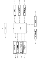
- FIG. 2 is a block diagram schematically showing a control configuration of the friction stir welding device shown in FIG.
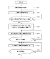
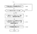
- FIG. 3A is a flowchart showing an example of the operation of the friction stir welding point joining device according to the first embodiment.
- FIG. 3B is a flowchart showing an example of the operation of the friction stir welding point joining device according to the first embodiment.
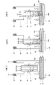
- FIG. 4A is a process diagram schematically showing an example of each process of friction stir point joining by the friction stir point joining device shown in FIG. 1.
- FIG. 4B is a process diagram schematically showing an example of each process of friction stir point joining by the friction stir point joining device shown in FIG. 1.
- FIG. 4A is a process diagram schematically showing an example of each process of friction stir point joining by the friction stir point joining device shown in FIG. 1.
- FIG. 4B is a process diagram schematically showing an example of each process of friction stir point joining by the friction
- FIG. 5A is a flowchart showing an example of the operation of the friction stir welding point joining device according to the second embodiment.
- FIG. 5B is a flowchart showing an example of the operation of the friction stir welding point joining device according to the second embodiment.
- FIG. 6A is a process diagram schematically showing an example of each process of friction stir point joining by the friction stir point joining device according to the second embodiment.
- FIG. 6B is a process diagram schematically showing an example of each process of friction stir point joining by the friction stir point joining device according to the second embodiment.
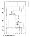
- FIG. 7 is a graph plotting the position of the tip of the shoulder member with respect to the joining time when the friction stir point joining device of Test Example 1 is used and the friction stir point joining is performed under the joining condition 1.
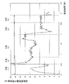
- FIG. 8 is a graph plotting the axial speed of the shoulder member with respect to the joining time when the friction stir point joining device of Test Example 1 is used and the friction stir point joining is performed under the joining condition 1.
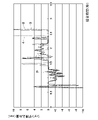
- FIG. 9 is a graph plotting the current values flowing through the rotary drive for the joining time when the friction stir point joining device of Test Example 1 is used and the friction stir point joining is performed under the joining condition 1.
- FIG. 10 is a graph plotting the current values flowing through the rotary drive for the joining time when the friction stir point joining device of Comparative Example 1 is used and the friction stir point joining is performed under the joining condition 2.
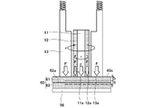
- FIG. 11 is an explanatory diagram of friction stir point joining by the friction stir point joining device according to the third embodiment.
- FIG. 12A is an explanatory diagram of a usage state in which a shoulder member is press-fitted into an object to be joined in the friction stir welding device according to the third embodiment.
- FIG. 12B is an explanatory diagram of a usage state in which a shoulder member of the friction stir welding point joining device according to the third embodiment is further press-fitted into the object to be joined as compared with FIG. 12A.
- FIG. 12C is an explanatory diagram of a usage state in which the friction stir welding device according to the third embodiment reaches the contact surface of the second member.
- FIG. 13 is a graph plotting the position of the tip of the shoulder member with respect to the joining time when the friction stir points are joined in Test Examples 2 and 3.
- FIG. 13 is a graph plotting the position of the tip of the shoulder member with respect to the joining time when the friction stir points are joined in Test Examples 2 and 3.
- FIG. 14 is a graph plotting the axial speed of the shoulder member with respect to the joining time when the friction stir points are joined in Test Examples 2, 3 and 4.
- FIG. 15 is a graph plotting the position of the tip of the shoulder member with respect to the joining time when the friction stir points are joined in Test Examples 5, 6 and 7.
- the friction stir point joining device is a friction stir point joining device having a first member and a second member and joining by softening the object to be joined by friction heat, and is a friction stir point joining device.
- the device has a pin member formed in a columnar shape, a shoulder member formed in a cylindrical shape in which the pin member is inserted, and a pin member and a shoulder member around an axis that coincides with the axis of the pin member. It is provided with a rotary drive for rotating the pin member and a forward / backward drive for moving the pin member and the shoulder member along the axis, respectively, and a controller, so that the first member faces the pin member and the shoulder member.
- the controller is The rotation drive and the advance / retreat drive are operated so that the pin member and the shoulder member press the joined portion of the object to be joined in a rotated state.
- the rotary drive and the advance / retreat drive are operated so that the pin member and the shoulder member agitate the object to be joined.
- the controller is in a state where the speed in the axial direction of the rotated shoulder member is a predetermined first speed set in advance.
- the set predetermined first time it may be determined that the tip of the shoulder member has reached the contact surface with the first member of the second member.
- the first speed in a state where the predetermined first speed is set in advance means a range of speeds.
- the state in which the first speed is reached means that the speed in the axial direction of the shoulder member is within the speed range of the first speed.
- the first speed may be ⁇ 0.5 mm / sec or more and + 0.5 mm / sec or less.
- the first time may be 0.01 seconds or more and 0.5 seconds or less.
- the controller determines that the tip of the shoulder member has reached the contact surface with the first member of the second member, and then the tip of the shoulder member.
- the advance / retreat drive and the rotary drive may be operated so as to reach a predetermined first position in the second member.
- the first position may be a position of 0.3 mm or less from the contact surface of the second member with the first member.
- the operation method of the friction stir point joining device is an operation method of a friction stir point joining device having a first member and a second member and joining by softening the object to be joined by frictional heat.
- the friction stir welding device has a pin member formed in a columnar shape, a shoulder member formed in a cylindrical shape, and a pin member inserted therein, and a pin member and a shoulder member shaft.
- a rotary drive that rotates around an axis that coincides with the center, an advance / retreat drive that moves the pin member and the shoulder member forward and backward along the axis, and a controller are provided, and the first member includes a pin member and a controller.
- the controller is The rotation drive and the advance / retreat drive are operated so that the pin member and the shoulder member press the joined portion of the object to be joined in a rotated state.
- the rotary drive and the advance / retreat drive are operated so that the pin member and the shoulder member agitate the object to be joined.
- the controller is in a state where the speed in the axial direction of the rotated shoulder member is a predetermined first speed set in advance. Then, when a predetermined first time set in advance has elapsed, it may be determined that the tip of the shoulder member has reached the contact surface of the second member with the first member.
- the first speed may be ⁇ 0.5 mm / sec or more and + 0.5 mm / sec or less.
- the first time may be 0.01 seconds or more and 0.5 seconds or less.
- the controller determines that the tip of the shoulder member has reached the contact surface with the first member of the second member, and then the shoulder member.
- the advance / retreat drive and the rotary drive may be operated so that the tip of the member reaches a predetermined first position in the second member.
- the first position may be a position of 0.3 mm or less from the contact surface with the first member of the second member.
- FIG. 1 is a schematic diagram showing a schematic configuration of a friction stir welding point joining device 50 according to the first embodiment.
- the vertical direction in the figure is represented as the vertical direction in the friction stir welding device 50.
- the friction stir welding point joining device 50 includes a pin member 11, a shoulder member 12, a tool fixing device 52, an advancing / retreating drive 53, a clamp member 13, and a backing support portion 55. It includes a backing member 56 and a rotary driver 57.
- the pin member 11, shoulder member 12, tool fixing device 52, advancing / retreating drive 53, clamp member 13, and rotary drive 57 are provided at the upper end of a backing support portion 55 composed of a C-type gun (C-type frame). Has been done. Further, a backing member 56 is provided at the lower end of the backing support portion 55. The pin member 11, the shoulder member 12, the clamp member 13, and the backing member 56 are attached to the backing support portion 55 at positions facing each other. The object to be joined 60 is arranged between the pin member 11, the shoulder member 12, the clamp member 13, and the backing member 56.
- the pin member 11, the shoulder member 12, and the clamp member 13 are fixed to the tool fixture 52 composed of the rotary tool fixture 521 and the clamp fixture 522. Specifically, the pin member 11 and the shoulder member 12 are fixed to the rotary tool fixture 521, and the clamp member 13 is fixed to the clamp fixture 522 via the clamp drive 41.
- the rotary tool fixture 521 is supported by the clamp fixture 522 via the rotary driver 57.
- the clamp drive 41 is composed of a spring.
- the pin member 11, the shoulder member 12, and the clamp member 13 are driven forward and backward in the vertical direction by the advance / retreat drive 53 composed of the pin drive 531 and the shoulder drive 532.
- the pin member 11 is formed in a columnar shape and is supported by a rotary tool fixture 521, although not shown in detail in FIG. Further, the pin member 11 is rotated by the rotation driver 57 around the axis Xr (rotation axis) corresponding to the axis of the pin member 11, and is rotated by the pin drive 531 in the arrow P1 direction, that is, in the axis Xr direction (FIG. 1). In the vertical direction), it is configured to be able to move forward and backward.
- the pin drive 531 may be composed of, for example, a linear actuator.
- the linear actuator may be composed of, for example, a servomotor and a rack and pinion, a servomotor and a ball screw, an air cylinder, or the like.
- the shoulder member 12 is formed in a cylindrical shape having a hollow shape, and is supported by the rotary tool fixture 521.
- a pin member 11 is inserted in the hollow of the shoulder member 12.
- the shoulder member 12 is arranged so as to surround the outer peripheral surface of the pin member 11.
- the shoulder member 12 is configured to be rotated around the same axis Xr as the pin member 11 by the rotation drive 57, and can be moved forward and backward along the arrow P2 direction, that is, the axis Xr direction by the shoulder drive 532. There is.
- the shoulder drive 532 may be composed of, for example, a linear actuator.
- the linear actuator may be composed of, for example, a servomotor and a rack and pinion, a servomotor and a ball screw, an air cylinder, or the like.
- the pin member 11 and the shoulder member 12 (rotating tool) are both supported by the same rotary tool fixture 521 in the present embodiment, and both are integrally rotated around the axis Xr by the rotary driver 57. do. Further, the pin member 11 and the shoulder member 12 are configured to be movable back and forth along the axis Xr direction by the pin drive 531 and the shoulder drive 532, respectively.
- the pin member 11 can move forward and backward independently, and the pin member 11 and the shoulder member 12 can move forward and backward as the shoulder member 12 moves forward and backward.
- Each may be configured to be able to move forward and backward independently.
- the clamp member 13 is formed in a cylindrical shape having a hollow shape, and is provided so that its axis coincides with the axis Xr.
- a shoulder member 12 is inserted in the hollow of the clamp member 13.
- the cylindrical shoulder member 12 is arranged so as to surround the outer peripheral surface of the pin member 11, and the cylindrical clamp member 13 is arranged so as to surround the outer peripheral surface of the shoulder member 12.
- the clamp member 13, the shoulder member 12, and the pin member 11 each have a coaxial core-shaped nested structure.
- the clamp member 13 is configured to press the object to be joined 60 from one surface (surface 60c). As described above, the clamp member 13 is supported by the clamp fixture 522 via the clamp drive 41 in the first embodiment.
- the clamp drive 41 is configured to urge the clamp member 13 toward the backing member 56 side.
- the clamp member 13 (including the clamp drive 41 and the clamp fixture 522) is configured to be able to advance and retreat in the arrow P3 direction (the same direction as the arrow P1 and the arrow P2) by the shoulder drive 532.
- clamp drive 41 is composed of a spring in the first embodiment, the clamp drive 41 is not limited to this.
- the clamp drive 41 may be configured to give a bias or a pressing force to the clamp member 13, and for example, a mechanism using gas pressure, hydraulic pressure, a servomotor or the like can also be preferably used.
- the pin member 11, the shoulder member 12, and the clamp member 13 have a tip surface 11a, a tip surface 12a, and a tip surface 13a, respectively. Further, the pin member 11, the shoulder member 12, and the clamp member 13 are moved back and forth by the advancing / retreating drive 53, so that the tip surface 11a, the tip surface 12a, and the tip surface 13a are each the surface 60c of the object to be joined 60. It comes into contact with (the portion to be joined of the object to be joined 60) and presses the object to be joined 60.
- the backing member 56 is configured to be supported by a flat surface (support surface 56a) so as to abut the back surface of the flat plate-shaped object to be joined 60.
- the structure of the backing member 56 is not particularly limited as long as it can appropriately support the object to be joined 60 so that friction stir welding can be performed.
- the backing member 56 may be configured such that, for example, a backing member 56 having a plurality of types of shapes is separately prepared and can be removed from the backing support portion 55 and replaced depending on the type of the object to be joined 60. good.
- the object to be joined 60 has two plate-shaped first members 61 and second members 62.
- the first member 61 is arranged so as to face the pin member 11 and the shoulder member 12, and is made of a material having a melting point lower than that of the second member 62.
- the sealant material may be applied to the contact portion between the first member 61 and the second member 62 of the material to be joined 60.
- the sealant material may be a sealing material or an adhesive.
- the sealant material for example, polysulfide-based synthetic rubber, natural rubber, silicone rubber, synthetic rubber such as fluororubber, synthetic resin such as tetrafluoroethylene rubber resin, and the like can be used.
- the first member 61 includes at least one of a metal material (for example, aluminum, aluminum alloy, magnesium alloy, etc.), a thermoplastic (for example, polyamide, etc.), and a fiber reinforced plastic (for example, carbon fiber reinforced plastic, etc.). Two materials may be used.
- a metal material for example, aluminum, aluminum alloy, magnesium alloy, etc.
- a thermoplastic for example, polyamide, etc.
- a fiber reinforced plastic for example, carbon fiber reinforced plastic, etc.
- Two materials may be used.
- the aluminum alloy various aluminum alloys can be used. For example, an Al—Mg—Si based alloy (A6061) may be used, or an Al—Si—Mg based alloy (AC4C) may be used.
- a metal material for example, steel, titanium, stainless steel, copper, etc.
- steel various types of steel can be used, and mild steel or high-strength steel may be used.
- an oxide film may be formed on the surface of the steel, or a plating layer (for example, zinc plating) may be formed.
- the galvanized steel sheet may be a hot-dip galvanized steel sheet (GI steel sheet), an alloyed hot-dip galvanized steel sheet (GA steel sheet), or a galvalume steel sheet (registered trademark). It may be an aluminum silicon-plated hot stamped steel sheet. Further, the thickness of the plating layer may be 2 ⁇ m to 50 ⁇ m.
- the object to be joined 60 is composed of a plate-shaped first member 61 and a plate-shaped second member 62 .
- the shape is not limited to this, and the shape of the object to be joined 60 (first member 61 and second member 62) is arbitrary, and may be, for example, a rectangular parallelepiped shape or an arc shape. Further, the object to be joined 60 may have three or more members.
- the specific configurations of the pin member 11, the shoulder member 12, the tool fixing device 52, the advancing / retreating drive 53, the clamp member 13, the backing support portion 55, and the rotary drive 57 in the first embodiment are described above.
- the configuration is not limited to this, and a configuration widely known in the field of friction stir welding can be preferably used.
- the pin drive 531 and the shoulder drive 532 may be composed of a motor, a gear mechanism, or the like known in the field of friction stir welding.
- the backing support portion 55 is composed of a C-type gun, but the present invention is not limited to this.
- the backing support portion 55 supports the pin member 11, the shoulder member 12, and the clamp member 13 so as to be able to move forward and backward, and the backing member 56 is provided at a position facing the pin member 11, the shoulder member 12, and the clamp member 13. It may be configured in any way as long as it can be supported.
- the first embodiment adopts a configuration including the clamp member 13, but the present invention is not limited to this, and a configuration without the clamp member 13 may be adopted.
- the clamp member 13 may be configured to be detachable from the backing support portion 55 as needed.
- the friction stir point joining device 50 adopts a form arranged in a friction stir point joining robot device (not shown). Specifically, the backing support portion 55 is attached to the tip of the arm of the robot device.
- the backing support portion 55 is also included in the friction stir welding robot device.
- the specific configuration of the friction stir point joining robot device including the backing support portion 55 and the arm is not particularly limited, and a configuration known in the field of friction stir welding such as an articulated robot can be preferably used. ..
- the friction stir point joining device 50 (including the backing support portion 55) is not limited to the case where it is applied to a friction stir point joining robot device, for example, an NC machine tool, a large C frame, or the like. It can also be suitably applied to known processing equipment such as an auto riveter.
- the friction stir point joining device 50 may adopt a form in which the object to be joined 60 is hand-held as long as it is possible to stably perform the friction stir point joining to the object to be joined 60.
- a form may be adopted in which the robot is used as the positioner of the object to be joined 60.
- FIG. 2 is a block diagram schematically showing a control configuration of the friction stir welding point joining device 50 shown in FIG.
- the friction stir welding point joining device 50 includes a controller 51, a storage device 31, an input device 32, a pressure detector 33, a position detector 34, a speed detector 35, and a time measuring device 36. ..
- the controller 51 controls each member (each device) constituting the friction stir welding point joining device 50. Specifically, the controller 51 reads and executes software such as a basic program stored in the storage device 31 to rotate drive the pin drive 531 and the shoulder drive 532 constituting the advance / retreat drive 53. The device 57 and the device 57 are controlled.
- the controller 51 may be configured by a single controller 51 that centrally controls, or may be configured by a plurality of controllers 51 that cooperate with each other to perform distributed control. Further, the controller 51 may be configured by a microcomputer, an MPU, a PLC (Programmable Logic Controller), a logic circuit, or the like.
- a microcomputer an MPU, a PLC (Programmable Logic Controller), a logic circuit, or the like.
- the storage device 31 stores a basic program and various data in a readable manner, and the storage device 31 is composed of a known memory, a storage device such as a hard disk, or the like.
- the storage device 31 does not have to be a single device, and may be configured as a plurality of storage devices (for example, a random access memory and a hard disk drive).
- the controller 51 and the like are configured by a microcomputer, at least a part of the storage device 31 may be configured as an internal memory of the microcomputer or may be configured as an independent memory.
- the data may be stored in the storage device 31 so that the data may be read from other than the controller 51, or the data may be written from the controller 51 or the like. Not to mention.
- the input device 32 can input various parameters related to the control of friction stir welding, other data, and the like to the controller 51, and is a known input device such as a keyboard, a touch panel, and a button switch group. It is configured.
- a known input device such as a keyboard, a touch panel, and a button switch group. It is configured.
- at least the joining conditions of the object to be joined 60 for example, data such as the thickness and material of the object to be joined 60 can be input by the input device 32.
- the pressurizing detector 33 detects the pressurizing force (pushing pressure) applied to the object to be joined 60 when the pin member 11 or the shoulder member 12 is in contact with or pressing against the object to be joined 60. , It is configured to output the detected pressing force to the controller 51.
- the load cell is used as the pressurizing detector 33, but the present invention is not limited to this, and a known pressurizing detector can be used.
- the position detector 34 is configured to detect the position information of the tip (tip surface 12a) of the shoulder member 12 and output the detected position information to the controller 51.
- the position detector 34 for example, a displacement sensor, an LVDT, an encoder, or the like may be used.
- the encoder may be configured to detect the rotation angle of the advancing / retreating drive 53 (shoulder drive 532) that drives the shoulder member 12 forward / backward.
- the position detector 34 may be an ammeter that detects the current value supplied to the advancing / retreating drive 53 (shoulder drive 532) that drives the shoulder member 12 forward / backward.
- the speed detector 35 is configured to detect the speed in the axial direction of the shoulder member 12 and output the detected speed information to the controller 51.
- an encoder that detects the rotation angle of the advancing / retreating drive 53 (shoulder drive 532) that drives the shoulder member 12 to advance / retreat may be used.
- the timekeeping device 36 has a clock function and / or a calendar function. Further, the timekeeping device 36 is configured to measure the time and output the measured time information to the controller 51.
- 3A and 3B are flowcharts showing an example of the operation of the friction stir welding point joining device 50 according to the first embodiment.
- 4A and 4B are process diagrams schematically showing an example of each process of friction stir point joining by the friction stir point joining device 50 shown in FIG. 1.
- FIGS. 4A and 4B show an example in which the first member 61 and the second member 62 are used as the object to be joined 60, and these are overlapped and connected by point joining. Further, in FIGS. 4A and 4B, a part of the friction stir welding device 50 is omitted, the arrow r indicates the rotation direction of the pin member 11 and the shoulder member 12, and the block arrow F indicates the first member 61 and The direction of the force applied to the second member 62 is shown.
- FIGS. 4A and 4B Although a force is applied to the first member 61 and the second member 62 from the backing member 56, they are not shown in FIGS. 4A and 4B for convenience of explanation. Further, in FIGS. 4A and 4B, the shoulder member 12 is shaded and hatched in order to clearly distinguish it from the pin member 11 and the clamp member 13.
- the operator places the object to be joined 60 on the support surface 56a of the backing member 56.
- the operator operates the input device 32 to input the joining execution of the object to be joined 60 to the controller 51.
- the robot may place the object to be joined 60 on the support surface 56a of the backing member 56.
- the controller 51 drives the rotation drive 57 to drive the pin member 11 and the shoulder member 12 at a predetermined first rotation speed (for example, 200 to 3000 rpm). Rotate (step S101; see step (1) in FIG. 4A).
- the controller 51 drives the advance / retreat drive 53 (shoulder drive 532) to rotate the pin member 11 and the shoulder member 12, and then holds the pin member 11, the shoulder member 12, and the clamp member 13. Bring it closer to the object to be joined 60. Then, the tip surface 11a of the pin member 11, the tip surface 12a of the shoulder member 12, and the tip surface 13a of the clamp member 13 (not shown in FIGS. 4A and 4B) are formed on the surface 60c of the object to be joined (object to be joined). (60 to be joined) (step S102; see step (2) in FIG. 4A).
- the controller 51 presses the object to be joined 60 with a predetermined pressing pressure (for example, a predetermined value included in the range of 3 kN to 15 kN) set in advance by the pin member 11, the shoulder member 12, and the clamp member 13.
- a predetermined pressing pressure for example, a predetermined value included in the range of 3 kN to 15 kN
- the advance / retreat drive 53 shoulder drive 532 is controlled so as to perform the operation.
- the controller 51 determines whether or not the pressurizing detector 33 has detected a predetermined pressure (for example, 3 kN to 15 kN) (step S103). Thereby, it can be determined whether or not the tip surface 11a of the pin member 11, the tip surface 12a of the shoulder member 12, and the tip surface 13a of the clamp member 13 are in contact with the surface 60c of the object to be joined 60.
- a predetermined pressure for example, 3 kN to 15 kN
- step S103 When the controller 51 determines that the pressurizing detector 33 has not detected a predetermined pressure (No in step S103), steps S102 and steps until the pressurizing detector 33 detects a predetermined pressure. The process of S103 is repeated.
- step S104 when the controller 51 determines that the pressurizing detector 33 has detected a predetermined pressure (Yes in step S103), the controller 51 executes the process of step S104.
- the clamp member 13 and the backing member 56 come into contact with each other.
- the first member 61 and the second member 62 are sandwiched. Then, due to the contraction of the clamp drive 41, the clamp member 13 is urged toward the surface 60c side of the object to be joined 60, and a clamping force is generated.
- the surface 60c of the object to be joined 60 is "preheated".
- the constituent material in the contact region of the first member 61 is softened by heat generation due to friction, and a plastic flow portion 60a is generated in the vicinity of the surface 60c of the object to be joined 60.
- step S104 the controller 51 drives the advancing / retreating drive 53 so that the tip surface 11a of the pin member 11 is immersed in the tip surface 12a of the shoulder member 12.
- the controller 51 may drive the advance / retreat drive 53 (pin drive 531) so that the pin member 11 is separated from the object to be joined 60.
- the controller 51 may drive the advance / retreat drive 53 (shoulder drive 532) so that the shoulder member 12 is press-fitted into the object to be joined 60.
- the tip end portion of the shoulder member 12 is press-fitted into the joined portion of the object to be joined 60 in a rotated state.
- the controller 51 acquires speed information in the axial direction of the shoulder member 12 detected by the speed detector 35 from the speed detector 35 (step S105). Next, the controller 51 determines whether or not the speed information (speed) acquired in step S105 is a predetermined first speed set in advance (step S106).
- the first member 61 and the second member 62 are made of different metals, and the second member 62 is made of a material (hard material) having a melting point higher than that of the first member 61. Therefore, when the tip (tip surface 12a) of the shoulder member 12 reaches the contact surface 62a of the second member 62 with the first member 61, the speed of the shoulder member 12 in the axial direction decreases.
- the first speed can be set in advance by an experiment or the like, and is appropriately set according to the composition of the second member 62 or the like.
- the first speed may be ⁇ 0.5 mm / sec or more and + 0.5 mm / sec or less from the viewpoint of the detection accuracy of the speed detector 35.
- step S105 determines that the speed information acquired in step S105 is not the first speed (No in step S106)
- the controller 51 returns to step S105, and the speed information acquired in step S105 becomes the first speed. Until then, the processes of steps S105 and S106 are repeated.
- step S105 determines that the speed information acquired in step S105 is the first speed (Yes in step S106)
- the controller 51 acquires time information from the timekeeping device 36 (step S107). Specifically, the controller 51 acquires from the time measuring device 36 the time elapsed since the speed information acquired in step S105 is determined to be the first speed.
- the controller 51 determines whether or not the time information (time elapsed since the determination of the first speed) acquired in step S107 has elapsed the preset first time (step S108). ..
- the time elapsed since the speed in the axial direction of the shoulder member 12 becomes the first speed is measured for the following reason. That is, as soon as the tip (tip surface 12a) of the shoulder member 12 reaches the contact surface 62a of the second member 62 with the first member 61, the tip of the shoulder member 12 is inside the second member 62. Will not be press-fitted into.
- the first time can be set in advance by an experiment or the like.
- the difference between the melting points (hardness) of the first member 61 and the second member 62 when the difference between the melting points (hardness) of the first member 61 and the second member 62 is small, for example, it may be 0.01 seconds or more, or 0.05 seconds or more. It may be 0.1 seconds or longer, or 0.2 seconds or longer.
- the difference between the melting points (hardness) of the first member 61 and the second member 62 when the difference between the melting points (hardness) of the first member 61 and the second member 62 is large, it may be, for example, 0.5 seconds or less, or 0.4 seconds or less. There may be.
- step S107 determines that the time information acquired in step S107 does not elapse the first time (No in step S108)
- the controller 51 returns to step S107, and the time information acquired in step S107 is the first.
- the processing of step S107 and step S108 is repeated until one hour has elapsed.
- step S107 determines that the time information acquired in step S107 has passed the first time (Yes in step S108)
- the position detector 34 obtains the position information of the tip of the shoulder member 12. Acquire (step S109; see FIG. 3B).
- step S109 determines whether or not the position information of the tip of the shoulder member 12 acquired in step S109 has reached a predetermined first position set in advance (step S110).
- the first position can be set in advance by an experiment or the like, and is an arbitrary position between the contact surface 62a of the second member 62 with the first member 61 and 0.3 mm or less.
- the first position is 0.008 mm or more from the contact surface 62a from the viewpoint of removing the plating layer (plating film) or oxide film formed on the second member 62 to form a new surface. It may be at a position of 0.01 mm or more from the contact surface 62a. Further, the first position may be a position of 0.25 mm or less from the contact surface 62a, or 0.20 mm or less from the contact surface 62a, from the viewpoint of suppressing wear (damage) of the shoulder member 12. It may be present, and may be at a position of 0.10 mm or less from the contact surface 62a.
- the first position is a plating layer (plating) formed on the second member 62 from the viewpoint of removing the plating layer (plating film) or the oxide film formed on the second member 62 to form a new surface.
- the position may be 0.20 mm or less from the film) or the oxide film, or 0.10 mm or less from the plating layer (plating film) or the oxide film formed on the second member 62.
- the tip surface 12a of the shoulder member 12 reaches an arbitrary position (that is, the first position) within 0.3 mm from the contact surface 62a of the second member 62. Then, a new surface is formed on the portion of the second member 62 that is in contact with the shoulder member 12 and / or the portion of the second member 62 that is in contact with the plastic flow portion 60a.
- the plating layer (plating film) formed on the surface of the second member 62 or the impurities forming the oxide film (for example, zinc, iron oxide, etc.) also flow directly under the pin member 11. Further, a part of the impurities flows out of the outer peripheral surface of the tip portion of the shoulder member 12.
- step S109 determines that the position information of the tip of the shoulder member 12 acquired in step S109 has not reached the first position (No in step S110)
- the controller 51 returns to step S109 and acquires it in step S109.
- the processing of step S109 and step S110 is repeated until it is determined that the position information of the tip end portion of the shoulder member 12 has reached the first position.
- step S111 determines that the position information of the tip of the shoulder member 12 acquired in step S109 has reached the first position (Yes in step S110).
- step S111 the controller 51 drives the advance / retreat drive 53 (pin drive 531) so that the pin member 11 advances toward the object 60, and / or the controller 51 is the shoulder member 12. Drives the advance / retreat drive 53 (Shoulder drive 532) so as to move away from the object to be joined 60.
- the controller 51 controls the advancing / retreating drive 53 to align the tip surface 11a of the pin member 11 and the tip surface 12a of the shoulder member 12 to such an extent that almost no step is formed between them (they are flush with each other). ).
- the pin member 11 gradually advances toward the first member 61, and the shoulder member 12 retracts from the first member 61.
- the softened portion of the plastic flow portion 60a flows from directly under the pin member 11 to directly under the shoulder member 12 (recess formed by press-fitting the shoulder member 12).
- the tip surface 11a of the pin member 11 and the tip surface 12a of the shoulder member 12 move to the vicinity of the surface 60c of the object to be joined 60.
- the surface 60c of the object to be joined 60 is shaped to obtain a substantially flat surface to the extent that substantially no recess is formed (see step (4) in FIG. 4B).
- step S104 and / or step S111 the controller 51 sets the area of the tip surface of the pin member 11 to Ap, the area of the tip surface of the shoulder member 12 to As, and the press-fitting depth of the pin member 11 to Pp.
- the press-fitting depth of the shoulder member 12 is Ps
- the following equation (I) Ap ⁇ Pp + As ⁇ Ps Tx ⁇ ⁇ ⁇ (I)
- It is preferable to control the advance / retreat drive 53 so as to reduce the absolute value of the tool average position Tx defined in, and it is more preferable to control the advance / retreat drive 53 so that the tool average position Tx 0. .. Since the specific control for reducing the absolute value of the tool average position Tx is disclosed in detail in Japanese Patent Application Laid-Open No. 2012-196682, the description thereof is omitted here.
- the controller 51 may control the advancing / retreating drive 53 so that the tip surface 11a of the pin member 11 is located at the first position in the process of step S111. In this case, the controller 51 advances and retreats so that the tip surface 11a of the pin member 11 and the tip surface 12a of the shoulder member 12 are flush with each other after the tip surface 11a of the pin member 11 is located at the first position.
- the drive 53 may be controlled.
- the controller 51 drives the advancing / retreating drive 53 so as to separate the pin member 11, the shoulder member 12, and the clamp member 13 from the object to be joined 60 (step S112). Then, the controller 51 controls the rotation drive 57 to stop the rotation of the pin member 11 and the shoulder member 12 (step S113; see step (5) in FIG. 4B), and this program (the object to be joined 60). The joining process) is completed.
- the speed in the axial direction of the shoulder member 12 in the rotated state of the controller 51 becomes the first speed.
- the controller 51 arbitrarily places the tip of the shoulder member 12 at 0.3 mm or less from the contact surface 62a with the first member 61 of the second member 62.
- the advance / retreat drive 53 is configured to operate so as to reach the position (that is, the first position).
- the plating layer (plating film) or oxide film formed on the surface (contact surface 62a) of the second member 62 is removed by the tip end portion of the shoulder member 12, and a new surface is formed.
- the removed plating layer (plating film) or impurities (for example, zinc or the like) forming the oxide film flow directly under the pin member 11. Further, a part of the impurities flows out of the outer peripheral surface of the tip end portion of the shoulder member 12.
- the softened portion of the plastic flow portion 60a flows from directly under the pin member 11 to directly under the shoulder member 12 (recess created by press-fitting the shoulder member 12), the amount of impurities that flow out is the amount of the shoulder member. The amount of impurities flowing directly under 12 is reduced.
- the controller 51 has elapsed for the first time in a state where the speed in the axial direction of the shoulder member 12 in the rotated state is the first speed. After determining that, a mode is adopted in which the advance / retreat drive 53 is operated so that the tip of the shoulder member 12 reaches the first position, but the present invention is not limited to this.
- the shoulderer After the controller 51 determines that the first time has elapsed in the state where the speed in the axial direction of the shoulder member 12 in the rotated state is the first speed, the shoulderer is further until a predetermined second time elapses. It may be configured to wait for the movement of the member 12. Further, after determining that the second time has elapsed, the controller 51 drives the advancing / retreating drive 53 (pin drive 531) so that the pin member 11 advances toward the object to be joined 60, and / or. The controller 51 may be configured to drive the advance / retreat drive 53 (shoulder drive 532) so that the shoulder member 12 is separated from the object to be joined 60.
- the second time may be 0.1 seconds or longer, or 0.2 seconds or longer, from the viewpoint of forming a new surface on the surface of the second member 62. Further, the second time may be 0.8 seconds or less, or 0.75 seconds or less, from the viewpoint of suppressing excessive heat from being applied to the new surface formed on the surface of the second member 62. May be good.
- the friction stir welding device according to the second embodiment is the friction stir welding device according to the first embodiment, in which the speed in the axial direction of the pin member in a rotated state of the controller is set in advance. When a predetermined first time has elapsed in the state of the first speed of, it is determined that the tip of the pin member has reached the contact surface with the first member of the second member. ..
- the first speed may be ⁇ 0.5 mm / sec or more and + 0.5 mm / sec or less.
- the first time may be 0.01 seconds or more and 0.5 seconds or less.
- the controller determines that the tip of the pin member has reached the contact surface with the first member of the second member, and then the tip of the pin member.
- the advance / retreat drive and the rotary drive may be operated so as to reach a predetermined first position in the second member.
- the first position may be a position of 0.3 mm or less from the contact surface of the second member with the first member.
- the speed in the axial direction of the pin member in the rotated state of the controller is set.
- the preset predetermined first time elapses in the state where the preset predetermined first speed is reached, the tip of the pin member comes into contact with the first member of the second member. Is determined to have reached.
- the first speed may be ⁇ 0.5 mm / sec or more and + 0.5 mm / sec or less.
- the first time may be 0.01 seconds or more and 0.5 seconds or less.
- the controller determines that the tip of the pin member has reached the contact surface with the first member of the second member, and then the pin.
- the advance / retreat drive and the rotary drive may be operated so that the tip of the member reaches a predetermined first position in the second member.
- the first position may be a position of 0.3 mm or less from the contact surface with the first member of the second member.
- the friction stir point joining device 50 according to the second embodiment has the same basic configuration as the friction stir point joining device 50 according to the first embodiment, but has the same configuration as the position detector 34 and the speed detector 35. Is different.
- the position detector 34 is configured to detect the position information of the tip (tip surface 11a) of the pin member 11 and output the detected position information to the controller 51.
- the position detector 34 for example, a displacement sensor, an LVDT, an encoder, or the like may be used.
- the encoder may be configured to detect the rotation angle of the advance / retreat drive 53 (pin drive 531) that drives the pin member 11 to advance / retreat. Further, the position detector 34 may be an ammeter that detects the current value supplied to the advancing / retreating drive 53 (pin drive 531) that drives the pin member 11 to advance / retreat.
- the speed detector 35 is configured to detect the speed in the axial direction of the pin member 11 and output the detected speed information to the controller 51.
- an encoder that detects the rotation angle of the advance / retreat drive 53 (pin drive 531) that drives the pin member 11 to advance / retreat may be used.
- 5A and 5B are flowcharts showing an example of the operation of the friction stir welding point joining device 50 according to the second embodiment.
- 6A and 6B are process diagrams schematically showing an example of each process of friction stir point joining by the friction stir point joining device 50 according to the second embodiment.
- FIGS. 6A and 6B show an example in which the first member 61 and the second member 62 are used as the object to be joined 60, and these are overlapped and connected by point joining. Further, in FIGS. 6A and 6B, a part of the friction stir welding device 50 is omitted, the arrow r indicates the rotation direction of the pin member 11 and the shoulder member 12, and the block arrow F indicates the first member 61 and The direction of the force applied to the second member 62 is shown.
- FIGS. 6A and 6B Although a force is applied to the first member 61 and the second member 62 from the backing member 56, they are not shown in FIGS. 6A and 6B for convenience of explanation. Further, in FIGS. 6A and 6B, the shoulder member 12 is shaded and hatched in order to clearly distinguish it from the pin member 11 and the clamp member 13.
- the operator places the object to be joined 60 on the support surface 56a of the backing member 56.
- the operator operates the input device 32 to input the joining execution of the object to be joined 60 to the controller 51.
- the robot may place the object to be joined 60 on the support surface 56a of the backing member 56.
- the controller 51 drives the rotation drive 57 to drive the pin member 11 and the shoulder member 12 at a predetermined first rotation speed (for example, 200 to 3000 rpm). Rotate (step S201; see step (1) in FIG. 6A).
- the controller 51 drives the advance / retreat drive 53 (shoulder drive 532) to rotate the pin member 11 and the shoulder member 12, and then holds the pin member 11, the shoulder member 12, and the clamp member 13. Bring it closer to the object to be joined 60. Then, the tip surface 11a of the pin member 11, the tip surface 12a of the shoulder member 12, and the tip surface 13a of the clamp member 13 (not shown in FIGS. 6A and 6B) are formed on the surface 60c of the object to be joined (object to be joined). 60 to be joined) (step S202; see step (2) in FIG. 6A).
- the controller 51 presses the object to be joined 60 with a predetermined pressing pressure (for example, a predetermined value included in the range of 3 kN to 15 kN) set in advance by the pin member 11, the shoulder member 12, and the clamp member 13.
- a predetermined pressing pressure for example, a predetermined value included in the range of 3 kN to 15 kN
- the advance / retreat drive 53 shoulder drive 532 is controlled so as to perform the operation.
- the controller 51 determines whether or not the pressurizing detector 33 has detected a predetermined pressure (for example, from 3 kN to 15 kN) (step S203), so that the tip surface 11a of the pin member 11 and the shoulder member It can be determined whether or not the tip surface 12a of the 12 and the tip surface 13a of the clamp member 13 are in contact with the surface 60c of the object to be joined 60.
- a predetermined pressure for example, from 3 kN to 15 kN
- step S203 When the controller 51 determines that the pressurizing detector 33 has not detected a predetermined pressure (No in step S203), steps S202 and steps are taken until the pressurizing detector 33 detects a predetermined pressure. The process of S203 is repeated.
- step S203 when the controller 51 determines that the pressurizing detector 33 has detected a predetermined pressure (Yes in step S203), the controller 51 executes the process of step S204.
- the clamp member 13 and the backing member 56 come into contact with each other.
- the first member 61 and the second member 62 are sandwiched. Then, due to the contraction of the clamp drive 41, the clamp member 13 is urged toward the surface 60c side of the object to be joined 60, and a clamping force is generated.
- the surface 60c of the object to be joined 60 is "preheated".
- the constituent material in the contact region of the first member 61 is softened by heat generation due to friction, and a plastic flow portion 60a is generated in the vicinity of the surface 60c of the object to be joined 60.
- step S204 the controller 51 drives the advancing / retreating drive 53 so that the tip surface 11a of the pin member 11 projects with respect to the tip surface 12a of the shoulder member 12.
- the controller 51 may drive the advance / retreat drive 53 (pin drive 531) so that the pin member 11 is press-fitted into the object to be joined 60.
- the controller 51 may drive the advance / retreat drive 53 (shoulder drive 532) so that the shoulder member 12 is separated from the object to be joined 60.
- the tip end portion of the pin member 11 is press-fitted into the joined portion of the object to be joined 60 in a rotated state.
- the controller 51 acquires speed information in the axial direction of the pin member 11 detected by the speed detector 35 from the speed detector 35 (step S205). Next, the controller 51 determines whether or not the speed information (speed) acquired in step S205 is a predetermined first speed set in advance (step S206).
- step S205 determines that the speed information acquired in step S205 is not the first speed (No in step S206)
- the controller 51 returns to step S205, and the speed information acquired in step S205 becomes the first speed. Until then, the processes of steps S205 and S206 are repeated.
- step S205 determines that the speed information acquired in step S205 is the first speed (Yes in step S206)
- the controller 51 acquires time information from the timekeeping device 36 (step S207). Specifically, the controller 51 acquires from the time measuring device 36 the time elapsed since the speed information acquired in step S205 is determined to be the first speed.
- the controller 51 determines whether or not the time information (time elapsed since the determination of the first speed) acquired in step S207 has elapsed the preset first time (step S208). ..
- step S207 determines that the time information acquired in step S207 has not elapsed the first time (No in step S208).
- the controller 51 returns to step S207, and the time information acquired in step S207 is the first.
- the processing of step S207 and step S208 is repeated until one hour has elapsed.
- step S207 determines that the time information acquired in step S207 has passed the first time (Yes in step S208)
- the position detector 34 obtains the position information of the tip of the pin member 11. Acquire (step S209; see FIG. 6B).
- step S210 determines whether or not the position information of the tip of the pin member 11 acquired in step S209 has reached a predetermined first position set in advance (step S210).
- the first position can be set in advance by an experiment or the like, and is an arbitrary position between the contact surface 62a of the second member 62 with the first member 61 and 0.3 mm or less.
- the tip surface 11a of the pin member 11 reaches an arbitrary position (that is, the first position) within 0.3 mm from the contact surface 62a of the second member 62. Then, a new surface is formed on the portion of the second member 62 that is in contact with the pin member 11 and / or the portion of the second member 62 that is in contact with the plastic flow portion 60a.
- the softened material of the plastic flow portion 60a is pushed away by the pin member 11 and flows directly under the shoulder member 12 from directly under the pin member 11, so that the shoulder member 12 retracts and floats with respect to the pin member 11 (FIG. FIG. 6A step (3A)).
- step S209 determines that the position information of the tip of the pin member 11 acquired in step S209 has not reached the first position (No in step S210)
- the controller 51 returns to step S209 and acquires it in step S209.
- the processing of step S209 and step S210 is repeated until it is determined that the position information of the tip end portion of the pin member 11 has reached the first position.
- step S210 determines that the position information of the tip of the pin member 11 acquired in step S209 has reached the first position (Yes in step S210).
- step S211 the controller 51 drives the advancing / retreating drive 53 (shoulder drive 532) so that the shoulder member 12 advances toward the object 60, and / or the controller 51 is the pin member 11.
- the controller 51 controls the advancing / retreating drive 53 to align the tip surface 11a of the pin member 11 and the tip surface 12a of the shoulder member 12 to such an extent that almost no step is formed between them (they are flush with each other). ).
- the shoulder member 12 gradually advances toward the first member 61, and the pin member 11 retracts from the first member 61. At this time, the softened portion of the plastic flow portion 60a flows from directly under the shoulder member 12 to directly under the pin member 11.
- the tip surface 11a of the pin member 11 and the tip surface 12a of the shoulder member 12 move to the vicinity of the surface 60c of the object to be joined 60.
- the surface 60c of the object to be joined 60 is shaped to obtain a substantially flat surface to the extent that substantially no recess is formed (see step (4) in FIG. 6B).
- step S204 and / or step S211 of the controller 51 the area of the tip surface of the pin member 11 is Ap, the area of the tip surface of the shoulder member 12 is As, and the press-fitting depth of the pin member 11 is Pp.
- the press-fitting depth of the shoulder member 12 Ps
- the following equation (I) Ap ⁇ Pp + As ⁇ Ps Tx ⁇ ⁇ ⁇ (I)
- It is preferable to control the advance / retreat drive 53 so as to reduce the absolute value of the tool average position Tx defined in, and it is more preferable to control the advance / retreat drive 53 so that the tool average position Tx 0. .. Since the specific control for reducing the absolute value of the tool average position Tx is disclosed in detail in Japanese Patent Application Laid-Open No. 2012-196682, the description thereof is omitted here.
- the controller 51 may control the advance / retreat drive 53 so that the tip surface 12a of the shoulder member 12 is located at the first position in the process of step S211.
- the controller 51 advances and retreats so that the tip surface 11a of the pin member 11 and the tip surface 12a of the shoulder member 12 are flush with each other after the tip surface 12aa of the shoulder member 12 is located at the first position.
- the drive 53 may be controlled.
- the controller 51 drives the advancing / retreating drive 53 so as to separate the pin member 11, the shoulder member 12, and the clamp member 13 from the object to be joined (step S212). Then, the controller 51 controls the rotation drive 57 to stop the rotation of the pin member 11 and the shoulder member 12 (step S213; see step (5) in FIG. 6B), and this program (the object to be joined 60). The joining process) is completed.
- the speed in the axial direction of the pin member 11 in the rotated state of the controller 51 becomes the first speed. , Determine whether or not the first hour has passed.
- the controller 51 has elapsed for the first time in a state where the speed in the axial direction of the pin member 11 in the rotated state is the first speed. After determining that, a mode is adopted in which the advance / retreat drive 53 is operated so that the tip of the pin member 11 reaches the first position, but the present invention is not limited to this.
- the pin is further until a predetermined second time elapses.
- the movement of the member 11 may be made to stand by.
- the controller 51 drives the advancing / retreating drive 53 (shoulder drive 532) so that the shoulder member 12 advances toward the object to be joined 60, and / or.
- the controller 51 may drive the advance / retreat drive 53 (pin drive 531) so that the pin member 11 is separated from the object to be joined 60.
- Test Example 1 Using the friction stirring point joining device 50 according to the first embodiment, a joining test of the object to be joined 60 is performed, and the position of the tip of the shoulder member 12, the speed in the axial direction of the shoulder member 12, and the shoulder member 12 are determined. The value of the current flowing through the rotary drive 57 to be rotationally driven was plotted.
- the first position which is the target arrival position of the shoulder member 12, is set to a position 0.04 mm below the contact surface 62a of the second member 62 with the first member 61.
- the first rotation speed which is the rotation speed of the pin member 11 and the shoulder member 12, was 2000 rpm, and the pressing force of the pin member 11, the shoulder member 12, and the clamp member 13 was 14.7 kN.
- the first position which is the target arrival position of the shoulder member 12, is set to a position 0.06 mm below the contact surface 62a of the second member 62 with the first member 61.
- FIG. 7 is a graph plotting the position of the tip of the shoulder member with respect to the joining time when the friction stir point joining device 50 of Test Example 1 is used and the friction stir point joining is performed under the joining condition 1.
- FIG. 8 is a graph plotting the axial speed of the shoulder member with respect to the joining time when the friction stir point joining device 50 of Test Example 1 is used and the friction stir point joining is performed under the joining condition 1.
- FIG. 9 is a graph in which the current values passed through the rotary driver 57 are plotted against the joining time when the friction stir point joining device 50 of Test Example 1 is used and the friction stir point joining is performed under the joining condition 1.
- FIG. 10 is a graph in which the current values passed through the rotary driver 57 are plotted against the joining time when the friction stir point joining device 50 of Comparative Example 1 is used and the friction stir point joining is performed under the joining condition 2.
- the joining time means the elapsed time since the controller 51 started the joining program shown in FIGS. 3A and 3B.
- the surface 60c of the object to be joined 60 is defined as 0, and the direction of being press-fitted into the object to be joined 60 is positive, and the direction away from the object 60 is negative.
- the side facing the contact surface 62a of the second member 62 from the upper surface of the first member 61 (the surface 60c of the object to be joined 60) is set to be negative, and the contact surface 62a to the second member 62 is the first.
- the side of the member 61 facing the upper surface was set as a plus.
- each step from step (1) to step (5) corresponds to each step from step (1) to step (5) shown in FIGS. 4A and 4B.
- the tip position of the shoulder member 12 is located around 0.99 mm. It is considered that the reason why the tip position of the shoulder member 12 is located around 0.99 mm is that the shoulder member 12 bends due to the pressure applied to the shoulder member 12 and the measured load varies.
- the tip of the shoulder member 12 is located on the contact surface 62a of the second member 62 with the first member 61 between 1.3 and 1.9 seconds.
- the controller 51 determines whether or not the first time has elapsed in the state where the speed in the axial direction of the shoulder member 12 in the rotated state is the first speed, so that the tip of the shoulder member 12 can be moved. It was shown that it is possible to determine whether or not the contact surface 62a of the second member 62 with the first member 61 has been reached.
- the axial speed of the shoulder member 12 shows a value of ⁇ 0.3 mm / sec. It is probable that the tip of the shoulder member 12 was press-fitted into the second member 62 from the contact surface 62a with the first member 61 of the second member 62 and reached the first position.
- the third embodiment will be described using the friction stir welding point joining device 50 (see FIG. 1).
- the basic configuration of the friction stir point joining device 50 is the same as that of the friction stir point joining device 50 according to the first embodiment.
- a configuration different from that of the first embodiment will be described for the friction stir welding point joining device 50 and the operation method, and the description of the same configuration will be omitted.
- the double-headed arrow R represents a detection range including the contact surface 62a of the second member 62.
- This detection range R is a range in which the controller 51 determines whether or not the tip of the shoulder member 12 has reached the contact surface 62a.
- the double-headed arrow D represents the distance from the upper surface of the first member 61 (the surface 60c of the object to be joined 60) to the detection range R.
- the operation of the third embodiment is different from the operation of the first embodiment because the detection range R is set. As a result, the operations of step S105 and step S106 of FIG. 3A are different. The other operations of the third embodiment are the same as the operations of the first embodiment.
- steps S101 to S104 are executed in the same manner as the operation of the friction stir welding point joining device 50 according to the first embodiment described above. After that, further steps S105 and S106 are executed.
- steps S105 and S106 will be described with reference to FIGS. 12A, 12B and 12C.
- FIG. 12A shows the shoulder member 12 press-fitted into the object to be joined 60 in this step S105.
- the controller 51 acquires the speed information in the axial direction of the shoulder member 12. Further, the position detector 34 detects the tip position of the shoulder member 12. The controller 51 determines whether or not the tip of the shoulder member 12 is within the detection range R. The controller 51 repeats the process of step S105 until it is determined that the tip of the shoulder member 12 is in the detection range R. As shown in FIG. 12B, when the controller 51 determines that the tip of the shoulder member 12 is in the detection range R, the controller 51 executes step S106.
- step S106 determines in step S106 that the speed information acquired in step S105 is not the first speed, the controller 51 returns to step S105 and repeats the processes of step S105 and step S106.
- step S105 determines that the speed information acquired in step S105 is the first speed
- the controller 51 acquires time information from the timekeeping device 36 (step S107).
- the tip of the shoulder member 12 reaches the contact surface 62a of the second member 62.
- the controller 51 acquires from the time measuring device 36 the time elapsed since the speed information acquired in step S105 is determined to be the first speed.
- the controller 51 determines whether or not the time information (time elapsed since the determination of the first speed) acquired in step S107 has elapsed the preset first time (step S108). ..
- step S107 determines that the time information acquired in step S107 does not elapse the first time
- the controller 51 returns to step S107 until the time information acquired in step S107 elapses the first time. , Step S107 and step S108 are repeated.
- step S108 when the controller 51 determines that the time information acquired in step S107 has passed the first time, the steps after step S109 are executed as shown in FIG. 3B. ..
- the controller 51 determines whether or not the tip of the shoulder member 12 has reached the contact surface 62a of the second member 62 within the set detection range R.
- This detection range R is set as a range including the contact surface 62a of the second member 62.
- the friction stir welding point joining device 50 can determine with high accuracy whether or not the tip of the shoulder member 12 has reached the contact surface 62a of the second member 62.
- this detection range R is preferably smaller than the thickness of the first member 61.
- the detection range R is preferably 0.6 mm or less, more preferably 0.4 mm or less, and particularly preferably 0.2 mm or less. Further, by reducing the ratio of the thickness of the first member 61 to the detection range R, the erroneous determination of the controller 51 is further suppressed. From this viewpoint, the ratio of the thickness of the first member 61 to the detection range R is preferably 60% or less, more preferably 40% or less, particularly preferably 20% or less, and most preferably 10%. It is as follows.
- the first time can be set short.
- the controller 51 can suppress erroneous determination. From the viewpoint of suppressing erroneous determination of the controller 51, the first time is preferably 0.05 seconds or longer.
- the storage device 31 stores the detection range R and the distance D corresponding to the object to be joined 60.
- the controller 51 determines whether or not the tip of the shoulder member 12 has reached the contact surface 62a of the second member 62 based on the detection range R stored in the storage device 31.
- the controller 51 may correct the detection range R.
- the position detector 34 detects the position of the tip of the shoulder member 12 in contact with the surface 60c of the object to be joined 60.
- the controller 51 acquires the position information that the tip of the shoulder member 12 abuts on the surface 60c (see FIG. 11) and the position information that is determined to have reached the abutment surface 62a (see FIG. 12C) of the second member 62. do.
- the controller 51 may correct the distance D and the detection range R shown in FIG. 11 based on these position information.
- the influence of variations in the thickness of the first member 61 and the thickness of the second member 62 can be suppressed.
- the detection range R can be set even smaller without removing the contact surface 62a.
- the correction is made based on the surface 60c of the object to be joined 60 and the contact surface 62a of the second member 62, but the correction is not limited to this.
- the thickness of the first member 61 may be measured, and the distance D and the detection range R may be corrected based on this thickness.
- the thickness of the object to be joined 60 may be measured, and the distance D and the detection range R may be corrected based on this thickness.
- the detection range R may be set to a range including the contact surface 62a of the second member 62.
- the detection range R may be determined by specifying the contact surface 62a of the second member 62 and using the contact surface 62a as the median without using the distance D.
- steps S109 and S110 it may be determined whether or not a predetermined holding time has elapsed, instead of determining whether or not the shoulder member 12 has reached the first position. That is, after the tip of the shoulder member 12 reaches the contact surface 62a of the second member 62, the rotation and pressing force of the shoulder member 12 are maintained. In this state, the controller 51 may determine whether or not the predetermined holding time has elapsed. After it is determined that the predetermined holding time has elapsed, the steps after step S111 may be executed.
- the friction stir point joining device 50 according to the first embodiment is used, but the setting of the detection range R can be similarly applied to the friction stir point joining device 50 according to the second embodiment.
- the controller 51 may be set with a detection range R including the contact surface 62a.
- this detection range R when the first time elapses in a state where the speed in the axial direction of the rotated pin member 11 becomes the first speed, the tip of the pin member 11 hits the second member 62. It may be determined that the contact surface 62a has been reached.
- Test Example 2 A joining test of the object to be joined 60 was performed using the friction stir point joining device 50 according to the third embodiment.
- step S108 after the tip of the shoulder member 12 reaches the contact surface 62a of the second member 62, the rotation and pressing force of the shoulder member 12 are maintained. This state was held for a predetermined holding time. After that, step S111 was executed. The holding time was 0.2 seconds.
- Other joining conditions are the same as the joining condition 1 of Test Example 1. That is, the rotation speeds of the first member 61, the second member 62, the pin member 11 and the shoulder member 12, and the pressing force of the pin member 11, the shoulder member 12, and the clamp member 13 are the same as in the joining condition 1. bottom.
- the detection range R was set to 0.6 mm. Specifically, the detection range R was set to +-(plus or minus) 0.3 mm with the contact surface 62a as the median value.
- the first time was 0.10 seconds.
- Test Example 3-4 In Test Example 3, the first hour was 0.05 seconds, and in Test Example 4, the first hour was 0.01 seconds. Other joining conditions were the same as in Test Example 2.
- Graph 2 in FIG. 13 is a graph plotting the position (pushing amount) of the tip of the shoulder member with respect to the joining time of Test Example 2.
- Graph 3 is a graph in which the position (pushing amount) of the tip of the shoulder member with respect to the joining time of Test Example 3 is plotted.
- Graph 2 in FIG. 14 is a graph plotting the axial speed of the shoulder member with respect to the joining time of Test Example 2.
- Graph 3 is a graph plotting the axial speed of the shoulder member with respect to the joining time of Test Example 3.
- Graph 4 is a graph plotting the axial speed of the shoulder member with respect to the joining time of Test Example 4.
- step S109 and step S110 it was determined in step S109 and step S110 whether or not the shoulder member 12 reached the first position.
- the detection range R was set to +-(plus or minus) 0.3 mm with respect to the contact surface 62a of the second member 62.
- the first time was set to 0.05 seconds, and the pushing amount to the first position was set to 0.10 mm.
- the pushing amount to the first position was 0.08 mm.
- Other joining conditions were the same as in Test Example 5.
- Test Example 7 the pushing amount to the first position was 0.05 mm. Other joining conditions were the same as in Test Example 5.
- Graph 5 in FIG. 15 is a graph plotting the position (pushing amount) of the tip of the shoulder member with respect to the joining time of Test Example 5.
- Graph 6 is a graph in which the position (pushing amount) of the tip of the shoulder member with respect to the joining time of Test Example 6 is plotted.
- Graph 7 is a graph in which the position (pushing amount) of the tip of the shoulder member with respect to the joining time of Test Example 7 is plotted.
- the joining time means the elapsed time since the controller 51 started the joining program shown in FIGS. 3A and 3B.
- the surface 60c of the object to be joined 60 is defined as 0, and the direction of being press-fitted into the object to be joined 60 is represented as a plus, and the direction away from the object to be joined 60 is represented as a minus.
- the direction in which the first member 61 is press-fitted from the upper surface is set to be negative, and the direction away from the first member 61 is set to be positive.
- the tip position of the shoulder member 12 is located around 0.99 mm when the joining time is between 1.3 and 1.6 seconds. It is considered that the tip position of the shoulder member 12 is located around 0.99 mm for the same reason as in FIG. 7.
- the tip of the shoulder member 12 is located on the contact surface 62a of the second member 62 with the first member 61 between 1.3 and 1.6 seconds. It is presumed that there is.
- the first member 61 and the second member 62 were joined by determining a predetermined holding time.
- the first member 61 and the second member 62 were joined without setting the pushing amount by the first position.
- the tip portion of the shoulder member 12 is press-fitted into the joined portion of the object to be joined 60 in a rotated state for 1.3 to 1.4 seconds. Then, the speed in the axial direction of the shoulder member 12 became 0 mm / sec. It is probable that this is because the first time was 0.01 seconds, and the speed at the position of the arrow P caused an erroneous determination that the tip of the shoulder member 12 reached the contact surface 62a of the second member 62. However, even when the first time is 0.01 seconds, it has been confirmed that no erroneous determination is made by reviewing the distance D and the detection range R.
- the time when the tip position of the shoulder member 12 is located around 1 mm is longer as the pushing amount to the first position is larger.
- the larger the pushing amount the longer the time.
- the controller 51 determined whether or not the first time had elapsed with the speed of the shoulder member 12 being the first speed in the detection range R. From this Test Example 2-7, it was confirmed that whether or not the tip of the shoulder member 12 reached the contact surface 62a of the second member 62 can be accurately determined in a short first time.
Landscapes
- Engineering & Computer Science (AREA)
- Mechanical Engineering (AREA)
- Pressure Welding/Diffusion-Bonding (AREA)
Priority Applications (6)
| Application Number | Priority Date | Filing Date | Title |
|---|---|---|---|
| US18/032,198 US12303995B2 (en) | 2020-10-15 | 2021-10-15 | Friction stir spot welder and method of operating friction stir spot welder |
| CN202180068362.2A CN116367950A (zh) | 2020-10-15 | 2021-10-15 | 搅拌摩擦点焊装置及其运行方法 |
| JP2022557478A JP7377374B2 (ja) | 2020-10-15 | 2021-10-15 | 摩擦攪拌点接合装置及びその運転方法 |
| EP21880218.9A EP4230338A4 (en) | 2020-10-15 | 2021-10-15 | Friction-stir spot welding device and method for operating same |
| JP2023185988A JP7787134B2 (ja) | 2020-10-15 | 2023-10-30 | 摩擦攪拌点接合装置及びその運転方法 |
| US19/187,299 US20250249531A1 (en) | 2020-10-15 | 2025-04-23 | Friction stir spot welder and method of operating friction stir spot welder |
Applications Claiming Priority (2)
| Application Number | Priority Date | Filing Date | Title |
|---|---|---|---|
| JP2020174152 | 2020-10-15 | ||
| JP2020-174152 | 2020-10-15 |
Related Child Applications (2)
| Application Number | Title | Priority Date | Filing Date |
|---|---|---|---|
| US18/032,198 A-371-Of-International US12303995B2 (en) | 2020-10-15 | 2021-10-15 | Friction stir spot welder and method of operating friction stir spot welder |
| US19/187,299 Continuation US20250249531A1 (en) | 2020-10-15 | 2025-04-23 | Friction stir spot welder and method of operating friction stir spot welder |
Publications (1)
| Publication Number | Publication Date |
|---|---|
| WO2022080483A1 true WO2022080483A1 (ja) | 2022-04-21 |
Family
ID=81208094
Family Applications (1)
| Application Number | Title | Priority Date | Filing Date |
|---|---|---|---|
| PCT/JP2021/038225 Ceased WO2022080483A1 (ja) | 2020-10-15 | 2021-10-15 | 摩擦攪拌点接合装置及びその運転方法 |
Country Status (5)
| Country | Link |
|---|---|
| US (2) | US12303995B2 (https=) |
| EP (1) | EP4230338A4 (https=) |
| JP (2) | JP7377374B2 (https=) |
| CN (1) | CN116367950A (https=) |
| WO (1) | WO2022080483A1 (https=) |
Cited By (2)
| Publication number | Priority date | Publication date | Assignee | Title |
|---|---|---|---|---|
| US20240001479A1 (en) * | 2020-12-04 | 2024-01-04 | Nippon Light Metal Company, Ltd. | Rotary tool, joining device, and joining method |
| JP2024010134A (ja) * | 2020-10-15 | 2024-01-23 | 川崎重工業株式会社 | 摩擦攪拌点接合装置及びその運転方法 |
Families Citing this family (4)
| Publication number | Priority date | Publication date | Assignee | Title |
|---|---|---|---|---|
| JP7223651B2 (ja) * | 2019-07-01 | 2023-02-16 | 川崎重工業株式会社 | 接合システム及びその運転方法 |
| EP4360796A4 (en) * | 2021-08-31 | 2024-10-16 | JFE Steel Corporation | FRICTION STIR POINT WELDED JOINT, MANUFACTURING METHOD THEREFOR AND FRICTION STIR POINT WELDING METHOD |
| JP2023152110A (ja) * | 2022-04-01 | 2023-10-16 | 川崎重工業株式会社 | 摩擦撹拌接合装置及びそのメンテナンス方法 |
| EP4552785A1 (en) * | 2023-11-10 | 2025-05-14 | Helmholtz-Zentrum hereon GmbH | Method and apparatus for performing double sided refill friction stir spot welding |
Citations (4)
| Publication number | Priority date | Publication date | Assignee | Title |
|---|---|---|---|---|
| JP2007118061A (ja) * | 2005-10-31 | 2007-05-17 | Osaka Industrial Promotion Organization | 摩擦撹拌接合方法及び装置 |
| JP2012196682A (ja) | 2011-03-18 | 2012-10-18 | Kawasaki Heavy Ind Ltd | 摩擦攪拌点接合装置および摩擦攪拌点接合方法 |
| JP2015180513A (ja) * | 2015-06-02 | 2015-10-15 | 川崎重工業株式会社 | 摩擦攪拌点接合装置および摩擦攪拌点接合方法 |
| JP2020127954A (ja) | 2019-02-08 | 2020-08-27 | トヨタ自動車株式会社 | 異種金属接合方法 |
Family Cites Families (6)
| Publication number | Priority date | Publication date | Assignee | Title |
|---|---|---|---|---|
| EP1884308B1 (en) * | 2006-08-04 | 2010-04-28 | Sumitomo Light Metal Industries, Ltd. | Method of friction stir welding together dissimilar metal members with a double acting rotary tool for filling of the hole created by the probe |
| JP5815961B2 (ja) * | 2011-03-18 | 2015-11-17 | 川崎重工業株式会社 | 摩擦攪拌点接合装置および摩擦攪拌点接合方法 |
| JP6244041B2 (ja) * | 2014-10-23 | 2017-12-06 | 川崎重工業株式会社 | 摩擦攪拌点接合装置及び摩擦攪拌点接合方法 |
| WO2017047574A1 (ja) * | 2015-09-14 | 2017-03-23 | 川崎重工業株式会社 | 摩擦攪拌点接合装置及び摩擦攪拌点接合方法 |
| KR102315903B1 (ko) * | 2017-09-04 | 2021-10-21 | 카와사키 주코교 카부시키 카이샤 | 복동식 마찰 교반 접합 장치의 운전 방법 및 복동식 마찰 교반 접합 장치 |
| JP7377374B2 (ja) | 2020-10-15 | 2023-11-09 | 川崎重工業株式会社 | 摩擦攪拌点接合装置及びその運転方法 |
-
2021
- 2021-10-15 JP JP2022557478A patent/JP7377374B2/ja active Active
- 2021-10-15 US US18/032,198 patent/US12303995B2/en active Active
- 2021-10-15 EP EP21880218.9A patent/EP4230338A4/en active Pending
- 2021-10-15 CN CN202180068362.2A patent/CN116367950A/zh active Pending
- 2021-10-15 WO PCT/JP2021/038225 patent/WO2022080483A1/ja not_active Ceased
-
2023
- 2023-10-30 JP JP2023185988A patent/JP7787134B2/ja active Active
-
2025
- 2025-04-23 US US19/187,299 patent/US20250249531A1/en active Pending
Patent Citations (4)
| Publication number | Priority date | Publication date | Assignee | Title |
|---|---|---|---|---|
| JP2007118061A (ja) * | 2005-10-31 | 2007-05-17 | Osaka Industrial Promotion Organization | 摩擦撹拌接合方法及び装置 |
| JP2012196682A (ja) | 2011-03-18 | 2012-10-18 | Kawasaki Heavy Ind Ltd | 摩擦攪拌点接合装置および摩擦攪拌点接合方法 |
| JP2015180513A (ja) * | 2015-06-02 | 2015-10-15 | 川崎重工業株式会社 | 摩擦攪拌点接合装置および摩擦攪拌点接合方法 |
| JP2020127954A (ja) | 2019-02-08 | 2020-08-27 | トヨタ自動車株式会社 | 異種金属接合方法 |
Non-Patent Citations (1)
| Title |
|---|
| See also references of EP4230338A4 |
Cited By (4)
| Publication number | Priority date | Publication date | Assignee | Title |
|---|---|---|---|---|
| JP2024010134A (ja) * | 2020-10-15 | 2024-01-23 | 川崎重工業株式会社 | 摩擦攪拌点接合装置及びその運転方法 |
| JP7787134B2 (ja) | 2020-10-15 | 2025-12-16 | 川崎重工業株式会社 | 摩擦攪拌点接合装置及びその運転方法 |
| US20240001479A1 (en) * | 2020-12-04 | 2024-01-04 | Nippon Light Metal Company, Ltd. | Rotary tool, joining device, and joining method |
| US12145211B2 (en) * | 2020-12-04 | 2024-11-19 | Nippon Light Metal Company, Ltd. | Rotary tool, joining device, and joining method |
Also Published As
| Publication number | Publication date |
|---|---|
| JP2024010134A (ja) | 2024-01-23 |
| US12303995B2 (en) | 2025-05-20 |
| US20230390860A1 (en) | 2023-12-07 |
| EP4230338A4 (en) | 2025-01-01 |
| JPWO2022080483A1 (https=) | 2022-04-21 |
| JP7787134B2 (ja) | 2025-12-16 |
| CN116367950A (zh) | 2023-06-30 |
| JP7377374B2 (ja) | 2023-11-09 |
| EP4230338A1 (en) | 2023-08-23 |
| US20250249531A1 (en) | 2025-08-07 |
Similar Documents
| Publication | Publication Date | Title |
|---|---|---|
| JP7377374B2 (ja) | 摩擦攪拌点接合装置及びその運転方法 | |
| JP7489457B2 (ja) | 摩擦攪拌点接合装置及び継手構造 | |
| JP6244041B2 (ja) | 摩擦攪拌点接合装置及び摩擦攪拌点接合方法 | |
| JP7216551B2 (ja) | 摩擦攪拌点接合装置及び摩擦攪拌点接合方法 | |
| JP6670317B2 (ja) | 摩擦攪拌点接合装置及び摩擦攪拌点接合方法 | |
| WO2020179661A1 (ja) | 摩擦攪拌点接合装置、摩擦攪拌点接合された被接合物、及びショルダ部材 | |
| US20160184922A1 (en) | Friction point joining device and friction point joining method | |
| JP6321820B2 (ja) | 摩擦攪拌接合中の溶接ピンチップにかかる機械力を検出するための方法及び装置 | |
| WO2022009928A1 (ja) | 摩擦攪拌点接合装置及び摩擦攪拌点接合方法 | |
| JP6829343B1 (ja) | 摩擦攪拌点接合装置及びその運転方法 | |
| KR20060018236A (ko) | 스폿 용접 방법, 스폿 용접기 및 스폿 용접 로봇 | |
| WO2020218444A1 (ja) | 摩擦攪拌点接合装置及びその運転方法 | |
| JP4755447B2 (ja) | 摩擦撹拌装置および摩擦撹拌方法 | |
| JP6307005B2 (ja) | 摩擦攪拌点接合における接合状態の評価方法、並びに、この評価方法を用いた摩擦攪拌点接合装置 | |
| US20240189934A1 (en) | Apparatus and Method for Regulating the Position of a Tong-Shaped Tool | |
| Arumugam | An investigation into improving weld strengths during spot welding |
Legal Events
| Date | Code | Title | Description |
|---|---|---|---|
| 121 | Ep: the epo has been informed by wipo that ep was designated in this application |
Ref document number: 21880218 Country of ref document: EP Kind code of ref document: A1 |
|
| ENP | Entry into the national phase |
Ref document number: 2022557478 Country of ref document: JP Kind code of ref document: A |
|
| WWE | Wipo information: entry into national phase |
Ref document number: 18032198 Country of ref document: US |
|
| NENP | Non-entry into the national phase |
Ref country code: DE |
|
| ENP | Entry into the national phase |
Ref document number: 2021880218 Country of ref document: EP Effective date: 20230515 |
|
| WWG | Wipo information: grant in national office |
Ref document number: 18032198 Country of ref document: US |