WO2022079787A1 - 二流体ノズル噴霧装置 - Google Patents
二流体ノズル噴霧装置 Download PDFInfo
- Publication number
- WO2022079787A1 WO2022079787A1 PCT/JP2020/038588 JP2020038588W WO2022079787A1 WO 2022079787 A1 WO2022079787 A1 WO 2022079787A1 JP 2020038588 W JP2020038588 W JP 2020038588W WO 2022079787 A1 WO2022079787 A1 WO 2022079787A1
- Authority
- WO
- WIPO (PCT)
- Prior art keywords
- fluid nozzle
- liquid
- pressure
- regulator
- pressurized liquid
- Prior art date
- Legal status (The legal status is an assumption and is not a legal conclusion. Google has not performed a legal analysis and makes no representation as to the accuracy of the status listed.)
- Ceased
Links
Images



Classifications
-
- B—PERFORMING OPERATIONS; TRANSPORTING
- B05—SPRAYING OR ATOMISING IN GENERAL; APPLYING FLUENT MATERIALS TO SURFACES, IN GENERAL
- B05B—SPRAYING APPARATUS; ATOMISING APPARATUS; NOZZLES
- B05B7/00—Spraying apparatus for discharge of liquids or other fluent materials from two or more sources, e.g. of liquid and air, of powder and gas
- B05B7/02—Spray pistols; Apparatus for discharge
- B05B7/04—Spray pistols; Apparatus for discharge with arrangements for mixing liquids or other fluent materials before discharge
- B05B7/0416—Spray pistols; Apparatus for discharge with arrangements for mixing liquids or other fluent materials before discharge with arrangements for mixing one gas and one liquid
- B05B7/0483—Spray pistols; Apparatus for discharge with arrangements for mixing liquids or other fluent materials before discharge with arrangements for mixing one gas and one liquid with gas and liquid jets intersecting in the mixing chamber
-
- B—PERFORMING OPERATIONS; TRANSPORTING
- B05—SPRAYING OR ATOMISING IN GENERAL; APPLYING FLUENT MATERIALS TO SURFACES, IN GENERAL
- B05B—SPRAYING APPARATUS; ATOMISING APPARATUS; NOZZLES
- B05B7/00—Spraying apparatus for discharge of liquids or other fluent materials from two or more sources, e.g. of liquid and air, of powder and gas
- B05B7/02—Spray pistols; Apparatus for discharge
- B05B7/08—Spray pistols; Apparatus for discharge with separate outlet orifices, e.g. to form parallel jets, i.e. the axis of the jets being parallel, to form intersecting jets, i.e. the axis of the jets converging but not necessarily intersecting at a point
- B05B7/0807—Spray pistols; Apparatus for discharge with separate outlet orifices, e.g. to form parallel jets, i.e. the axis of the jets being parallel, to form intersecting jets, i.e. the axis of the jets converging but not necessarily intersecting at a point to form intersecting jets
- B05B7/0815—Spray pistols; Apparatus for discharge with separate outlet orifices, e.g. to form parallel jets, i.e. the axis of the jets being parallel, to form intersecting jets, i.e. the axis of the jets converging but not necessarily intersecting at a point to form intersecting jets with at least one gas jet intersecting a jet constituted by a liquid or a mixture containing a liquid for controlling the shape of the latter
-
- B—PERFORMING OPERATIONS; TRANSPORTING
- B05—SPRAYING OR ATOMISING IN GENERAL; APPLYING FLUENT MATERIALS TO SURFACES, IN GENERAL
- B05B—SPRAYING APPARATUS; ATOMISING APPARATUS; NOZZLES
- B05B7/00—Spraying apparatus for discharge of liquids or other fluent materials from two or more sources, e.g. of liquid and air, of powder and gas
- B05B7/02—Spray pistols; Apparatus for discharge
- B05B7/04—Spray pistols; Apparatus for discharge with arrangements for mixing liquids or other fluent materials before discharge
- B05B7/0416—Spray pistols; Apparatus for discharge with arrangements for mixing liquids or other fluent materials before discharge with arrangements for mixing one gas and one liquid
-
- B—PERFORMING OPERATIONS; TRANSPORTING
- B05—SPRAYING OR ATOMISING IN GENERAL; APPLYING FLUENT MATERIALS TO SURFACES, IN GENERAL
- B05B—SPRAYING APPARATUS; ATOMISING APPARATUS; NOZZLES
- B05B1/00—Nozzles, spray heads or other outlets, with or without auxiliary devices such as valves, heating means
- B05B1/30—Nozzles, spray heads or other outlets, with or without auxiliary devices such as valves, heating means designed to control volume of flow, e.g. with adjustable passages
- B05B1/3033—Nozzles, spray heads or other outlets, with or without auxiliary devices such as valves, heating means designed to control volume of flow, e.g. with adjustable passages the control being effected by relative coaxial longitudinal movement of the controlling element and the spray head
- B05B1/304—Nozzles, spray heads or other outlets, with or without auxiliary devices such as valves, heating means designed to control volume of flow, e.g. with adjustable passages the control being effected by relative coaxial longitudinal movement of the controlling element and the spray head the controlling element being a lift valve
- B05B1/3046—Nozzles, spray heads or other outlets, with or without auxiliary devices such as valves, heating means designed to control volume of flow, e.g. with adjustable passages the control being effected by relative coaxial longitudinal movement of the controlling element and the spray head the controlling element being a lift valve the valve element, e.g. a needle, co-operating with a valve seat located downstream of the valve element and its actuating means, generally in the proximity of the outlet orifice
-
- B—PERFORMING OPERATIONS; TRANSPORTING
- B05—SPRAYING OR ATOMISING IN GENERAL; APPLYING FLUENT MATERIALS TO SURFACES, IN GENERAL
- B05B—SPRAYING APPARATUS; ATOMISING APPARATUS; NOZZLES
- B05B12/00—Arrangements for controlling delivery; Arrangements for controlling the spray area
- B05B12/02—Arrangements for controlling delivery; Arrangements for controlling the spray area for controlling time, or sequence, of delivery
-
- B—PERFORMING OPERATIONS; TRANSPORTING
- B05—SPRAYING OR ATOMISING IN GENERAL; APPLYING FLUENT MATERIALS TO SURFACES, IN GENERAL
- B05B—SPRAYING APPARATUS; ATOMISING APPARATUS; NOZZLES
- B05B7/00—Spraying apparatus for discharge of liquids or other fluent materials from two or more sources, e.g. of liquid and air, of powder and gas
- B05B7/02—Spray pistols; Apparatus for discharge
- B05B7/04—Spray pistols; Apparatus for discharge with arrangements for mixing liquids or other fluent materials before discharge
-
- B—PERFORMING OPERATIONS; TRANSPORTING
- B05—SPRAYING OR ATOMISING IN GENERAL; APPLYING FLUENT MATERIALS TO SURFACES, IN GENERAL
- B05B—SPRAYING APPARATUS; ATOMISING APPARATUS; NOZZLES
- B05B7/00—Spraying apparatus for discharge of liquids or other fluent materials from two or more sources, e.g. of liquid and air, of powder and gas
- B05B7/02—Spray pistols; Apparatus for discharge
- B05B7/12—Spray pistols; Apparatus for discharge designed to control volume of flow, e.g. with adjustable passages
-
- B—PERFORMING OPERATIONS; TRANSPORTING
- B05—SPRAYING OR ATOMISING IN GENERAL; APPLYING FLUENT MATERIALS TO SURFACES, IN GENERAL
- B05B—SPRAYING APPARATUS; ATOMISING APPARATUS; NOZZLES
- B05B7/00—Spraying apparatus for discharge of liquids or other fluent materials from two or more sources, e.g. of liquid and air, of powder and gas
- B05B7/02—Spray pistols; Apparatus for discharge
- B05B7/12—Spray pistols; Apparatus for discharge designed to control volume of flow, e.g. with adjustable passages
- B05B7/1209—Spray pistols; Apparatus for discharge designed to control volume of flow, e.g. with adjustable passages the controlling means for each liquid or other fluent material being manual and interdependent
- B05B7/1236—Spray pistols; Apparatus for discharge designed to control volume of flow, e.g. with adjustable passages the controlling means for each liquid or other fluent material being manual and interdependent with three or more interdependent valves
-
- B—PERFORMING OPERATIONS; TRANSPORTING
- B05—SPRAYING OR ATOMISING IN GENERAL; APPLYING FLUENT MATERIALS TO SURFACES, IN GENERAL
- B05B—SPRAYING APPARATUS; ATOMISING APPARATUS; NOZZLES
- B05B7/00—Spraying apparatus for discharge of liquids or other fluent materials from two or more sources, e.g. of liquid and air, of powder and gas
- B05B7/24—Spraying apparatus for discharge of liquids or other fluent materials from two or more sources, e.g. of liquid and air, of powder and gas with means, e.g. a container, for supplying liquid or other fluent material to a discharge device
- B05B7/2489—Spraying apparatus for discharge of liquids or other fluent materials from two or more sources, e.g. of liquid and air, of powder and gas with means, e.g. a container, for supplying liquid or other fluent material to a discharge device an atomising fluid, e.g. a gas, being supplied to the discharge device
- B05B7/2491—Spraying apparatus for discharge of liquids or other fluent materials from two or more sources, e.g. of liquid and air, of powder and gas with means, e.g. a container, for supplying liquid or other fluent material to a discharge device an atomising fluid, e.g. a gas, being supplied to the discharge device characterised by the means for producing or supplying the atomising fluid, e.g. air hoses, air pumps, gas containers, compressors, fans, ventilators, their drives
-
- B—PERFORMING OPERATIONS; TRANSPORTING
- B05—SPRAYING OR ATOMISING IN GENERAL; APPLYING FLUENT MATERIALS TO SURFACES, IN GENERAL
- B05B—SPRAYING APPARATUS; ATOMISING APPARATUS; NOZZLES
- B05B7/00—Spraying apparatus for discharge of liquids or other fluent materials from two or more sources, e.g. of liquid and air, of powder and gas
- B05B7/24—Spraying apparatus for discharge of liquids or other fluent materials from two or more sources, e.g. of liquid and air, of powder and gas with means, e.g. a container, for supplying liquid or other fluent material to a discharge device
- B05B7/2489—Spraying apparatus for discharge of liquids or other fluent materials from two or more sources, e.g. of liquid and air, of powder and gas with means, e.g. a container, for supplying liquid or other fluent material to a discharge device an atomising fluid, e.g. a gas, being supplied to the discharge device
- B05B7/2494—Spraying apparatus for discharge of liquids or other fluent materials from two or more sources, e.g. of liquid and air, of powder and gas with means, e.g. a container, for supplying liquid or other fluent material to a discharge device an atomising fluid, e.g. a gas, being supplied to the discharge device a liquid being supplied from a pressurized or compressible container to the discharge device
Definitions
- the present invention relates to a two-fluid nozzle spraying device.
- a two-fluid nozzle spraying device that sprays fine particles obtained by crushing a liquid by mixing a liquid such as water with the gas using a high-speed flow of compressed gas is known.
- control device that measures the nozzle characteristics of the two-fluid nozzle that mixes and sprays the compressed gas and the pressurized liquid in advance, and controls the pressure or flow rate of the gas and the pressure or flow rate of the liquid given to the two-fluid nozzle.
- Two-fluid spray systems are known (see, eg, Patent Document 1).
- Japanese Unexamined Patent Publication No. 2017-176975 Japanese Unexamined Patent Publication No. 2013-09646 Japanese Unexamined Patent Publication No. 2019-209233 Japanese Patent No. 5898581
- the present invention has been made to solve the above-mentioned problems, and an object of the present invention is to provide a two-fluid nozzle spraying device capable of adjusting spraying with high accuracy with a simple configuration.
- the two-fluid nozzle atomizing device is a gas regulator that outputs a compressed gas of a predetermined pressure in the compressed gas supply system, and an application exceeding a predetermined pressure in the pressurized liquid supply system.
- a positive displacement pump that is equipped with a relief valve that returns the pressurized liquid to the liquid supply side and outputs the pressurized liquid, and a liquid regulator that outputs the pressurized liquid output by the positive displacement pump while maintaining a predetermined discharge pressure. It is characterized by having a needle valve, a two-fluid nozzle that mixes and sprays a compressed gas output by the gas regulator and a pressurized liquid output by the liquid regulator or the needle valve.
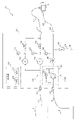
- FIG. 1 is a diagram showing a configuration example of a two-fluid nozzle spraying device 1 according to an embodiment.
- the two-fluid nozzle spraying device 1 has a spraying device main body 2 and a two-fluid nozzle 4, and utilizes a high-speed flow of compressed gas to mix a liquid such as water with a gas. It has a function to spray fine particles that are crushed liquid.
- the spraying device main body 2 has a compressed gas supply system 22 that flows a compressed gas that is a fluid from the gas supply port 20 side toward the gas discharge port 21 side and supplies the compressed gas to the bifluid nozzle 4. Further, the spray device main body 2 flows a pressurized liquid which is a fluid from the liquid supply port 23 side toward the liquid discharge port 24 side, and supplies the pressurized liquid to the bifluid nozzle 4. Has.
- a compressor 6 is connected to the gas supply port 20 via a pipe 10.
- the gas discharge port 21 is connected to the bifluid nozzle 4 via a pipe 11.
- the liquid supply port 23 is connected to the liquid tank 8 via the pipe 12.
- the liquid discharge port 24 is connected to the bifluid nozzle 4 via the pipe 13.
- the spraying device main body 2 is provided with a discharge port 26 for discharging a part of the liquid remaining in the pressurized liquid supply system 25 when the spraying of the two-fluid nozzle 4 is stopped.
- the discharge port 26 discharges a part of the liquid remaining in the pressurized liquid supply system 25 to the outside through the pipe 14.
- the pipes 10 to 14 are formed of, for example, a member having elasticity in part or in whole. Further, the pipes forming the compressed gas supply system 22 and the pressurized liquid supply system 25 are also formed of, for example, a member having elasticity in part or in whole. Therefore, even if pulsation occurs in the fluid, the influence of pulsation can be suppressed by the elastic piping.
- the spraying device main body 2 has, for example, a control unit 27 inside.
- the control unit 27 has a CPU 28 and a memory 29, has a function as a computer, and controls each control target constituting the spray device main body 2. The specific control target controlled by the control unit 27 will be described later.
- the two-fluid nozzle 4 applies the pressure of the compressed gas supplied from the compressed gas supply system 22 of the spraying device main body 2 to the pressurized liquid supplied from the pressurized liquid supply system 25 of the spraying device main body 2 in the anti-liquid flow direction.
- the compressed gas and the pressurized liquid are internally mixed and sprayed.
- the two-fluid nozzle 4 applies compressed gas to the pressurized liquid flowing in the central portion toward the spray port from two opposite directions so that the flowing liquid column is sandwiched between the two gas columns. It is a reverse pressure bifluid nozzle configured to be crushed and to spray the crushed liquid fine particles to the outside.
- the two-fluid nozzle 4 has a feature that liquid fine particles can be sprayed to the outside with a small amount of compressed gas.
- the compressor 6 compresses a gas such as air and supplies the compressed gas to the spraying device main body 2 via the pipe 10.
- the liquid tank 8 supplies a liquid such as water contained therein to the spraying device main body 2 via the pipe 12.
- the pipe 14 connected to the discharge port 26 may be provided so as to return the liquid discharged from the discharge port 26 to the liquid tank 8.
- the compressed gas supply system 22 has a gas regulator 30, a solenoid valve 31, a pressure gauge 32, a low pressure regulator 33, a solenoid valve 34, and a pressure gauge 35 in the compressed gas flow path from the gas supply port 20 to the gas discharge port 21. ..
- the gas regulator 30 outputs the gas supplied from the gas supply port 20 in the compressed gas supply system 22 as a compressed gas having a predetermined constant pressure to the gas discharge port 21 side via the solenoid valve 31.
- the solenoid valve 31 supplies or shuts off the compressed gas output by the gas regulator 30 to the gas discharge port 21 by turning it on or off according to the control of the control unit 27.
- the pressure gauge 32 detects the pressure of the compressed gas between the gas regulator 30 and the solenoid valve 31, for example, and outputs the detection result to the control unit 27.
- the pressure gauge 32 may be arranged so as to detect the pressure of the pipe between the solenoid valve 31 and the gas discharge port 21.
- the pressure gauge 32 may be removed after the setting of the predetermined gas regulator 30 for the spraying device main body 2 is completed.
- the low-pressure regulator 33 is provided in parallel with the gas regulator 30 in the compressed gas supply system 22, and the gas supplied from the gas supply port 20 is a low-pressure compressed gas having a predetermined constant pressure lower than that of the gas regulator 30. Output to the gas discharge port 21 side.
- the solenoid valve 34 supplies or shuts off the low-pressure compressed gas output by the low-pressure regulator 33 to the gas discharge port 21 by turning it on or off according to the control of the control unit 27.
- the pressure gauge 35 detects the pressure of the low-pressure compressed gas between the low-pressure regulator 33 and the solenoid valve 34, and outputs the detection result to the control unit 27, for example.
- the pressure gauge 35 may be removed after the predetermined setting for the spraying device main body 2 is completed. Further, when the pressure gauge 32 is arranged so as to detect the pressure of the pipe between the electromagnetic valve 31 and the gas discharge port 21, the pressure gauge 35 is not provided, and the pressure gauge 32 is the pressure gauge 35. It may also serve as a function.
- the pressurized liquid supply system 25 has a positive displacement pump 36, a liquid regulator 37, a pressure gauge 38, and an electromagnetic valve 39 in the pressurized liquid flow path from the liquid supply port 23 to the liquid discharge port 24.
- the positive displacement pump 36 has, for example, a diaphragm pump 360 and a relief valve 362, and starts or ends (stops) the operation according to the control of the control unit 27, for example.
- the diaphragm pump 360 is driven by a drive device such as a motor or solenoid (not shown), and adjusts the discharge amount according to the control of the control unit 27.
- the control unit 27 adjusts the discharge amount of the diaphragm pump 360 by adjusting the operating frequency of the drive device and the ratio of the operating period (on period) and the stopping period (off period) within a predetermined cycle.
- the diaphragm pump 360 is, for example, a self-sufficient pump, sucks the liquid contained in the liquid tank 8 through the liquid supply port 23 and the pipe 12, and feeds the liquid regulator 37 as a predetermined pressurized liquid. Output.
- the diaphragm pump 360 is characterized in that, for example, when the pressure on the liquid inlet side is -25 kPa to +350 kPa, a pressure of about +300 kPa to 600 kPa can be secured on the discharge side. Further, the diaphragm pump 360 is characterized in that the pressure on the liquid inlet side does not affect the discharge side and that the self-priming performance can be ensured by improving the airtightness of the check valve in the diaphragm pump 360. .. Therefore, the diaphragm pump 360 can be used in a wide range of supply liquid pressure conditions, such as when sucking liquid from an atmospheric pressure tank located 2.5 m below or when receiving liquid supply from a pressurized supply system such as water crew. Applicable. Further, the diaphragm pump 360 has almost no sliding portion and is easy to maintain.
- the relief valve 362 is provided in parallel with the diaphragm pump 360. Then, the relief valve 362 transfers the pressurized liquid exceeding the predetermined pressure in the pressurized liquid supply system 25 from the liquid output side (liquid regulator 37 side) of the diaphragm pump 360 to the liquid supply side (liquid supply port). It is returned to the 23 side) to prevent the inside of the diaphragm pump 360 from becoming too high pressure.
- the positive displacement pump 36 is provided with a self-sufficient diaphragm pump 360 here, it may be a pump having another configuration. Further, the diaphragm pump 360 and the relief valve 362 may be provided independently of each other.
- the liquid regulator 37 keeps the pressurized liquid output by the positive displacement pump 36 in the pressurized liquid supply system 25 at a constant discharge pressure of a predetermined value and outputs the pressurized liquid to the liquid discharge port 24. At this time, the liquid regulator 37 can suppress the influence of the pulsation even if the pressurized liquid output by the positive displacement pump 36 has a pulsation.
- the pressure gauge 38 detects the pressure of the pressurized liquid output by the liquid regulator 37, and outputs the detection result to the control unit 27.
- the pressure gauge 38 may be removed after the predetermined setting for the spraying device main body 2 is completed.
- the solenoid valve 39 is turned on or off according to the control of the control unit 27. Specifically, the solenoid valve 39 is a part or all of the pressurized liquid output by the liquid regulator 37 due to the pressure pressure or the lift difference from the two-fluid nozzle 4 when the spraying of the two-fluid nozzle 4 is stopped. Is a discharge valve that discharges the fluid from the pressurized liquid supply system 25 through the discharge port 26. For example, when the solenoid valve 39 is open, all or part of the liquid remaining in the pipe from the discharge side of the positive displacement pump 36 to the two-fluid nozzle 4 is discharged from the discharge port 26 by using the siphon principle or the like. It is possible.
- the two-fluid nozzle spraying device 1 controls the control unit 27 to close the solenoid valve 34 and the solenoid valve 39, open the solenoid valve 31, and operate the positive displacement pump 36. ..
- the spraying device main body 2 is supplied with compressed gas from the compressor 6 and is supplied with liquid from the liquid tank 8, the compressed gas is output from the gas discharge port 21 to the bifluid nozzle 4, and the pressurized liquid is supplied from the liquid discharge port 24. Is output to the two-fluid nozzle 4.
- the two-fluid nozzle 4 internally mixes the compressed gas supplied through the pipe 11 and the pressurized liquid supplied through the liquid supply port 23, and sprays the crushed liquid fine particles to the outside. ..
- control unit 27 controls, for example, the solenoid valve 31 and the positive displacement pump 36, and switches between supplying and shutting off the compressed gas and the pressurized liquid to the two-fluid nozzle 4, thereby reducing the spray amount of the two-fluid nozzle 4 for a long time.
- Proportional control For example, the control unit 27 controls the operation period (on period of the drive device) of the positive displacement pump 36 according to the spray amount at a constant cycle of about 30 seconds to 120 seconds.
- the control unit 27 stops the positive displacement pump 36 and the two-fluids.
- the supply of the pressurized fluid to the nozzle 4 is stopped, the solenoid valve 31 is closed, and the solenoid valve 34 is opened.
- the two-fluid nozzle spraying device 1 supplies the low-pressure compressed gas from the low-pressure regulator 33 to the two-fluid nozzle 4 to prevent dripping from the two-fluid nozzle 4 due to the air pressure from the low-pressure regulator 33.
- the control unit 27 closes the solenoid valve 34, stops the positive displacement pump 36 with the solenoid valve 31 open, and opens the solenoid valve 39 to connect the piping 13 and the like. The remaining liquid is discharged from the discharge port 26.
- the spraying device main body 2 accurately maintains the pressures of the compressed gas and the pressurized liquid at, for example, ⁇ 1 to 5 kPa of the target value, and outputs the pressure to the two-fluid nozzle 4.
- the two-fluid nozzle spraying device 1 has a gas regulator 30, a positive displacement pump 36, a liquid regulator 37, and a two-fluid nozzle 4, the two-fluid nozzle spraying device 1 has a simple configuration by combining the functions of each part. Has the effect of being able to adjust with high precision.
- FIG. 2 is a diagram showing a configuration example of a first modification (two-fluid nozzle spraying device 1a) of the two-fluid nozzle spraying device 1. It should be noted that the same reference numerals are given to the configurations substantially the same as those described above.
- the two-fluid nozzle spraying device 1a shown in FIG. 2 has a compressed gas supply system 22 and a pressurized liquid supply system 25a in the spraying device main body 2a.
- the pressurized liquid supply system 25a has a positive displacement pump 36, a needle valve 50, a pressure gauge 38, and a solenoid valve 39 in the pressurized liquid flow path from the liquid supply port 23 to the liquid discharge port 24.
- the difference from the first embodiment is that the needle valve 50 is used instead of the liquid regulator 37.
- the needle valve 50 is an electric openness adjustable valve.
- the needle valve 50 changes its opening degree according to the control of the control unit 27, and keeps the pressurized liquid output by the positive displacement pump 36 in the pressurized liquid supply system 25a at a predetermined discharge pressure to the liquid discharge port 24. Output. More specifically, the needle valve 50 has a Cv value of, for example, 0.05 to 1 when fully opened, and can control the flow rate of the pressurized liquid with higher accuracy than a valve having another configuration (for example, a ball valve). It is designed to be adjustable.
- a 15A size ball valve generally has a Cv value of 6.
- the two-fluid nozzle 4 is one, but a plurality of the two-fluid nozzles 4 are provided, a valve is provided on the liquid input side thereof, and the number of operations of the two-fluid nozzle 4 is changed to widen the spray amount. May change to.
- the head loss on the combined two-fluid nozzle 4 side as seen from the liquid discharge port 24 varies greatly depending on the number of operations of the two-fluid nozzle 4.
- such fluctuations can be dealt with by using an instrument such as the needle valve 50 whose opening degree can be adjusted with high accuracy.
- control unit 27 controls, for example, the solenoid valve 31, the positive displacement pump 36, and the needle valve 50, and switches between supplying and shutting off the compressed gas and the pressurized liquid to the two-fluid nozzle 4, thereby performing the first operation.
- the spray amount of the two-fluid nozzle 4 is controlled in proportion to time in the same manner as in the embodiment.
- control unit 27 controls at least one of the pressure of the compressed gas, the pressure of the pressurized liquid, and the opening degree of the needle valve 50 to control the spray characteristics (spray amount, particle diameter, etc.) of the two-fluid nozzle 4. To control.
- the control unit 27 shuts off the pressurized liquid from the two-fluid nozzle 4 by closing the needle valve 50 when the spraying of the two-fluid nozzle 4 is temporarily stopped. Then, the solenoid valve 31 is closed and the solenoid valve 34 is opened. Then, the two-fluid nozzle spraying device 1a supplies the low-pressure compressed gas from the low-pressure regulator 33 to the two-fluid nozzle 4 to prevent dripping from the two-fluid nozzle 4 due to the air pressure from the low-pressure regulator 33. Further, the case where the spraying is completely stopped is the same as that of the first embodiment, and thus the description thereof will be omitted.
- FIG. 3 is a diagram showing a configuration example of a second modification (two-fluid nozzle spraying device 1b) of the two-fluid nozzle spraying device 1. It should be noted that the same reference numerals are given to the configurations substantially the same as those described above.
- the two-fluid nozzle spraying device 1b shown in FIG. 3 has a compressed gas supply system 22b and a pressurized liquid supply system 25a in the spraying device main body 2b.
- the compressed gas supply system 22b has an electropneumatic regulator (EPR) 51 in the compressed gas flow path from the gas supply port 20 to the gas discharge port 21.
- EPR electropneumatic regulator
- the difference from the first modification of the two-fluid nozzle spraying device 1 shown in FIG. 2 is that the electropneumatic regulator 51 replaces the gas regulator 30, the low pressure regulator 33, the solenoid valves 31, 34, and the pressure gauges 32, 35. Is the point to use.
- the electropneumatic regulator 51 decompresses the gas supplied from the gas supply port 20 in the compressed gas supply system 22b according to the control of the control unit 27, and supplies the compressed gas of a predetermined pressure to the gas discharge port 21. Or shut off.
- the control unit 27 proportionally controls the spray amount of the two-fluid nozzle 4 by controlling the supply pressure of the compressed gas and the pressurized liquid to the two-fluid nozzle 4. Further, the control unit 27 controls the spray characteristics (spray amount, particle diameter, etc.) of the two-fluid nozzle 4 by controlling at least one of the pressure of the compressed gas and the pressure of the pressurized liquid.
- the pressure of the compressed gas or the pressure of the pressurized liquid may be changed according to the spray amount, or the supply pressure of the compressed gas and the supply of the pressurized liquid may be controlled as in the first embodiment.
- the spray amount may be controlled in proportion to time by blocking.
- the control unit 27 stops the positive displacement pump 36 to shut off the pressurized liquid to the bifluid nozzle 4 from the electropneumatic regulator 51.
- the control unit 27 stops the positive displacement pump 36 and opens the solenoid valve 39 in a state where the compressed gas of a predetermined pressure is supplied from the electropneumatic regulator 51 to the two-fluid nozzle 4.
- the liquid regulator 37 may be used instead of the needle valve 50.
- FIG. 4 is a diagram showing a configuration example of a third modification (two-fluid nozzle spraying device 1c) of the two-fluid nozzle spraying device 1. It should be noted that the same reference numerals are given to the configurations substantially the same as those described above.
- the liquid tank 8 is replaced with a water supply source 52 such as a water supply (or another pump) for the two-fluid nozzle spraying device 1 shown in FIG. It differs in that.
- the positive displacement pump 36 sucks up, for example, a liquid to which atmospheric pressure is applied and outputs the liquid to the liquid regulator 37.
- the positive displacement pump 36 sucks liquid from the water supply source 52 under pressure such as tap water and outputs the liquid to the liquid regulator 37. do.
- the spraying device main body 2 boosts the liquid to 0.3 to 0.6 MPa, which is higher than the general water supply pressure of 0.1 to 0.3 MPa for water services and the like. ing.
- the spraying device main body 2 makes it possible to suck up the liquid from the water supply source in a wide pressure range and spray it on the two-fluid nozzle 4, so that it is not necessary to pressurize the liquid in the liquid tank 8.
- each function of the control performed by the control unit 27 may be partially or wholly configured by hardware such as PLD (Programmable Logic Device) or FPGA (Field Programmable Gate Array), or a processor such as a CPU may be used. It may be configured as a program to be executed.
- hardware such as PLD (Programmable Logic Device) or FPGA (Field Programmable Gate Array)
- a processor such as a CPU may be used. It may be configured as a program to be executed.
- the low pressure regulator 33 when the loss of the compressed gas is negligible when the spraying of the two fluid nozzles 4 is temporarily stopped, the low pressure regulator 33.
- the pressure gauge 35 and the solenoid valve 34 may not be provided. In this case, even if the spraying of the two-fluid nozzle 4 is temporarily stopped, a compressed gas having the same pressure as during spraying may be supplied from the solenoid valve 31 to the two-fluid nozzle 4 to prevent dripping.
Landscapes
- Nozzles (AREA)
- Vaporization, Distillation, Condensation, Sublimation, And Cold Traps (AREA)
Abstract
Description
Claims (6)
- 圧縮気体供給系内で所定の圧力の圧縮気体を出力する気体用レギュレータと、
加圧液体供給系内で予め定められた圧力を超えた加圧液体を液体供給側へ帰還させるリリーフ弁を備え、加圧液体を出力する容積式ポンプと、
前記容積式ポンプが出力する加圧液体を所定値の吐出圧に保って出力する液体用レギュレータ又はニードル弁と、
前記気体用レギュレータが出力する圧縮気体と、前記液体用レギュレータ又は前記ニードル弁が出力する加圧液体とを混合させて噴霧する二流体ノズルと
を有することを特徴とする二流体ノズル噴霧装置。 - 前記二流体ノズルは、
前記液体用レギュレータ又は前記ニードル弁が出力する加圧液体に対し、前記気体用レギュレータが出力する圧縮気体の圧力を反液流方向に伝えつつ、圧縮気体と加圧液体とを内部混合させて噴霧すること
を特徴とする請求項1に記載の二流体ノズル噴霧装置。 - 前記二流体ノズルに対する加圧液体の供給と遮断とを切替えることにより、前記二流体ノズルの噴霧量を時間比例制御する制御部
をさらに有することを特徴とする請求項1に記載の二流体ノズル噴霧装置。 - 前記二流体ノズルの噴霧を停止させる場合に、前記二流体ノズルに対して加圧液体を遮断し、前記気体用レギュレータよりも低圧の圧縮気体を供給するように制御する制御部
をさらに有することを特徴とする請求項2に記載の二流体ノズル噴霧装置。 - 前記制御部は、
圧縮気体の圧力、加圧液体の圧力、及び前記ニードル弁の開度の少なくともいずれかを制御することにより、前記二流体ノズルの噴霧特性を制御すること
を特徴とする請求項3に記載の二流体ノズル噴霧装置。 - 前記二流体ノズルの噴霧を停止させた場合に、前記二流体ノズルからの気圧又は揚程差により、前記液体用レギュレータ又は前記ニードル弁が出力した加圧液体を加圧液体供給系から排出する排出弁
をさらに有することを特徴とする請求項1に記載の二流体ノズル噴霧装置。
Priority Applications (5)
| Application Number | Priority Date | Filing Date | Title |
|---|---|---|---|
| JP2022556711A JP7338799B2 (ja) | 2020-10-13 | 2020-10-13 | 二流体ノズル噴霧装置 |
| PCT/JP2020/038588 WO2022079787A1 (ja) | 2020-10-13 | 2020-10-13 | 二流体ノズル噴霧装置 |
| KR1020227014077A KR102624250B1 (ko) | 2020-10-13 | 2020-10-13 | 이류체 노즐 분무 장치 |
| CN202080072197.3A CN114630715B (zh) | 2020-10-13 | 2020-10-13 | 二流体喷嘴喷雾装置 |
| US17/755,440 US12311400B2 (en) | 2020-10-13 | 2020-10-13 | Twin-fluid nozzle spray apparatus |
Applications Claiming Priority (1)
| Application Number | Priority Date | Filing Date | Title |
|---|---|---|---|
| PCT/JP2020/038588 WO2022079787A1 (ja) | 2020-10-13 | 2020-10-13 | 二流体ノズル噴霧装置 |
Publications (1)
| Publication Number | Publication Date |
|---|---|
| WO2022079787A1 true WO2022079787A1 (ja) | 2022-04-21 |
Family
ID=81207885
Family Applications (1)
| Application Number | Title | Priority Date | Filing Date |
|---|---|---|---|
| PCT/JP2020/038588 Ceased WO2022079787A1 (ja) | 2020-10-13 | 2020-10-13 | 二流体ノズル噴霧装置 |
Country Status (5)
| Country | Link |
|---|---|
| US (1) | US12311400B2 (ja) |
| JP (1) | JP7338799B2 (ja) |
| KR (1) | KR102624250B1 (ja) |
| CN (1) | CN114630715B (ja) |
| WO (1) | WO2022079787A1 (ja) |
Families Citing this family (4)
| Publication number | Priority date | Publication date | Assignee | Title |
|---|---|---|---|---|
| KR102515210B1 (ko) * | 2022-06-24 | 2023-03-29 | (주)에코센스 | 비산 먼지 자동 제거 시스템 |
| KR102563366B1 (ko) * | 2022-12-06 | 2023-08-03 | 이주형 | 유체 분배 장치 |
| CN115921149A (zh) * | 2023-02-27 | 2023-04-07 | 浪潮金融信息技术有限公司 | 一种气液混合喷射装置、控制系统、控制方法及介质 |
| CN118616442A (zh) * | 2024-07-22 | 2024-09-10 | 青岛融合光电科技有限公司 | 一种二流体高效喷流系统 |
Citations (8)
| Publication number | Priority date | Publication date | Assignee | Title |
|---|---|---|---|---|
| JPS6167861U (ja) * | 1984-09-13 | 1986-05-09 | ||
| JPS6312363A (ja) * | 1986-07-04 | 1988-01-19 | Kansai Paint Co Ltd | 塗装装置 |
| JPH08131914A (ja) * | 1994-11-07 | 1996-05-28 | Abb Ransburg Kk | 塗装装置 |
| JP2004237188A (ja) * | 2003-02-05 | 2004-08-26 | Saniida:Kk | 洗浄液噴射装置 |
| JP2007139403A (ja) * | 2005-10-19 | 2007-06-07 | Sanki Eng Co Ltd | 二流体水噴霧ノズルの比例制御方法とその装置。 |
| JP2014066458A (ja) * | 2012-09-26 | 2014-04-17 | Toshiba Mitsubishi-Electric Industrial System Corp | 流体噴霧装置 |
| JP2017176975A (ja) * | 2016-03-29 | 2017-10-05 | 東芝三菱電機産業システム株式会社 | 二流体噴霧システム、二流体噴霧システム用制御装置 |
| WO2018179474A1 (ja) * | 2017-03-27 | 2018-10-04 | 東芝三菱電機産業システム株式会社 | 二流体噴霧装置 |
Family Cites Families (11)
| Publication number | Priority date | Publication date | Assignee | Title |
|---|---|---|---|---|
| DE19511482C2 (de) * | 1995-03-29 | 2000-01-20 | Argo Gmbh Fuer Fluidtechnik | Hydraulische Schaltung |
| KR100383282B1 (ko) * | 2000-05-04 | 2003-05-12 | 신선빈 | 페인트 분사 시스템 |
| US6883726B2 (en) * | 2002-01-16 | 2005-04-26 | The Toro Company | Fluid sprayer system using modulated control valve and a positive displacement pump |
| KR20040077521A (ko) * | 2003-02-28 | 2004-09-04 | 가부시키 가이샤 에바라 세이사꾸쇼 | 미스트생성장치 |
| KR20070025878A (ko) * | 2005-09-07 | 2007-03-08 | 경신공업 주식회사 | 차량용 어플리케이터 세척장치 |
| JP2013096648A (ja) | 2011-11-01 | 2013-05-20 | Toshiba Mitsubishi-Electric Industrial System Corp | 二流体ノズル装置 |
| JP5898581B2 (ja) | 2012-07-24 | 2016-04-06 | 東芝三菱電機産業システム株式会社 | 二流体噴霧装置、加圧液体供給装置 |
| JP2014034027A (ja) * | 2012-08-10 | 2014-02-24 | Toshiba Mitsubishi-Electric Industrial System Corp | 二流体噴霧装置 |
| JP6171040B2 (ja) * | 2016-04-05 | 2017-07-26 | 東芝三菱電機産業システム株式会社 | 二流体噴霧装置 |
| KR101833631B1 (ko) * | 2016-08-01 | 2018-03-05 | 주식회사 프로텍 | Emi 쉴드용 슬러리 도포 장치 |
| JP6927158B2 (ja) | 2018-05-31 | 2021-08-25 | 東芝三菱電機産業システム株式会社 | 噴霧装置 |
-
2020
- 2020-10-13 US US17/755,440 patent/US12311400B2/en active Active
- 2020-10-13 WO PCT/JP2020/038588 patent/WO2022079787A1/ja not_active Ceased
- 2020-10-13 JP JP2022556711A patent/JP7338799B2/ja active Active
- 2020-10-13 CN CN202080072197.3A patent/CN114630715B/zh active Active
- 2020-10-13 KR KR1020227014077A patent/KR102624250B1/ko active Active
Patent Citations (8)
| Publication number | Priority date | Publication date | Assignee | Title |
|---|---|---|---|---|
| JPS6167861U (ja) * | 1984-09-13 | 1986-05-09 | ||
| JPS6312363A (ja) * | 1986-07-04 | 1988-01-19 | Kansai Paint Co Ltd | 塗装装置 |
| JPH08131914A (ja) * | 1994-11-07 | 1996-05-28 | Abb Ransburg Kk | 塗装装置 |
| JP2004237188A (ja) * | 2003-02-05 | 2004-08-26 | Saniida:Kk | 洗浄液噴射装置 |
| JP2007139403A (ja) * | 2005-10-19 | 2007-06-07 | Sanki Eng Co Ltd | 二流体水噴霧ノズルの比例制御方法とその装置。 |
| JP2014066458A (ja) * | 2012-09-26 | 2014-04-17 | Toshiba Mitsubishi-Electric Industrial System Corp | 流体噴霧装置 |
| JP2017176975A (ja) * | 2016-03-29 | 2017-10-05 | 東芝三菱電機産業システム株式会社 | 二流体噴霧システム、二流体噴霧システム用制御装置 |
| WO2018179474A1 (ja) * | 2017-03-27 | 2018-10-04 | 東芝三菱電機産業システム株式会社 | 二流体噴霧装置 |
Also Published As
| Publication number | Publication date |
|---|---|
| KR20220069091A (ko) | 2022-05-26 |
| JP7338799B2 (ja) | 2023-09-05 |
| US20240299962A1 (en) | 2024-09-12 |
| CN114630715B (zh) | 2024-01-09 |
| KR102624250B1 (ko) | 2024-01-11 |
| US12311400B2 (en) | 2025-05-27 |
| JPWO2022079787A1 (ja) | 2022-04-21 |
| CN114630715A (zh) | 2022-06-14 |
Similar Documents
| Publication | Publication Date | Title |
|---|---|---|
| WO2022079787A1 (ja) | 二流体ノズル噴霧装置 | |
| US7054719B2 (en) | System and method for point of use delivery, control and mixing chemical and slurry for CMP/cleaning system | |
| US8540120B2 (en) | Fluid mixing and delivery system | |
| US7527768B2 (en) | Liquid dispenser with vacuum control | |
| US8869825B2 (en) | Flow rate control device | |
| US5301718A (en) | Apparatus and process for metering a low pressure fluid into a high pressure fluid flow | |
| US11661328B2 (en) | High ratio fluid control | |
| US9073176B2 (en) | Method for shot-peening and a shot-peening machine | |
| US20190270181A1 (en) | Vapor blast system with fixed pot pressure | |
| EP1701042A3 (de) | Hydraulische Steueranordnung | |
| US1025222A (en) | Liquid-pressure regulator. | |
| US6296226B1 (en) | Fluid metering system | |
| KR20120028967A (ko) | 액체 정량 토출 방법 및 장치 | |
| JPH11244757A (ja) | 液体吐出装置 | |
| CN117258863B (zh) | 高压微流体气压泵流量精细调控装置及多机协同控制系统 | |
| JP3701181B2 (ja) | 多液混合圧送装置 | |
| US3388866A (en) | Closed system recirculating assembly | |
| JP4658248B2 (ja) | 薬液供給システム | |
| JPH06294379A (ja) | 多液混合装置 | |
| JP2003284936A (ja) | 混合装置 | |
| JP2009265859A (ja) | 流量制御装置 | |
| CN119790360A (zh) | 用于两种不同气体的受控混合的气体混合装置 | |
| JPS6178456A (ja) | 液体の飛出し防止装置 | |
| JPH0710370B2 (ja) | 多液ポンプの硬化剤吐出チェック装置 | |
| JPH0771366A (ja) | 液供給量安定化装置、液供給装置および多液混合装置 |
Legal Events
| Date | Code | Title | Description |
|---|---|---|---|
| ENP | Entry into the national phase |
Ref document number: 20227014077 Country of ref document: KR Kind code of ref document: A |
|
| WWE | Wipo information: entry into national phase |
Ref document number: 17755440 Country of ref document: US |
|
| 121 | Ep: the epo has been informed by wipo that ep was designated in this application |
Ref document number: 20957616 Country of ref document: EP Kind code of ref document: A1 |
|
| ENP | Entry into the national phase |
Ref document number: 2022556711 Country of ref document: JP Kind code of ref document: A |
|
| NENP | Non-entry into the national phase |
Ref country code: DE |
|
| 122 | Ep: pct application non-entry in european phase |
Ref document number: 20957616 Country of ref document: EP Kind code of ref document: A1 |
|
| WWG | Wipo information: grant in national office |
Ref document number: 17755440 Country of ref document: US |