WO2022075340A1 - クレーン用情報処理装置 - Google Patents
クレーン用情報処理装置 Download PDFInfo
- Publication number
- WO2022075340A1 WO2022075340A1 PCT/JP2021/036901 JP2021036901W WO2022075340A1 WO 2022075340 A1 WO2022075340 A1 WO 2022075340A1 JP 2021036901 W JP2021036901 W JP 2021036901W WO 2022075340 A1 WO2022075340 A1 WO 2022075340A1
- Authority
- WO
- WIPO (PCT)
- Prior art keywords
- information processing
- crane
- suspended load
- processing apparatus
- processing device
- Prior art date
Links
Images


Classifications
-
- B—PERFORMING OPERATIONS; TRANSPORTING
- B66—HOISTING; LIFTING; HAULING
- B66C—CRANES; LOAD-ENGAGING ELEMENTS OR DEVICES FOR CRANES, CAPSTANS, WINCHES, OR TACKLES
- B66C13/00—Other constructional features or details
- B66C13/18—Control systems or devices
- B66C13/46—Position indicators for suspended loads or for crane elements
-
- B—PERFORMING OPERATIONS; TRANSPORTING
- B66—HOISTING; LIFTING; HAULING
- B66C—CRANES; LOAD-ENGAGING ELEMENTS OR DEVICES FOR CRANES, CAPSTANS, WINCHES, OR TACKLES
- B66C13/00—Other constructional features or details
- B66C13/18—Control systems or devices
- B66C13/48—Automatic control of crane drives for producing a single or repeated working cycle; Programme control
-
- B—PERFORMING OPERATIONS; TRANSPORTING
- B66—HOISTING; LIFTING; HAULING
- B66C—CRANES; LOAD-ENGAGING ELEMENTS OR DEVICES FOR CRANES, CAPSTANS, WINCHES, OR TACKLES
- B66C15/00—Safety gear
- B66C15/06—Arrangements or use of warning devices
Definitions
- the present invention relates to an information processing device that processes information acquired during operation of a crane that moves a suspended load within a fixed area.
- Patent Document 1 discloses a technique for specifying a horizontal position of a crane based on an image taken by a camera moving with the crane. If the position of the crane can be specified, it will be possible to utilize the crane for various purposes.
- Patent Document 2 discloses a technique for determining whether or not there is a person in a dangerous area around a suspended load by using a camera attached to a crane.
- the present invention has the first configuration corresponding to the problem (1).
- An information processing device that processes information acquired during the operation of a crane that moves suspended loads within a fixed area.
- a position detection unit that detects horizontal position information of a lifting device that is a device for lifting the suspended load in the crane and is installed so as to be movable in the horizontal direction.
- An operation record database that stores the location information in chronological order,
- the information processing device can be provided with a display control unit that reads out the position information from the operation record database and displays the movement locus of the lifting device.
- the movement locus of the hoisting device can be confirmed, and the operation record of the crane can be visually grasped. For example, if the entire movement trajectory of the day is displayed, it is possible to visually grasp in which area the crane was mainly operating and whether the total movement distance is normal or not.
- the display of the movement locus can also be provided in the form of a moving image in which the lifting device is moved along the movement locus.
- the information processing device including the operation record database may be provided integrally with the lifting device, or on a control device connected to the lifting device, a computer, or on the web connected via the Internet. It may be installed in the server of. Various selections can be made for the display destination of the movement locus. For example, a computer display, a tablet, a smartphone, or the like connected to an information processing device via a network or the like can be used.
- the location information can be specified by various methods.
- (1) Equipped with a camera that moves with the lifting device and captures the image below.
- (2) Mark the traveling rail on which the lifting device moves to specify the position. The marking is read by a sensor that moves with the lifting device. Based on the reading result, the position on the traveling rail and the position information of the lifting device may be specified.
- the position of the ranging sensor For the place where the crane is installed, store the positions of reference objects such as walls, equipment and obstacles in advance as a database. Based on the distance between the lifting device and the reference object measured by the ranging sensor, the position of the ranging sensor, and thus the position information of the lifting device may be specified. Not limited to the above-mentioned method, various methods can be adopted.
- storing the location information in the operation record database "in time series" means that the location information is stored in a manner that can specify the temporal order of the location information.
- the position information sorted in chronological order is not necessarily limited to the state in which the position information is sequentially stored in the memory area.
- the position information can be stored in various modes.
- the position information can be xy coordinates, latitude / longitude, or the like with respect to any point in the facility where the crane is installed.
- the time series mode (1) the position information and the aging are stored in association with each other, and (2) the position information is acquired at a predetermined time interval, and the start time and the position information are stored. After that, the position information and the order thereof can be associated and stored. Since the lifting device moves relatively linearly, after acquiring the position information, the position information that can be regarded as a straight line may be stored after being subjected to preprocessing. By doing so, the amount of data can be reduced.
- the operation record database stores the transportation information indicating whether or not the suspended load is being transported, together with the position information.
- the display control unit may visually discriminate between the movement locus during transportation of the suspended load and other movement loci.
- the display mode include a method of changing the color, line type, line thickness, and the like when displaying the movement locus between the state of transportation and the state of empty load.
- a predetermined mark may be displayed at the transportation start and transportation end points.
- others may be selectively displayed.
- only a specific transportation or only an empty state may be displayed, such as the first time and the second time during transportation.
- a camera that moves with the lifting device and captures the image below. It has an image database that stores image data taken by the camera in chronological order.
- the display control unit may display an image taken at each position on the movement locus.
- the image taken by the camera and the shooting position thereof can be easily grasped.
- the image may be either a still image or a moving image.
- the image data is stored in association with the position information or time of the lifting device.
- the image can be displayed in various modes. For example, when one point of the movement locus is designated by a mouse or the like, an image corresponding to that point may be displayed. In this case, if there is no image that completely corresponds to the specified position or time, the image closest to the position or time may be extracted and displayed.
- the image may be displayed by displaying the image taken at each point together with the moving image of moving the lifting device along the movement locus.
- the operation record database further stores operations on the lifting device in chronological order.
- the display control unit may display operations at each position on the movement locus.
- the operation may include not only the movement of the lifting device but also the operation of raising and lowering the suspended load. By doing so, it becomes possible to easily determine whether the lifting device is simply stopped or stopped due to the lifting and lowering of the suspended load.
- the operation data representing the contents of the operation can be stored in various aspects. For example, the position information of the lifting device and the operation data may be stored in association with each other.
- the operation data may be stored separately from the position information.
- the position information of the lifting device should not change. Therefore, if the operation data is stored individually, it is not necessary to store unnecessary position information, and the data as a whole. It is possible to control the amount.
- the display of the operation can be performed in various aspects. When a point on the movement locus is designated by a mouse or the like, the operation content corresponding to that point may be displayed. As another aspect, the image may be displayed by displaying the image taken at each point together with the moving image of moving the lifting device along the movement locus.
- the first configuration has a statistical processing unit that performs predetermined statistical processing on the operation of the lifting device based on the operation record database.
- the display control unit may display the result of the statistical processing in addition to the movement locus.
- Statistical processing includes, for example, calculation of the operating time of the information processing device, calculation of the total transportation time of the suspended load, the average transportation time, the total moving distance, the average moving distance, etc., the average moving speed of the hanging device, and the raising and lowering of the suspended load.
- the total time required for the operation, the calculation of the average value, and the total number of operations of the controller can be mentioned. Not only daily statistical processing but also weekly or monthly statistical processing may be performed, or daily, weekly, monthly comparison and the like may be performed.
- the present invention has a second configuration corresponding to the problem (2).
- An information processing device that processes information acquired during the operation of a crane that moves suspended loads within a fixed area.
- An operation record database that stores the operation record of the crane and Based on the operation record database, the information processing apparatus can be provided with a maintenance time determination unit for determining the maintenance time of the crane.
- the maintenance time can be determined based on the operation record, it is possible to avoid the failure that may occur before the periodic inspection at an early stage.
- Judgment of maintenance time includes judgment of necessity of maintenance.
- the operation record to be stored in the second configuration can be determined according to the method of determining the maintenance time. Examples of the operation results include the moving distance of the lifting device, the total weight of the suspended load carried, the number of times the crane controller is operated, the number of times the lifting device is moved / stopped, and the number of days elapsed after the periodic inspection.
- a method for determining the maintenance time either a method using machine learning or a method not based on machine learning may be used as described later.
- the maintenance time determination unit can also be provided in software on a control device connected to the lifting device, a computer, a server connected via the Internet, and the like. It does not matter if it is configured in terms of hardware.
- the maintenance time determination unit may determine the maintenance time by using a learning model for determining the maintenance time obtained by machine learning based on the past operation results of the crane.
- the maintenance time is not determined by a single factor among the various operational results mentioned above, but is considered to be influenced by the interaction of a plurality of factors.
- the learning model obtained by machine learning it is possible to make a judgment including such an interaction, and it is possible to improve the judgment accuracy of the maintenance time.
- various methods can be used to generate the learning model.
- the operation record used to determine the maintenance time and the operation record used to generate the learning model may be different. That is, a learning model may be generated based on a separately prepared operation record and applied to the information processing apparatus.
- a function for re-learning the learning model may be incorporated to reflect the operation results obtained by operating the crane.
- the operation results include the results of operation instructions for the crane.
- the learning model may be a learning model for determining the maintenance time of the controller of the crane, which is obtained based on the actual results of the operation instruction to the crane.
- the operator operates the controller to raise and lower the suspended load by the lifting device, and the crane is moved, so that a relatively large number of controller failures occur.
- the learning model obtained based on the actual results of the operation instructions is used, it is possible to accurately determine the maintenance time of the controller.
- the operation record database describes the relationship between the operation of the lifting device, which is a device for lifting the suspended load in the crane and is installed so as to be movable in the horizontal direction, and the reaction of the moving or stopping of the lifting device.
- the learning model may be a learning model for determining the maintenance time of the motor for moving the lifting device or the controller of the lifting device based on the relationship.
- an abnormality may occur in the reaction from the operation of the controller to the start or stop of movement.
- the same abnormality may occur in the precursors of poor contact or adhesion of the contacts of the controller.
- the operating results that can be used in the above embodiment include, for example, the reaction time from the operation to the start of movement or the start of stop, the acceleration or deceleration for the operation, the maximum speed reached during the operation, the stability of the speed during movement, and the like. Can be done.
- the operation record database stores at least one of the relationship between the vibration of the suspended load, the hoisting amount of the lifting device, and the suspended load height.
- the learning model may be a learning model for determining the maintenance time of the wire of the lifting device based on the data.
- Wire maintenance is important for cranes, but no efficient method has been found at present.
- a phenomenon such as a decrease in elasticity due to elongation or loosening of the wire may appear as a precursor.
- Such a phenomenon may appear in the behavior of a suspended load lifted by a crane.
- it is possible to accurately determine the maintenance time of the wire by using the behavior of the suspended load such as the vibration of the suspended load and the relationship between the hoisting amount of the lifting device and the height of the suspended load.
- the behavior of the suspended load can be detected by various methods.
- a device capable of acquiring a three-dimensional point cloud such as a camera capable of photographing a suspended load or a laser radar may be attached to the lifting device, and vibration may be obtained by analyzing the photographed image or the three-dimensional point cloud.
- a strain gauge may be attached to the wire itself to detect vibration of the wire itself. Further, the height of the suspended load is obtained by measuring the distance to the suspended load with a laser radar or the like mounted on the suspension device.
- the present invention can also be configured as a system for generating the learning model. That is, It is a learning model generation system that generates a learning model for determining the maintenance time of a crane that moves a suspended load in a fixed area. An operation record database that stores the operation record of the crane and A learning data generation unit that generates learning data by performing preset predetermined processing on the operation results of the operation record database. It is possible to provide a learning model generation system including a maintenance time determination model generation unit that generates a learning model for determining the maintenance time of the crane by machine learning using the learning data.
- learning data can be generated from the operation results, and a learning model can be generated based on the data.
- the training data can be generated in various modes depending on the content of the learning model. For example, based on the operation record, data showing the actual operation instruction, the relationship between the operation and the reaction of the movement or stop of the suspended load, the vibration of the suspended load, the hoisting amount of the lifting device and the suspended load height, etc. are generated. However, this can be used as learning data.
- supervised learning especially regression analysis, can be used if sufficient operational records of past failures have been obtained. Unsupervised learning is also useful, as shown below. Most of the crane operation results are considered to be data under normal operation.
- unsupervised learning is used to generate a learning model that determines a cluster of data indicating normal operation, it means that an abnormality is occurring if an operating record that tends to deviate from this cluster is obtained. Conceivable. This makes it possible to determine the maintenance time.
- the present invention has a third configuration corresponding to the problem (3).
- An information processing device that processes information acquired during the operation of a crane that moves suspended loads within a fixed area.
- An operation record database that identifies the positional relationship between the suspended load and a person or an obstacle in the vicinity of the suspended load while the crane is in operation and stores the positional relationship. Based on the operation record database, the information processing apparatus can be provided with a risk evaluation unit for determining the presence or absence of danger or the degree of danger in the operation of the crane.
- the positional relationship can be obtained by various methods.
- a device capable of acquiring a three-dimensional point cloud such as a camera or a laser radar capable of photographing the lower part may be attached to the lifting device, and the positional relationship may be obtained by analyzing the photographed image or the three-dimensional point cloud.
- the positional relationship includes the distance between the suspended load and a person or an obstacle in the vicinity thereof, the direction of a person or the like based on the moving direction of the suspended load, and the like.
- these positional relationships may be acquired as static information at a certain point in time, or may be acquired as dynamic information such as changes in the positional relationship over a certain period of time.
- dynamic information it is possible to grasp a series of work procedures, for example, an operator approaches a suspended load, contacts the suspended load, and then leaves the suspended load for a certain period of time.
- a method for determining the presence or absence of danger or its degree either a method using machine learning or a method not based on machine learning may be used as described later.
- the danger in the third configuration is not necessarily limited to the collision of the suspended load with a person or obstacle.
- the fall of the suspended load and the abnormal behavior of the suspended load are also included.
- the determination of these dangers can be made based on, for example, the positional relationship between the suspended load and the wire, whether the wire is attached to the suspended load by a predetermined procedure, and the like.
- the risk assessment unit may divide the transportation of the suspended load into a plurality of predetermined scenes, change the data and method used for each scene, and make the determination.
- the scenes of transporting a suspended load with a crane can be divided into several situations such as attaching wires to the suspended load, lifting, starting transportation, transporting, lowering the suspended load, and removing the wire. Since the work content is different in each situation, it is preferable to change the criteria for judging danger. According to the above aspect, since the data and the method to be used are changed for each of these situations, it is possible to make an accurate judgment.
- the above scenes are merely examples, and some of them may be omitted or may be further divided into more scenes.
- It has a basic operation determination unit that determines whether or not a worker involved in the transportation of the suspended load has performed a predetermined basic operation set in advance.
- the risk assessment unit may make the determination in consideration of the degree of implementation of the basic operation.
- the possibility of danger is determined by using the degree of implementation of the basic operation.
- the judgment of the basic operation can be performed by various methods. As will be described later, machine learning may be used. Further, for example, in the case of an operation such as pointing confirmation, the operator may determine whether or not the posture characteristic of the operation is taken based on an image or the like. If it can be confirmed that the worker has been in contact with the suspended load for a certain period of time, it may be determined that the predetermined inspection has been performed on the suspended load based on the confirmation.
- the risk assessment unit may determine the presence or absence of the danger or its degree by using a learning model for determining the danger obtained by machine learning based on the past operation results of the crane. ..
- the presence or absence of danger and its degree are not determined by a single factor among various operational results such as the positional relationship with the suspended load, but are influenced by the interaction of multiple factors.
- various methods can be used to generate the learning model.
- the operation record used to judge the danger and the operation record used to generate the learning model may be different. That is, a learning model may be generated based on a separately prepared operation record and applied to the information processing apparatus.
- a function for re-learning the learning model may be incorporated to reflect the operation results obtained by operating the crane.
- the risk assessment unit may specify the presence or absence of the danger or the degree of the danger together with the reason.
- the reason can be determined by various methods. For example, when a danger is judged without using machine learning, the cause of the judgment may be specified according to the judgment criteria used for the judgment. For example, when five judgment criteria A, B, C, D, and E are prepared and it is judged to be dangerous by the judgment standard A using the distance between the suspended load and a person as a standard, the judgment standard A. The "reason" is an element corresponding to the above, that is, "the distance to the suspended load is closer than the reference value".
- the operation record data used for the learning model may be shown as a reason.
- the reason should be obtained based on the node in which the direction judged to be dangerous is selected in the judgment process. You may do it.
- a device for lifting the suspended load in the crane which has a position detecting unit for detecting the horizontal position information of the lifting device installed so as to be movable in the horizontal direction.
- the operation record database stores the location information in chronological order.
- a display control that reads the position information from the operation record database, displays the movement locus of the hoisting device, and displays the judgment result by the risk evaluation unit in association with each position on the movement locus. It may be provided with a part.
- a camera that moves with the lifting device and captures the image below. It has an image database that stores image data taken by the camera in chronological order.
- the display control unit may display an image taken at each position on the movement locus.
- It has a basic operation database that stores image data representing the basic operation that should be originally performed when operating the lifting device.
- the risk assessment unit determines that it is dangerous, it selects the basic operation that should be performed from the basic operation database, and selects the basic operation that should be performed.
- the display control unit may display an image representing the selected basic operation by using the basic operation database.
- the present invention can also be configured as a system for generating the learning model. That is, it is a learning model generation system that generates a learning model for determining whether or not a basic operation for operating a crane that moves a suspended load is performed in a fixed area.
- a basic operation database that stores teacher data that represents the basic operations that should be performed, and Based on the teacher data, it is possible to provide a learning model generation system including a learning model generation unit for basic motion determination that generates a learning model for determining whether or not the basic motion is performed.
- the learning model can be generated based on the teacher data in which the basic operation is performed in advance. Since it is a learning model for determining whether or not the operation actually performed corresponds to this basic operation, it is a model for dealing with the classification problem.
- the teacher data can be prepared as a set of a series of still images representing the basic operation. Further, it is preferable to make an image in which only the movement of the operator is extracted. Since the actual determination is made based on the image taken by a camera or the like attached to the lifting device, it is preferable to use the image data taken under the same conditions as the teacher data.
- the learning model used for determining the danger in the third configuration may be generated by the learning model generation system shown below. That is, it is a learning model generation system that generates a learning model for determining the presence or absence and the degree of danger during operation of a crane that moves a suspended load within a fixed area. An operation record database that stores the past operation results of the crane and A learning data generation unit that reads the operation record database, divides the transportation of the suspended load into a plurality of predetermined scenes, and performs predetermined predetermined processing for each scene to generate learning data. It is a learning model generation system including a risk degree determination model generation unit that generates a learning model for determining the presence / absence and the degree of the danger for each of the scenes by machine learning using the learning data.
- the transportation of the suspended load into various scenes and generate a learning model for determining the danger for each scene.
- the accuracy can be improved. Since the learning model is generated separately for each scene, the operation results used for it may be different for each scene.
- supervised learning can be used if the operation results that have caused danger in the past are sufficiently obtained. Unsupervised learning is also useful. Most of the crane operation results are considered to be data under normal operation without danger. Therefore, if unsupervised learning is used to generate a learning model that determines a cluster of data indicating normal operation without danger, an abnormality is occurring when an operation record that tends to deviate from this cluster is obtained. Is considered to mean. This makes it possible to determine the presence or absence of danger and its degree.
- the present invention has, as a fourth configuration, corresponding to the problem (4).
- An information processing device that processes information about the operation of a crane that moves suspended loads within a fixed area.
- An input unit for inputting the position information of the departure and arrival points of the lifting device which is a device for lifting the suspended load in the crane and is installed so as to be movable in the horizontal direction. It is possible to use an information processing device including an optimum route setting unit that connects the departure and arrival points and obtains an optimum route for which a predetermined evaluation is optimal.
- the fourth configuration since the optimum route can be obtained, the operating efficiency of the crane can be improved.
- various "evaluations" for finding the optimum route can be considered. For example, the shorter the moving distance of the lifting device, the higher the evaluation may be. The smaller the number of times the lifting device changes the moving direction, the higher the evaluation may be.
- a method for finding the optimum route either a method using machine learning or a method for finding analytically without using machine learning may be used.
- the optimum route may be obtained based on the movement locus.
- the optimum route may be set at the planning stage before the crane is operated.
- the optimum route setting unit may obtain the optimum route in consideration of the constraint conditions set in advance for the movement of the lifting device.
- Constraints include, for example, the ability to move equipment and obstacles within the facility where the crane is installed. By doing so, it is possible to prevent the unrealizable route due to the inability to move the equipment or the like to be output as the optimum route.
- Consideration of obstacles and the like may be changed depending on the presence or absence of suspended loads. For example, while transporting a suspended load, the optimum route is sought so that the suspended load itself does not collide with equipment or obstacles, and when the suspended load is empty, the suspended load device moves near the ceiling. It can be ignored and the optimum route can be obtained.
- the optimum route setting unit may consider the position of the passage of the operator who operates the lifting device as the constraint condition.
- the optimum route setting unit may consider that the moving direction of the lifting device is limited to a predetermined number of preset directions as the constraint condition.
- Some cranes have only four operation buttons, for example, north, south, east and west. Even if such a crane is operated by combining these operation buttons, it can move only in eight directions. According to the above aspect, it is possible to obtain the optimum route in consideration of the limitation of the moving direction of the crane.
- the optimum route setting unit may calculate an index for the evaluation for each of the movement locus of the lifting device and the optimum route stored in the operation record database.
- an index such as a ratio or a difference may be calculated based on the moving distance between the conventional route and the minimum route.
- the index can be variously set according to the "evaluation".
- It may be provided with a display control unit that displays the movement locus of the lifting device stored in the operation record database in comparison with the optimum route.
- the present invention has, as a fifth configuration, corresponding to the problem (5).
- An information processing device that processes information acquired during the operation of a crane that moves suspended loads within a fixed area.
- an operation record of the crane an operation record database that stores at least one of the judgment result of the presence or absence of danger or the degree of danger during the operation of the crane and the operation efficiency of the crane in chronological order.
- the information processing device can be provided with a display control unit for displaying the operation results in a manner capable of specifying a time point when the degree of danger becomes a predetermined value or more or a time point when the operation efficiency becomes a predetermined time or less.
- the target time point can be determined by various methods. For example, at a time when the degree of danger is high, it is sufficient to specify a time when the “risk degree” as the probability of occurrence of the danger becomes a predetermined value or more.
- the degree of danger may be set in advance according to the distance between the suspended load and the surroundings, the positional relationship, and the like.
- the operating efficiency can be calculated based on, for example, the ratio of the moving distance between the moving locus of the suspended load and the optimum route.
- the display control unit may display a graph showing the time change of the operation result.
- a camera that moves with a lifting device that is a device for lifting the suspended load in the crane and is installed so as to be movable in the horizontal direction, and captures an image below. It has an image database that stores image data taken by the camera in chronological order.
- the display control unit may display an image taken at each time point together with the operation record data.
- the display control unit may associate the operation record data corresponding to similar cases and perform the display in a manner capable of comparing the related cases.
- Similar cases can be compared, and points to be improved, the degree of improvement, etc. can be confirmed.
- Similar cases can be determined, for example, based on the type, weight, movement trajectory, etc. of the suspended load.
- the present invention has the sixth configuration corresponding to the problem (6).
- An information processing device that processes information related to transportation by a crane that moves suspended loads within a fixed area.
- An operation record database that stores the transportation order and the movement locus of the lifting device that is a device for lifting the suspended load in the crane and is installed so as to be movable in the horizontal direction for a plurality of suspended load transport cases.
- the information processing apparatus can be provided with a transportation sequence optimization unit for obtaining a transportation sequence in which the transportation order of the suspended loads is improved so that a predetermined evaluation is improved.
- the order of carrying a plurality of suspended loads can be optimized, and the carrying efficiency can be improved.
- the evaluation can be, for example, the moving distance of the lifting device.
- the lifting device may travel a long distance with an empty load, resulting in waste.
- the transportation order of the suspended load is optimized so that the moving distance is short. As a result, waste of travel distance can be suppressed.
- the evaluation at the time of optimization is not limited to the moving distance, and various settings can be made.
- the transport sequence optimization unit may obtain the transport sequence in consideration of the constraint conditions set in advance for the transport order of the suspended load.
- It has an optimum route setting unit for finding an optimum route in which the movement of the lifting device is improved so that a predetermined evaluation is improved with respect to the movement locus of the lifting device accumulated in the operation record database.
- the transport sequence optimization unit may obtain the transport sequence by reflecting the optimum route.
- the transportation sequence is obtained after optimizing the movement locus of the suspended load itself, further optimization can be achieved.
- various methods described above can be applied.
- the optimum route may be obtained only for such a movement locus.
- the present invention has a seventh configuration corresponding to the problem (7).
- An information processing device that processes information about the operation of a crane that moves suspended loads within a fixed area.
- a layout database that stores the layout of equipment and obstacles in the facility where the crane is used, and
- An operation record database that stores the movement locus of a lifting device that is a device for lifting the suspended load in the crane and is installed so as to be movable in the horizontal direction.
- the information processing apparatus can be provided with a layout optimization unit that improves the layout so that a predetermined evaluation is improved.
- the seventh configuration it is possible to optimize the layout of equipment and obstacles in the facility where the crane is installed.
- various "evaluations" for obtaining the optimum layout can be considered. For example, the shorter the moving distance of the lifting device, the higher the evaluation may be.
- the transport route of the suspended load it is sufficient to transport a straight route connecting the departure and arrival points. If there are equipment or obstacles in the facility on this route, moving them will provide a layout that optimizes the transport route for the suspended load.
- the landing place of the suspended load itself may be changed. If a place is secured so that the suspended load that is frequently transported can be placed nearby, a layout that optimizes the transportation route can be obtained.
- the optimum layout may be obtained by comprehensively considering these factors.
- a method for finding the optimum route either a method using machine learning or a method for finding analytically without using machine learning may be used.
- reinforcement learning with a predetermined "evaluation" as a reward can be used.
- the layout optimization unit may obtain the layout in consideration of the constraint conditions set in advance for the movement of the equipment.
- Some equipment can be moved and some cannot be moved. Further, in a factory or the like, in order to realize efficient processing, it may be necessary to arrange a certain facility and a certain facility in close proximity to each other. As described above, there are various constraint conditions for the arrangement of equipment. In the above aspect, a practical layout can be obtained in order to consider these constraints.
- the operation record database stores transportation routes for a plurality of suspended loads, and stores the transportation routes.
- the layout optimization unit may obtain the layout so that the sum of the transport routes for the plurality of suspended loads is the shortest.
- evaluation of whether or not the layout is optimal can be performed based on various criteria.
- the above aspect corresponds to the case of evaluation based on the moving distance of the lifting device. Since the moving distance also leads to a reduction in the transportation time of the suspended load and can suppress the wear of the information processing apparatus, according to the above aspect, an optimum layout effective in many aspects can be obtained.
- the layout optimization unit is By changing the landing place of the suspended load, the improvement was attempted. After that, the layout may be obtained by trying the improvement by moving the equipment.
- one of the methods for obtaining the optimum layout is an analytical method.
- the above aspect is one of the methods.
- two factors can be considered: changing the landing place of the suspended load and moving equipment and the like.
- priority is given to changing the place of departure and arrival of the suspended load, which has a higher degree of freedom among these two elements. By doing so, it becomes possible to obtain an optimum layout that is easy to move from the current layout.
- the layout optimization unit may obtain the layout by reinforcement learning using the predetermined evaluation as a reward.
- reinforcement learning which is one of machine learning
- the layout is optimized so that a high "evaluation” can be obtained.
- the layout is optimized so that the moving distance is shortened.
- the present invention has the eighth configuration corresponding to the problem (8).
- An information processing device that processes information acquired during the operation of a crane that moves suspended loads within a fixed area.
- the crane it is a device for lifting the suspended load and moves together with a lifting device installed so as to be movable in the horizontal direction, and identifies the positional relationship and posture between the suspended load and a person or an obstacle in the vicinity thereof.
- Data acquisition unit to acquire data for It can be an information processing device including an accident determination unit for determining whether or not an accident has occurred based on the positional relationship and posture between the suspended load and a person or an obstacle in the vicinity thereof.
- accidents can occur due to various factors such as abnormal behavior of suspended loads and operational mistakes by workers.
- an accident may occur in which a worker is caught between the suspended load and equipment or obstacles.
- the crane is operated independently, no one may notice even if an accident occurs.
- the occurrence of an accident can be determined based on the positional relationship and posture of the suspended load and the surrounding people or obstacles, so that the accident can be determined. It will be possible to take corrective action promptly.
- the positional relationship and the posture can be specified by various methods described in the third configuration. For the occurrence of an accident, either a method using machine learning or a method not based on machine learning may be used as described later.
- the method for determining the occurrence of an accident is set with an emphasis on avoiding an error in determining that an accident has occurred but is not an accident. By doing so, the reliability of the system can be improved.
- various reporting operations may be performed. For example, a mode of notifying surrounding workers of the occurrence of an accident with a loud alarm sound or an alarm lamp, a mode of transmitting an accident occurrence email using a preset address or the like, and the like can be mentioned.
- the accident determination unit may determine that an accident has occurred when it detects the appearance of a fallen person within a predetermined range from the suspended load.
- the situation where a person is lying near the suspended load is generally likely to be an accident. Further, when acquiring a lower image or the like with a camera, a laser radar, or the like attached to a lifting device, it is relatively easy to distinguish between a standing person and a lying person with relatively high accuracy. Therefore, according to the above aspect, the accident can be detected with high accuracy.
- An operation record database that stores data for identifying the positional relationship and posture of the suspended load and its surrounding people or obstacles as an operation record
- the accident determination unit may determine the occurrence of an accident by using a learning model obtained by unsupervised machine learning based on the operation record database.
- the occurrence of an accident is rarely judged by a single factor such as the positional relationship between the suspended load and the worker and the posture of the worker, and in many cases it can be judged by comprehensively considering multiple factors. it is conceivable that.
- the learning model obtained by machine learning it is possible to make a judgment by comprehensively considering these a plurality of factors, and it is possible to improve the judgment accuracy.
- various methods can be used to generate the learning model.
- the operation record used to determine the occurrence of an accident and the operation record used to generate a learning model may be different. That is, a learning model may be generated based on a separately prepared operation record and applied to the information processing apparatus.
- the accident determination unit may notify a preset notification destination.
- a camera that moves with the lifting device and captures the image below. It has an image database that stores image data taken by the camera in chronological order.
- the image providing unit at the time of abnormality is provided, which stores the image data in association with the time of the accident and outputs the associated image data as requested. May be good.
- the image data at the time of the accident may be stored separately from the image database. Further, information for specifying the image data at the time of the accident on the image database may be stored, such as storing the time information at the time of the accident. In this case, the specified image data may be read from the image database and output. In the above aspect, the output includes both the display on a display and the like and the provision of image data.
- the present invention can also be configured as a system for generating the learning model. That is, it is a learning model generation system that generates a learning model for determining the occurrence of an accident during the operation of a crane that moves a suspended load in a fixed area.
- An operation record database that stores data for identifying the positional relationship and posture of the suspended load and its surrounding people or obstacles as an operation record, and
- It is a learning model generation system including an accident judgment model generation unit that generates a learning model for determining the occurrence of an accident by performing cluster analysis based on the operation record database.
- Crane operation results are considered to be data under normal operation, which is not an accident. Therefore, if unsupervised learning is used to generate a learning model that determines a cluster of data indicating normal operation, then the positional relationship and attitude between the suspended load and surrounding people or obstacles deviate from this cluster. Is considered to mean that there is a high possibility of an accident. Therefore, it is possible to determine the occurrence of an accident.
- the present invention further comprises the ninth configuration corresponding to the problem (8).
- An information processing device that processes information acquired during the operation of a crane that moves suspended loads within a fixed area.
- a data acquisition unit that is a device for lifting the suspended load in the crane and moves together with a horizontally movable lifting device to acquire at least one of an image, an infrared ray, and a three-dimensional point cloud.
- the lifting device is driven by a preset scan pattern, and the presence or absence of an abnormality is determined based on the data acquired by the data acquisition unit during the driving, and when an abnormality occurs, a preset security operation is performed. It can be an information processing device including a security operation unit to be executed.
- the crane can be used not only for transporting suspended loads but also for detecting abnormalities.
- the crane since the crane is a device that moves upward, it can widely monitor the inside of the facility and is highly useful.
- the above-mentioned scan pattern refers to a movement locus set in advance so that the inside of the facility can be monitored evenly.
- This scan pattern can be realized by preparing a control device that outputs a control signal so as to move according to the scan pattern for the drive device of the lifting device.
- the data acquisition unit may be provided according to the type of abnormality to be found.
- a camera can be used as a device for acquiring an image.
- An infrared camera or an infrared sensor can be used as a device for acquiring infrared rays.
- a laser radar can be used as a device for obtaining a three-dimensional point cloud.
- the security operation in the ninth configuration can take various operations such as generation of an alarm sound and transmission of an email to a predetermined address.
- the security operation unit may change the scan pattern of the lifting device.
- the security operation unit is Based on the above image or infrared rays, the presence or absence of a fire is determined. When it is determined that a fire has occurred, the lifting device may be moved to the place where the fire has occurred.
- the security operation unit is Based on the data acquired by the data acquisition unit, the presence or absence of a person is determined. When it is determined that there is a person, the lifting device may be moved to the entrance / exit of the facility equipped with the lifting device.
- the above mode is assumed to be operated when there are no people, such as after the facility is closed.
- the presence or absence of a person can be determined by various methods. The judgment may be made based on an image or a three-dimensional point cloud. It may be judged by infrared rays. When a person is found, it is preferable if it can be followed sufficiently. However, in general, the moving speed of the lifting device often does not reach the speed at which the person runs, so it is difficult to completely follow the person. Therefore, in the above aspect, when the presence of a person is detected, the lifting device is moved to the doorway.
- the found person Since the found person is considered to exit from the doorway, by moving the lifting device to the doorway in this way, it is possible to take a picture of the person at the time of leaving.
- these entrances and exits may be moved so as to patrol in sequence. In addition, it may be preferentially moved to the doorway closest to the position of the found person.
- a camera that moves with the lifting device and captures the image below. It has an image database that stores image data taken by the camera in chronological order.
- the image providing unit at the time of abnormality is provided, which stores the image data in association with the time of occurrence of the abnormality and outputs the associated image data as requested. May be.
- the present invention further comprises a tenth configuration corresponding to the problem (9).
- An information processing device that processes information acquired during the operation of a crane that moves suspended loads within a fixed area.
- a position detection unit that detects horizontal position information of a lifting device that is a device for lifting the suspended load in the crane and is installed so as to be movable in the horizontal direction.
- the crane is provided with a ground cutting safety support unit for supporting safety at the time of ground cutting when lifting the suspended load.
- the ground-cutting safety support department When the suspended load is landed, the position information of the lifting device is registered in association with the suspended load. It may be an information processing device that moves the lifting device so as to match the registered position information when the suspended load that has landed is conveyed again.
- the risk of the suspended load swaying from side to side or back and forth is suppressed because the lifting point is slightly deviated from the center of gravity at the moment when the suspended load leaves the floor. can do. That is, in the tenth configuration, when the suspended load is landed, the position information of the lifting device is registered in association with the suspended load. At the time of landing, the lifting device is in a state of accurately lifting on the center of gravity of the suspended load, so if the positional relationship between the lifting device and the suspended load at this time can be accurately reproduced, then the same suspended load is used. It should be possible to lift exactly above the center of gravity when lifting.
- the lifting device when the suspended load that has landed is transported again, the lifting device is moved so as to match the registered position information.
- the registered position information may be read out and the lifting device may be moved to that position, or the worker may visually move the lifting device to the vicinity of the suspended load.
- the position of the lifting device may be corrected based on the registered position information.
- additional elements may be added in order to accurately lift the center of gravity of the suspended load.
- a wire is often hung on a suspended load and then hooked on the hook of the crane to lift it.
- the position to lift and the position of the center of gravity of the suspended load There is also a risk of misalignment. Therefore, in order to avoid this, a device may be devised to reproduce the attachment position of the wire to the suspended load and the order in which the wire is hooked on the hook. For example, a number or other identification mark may be displayed at the attachment position of each wire of the suspended load, and the wires may be hooked on the hooks in the order specified by the identification mark.
- laser irradiation may be performed on the suspended load from the crane side.
- a marker corresponding to the spot irradiated with the laser when landing is attached to the upper surface of the suspended load, or a mark is drawn on the upper surface of the suspended load.
- the registration may be performed when the hoisting of the lifting device is started with the suspended load removed.
- the position information at the time of landing is registered in order to reproduce the positional relationship between the lifting device and the landed suspended load, and this position information is applied to the same suspended load. If it is not used, it will not be useful for reproducing the positional relationship. That is, when the suspended load that has landed is lifted, the registered position information becomes useless. In addition, if such useless position information is mistakenly used, it may not be possible to accurately lift the load on the center of gravity, which may lead to danger. In the above aspect, the position information that has become useless in this sense can be deleted. By doing so, it is possible to suppress the storage capacity for holding unnecessary position information and the risk of accidentally using unnecessary position information.
- the registered location information may be deleted based on, for example, the operation of the worker.
- it is determined that the presence or absence of a suspended load is detected by a method of detecting the load of the lifting device, a method of analyzing an image taken by a camera attached to the lifting device, and the like, and the suspended load that has been landed is lifted.
- the corresponding location information may be deleted automatically.
- the tenth configuration It has a camera that moves with the lifting device and captures the image below.
- the above-mentioned ground-cutting safety support department When the suspended load is landed, the image data taken by the camera is further registered. When the suspended load that has landed on the floor is conveyed again, the image data may also be used to move the lifting device.
- Image data can be used in various embodiments. For example, when the operator selects one of the registered position information in order to lift the suspended load again, if the image data is provided together with the position information, an error in selecting the position information can be suppressed. be able to.
- an image is taken by a camera and matched with the registered image data to determine the correctness of the suspended load, the suspended load and the lifting device. It is also possible to detect the presence or absence of misalignment with and. By doing so, the accuracy of reproducing the positional relationship between the suspended load and the lifting device can be further improved.
- the hoisting device When the hoisting device is instructed to hoist while the suspended load is not suspended, the hoisting device at that time is based on the registered position information within a predetermined range. , The position of the lifting device may be corrected.
- the lifting device when the worker visually moves the lifting device to the vicinity of the suspended load on the floor and gives an instruction to lower the lifting device, the lifting device is automatically moved to the registered position according to the suspended load. The position of is corrected. By doing so, it is possible to save the trouble of the worker selecting the registered location information. In addition, it is possible to suppress the risk of selecting incorrect position information.
- the present invention does not necessarily have all of the above-mentioned features, and some of them may be omitted or combined as appropriate.
- various information processing realized in the above-mentioned information processing apparatus may be configured as an information processing method executed by a computer, or may be configured as a computer program for causing the computer to perform such a method. Further, it may be configured as a recording medium that can be read by a computer that has recorded such a computer program.
- An embodiment of the present invention will be described by taking as an example an overhead crane for transporting heavy objects in a factory or a warehouse.
- the present invention is not limited to this example, and can be constructed as various information processing devices.
- the present invention can be configured as a nursing care crane for transporting a care recipient.
- the place where the information processing device is installed is not limited to indoors.
- the present invention is applicable not only to an information processing device that moves a suspended load within a fixed area, but also to a device that moves by using a fixed traveling rail such as an overhead crane. Examples will be described in the following order.
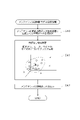
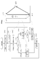
- FIG. 1 is an explanatory diagram showing a configuration of an information processing apparatus.
- the overhead crane 100 is a device for transporting a heavy object by moving on a traveling rail installed in a factory according to an operation of an operator. The structure will be described later.
- the overhead crane 100 is connected to the information processing apparatus 200 via the wireless LAN 20.
- the information processing device 200 is constructed by a server as hardware, and various information is acquired and stored in the information processing device 200 while the overhead crane 100 is in operation.
- the information processing apparatus 200 functions to analyze such information and control the operation of the overhead crane 100.
- a computer 30 as a terminal is connected to the wireless LAN 20.
- the computer 30 is used for viewing data and analysis results stored in the information processing apparatus 200, for instructing the operation of the overhead crane 100, and the like.
- a tablet, a smartphone, or the like may be used as a terminal.
- the information processing device 200 is connected to the learning model generation system 500 via the Internet.
- the learning model generation system 500 is constructed by a server connected to the Internet as hardware, and plays a role of generating a learning model of machine learning used by the information processing apparatus 200 when realizing various functions.
- the learning model generation system 500 is constructed as a system separate from the information processing apparatus 200 in this way, but both may be installed in the same facility, or the learning model generation system 500 may be installed. , May be incorporated into the information processing apparatus 200 and configured as an integrated system. On the contrary, a part or all of various functions of the information processing apparatus 200 described later may be provided by an external server connected via the Internet. In this sense, the information processing apparatus 200 is not necessarily limited to a system composed of only one factory premises.
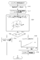
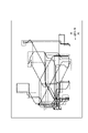
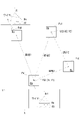
- FIG. 2 is an explanatory diagram showing the structure of the overhead crane 100.
- the overhead crane 100 is provided with a hoist 120, which is a lifting device for transporting a suspended load.
- the hoist 120 can raise / lower the suspended load by hoisting and lowering the wire 121 to which the hook 122 for hooking the suspended load is attached to the tip of the hoist 120.
- Operations such as winding / unwinding the wire 121 and moving the hoist 120 in the hoist 120 can be performed by the controller 130 connected by the cable 131.
- An enlarged view of the controller 130 is shown in the lower left of the figure.
- the controller 130 has a push button 132 for turning the power on and off, a push button 133 for winding / unwinding the wire 121, and four push buttons 134 for moving in four directions of north, south, east, and west.
- the controller 130 is not limited to such a method.
- the controller 130 instead of the four push buttons 134, the controller itself may be rotated around the central axis of the cylindrical housing so that the moving direction of the hoist 120 can be instructed.
- a wireless type controller 130 may be used instead of the wired type controller connected by the cable 131.
- a camera 124 is attached to the hoist 120.
- the camera 124 can capture a moving image and is fixed downward so that it can capture a vertically downward image.
- a still camera that captures a still image may be used.
- the captured image data is transmitted to the information processing apparatus 200 via the wireless LAN 20 described with reference to FIG.
- a laser radar 125 is also attached to the hoist 120.
- the laser radar 125 is a device that irradiates a laser from the main body and measures the distance to the person or object based on the time until it hits the surrounding person or object and is reflected. By scanning the laser in a certain range, the shape and distance of surrounding people and objects can be obtained in the form of a three-dimensional point cloud.
- the laser radar 125 is mounted downward so as to obtain a three-dimensional point cloud below the hoist 120. The obtained three-dimensional point cloud is transmitted to the information processing apparatus 200 via the wireless LAN 20.
- a display 123 is attached to the hoist 120 downward.
- a liquid crystal display is used in this embodiment, but an organic EL, LED or other display can also be used.
- the display 123 displays the moving direction of the hoist 120 and other useful information during the operation of the crane to the operator and the like.
- the hoist 120 may be further equipped with a camera capable of photographing the display contents of the display 123. For example, by mounting the camera 124 that shoots downwards so that the orientation of the camera 124 can be changed, the camera for shooting the display 123 may also be used. By providing a camera for photographing the display 123 in this way, it is possible to determine the display content and the abnormality of the display state from the image, prevent the display 123 from failing, and promptly take the failure. Correspondence becomes possible.
- traveling rails 101 and 102 are laid parallel and horizontally near the ceiling of the building.
- Saddles 111 and 112 are mounted on the traveling rails 101 and 102 so that they can travel as shown by the arrow a by the power of the motor.
- a crane girder 110 is fixed to the saddles 111 and 112 so as to straddle the saddles 111 and 112.
- the crane girder 110 is provided horizontally and in a direction orthogonal to the traveling rails 101 and 102.
- the crane girder 110 can also move as a unit.
- the hoist 120 is attached to the crane girder 110 so that it can be moved in the direction of arrow b along the crane girder 110 by a motor. Therefore, the combination of the movement of the crane girder 110 in the direction of arrow a and the movement of the hoist 120 in the direction of arrow b makes it possible for the hoist 120 to arbitrarily move in the space between the traveling rails 101 and 102.
- a mechanism for detecting the position of the hoist 120 is provided.
- a marker 103 for detecting the position is drawn on the traveling rail 102.
- a marker 114 for position detection is drawn on the crane girder 110.
- the hoist 120 is moving, the movement amount of the hoist 120 and the position of the hoist 120 in the b direction can be detected by optically reading the marker 114 by the sensor 127 fixed to the hoist 120.
- the position coordinates are transmitted to the information processing apparatus 200 via the wireless LAN 20.
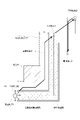
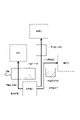
- FIG. 3 is an explanatory diagram showing the configuration of the position detection mechanism.
- the mechanism for detecting the position of the saddle 112 in the a direction on the traveling rail 102, that is, the X coordinate in FIG. 2 is shown.
- the right direction is the plus direction of the X coordinate and the left direction is the minus direction.
- the origin can be set at any location.
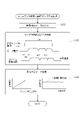
- the marker 103 described with reference to FIG. 2 is drawn on the traveling rail 120.
- this marker 103 includes a position detection marker 103a and a coordinate detection marker 103b.
- the position detection marker 103a is a drawing of white and black regions alternately. The width wb of the black region is constant. Further, the width ww of the white area is also constant. Both wb and ww may have the same width or may be different.
- the position detection marker 103a is drawn over the entire traveling rail 120. In this embodiment, a tape on which the pattern shown in the figure is drawn is prepared in advance, and the tape is attached to the traveling rail 120.
- the coordinate detection marker 103b is a short marker drawn at an appropriate position on the traveling rail 120.
- the coordinate detection marker 103b is formed of white and black regions, but the number and width thereof are different for each provided location. That is, one pattern composed of the number and width of white and black represents a specific position of the traveling rail 120.
- the position detection mechanism includes optical sensors 113a and 113b for detecting the position detection marker 103a and optical sensors 113c for detecting the coordinate detection marker 103b.
- the optical sensors 113a and 113b are installed so as to be out of phase with respect to the traveling direction. Therefore, when moving to the right side, the optical sensor 113a detects the black and white patterns, and then the optical sensor 113b detects the black and white patterns with a slight delay. On the contrary, when moving to the left side, the optical sensor 113b detects the black and white patterns, and then the optical sensor 113a detects the black and white patterns with a slight delay. In this way, it is possible to determine whether the sensor is moving to the right side or the left side based on the time difference between the detections by the optical sensors 113a and 113b.
- the method of specifying the X coordinate of the hoist 120 by the position detection mechanism is as follows.
- Nb ⁇ wb + Nw ⁇ ww may be added to the conventional coordinate values based on the number of black detections Nb and the number of white detections Nw by the optical sensor 113a or the optical sensor 113b.
- Nb ⁇ wb + Nw ⁇ ww may be subtracted from the previous coordinate values.
- the output states of the two are (1) both the optical sensors 113a and 113b are black, and (2) the optical sensors 113a are black.
- the four light 113b, (3) the optical sensors 113a and 113b are both white, (4) the optical sensor 113a is white, and the optical 113b is black are periodically output in the section of wb + ww. Therefore, by using these four outputs, it is possible to specify the position with a resolution higher than the width wb of the black region and the width ww of the white region.
- the pattern is specified based on the number and width of the black and white areas, and the X coordinate value is specified by referring to the pattern information stored in advance. can do. Since the coordinate value calculated by the position detection marker 103a may include an error, when the coordinate value is specified by the coordinate detection marker 103b, it is calculated by the position detection marker 103a with this value. Correct the coordinate values. By doing so, the accuracy of position detection can be improved.
- the detection of the position information may be performed by another method.
- the position coordinates of the camera 124 are obtained by preparing the positions of the equipment and the like in the facility as a database in advance, analyzing the lower image taken by the camera 124, and obtaining the relative positional relationship with the equipment and the like.
- a method of detecting the position coordinates of the hoist 120 may be adopted.
- the equipment instead of the equipment, a marker having a predetermined shape that is easy to detect may be used.
- the laser radar 125 may measure the distance to the wall around the facility, thereby detecting the position with respect to the wall, and thus the position coordinates of the hoist 120.
- a laser ranging device for measuring the distance to the surroundings may be separately attached to the hoist 120. If radio waves can be received well in the facility, it is also useful to use GPS together.
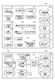
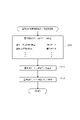
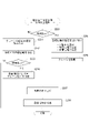
- FIG. 4 is an explanatory diagram showing the configuration of the information processing apparatus 200 and the learning model generation system 500.
- the information processing device 200 and the learning model generation system 500 are each composed of a computer equipped with a CPU and a memory, particularly a server, as hardware, and each functional unit shown in the figure is constructed by software. Some or all of these functional parts may be built in terms of hardware. Hereinafter, each functional unit will be described.
- the operation record database 201 is a database that stores various information during operation of the overhead crane 100.
- the data to be stored includes the position coordinates of the hoist 120, the operation data of the controller, the work data such as the type of suspended load and the transportation schedule, and the like.
- Position coordinates, operation data, etc. are stored in time series by associating each data with the obtained time information.
- the position coordinates and the operation data are stored separately.
- a method of sequentially storing each time, position coordinates, and operation data as a set of data may be adopted. This method has the advantage that the relationship between the position coordinates and the operation can be easily collated.
- operation record data For example, during the lifting and lowering operations of the suspended load, the same position coordinates are repeatedly stored even though the hoist 120 does not move. Therefore, a wasteful amount of data is likely to occur.
- the data storage format may be selected by comprehensively considering such advantages and disadvantages.
- the data stored in the operation record database 201 may be collectively referred to as “operation record data”.
- the 3D point cloud database 202 stores the data of the 3D point cloud obtained by the laser radar 125.
- the three-dimensional point cloud data is repeatedly acquired at predetermined time intervals, and is stored in the three-dimensional point cloud database 202 in association with the acquired times.
- the image database 203 stores the image data obtained by the camera 124.
- the image data is a moving image.
- Image data is also stored in a form in which each scene is associated with the time.
- the incident database 204 stores the time and position coordinates when an abnormality is detected in the facility where the crane is installed, and the information for specifying the three-dimensional point cloud data and the image data before and after the abnormality.
- the crane of this embodiment has a function of monitoring the inside of the facility in an unmanned state in addition to the normal operation of transporting the suspended load. It also has a function to determine whether or not an accident has occurred during normal operation.
- the "abnormality" stored in the incident database 204 means anomalies found by surveillance, specifically fires and suspicious persons, and also accidents.
- the case database 204 stores information for specifying the three-dimensional point cloud data and the image data for a predetermined period before and after the occurrence of the abnormality.
- the basic operation database 205 stores image data representing the basic operation that the operator should perform while the crane is in operation. This data can be used to determine whether or not the worker has performed these basic operations during operation. It can also be used to teach the worker the basic operation that should be performed. In this embodiment, in order to use the former for the judgment, a moving image taken from the top to the bottom is used as the basic operation as in the camera 124. As data for teaching the operator, an image of a person taken from the front may be prepared. Each image data is stored in association with the name of the basic operation to be performed by the operator.
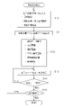
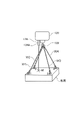
- the crane movement control unit 210 functions to control the movement of the crane. In the normal operating state of transporting a suspended load, the crane is mainly moved by an operator by operating the controller 130 (see FIG. 1). However, in this embodiment, in addition to this, the crane can move unmanned in the facility in a predetermined scan pattern and monitor the presence or absence of an abnormality. The crane movement control unit 210 controls the movement of the crane for this monitoring. As a scan pattern, for example, in FIG. 2, with the hoist 120 located at the end of the crane girder 110, the crane is driven in the a direction from one end to the other end of the traveling rails 101 and 102 in FIG. 2 for main scanning.
- a scan pattern for example, in FIG. 2, with the hoist 120 located at the end of the crane girder 110, the crane is driven in the a direction from one end to the other end of the traveling rails 101 and 102 in FIG. 2 for main scanning.
- a sub-scanning in which the position of the hoist 120 is shifted in the b direction is performed, and the main scanning is repeated to obtain a zigzag pattern.
- the main scan may be performed in the b direction and the sub scan may be performed in the a direction.
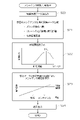
- These scans can be used not only for surveillance, but also for obtaining images of the entire floor of the facility where the crane is installed. That is, in the above-mentioned scan pattern, the images taken by the camera 124 are combined.
- Various well-known techniques can be applied to a method of synthesizing a plurality of images while aligning them with each other. In addition to fixed objects such as equipment and obstacles, there are also people in the facility, so when synthesizing images, you may select and combine parts that do not show people. By using the images obtained by scanning at different time zones, it is possible to obtain an image that can sufficiently represent the floor surface even if the image showing a person is excluded.
- the position detection unit 211 detects the position coordinates of the hoist 120 while the crane is in operation.
- the detection method is as described with reference to FIG.
- the position detection unit 211 receives the data transmitted from the overhead crane 100, and obtains the position coordinates based on the data.
- the obtained position coordinates are stored in the operation record database 201.
- the position coordinates are detected at regular time intervals.
- the position detection unit 211 since the crane moves relatively linearly, for example, it is not so necessary to detect the position coordinates in detail while moving at a constant speed. Therefore, the position detection unit 211 temporarily accumulates the position coordinates for a certain period of time, omits the acquired data for the section determined to be moving linearly at a substantially constant speed, and operates the operation record database. It may be stored in 201. By doing so, it is possible to suppress the amount of data of the position coordinates.
- the data acquisition unit 212 functions to acquire various data from the overhead crane 100.
- the acquired data includes image data taken by the camera 124, three-dimensional point cloud data obtained by the laser radar 125, operations on the controller 130, and the like.
- the acquired data is stored in the operation record database 201.
- the maintenance time determination unit 220 determines whether or not maintenance of the crane is necessary and the maintenance time based on the operation record data stored in the operation record database 201. When machine learning is used for these determinations, the maintenance time determination unit 220 holds a learning model generated by the learning model generation system 500 and makes a determination using the learning model. Examples of the maintenance determination target include a motor for moving the hoist 120, a winding / unwinding motor, a wire 121, a controller 130, and the like.
- the basic operation determination unit 221 determines whether or not the worker has performed a predetermined basic operation while the crane is in operation. In this embodiment, the determination is made based on the comparison between the image data taken by the camera 124 and the basic operation database 205. From the three-dimensional point cloud obtained by the laser radar 125, only the point cloud of a person may be extracted, and based on this, it may be determined whether or not the basic operation is performed.
- the comparison between the image data or the three-dimensional point cloud data and the basic operation database 205 can be performed by pattern matching, but it is more effective to use machine learning. When machine learning is used, the basic motion determination unit 221 holds a learning model generated by the learning model generation system 500, and makes a judgment using the learning model.
- the statistical processing unit 222 performs various statistical processing related to the operation of the crane.
- Statistical processing includes, for example, calculation of the operating time of the information processing device, calculation of the total transportation time of the suspended load, the average transportation time, the total moving distance, the average moving distance, etc., the average moving speed of the hanging device, and the raising and lowering of the suspended load.
- the total time required for the operation, the calculation of the average value, and the total number of operations of the controller can be mentioned. Not only daily statistical processing but also weekly or monthly statistical processing may be performed, or daily, weekly, monthly comparison and the like may be performed.
- the results of statistical processing can be used for determination of maintenance time and operation diagnosis.
- the result of statistical processing may also be stored in the operation record database 201.
- the risk assessment unit 223 evaluates the presence or absence of danger and its degree during and after the crane is in operation.
- a series of operations for transporting the suspended load such as attaching a wire to the suspended load, lifting, starting transportation, during transportation, lowering the suspended load, and removing the wire, are divided into scenes, and each scene is described. It was decided to evaluate the danger. Danger assessment is performed based on the positional relationship between the suspended load and people, equipment, etc.
- the risk assessment unit 223 holds a learning model generated by the learning model generation system 500 and makes a judgment using it.
- the accident judgment unit 224 determines whether or not an accident has occurred while the crane is in operation. In this embodiment, it is performed based on the positional relationship between the suspended load and a person, equipment, etc., the posture of the person, and the like.
- the risk assessment unit 223 holds a learning model generated by the learning model generation system 500 and makes a determination using the learning model.
- the security operation unit 225 monitors the inside of the equipment unattended by a crane, and when an abnormality is found, it functions to deal with it. Abnormalities include fire and the discovery of suspicious persons. Countermeasures include changing the crane scan pattern and reporting.
- the operation diagnosis unit 230 has a function of diagnosing the operation of the crane after the crane is operated.
- the contents of the diagnosis include the presence or absence of danger, its degree, and operating efficiency.
- the transport sequence optimization unit 231 provides the result of optimizing the transport order of suspended loads by a crane. When transporting a plurality of suspended loads, depending on the order, the distance traveled by the crane with an empty load becomes long, which causes waste. The transport sequence optimization unit 231 optimizes the transport order of suspended loads so that the travel distance and travel distance of an empty load are shortened.
- the optimum route setting unit 233 provides an optimum route that optimizes the transport route of the suspended load by the crane. For example, when transporting a suspended load from point A to point B, the straight line connecting both points is the route with the shortest travel distance, that is, the optimum route. In this embodiment, the optimum route is obtained in this way based on various constraint conditions.
- the layout optimization unit 234 optimizes the layout of equipment and obstacles in the facility where the crane is installed. For example, the shortest transportation route for suspended loads is a straight route connecting the departure and arrival points.
- the layout optimization unit 234 provides, for example, a layout in which equipment or obstacles on the route are moved so as to realize this. Also, consider changing the landing site of the suspended load.
- the display control unit 232 displays the outputs of the various functions described above on the screen of the computer 30 connected to the information processing device 200. It may be displayed on the display 123 attached to the crane. The displayed contents differ depending on each function.
- the image providing unit 235 at the time of abnormality provides image data for a predetermined period before and after the time of occurrence, and three-dimensional point cloud data.
- the storage location of the image data or the like corresponding to the designated abnormality is specified with reference to the case database 204, and this is read from the image database 203 or the three-dimensional point cloud database 202.
- the provision can be a method of outputting it to a recording medium or the like as a series of moving image data.
- the ground cutting safety support unit 250 functions to support the improvement of safety at the moment when the suspended load lifted by the crane leaves the floor surface, that is, at the moment of ground cutting.
- the crane accurately lifts the center of gravity of the suspended load, the suspended load rises with almost no shaking as the crane is hoisted, but if the lifting position deviates even a little from the center of gravity, it is suspended at the moment of ground cutting.
- the load may sway back and forth and left and right. As a result, when lifting a heavy object, an accident such as a worker colliding with the suspended load may occur.
- the ground cutting safety support unit 250 memorizes the position of the crane when the suspended load is placed on the floor, and when the suspended load is lifted again, the position is memorized and accurately reproduced. To do. By doing so, the crane can accurately lift the center of gravity of the suspended load.
- the ground cutting safety support unit 250 has a function of managing a memorized position, various functions for accurately reproducing the position of the center of gravity, and a function of improving convenience such as registration or reproduction of a position. And so on. Of course, some of these functions may be omitted.
- the transmission / reception unit 240 exchanges data with the overhead crane 100, the computer 30, the learning model generation system 500, etc. via the wireless LAN 20 and the Internet.
- the transmission / reception unit 240 also provides a function as an input unit that receives commands from the computer 30 to the information processing apparatus 200 in setting the optimum route, the optimum sequence, the optimum layout, and the like.
- the learning model generation system 500 is a system for generating a learning model used in various functions provided by the information processing apparatus 200 by machine learning and providing the information processing apparatus 200 with the learning model.
- the system is constructed as a separate system from the information processing apparatus 200, but it may be constructed by incorporating it into the information processing apparatus 200.
- a learning model unique to the information processing apparatus 200 will be described below, but the learning model generation system 500 is a system for generating a general-purpose learning model common to a plurality of cranes. You can also do it.
- the operation record database 501, the three-dimensional point cloud database 502, and the image database 503 correspond to the operation record database 201, the three-dimensional point cloud database 202, and the image database 203 in the information processing apparatus 200, respectively.
- each database of the information processing apparatus 200 is appropriately copied to the learning model generation system 500 and updated. By doing so, if machine learning is repeated, re-learning that reflects the operating results of the crane can be performed, and the accuracy of the learning model can be further improved.
- the contents of the operation record database 501, the three-dimensional point cloud database 502, and the image database 503 may be different from each database in the information processing apparatus 200 in consideration of the generation of the learning model. For example, data unnecessary for machine learning described below may be omitted. Further, the determination result made by using the learning model in the information processing apparatus 200 may be stored as one of the operation record data.
- the transmission / reception unit 540 exchanges data with the information processing device 200 via the Internet.
- the data to be exchanged includes operation record data and other data stored in each database, a learning model, and the like.
- the learning data generation unit 510 generates machine learning data based on the data stored in the operation record database 501, the three-dimensional point cloud database 502, and the image database 503. For example, there is a case where data of the time from the start of the operation to the start of the movement of the crane is generated based on the time when the controller is operated and the position information of the hoist 120. In addition, various data will be generated according to the content of machine learning.
- the maintenance time determination model generation unit 521 generates a learning model for determining the maintenance time of the crane.
- Examples of the maintenance determination target include a motor for moving the hoist 120, a winding / unwinding motor, a wire 121, a controller 130, and the like.
- the maintenance time determination model generation unit 521 may generate a learning model for each of these objects.
- the danger level judgment model generation unit 522 generates a learning model for evaluating the presence or absence of danger and its degree regarding the operating status of the crane.
- teacher data showing the presence or absence of danger and its degree are prepared for various situations, and supervised machine learning based on this is used. Other methods may be used.
- the accident judgment model generation unit 523 generates a learning model for judging whether or not an accident has occurred while the crane is in operation.
- supervised machine learning is used. Other methods may be used.
- the learning model generation unit 520 for determining the basic operation generates a learning model for determining whether or not the worker has performed a predetermined basic operation while the crane is in operation.
- image data when the original basic operation is performed and image data when these basic operations are not performed are prepared in the basic operation database 505, and these are used as teacher data for machine learning classification. I made it. Similar to the camera 124, the image of the basic operation database 505 is based on a moving image taken from the top to the bottom, which is made into a series of still images for each frame, and then from each still image data. Only the target human part was cut out.
- the information processing device 200 and the learning model generation system 500 provide various functions described later by the above-mentioned functional units.
- the configuration of the functional unit described with reference to FIG. 4 is merely an example, and functional units other than these may be prepared, the functional unit shown here may be divided into a plurality of functional units, or a plurality of functional units may be provided. It may be integrated.
- FIG. 5 is a flowchart of the trajectory display process. This is a process mainly performed by the position detection unit 211 and the display control unit 232 shown in FIG. 4 using the operation record data stored in the operation record database 201, and is executed by the CPU of the information processing apparatus 200 in terms of hardware. Is.
- the information processing apparatus 200 inputs the designation of the date and time to be displayed (step S10). This designation can be made from a terminal such as a computer 30.
- a date is specified, the movement trajectory for the corresponding day is displayed.
- the movement trajectory of the corresponding period is displayed. This is useful when you want to display the movement trajectory of a specific time zone in a day. When multiple dates and times are specified, the movement trajectory of the corresponding day is displayed. This is useful when you want to compare these movement trajectories.
- Various other modes may be prepared for specifying the date and time.
- the information processing apparatus 200 reads the corresponding operation record data and image data (step S11). Then, statistical data is calculated based on these (step S12).
- the traveling distance which is the traveling distance in the traveling rails 101 and 102 directions, the traversing distance which is the traveling distance in the crane girder 110 direction, the number of times the push button of the controller is operated, the carrying distance of the suspended load, the operating time of the crane, etc. was to be sought. Other statistical processing may be performed.
- the information processing apparatus 200 uses these data to display the movement locus according to the display mode (step S13).
- Examples of the display mode include a mode in which only the movement locus is displayed, a mode in which image data is displayed together with the movement locus, and the like.
- the display mode change instruction is given (step S14)
- the information processing apparatus 200 displays the movement locus again according to the instruction (step S13).
- the change of the date and time to be displayed is instructed (step S15)
- the processing after step S10 is executed again. In other cases, that is, when the end of the display is instructed, the locus display process ends.
- the information processing apparatus 200 displays the movement locus at the designated date and time.
- FIG. 6 is an explanatory diagram showing an example (1) of the locus display screen.
- the target display time setting (d11) is displayed on the screen D1 displayed on the computer 30, and the corresponding movement locus (d14) is displayed.
- the movement locus is a straight line or a curve connecting the position information of the time series in which the crane moves in the facility.
- the broken line shows the movement locus with an empty load
- the solid line shows the movement locus with the suspended load being carried. In this way, by changing the display mode between empty and transporting, it is possible to easily visually grasp the operation record of the crane.
- a button d12 for instructing the display of statistical data is prepared.
- statistical data d17 such as mileage is displayed.
- the movement locus can be displayed as a moving image.
- the moving image may be, for example, a mode in which a symbol representing a crane moves on a moving locus. Further, the movement locus may be drawn according to the movement of the crane.
- FIG. 7 is an explanatory diagram showing an example (2) of the locus display screen.
- a movement locus is displayed in the area d21, and the symbol d23 representing the crane moves along the movement locus. Further, the image corresponding to the position of the symbol d23 is displayed in the area d22. According to this display mode, the moving state of the crane can be easily confirmed by an image.
- the moving image display in which the symbol d23 is moved when one point d23 on the movement locus is clicked in the area d21, the corresponding still image may be displayed in the area d22.
- the display of the movement locus can take various modes other than those shown in FIGS. 6 and 7.
- the crane user can visually grasp the operation record of the crane.
- the movement locus in association with the operation or the image, it becomes easy to confirm the situation including whether or not the crane is properly operated.
- the result of statistical processing it is possible to objectively grasp the operation results.
- FIG. 8 is a flowchart of the maintenance time determination process. This is a process mainly performed by the maintenance time determination unit 220 shown in FIG. 4 using the operation record data stored in the operation record database 201, and is a process executed by the CPU of the information processing apparatus 200 in terms of hardware.
- the information processing apparatus 200 reads the operation record data (step S20) and generates various cumulative data since the previous maintenance (step S21). Maintenance may include regular inspections. The reason for setting it after maintenance is that it is considered that the troubles of the crane have been solved by the maintenance.
- the information processing apparatus 200 reads a determination threshold value for determining the necessity of maintenance (step S22).
- the method of setting the judgment threshold is shown in the figure. For example, consider the case of determining the maintenance time of the push button of the controller.
- the distribution as shown in the figure can be obtained by drawing the past results by taking the number of operations on the horizontal axis and the number of failures on the vertical axis.
- the "number of cases" does not mean the number of times a failure has occurred in one controller. In the past results, it means that the number of failures occurred in the Nth operation count is n, and the number of failures occurred in the Mth operation is m.
- the determination threshold value may be set by "mean value-coefficient x standard deviation". A coefficient of 3 to 5 can be used.
- the determination threshold value is a value preset by such a method.
- the determination threshold value may be set for each target for determining the maintenance time, such as a controller, a motor, and a display.
- the above method is merely an example of setting the determination threshold value, and the determination threshold value can be arbitrarily set.
- the battery consumption of the controller may also be a target of determination.
- the information processing apparatus 200 predicts the maintenance time by comparing the cumulative data with the determination threshold value (step S23). If the cumulative data has already exceeded the determination threshold, it will be promptly determined that maintenance is required.
- the maintenance time can be predicted by various methods when the cumulative data does not exceed the determination threshold value. An example is shown in the figure. The horizontal axis represents the elapsed time since the last maintenance, and the vertical axis represents the number of operations. The line connecting the origin, the current elapsed time, and the number of operations is extended to obtain the time for the number of operations to reach the determination threshold. By doing so, it is possible to predict when the threshold value will be reached and the maintenance time can be predicted if the number of operations increases, with the same tendency as until now.
- the information processing apparatus 200 performs the above-mentioned determination process for each maintenance determination target. The judgment method may be changed for each judgment target. Further, a method other than the above may be used for predicting the maintenance time.
- the information processing apparatus 200 outputs the result obtained in this way (step S24), and ends the maintenance time determination process.
- a screen display on the computer 30, an e-mail transmission to the person in charge, or the like can be taken.
- the display on the display 123 of the crane or other alarm may be given.
- FIG. 9 is a flowchart of the data generation process for determining the maintenance time. This is a process to generate data for machine learning based on the data accumulated as operation results. This is a process mainly performed by the learning data generation unit 510 shown in FIG. 4, and is a process executed by the CPU of the learning model generation system 500 in terms of hardware.
- the learning model generation system 500 reads the operation record data from the operation record database 501 (step S30) and generates the motor operation status data (step S31). The contents of data generation are shown in the figure.
- the graph above shows the on / off state of the pushbuttons on the controller.
- pushbuttons There are multiple pushbuttons, but only one of them is shown here as an example.
- the crane moves during the top with the pushbutton turned on.
- the current of the motor is shown in the middle stage. After the push button is turned on, current starts to flow in the motor after a lapse of time dt. After that, the current flows until the push button is turned off, with a slight change due to noise.
- the motor current suddenly drops during the time ti0 and ti1 within the period of the top in which the push button is turned on.
- the lower part shows the change in the moving speed of the crane.
- the crane moves according to the change in the current of the motor. Where the motor current drops, the moving speed of the crane also drops. From the average speed of the crane, the average speed of the crane can be obtained.
- the data generation process step S31
- various other data may be generated depending on the content of machine learning.
- the learning model generation system 500 generates data on the suspended load status (step S32).
- the contents of data generation are shown in the figure.
- the left side is the relationship between the hoisting amount of the crane and the suspended load height.
- the height of the suspended load increases proportionally. If the wire 121 for lifting the suspended load becomes loose, the graph tends to be stretched at the time of lifting, so that the slope of this graph may become gentle or deviate from the straight line.
- the data generation process as data for determining the maintenance time of the wire 121, data representing an increase in the suspended load with respect to the crane hoisting amount, for example, the inclination of the illustrated graph is calculated. Will be done.
- the right side of the figure shows the change in the height of the suspended load during transportation.
- the height of the suspended load is maintained at a substantially constant height while vibrating.
- the elastic force decreases, so that the frequency of this vibration decreases and the amplitude tends to increase.
- the amplitude and frequency of the vibration of the suspended load height during crane transportation are calculated as data for determining the maintenance time of the wire 121.
- various other data may be generated depending on the content of machine learning. For example, a camera may be attached to a worker's helmet, a suspended load may be photographed, and the situation may be image-analyzed to generate data for machine learning.
- Data such as the height and vibration of the suspended load may be acquired, or the angle of the wire when suspending the load and its change may be acquired. Further, regarding the display device, the presence / absence and quantity of display defects, the presence / absence and degree of display flicker, and the like can be quantified as data for machine learning based on the image taken by the display device.
- FIG. 10 is a flowchart of the maintenance time determination model generation process. This is a process mainly performed by the maintenance time determination model generation unit 521 shown in FIG. 4, and is a process executed by the CPU of the learning model generation system 500 in terms of hardware. In this example, unsupervised machine learning is used.
- the learning model generation system 500 reads the learning data generated in the maintenance time determination data generation process (FIG. 9) (step S40).
- a cluster of learning data is generated for each of the push button, the motor, and the wire, which are the targets for determining the maintenance time.
- the learning data related to the operation of the push button includes the time interval top when the push button is turned on, the time td until the motor current starts up, the time ti0, ti1 when the motor current drops, and the average of the cranes. Speed etc. can be mentioned.
- the crane is in operation, most of it is considered to be in a normal state that does not require maintenance, so the area where the training data is concentrated is considered to represent a normal state.
- the data outside the concentrated area is in a state where an abnormality is occurring, that is, a state requiring maintenance. Therefore, if a learning model for recognizing a region considered to be normal as a cluster is generated based on the learning data, it can be utilized for the necessity of maintenance.
- the image of the process is shown in the figure.
- the data indicated by white circles represent the learning data in the normal state.
- the data represented by x represents the learning data in the abnormal state.
- Creating a cluster corresponds to the process of generating a learning model for determining the area of the broken line in the figure.
- the cluster is represented by, for example, its central CG and the distance R.
- the learning data to be determined exceeds the distance R from the central CG, it is determined that it is outside the cluster, and it is determined that maintenance is required.
- the learning data is represented in a three-dimensional space, but the dimension of this space varies depending on the type and number of learning data.
- the learning model generation system 500 outputs the learning model thus generated, that is, the maintenance time determination model (step S42), and ends the maintenance time determination model generation process.
- FIG. 11 is a flowchart of the maintenance time determination process as a modification. This is a process mainly performed by the maintenance time determination unit 220 shown in FIG. 4 using the operation record data stored in the operation record database 201, and is a process executed by the CPU of the information processing apparatus 200 in terms of hardware.
- the information processing apparatus 200 reads the operation record data (step S50) and executes the maintenance time determination process data generation process (step S51). The content of this processing is as described with reference to FIG. It executes the same processing as that performed when generating the learning model. Then, the information processing apparatus 200 calculates the distance DC from the cluster center by using the maintenance time determination model generated in advance (step S52). The image is shown in the figure.
- the learning model gives the central CG of the cluster whose operation performance is judged to be "normal" and its distance R. Therefore, the distance DC is calculated in order to determine whether or not the operation record exists in the cluster.
- step S53 When the calculated distance DC is larger than the distance R to the boundary of the cluster (step S53), it means that the operation record is out of the normal state. Therefore, the information processing apparatus 200 determines that maintenance is necessary and notifies that fact (step S54). Notification can be made in various ways.
- step S53 when the distance DC is less than or equal to the distance R (step S53), it is determined that maintenance is not yet required at this time. Therefore, the maintenance time is predicted based on the current situation (step S55). As shown in the figure, by extending the elapsed time since the previous maintenance and the current distance DC, the time when this reaches the distance R is obtained, and this is set as the maintenance time. The information processing apparatus 200 notifies the maintenance time predicted in this way (step S56). In addition to this, various methods can be adopted as the maintenance time prediction method and the notification method.
- FIG. 12 is a flowchart of the risk assessment process. It is a process mainly performed by the risk evaluation unit 223 and the basic operation determination unit 221 shown in FIG. 4, and is a process executed by the CPU of the information processing apparatus 200 in terms of hardware. This process is a process executed after the operation of the crane to determine the presence or absence of danger and its degree based on the operation record data, the three-dimensional point cloud data, and the image data. Sensors may be attached to the worker's helmet, work gloves, work clothes, etc., or a characteristic marker may be attached to facilitate recognition by image analysis, making it easier to identify the worker's posture. .. In the following description, the "danger level" means an index for expressing the presence or absence of danger and its degree.
- the information processing apparatus 200 determines which transportation scene the operation record for evaluating the presence or absence of danger corresponds to (step S60). In this embodiment, it is divided into six scenes before, during lifting, starting of transportation, during transportation, during suspension, and after suspension. The lifting may be subdivided into, and after the ground cutting.
- status data indicating which of these situations corresponds to is stored as the operation record data, it can be easily determined based on the status data. Even when the status data is not used, it is possible to make a judgment based on the position information of the crane, the hoisting / unwinding information, the information on whether or not the crane is carrying the suspended load, and the like.
- the state after the crane moves with an empty load and stops is determined to be before the suspended load is lifted.
- the state of being hoisted is determined to be the hoisting of the suspended load.
- the winding is completed, it is judged that the transportation has started.
- the crane starts moving it is judged to be in transit.
- the crane stops and starts unwinding it is judged that the suspended load is being lowered.
- the unwinding it is judged that the suspended load has been lowered.
- the scene by various other methods.
- the presence or absence of a suspended load may be analyzed using image data or three-dimensional point cloud data to determine the transportation scene.
- the information processing apparatus 200 evaluates the presence or absence of danger and its degree by the following processing for each scene.
- the information processing apparatus 200 detects the shape of the suspended load, the position of the wire, the position of the crane, and the like (step S61). These detections can be performed by analyzing the three-dimensional point cloud data and the image data.
- the image data is planar and it is difficult to specify the distance from the camera 124 to the object, whereas the three-dimensional point cloud data is useful for this analysis because the position can be grasped three-dimensionally.
- a camera may be attached to the helmet of the worker, and the analysis result based on the image data of the luggage taken by the camera may be used. With this camera, it is possible to capture the angle of the wire when lifting the cargo, the elongation of the wire, the rotation of the cargo, the vibration, and the like.
- the information processing apparatus 200 calculates the degree of danger based on the positional relationship of the reference, and determines the reason (step S62).
- the positional relationship of the criteria for determining the degree of danger is set in advance for each transportation scene as shown below. For example, before lifting, the procedure up to attaching the wire to the suspended load is the target. So, for example, a) Was there a worker in a position where the situation around the suspended load could be confirmed before the work started? b) Is the hook hung in a safe position with respect to the center of gravity estimated from the shape of the suspended load? ; c) Was the worker in a position to inspect the wires?
- the positional relationship characteristic of each item can be used as the reference positional relationship. Further, not only the worker but also the position of the assistant who assists the worker may be taken into consideration around the suspended load. Further, not only the work of attaching the wire to the suspended load but also the basic operation such as whether the safety inspection such as the wearing condition of the helmet is performed before starting the work may be considered as a judgment factor of the degree of danger.
- FIG. 13 is an explanatory diagram showing an example of a scene before lifting. It can be seen that the operator is working with the controller at one end of the suspended load, and the operator is at the other end. A wire is hung on the suspended load.
- the image data or the three-dimensional point cloud data of this scene it is possible to grasp the positional relationship between the operator, the operator, the suspended load, the wire, and the like. Then, it can be determined whether or not the item b) is satisfied based on the positional relationship between the suspended load and the wire. Further, since it can be confirmed that the worker covers the suspended load, it is determined that the operator is inspecting the wire in item c). In this way, the above items can be determined by analyzing the image data and the three-dimensional point cloud data.
- the degree of risk for each item as an index. For items that must be performed to avoid danger, set the risk level to 100 (%), and for items with a low impact level, set the risk level to 50 (%).
- the degree of risk can be set arbitrarily, but for example, it may be set based on the probability that an accident will occur when the item is not performed, based on past results. Further, the degree of danger does not necessarily have to be expressed in%, but may be expressed in some score or the like.
- step S62 it is determined to what extent the above-mentioned reference positional relationship is satisfied based on the detected positional relationship and the like, and the degree of danger is determined. For example, when the risk level of item a) is set to the value A (%), the risk level is 0 (%) when the positional relationship corresponding to this item is satisfied, and A when the positional relationship corresponding to this item is not satisfied at all. Judged as (%). In the meantime, the degree of risk is calculated by A ⁇ coefficient according to the degree. Perform the same calculation for all items. Then, the overall risk level is calculated based on the average value or the maximum value of the obtained risk levels. In addition, the item with the highest risk in this calculation process has a large effect on the overall risk.
- the content of the item can be selected as the "reason" for the degree of risk.
- the work environment may be considered as another factor for determining the degree of risk. For example, if the work of attaching the wire to the suspended load is performed in a dark place, it may cause a mistake. Therefore, it may be considered whether or not the illuminance at the work site is equal to or higher than the standard.
- the following items can be mentioned. a) Did the wire-hung worker signal the operator of the crane that he was ready before lifting? ; b) Is there an operator near the wire? ; c) Are there any workers around the suspended load? ; And so on.
- the degree of risk and its reason can be calculated and selected in the same way as before lifting.
- the position and operation of an auxiliary worker who gives a signal or the like around the suspended load may be taken into consideration.
- it may be considered whether the luggage is kept horizontal during lifting, whether the luggage is moved in the horizontal direction at the time of ground cutting, the degree of vibration of the luggage, and the like.
- the hoisting speed of the crane when lifting the cargo may be considered. Since the hoisting speed has a predetermined recommended value or upper limit value, if it exceeds this, the risk becomes high. From this point of view, the risk level may be determined based on the hoisting speed.
- the information processing apparatus 200 outputs the risk level and the reason obtained in the above processing as a result (step S69), and ends the risk level evaluation process.
- the result output can take a mode of displaying the degree of danger, the reason, and the corresponding image data, as shown in FIG. The contents of this display will be described in detail later.
- the risk evaluation result may be added to and stored in the operation record data.
- the shape, positional relationship, etc. to be detected in step S61 are for determining the positional relationship of the above-mentioned reference. Therefore, the content to be detected may be determined based on the positional relationship of the reference before and during the lifting. The content to be detected in step S61 may be different depending on the transportation scene before and during the lifting.
- the risk assessment process has been described as being performed after the fact based on the operation record data, it may be performed in real time as much as possible while the crane is in operation. In this case, if the degree of danger exceeds a predetermined value, a notification may be made as a result output (step S69).
- the notification for example, a method of displaying a warning to the display unit 123 of the crane, a method of sounding an alarm sound at the site during operation, a method of notifying the administrator by e-mail or the like can be taken.
- step S60 Start of Transportation Next, a case where it is determined that the transportation scene is the start of transportation (step S60) will be described.
- the information processing apparatus 200 detects the positional relationship between the suspended load and the crane operator and surrounding obstacles, and detects whether or not the basic operation is performed (step S63). Then, the degree of danger is calculated according to the detection result, the reason is created (step S64), and the result is output (step S69).
- the basic operation is also detected (step S63). While the above-mentioned reference positional relationship means a relatively static positional relationship, the basic operation means the movement of the operator. Examples of the basic operation include the following items. a) Confirmation operation of the traveling direction of the suspended load; b) Signal before the start of transportation; And so on. In this embodiment, a plurality of characteristic postures such as a pointing posture among the basic movements are extracted in advance as a database, and the image data or the three-dimensional point cloud data to be judged are analyzed, and these characteristic postures are obtained. It was decided to determine whether or not a good posture was detected.
- the basic operation may vary from company to company with a crane.
- a customization function may be provided for the basic operation. That is, each company may be able to select the basic operation prepared in advance or add the basic operation prepared independently. By providing such a function, it is possible to realize an evaluation in accordance with the rules of each company.
- a support function for adding a unique basic operation may be added. For example, there is a function in which a worker demonstrates the basic movement while taking a picture with a camera to cut out a plurality of postures characteristic of the basic movement and register them in a database. The idea of basic operation is the same in other situations.
- step S60 a case where it is determined that the transportation scene is being transported.
- the information processing apparatus 200 detects the positional relationship between the suspended load and the crane operator and surrounding obstacles, the moving speed of the crane, and the like, and detects whether or not the basic operation is performed (step S65). Then, the degree of danger is calculated according to the detection result, the reason is created (step S66), and the result is output (step S69).
- the concept of these processes is basically the same as before and during lifting.
- the following items are listed as items for setting the positional relationship of the reference. a) Are there any people or obstacles near the suspended load? ; b) Is the suspended load swaying or tilting? ; c) Is the moving speed appropriate? ; And so on. Based on these, the positional relationship and the degree of danger of the reference can be set, and the degree of danger for each item can be calculated by the same method as described in step S62.
- the condition of the passage may be taken into consideration. For example, if foreign matter such as oil is attached to the passage, the operator may fall and the crane may be in a dangerous state. Therefore, the presence or absence of foreign matter on the passage may be analyzed based on the image taken by the camera, and the degree of danger may be calculated based on this.
- Examples of the basic operation during transportation include the following items. a) Confirmation operation of the traveling direction of the suspended load; b) Confirmation operation when changing the direction; And so on.
- the detection of the basic operation can be performed by the same method as described in steps S63 and S64.
- step S60 During hanging load descent: Next, a case where it is determined that the transportation scene is being lowered (step S60) will be described.
- the information processing apparatus 200 detects the positional relationship between the suspended load and the crane operator and surrounding obstacles, and whether or not basic operation is performed (step S67). Then, according to this detection result, the degree of danger is calculated, the reason is created (step S68), and the result is output (step S69).
- Examples of the basic operation during transportation include the following items. a) Safety confirmation operation of the landing place of the suspended load; b) Signal before winding; And so on.
- the detection of the basic operation can be performed by the same method as described in steps S63 and S64.
- step S60 After the suspended load is finally lowered Finally, the case where it is determined that the transportation scene is after the suspended load is lowered (step S60) will be described.
- the processing of the information processing apparatus 200 is the same as before and during lifting (steps S61, S62, S69).
- the following items are listed as items for setting the positional relationship of the reference. a) Is the hook securely removed from the suspended load? ; c) Is there a worker near the wire? ; And so on. That is, if the wire is wound up without disconnecting the wire after the suspended load is lowered, an unexpected accident may occur, and the presence or absence of these dangers is determined. Based on these, the positional relationship and the degree of danger of the reference can be set, and the degree of danger for each item can be calculated by the same method as described in step S62.
- the degree of danger and the reason thereof can be determined according to each transportation scene.
- the detection of the basic operation is omitted in the determination (steps S61 and S62) before, during, and after the suspended load is lifted. It does not mean that the basic movement does not exist in these situations, but it is considered that the positional relationship of the reference has a greater influence on the danger than the basic movement in these situations. Therefore, the basic operation may be detected and determined for these transportation situations as well as the others.
- FIG. 14 is a flowchart of the learning model generation process for basic operation determination. This is a process mainly performed by the learning model generation unit 520 for determining the basic operation shown in FIG. 4, and is a process executed by the CPU of the learning model generation system 500 in terms of hardware.
- the learning model generation system 500 reads the basic operation list and the learning data (step S70). These are the data stored in the basic operation database 505. An image of the data structure is shown in the figure. For example, a series of operation data is stored in association with this name for the basic operation of "checking the surroundings before winding down".
- the motion data is a set of a series of still images representing the basic motion. The same applies to "Signs before winding down" and other basic operations.
- the learning model generation system 500 generates a learning model for each basic operation (step S71). Since it is a learning model for determining whether or not the image data to be determined represents this basic operation, machine learning classification as a kind of supervised learning is performed.
- the basic operation database 505 may include data of operations different from the basic operations.
- the motion data for this basic motion is used as the teacher data for the "correct answer”
- the motion data for the other basic motions is used as the teacher data for the "error”. It may be used as data.
- the learning model generation system 500 stores the learning model thus generated in association with the basic operation list (step S72). By storing this learning model in the basic operation determination unit 221 of the information processing apparatus 200, it is possible to determine whether or not the basic operation has been performed by utilizing the learning model.
- FIG. 15 is a flowchart of the risk degree determination model generation process. This is a process mainly performed by the risk level determination model generation unit 522 shown in FIG. 4, and is a process executed by the CPU of the learning model generation system 500 in terms of hardware.
- the learning model generation system 500 reads the operation record data (step S80). Then, the learning model generation system 500 generates learning data according to the transportation scene (step S81). The transportation scene and the contents of the learning data are shown in the figure. Each is the same as the content described with reference to FIG.
- the learning model generation system 500 generates a learning model by machine learning according to the transportation scene (step S82), and stores the learning model in association with the transportation scene (step S83).
- various methods can be applied to machine learning, in this embodiment, supervised learning is performed.
- machine learning regression was applied to meet the purpose of calculating the degree of risk.
- the teacher data is obtained by adding a degree of risk to a large number of prepared learning data.
- the degree of risk may be set from 0 to 100% based on the actual results of past accidents. However, it is difficult to set the degree of danger in this way, so for each learning data, it is dangerous (100%), a little dangerous (50%), and not dangerous (0%). It may be evaluated in three stages of. Even if each learning data is evaluated in about three stages, the risk level can be obtained in the range of 0 to 100% by obtaining the risk level distribution for many learning data. It is also possible to generate a learning model that gives.
- the generated learning model is stored in the risk evaluation unit 223 of the information processing apparatus 200. Even when machine learning is applied, the risk assessment process is the same as described with reference to FIG. In steps S62, S64, S66, and S68, respectively, the degree of danger is obtained by using the learning model according to the transportation scene. When using a learning model, the logic is often unknown, so it may be difficult to select the reason. If the learning model is generated in a way that is easy for logic to pursue, such as a decision tree, it is possible to select it because of the explanation corresponding to the node that affected the risk result.
- the information processing apparatus 200 can determine the degree of danger and the reason for the operation of the crane.
- the operation of a crane is divided into various transportation situations, and it is difficult to set common criteria for all of them.
- the degree of danger is evaluated separately for each transportation scene, so that the degree of danger can be appropriately evaluated in each transportation scene.
- machine learning to the determination of whether or not the basic operation has been performed, the accuracy can be improved even when the machine learning is not applied to the determination of the degree of danger itself.
- various factors are involved in the evaluation of the degree of risk, it is possible to realize a more appropriate evaluation by applying machine learning.
- Optimal route setting function (1) Concept of optimal route setting: Conventionally, when transporting suspended loads with a crane, transportation efficiency has not been considered so much. However, when moving the suspended load from the point A to the point B, the route connecting the two points with a straight line is the shortest distance, and the efficiency is the highest. Therefore, the information processing apparatus 200 provides a function of setting an optimum route so that the transportation efficiency is high. In reality, it is necessary to avoid equipment and obstacles, so the optimum route is set in consideration of these constraints.
- the concept of optimal route setting is shown, and the processing thereof will be described.
- FIG. 16 is an explanatory diagram showing the concept of optimum route setting.
- the floor plan of the facility is shown schematically.
- the movement route for optimization is along the passage of the crane operator as shown by the thin solid line.
- the method of setting the optimization route for this route is shown.
- Constraint 1 is that it does not collide with equipment or obstacles in the facility. In the example in the figure, it is necessary to set a route that can avoid the hatched obstacle.
- the constraints may be set to be more stringent and to keep a predetermined distance from the equipment and obstacles.
- the constraint condition 2 is to move within a predetermined distance from the operator's passage.
- the position of the distance W from the boundary line of the passage is shown by a broken line.
- This range is the movable area of the crane.
- the constraint condition 3 is the regulation of the moving direction of the crane.
- the moving direction is determined according to the specifications of the crane, and in this embodiment, the crane can move in eight directions as shown in the figure. For a crane that can move only in four directions, north, south, east, and west, there are four directions. In such a crane, it is technically possible to move the crane diagonally by operating the buttons in two directions such as east and north at the same time, but it is a dangerous operation, so do not do it. Assuming.
- the optimum route is a route including diagonal movement from the suspension point 1 to the landing point 1 direction.
- the optimum route shown is only an example, and in this example, there are various other movement routes having the same distance.
- the operator may select one of these routes after presenting them to the operator, or select one in consideration of other evaluation criteria. May be good. Examples of the evaluation criteria in such a case include those in which the number of times the traveling direction is changed is small, those in which the distance from the obstacle is large, and the like.
- the optimum route can be obtained for the movement from the landing point 1 to the hanging point 2 and the movement from the hanging point 2 to the landing point 2.
- the linear path shown by the thick line is set as the optimum path with respect to the L-shaped movement path shown by the thin line.
- FIG. 17 is a flowchart of the optimum route setting process. This is a process mainly performed by the optimum route setting unit 233 shown in FIG. 4, and is a process executed by the CPU of the information processing apparatus 200 in terms of hardware. This process can be performed, for example, after the crane is in operation, the operation record data is read, and the ex-post evaluation and the improvement of the route are performed. In addition, it is also possible to specify the position coordinates of the loading point and the landing point before the crane is operated, and to set the optimum route as the work of formulating the transportation plan.
- the information processing apparatus 200 reads the loading point and the landing point (step S90). If there are multiple suspended loads, the multiple suspended loads and landing points will be read according to the transportation order. These may be read from the operation record data, or may read the worker's instruction via the computer 30.
- the information processing apparatus 200 also reads the constraint condition (step S91). In this embodiment, the position coordinates of the obstacle, the position coordinates of the operator passage, and the movable direction of the crane are read. Since these conditions are generally fixed in the equipment, they may be set in advance as a database and read.
- the information processing apparatus 200 sets an optimum route according to each of the above conditions (step S92). The concept of the optimum route is as described with reference to FIG.
- the information processing apparatus 200 reads the movement locus before optimization from the operation record database (step S94). Then, the operation efficiency by optimization is calculated (step S95). In this embodiment, the evaluation is based on the "movement distance" of the movement route. Therefore, the ratio of the travel distance before optimization and the travel distance of the optimum route is defined as the operating efficiency. The operating efficiency can be arbitrarily defined.
- the transportation plan is being executed (step S93)
- the processes of steps S94 and S95 are skipped.
- the information processing apparatus 200 outputs the optimum route and operating efficiency obtained above (step S96), and ends the optimum route setting process.
- FIG. 18 is an explanatory diagram showing an example of the optimum route.
- a plan view of the facility is shown. It corresponds to the display of the area d14 in the display of the movement locus shown in FIG.
- the broken line shows the movement trajectory as the actual operation, and the solid line shows the optimum route.
- FIG. 6 a column for displaying various information may be provided around the movement locus. Operating efficiency can be displayed in this surrounding area. By displaying the driving efficiency, it is possible to objectively grasp how short the travel distance is.
- the equipment and obstacles in the facility, the passage of the operator, and the like may be displayed. By doing so, it becomes possible to understand the reason why the optimum route is set.
- the optimum route setting process described above the movement route of the crane can be optimized and the operation efficiency can be improved.
- the optimum route is set with the shortest travel distance as an evaluation index, but the optimum route may be set based on other evaluations. For example, a route with a small number of bends in the traveling direction may be obtained as an optimum route.
- the optimum route is set analytically, but machine learning may be used. For example, it is conceivable to use reinforcement learning in which the distance traveled is a “reward”.
- a route with the shortest travel time may be set.
- the traveling speed of the crane is regulated by a certain upper limit regardless of the passage, the route with the shortest travel time coincides with the route with the shortest travel distance.
- the upper limit of the moving speed of the crane differs depending on the width of the passage, the two may have different results.
- the travel time calculated by the travel distance / travel speed may be used instead of the travel distance in the above-described embodiment.
- Driving diagnosis function While the crane is in operation, dangerous situations may occur even if it does not lead to an accident. In addition, there may be room for improving operating efficiency. If the danger and operating efficiency can be diagnosed after the crane is operated, these improvements can be made. From this point of view, the information processing apparatus 200 provides an operation diagnosis function for diagnosing the operation of the crane after the fact, as described below.
- FIG. 19 is a flowchart of the operation diagnosis process. This is a process mainly performed by the operation diagnosis unit 230 shown in FIG. 4, and is a process executed by the CPU of the information processing apparatus 200 in terms of hardware.
- the information processing apparatus 200 reads the operation record data (step S100).
- the operation record data to be read can be designated by various methods as in step S10 of the locus display process (FIG. 5).
- the information processing apparatus 200 performs the association processing of similar cases (step S101). For example, when the same transportation work is repeatedly executed every day, it is possible to grasp the situation in which the degree of danger and the operation efficiency are improved by displaying them in comparison with each other.
- the association of similar cases is a process for comparing a plurality of operation results in this way. Judgment of similar cases can be made based on various criteria. In this embodiment, transportation with a common landing point for suspended loads is associated as a similar case.
- the information processing apparatus 200 reads the risk level determination results related to these operation results (step S102).
- the risk level determination result is a result obtained by the risk level evaluation process shown in FIG. 12 above. As for the degree of danger, it is assumed that the judgment result during the operation of the crane is stored in chronological order.
- the information processing apparatus 200 reads the optimum route and the operation efficiency (step S103).
- the optimum route and the like are the results obtained by the optimum route setting process described with reference to FIG.
- the operation efficiency is calculated separately for the transportation efficiency between the departure and arrival points for each suspended load, the transportation efficiency when moving with an empty load, and the total operation efficiency for the entire movement route. Further, the information processing apparatus 200 calculates various statistical data (step S104). Statistical data includes the number of times the push button of the controller is operated, the number of times the suspended load is carried, the carrying distance, and the total risk level. Other statistical data may be obtained.
- the information processing apparatus 200 displays the result obtained above according to the display mode (step S105).
- three display modes are prepared.
- the risk time change mode the time change of the risk during operation is displayed in a graph.
- the locus display mode the movement locus based on the operation results is displayed in comparison with the optimum route.
- the statistical report mode various statistical results obtained in step S104 are displayed. These display modes may be used together. Further, a display mode other than these may be provided.
- FIG. 20 is an explanatory diagram showing a display example of a driving diagnosis.
- An example of the risk time change mode is shown.
- On the right side of the figure an image of transportation by a crane is displayed.
- the image data stored in the image database 203 is displayed in the form of a moving image.
- a risk graph showing the time variation of the risk is displayed.
- the correspondence between the image data and the degree of danger can be grasped by the position of the slide bar. It can be seen that the example in the figure represents the image at the time of the highest risk. By moving the slide bar using a mouse or the like, it is possible to display the image data at a specific time point.
- the overall risk level is displayed. This is the part that is common to the display as a statistical report mode. Below that, buttons for past case 1 and past case 2 are displayed. Clicking on these will display the past cases associated with each. In this embodiment, the display is switched to the past case, but the past case may be superimposed and displayed for the risk graph. By doing so, it is possible to objectively grasp the situation in which the degree of risk has been improved. Further, in the example of FIG. 20, only the graph of the degree of danger is shown, but the operation efficiency may also be displayed.
- the reason is displayed according to the overall risk level. As explained earlier in the risk assessment process (Fig. 12), the reason is determined together with the risk, so by collecting these and sorting them in descending order of risk, the reason for the overall risk. Can also be created.
- Normal operation the basic operation that should be performed is displayed. It is not necessary to prepare normal operation for all situations of operation results. For example, if the reason for the overall risk includes an item that the basic operation is not performed, a method of displaying the corresponding basic operation can be taken. Further, after clicking the normal operation, the pull-down menu of the basic operation may be displayed and the operator may select from these.
- the display shown in FIG. 6 can be performed. That is, the movement locus of the crane is displayed, and the degree of danger and the operating efficiency are displayed in the area around the crane. As shown in FIG. 7, an image of the operating status may be displayed together. Further, by instructing one point of the locus, the degree of danger, operating efficiency, image data, etc. corresponding to that point may be displayed.
- the danger and operation efficiency can be objectively diagnosed after the crane is operated. It is also possible to compare with past cases. These diagnoses and contrasts can help improve crane operation.
- the operation may be stopped within a very short time, and when the button in the opposite direction is operated, it may be determined that a push error has occurred. .. Further, when the vehicle is moved in a direction in which it comes into contact with a wall or a person around the suspended load, it may be determined that a pushing error has occurred even if it is for a short time.
- Transport sequence optimization function When transporting a plurality of suspended loads by a crane, the transport efficiency differs depending on the order. This is because the distance traveled by an empty load changes after the suspended load is unloaded. From this point of view, the information processing apparatus 200 provides a transport sequence in which the operation efficiency is high as an optimum transport sequence. This function will be described below.
- FIG. 21 is an explanatory diagram showing the concept of optimizing the transportation sequence.
- the enclosed loading points A to C represent the suspended loading points
- the square circles A to C represent the landing points.
- these are referred to as suspension points A to C and landing points A to C.
- the suspended loads A to C are transported between the suspended load points A to C and the landing points A to C.
- the actual transportation route will be a route according to the arrangement of equipment in the facility, but it is shown schematically in the figure.
- the transport path of the suspended load itself does not affect the optimization of the transport sequence.
- the route shown by the broken line in the figure represents the route that can occur when the crane moves with an empty load.
- the route Lac is a route when moving from the landing point A to the suspension point C.
- pathways Lab, Lba, Lbc, Lca, Lcb are obtained.
- FIG. 21B shows the transport sequences of suspended loads A to C and the distance traveled by empty loads in each.
- the travel distance with no load is the total of the route Lab from the landing point A to the suspended load point B and the route Lbc from the landing point B to the suspended load point C. Will be.
- the empty travel distance can be determined for all transport sequences. The optimum transport sequence may be selected from among these, which has the shortest travel distance with no cargo.
- Constraints may exist in the order of transport of suspended loads.
- FIG. 21B illustrates the constraint that "A must be transported before B". For example, when the suspended load A is a part and the suspended load B is a finished product using the parts, such a constraint condition occurs. If there are constraints, only transport sequences that meet these constraints will be selected. In the example of FIG. 21B, the three cases marked with x are excluded from the selection target because they do not satisfy the constraint condition. Therefore, the optimized transport sequence may be selected from the remaining transport sequences.
- FIG. 22 is a flowchart of the transportation sequence optimization process. This is a process mainly performed by the transport sequence optimization unit 231 shown in FIG. 4, and is a process executed by the CPU of the information processing apparatus 200 in terms of hardware. This process can be performed at the planning stage before starting the transportation of the suspended load. It may be executed as a diagnosis after carrying.
- the information processing apparatus 200 first determines whether or not the transportation information is known (step S110).
- the transportation information refers to the number of suspended loads to be transported and the location information of the departure and arrival points of each suspended load. When the worker specifies all of these, or when the operation record is diagnosed, the transportation information is known. If it is known, the transportation information is read (step S111).
- step S110 When the transportation information is not known (step S110), a process of estimating the transportation information is performed as described below. For example, if you are transporting a large amount of suspended cargo on a daily basis and it is a burden to enter all the transportation information, or if the type of suspended load to be transported and the place of departure and arrival are decided at the factory, etc. The quantity may vary depending on the operating conditions of the factory.
- the information processing apparatus 200 inputs information about the shape of the suspended load currently being transported and the departure / arrival point (step S112). At the planning stage, transportation information may be input for a part of the suspended load to be transported.
- the information processing apparatus 200 reads the operation record data (step S113) and searches for similar transportation records (step S114).
- the similar transportation record refers to the one including the same transportation information as the suspended load and the departure / arrival point input in step S112. Then, based on the searched transportation record, the daily load and departure / arrival points are estimated (step S114).
- the information processing apparatus 200 reads the transportation constraint condition (step S115).
- An example of constraint conditions is shown in the figure. Constraint conditions such as “carry the suspended load A before the suspended load B" and “carry the suspended load C in succession of ⁇ pieces" can be mentioned. Other constraints may be set.
- the information processing apparatus 200 sets the optimum transport sequence that minimizes the same distance obtained by the crane based on the concept described with reference to FIG. 21 based on the transport information and the constraint conditions (step S116), and outputs the result (step S116).
- Step S117 a list of transport orders such as suspended loads OBJ1 and OBj2 is output.
- the hanging point and landing point are output together in correspondence with each hanging load.
- the transport sequence optimization process described above it is possible to obtain a transport sequence that minimizes the moving distance of the crane, and it is possible to improve the operating efficiency of the crane. Further, in the above example, since the transportation information can be estimated, it is possible to omit the input of the transportation information.
- H. Layout optimization function In FIGS. 16 and 17, the optimization of the route when carrying a suspended load by a crane has been described. However, this optimal route is one in which equipment and obstacles in the facility are not moved. In order to further optimize, it is preferable to move the equipment and change the landing place of the suspended load. From this point of view, the information processing apparatus 200 provides a function of optimizing the layout. This function will be described below.
- FIG. 23 is an explanatory diagram showing the concept of layout optimization.
- a certain suspended load is transported from the suspended load point.
- Candidates 1 to 3 can be considered as landing points for suspended loads.
- the optimum route setting process (FIGS. 16 and 17) is used to obtain the optimum route for transporting each of the candidates 1 to 3.
- those that can be moved are assumed to be non-existent and the route is sought.
- the route to the candidate 1 it is considered that the movable obstacle 1 that can move does not exist, and the route is obtained in consideration of the immovable obstacle 1 that cannot move. As a result, it is assumed that the transportation route 1 is obtained.
- the transport route 2 is obtained by treating the movable obstacle 2 as a non-existent transport route to the candidate 2.
- the transportation route 3 is obtained in consideration of the immovable obstacle 2. Then, among these transport routes 1 to 3, the one having the shortest travel distance is selected. In the example of the figure, if the transport route 1 is selected, the candidate 1 is selected as the landing point of the suspended load, and the movable obstacle 1 moves so as to realize the transport route 1. In this way, it is possible to optimize the landing point of the suspended load and the layout of the movable obstacle.
- one suspended load is illustrated, but by repeating this process, the optimum layout for a plurality of suspended loads can be set.
- the suspension point is fixed, but a plurality of candidates may be provided as the suspension point.
- the process described with reference to FIG. 23 may be performed for each candidate for the suspension point, and the one with the shortest moving distance may be selected.
- FIG. 24 is a flowchart of the layout optimization process. This is a process mainly performed by the layout optimization unit 234 shown in FIG. 4, and is a process executed by the CPU of the information processing apparatus 200 in terms of hardware. This process can be performed at the planning stage, or it can be performed as a layout improvement based on the operation results.
- the information processing apparatus 200 inputs the transportation information of the suspended load and the arrangement information of the facility (step S120). Such information includes, for example, the departure / arrival point of the suspended load, the constraint conditions, the required space, the quantity, and the like.
- the constraint conditions are as described in the route optimization process and the transport sequence optimization process.
- the required space means the area required as a landing point.
- Other information to be input includes the position of obstacles, the type of movable / immovable, and the restraint between the suspended load and the equipment. For example, when a part is transported to the vicinity of a specific device for processing, the landing point of the part is constrained to the position of the device. As another example, when the finished product is shipped out of the facility by truck, the destination of the finished product in the facility is bound to the loading yard to the truck.
- the restrictiveness means a restrictive relationship when the suspended load position or landing point of the suspended load is constrained by the facility in this way.
- the information processing apparatus 200 selects the suspended load to be processed from the plurality of suspended loads (step S121).
- the selection method is arbitrary, but for example, the one with a large required space may be preferentially selected.
- the information processing apparatus 200 extracts the departure / arrival candidate points (step S122). Departure / arrival candidate points will be extracted in consideration of the required space for the target suspended load and the restraint with the equipment.
- the point with the shortest transportation route is selected (step S123).
- the immovable obstacle avoids and the transport route is determined, and the movable obstacle ignores the existence and the route is set.
- candidates for the departure and arrival points of the target suspended load are determined.
- the information processing apparatus 200 moves the movable obstacle according to the selected candidate point and the transportation route (step S124). In FIG. 23, it corresponds to the process of moving the movable obstacle 1. However, there are cases where the movable obstacle cannot move, such as when there is no space to move the movable obstacle.
- the information processing apparatus 200 determines whether or not the movable obstacle can be moved (step S125), and if it cannot move, changes the type of the movable obstacle to the immovable obstacle (step S126), and steps again.
- the processing of S123 and S124 is executed. By doing so, feasible departure and arrival candidates are determined, and a layout can be obtained.
- the information processing apparatus 200 repeatedly executes the above processing until the processing for all suspended loads is completed (step S127), outputs the result (step S128), and ends the layout optimization processing.
- the landing place and layout of the suspended load can be optimized, so that the transportation efficiency can be further improved.
- the method of obtaining the optimum layout analytically is shown, but the optimum layout may be obtained by using machine learning.
- reinforcement learning can be used in which the moving distance of the suspended load is used as a “reward”. By doing so, it becomes possible to find the departure / arrival points and layouts that shorten the moving distance by machine learning.
- the "travel distance" is used as the evaluation for optimization, but the optimization may be performed based on other evaluations.
- I. Accident judgment function Various accidents may occur when the crane is in operation. If the occurrence of an accident can be detected during operation, it is possible to promptly take measures such as reporting. Further, since the system of this embodiment is equipped with a camera 124, it is possible to record an image of an accident. Therefore, if the image at the time of an accident can be quickly identified, it can be used for analysis of the cause of the accident. can do. From this point of view, the information processing apparatus 200 provides a function of determining the occurrence of an accident. This function will be described below.
- FIG. 25 is a flowchart of the accident determination process. This is a process mainly performed by the accident determination unit 224 shown in FIG. 4, and is a process executed by the CPU of the information processing apparatus 200 in terms of hardware. This process is a process executed to determine the occurrence of an accident based on the operation record data, the three-dimensional point cloud data, and the image data during the operation of the crane. In addition to image data, etc., sensors are attached to the worker's helmet, work gloves, work clothes, etc., and characteristic markers are attached to facilitate recognition by image analysis, etc., to show the posture of the worker. It may be easy to identify. In addition, this process may be performed to identify the scene of the accident after the crane is in operation.
- the information processing apparatus 200 determines which transportation scene the operating status of the crane corresponds to (step S130). In this embodiment, it is divided into four scenes of lifting, transporting, lowering the suspended load, and hoisting after the suspended load is lowered. It may be subdivided in the same manner as in the risk assessment (FIG. 12).
- the determination of the transport screen can be determined, for example, by the operation content of the push button of the controller. For example, if a hoisting operation is performed from a state in which the crane has been stopped at a certain place for a predetermined time, it can be determined to be "lifting". In addition, when the movement operation is being performed, it can be determined that the vehicle is being transported.
- the information processing apparatus 200 evaluates the presence or absence of danger and its degree by the following processing for each scene. The judgment may be made by the same method as the risk evaluation (FIG. 12).
- the information processing apparatus 200 detects the shape of the suspended load, the position of the operator or an obstacle, the posture of a person, and the presence or absence of contact (step S131). These detections can be performed by analyzing the three-dimensional point cloud data and the image data.
- the image data is planar and it is difficult to specify the distance from the camera 124 to the object, whereas the three-dimensional point cloud data is useful for this analysis because the position can be grasped three-dimensionally.
- the information processing apparatus 200 determines the occurrence of an accident based on the determination criteria for lifting and winding (step S132). For example, before lifting, the procedure up to attaching the wire to the suspended load is the target. So, for example, a) Is the suspended load extremely tilted? ; b) Is a person lying down near the suspended load? ; Etc. can be used as the judgment criteria.
- the information processing apparatus 200 determines that an accident has occurred according to these criteria (step S137)
- the information processing apparatus 200 stores the determination result in the incident database 204 together with the time and makes a report (step S138). For example, the method of notifying the facility with an alarm sound, the method of displaying the occurrence of an accident on the display 123 of the crane, the method of sending an e-mail to a pre-designated address, the method of making a call and sending a voice message, etc. Can be done at.
- step S130 a case where it is determined that the transportation scene is being transported (step S130) will be described.
- the information processing apparatus 200 detects the positional relationship between the suspended load and the crane operator and surrounding obstacles, the moving speed of the crane, and the like (step S133). Then, according to this detection result, the occurrence of an accident is determined based on the determination criteria during transportation (step S134), and the result is stored and reported according to the result (steps S137 and S138).
- Judgment criteria during transportation include the following items. a) Is a person lying down near the suspended load? ; b) Is there any extreme shaking or tilting of the suspended load? ; c) Is the movement speed an abnormal value? ; And so on.
- step S130 a case where it is determined that the transportation scene is being lowered (step S130) will be described.
- the information processing apparatus 200 detects the positional relationship between the suspended load and the crane operator and surrounding obstacles, the posture of a person, and the like (step S135). Then, according to this detection result, the occurrence of an accident is determined based on the determination criteria for hanging load descent (step S136), and the result is stored and reported according to the result (steps S137 and S138).
- the criteria for judging when the suspended load is being lowered can be mentioned as the criteria for judging when the suspended load is being lowered. a) Are there any people or obstacles under the suspended load? ; b) Is the suspended load extremely tilted? ; And so on. It should be noted that the person or the like under the suspended load cannot be determined only from the image data during the suspended load descent, but can be determined based on a series of images up to the suspended load descent. That is, in the image data before the suspended load is dropped, if a person exists in the vicinity of the suspended load, and then it cannot be confirmed that the person has moved out of the range of the image, and the person cannot be confirmed when the suspended load is lowered. It is possible to determine whether the person is likely to be present under the suspended load.
- FIG. 26 is a flowchart of the accident judgment model generation process. This is a process mainly performed by the accident determination model generation unit 523 shown in FIG. 4, and is a process executed by the CPU of the learning model generation system 500 in terms of hardware.
- the learning model generation system 500 reads the operation record data (step S140). Then, the learning model generation system 500 generates learning data according to the transportation scene (step S141). The transportation scene and the contents of the learning data are shown in the figure. Each is the same as the content described with reference to FIG. 25.
- the learning model generation system 500 generates a learning model by machine learning according to the transportation scene (step S142), and stores the learning model in association with the transportation scene (step S143).
- supervised learning is performed. Specifically, the teacher data is obtained by adding information that no accident has occurred to a large number of prepared learning data. Most of the transportation scenes may be unsupervised learning in consideration of the fact that no accident has occurred.
- learning for generating a cluster is performed as described with reference to FIG. 10 based on the operation record data. By doing so, it is possible to determine the occurrence of an accident by determining whether or not the operating data belongs to the cluster.
- the generated learning model is stored in the accident determination unit 224 of the information processing device 200. Even when machine learning is applied, the accident determination process is the same as described with reference to FIG. 25. In steps S132, S134, and S136, respectively, the occurrence of an accident is determined by using the learning model according to the transportation scene.
- FIG. 27 is a flowchart of the case image providing process. This is a process mainly performed by the image providing unit 235 at the time of abnormality shown in FIG. 4, and is a process executed by the CPU of the information processing apparatus 200 in terms of hardware.
- the information processing apparatus 200 reads the incident data stored in the incident database 204 and displays the list on the computer 30 (step S150).
- the incident data stores the date and time of accidents and other abnormalities that have occurred so far.
- the information processing apparatus 200 inputs the selection instruction (step S151) and reads the image data for the period including the instructed incident occurrence date and time (step S152).
- the case database 204 data representing the storage location of the image data in the period before and after the case including the date and time of occurrence is stored for each case.
- the information processing apparatus 200 reads the corresponding image data from the image database 203 according to the data.
- the information processing device 200 displays a moving image on the computer 30 based on the read image data (step S153). As shown in the figure, a standard viewer for moving images can be used for the display. The operator can use the slide bar to repeatedly browse and freeze a part of the moving image.
- step S154 When the worker instructed to change the image data (step S154), the information processing apparatus 200 in steps S152 and S153 when the worker instructed to change the length of the time zone and the start / end time. Repeat the process. When the worker instructs to change the case itself, the process after step S150 is repeated.
- the information processing apparatus 200 When the worker does not instruct the change of the image data (step S154) and instructs the output (step S155), the information processing apparatus 200 mainly provides the corresponding image data (step S156) and provides the incident image. End the process.
- the output in this case is a process of recording image data on a medium or the like or transmitting the image via a network so that the image can be viewed by other than the computer 30.
- the information processing apparatus 200 skips this process and ends.
- the incident image provision process not only the image data at that time but also various operation record data at that time, for example, the position of the crane, what kind of operation state it was in, and the operation contents of the controller are output together. You may.
- the information processing apparatus 200 can determine the occurrence of an accident while the crane is in operation, and takes measures such as reporting. Therefore, the crane manager can promptly deal with the accident.
- the time when the accident occurred is stored, it is possible to easily confirm the situation at that time with an image. Further, since this image data can be provided to the outside, it can be useful for an external organization to analyze the situation of the accident.
- J. Security function Cranes are used to carry suspended loads during normal operation. However, after the facility is closed, the crane can be used for monitoring or the like by utilizing the fact that the camera 124 is mounted on the crane. The following describes an example of using a crane to monitor fires and suspicious persons.
- FIG. 28 is a flowchart of security processing. This is a process mainly performed by the security operation unit 225 shown in FIG. 4, and is a process executed by the CPU of the information processing apparatus 200 in terms of hardware.
- the information processing apparatus 200 reads the normal scan pattern (step S160) and moves the crane according to the scan pattern (step S161).
- the normal scan pattern is shown on the right side of the figure. Under normal conditions, as shown on the left side of the figure, the inside of the facility is scanned in a zigzag pattern. By doing so, the images of the entire facility can be sequentially taken by the camera 124.
- the information processing apparatus 200 analyzes the image taken by the camera 124 and the three-dimensional point cloud obtained by the laser radar 125, and compares the feature points and the color distribution with those in the normal state (step S162).
- the feature points are data representing the shape of the edge of the equipment in the facility. If the feature points are different from the normal ones, it is judged that an abnormality such as the equipment in the facility moving or not being clearly visible due to obstacles or smoke has occurred. If the color distribution is different from the normal one, it can be judged that the influence of the fire flame is appearing.
- step S163 If it is determined that there is an abnormality based on the comparison in step S162 (step S163), the information processing apparatus 200 determines that a fire may have occurred and identifies a point where the abnormality has occurred (step S163).
- Anomalous points can be identified, for example, by identifying points in the image where the feature points and color distribution are different from those in normal times, and specifying the equipment corresponding to the points.
- the information processing apparatus 200 stops the normal scan pattern and moves the crane to the abnormal point (step S165). By doing so, the state of the abnormal point can be recorded by the camera 124 and the laser radar 125 of the crane.
- the information processing apparatus 200 stores the result in the case database 204 and makes a report (step S169). The notification can be made in the same manner as when an accident occurs (step S138 in FIG. 25).
- step S163 when it is determined in the comparison of step S162 that there is no abnormality (step S163), the information processing apparatus 200 detects a human being based on the acquired data (step S166).
- the three-dimensional point cloud obtained by the laser radar 125 is compared with the normal state. The difference between the two three-dimensional point clouds is extracted, and it is judged whether this can be recognized as a human shape. If no human can detect it (step S167), it is determined that there is no abnormality in the fire or the suspicious person, so the normal scan pattern is continued (step S161).
- step S167 when a human being is detected (step S167), it is determined that there is a suspicious person, so the information processing apparatus 200 cancels the normal scan pattern and changes to the exit priority scan (step S168).
- An exit-focused scan is illustrated on the right side of the figure.
- the crane is moved in a pattern that patrols these outlets, as shown by the arrows in the figure. Cranes are generally not as fast as humans, making it difficult to completely follow a suspicious person.
- a suspicious person must use one of the exits to escape from the facility. Therefore, by switching to the exit priority scan, it is possible to improve the possibility of capturing the appearance of a suspicious person.
- the scan may be stopped and the exit may be focused on. Even when the information processing apparatus 200 detects a suspicious person, the information processing apparatus 200 stores the result in the case database 204 and makes a report (step S169).
- the crane can be used for monitoring other than carrying suspended loads.
- the possibility of recording the situation is improved by changing the scan pattern. Since the abnormality information is stored in the incident database 204, it is possible to provide the image data at the time of the abnormality by utilizing the incident image providing process (FIG. 27), and the situation is verified ex post facto. There is also an easy advantage.
- the normal scan pattern of the crane may be set to close these blind spots. Since the blind spot of the fixed camera changes depending on the situation of the device placed on the floor, luggage, etc., the normal scan pattern may be changed accordingly.
- the movement of the crane when an abnormality is found may be set based on the area covered by the fixed camera. For example, if the vicinity of the doorway is covered with a fixed camera, it is conceivable to move the suspicious person to follow as much as possible.
- FIG. 29 is an explanatory diagram showing an outline of the ground cutting safety support process.
- the state at the time of transporting a suspended load Ba, Bb is shown.
- the state seen from the side surface at the time of lifting is schematically shown in the vicinity of the position Pa0.
- the position of the center of gravity CG is determined by visual measurement or the like, so that it is difficult to accurately lift the upper part of the center of gravity CG. Therefore, if the crane is wound up as shown by the arrow Ua, the suspended load Ba may vibrate as shown by the arrow S at the moment when the suspended load Ba is separated from the floor. This is the vibration at the time of ground cutting.
- the suspended load Ba is transported to the position Pa1 as shown by the arrow indicated as transport 1, and is unwound.
- a state seen from the side surface at the time of unwinding is schematically shown in the vicinity of the position Pa1.
- the crane is accurately hoisting on the center of gravity CG of the suspended load Ba by a wire as shown by the arrow Ua1. Therefore, the position of the crane at the time of unwinding and landing of the suspended load Ba is a position where the suspended load Ba can be accurately lifted on the center of gravity CG when the suspended load Ba is next lifted. Therefore, the information processing apparatus 200 of the embodiment stores the coordinates CG1 (X1, Y1) at this time in association with the suspended load Ba.
- the crane After landing the suspended load Ba, the crane moves to the position Pb0 where the suspended load Bb is placed in an empty state as shown by the broken line arrow indicating movement 1. At this point, vibration during ground cutting may occur, as described above for the suspended load Ba. Then, the crane lifts the suspended load Bb and conveys it to the position Pb1 as shown by the arrow indicated by the transfer 2.
- the crane When landing at position Pb1, the crane accurately lifts on the center of gravity of the suspended load Bb, so the position coordinates of the crane at the time of landing are accurate on the center of gravity when the suspended load Bb is lifted next time. Useful for hoisting. Therefore, the information processing apparatus 200 of the embodiment stores the coordinates CG2 (X2, Y2) at this time in association with the suspended load Bb.
- the crane transports the suspended load Ba again.
- the suspended load Ba and the suspended load Bb are molds used in the factory, the molds are installed in the machine, and when the processing is completed, they are removed from the machine and stored in a predetermined position repeatedly. Therefore, a situation occurs in which the suspended load is transported many times in this way.
- the position coordinates C1 (X1, Y1) are registered when the suspended load Ba is first transported and landed. Therefore, when the worker calls the position coordinate C1 from the registered position information, the crane moves to the position coordinate C1 as indicated by the arrow of the movement 2. After the worker visually moves the position to the vicinity of the position coordinate C1, the position may be corrected so as to match the position coordinate C1.
- FIG. 30 is an explanatory diagram showing a state in which a suspended load is lifted by a crane.
- Wires W1 to W4 are attached to the four corners of the suspended load, and the suspended load is lifted by hooking the wires W1 to W4 on the hook 122 of the hoist 120.
- the degree of tension applied to each wire changes depending on the order in which the wires W1 to W4 are hooked on the hook 122, so that the resultant force may deviate from the position of the center of gravity of the suspended load.
- numbers 1 to 4 are drawn at the four corners of the suspended load, and the wires W1 to W4 are hooked on the hook 122 in the order according to these numbers. You may. By doing so, it is possible to accurately reproduce how the wire is hooked, so that the positional relationship between the hoist 120 and the center of gravity can be reproduced more accurately.
- the four corners of the suspended load are not limited to numbers, and may be any identification display that can specify how to hook the wire to the hook 122.
- the hoist 120 may be equipped with a laser 124a that irradiates the hoist 120 downward.
- the spot M by the laser 124a is displayed on the upper surface thereof.
- the position of this spot M is marked on the upper surface of the suspended load.
- a sticker or the like may be attached, or a pen or the like may be used to make a mark.
- the laser 124a should irradiate the previously marked spot M if the positional relationship between the hoist 120 and the center of gravity of the suspended load is accurately reproduced.
- the position of the hoist 120 can be reproduced more accurately by looking at the positional relationship between the irradiation by the laser 124a and the marked spot M.
- the camera 124 since the camera 124 is attached to the hoist 120, the deviation between the irradiation by the laser 124a and the marked spot M is detected based on the captured image, and the position of the hoist 120 is set so as to eliminate the deviation. You may control it.
- the image captured by the camera 124 can also be used in another embodiment.
- a photographed image is also associated and registered when the position coordinates at the time of landing are registered.
- the position information can be intuitively and correctly recalled based on the captured image.
- the captured image captured by the camera 124 and the registered captured image are matched, and the positional relationship between the hoist 120 and the center of gravity is controlled based on the deviation between the two. You may. By doing so, it becomes possible to more accurately reproduce the positional relationship between the two.
- This process is a process executed by the ground cutting safety support unit 250 (see FIG. 4), and is a process executed by the information processing apparatus 200 in terms of hardware.
- FIG. 31 is a flowchart of the position registration process in the ground cutting safety support process.
- This process is a process that is repeatedly executed while the suspended load is being transported by the crane.
- the information processing apparatus 200 determines whether or not the suspended load is being transported (step S180). If it is not being transported, nothing is done and this process ends. The determination as to whether or not the crane is being carried may be made based on, for example, the load applied to the crane or the image taken by the camera 124.
- step S180 When the suspended load is being transported (step S180), then it is determined whether the suspended load has landed (step S181). If it is being transported and has not yet landed, wait until it has landed.
- the controller of the crane may be provided with a registration button or the like.
- the controller of the crane may be provided with a registration button or the like.
- this may be determined as a registration operation.
- a method of determining that it is a registration operation may be taken.
- the suspended load information is information for specifying the suspended load.
- the worker may be able to register the name, type, size, etc. of the suspended load, or may select from the previously registered suspended load information. Crane controllers are often unsuitable for identifying these complex information, so for example, even if the information processing device 200 can be connected to a worker's smartphone, tablet, or other terminal for registration. good.
- the information processing apparatus 200 may assign identification information, that is, a suspended load ID, to the suspended load.
- the suspended load ID if the suspended load ID is drawn on the suspended load side, the suspended load can be specified. Further, if the date and time are included in the suspended load ID, the suspended load can be generally specified by the work history of transporting the suspended load. By using the suspended load information in this way, it is possible to suppress the risk that the position information for different suspended loads will be used due to an error or the like.
- the information processing apparatus 200 acquires the position coordinates of the crane and the image taken by the camera 124 (step S184). Then, the suspended load information, the position coordinates of the crane, and the image are registered in association with each other (step S185). An example of registration is shown in the figure.
- the suspended load ID1 represents the suspended load information
- (X1, Y1) represents the position coordinates
- Image1 represents the image. The image may be omitted.
- the information processing apparatus 200 deletes the registration of the duplicated position coordinates (step S186).
- the duplicate position coordinates should not be registered.
- the overlap means that the distance between the two position coordinates is smaller than the value set in consideration of the size of the suspended load.
- the existence of duplicate position coordinates means that another suspended load has landed where the suspended load already exists, but since this is not possible, the previous position coordinates are incorrect. It will be. Therefore, the information processing apparatus 200 erases such position coordinates.
- the position coordinates existing within a predetermined distance from the position coordinates registered in step S185 may be searched from the registered data and deleted. If the position coordinates are properly managed so as not to cause duplication, the process of step S186 may be omitted.
- FIG. 32 is a flowchart of the registration information management process in the ground cutting safety support process. It is a process of managing already registered location information, and is a process mainly aimed at deleting useless location information.
- the registered location information becomes useless, that is, the landed suspended load is moved.
- Suspended loads are not always moved by cranes alone. Depending on the type of suspended load, it may be moved by another means such as a forklift, or it may be moved by another crane. In addition, depending on the suspended load, it may be disposed of by disposal or the like. In such a case, if the registered location information is left, not only the storage capacity is wasted, but also there is a possibility that it will be erroneously used when transporting other suspended loads. Therefore, it is preferable to appropriately delete the useless position information.
- the method in which the worker individually designates and deletes unnecessary position information and the method in which the information processing apparatus 200 automatically deletes the information are used in combination.
- the information processing apparatus 200 determines whether the release instruction has been given (step S190).
- the cancellation instruction is an instruction for deleting the registered location information.
- the release button may be provided on the controller, or the instruction may be given by a smartphone or other terminal connected to the information processing terminal 200.
- the information processing apparatus 200 accepts the designation of the release information (step S192).
- the designation method several modes can be considered. For example, the location information registered in the terminal may be displayed in a list, and the one to be canceled may be selected from the list. Further, since the position information is registered in association with the suspended load information, the position information to be released may be specified by the suspended load information. Further, it may be specified based on the position information of the crane. For example, in a situation where the registered location information is called in an attempt to transport a suspended load and the crane is moved to a place where the suspended load does not exist, the unnecessary position information can be easily released. Can be.
- step S190 the information processing apparatus 200 appropriately reads the position information of the crane (step S191).
- the information processing apparatus 200 searches for the registration information corresponding to the release information instructed in step S192 or the registration information corresponding to the position information read in step S191 (step S193). If the corresponding registration information is not found (step S194), the registration information management process is terminated without performing anything in particular.
- the information processing apparatus 200 deletes the registration information when any of the following conditions is satisfied (step S195).
- Condition 1 is to accept the deletion instruction. Even if the release information is specified, it is confirmed again so that the incorrect location information is not deleted.
- Condition 2 is that it is confirmed that the baggage does not exist at the position corresponding to the registration information. If the release instruction is not received, just because the registration information corresponding to the position coordinates of the crane read in step S191 is found does not necessarily mean that the information is incorrect. This is because an empty crane may simply move over the place where the suspended load is placed.
- FIG. 33 is a flowchart of the suspended load lifting process in the ground cutting safety support process. This is a process for transporting a suspended load using the registered position information.
- the information processing apparatus 200 determines whether or not the registration information call instruction has been given (step S200).
- the designation of the registration information is accepted (step S205). This designation can be performed in three ways, as in the case of the release instruction (step S192 in FIG. 32).
- the crane is moved based on the position information (step S206).
- step S200 when the call instruction is not given (step S200), the crane is moving according to the operation of the worker, and the information processing apparatus 200 reads the coordinates when the crane is stopped (step S201). ). Then, the registration information corresponding to this is searched (step S202). If the corresponding registration information is not found (step S203), nothing is done and the process ends.
- step S203 When the corresponding registration information is found (step S203), it is determined that the suspended load placed near the stop position of the crane is being lifted, so the position of the crane is corrected based on the registration information (step S204). ). Since it is dangerous to move the crane without the operation of the worker, it is preferable to wait for the confirmation of the worker before moving the crane for alignment.
- the center of gravity of the suspended load is recalled (steps S205 and S206) and the crane is visually moved to the vicinity of the suspended load (steps S201 to S204).
- the crane should be moving above. Therefore, the information processing apparatus 200 lifts the suspended load according to the instructions of the worker (step S207).
- the information processing apparatus 200 may match the registered image with the image taken by the camera 124 and determine whether or not there is a deviation. If there is a deviation of more than a predetermined value, vibration may occur at the time of ground cutting, so it is preferable to stop the suspension or issue an alarm.
- the information processing apparatus deletes the registration of the position information (step S208). By doing so, it is possible to prevent the useless location information from being mistakenly used.
- the present invention can be used to process information acquired during the operation of a crane that moves suspended loads within a fixed area.
Landscapes
- Engineering & Computer Science (AREA)
- Mechanical Engineering (AREA)
- Automation & Control Theory (AREA)
- Control And Safety Of Cranes (AREA)
Abstract
【課題】 天井クレーンの有用性を向上する。 【解決手段】 天井クレーンのホイスト120に、カメラ124、レーザレーダ125を装着し、稼働中の画像データ、3次元点群を取得可能とし、逐次、稼働実績データとして蓄積する。情報処理装置は、稼働実績データに基づいて、端末にクレーンの移動軌跡を表示させる。また稼働実績データに基づいてメンテナンス時期を予測する。また、クレーンおよび作業者の位置関係等に基づいて、危険度を評価したり、事故の発生を検出する。さらに、移動経路の最適化、複数の吊荷の運搬シーケンスの最適化、施設内のレイアウトの最適化などの処理を行う。また、事後的にクレーンの運転について、危険度や運転効率の診断を行う。さらに、施設終業後などには、クレーンで施設内をスキャンさせ、火災や不審者などの異常を検出する。これらの処理によって、クレーンの有用性を向上させることができる。
Description
本発明は、固定の領域内で吊荷を移動させるクレーンの稼働中に取得される情報を処理する情報処理装置に関する。
工場、倉庫などの施設において、重量物の運搬等に天井クレーンが利用されている。天井クレーンは、建物に設けられた走行レールに沿って、ホイスト、トロリなど吊荷を吊り下げるための吊上装置を水平方向に移動させることによって、吊荷の運搬を行う。
近年、特に天井クレーンについて、その有用性を高めるための種々の提案がなされている。例えば、特許文献1は、クレーンとともに移動するカメラで撮影した画像に基づいてクレーンの水平方向の位置を特定する技術を開示している。クレーンの位置が特定できれば、これによってクレーンを種々の用途に活用することが可能となる。また、特許文献2は、クレーンに取り付けたカメラによって、吊荷周辺の危険領域に人がいないかを判断する技術を開示している。
近年、特に天井クレーンについて、その有用性を高めるための種々の提案がなされている。例えば、特許文献1は、クレーンとともに移動するカメラで撮影した画像に基づいてクレーンの水平方向の位置を特定する技術を開示している。クレーンの位置が特定できれば、これによってクレーンを種々の用途に活用することが可能となる。また、特許文献2は、クレーンに取り付けたカメラによって、吊荷周辺の危険領域に人がいないかを判断する技術を開示している。
しかし、天井クレーンについては、以下に示すように、まだ有用性を高めるための改良の余地が残されていた。
(1)クレーンを稼働させた実績を客観的かつ視覚的に把握することができなかった。そもそも、クレーンの移動距離がどれだけになるのか、クレーンでどれだけの吊荷を運搬したのか、などの実績を客観的なデータとして記憶されてはいなかった。
(1)クレーンを稼働させた実績を客観的かつ視覚的に把握することができなかった。そもそも、クレーンの移動距離がどれだけになるのか、クレーンでどれだけの吊荷を運搬したのか、などの実績を客観的なデータとして記憶されてはいなかった。
(2)クレーンについては、定期的な点検は行われているものの、実際のクレーンの損耗状況に応じたメンテナンスは行われていなかった。クレーンの使用状況によっては、定期点検を待たずに故障等を招くおそれもある。従って、クレーンの稼働実績を踏まえて、メンテナンスの要否を判断することが望まれていた。
(3)クレーンを安全に稼働させることは、重要な課題である。しかし、特許文献2では、吊荷周辺の危険領域における人の有無を利用しているが、吊荷の吊り上げ前、降下時などにはこの方法では判断できなかった。また、運搬中であっても、吊荷の進行方向や速度によって、危険領域は異なるため、その判断には改善の余地があった。
(4)クレーンで吊荷を運搬する場合、その運搬経路についてはあまり考慮されていなかった。吊荷をA地点からB地点に運搬する際には、両地点を結ぶ直線経路で運搬することが最短距離になるはずであるが、こうした考慮すらなされておらず、結果として、無用に経路が長くなるなどの非効率的な運搬がなされていた。
(5)クレーンを稼働するシステムにおいて、事後的に、危険な場面、非効率的な運搬場面などを確認等することができなかった。従って、作業者が、日々の稼働を踏まえて、クレーンの操作技術を効果的に向上させることができなかった。
(6)クレーンで吊荷を運搬する場合、その運搬の順序については、あまり考慮されていなかった。吊荷の運搬順序によっては、クレーンを無駄に移動させることが生じ得るため、無駄な運転コストを生じさせるおそれがあり、また、クレーン自体の無駄な損耗を招くおそれもあった。
(7)クレーンによって、日常的に繰り返し同様の吊荷を運搬する場合が少なからず存在する。しかし、従来、かかる状況を踏まえて、運搬効率の向上を図るための工夫などは、あまり考慮されてこなかった。
(8)従来、クレーンは、吊荷の運搬にのみ用いられており、それ以上の用途については、あまり考慮されていなかった。特に、クレーンが、高所に取り付けられているという利点を活かすことについては、検討されてこなかった。
(9)従来、吊荷に取り付けられたワイヤをクレーンのフックに引っかけて、吊荷を吊り上げるとき、重心の上方を正確に吊り上げることは困難であり、フックの位置と重心とは若干ながらずれがあることが多かった。従って、従来、このずれに起因して、地切、即ち吊荷が床から離れる瞬間に、吊荷が左右または前後に移動することがあり、吊荷の近傍で作業をしていた作業員に衝突するなどの危険があった。
これらの課題は、必ずしも施設内に設置されたクレーンに限らず、固定された領域内を移動するタイプのクレーンに共通の課題であった。また、重量物の運搬用に限らず、例えば、介護用のクレーンなどにおいても共通の課題であった。
本発明は、上述した種々の点で、固定の領域内で移動するクレーンについて、その有用性を高めるために、クレーンの稼働中に取得される情報を処理する技術を提供することを目的とする。
本発明は、上述した種々の点で、固定の領域内で移動するクレーンについて、その有用性を高めるために、クレーンの稼働中に取得される情報を処理する技術を提供することを目的とする。
本発明は、課題(1)に対応する第1の構成として、
固定の領域内で吊荷を移動させるクレーンの稼働中に取得される情報を処理する情報処理装置であって、
前記クレーンにおいて前記吊荷を吊り上げるための装置であって水平方向に移動可能に設置された吊上装置の水平方向の位置情報を検出する位置検出部と、
該位置情報を時系列で記憶する稼働実績データベースと、
前記稼働実績データベースから、前記位置情報を読み出し、前記吊上装置の移動軌跡を表示する表示制御部とを備える情報処理装置とすることができる。
固定の領域内で吊荷を移動させるクレーンの稼働中に取得される情報を処理する情報処理装置であって、
前記クレーンにおいて前記吊荷を吊り上げるための装置であって水平方向に移動可能に設置された吊上装置の水平方向の位置情報を検出する位置検出部と、
該位置情報を時系列で記憶する稼働実績データベースと、
前記稼働実績データベースから、前記位置情報を読み出し、前記吊上装置の移動軌跡を表示する表示制御部とを備える情報処理装置とすることができる。
第1の構成によれば、吊上装置の移動軌跡を確認することができ、クレーンの稼働実績を視覚的に把握することが可能となる。例えば、一日の全移動軌跡を表示させれば、クレーンがどの領域で主として稼働していたか、総移動距離が平常通りか否かなどを視覚的に把握できる。
第1の構成では、位置情報を時系列で記憶しているため、移動軌跡の表示は、吊上装置を移動軌跡に沿って移動させた動画の形で提供することもできる。
第1の構成では、位置情報を時系列で記憶しているため、移動軌跡の表示は、吊上装置を移動軌跡に沿って移動させた動画の形で提供することもできる。
第1の構成において、稼働実績データベースを含む情報処理装置は、吊上装置と一体に設けても良いし、吊上装置と接続された制御装置、コンピュータ、またはインターネットを介して接続されたウェブ上のサーバなどに設けてもよい。
移動軌跡の表示先も種々の選択が可能である。例えば、情報処理装置とネットワーク等で接続されたコンピュータのディスプレイや、タブレット、スマートフォンなどを用いることができる。
移動軌跡の表示先も種々の選択が可能である。例えば、情報処理装置とネットワーク等で接続されたコンピュータのディスプレイや、タブレット、スマートフォンなどを用いることができる。
第1の構成において、位置情報は、種々の方法で特定することができる。
(1)吊上装置とともに移動し、下方の画像を撮影するカメラを備え、
クレーンが設置された場所について予め壁、設備や障害物などの基準物の位置をデータベースとして記憶しておき、
カメラで撮影された画像を解析して、前記基準物との位置関係を特定することにより、カメラの位置、ひいては吊上装置の位置情報を特定するようにしてもよい。
(2)吊上装置が移動する走行レールに、位置を特定するためのマーキングを施し、
吊上装置とともに移動するセンサによって、当該マーキングを読み取り、
該読み取り結果に基づいて、走行レール上の位置、ひいては吊上装置の位置情報を特定するようにしてもよい。
(3)吊上装置とともに移動し、該吊上装置から水平方向に周囲の障害物までの距離を測定可能な測距センサを備え、
クレーンが設置された場所について予め壁、設備や障害物などの基準物の位置をデータベースとして記憶しておき、
前記測距センサにより計測された前記吊上装置と基準物との距離に基づいて、前記測距センサの位置、ひいては吊上装置の位置情報を特定するようにしてもよい。
上述の方法に限らず、種々の方法をとることが可能である。
第1の構成において、位置情報を、稼働実績データベースに「時系列で」記憶するとは、位置情報の時間的な順序が特定できる態様で記憶されていることを意味している。必ずしも稼働実績データベースにおいて、時系列でソートされた位置情報が、メモリ領域に順に記憶されている状態に限定するものではない。位置情報は、種々の態様で記憶させることができる。
位置情報は、クレーンが設置された施設内のいずれかの点を基準とするxy座標、緯度経度などとすることができる。
また、時系列の態様としては、(1)位置情報と時効とを対応づけて記憶する態様、(2)位置情報を所定の時間間隔で取得するものとしておき、開始時刻と位置情報を記憶し、その後は、位置情報とその順序を対応づけて記憶する態様、などとすることができる。
吊上装置は、比較的直線的に移動することから、位置情報を取得した後、直線とみなせる位置情報は省略する前処理を施した上で記憶させるようにしてもよい。こうすることにより、データ量の削減を図ることができる。
位置情報は、クレーンが設置された施設内のいずれかの点を基準とするxy座標、緯度経度などとすることができる。
また、時系列の態様としては、(1)位置情報と時効とを対応づけて記憶する態様、(2)位置情報を所定の時間間隔で取得するものとしておき、開始時刻と位置情報を記憶し、その後は、位置情報とその順序を対応づけて記憶する態様、などとすることができる。
吊上装置は、比較的直線的に移動することから、位置情報を取得した後、直線とみなせる位置情報は省略する前処理を施した上で記憶させるようにしてもよい。こうすることにより、データ量の削減を図ることができる。
第1の構成においては、
前記稼働実績データベースは、前記位置情報とともに、前記吊荷を運搬中か否かを示す運搬情報を記憶しており、
前記表示制御部は、前記吊荷を運搬中の移動軌跡と、その他の移動軌跡とを視覚的に判別可能に表示するものとしてもよい。
前記稼働実績データベースは、前記位置情報とともに、前記吊荷を運搬中か否かを示す運搬情報を記憶しており、
前記表示制御部は、前記吊荷を運搬中の移動軌跡と、その他の移動軌跡とを視覚的に判別可能に表示するものとしてもよい。
こうすることにより、移動軌跡において、運搬中か否かを容易に判別することができる。
表示態様としては、例えば、運搬中と空荷の状態で、移動軌跡を表示させる際の色、線種、線の太さなどを変える方法が挙げられる。また、運搬開始および運搬終了地点に、所定のマークを表示させてもよい。
また、上記態様においては、運搬中、その他を選択的に表示させてもよい。さらに、運搬中の1回目、2回目というように、特定の運搬のみ、または空荷の状態のみを表示させてもよい。
表示態様としては、例えば、運搬中と空荷の状態で、移動軌跡を表示させる際の色、線種、線の太さなどを変える方法が挙げられる。また、運搬開始および運搬終了地点に、所定のマークを表示させてもよい。
また、上記態様においては、運搬中、その他を選択的に表示させてもよい。さらに、運搬中の1回目、2回目というように、特定の運搬のみ、または空荷の状態のみを表示させてもよい。
第1の構成においては、
該吊上装置とともに移動し、下方の画像を撮影するカメラと、
前記カメラで撮影された画像データを、時系列で記憶する画像データベースとを有し、
前記表示制御部は、前記移動軌跡に加えて、該移動軌跡上の各位置において撮影された画像とを表示させるものとしてもよい。
該吊上装置とともに移動し、下方の画像を撮影するカメラと、
前記カメラで撮影された画像データを、時系列で記憶する画像データベースとを有し、
前記表示制御部は、前記移動軌跡に加えて、該移動軌跡上の各位置において撮影された画像とを表示させるものとしてもよい。
上記態様によれば、カメラで撮影した画像と、その撮影位置とを容易に把握することができる。画像は、静止画、動画像のいずれであってもよい。
画像データは、吊上装置の位置情報または時刻と関連づけて記憶する。
画像の表示は、種々の態様で行うことができる。例えば、移動軌跡の一点をマウスその他で指示したときに、その点に対応する画像を表示させてもよい。この場合、指示された位置または時刻に完全に対応する画像が存在しない場合には、最も位置または時刻が近接する画像を抽出して表示させればよい。また別の態様として、画像の表示は、吊上装置を移動軌跡に沿って移動させる動画と併せ、それぞれの地点で撮影された画像を表示させてもよい。
画像データは、吊上装置の位置情報または時刻と関連づけて記憶する。
画像の表示は、種々の態様で行うことができる。例えば、移動軌跡の一点をマウスその他で指示したときに、その点に対応する画像を表示させてもよい。この場合、指示された位置または時刻に完全に対応する画像が存在しない場合には、最も位置または時刻が近接する画像を抽出して表示させればよい。また別の態様として、画像の表示は、吊上装置を移動軌跡に沿って移動させる動画と併せ、それぞれの地点で撮影された画像を表示させてもよい。
第1の構成においては、
前記稼働実績データベースは、さらに、前記吊上装置に対する操作を時系列で記憶しており、
前記表示制御部は、前記移動軌跡に加えて、該移動軌跡上の各位置における操作を表示させるものとしてもよい。
前記稼働実績データベースは、さらに、前記吊上装置に対する操作を時系列で記憶しており、
前記表示制御部は、前記移動軌跡に加えて、該移動軌跡上の各位置における操作を表示させるものとしてもよい。
こうすることにより、作業者が行った操作と、吊上装置の動作とを対応づけて確認することができる。例えば、吊上装置が、本来の移動方向と異なる方向に移動したとき、作業員の操作とを対応づけて確認することにより、操作の誤りなのか、装置の故障なのかの判断に役立てることができる。また、操作には、吊上装置の移動だけでなく、吊荷の上げ下げの操作も含めてよい。こうすることにより、吊上装置が単に停止しているのか、吊荷の上げ下げのために停止しているのかを容易に判別することが可能となる。
上記態様において、稼働実績データベースにおいて、操作の内容を表す操作データの記憶は種々の態様で行うことができる。例えば、吊上装置の位置情報と操作データとを対応づけて記憶させてもよい。また、位置情報とは別途、操作データを記憶させてもよい。吊荷の上げ下げを行う場合には、吊上装置の位置情報は変化しないはずであるから、操作データを個別に記憶させるものとすれば、無用な位置情報を記憶させる必要がなくなり、全体としてデータ量を抑制することが可能となる。
上記態様において、操作の表示は、種々の態様で行うことができる。移動軌跡上の一点をマウスその他で指示したときに、その点に対応する操作内容を表示させてもよい。また別の態様として、画像の表示は、吊上装置を移動軌跡に沿って移動させる動画と併せ、それぞれの地点で撮影された画像を表示させてもよい。
第1の構成においては、
さらに、前記稼働実績データベースに基づいて、前記吊上装置の稼働について、所定の統計処理を行う統計処理部を有し、
前記表示制御部は、前記移動軌跡に加えて、前記統計処理の結果を表示させるものとしてもよい。
さらに、前記稼働実績データベースに基づいて、前記吊上装置の稼働について、所定の統計処理を行う統計処理部を有し、
前記表示制御部は、前記移動軌跡に加えて、前記統計処理の結果を表示させるものとしてもよい。
統計処理としては、例えば、情報処理装置の稼働時間の算出、吊荷の総運搬時間、平均運搬時間、総移動距離、平均移動距離などの算出、吊荷装置の平均移動速度、吊荷の上げ下げに要した総時間、平均値の算出、コントローラの操作回数の集計などが挙げられる。
一日単位の統計処理だけでなく、週または月単位での統計処理を行い、または、日、週、月ごとの対比などの処理を行っても良い。
これらの情報を表示させることにより、クレーンの稼働実績を客観的に把握することができる。また、統計処理の結果を移動軌跡と併せて表示することにより、両者の相関を把握することができ、稼働実績の改善に役立てることができる。
一日単位の統計処理だけでなく、週または月単位での統計処理を行い、または、日、週、月ごとの対比などの処理を行っても良い。
これらの情報を表示させることにより、クレーンの稼働実績を客観的に把握することができる。また、統計処理の結果を移動軌跡と併せて表示することにより、両者の相関を把握することができ、稼働実績の改善に役立てることができる。
本発明は、課題(2)に対応する第2の構成として、
固定の領域内で吊荷を移動させるクレーンの稼働中に取得される情報を処理する情報処理装置であって、
前記クレーンの稼働実績を記憶する稼働実績データベースと、
前記稼働実績データベースに基づいて、前記クレーンのメンテナンス時期を判断するメンテナンス時期判断部とを備える情報処理装置とすることができる。
固定の領域内で吊荷を移動させるクレーンの稼働中に取得される情報を処理する情報処理装置であって、
前記クレーンの稼働実績を記憶する稼働実績データベースと、
前記稼働実績データベースに基づいて、前記クレーンのメンテナンス時期を判断するメンテナンス時期判断部とを備える情報処理装置とすることができる。
第2の構成によれば、稼働実績に基づいてメンテナンス時期を判断することができるため、定期点検前に生じ得る故障を早期に回避することが可能となる。メンテナンス時期の判断には、メンテナンスの要否の判断も含まれる。
第2の構成において記憶すべき稼働実績は、メンテナンス時期の判断方法に応じて決めることができる。稼働実績としては、例えば、吊上装置の移動距離、運搬した吊荷の総重量、クレーンのコントローラの操作回数、吊上装置の移動/停止回数、定期点検後の経過日数などが挙げられる。
メンテナンス時期の判断方法は、後述する通り機械学習を利用する方法、および機械学習によらない方法のいずれを用いても良い。機械学習によらない方法としては、過去の稼働実績データベースに基づく統計処理などによって、故障が生じる可能性、時期などを予測する方法が挙げられる。また、稼働実績データベースに基づいて、解析的に故障が生じる可能性、時期を予測する方法をとってもよい。
第2の構成における稼働実績データベースは、第1の構成と同様、種々の態様をとることができる。また、メンテナンス時期判断部も、吊上装置と接続された制御装置、コンピュータ、インターネットを介して接続されたサーバなどにソフトウェア的に設けることができる。ハードウェア的に構成しても差し支えない。
第2の構成においては、
前記メンテナンス時期判断部は、前記クレーンの過去の稼働実績に基づいて機械学習によって得られたメンテナンス時期を判断するための学習モデルを用いて前記メンテナンス時期の判断を行うものとしてもよい。
前記メンテナンス時期判断部は、前記クレーンの過去の稼働実績に基づいて機械学習によって得られたメンテナンス時期を判断するための学習モデルを用いて前記メンテナンス時期の判断を行うものとしてもよい。
一般に、メンテナンス時期は、先に述べた種々の稼働実績のうち単一の要素で決まるものではなく、複数の要素の相互作用によって影響を受けるものと考えられる。上記態様によれば、機械学習によって得られた学習モデルを利用することにより、こうした相互作用も含めて判断することが可能となり、メンテナンス時期の判断精度を向上させることが可能となる。
学習モデルの生成は、後述する通り、種々の方法をとることができる。また、メンテナンス時期を判断するために用いられる稼働実績と、学習モデルを生成するために用いられる稼働実績とは異なっていても差し支えない。即ち、別途用意された稼働実績に基づいて学習モデルを生成し、それを情報処理装置に適用するものとしてもよい。
また、クレーンの稼働によって得られた稼働実績を反映して学習モデルを再学習させる機能を組み込んでもよい。
学習モデルの生成は、後述する通り、種々の方法をとることができる。また、メンテナンス時期を判断するために用いられる稼働実績と、学習モデルを生成するために用いられる稼働実績とは異なっていても差し支えない。即ち、別途用意された稼働実績に基づいて学習モデルを生成し、それを情報処理装置に適用するものとしてもよい。
また、クレーンの稼働によって得られた稼働実績を反映して学習モデルを再学習させる機能を組み込んでもよい。
第2の構成においては、
前記稼働実績には、前記クレーンに対する操作指示の実績が含まれ、
前記学習モデルは、前記クレーンに対する操作指示の実績に基づいて得られる、該クレーンのコントローラのメンテナンス時期を判断するための学習モデルであるものとしてもよい。
前記稼働実績には、前記クレーンに対する操作指示の実績が含まれ、
前記学習モデルは、前記クレーンに対する操作指示の実績に基づいて得られる、該クレーンのコントローラのメンテナンス時期を判断するための学習モデルであるものとしてもよい。
クレーンにおいては、作業者がコントローラを操作して、吊上装置による吊荷の上げ下げ、移動が行われるため、コントローラの故障が比較的多く発生する。上記態様によれば、操作指示の実績に基づいて得られる学習モデルを用いるため、コントローラのメンテナンス時期を精度良く判断することが可能となる。
第2の構成においては、
前記稼働実績データベースは、 前記クレーンにおいて前記吊荷を吊り上げるための装置であって水平方向に移動可能に設置された吊上装置に対する操作と、該吊上装置の移動または停止の反応との関係を記憶しており、
前記学習モデルは、当該関係に基づいて、前記吊上装置を移動させるモータまたは該吊上装置のコントローラのメンテナンス時期を判断する学習モデルであるものとしてもよい。
前記稼働実績データベースは、 前記クレーンにおいて前記吊荷を吊り上げるための装置であって水平方向に移動可能に設置された吊上装置に対する操作と、該吊上装置の移動または停止の反応との関係を記憶しており、
前記学習モデルは、当該関係に基づいて、前記吊上装置を移動させるモータまたは該吊上装置のコントローラのメンテナンス時期を判断する学習モデルであるものとしてもよい。
クレーンでは、故障の前兆として、コントローラを操作してから移動開始または停止までの反応に異常が生じることがある。例えば、モータが故障する前兆の場合は、移動または停止までに時間を要したり、移動または停止開始後の速度変化が鈍くなったりする。また、コントローラの接点の接触不良や癒着などが生じる前兆においても、同様の異常が生じることがある。
上記態様では、このように、操作と移動または停止の反応との関係に基づいて、モータまたはコントローラのメンテナンス時期を精度良く判断することが可能となる。上記態様において用い得る稼働実績としては、例えば、操作から移動開始または停止開始までの反応時間、操作に対する加速度または減速度、操作中に到達した最大速度、移動中の速度の安定性などとすることができる。
上記態様では、このように、操作と移動または停止の反応との関係に基づいて、モータまたはコントローラのメンテナンス時期を精度良く判断することが可能となる。上記態様において用い得る稼働実績としては、例えば、操作から移動開始または停止開始までの反応時間、操作に対する加速度または減速度、操作中に到達した最大速度、移動中の速度の安定性などとすることができる。
第2の構成においては、
前記稼働実績データベースは、前記吊荷の振動、前記吊上装置の巻上げ量と吊荷高さとの関係の少なくとも一方を記憶しており、
前記学習モデルは、当該データに基づいて、前記吊上装置のワイヤのメンテナンス時期を判断する学習モデルであるものとしてもよい。
前記稼働実績データベースは、前記吊荷の振動、前記吊上装置の巻上げ量と吊荷高さとの関係の少なくとも一方を記憶しており、
前記学習モデルは、当該データに基づいて、前記吊上装置のワイヤのメンテナンス時期を判断する学習モデルであるものとしてもよい。
クレーンにおいてワイヤのメンテナンスは重要であるが、効率的な方法は見いだされていないのが現状である。一方、ワイヤが破損等する場合には、その前兆として、ワイヤの伸びや緩みによる弾力性の低減などの現象が現れることがある。かかる現象は、クレーンで吊り上げた吊荷の挙動に表れることがある。上記態様によれば、吊荷の振動、吊上装置の巻き上げ量と吊荷高さとの関係といった吊荷の挙動を用いることにより、ワイヤのメンテナンス時期を精度良く判断することが可能となる。
上記態様において、吊荷の挙動は種々の方法で検知することができる。例えば、吊上装置に吊荷を撮影可能なカメラまたはレーザレーダなどの3次元点群を取得可能な装置を装着し、撮影した画像または3次元点群の解析によって振動を求めても良い。ワイヤ自体に歪みゲージを装着し、ワイヤ自体の振動を検出してもよい。また、吊荷高さは、吊荷装置に装着したレーザレーダなどによって、吊荷までの距離を計測することによって求められる。
上記態様において、吊荷の挙動は種々の方法で検知することができる。例えば、吊上装置に吊荷を撮影可能なカメラまたはレーザレーダなどの3次元点群を取得可能な装置を装着し、撮影した画像または3次元点群の解析によって振動を求めても良い。ワイヤ自体に歪みゲージを装着し、ワイヤ自体の振動を検出してもよい。また、吊荷高さは、吊荷装置に装着したレーザレーダなどによって、吊荷までの距離を計測することによって求められる。
第2の構成において、学習モデルを利用する場合には、本発明は、学習モデルを生成するためのシステムとして構成することもできる。
即ち、
固定の領域内で吊荷を移動させるクレーンのメンテナンス時期を判断するための学習モデルを生成する学習モデル生成システムであって、
前記クレーンの稼働実績を記憶する稼働実績データベースと、
前記稼働実績データベースの稼働実績に対して、予め設定された所定の処理を施して学習用データを生成する学習用データ生成部と、
前記学習用データを用いて機械学習により、前記クレーンのメンテナンス時期を判断するための学習モデルを生成するメンテナンス時期判断モデル生成部とを備える学習モデル生成システムとすることができる。
即ち、
固定の領域内で吊荷を移動させるクレーンのメンテナンス時期を判断するための学習モデルを生成する学習モデル生成システムであって、
前記クレーンの稼働実績を記憶する稼働実績データベースと、
前記稼働実績データベースの稼働実績に対して、予め設定された所定の処理を施して学習用データを生成する学習用データ生成部と、
前記学習用データを用いて機械学習により、前記クレーンのメンテナンス時期を判断するための学習モデルを生成するメンテナンス時期判断モデル生成部とを備える学習モデル生成システムとすることができる。
上記学習モデル生成システムによれば、稼働実績から学習用データを生成し、これに基づいて学習モデルを生成することができる。
学習データの生成は、学習モデルの内容に応じて種々の態様で行うことができる。例えば、稼働実績に基づいて操作指示の実績、操作と吊荷の移動または停止の反応との関係、吊荷の振動、吊上装置の巻き上げ量と吊荷高さとの関係などを表すデータを生成し、これを学習データとすることができる。
学習モデルの生成については、過去に故障が生じた稼働実績が十分に得られている場合には、教師あり学習、特に回帰分析を利用することができる。また、次に示す通り、教師なし学習も有用である。クレーンの稼働実績は、ほとんどが正常運転下でのデータになると考えられる。従って、教師なし学習によって、正常運転を示すデータのクラスタを判断する学習モデルを生成すれば、このクラスタから外れる傾向にある稼働実績が得られた場合には、異常が生じつつあることを意味すると考えられる。これによって、メンテナンス時期を判断することが可能となる。
本発明は、課題(3)に対応する第3の構成として、
固定の領域内で吊荷を移動させるクレーンの稼働中に取得される情報を処理する情報処理装置であって、
前記クレーンの稼働中における前記吊荷と、その周辺の人または障害物との位置関係を特定し、該位置関係を記憶する稼働実績データベースと、
前記稼働実績データベースに基づいて、前記クレーンの稼働についての危険の有無またはその程度を判断する危険度評価部を備える情報処理装置とすることができる。
固定の領域内で吊荷を移動させるクレーンの稼働中に取得される情報を処理する情報処理装置であって、
前記クレーンの稼働中における前記吊荷と、その周辺の人または障害物との位置関係を特定し、該位置関係を記憶する稼働実績データベースと、
前記稼働実績データベースに基づいて、前記クレーンの稼働についての危険の有無またはその程度を判断する危険度評価部を備える情報処理装置とすることができる。
第3の構成によれば、位置関係に基づいて、危険の有無またはその程度を判断することが可能となる。
位置関係は、種々の方法で取得することができる。例えば、吊上装置に下方を撮影可能なカメラまたはレーザレーダなどの3次元点群を取得可能な装置を装着し、撮影した画像または3次元点群の解析によって位置関係を求めても良い。位置関係には、吊荷とその周辺の人または障害物との距離、吊荷の移動方向を基準とした人等の方向などが挙げられる。また、これらの位置関係は、ある時点における静的な情報として取得してもよいし、一定期間の位置関係の変化という動的な情報として取得してもよい。動的な情報として取得する場合には、例えば、作業者が吊荷に接近し、一定期間、接触した後、離れたというように、一連の作業手順を把握することが可能となる。
危険の有無またはその程度の判断方法は、後述する通り機械学習を利用する方法、および機械学習によらない方法のいずれを用いても良い。機械学習によらない方法としては、吊荷と所定の位置関係にある場合は危険であるというように判断する方法や、過去の位置関係などと事故発生との統計処理によって、危険が生じる可能性などを予測する方法などが挙げられる。
第3の構成における危険とは、必ずしも吊荷と人または障害物との衝突に限るものではない。例えば、吊荷の落下や、吊荷の異常な挙動なども含まれる。これらの危険の判断については、例えば、吊荷とワイヤの位置関係、吊荷に対してワイヤが所定の手順で取り付けられたか、などに基づいて判断することができる。
第3の構成においては、
前記危険度評価部は、前記吊荷の運搬を、所定の複数の場面に分け、場面ごとに、使用するデータおよび方法を変えて、前記判断を行うものとしてもよい。
前記危険度評価部は、前記吊荷の運搬を、所定の複数の場面に分け、場面ごとに、使用するデータおよび方法を変えて、前記判断を行うものとしてもよい。
クレーンで吊荷を運搬する場面は、吊荷へのワイヤの取り付け、吊り上げ、運搬開始、運搬、吊荷降下、ワイヤ取り外しなどのいくつかの場面に分けられる。それぞれの場面において、作業の内容は異なるから、危険の判断基準も変えることが好ましい。上記態様によれば、これらの場面ごとに、使用するデータおよび方法を変えるため、精度良く判断を行うことが可能となる。なお、上述の場面は、例示に過ぎず、一部を省略してもよいし、さらに多くの場面に分けても良い。
第3の構成においては、
前記吊荷の運搬に携わる作業者が予め設定された所定の基本動作を行ったか否かを判断する基本動作判断部を有し、
前記危険度評価部は、前記基本動作の実施の程度を考慮して前記判断を行うものとしてもよい。
前記吊荷の運搬に携わる作業者が予め設定された所定の基本動作を行ったか否かを判断する基本動作判断部を有し、
前記危険度評価部は、前記基本動作の実施の程度を考慮して前記判断を行うものとしてもよい。
クレーンの扱いには、危険を抑制するために行うべき点検その他の基本動作が存在する。これらの基本動作を怠った場合、必ず危険が発生するとは限らないまでも、危険の可能性が高くなる。かかる観点から、上記態様では、基本動作の実施の程度を用いることにより、危険が生じる可能性を判断する。
基本動作の判断は、種々の方法で行うことができる。後述する通り、機械学習を用いてもよい。また、例えば、指さし確認のような動作であれば、作業者が、当該動作に特徴的な姿勢をとったか否かを画像等に基づいて判断してもよい。また、作業者が吊荷と一定期間接触していることが確認できた場合には、そのことに基づいて、吊荷に対する所定の点検がなされたものと判断してもよい。
基本動作の判断は、種々の方法で行うことができる。後述する通り、機械学習を用いてもよい。また、例えば、指さし確認のような動作であれば、作業者が、当該動作に特徴的な姿勢をとったか否かを画像等に基づいて判断してもよい。また、作業者が吊荷と一定期間接触していることが確認できた場合には、そのことに基づいて、吊荷に対する所定の点検がなされたものと判断してもよい。
第3の構成においては、
前記危険度評価部は、前記クレーンの過去の稼働実績に基づいて機械学習によって得られた、危険を判断するための学習モデルを用いて前記危険の有無またはその程度の判断を行うものとしてもよい。
前記危険度評価部は、前記クレーンの過去の稼働実績に基づいて機械学習によって得られた、危険を判断するための学習モデルを用いて前記危険の有無またはその程度の判断を行うものとしてもよい。
危険の有無やその程度は、吊荷との位置関係など種々の稼働実績のうち単一の要素で決まるものではなく、複数の要素の相互作用によって影響を受けるものと考えられる。上記態様によれば、機械学習によって得られた学習モデルを利用することにより、こうした相互作用も含めて判断することが可能となり、危険の有無およびその程度の判断精度を向上させることが可能となる。
学習モデルの生成は、後述する通り、種々の方法をとることができる。また、危険を判断するために用いられる稼働実績と、学習モデルを生成するために用いられる稼働実績とは異なっていても差し支えない。即ち、別途用意された稼働実績に基づいて学習モデルを生成し、それを情報処理装置に適用するものとしてもよい。
また、クレーンの稼働によって得られた稼働実績を反映して学習モデルを再学習させる機能を組み込んでもよい。
学習モデルの生成は、後述する通り、種々の方法をとることができる。また、危険を判断するために用いられる稼働実績と、学習モデルを生成するために用いられる稼働実績とは異なっていても差し支えない。即ち、別途用意された稼働実績に基づいて学習モデルを生成し、それを情報処理装置に適用するものとしてもよい。
また、クレーンの稼働によって得られた稼働実績を反映して学習モデルを再学習させる機能を組み込んでもよい。
第3の構成においては、
前記危険度評価部は、前記危険の有無またはその程度の判断について、その理由を合わせて特定するものとしてもよい。
前記危険度評価部は、前記危険の有無またはその程度の判断について、その理由を合わせて特定するものとしてもよい。
こうすることにより、危険と判断された原因を特定しやすくなる。理由の判断は、種々の方法で行うことができる。例えば、機械学習を利用せずに危険を判断する場合には、当該判断に用いられる判断基準に従い、危険と判断された原因を特定すればよい。例えば、A,B,C,D,Eという5つの判断基準が用意されている場合に、吊荷と人との距離を基準として用いる判断基準Aによって危険と判断されたときには、当該判断基準Aに該当する要素、即ち「吊荷との距離が基準値よりも近い」など、が「理由」ということになる。
一方、機械学習を利用して危険を判断する場合は、その学習モデルに利用される稼働実績データを、理由として示してもよい。また、学習モデルとして、決定木のように判断過程を追跡しやすいモデルを用いている場合には、当該判断過程において、危険と判断される方向が選択されたノードに基づいて、理由を求めるようにしてもよい。
一方、機械学習を利用して危険を判断する場合は、その学習モデルに利用される稼働実績データを、理由として示してもよい。また、学習モデルとして、決定木のように判断過程を追跡しやすいモデルを用いている場合には、当該判断過程において、危険と判断される方向が選択されたノードに基づいて、理由を求めるようにしてもよい。
第3の構成においては、
前記クレーンにおいて前記吊荷を吊り上げるための装置であって水平方向に移動可能に設置された吊上装置の水平方向の位置情報を検出する位置検出部を有し、
前記稼働実績データベースは、前記位置情報を時系列で記憶しており、
さらに、前記稼働実績データベースから、前記位置情報を読み出し、前記吊上装置の移動軌跡を表示するとともに、前記危険度評価部による判断結果を該移動軌跡上の各位置と対応づけて表示する表示制御部を備えるものとしてもよい。
前記クレーンにおいて前記吊荷を吊り上げるための装置であって水平方向に移動可能に設置された吊上装置の水平方向の位置情報を検出する位置検出部を有し、
前記稼働実績データベースは、前記位置情報を時系列で記憶しており、
さらに、前記稼働実績データベースから、前記位置情報を読み出し、前記吊上装置の移動軌跡を表示するとともに、前記危険度評価部による判断結果を該移動軌跡上の各位置と対応づけて表示する表示制御部を備えるものとしてもよい。
こうすることにより、移動軌跡のどの位置で危険が発生したかを視覚的に認識することが可能となる。また、その位置が特定できることにより、危険と判断された理由についても把握しやすくなる。
第3の構成においては、
該吊上装置とともに移動し、下方の画像を撮影するカメラと、
前記カメラで撮影された画像データを、時系列で記憶する画像データベースとを有し、
前記表示制御部は、前記移動軌跡に加えて、該移動軌跡上の各位置において撮影された画像とを表示させるものとしてもよい。
該吊上装置とともに移動し、下方の画像を撮影するカメラと、
前記カメラで撮影された画像データを、時系列で記憶する画像データベースとを有し、
前記表示制御部は、前記移動軌跡に加えて、該移動軌跡上の各位置において撮影された画像とを表示させるものとしてもよい。
こうすることにより、危険と判断された時点の画像を確認することができる。従って、危険と判断された理由について、より把握しやすくなる。
第3の構成においては、
前記吊上装置を稼働する際に本来行われるべき前記基本動作を表す画像データを記憶する基本動作データベースを有し、
前記危険度評価部は、危険と判断した場合には、前記基本動作データベースから、本来行われるべき基本動作を選択し、
前記表示制御部は、前記基本動作データベースを用いて、前記選択された基本動作を表す画像を表示するものとしてもよい。
前記吊上装置を稼働する際に本来行われるべき前記基本動作を表す画像データを記憶する基本動作データベースを有し、
前記危険度評価部は、危険と判断した場合には、前記基本動作データベースから、本来行われるべき基本動作を選択し、
前記表示制御部は、前記基本動作データベースを用いて、前記選択された基本動作を表す画像を表示するものとしてもよい。
こうすることにより、本来とるべき基本動作を提示することができる。この結果、作業者は、どのようにすれば危険を回避できるかを理解しやすくなる。
第3の構成において、学習モデルを利用する場合には、本発明は、学習モデルを生成するためのシステムとして構成することもできる。
即ち、固定の領域内で吊荷を移動させるクレーンを稼働させるための基本動作が行われているか否かを判断するための学習モデルを生成する学習モデル生成システムであって、
本来行われるべき前記基本動作を表した教師データを記憶する基本動作データベースと、
前記教師データに基づいて、前記基本動作が行われているか否かを判断するための学習モデルを生成する基本動作判断用学習モデル生成部とを備える学習モデル生成システムとすることができる。
即ち、固定の領域内で吊荷を移動させるクレーンを稼働させるための基本動作が行われているか否かを判断するための学習モデルを生成する学習モデル生成システムであって、
本来行われるべき前記基本動作を表した教師データを記憶する基本動作データベースと、
前記教師データに基づいて、前記基本動作が行われているか否かを判断するための学習モデルを生成する基本動作判断用学習モデル生成部とを備える学習モデル生成システムとすることができる。
上記態様によれば、予め基本動作を行った教師データに基づいて学習モデルを生成することができる。実際に行われている動作が、この基本動作に該当するか否かを判断するための学習モデルであるから、分類問題を扱うモデルとなる。
教師データとしては、基本動作を表す一連の静止画像の集合として用意することができる。また、作業者の動作のみを抽出した画像としておくことが好ましい。
実際の判断は、吊上装置に取り付けたカメラ等で撮影した画像に基づいて行われることになるため、教師データも、同様の条件で撮影した画像データを用いることが好ましい。
教師データとしては、基本動作を表す一連の静止画像の集合として用意することができる。また、作業者の動作のみを抽出した画像としておくことが好ましい。
実際の判断は、吊上装置に取り付けたカメラ等で撮影した画像に基づいて行われることになるため、教師データも、同様の条件で撮影した画像データを用いることが好ましい。
第3の構成において危険の判断に利用する学習モデルは、以下に示す学習モデル生成システムで生成してもよい。
即ち、固定の領域内で吊荷を移動させるクレーンの稼働中における危険の有無およびその程度を判断するための学習モデルを生成する学習モデル生成システムであって、
前記クレーンの過去の稼働実績を記憶する稼働実績データベースと、
前記稼働実績データベースを読み込み、前記吊荷の運搬を、所定の複数の場面に分け、場面ごとに、予め設定された所定の処理を施して学習用データを生成する学習用データ生成部と、
前記学習用データを用いて機械学習により、前記場面ごとに、前記危険の有無およびその程度を判断するための学習モデルを生成する危険度判断モデル生成部とを備える学習モデル生成システムである。
即ち、固定の領域内で吊荷を移動させるクレーンの稼働中における危険の有無およびその程度を判断するための学習モデルを生成する学習モデル生成システムであって、
前記クレーンの過去の稼働実績を記憶する稼働実績データベースと、
前記稼働実績データベースを読み込み、前記吊荷の運搬を、所定の複数の場面に分け、場面ごとに、予め設定された所定の処理を施して学習用データを生成する学習用データ生成部と、
前記学習用データを用いて機械学習により、前記場面ごとに、前記危険の有無およびその程度を判断するための学習モデルを生成する危険度判断モデル生成部とを備える学習モデル生成システムである。
上記態様によれば、吊荷の運搬を、種々の場面に分けて、場面ごとに危険を判断する学習モデルを生成することができる。このように場面に分けて学習モデルを生成することにより、その精度向上を図ることができる。
場面ごとに分けて学習モデルを生成するのであるから、それに用いる稼働実績も、場面ごとに異なるものとしてもよい。
学習モデルの生成については、過去に危険が生じた稼働実績が十分に得られている場合には、教師あり学習を利用することができる。また、教師なし学習も有用である。クレーンの稼働実績は、ほとんどが危険のない正常運転下でのデータになると考えられる。従って、教師なし学習によって、危険のない正常運転を示すデータのクラスタを判断する学習モデルを生成すれば、このクラスタから外れる傾向にある稼働実績が得られた場合には、異常が生じつつあることを意味すると考えられる。これによって、危険の有無およびその程度を判断することが可能となる。
本発明は、課題(4)に対応する第4の構成として、
固定の領域内で吊荷を移動させるクレーンの稼働に関する情報を処理する情報処理装置であって、
前記クレーンにおいて前記吊荷を吊り上げるための装置であって水平方向に移動可能に設置された吊上装置の発着地の位置情報を入力する入力部と、
前記発着地を結び、所定の評価が最適となる最適経路を求める最適経路設定部を備える情報処理装置とすることができる。
固定の領域内で吊荷を移動させるクレーンの稼働に関する情報を処理する情報処理装置であって、
前記クレーンにおいて前記吊荷を吊り上げるための装置であって水平方向に移動可能に設置された吊上装置の発着地の位置情報を入力する入力部と、
前記発着地を結び、所定の評価が最適となる最適経路を求める最適経路設定部を備える情報処理装置とすることができる。
従来は、クレーンを稼働する際に、吊荷が周囲の障害物に対して十分に余裕を確保できる経路、吊荷を運搬しやすい経路などを選択して運搬していることが多かった。これに対し、第4の構成によれば、最適な経路を求めることができるため、クレーンの稼働効率を向上させることができる。
第4の構成において、最適経路を求めるための「評価」は、種々考えられる。例えば、吊上装置の移動距離を短くするほど評価を高くしてもよい。吊上装置が移動方向を変える回数が少ないほど評価を高くしてもよい。
最適経路を求める方法は、機械学習を利用する方法、および機械学習によらず解析的に求める方法のいずれを用いても良い。機械学習を用いる場合には、所定の「評価」を報酬とする強化学習を利用することができる。
第4の構成は、クレーンの移動後に、その移動軌跡を踏まえて最適な経路を求めるものとしてもよい。また、クレーンを稼働させる前の計画段階で、最適経路を設定するようにしてもよい。
第4の構成において、最適経路を求めるための「評価」は、種々考えられる。例えば、吊上装置の移動距離を短くするほど評価を高くしてもよい。吊上装置が移動方向を変える回数が少ないほど評価を高くしてもよい。
最適経路を求める方法は、機械学習を利用する方法、および機械学習によらず解析的に求める方法のいずれを用いても良い。機械学習を用いる場合には、所定の「評価」を報酬とする強化学習を利用することができる。
第4の構成は、クレーンの移動後に、その移動軌跡を踏まえて最適な経路を求めるものとしてもよい。また、クレーンを稼働させる前の計画段階で、最適経路を設定するようにしてもよい。
第4の構成においては、
前記最適経路設定部は、前記吊上装置の移動について予め設定された拘束条件を考慮して前記最適経路を求めるものとしてもよい。
前記最適経路設定部は、前記吊上装置の移動について予め設定された拘束条件を考慮して前記最適経路を求めるものとしてもよい。
こうすることにより、実用的な最適経路を求めることができる。
拘束条件としては、例えば、クレーンが設置された施設内の設備および障害物の移動の可否が挙げられる。こうすることにより、設備等が移動できず実現不能な経路が、最適経路として出力されることを回避できる。
障害物等の考慮は、吊荷の有無によって変えてもよい。例えば、吊荷の運搬中は、吊荷自体が設備や障害物に衝突しないよう最適経路を求め、空荷の状態では、吊荷装置は天井付近を移動するから、高さの低い設備等は無視して最適経路を求めることができる。
拘束条件としては、例えば、クレーンが設置された施設内の設備および障害物の移動の可否が挙げられる。こうすることにより、設備等が移動できず実現不能な経路が、最適経路として出力されることを回避できる。
障害物等の考慮は、吊荷の有無によって変えてもよい。例えば、吊荷の運搬中は、吊荷自体が設備や障害物に衝突しないよう最適経路を求め、空荷の状態では、吊荷装置は天井付近を移動するから、高さの低い設備等は無視して最適経路を求めることができる。
第4の構成においては、
前記最適経路設定部は、前記吊上装置を操作する操作者の通路の位置を、前記拘束条件として考慮するものとしてもよい。
前記最適経路設定部は、前記吊上装置を操作する操作者の通路の位置を、前記拘束条件として考慮するものとしてもよい。
クレーンにおいては、コントローラを手にした作業者が、吊上装置とともに移動しながら操作するタイプがある。かかるタイプでは、操作者の通路の位置から遠方のところは、吊上装置が移動することができない。上記態様によれば、操作者の通路を考慮するため、実用的な最適経路を求めることが可能となる。
第4の構成においては、
前記最適経路設定部は、前記吊上装置の移動方向が予め設定された所定数の方向に限定されていることを、前記拘束条件として考慮するものとしてもよい。
前記最適経路設定部は、前記吊上装置の移動方向が予め設定された所定数の方向に限定されていることを、前記拘束条件として考慮するものとしてもよい。
クレーンにおいては、例えば、東西南北の4方向の操作ボタンしかないものがある。かかるクレーンは、これらの操作ボタンを組合せて操作したとしても、8方向にしか移動することはできない。上記態様によれば、このようにクレーンの移動方向の制限を考慮した上で、最適経路を求めることが可能となる。
第4の構成においては、
前記クレーンにおいて前記吊荷を吊り上げるための装置であって水平方向に移動可能に設置された吊上装置の水平方向の位置情報を時系列で記憶する稼働実績データベースを有し、
前記最適経路設定部は、前記稼働実績データベースに蓄積された前記吊上装置の移動軌跡と前記最適経路のそれぞれに対して、前記評価のための指標を算出するものとしてもよい。
前記クレーンにおいて前記吊荷を吊り上げるための装置であって水平方向に移動可能に設置された吊上装置の水平方向の位置情報を時系列で記憶する稼働実績データベースを有し、
前記最適経路設定部は、前記稼働実績データベースに蓄積された前記吊上装置の移動軌跡と前記最適経路のそれぞれに対して、前記評価のための指標を算出するものとしてもよい。
こうすることにより、最適経路によって、どれだけの最適化が図られたかを判断することができる。例えば、吊上装置の移動距離が最短になることで「評価」する場合には、従前の経路と最低経路との移動距離に基づき、比または差などの指標を算出すればよい。指標は、「評価」に応じて種々設定可能である。
第4の構成においては、
前記稼働実績データベースに蓄積された前記吊上装置の移動軌跡と、前記最適経路とを対比して表示する表示制御部とを備えるものとしてもよい。
前記稼働実績データベースに蓄積された前記吊上装置の移動軌跡と、前記最適経路とを対比して表示する表示制御部とを備えるものとしてもよい。
こうすることにより、両経路を視覚的に比較することができ、最適化による効果を直感的に認識することができる。上記態様においては、対比しやすいよう、従前の移動軌跡と最低経路との表示態様を変えることが望ましい。
また、最適経路の表示に合わせて、拘束条件として考慮した設備、障害物、作業者の通路などを表示してもよい。こうすることで、最適経路が求められた理由を理解しやすくなる。
また、最適経路の表示に合わせて、拘束条件として考慮した設備、障害物、作業者の通路などを表示してもよい。こうすることで、最適経路が求められた理由を理解しやすくなる。
本発明は、課題(5)に対応する第5の構成として、
固定の領域内で吊荷を移動させるクレーンの稼働中に取得される情報を処理する情報処理装置であって、
前記クレーンの稼働実績として、前記クレーンの稼働中における危険の有無またはその程度の判断結果、および前記クレーンの運転効率の少なくとも一方を、時系列的に記憶する稼働実績データベースと、
前記危険の程度が所定以上となる時点、または前記運転効率が所定以下となる時点を特定可能な態様で、前記稼働実績を表示する表示制御部とを備える情報処理装置とすることができる。
固定の領域内で吊荷を移動させるクレーンの稼働中に取得される情報を処理する情報処理装置であって、
前記クレーンの稼働実績として、前記クレーンの稼働中における危険の有無またはその程度の判断結果、および前記クレーンの運転効率の少なくとも一方を、時系列的に記憶する稼働実績データベースと、
前記危険の程度が所定以上となる時点、または前記運転効率が所定以下となる時点を特定可能な態様で、前記稼働実績を表示する表示制御部とを備える情報処理装置とすることができる。
第5の構成によれば、クレーンの操作において改善すべき事項を提供することが可能となる。即ち、第5の構成では、危険の程度が所定以上となる時点、運転効率が所定以下となる時点を容易に認識することができ、当該時点の操作を事後に確認することができる。こうすることにより、危険を回避するためにはどうすればよいか、運転効率を向上させるためにはどうすればよいかを比較的容易に認識することが可能となる。
第5の構成において、対象となる時点は、種々の方法で決めることができる。例えば、危険の程度が高い時点は、危険が発生する確率としての「危険度」が所定値以上となる時点を特定すればよい。危険度は、吊荷と周囲との距離、位置関係などに応じて予め設定しておいてもよい。
運転効率については、例えば、吊荷の移動軌跡と最適経路との移動距離の比などに基づいて算出することができる。
第5の構成において、対象となる時点は、種々の方法で決めることができる。例えば、危険の程度が高い時点は、危険が発生する確率としての「危険度」が所定値以上となる時点を特定すればよい。危険度は、吊荷と周囲との距離、位置関係などに応じて予め設定しておいてもよい。
運転効率については、例えば、吊荷の移動軌跡と最適経路との移動距離の比などに基づいて算出することができる。
第5の構成においては、
前記表示制御部は、前記稼働実績の時間変化を表すグラフを表示するものとしてもよい。
前記表示制御部は、前記稼働実績の時間変化を表すグラフを表示するものとしてもよい。
こうすることにより、危険の程度が高い時点や、運転効率が低い時点を容易に特定できる。また、その前後の動向も知ることができる。さらに、全体に危険の程度が高い傾向にあるのか、ある特定の時点においてのみ危険であったのか、という全体の傾向も知ることができる。運転効率についても同様である。
第5の構成においては、
前記クレーンにおいて前記吊荷を吊り上げるための装置であって水平方向に移動可能に設置された吊上装置とともに移動し、下方の画像を撮影するカメラと、
前記カメラで撮影された画像データを、時系列で記憶する画像データベースとを有し、
前記表示制御部は、前記稼働実績データとともに、各時点において撮影された画像を表示させるものとしてもよい。
前記クレーンにおいて前記吊荷を吊り上げるための装置であって水平方向に移動可能に設置された吊上装置とともに移動し、下方の画像を撮影するカメラと、
前記カメラで撮影された画像データを、時系列で記憶する画像データベースとを有し、
前記表示制御部は、前記稼働実績データとともに、各時点において撮影された画像を表示させるものとしてもよい。
こうすることにより、危険の程度が高い時点や運転効率が低い時点における画像を確認することができ、その原因を把握しやすくなる。
第5の構成においては、
前記表示制御部は、前記稼働実績データのうち、類似したケースに対応するものを関連付け、該関連づけられたケースについて、対比できる態様で、前記表示を行うものとしてもよい。
前記表示制御部は、前記稼働実績データのうち、類似したケースに対応するものを関連付け、該関連づけられたケースについて、対比できる態様で、前記表示を行うものとしてもよい。
こうすることにより、例えば、同様のケースを対比することができ、改善すべき点、改善の程度などを確認することができる。「類似」したケースは、例えば、吊荷の種別、重量、移動軌跡などに基づいて判断することができる。
本発明は、課題(6)に対応する第6の構成として、
固定の領域内で吊荷を移動させるクレーンによる運搬に関する情報を処理する情報処理装置であって、
複数の吊荷の運搬ケースに対して、運搬順序および前記クレーンにおいて前記吊荷を吊り上げるための装置であって水平方向に移動可能に設置された吊上装置の移動軌跡を記憶する稼働実績データベースと、
前記稼働実績データベースに基づいて、所定の評価が向上するように前記吊荷の運搬順序を改善した運搬シーケンスを求める運搬シーケンス最適化部を備える情報処理装置とすることができる。
固定の領域内で吊荷を移動させるクレーンによる運搬に関する情報を処理する情報処理装置であって、
複数の吊荷の運搬ケースに対して、運搬順序および前記クレーンにおいて前記吊荷を吊り上げるための装置であって水平方向に移動可能に設置された吊上装置の移動軌跡を記憶する稼働実績データベースと、
前記稼働実績データベースに基づいて、所定の評価が向上するように前記吊荷の運搬順序を改善した運搬シーケンスを求める運搬シーケンス最適化部を備える情報処理装置とすることができる。
第6の構成によれば、複数の吊荷を運ぶ順序を最適化することができ、運搬効率を向上させることができる。
評価は、例えば、吊上装置の移動距離とすることができる。複数の吊荷を運搬する場合、その順序によっては、吊上装置が空荷での移動距離が長くなり無駄が生じる。第6の構成によれば、移動距離が短くなるように、吊荷の運搬順序を最適化する。この結果、移動距離の無駄を抑制できる。最適化を図る際の評価は、移動距離に限らず、種々の設定が可能である。
評価は、例えば、吊上装置の移動距離とすることができる。複数の吊荷を運搬する場合、その順序によっては、吊上装置が空荷での移動距離が長くなり無駄が生じる。第6の構成によれば、移動距離が短くなるように、吊荷の運搬順序を最適化する。この結果、移動距離の無駄を抑制できる。最適化を図る際の評価は、移動距離に限らず、種々の設定が可能である。
第6の構成においては、
前記運搬シーケンス最適化部は、前記吊荷の運搬順序に対して予め設定された拘束条件を考慮して前記運搬シーケンスを求めるものとしてもよい。
前記運搬シーケンス最適化部は、前記吊荷の運搬順序に対して予め設定された拘束条件を考慮して前記運搬シーケンスを求めるものとしてもよい。
ある部品を運搬し、当該部品を用いた組立作業をした後、その完成品を運搬するという場面を考える。この場合、吊荷の運搬は、部品、完成品という順序でなくてはならない。このように吊荷の運搬には、何らかの拘束条件が生じることがある。上記態様によれば、かかる拘束条件を考慮するため、実用的な運搬シーケンスを求めることができる。
第6の構成においては、
前記稼働実績データベースに蓄積された前記吊上装置の移動軌跡に対して、所定の評価が向上するよう該吊上装置の移動を改善した最適経路を求める最適経路設定部を有し、
前記運搬シーケンス最適化部は、前記最適経路を反映して前記運搬シーケンスを求めるものとしてもよい。
前記稼働実績データベースに蓄積された前記吊上装置の移動軌跡に対して、所定の評価が向上するよう該吊上装置の移動を改善した最適経路を求める最適経路設定部を有し、
前記運搬シーケンス最適化部は、前記最適経路を反映して前記運搬シーケンスを求めるものとしてもよい。
上記態様によれば、吊荷の移動軌跡自体を最適化した上で、運搬シーケンスを求めるため、一層の最適化を図ることができる。最適経路を求める方法については、先に説明した種々の方法を適用可能である。
また、運搬シーケンスに影響を与えるのは、空荷の状態での移動軌跡であるから、かかる移動軌跡に対してのみ最適経路を求めるようにしてもよい。
また、運搬シーケンスに影響を与えるのは、空荷の状態での移動軌跡であるから、かかる移動軌跡に対してのみ最適経路を求めるようにしてもよい。
本発明は、課題(7)に対応する第7の構成として、
固定の領域内で吊荷を移動させるクレーンの稼働中に関する情報を処理する情報処理装置であって、
前記クレーンが使用される施設内の設備および障害物のレイアウトを記憶するレイアウトデータベースと、
前記クレーンにおいて前記吊荷を吊り上げるための装置であって水平方向に移動可能に設置された吊上装置の移動軌跡を記憶する稼働実績データベースと、
前記稼働実績データベースに基づいて、所定の評価が向上するよう前記レイアウトを改善するレイアウト最適化部を備える情報処理装置とすることができる。
固定の領域内で吊荷を移動させるクレーンの稼働中に関する情報を処理する情報処理装置であって、
前記クレーンが使用される施設内の設備および障害物のレイアウトを記憶するレイアウトデータベースと、
前記クレーンにおいて前記吊荷を吊り上げるための装置であって水平方向に移動可能に設置された吊上装置の移動軌跡を記憶する稼働実績データベースと、
前記稼働実績データベースに基づいて、所定の評価が向上するよう前記レイアウトを改善するレイアウト最適化部を備える情報処理装置とすることができる。
第7の構成によれば、クレーンが設置された施設内の設備および障害物のレイアウトの最適化を図ることができる。
第7の構成において、最適レイアウトを求めるための「評価」は、種々考えられる。例えば、吊上装置の移動距離を短くするほど評価を高くしてもよい。吊荷の運搬経路を最短にするためには、発着地を結ぶ直線状の経路を運搬すればよい。この経路上に、施設内の設備または障害物が存在する場合には、これらを移動させれば、当該吊荷の運搬経路が最適になるレイアウトが得られることになる。最適レイアウトを求めるときには、吊荷の発着地自体も変更してもよい。頻繁に運搬する吊荷を、近くに置けるように場所を確保すれば、運搬経路が最適となるレイアウトが得られることになる。吊荷が複数存在する場合には、これらの要素を総合的に考慮して、最適のレイアウトを求めればよい。
最適経路を求める方法は、機械学習を利用する方法、および機械学習によらず解析的に求める方法のいずれを用いても良い。機械学習を用いる場合には、所定の「評価」を報酬とする強化学習を利用することができる。
第7の構成においては、
前記レイアウト最適化部は、前記設備の移動について予め設定された拘束条件を考慮して前記レイアウトを求めるものとしてもよい。
前記レイアウト最適化部は、前記設備の移動について予め設定された拘束条件を考慮して前記レイアウトを求めるものとしてもよい。
設備の中には移動可能なものと、移動できないものとがある。また、工場などでは、効率的な加工を実現するために、ある設備とある設備を近接して配置しなくてはならない場合もある。このように設備の配置には、種々の拘束条件が存在する。上記態様では、これらの拘束条件を考慮するため、実用的なレイアウトを求めることができる。
第7の構成においては、
前記稼働実績データベースは、複数の吊荷に対する運搬経路を記憶しており、
前記レイアウト最適化部は、該複数の吊荷に対する運搬経路の総和が最短となるよう前記レイアウトを求めるものとしてもよい。
前記稼働実績データベースは、複数の吊荷に対する運搬経路を記憶しており、
前記レイアウト最適化部は、該複数の吊荷に対する運搬経路の総和が最短となるよう前記レイアウトを求めるものとしてもよい。
先に説明した通り、レイアウトが最適か否かの「評価」は種々の基準に基づいて行うことができる。上記態様は、吊上装置の移動距離に基づいて評価する場合に相当する。移動距離は、吊荷の運搬時間短縮にもつながり、情報処理装置の損耗も抑制することができるため、上記態様によれば、多くの面で効果的な最適レイアウトを得ることができる。
第7の構成においては、
前記レイアウト最適化部は、
前記吊荷の発着地を変更することで前記改善を試み、
その後、前記設備を移動することで前記改善を試みることで前記レイアウトを求めるものとしてもよい。
前記レイアウト最適化部は、
前記吊荷の発着地を変更することで前記改善を試み、
その後、前記設備を移動することで前記改善を試みることで前記レイアウトを求めるものとしてもよい。
第7の構成において、最適レイアウトを求める方法の一つとして、解析的に求める方法が挙げられる。上記態様は、その一つの方法である。
最適レイアウトを求める場合には、吊荷の発着地の変更と、設備等の移動の2つの要素が考えられる。上記態様では、この2つの要素のうち、より自由度の高い、吊荷の発着地の変更を優先するのである。こうすることにより、現状のレイアウトから移動しやすい最適レイアウトを求めることが可能となる。
最適レイアウトを求める場合には、吊荷の発着地の変更と、設備等の移動の2つの要素が考えられる。上記態様では、この2つの要素のうち、より自由度の高い、吊荷の発着地の変更を優先するのである。こうすることにより、現状のレイアウトから移動しやすい最適レイアウトを求めることが可能となる。
第7の構成においては、
前記レイアウト最適化部は、前記所定の評価を報酬とする強化学習によって前記レイアウトを求めるものとしてもよい。
前記レイアウト最適化部は、前記所定の評価を報酬とする強化学習によって前記レイアウトを求めるものとしてもよい。
最適レイアウトを求めるために、機械学習の一つである強化学習を用いる態様である。上記態様における強化学習では、高い「評価」が得られるようにレイアウトの最適化が図られることになる。吊荷装置の移動距離を「評価」の基準とする場合には、移動距離が短くなるようレイアウトの最適化が図られるのである。このように強化学習を適用することにより、解析的な方法では得られなかった解を得る可能性があり、より効果の高い最適レイアウトが得られる可能性もある。
本発明は、課題(8)に対応する第8の構成として、
固定の領域内で吊荷を移動させるクレーンの稼働中に取得される情報を処理する情報処理装置であって、
前記クレーンにおいて前記吊荷を吊り上げるための装置であって水平方向に移動可能に設置された吊上装置とともに移動し、前記吊荷と、その周辺の人または障害物との位置関係および姿勢を特定するためのデータを取得するデータ取得部と、
前記吊荷と、その周辺の人または障害物との位置関係および姿勢に基づき、事故が発生したか否かを判断する事故判断部とを備える情報処理装置とすることができる。
固定の領域内で吊荷を移動させるクレーンの稼働中に取得される情報を処理する情報処理装置であって、
前記クレーンにおいて前記吊荷を吊り上げるための装置であって水平方向に移動可能に設置された吊上装置とともに移動し、前記吊荷と、その周辺の人または障害物との位置関係および姿勢を特定するためのデータを取得するデータ取得部と、
前記吊荷と、その周辺の人または障害物との位置関係および姿勢に基づき、事故が発生したか否かを判断する事故判断部とを備える情報処理装置とすることができる。
クレーンでは、吊荷の異常な挙動、作業者の操作ミスなど種々の要因によって事故が発生し得る。また、重量物を運搬する場合には、吊荷と設備や障害物との間に作業者が挟まれるといった事故が発生することもある。しかも、クレーンを単独で操作している場合には、事故が発生しても、誰も気づかないこともあり得る。
第8の構成では、吊荷と、その周辺の人または障害物との位置関係および姿勢を特定可能とすることにより、これらに基づいて、事故の発生を判断することができるため、事故への対処を速やかに行うことが可能となる。
第8の構成において、位置関係および姿勢の特定は、第3の構成で説明した種々の方法をとることができる。
事故の発生は、後述する通り機械学習を利用する方法、および機械学習によらない方法のいずれを用いても良い。機械学習によらない方法としては、所定の位置関係や姿勢にある場合は事故であるというように判断する方法などが挙げられる。
第8の構成において、事故への対処を速やかに行うという目的を考えれば、事故が発生していないのに事故であると判断する誤りは許容され、事故が発生しているのに事故ではないと判断する誤りは十分に回避されるべきである。従って、第8の構成においては、事故の発生の判断方法は、事故が発生しているのに事故ではないと判断する誤りを回避することを重視して設定することが好ましい。こうすることにより、システムの信頼性を向上させることができる。
第8の構成において、事故が発生したと判断されるときには、種々の通報動作を行うようにしてもよい。例えば、大きな警報音や警報ランプで周囲の作業者に事故の発生を報知する態様、予め設定されたアドレス等を利用して事故発生のメールを送信する態様などが挙げられる。
第8の構成においては、
前記事故判断部は、前記吊荷から所定の範囲内に、倒れている人の姿を検出したときに事故が発生したと判断するものとしてもよい。
前記事故判断部は、前記吊荷から所定の範囲内に、倒れている人の姿を検出したときに事故が発生したと判断するものとしてもよい。
吊荷の近くに人が倒れている状況は、一般に、事故である可能性が高い。また、吊上装置に取り付けたカメラ、レーザレーダ等で下方の画像等を取得する場合、立っている人と、倒れている人は、比較的精度良く判別しやすい。従って、上記態様によれば、高い精度で事故を発見することができる。
第8の構成においては、
前記吊荷と、その周辺の人または障害物との位置関係および姿勢を特定するためのデータを稼働実績として記憶する稼働実績データベースと、
前記事故判断部は、前記稼働実績データベースに基づく教師なし機械学習によって得られる学習モデルを用いて、事故の発生を判断するものとしてもよい。
前記吊荷と、その周辺の人または障害物との位置関係および姿勢を特定するためのデータを稼働実績として記憶する稼働実績データベースと、
前記事故判断部は、前記稼働実績データベースに基づく教師なし機械学習によって得られる学習モデルを用いて、事故の発生を判断するものとしてもよい。
事故の発生は、吊荷と作業者の位置関係や作業者の姿勢などの単一の要素で判断できる場合は少なく、多くの場合では、複数の要素を総合的に考慮することで判断できるものと考えられる。上記態様によれば、機械学習によって得られた学習モデルを利用することにより、こうした複数の要素を総合的に考慮して判断することが可能となり、判断精度を向上させることが可能となる。
学習モデルの生成は、後述する通り、種々の方法をとることができる。また、事故の発生を判断するために用いられる稼働実績と、学習モデルを生成するために用いられる稼働実績とは異なっていても差し支えない。即ち、別途用意された稼働実績に基づいて学習モデルを生成し、それを情報処理装置に適用するものとしてもよい。
学習モデルの生成は、後述する通り、種々の方法をとることができる。また、事故の発生を判断するために用いられる稼働実績と、学習モデルを生成するために用いられる稼働実績とは異なっていても差し支えない。即ち、別途用意された稼働実績に基づいて学習モデルを生成し、それを情報処理装置に適用するものとしてもよい。
第8の構成においては、
前記事故判断部は、事故が発生したと判断されるときに、予め設定された通報先への通報を行うものとしてもよい。
前記事故判断部は、事故が発生したと判断されるときに、予め設定された通報先への通報を行うものとしてもよい。
予め設定されたアドレスにメールを送信する方法や、予め設定された電話番号に架電し、自動音声で事故の発生を告げる方法などが考えられる。こうすることにより、事故への速やかな対処が可能となる。また、クレーンが設置された場所に人が存在しない場合であっても、事故への対処が可能となる。
第8の構成においては、
該吊上装置とともに移動し、下方の画像を撮影するカメラと、
前記カメラで撮影された画像データを、時系列で記憶する画像データベースとを有し、
前記事故が発生したと判断された場合に、該事故発生時点と前記画像データとを関連づけて記憶し、要求に応じて、当該関連づけられた画像データを出力する異常時画像提供部を備えるものとしてもよい。
該吊上装置とともに移動し、下方の画像を撮影するカメラと、
前記カメラで撮影された画像データを、時系列で記憶する画像データベースとを有し、
前記事故が発生したと判断された場合に、該事故発生時点と前記画像データとを関連づけて記憶し、要求に応じて、当該関連づけられた画像データを出力する異常時画像提供部を備えるものとしてもよい。
上記態様によれば、事故が発生したときの状況を容易に画像で確認することが可能となる。
上記態様においては、事故発生時点の画像データを、画像データベースとは別に記憶しておくものとしてもよい。また、事故発生時点の時刻情報を記憶しておくなど、当該時点の画像データを、画像データベース上で特定する情報を記憶しておいてもよい。この場合には、特定された画像データを、画像データベースから読み出して出力すればよい。
上記態様において、出力とは、ディスプレイ等への表示、および画像データの提供の双方を含む。
上記態様においては、事故発生時点の画像データを、画像データベースとは別に記憶しておくものとしてもよい。また、事故発生時点の時刻情報を記憶しておくなど、当該時点の画像データを、画像データベース上で特定する情報を記憶しておいてもよい。この場合には、特定された画像データを、画像データベースから読み出して出力すればよい。
上記態様において、出力とは、ディスプレイ等への表示、および画像データの提供の双方を含む。
第8の構成において、学習モデルを利用する場合には、本発明は、学習モデルを生成するためのシステムとして構成することもできる。
即ち、固定の領域内で吊荷を移動させるクレーンの稼働中における事故の発生を判断するための学習モデルを生成する学習モデル生成システムであって、
前記吊荷と、その周辺の人または障害物との位置関係および姿勢を特定するためのデータを稼働実績として記憶する稼働実績データベースと、
前記稼働実績データベースに基づきクラスター分析を行い事故の発生を判断するための学習モデルを生成する事故判断モデル生成部とを備える学習モデル生成システムである。
即ち、固定の領域内で吊荷を移動させるクレーンの稼働中における事故の発生を判断するための学習モデルを生成する学習モデル生成システムであって、
前記吊荷と、その周辺の人または障害物との位置関係および姿勢を特定するためのデータを稼働実績として記憶する稼働実績データベースと、
前記稼働実績データベースに基づきクラスター分析を行い事故の発生を判断するための学習モデルを生成する事故判断モデル生成部とを備える学習モデル生成システムである。
クレーンの稼働実績は、ほとんどが事故ではない正常運転下でのデータになると考えられる。従って、教師なし学習によって、正常運転を示すデータのクラスタを判断する学習モデルを生成すれば、吊荷と、その周辺の人または障害物との位置関係および姿勢が、このクラスタから外れている場合には、事故の可能性が高いことを意味すると考えられる。従って、事故の発生を判断することが可能となる。
本発明は、さらに課題(8)に対応する第9の構成として、
固定の領域内で吊荷を移動させるクレーンの稼働中に取得される情報を処理する情報処理装置であって、
前記クレーンにおいて前記吊荷を吊り上げるための装置であって水平方向に移動可能に設置された吊上装置とともに移動し、画像、赤外線、および3次元点群の少なくとも一つを取得するデータ取得部と、
前記吊上装置を予め設定されたスキャンパターンで駆動するとともに、該駆動中に前記データ取得部により取得されたデータに基づいて、異常の有無を判断し、異常発生時には予め設定された警備動作を実行する警備動作部とを備える情報処理装置とすることができる。
固定の領域内で吊荷を移動させるクレーンの稼働中に取得される情報を処理する情報処理装置であって、
前記クレーンにおいて前記吊荷を吊り上げるための装置であって水平方向に移動可能に設置された吊上装置とともに移動し、画像、赤外線、および3次元点群の少なくとも一つを取得するデータ取得部と、
前記吊上装置を予め設定されたスキャンパターンで駆動するとともに、該駆動中に前記データ取得部により取得されたデータに基づいて、異常の有無を判断し、異常発生時には予め設定された警備動作を実行する警備動作部とを備える情報処理装置とすることができる。
第9の構成によれば、クレーンを、単に吊荷の運搬という用途以外に、異常発見という用途に活用することが可能となる。特に、クレーンは、上方を移動する装置であるから、施設内を広範に監視することができ、有用性が高い。
上述のスキャンパターンは、施設内を均等に監視できるように予め設定した移動軌跡を言う。吊上装置の駆動装置に対して、かかるスキャンパターンに従って動くよう制御信号を出力する制御装置を用意することによって、このスキャンパターンを実現することができる。
第9の構成において、データ取得部は、発見する異常の種類に応じて備えればよい。画像を取得する装置としてはカメラを用いることができる。赤外線を取得する装置としては赤外線カメラまたは赤外線センサを用いることができる。3次元点群を得る装置としてはレーザレーダを用いることができる。
第9の構成における警備動作は、警報音の発生や、所定のアドレスへのメール送信など、種々の動作を取り得る。
第9の構成において、
前記警備動作部は、前記異常を発見したときには、前記吊上装置のスキャンパターンを変更するものとしてもよい。
前記警備動作部は、前記異常を発見したときには、前記吊上装置のスキャンパターンを変更するものとしてもよい。
異常を発見する前は、施設内を均等に監視できるスキャンパターンを採用することが好ましい。しかし、異常を発見した後も、このスキャンパターンを継続していては、異常に対する情報を十分に得られないおそれがある。上記態様によれば、異常発見に伴って、スキャンパターンを変更するため、異常発見時の有用性を向上させることができる。
第9の構成において、
前記警備動作部は、
前記画像または赤外線に基づいて、火災発生の有無を判断し、
火災発生と判断されるときには、該発生の場所に前記吊上装置を、移動させるものとしてもよい。
前記警備動作部は、
前記画像または赤外線に基づいて、火災発生の有無を判断し、
火災発生と判断されるときには、該発生の場所に前記吊上装置を、移動させるものとしてもよい。
火災の発生時には、炎と煙が発生する。例えば、撮影した画像を、平常時の画像と比較することにより、炎や煙で視認性が悪くなっている領域や、炎特有の色スペクトルが含まれる領域が見つかれば、火災の発生と判断することができる。また、赤外線によって、高熱部分が検知できれば、同様に火災の発生と判断することができる。画像と赤外線の双方を用いてもよい。
上記態様では、火災発生と判断されるときには、発生の場所に吊上装置を移動させる。従って、火災の状況を、継続的に監視することが可能となる。
上記態様において、一端、火災発生と判断した後、それが誤りであると判断された場合には、当初のスキャンパターンに戻るようにしてもよい。
上記態様では、火災発生と判断されるときには、発生の場所に吊上装置を移動させる。従って、火災の状況を、継続的に監視することが可能となる。
上記態様において、一端、火災発生と判断した後、それが誤りであると判断された場合には、当初のスキャンパターンに戻るようにしてもよい。
第9の構成において、
前記警備動作部は、
前記データ取得部により取得されたデータに基づいて、人物の有無を判断し、
人物がいると判断されるときには、該吊上装置が装備された施設の出入口に前記吊上装置を移動させるものとしてもよい。
前記警備動作部は、
前記データ取得部により取得されたデータに基づいて、人物の有無を判断し、
人物がいると判断されるときには、該吊上装置が装備された施設の出入口に前記吊上装置を移動させるものとしてもよい。
上記態様は、施設の終業後など、原則として人が存在しないときに動作させることを想定している。
人物の有無は、種々の方法で判断できる。画像や3次元点群に基づいて判断してもよい。赤外線によって判断してもよい。
人物を発見したとき、十分に追随できるのであれば、それが好ましい。しかし、一般に、吊上装置の移動速度は、人物が走る速度に至らないことが多いため、人物を完全に追随することは困難である。そこで、上記態様では、人物の存在を検知すると、出入口に吊上装置を移動させる。発見された人物は、出入口から退出すると考えられるため、このように出入口に吊上装置を移動させることにより、退出時の人物の様子を撮影等することが可能となる。
出入口が複数存在する場合には、これらの出入口を順次巡回するように移動させればよい。また、発見した人物の位置に最も近い出入口に優先的に移動させるようにしてもよい。
第9の構成において、
該吊上装置とともに移動し、下方の画像を撮影するカメラと、
前記カメラで撮影された画像データを、時系列で記憶する画像データベースとを有し、
前記異常が発生したと判断された場合に、該異常の発生時点と前記画像データとを関連づけて記憶し、要求に応じて、当該関連づけられた画像データを出力する異常時画像提供部を備えるものとしてもよい。
該吊上装置とともに移動し、下方の画像を撮影するカメラと、
前記カメラで撮影された画像データを、時系列で記憶する画像データベースとを有し、
前記異常が発生したと判断された場合に、該異常の発生時点と前記画像データとを関連づけて記憶し、要求に応じて、当該関連づけられた画像データを出力する異常時画像提供部を備えるものとしてもよい。
上記態様によれば、異常を発見したときの状況を容易に画像で確認することが可能となる。画像データの提供については、第8の構成で説明したのと同様である。
本発明は、さらに課題(9)に対応する第10の構成として、
固定の領域内で吊荷を移動させるクレーンの稼働中に取得される情報を処理する情報処理装置であって、
前記クレーンにおいて前記吊荷を吊り上げるための装置であって水平方向に移動可能に設置された吊上装置の水平方向の位置情報を検出する位置検出部と、
前記クレーンにおいて前記吊荷を吊り上げる際に、地切時の安全を支援するための地切安全支援部を備え、
該地切安全支援部は、
前記吊荷を着床させたときに、前記吊上装置の位置情報を該吊荷と対応づけて登録し、
前記着床した吊荷を改めて搬送する際に、前記登録した位置情報に一致するよう前記吊上装置を移動させる情報処理装置としてもよい。
固定の領域内で吊荷を移動させるクレーンの稼働中に取得される情報を処理する情報処理装置であって、
前記クレーンにおいて前記吊荷を吊り上げるための装置であって水平方向に移動可能に設置された吊上装置の水平方向の位置情報を検出する位置検出部と、
前記クレーンにおいて前記吊荷を吊り上げる際に、地切時の安全を支援するための地切安全支援部を備え、
該地切安全支援部は、
前記吊荷を着床させたときに、前記吊上装置の位置情報を該吊荷と対応づけて登録し、
前記着床した吊荷を改めて搬送する際に、前記登録した位置情報に一致するよう前記吊上装置を移動させる情報処理装置としてもよい。
第10の構成によれば、以下に述べる通り吊荷が床から離れる地切の瞬間に、吊り上げる点が重心からわずかにずれていることにより、吊荷が左右または前後に揺れるという危険性を抑制することができる。
即ち、第10の構成では、吊荷を着床させたときに、吊上装置の位置情報を吊荷と対応づけて登録しておく。着床の時点では、吊上装置は吊荷の重心上を正確に吊り上げている状態であるから、このときの吊上装置と吊荷との位置関係を正確に再現できれば、次に同じ吊荷を吊り上げるときに、正確に重心上を吊り上げることが可能となるはずである。かかる考え方に基づき、第10の構成では、着床した吊荷を改めて搬送する時には、登録してあった位置情報に一致するように吊上装置を移動させるのである。この移動は、例えば、登録してある位置情報を読み出して、その位置に吊上装置を移動させるようにしてもよいし、作業員が、吊荷の近くまで目視等で移動させた上で、登録してある位置情報に基づいて吊上装置の位置を修正するようにしてもよい。
このように着床時の位置情報を利用することにおり、着床時の吊上装置と吊荷との位置関係を再現することが可能となり、地切時の吊荷の振動を抑制することが可能となるのである。
なお、第10の構成においては、吊荷の重心を正確に吊り上げるために、さらに付加的な要素を追加してもよい。
例えば、クレーンでは、吊荷にワイヤをかけ、これをクレーンのフックに引っかけて吊り上げることが多いが、厳密に言えば、フックへのワイヤの引っかけ方によっても、吊り上げる位置と吊荷の重心位置とにずれが生じるおそれもある。そこで、これを回避するため、吊荷へのワイヤの取り付け位置と、フックにワイヤを引っかける順序が再現される工夫を施しても良い。例えば、吊荷のそれぞれのワイヤの取り付け位置に数字その他の識別マークを表示しておき、この識別マークで特定される順序でフックにワイヤを引っかけるようにしてもよい。
また、別の態様として、クレーン側から吊荷に対してレーザ照射を行っても良い。着床するときにレーザ照射されるスポットに対応するマーカを吊荷の上面に貼り付けたり、吊の上面に印を描くなどしておくのである。こうすれば、次に吊荷を吊り上げる時には、レーザ照射のスポットが、このマーカまたは印に一致するよう吊上装置の位置を調整すれば、より精度良く適正な位置関係を再現することが可能となる。
第10の構成においては、
前記地切安全支援部は、
前記吊荷を着床させた後、該吊荷を外した状態で前記吊上装置の巻上が開始された時点で前記登録を行うようにしてもよい。
前記地切安全支援部は、
前記吊荷を着床させた後、該吊荷を外した状態で前記吊上装置の巻上が開始された時点で前記登録を行うようにしてもよい。
こうすることにより、特別な操作を要することなく、着床時の位置情報を正確に記憶することが可能となる。
もちろん、上述の態様によらず、作業員の操作によって位置情報を登録する態様をとっても差し支えない。
もちろん、上述の態様によらず、作業員の操作によって位置情報を登録する態様をとっても差し支えない。
第10の構成においては、
前記地切安全支援部は、
前記着床した吊荷を改めて吊上げたときには、前記登録された位置情報を抹消するようにしてもよい。
前記地切安全支援部は、
前記着床した吊荷を改めて吊上げたときには、前記登録された位置情報を抹消するようにしてもよい。
第10の構成では、吊上装置と着床した吊荷との位置関係を再現するために着床時の位置情報を登録しているのであり、この位置情報は、同一の吊荷に対して利用されなくては位置関係の再現には役立たない。即ち、着床した吊荷を吊り上げた場合には、登録してあった位置情報は無用のものとなる。また、このような無用な位置情報が誤って利用された場合、吊荷の重心上を正確に吊り上げることができず、危険を招くこともある。
上記態様では、かかる意味で無用となった位置情報を抹消することができる。こうすることにより、無用な位置情報を保持しておく記憶容量などを抑制することができるとともに、誤って無用な位置情報が利用される危険を抑制することができる。
上記態様では、かかる意味で無用となった位置情報を抹消することができる。こうすることにより、無用な位置情報を保持しておく記憶容量などを抑制することができるとともに、誤って無用な位置情報が利用される危険を抑制することができる。
上記態様において、登録した位置情報の抹消は、例えば、作業員の操作に基づいて行うようにしてもよい。また、吊上装置の荷重を検出する方法、吊上装置に取り付けたカメラの撮影画像を解析する方法などによって、吊荷の有無を検出し、着床していた吊荷を吊り上げたと判断されるときには、対応する位置情報を自動的に抹消するようにしてもよい。
第10の構成においては、
該吊上装置とともに移動し、下方の画像を撮影するカメラを有し、
前記地切安全支援部は、
前記吊荷を着床させたときに、さらに、前記カメラで撮影した画像データを登録し、
前記着床した吊荷を改めて搬送する際に、前記画像データも利用して、前記吊上装置の移動を行うようにしてもよい。
該吊上装置とともに移動し、下方の画像を撮影するカメラを有し、
前記地切安全支援部は、
前記吊荷を着床させたときに、さらに、前記カメラで撮影した画像データを登録し、
前記着床した吊荷を改めて搬送する際に、前記画像データも利用して、前記吊上装置の移動を行うようにしてもよい。
画像データは、種々の態様で利用可能である。例えば、着床した吊荷を改めて吊り上げるために、登録された位置情報のいずれかを作業者が選択する際、位置情報とともに画像データを提供すれば、位置情報を選択する際の誤りを抑制することができる。
また、別の態様として、着床した吊荷を吊上装置で吊り上げる際にカメラで画像を撮影し、登録されている画像データとマッチングすることにより、吊荷の正誤、吊荷と吊上装置との位置のずれの有無などの検出を行うこともできる。こうすれば、吊荷と吊上装置の位置関係の再現精度を一層向上させることができる。
また、別の態様として、着床した吊荷を吊上装置で吊り上げる際にカメラで画像を撮影し、登録されている画像データとマッチングすることにより、吊荷の正誤、吊荷と吊上装置との位置のずれの有無などの検出を行うこともできる。こうすれば、吊荷と吊上装置の位置関係の再現精度を一層向上させることができる。
第10の構成においては、
前記地切安全支援部は、
前記吊荷を吊り下げていない状態で、前記吊上装置に対して巻下げの指示がなされた場合には、その時点における前記吊上装置から所定範囲内の前記登録された位置情報に基づいて、前記吊上装置の位置を修正するようにしてもよい。
前記地切安全支援部は、
前記吊荷を吊り下げていない状態で、前記吊上装置に対して巻下げの指示がなされた場合には、その時点における前記吊上装置から所定範囲内の前記登録された位置情報に基づいて、前記吊上装置の位置を修正するようにしてもよい。
上記態様では、作業員が吊上装置を着床した吊荷の近くまで目視等によって移動させ、巻下げの指示を行うと、自動的に吊荷に応じて登録されていた位置に吊上装置の位置が修正される。こうすることにより、登録されていた位置情報を作業員が選択する手間を省くことができる。また、誤った位置情報を選択してしまう危険性を抑制することができる。
本発明は、上述した特徴を必ずしも全てを備えている必要はなく、適宜、その一部を省略したり、組み合わせたりしてもよい。
また、上述した情報処理装置において実現される種々の情報処理を、コンピュータによって実行する情報処理方法として構成してもよいし、かかる方法をコンピュータに行わせるためのコンピュータプログラムとして構成してもよい。さらに、かかるコンピュータプログラムを記録したコンピュータが読み取り可能な記録媒体として構成してもよい。
また、上述した情報処理装置において実現される種々の情報処理を、コンピュータによって実行する情報処理方法として構成してもよいし、かかる方法をコンピュータに行わせるためのコンピュータプログラムとして構成してもよい。さらに、かかるコンピュータプログラムを記録したコンピュータが読み取り可能な記録媒体として構成してもよい。
本発明の実施例について、工場または倉庫内で重量物を運搬する天井クレーンを例にとって説明する。本発明は、この例に限らず種々の情報処理装置として構築可能であり、例えば、被介護者を運搬するための介護クレーンとして構成することもできる。情報処理装置が設置されている場所は、屋内に限らない。また、本発明は、固定の領域内で吊荷を移動させる情報処理装置であれば、必ずしも天井クレーンのように固定の走行レールを利用して移動するものに限らず適用可能である。
実施例については、以下の順序で説明する。
A.システム構成:
B.軌跡表示機能:
C.メンテナンス時期通知機能:
D.危険度評価機能:
E.最適経路設定機能:
F.運転診断機能:
G.運搬シーケンス最適化機能:
H.レイアウト最適化機能:
I.事故判断機能:
J.警備機能:
K.地切安全支援機能:
L.効果および変形例:
実施例については、以下の順序で説明する。
A.システム構成:
B.軌跡表示機能:
C.メンテナンス時期通知機能:
D.危険度評価機能:
E.最適経路設定機能:
F.運転診断機能:
G.運搬シーケンス最適化機能:
H.レイアウト最適化機能:
I.事故判断機能:
J.警備機能:
K.地切安全支援機能:
L.効果および変形例:
A.システム構成:
図1は、情報処理装置の構成を示す説明図である。
天井クレーン100は、工場内に設置された走行レール上を作業者の操作に応じて移動して、重量物を運搬する装置である。その構造については、後述する。
天井クレーン100は、無線LAN20を介して、情報処理装置200に接続されている。情報処理装置200は、ハードウェアとしてはサーバによって構築されており、天井クレーン100の稼働中には、種々の情報が取得され、情報処理装置200に蓄積される。情報処理装置200は、これらの情報の解析、天井クレーン100の動作の制御などの機能を奏する。
無線LAN20には、この他、端末としてのコンピュータ30が接続されている。コンピュータ30は、情報処理装置200に蓄積されたデータや解析結果などの閲覧、天井クレーン100の動作指示などに利用される。コンピュータ30の他、タブレット、スマートフォンなどを端末として利用してもよい。
情報処理装置200は、インターネットを介して学習モデル生成システム500と接続されている。学習モデル生成システム500は、ハードウェアとしてはインターネットに接続されたサーバによって構築されており、情報処理装置200が種々の機能を実現する際に活用する機械学習の学習モデルを生成する役割を奏する。
実施例では、このように学習モデル生成システム500を、情報処理装置200とは別個のシステムとして構築しているが、両者を同一の施設内に設置してもよいし、学習モデル生成システム500を、情報処理装置200に組み込んで、一体のシステムとして構成してもよい。
また、逆に、後述する情報処理装置200の種々の機能の一部または全部を、インターネットを介して接続された外部サーバによって提供するものとしてもよい。この意味で、情報処理装置200は、必ずしも一つの工場敷地内のみで構成されるシステムに限定されるものではない。
実施例では、このように学習モデル生成システム500を、情報処理装置200とは別個のシステムとして構築しているが、両者を同一の施設内に設置してもよいし、学習モデル生成システム500を、情報処理装置200に組み込んで、一体のシステムとして構成してもよい。
また、逆に、後述する情報処理装置200の種々の機能の一部または全部を、インターネットを介して接続された外部サーバによって提供するものとしてもよい。この意味で、情報処理装置200は、必ずしも一つの工場敷地内のみで構成されるシステムに限定されるものではない。
図2は、天井クレーン100の構造を示す説明図である。天井クレーン100には、吊荷を運搬するための吊上装置にあたるホイスト120が設けられている。ホイスト120は、先端に吊荷を引っかけるためのフック122が取り付けられたワイヤ121の巻上げ、巻下げによって、吊荷の上昇/降下を行うことができる。
ホイスト120におけるワイヤ121の巻上げ/巻下げ、ホイスト120の移動などの操作は、ケーブル131で接続されたコントローラ130によって行うことができる。図中の左下に、コントローラ130の拡大図を示した。図示する通り、コントローラ130には、電源をオン・オフするための押ボタン132、ワイヤ121の巻上げ/巻下げのための押ボタン133、東西南北の4方向に移動させるための4つの押ボタン134が設けられている。実施例において、コントローラ130は、かかる方式に限定されるものではない。例えば、4つの押ボタン134に代えて、コントローラ自体を円筒状の筐体の中心軸周りに回転させることにより、ホイスト120の移動方向を指示可能な構成としてもよい。コントローラ130は、ケーブル131で接続された有線式のものに代えて、無線式のものを利用してもよい。
ホイスト120におけるワイヤ121の巻上げ/巻下げ、ホイスト120の移動などの操作は、ケーブル131で接続されたコントローラ130によって行うことができる。図中の左下に、コントローラ130の拡大図を示した。図示する通り、コントローラ130には、電源をオン・オフするための押ボタン132、ワイヤ121の巻上げ/巻下げのための押ボタン133、東西南北の4方向に移動させるための4つの押ボタン134が設けられている。実施例において、コントローラ130は、かかる方式に限定されるものではない。例えば、4つの押ボタン134に代えて、コントローラ自体を円筒状の筐体の中心軸周りに回転させることにより、ホイスト120の移動方向を指示可能な構成としてもよい。コントローラ130は、ケーブル131で接続された有線式のものに代えて、無線式のものを利用してもよい。
ホイスト120には、カメラ124が取り付けられている。カメラ124は、動画像を撮影可能であり、鉛直下方を撮影できるよう下向きに固定されている。カメラ124としては、静止画像を撮影するスチルカメラを用いても良い。撮影した画像データは、図1で説明した無線LAN20を介して情報処理装置200に送信される。
ホイスト120には、またレーザレーダ125が取り付けられている。レーザレーダ125は、本体からレーザを照射し、周囲の人や物に当たって反射してくるまでの時間に基づいて、当該人や物までの距離を測定する装置である。レーザを一定範囲でスキャンさせることにより、3次元点群の形で、周囲の人や物の形状および距離を得ることができる。本実施例では、ホイスト120の下方の3次元点群を得られるようにレーザレーダ125を下向きに取り付けた。得られた3次元点群は、無線LAN20を介して情報処理装置200に送信される。
ホイスト120には、表示器123が下向きに取り付けられている。表示器123としては、本実施例では、液晶ディスプレイを用いたが、他に有機EL、LEDその他のディスプレイを用いることができる。表示器123は、ホイスト120の移動方向その他、クレーンの稼働中に有用な情報を作業者等に表示する。
図中には示していないが、ホイスト120には、表示器123の表示内容を撮影可能なカメラをさらに取り付けても良い。例えば、下方を撮影するカメラ124の向きを変更可能に取り付けておくことにより、表示器123を撮影するためのカメラを兼用させてもよい。このように表示器123を撮影するカメラを設けることにより、その画像から、表示器123の表示内容、表示状態の異常を判断することができ、表示器123の故障の未然防止や故障への迅速な対応が可能となる。
図中には示していないが、ホイスト120には、表示器123の表示内容を撮影可能なカメラをさらに取り付けても良い。例えば、下方を撮影するカメラ124の向きを変更可能に取り付けておくことにより、表示器123を撮影するためのカメラを兼用させてもよい。このように表示器123を撮影するカメラを設けることにより、その画像から、表示器123の表示内容、表示状態の異常を判断することができ、表示器123の故障の未然防止や故障への迅速な対応が可能となる。
ホイスト120が移動する機構について、以下、説明する。
クレーンが設置された施設には、建物の天井近傍に、走行レール101、102が平行かつ水平に敷設されている。
走行レール101、102の上には、モータの動力によって、矢印aのように走行できるようサドル111、112が取り付けられている。サドル111、112には、両者にまたがるようにクレーンガーダ110が固定されている。クレーンガーダ110は、水平かつ走行レール101、102に直交する方向に設けられている。サドル111、112が矢印a方向に移動すると、これに伴ってクレーンガーダ110も一体として移動することができる。
ホイスト120は、モータによって、クレーンガーダ110に沿って矢印b方向に移動できるよう、クレーンガーダ110に取り付けられている。
従って、矢印a方向のクレーンガーダ110の移動と、矢印b方向のホイスト120の移動の組合せによって、ホイスト120は、走行レール101、102の間の空間を任意に移動することが可能となる。
本実施例では、ホイスト120の位置を検出する機構が設けられている。
図示する通り、走行レール102には、位置を検出するためのマーカ103が描かれている。サドル112に固定されたセンサ113によって、光学的にマーカ103を読み取ることにより、サドル112の移動量、ひいてはサドル112のa方向の位置を検出することができる。同様に、クレーンガーダ110にも位置検出用のマーカ114が描かれている。ホイスト120の移動時には、ホイスト120に固定されたセンサ127によって、光学的にマーカ114を読み取ることにより、ホイスト120の移動量、ひいてはホイスト120のb方向の位置を検出することができる。この結果、センサ113、127で読み取った結果に基づき、ホイスト120の水平方向の位置座標(x、y)を検知することが可能である。位置座標は、無線LAN20を介して情報処理装置200に送信される。
図示する通り、走行レール102には、位置を検出するためのマーカ103が描かれている。サドル112に固定されたセンサ113によって、光学的にマーカ103を読み取ることにより、サドル112の移動量、ひいてはサドル112のa方向の位置を検出することができる。同様に、クレーンガーダ110にも位置検出用のマーカ114が描かれている。ホイスト120の移動時には、ホイスト120に固定されたセンサ127によって、光学的にマーカ114を読み取ることにより、ホイスト120の移動量、ひいてはホイスト120のb方向の位置を検出することができる。この結果、センサ113、127で読み取った結果に基づき、ホイスト120の水平方向の位置座標(x、y)を検知することが可能である。位置座標は、無線LAN20を介して情報処理装置200に送信される。
位置検出機構の詳細について説明する。
図3は、位置検出機構の構成を示す説明図である。走行レール102において、サドル112のa方向の位置、即ち図2におけるX座標を検出するための機構を示した。図3中では、右方向がX座標のプラス方向、左方向がマイナス方向であるとする。原点は、任意の場所に設定することができる。
図3は、位置検出機構の構成を示す説明図である。走行レール102において、サドル112のa方向の位置、即ち図2におけるX座標を検出するための機構を示した。図3中では、右方向がX座標のプラス方向、左方向がマイナス方向であるとする。原点は、任意の場所に設定することができる。
位置検出機構では、図2で説明したマーカ103が走行レール120に描かれている。図3に具体的に示す通り、このマーカ103は、位置検出用マーカ103a、座標検出用マーカ103bを備えている。
位置検出用マーカ103aは、白および黒の領域を交互に描いたものである。黒の領域の幅wbは一定である。また、白の領域の幅wwも一定である。両者wb、wwは同じ幅としても良いし、異なっていてもよい。位置検出用マーカ103aは、走行レール120全般にわたって描かれている。本実施例では、予め図示するパターンを描いたテープを用意し、これを走行レール120に貼付する方法をとった。
座標検出用マーカ103bは、走行レール120の適宜の位置に描かれている短いマーカである。走行レール120の1カ所に設けても良いし、複数箇所に設けても良い。座標検出用マーカ103bは、白と黒の領域で形成されるが、その本数および幅は、設けられている箇所ごとに異なっている。即ち、白と黒の本数および幅で構成される一つのパターンによって、走行レール120の特定の位置を表すものとなっている。
位置検出機構には、位置検出用マーカ103aを検出するための光センサ113a、113bおよび座標検出用マーカ103bを検出するための光センサ113cが備えられる。光センサ113a、113bは、走行方向に対して位相をずらして設置されている。従って、右側に移動する時には、光センサ113aが黒、白のパターンを検出した後、少し遅れて光センサ113bが黒、白のパターンを検出することになる。逆に左側に移動する時には、光センサ113bが黒、白のパターンを検出した後、少し遅れて光センサ113aが黒、白のパターンを検出することになる。このように、光センサ113a、113bによる検出の時間差によって、右側に移動しているのか、左側に移動しているのかを判断することが可能となる。
位置検出機構によってホイスト120のX座標を特定する方法は、次の通りである。ホイスト120が右方向に移動しているときは、光センサ113aまたは光センサ113bによる黒の検出回数Nb、白の検出回数Nwに基づき、Nb×wb+Nw×wwを従前の座標値に加えればよい。また、左方向に移動しているときは、Nb×wb+Nw×wwを従前の座標値から引けばよい。
本実施例の場合、光センサ113a、113bが位相差を設けて設置されているから、両者の出力状態は、(1)光センサ113a、113bが共に黒、(2)光センサ113aが黒、光113bが白、(3)光センサ113a、113bが共に白、(4)光センサ113aが白、光113bが黒という4通りが、wb+wwの区間内に周期的に出力されることになる。従って、この4通りの出力を利用すれば、黒の領域の幅wb、白の領域の幅wwよりも高い解像度で位置の特定を実現することも可能である。
なお、座標検出用マーカ103bの信号が検出されたときは、黒、白の領域の数および幅に基づいてパターンを特定し、予め記憶されたパターン情報を参照することにより、X座標値を特定することができる。位置検出用マーカ103aによって算出された座標値には、誤差が含まれる可能性があるため、座標検出用マーカ103bによって座標値が特定された場合には、この値で位置検出用マーカ103aによって算出された座標値を更正する。こうすることにより、位置検出の精度向上を図ることができる。
位置情報の検出は、他の方法をとってもよい。
例えば、予め施設内の設備等の位置をデータベースとして用意しておき、カメラ124で撮影された下方の画像を解析し、設備等との相対的な位置関係を求めることにより、カメラ124の位置座標、ひいてはホイスト120の位置座標を検出する方法をとってもよい。この場合、設備の代わりに、検出しやすい所定形状のマーカを用いるようにしてもよい。
また、レーザレーダ125によって、施設周囲の壁までの距離を計測し、これによって、壁に対する位置、ひいてはホイスト120の位置座標を検出するようにしてもよい。レーザレーダ125に代えて、周囲までの距離を測定するためのレーザ測距装置を別途、ホイスト120に取り付けてもよい。
施設内で電波が良好に受信できる場合には、GPSを併用することも有用である。
図4は、情報処理装置200、学習モデル生成システム500の構成を示す説明図である。情報処理装置200、学習モデル生成システム500は、それぞれハードウェアとしては、CPU、メモリを備えたコンピュータ、特にサーバによって構成されており、図示する各機能部が、ソフトウェア的に構築されている。これらの機能部の一部または全部は、ハードウェア的に構築してもよい。
以下、それぞれの機能部について説明する。
以下、それぞれの機能部について説明する。
情報処理装置200の機能部について説明する。
稼働実績データベース201は、天井クレーン100の稼働中の種々の情報を格納するデータベースである。格納するデータとしては、ホイスト120の位置座標、コントローラの操作データ、吊荷の種別や運搬スケジュールなどの作業データなどが含まれる。位置座標、操作データ等は、それぞれのデータが得られた時刻情報と関連づけることにより、時系列に格納されている。本実施例では、位置座標、操作データは、別々に記憶するものとした。各時刻、位置座標および操作データを一組のデータとして逐次記憶する方法をとってもよい。この方法では、位置座標と操作との関係は容易に照合できる利点があるが、例えば、吊荷の吊り上げ、降下の操作中は、ホイスト120が移動しないにも関わらず、同じ位置座標が繰り返し記憶されることになり、無駄なデータ量が生じやすい。データの記憶形式は、このようなメリット・デメリットを総合的に考慮して、選択すればよい。
以下、稼働実績データベース201に格納されたデータを、「稼働実績データ」と総称することがある。
3次元点群データベース202は、レーザレーダ125で得られた3次元点群のデータを格納する。3次元点群データは、所定の時間間隔で繰り返し取得され、3次元点群データベース202には、それぞれ取得した時刻と対応づけて格納される。
画像データベース203は、カメラ124で得られた画像データを格納する。本実施例では、画像データは動画像である。画像データも、それぞれの場面が時刻と対応づけた形で格納されている。
事件データベース204は、クレーンが設置された施設内で異常が検出された場合の時刻および位置座標、およびその前後の3次元点群データ、画像データを特定する情報を記憶する。後述する通り、本実施例のクレーンは、吊荷を運搬する通常の稼働以外に、無人の状態で、施設内の監視を行う機能を有している。また、通常の稼働時には、事故の発生の有無を判断する機能を有している。事件データベース204に格納される「異常」とは、監視によって発見された異常、具体的には火災および不審者であり、また、事故を意味する。上述の通り、事件データベース204には、異常の発生前後にわたる所定期間の3次元点群データ、画像データを特定する情報が記憶される。これは、3次元点群データベース202、画像データベース203から、該当するデータを読み出すためのパスその他の情報を意味する。こうすることにより、事件データベース204に格納されるデータ量を抑制しながら、異常の発生前後にわたるこれらのデータを容易に出力することが可能となる。もちろん、該当するデータを、3次元点群データベース202、画像データベース203からコピーし、事件データベース204に格納する方法をとっても差し支えない。
基本動作データベース205は、クレーンの稼働中に、作業者が行うべき基本動作を表す画像データを格納する。このデータは、稼働中に、作業者がこれらの基本動作を行ったか否かの判断に用いることができる。また、作業者に対して、本来、行うべき基本動作を教示するために用いることもできる。本実施例では、前者の判断に利用するため、基本動作を、カメラ124と同様に、上から下方に向けて撮影した動画像を用いた。作業者に教示するためのデータとして、人物を正面から撮影した画像を用意してもよい。なお、各画像データは、作業者が行うべき基本動作の名称等と対応づけて格納される。
クレーン移動制御部210は、クレーンの移動を制御する機能を奏する。クレーンは、吊荷を運搬する通常の稼働状態では、主として作業者がコントローラ130(図1参照)の操作によって移動する。ただし、本実施例では、この他に、クレーンは、無人で施設内を所定のスキャンパターンで移動し、異常の有無を監視することができる。クレーン移動制御部210は、この監視のためにクレーンの移動を制御するのである。スキャンパターンとしては、例えば、図2において、ホイスト120がクレーンガーダ110の端に位置した状態で、図2中の走行レール101、102の一端から他端までa方向にクレーンを走行させて主走査を行い、その後、ホイスト120の位置をb方向にずらす副走査を行って、主走査を繰り返すというジグザグパターンとすることができる。逆に、b方向に主走査を行い、a方向に副走査を行っても良い。
これらのスキャンは、監視だけでなく、クレーンが設置された施設の床面全体の画像を得るために活用することもできる。つまり、上述のスキャンパターンにおいて、カメラ124で撮影された画像を合成するのである。複数の画像を相互に位置合わせをしながら合成する方法には、種々の周知の技術を適用可能である。施設内には、設備や障害物などの固定の対象物以外に人物なども存在するから、画像を合成する際には、人物が写っていない部分を選択して合成してもよい。異なる時間帯にスキャンを行って得られた画像を用いることにより、人物が写っている画像を除外しても、床面を十分に表し得るだけの画像を得ることができる。
以上で説明した処理によって、床面全体の画像を得れば、施設内の設備や障害物の配置を把握することができる。かかる画像に基づいて、設備や障害物の位置座標を特定し、施設内の設備等の配置を表すデータを作成してもよい。
以上で説明した処理によって、床面全体の画像を得れば、施設内の設備や障害物の配置を把握することができる。かかる画像に基づいて、設備や障害物の位置座標を特定し、施設内の設備等の配置を表すデータを作成してもよい。
位置検出部211は、クレーンの稼働中にホイスト120の位置座標を検出する。検出方法については、図1で説明した通りである。位置検出部211は、天井クレーン100から送信されるデータを受信し、これに基づいて位置座標を求める。得られた位置座標は、稼働実績データベース201に格納する。
実施例では、一定の時刻ごとに位置座標を検出するものとした。一方、クレーンは、比較的直線的に移動するため、例えば、一定の速度で移動している間は、細かく位置座標を検出する必要性はそれほど高くない。そこで、位置検出部211は、一定期間の位置座標を一時的に蓄積し、ほぼ一定の速度で直線的に移動していると判断される区間については、取得したデータを省略して稼働実績データベース201に格納するようにしてもよい。こうすることにより、位置座標のデータ量を抑制することが可能となる。
実施例では、一定の時刻ごとに位置座標を検出するものとした。一方、クレーンは、比較的直線的に移動するため、例えば、一定の速度で移動している間は、細かく位置座標を検出する必要性はそれほど高くない。そこで、位置検出部211は、一定期間の位置座標を一時的に蓄積し、ほぼ一定の速度で直線的に移動していると判断される区間については、取得したデータを省略して稼働実績データベース201に格納するようにしてもよい。こうすることにより、位置座標のデータ量を抑制することが可能となる。
データ取得部212は、天井クレーン100から種々のデータを取得する機能を奏する。取得するデータの中には、カメラ124で撮影された画像データ、レーザレーダ125で得られた3次元点群データ、コントローラ130に対する操作などが含まれる。取得されたデータは、稼働実績データベース201に格納される。
メンテナンス時期判断部220は、稼働実績データベース201に記憶された稼働実績データに基づいて、クレーンのメンテナンスの要否およびメンテナンス時期を判断する。これらの判断に機械学習を用いる場合には、メンテナンス時期判断部220は、学習モデル生成システム500で生成された学習モデルを保持しておき、これを用いて判断を行う。メンテナンスの判断対象としては、ホイスト120を移動させるためのモータ、巻上げ/巻下げ用のモータ、ワイヤ121、コントローラ130などが挙げられる。
基本動作判断部221は、クレーンの稼働中に作業者が所定の基本動作を行ったか否かを判断する。本実施例では、カメラ124で撮影された画像データと、基本動作データベース205との対比に基づいて判断する。レーザレーダ125で得られた3次元点群から、人物の点群のみを抽出し、これに基づいて基本動作が行われているか否かを判断するようにしてもよい。画像データまたは3次元点群データと基本動作データベース205との対比は、パターンマッチングによって行うことも可能ではあるが、機械学習を利用することがより効果的である。機械学習を利用する場合には、基本動作判断部221は、学習モデル生成システム500で生成された学習モデルを保持しておき、これを用いて判断することになる。
統計処理部222は、クレーンの稼働に関する種々の統計処理を行う。統計処理としては、例えば、情報処理装置の稼働時間の算出、吊荷の総運搬時間、平均運搬時間、総移動距離、平均移動距離などの算出、吊荷装置の平均移動速度、吊荷の上げ下げに要した総時間、平均値の算出、コントローラの操作回数の集計などが挙げられる。一日単位の統計処理だけでなく、週または月単位での統計処理を行い、または、日、週、月ごとの対比などの処理を行っても良い。
統計処理の結果は、メンテナンス時期の判断や運転診断などに用いることができる。統計処理の結果も、稼働実績データベース201に格納してもよい。
統計処理の結果は、メンテナンス時期の判断や運転診断などに用いることができる。統計処理の結果も、稼働実績データベース201に格納してもよい。
危険度評価部223は、クレーンの稼働中および事後に危険の有無およびその程度を評価する。本実施例では、吊荷へのワイヤの取り付け、吊り上げ、運搬開始、運搬中、吊荷降下、ワイヤ取り外しのように、吊荷の運搬のための一連の作業を場面に分け、それぞれの場面について危険を評価するものとした。危険の評価は、吊荷と人、設備等との位置関係などに基づいて行う。危険の評価に機械学習を利用する場合には、危険度評価部223は、学習モデル生成システム500で生成された学習モデルを保持しておき、これを用いて判断することになる。
事故判断部224は、クレーンの稼働中に、事故の発生の有無を判断する。本実施例では、吊荷と人、設備等との位置関係、人の姿勢などに基づいて行う。事故発生の判断に機械学習を利用する場合には、危険度評価部223は、学習モデル生成システム500で生成された学習モデルを保持しておき、これを用いて判断することになる。
警備動作部225は、クレーンによって無人で設備内の監視を行うとともに、異常を発見したときには、それに対処する機能を奏する。異常としては、火災、不審者の発見などが挙げられる。対処としては、クレーンのスキャンパターンの変更、および通報などが挙げられる。
運転診断部230は、作業者に対して、クレーンの稼働後に、その運転の診断を行う機能を奏する。診断内容としては、危険の有無およびその程度、および運転効率が挙げられる。
運搬シーケンス最適化部231は、クレーンによる吊荷の運搬順序を最適化した結果を提供する。複数の吊荷を運搬する場合、その順序によっては、クレーンが空荷で移動する距離が長くなり無駄が生じる。運搬シーケンス最適化部231は、空荷での移動距離移動距離が短くなるように、吊荷の運搬順序を最適化するのである。
最適経路設定部233は、クレーンによる吊荷の搬送経路を最適化した最適経路を提供する。例えば、吊荷をA地点からB地点に運搬する場合、両地点を結ぶ直線が、移動距離が最短の経路、即ち最適経路となる。本実施例では、種々の拘束条件を踏まえて、このように最適経路を求めるのである。
レイアウト最適化部234は、クレーンが設置された施設内の設備および障害物のレイアウトの最適化を図る。例えば、吊荷の運搬経路は、発着地を結ぶ直線状の経路が最短となる。レイアウト最適化部234は、これを実現するよう、例えば、経路上の設備または障害物を移動させたレイアウトを提供する。また、吊荷の発着地自体の変更も考慮する。
表示制御部232は、以上で説明した種々の機能におけるアウトプットを、情報処理装置200に接続されたコンピュータ30の画面に表示させる。クレーンに取り付けられた表示器123に表示させてもよい。表示内容は、各機能に応じて異なる。
異常時画像提供部235は、事故、火災、不審者などの異常が発生したときに、その発生時刻の前後にわたる所定期間の画像データ、3次元点群データを提供する。具体的には、事件データベース204を参照して、指定された異常に対応する画像データ等の格納場所を特定し、画像データベース203または3次元点群データベース202から、これを読み出すのである。提供は、コンピュータ30の画面に表示させる他、一連の動画データとして記録媒体等に出力する方法をとることができる。
地切安全支援部250は、クレーンでつり上げた吊荷が床面から離れる瞬間、即ち地切の瞬間における安全性の向上を支援する機能を奏する。クレーンが正確に吊荷の重心をつり上げる場合には、クレーンの巻き上げとともに、吊荷はほとんど揺れることなく上昇していくが、吊り上げ位置が重心から少しでもずれていると、地切の瞬間に吊荷が前後左右に揺れることがある。この結果、重量物を吊り上げるときには、作業員が吊荷と衝突するなどの事故が生じるおそれがある。
地切安全支援部250は、こうした事故を抑制するため、吊荷を床においた時のクレーンの位置を記憶しておき、その吊荷を再度吊り上げる時には、記憶しておいて位置を正確に再現するのである。こうすることにより、クレーンは、吊荷の重心を正確に吊り上げることが可能となる。
地切安全支援部250は、かかる機能に伴い、記憶しておいた位置を管理する機能、重心位置を精度良く再現するための種々の機能、位置の登録または再現などの利便性を向上する機能なども併せて実現する。もちろん、これらの機能は、その一部を省略しても差し支えない。
地切安全支援部250は、こうした事故を抑制するため、吊荷を床においた時のクレーンの位置を記憶しておき、その吊荷を再度吊り上げる時には、記憶しておいて位置を正確に再現するのである。こうすることにより、クレーンは、吊荷の重心を正確に吊り上げることが可能となる。
地切安全支援部250は、かかる機能に伴い、記憶しておいた位置を管理する機能、重心位置を精度良く再現するための種々の機能、位置の登録または再現などの利便性を向上する機能なども併せて実現する。もちろん、これらの機能は、その一部を省略しても差し支えない。
送受信部240は、無線LAN20およびインターネットを介して、天井クレーン100、コンピュータ30、学習モデル生成システム500等とのデータの授受を行う。送受信部240は、コンピュータ30から、最適経路、最適シーケンス、最適レイアウトの設定などにおいて情報処理装置200へのコマンドを受け付ける入力部としての機能も提供する。
次に、学習モデル生成システム500の機能部について説明する。学習モデル生成システム500は、情報処理装置200が提供する種々の機能において利用する学習モデルを機械学習によって生成し、情報処理装置200に提供するためのシステムである。本実施例では、情報処理装置200とは別のシステムとして構築しているが、情報処理装置200に組み込む形で構築してもよい。
また、本実施例では、以下、情報処理装置200に固有の学習モデルを提供するものとして説明するが、学習モデル生成システム500は、複数のクレーンに共通する汎用の学習モデルを生成するシステムとすることもできる。
また、本実施例では、以下、情報処理装置200に固有の学習モデルを提供するものとして説明するが、学習モデル生成システム500は、複数のクレーンに共通する汎用の学習モデルを生成するシステムとすることもできる。
稼働実績データベース501、3次元点群データベース502、画像データベース503は、情報処理装置200における稼働実績データベース201、3次元点群データベース202、画像データベース203にそれぞれ対応する。本実施例では、情報処理装置200の各データベースを適宜、学習モデル生成システム500にコピーし、更新するものとした。こうすることにより、機械学習を繰り返し行えば、クレーンの稼働実績を反映させた再学習を行わせることができ、学習モデルの精度をより向上させることが可能となる。
稼働実績データベース501、3次元点群データベース502、画像データベース503の内容は、学習モデルの生成を考慮して、情報処理装置200における各データベースと異ならせてもよい。例えば、以下で説明する機械学習に不要なデータは省略してもよい。また、情報処理装置200で学習モデルを用いてなされた判断結果を、稼働実績データの一つとして記憶してもよい。
稼働実績データベース501、3次元点群データベース502、画像データベース503の内容は、学習モデルの生成を考慮して、情報処理装置200における各データベースと異ならせてもよい。例えば、以下で説明する機械学習に不要なデータは省略してもよい。また、情報処理装置200で学習モデルを用いてなされた判断結果を、稼働実績データの一つとして記憶してもよい。
送受信部540は、インターネットを介して情報処理装置200とデータの授受を行う。本実施例では、授受されるデータとしては、各データベースに記憶された稼働実績データその他のデータ、および学習モデルなどが挙げられる。
学習用データ生成部510は、稼働実績データベース501、3次元点群データベース502、画像データベース503に記憶された各データに基づいて、機械学習用のデータを生成する。例えば、コントローラの操作を行った時刻と、ホイスト120の位置情報に基づいて、操作開始からクレーンが移動を開始するまでの時刻のデータを生成する場合が挙げられる。その他、機械学習の内容に応じて、種々のデータを生成することになる。
メンテナンス時期判断モデル生成部521は、クレーンのメンテナンスの時期を判断するための学習モデルを生成する。メンテナンスの判断対象としては、ホイスト120を移動させるためのモータ、巻上げ/巻下げ用のモータ、ワイヤ121、コントローラ130などが挙げられる。メンテナンス時期判断モデル生成部521は、これらの対象ごとに学習モデルを生成すればよい。
危険度判断モデル生成部522は、クレーンの稼働状況について危険の有無およびその程度を評価ための学習モデルを生成する。本実施例では、種々の場面に対して、危険の有無およびその程度を示した教師データを用意し、これに基づく教師あり機械学習を用いるものとした。他の方法を用いてもよい。
事故判断モデル生成部523は、クレーンの稼働中に事故が発生したか否かを判断するための学習モデルを生成する。本実施例では、教師あり機械学習を用いるものとした。他の方法を用いてもよい。
基本動作判断用学習モデル生成部520は、クレーンの稼働中に作業者が所定の基本動作を行ったか否かを判断するための学習モデルを生成する。本実施例では、本来の基本動作を行った場合の画像データ、およびこれらの基本動作を行わなかった場合の画像データを基本動作データベース505に用意し、これらを教師データとして機械学習分類を行わせるものとした。基本動作データベース505の画像は、カメラ124と同様に、上から下方に向けて撮影した動画像に基づき、これをフレームごとの一連の静止画像の集まりとした上で、それぞれの静止画像データから、対象となる人間の部分のみを切り出したものとした。
情報処理装置200および学習モデル生成システム500は、上述した機能部によって、後述する種々の機能を提供する。図4で説明した機能部の構成は、一例に過ぎず、これら以外の機能部を用意してもよいし、ここに示した機能部を複数の機能部に分割したり、複数の機能部を統合したりしてもよい。
B.軌跡表示機能:
実施例の情報処理装置200が提供する機能の一つとして軌跡表示機能について説明する。
図5は、軌跡表示処理のフローチャートである。主として図4に示した位置検出部211および表示制御部232が稼働実績データベース201に記憶された稼働実績データを用いて行う処理であり、ハードウェア的には情報処理装置200のCPUが実行する処理である。
処理を開始すると、情報処理装置200は、表示対象の日時の指定を入力する(ステップS10)。この指定は、コンピュータ30などの端末から行うことができる。日付を指定したときは、該当する一日分の移動軌跡が表示される。開始日時、終了日時を指定した場合には、該当する期間の移動軌跡が表示される。一日のうち特定の時間帯の移動軌跡を表示させたい場合などに有用である。複数の日時を指定したときは、該当する日の移動軌跡が表示される。これらの移動軌跡を対比したい場合などに有用である。日時の指定は、他にも種々の態様を用意してもよい。
日時が指定されると、情報処理装置200は、対応する稼働実績データおよび画像データを読み込む(ステップS11)。
そして、これらに基づいて統計データを算出する(ステップS12).本実施例では、走行レール101、102方向の移動距離である走行距離、クレーンガーダ110方向の移動距離である横行距離、コントローラの押ボタンの操作回数、吊荷の運搬距離、クレーンの稼働時間などを求めるものとした。この他の統計処理を行うものとしてもよい。
そして、これらに基づいて統計データを算出する(ステップS12).本実施例では、走行レール101、102方向の移動距離である走行距離、クレーンガーダ110方向の移動距離である横行距離、コントローラの押ボタンの操作回数、吊荷の運搬距離、クレーンの稼働時間などを求めるものとした。この他の統計処理を行うものとしてもよい。
情報処理装置200は、これらのデータを用いて、表示モードに応じて移動軌跡の表示を行う(ステップS13)。表示モードとしては、移動軌跡のみを表示するモード、移動軌跡と併せて画像データを表示するモードなどが挙げられる。情報処理装置200は、表示モードの変更指示がなされた場合には(ステップS14)、指示に従って再度、移動軌跡の表示を行う(ステップS13)。また、表示対象となる日時の変更が指示されたときは(ステップS15)、改めてステップS10以降の処理を実行する。
その他の場合、即ち、表示の終了が指示されたときは、軌跡表示処理は終了する。以上の処理により、情報処理装置200は、指定された日時における移動軌跡を表示する。
その他の場合、即ち、表示の終了が指示されたときは、軌跡表示処理は終了する。以上の処理により、情報処理装置200は、指定された日時における移動軌跡を表示する。
図6は、軌跡表示画面の例(1)を示す説明図である。コンピュータ30に表示される画面D1には、対象となる表示時間の設定(d11)が表示され、それに該当する移動軌跡(d14)が表示される。移動軌跡は、施設内でクレーンが移動した時系列の位置情報を結ぶ直線または曲線である。図中、破線は、空荷での移動軌跡を示し、実線は吊荷を運搬している状態での移動軌跡を示している。このように、空荷と運搬中とで表示態様を変えることにより、クレーンの稼働実績を視覚的に容易に把握することが可能となる。
移動軌跡の一箇所をマウスなどで指定すると(d15)、その時点でのコントローラの操作内容が領域d16に表示される。こうすることにより、コントローラの操作の適否を確認することが可能となる。
右上には、統計データの表示を指示するためのボタンd12が用意されている。ボタンd12をクリックすると、走行距離などの統計データd17が表示される。
また、ボタンd13をクリックすると、移動軌跡を動画で表示させることができる。動画は、例えば、移動軌跡上を、クレーンを表すシンボルが移動する態様としてもよい。また、クレーンの移動に応じて移動軌跡を描くようにしてもよい。動画表示する際には、クレーンの移動に応じて、コントローラの操作(d16)も変化させることが好ましい。
また、ボタンd13をクリックすると、移動軌跡を動画で表示させることができる。動画は、例えば、移動軌跡上を、クレーンを表すシンボルが移動する態様としてもよい。また、クレーンの移動に応じて移動軌跡を描くようにしてもよい。動画表示する際には、クレーンの移動に応じて、コントローラの操作(d16)も変化させることが好ましい。
図7は、軌跡表示画面の例(2)を示す説明図である。コンピュータ30に表示される画面D2には、領域d21に移動軌跡が表示され、移動軌跡にそってクレーンを表すシンボルd23が移動する。また、シンボルd23の位置に対応する画像が領域d22に表示される。この表示モードによれば、クレーンの移動中の状態を画像で容易に確認することができる。
シンボルd23を移動させる動画表示の他、領域d21で移動軌跡上の一点d23をクリックすると、それに対応する静止画像が領域d22に表示されるようにしてもよい。
移動軌跡の表示は、図6、図7に示した他、種々の態様をとることができる。
シンボルd23を移動させる動画表示の他、領域d21で移動軌跡上の一点d23をクリックすると、それに対応する静止画像が領域d22に表示されるようにしてもよい。
移動軌跡の表示は、図6、図7に示した他、種々の態様をとることができる。
以上で説明した移動軌跡の表示機能によれば、クレーンのユーザは、クレーンの稼働実績を視覚的に把握することができる。
また、移動軌跡と操作または画像とを対応づけて表示することにより、クレーンの運転が適切になされていたか否かも含めて状況を確認しやすくなる。
さらに、統計処理の結果も表示することにより、稼働実績を客観的に把握することが可能となる。
また、移動軌跡と操作または画像とを対応づけて表示することにより、クレーンの運転が適切になされていたか否かも含めて状況を確認しやすくなる。
さらに、統計処理の結果も表示することにより、稼働実績を客観的に把握することが可能となる。
C.メンテナンス時期通知機能:
次に、情報処理装置200が提供する機能の一つとして、クレーンのメンテナンス時期を通知する機能について説明する。
(1)機械学習に依らない処理:
図8は、メンテナンス時期判断処理のフローチャートである。主として図4に示したメンテナンス時期判断部220が稼働実績データベース201に記憶された稼働実績データを用いて行う処理であり、ハードウェア的には情報処理装置200のCPUが実行する処理である。
処理を開始すると、情報処理装置200は、稼働実績データを読み込み(ステップS20)、前回のメンテナンス以降の各種の累計データを生成する(ステップS21)。メンテナンスには、定期点検を含めてもよい。メンテナンス以降としたのは、メンテナンスによってクレーンの不具合などは解消されていると考えられるからである。もっとも、メンテナンスにおいて、必ずしも全ての部品交換などが行われる訳ではないから、メンテナンスの対象とされていない箇所については、前回に当該箇所が対象とされたメンテナンス以降の累計データを生成するようにしてもよい。これらのメンテナンス実績は、稼働実績データとともに記憶させておけばよい。表示器の画像をカメラで撮影している場合には、その画像データも、コントローラの操作内容またはクレーンの動作と関連づけて記憶しておいてもよい。こうすることにより、表示器の異常の検出に活用することができる。また、無線式のコントローラを利用している場合には、バッテリの充電履歴などをメンテナンス実績として蓄積しておくようにしてもよい。こうすることで、バッテリの消耗の予測に活用することができる。
累計データとしては、例えば、コントローラの押ボタンの操作回数、クレーンの走行距離・横行距離、吊荷の運搬距離などが挙げられる。この他の累計データを生成してもよい。
次に、情報処理装置200は、メンテナンスの要否を判定するための判定閾値を読み込む(ステップS22)。図中に判定閾値の設定方法について示した。例えば、コントローラの押ボタンのメンテナンス時期を判断する場合を考える。横軸は、操作回数、縦軸に故障が生じた件数をとって過去の実績を描くと、図示するような分布が得られる。ここで、「件数」というのは、一つのコントローラで故障が発生した回数という意味ではない。過去の実績において、操作回数N回目で故障が発生した件数がn件、M回目で故障が発生した件数がm件というように集計することを意味する。こうして故障件数の分布が得られると、平均値および標準偏差を求めることができる。判定閾値は、「平均値-係数×標準偏差」で設定すればよい。係数は、3~5を用いることができる。判定閾値は、このような方法によって予め設定された値である。判定閾値は、コントローラ、モータ、表示器など、メンテナンス時期を判定する対象ごとに設定すればよい。なお、上述の方法は、判定閾値の設定例に過ぎず、判定閾値は、任意に設定可能である。
また、無線式のコントローラを利用する場合、そのバッテリの消耗も判定の対象となり得る。ただし、無線コントローラの場合は、クレーンの稼働中にバッテリの消耗によりコントロールできなくなる状態が生じることは回避する必要があるため、バッテリの残量が低下した場合でも、吊り荷の着地やクレーンの待機位置への移動など、危険のない状態まで稼働させる必要がある。従って、バッテリに対する判定閾値の設定は、これらの操作が可能な残量を確保できる範囲で設定することが好ましい。
また、無線式のコントローラを利用する場合、そのバッテリの消耗も判定の対象となり得る。ただし、無線コントローラの場合は、クレーンの稼働中にバッテリの消耗によりコントロールできなくなる状態が生じることは回避する必要があるため、バッテリの残量が低下した場合でも、吊り荷の着地やクレーンの待機位置への移動など、危険のない状態まで稼働させる必要がある。従って、バッテリに対する判定閾値の設定は、これらの操作が可能な残量を確保できる範囲で設定することが好ましい。
情報処理装置200は、累計データと判定閾値との比較により、メンテナンス時期を予測する(ステップS23)。既に累計データが判定閾値を超えている場合には、速やかにメンテナンスが必要と判断することになる。累計データが判定閾値を超えていないときのメンテナンス時期の予測は、種々の方法で行うことができる。図中に一例を示した。横軸に前回のメンテナンス以降の経過時間をとり、縦軸に操作回数をとる。原点と現在の経過時間、操作回数とを結ぶ線を延長して、操作回数が判定閾値に至る時間を求める。こうすることにより、現在に至るまでと同様の傾向で、操作回数が増大すれば、いつ閾値に至るかを予測することができ、メンテナンス時期を予測することができる。
情報処理装置200は、メンテナンスの判断対象ごとに、上述の判断処理を行う。判断方法は、判断対象ごとに変えてもよい。また、メンテナンス時期の予測は、上述以外の方法を用いても構わない。
情報処理装置200は、メンテナンスの判断対象ごとに、上述の判断処理を行う。判断方法は、判断対象ごとに変えてもよい。また、メンテナンス時期の予測は、上述以外の方法を用いても構わない。
情報処理装置200は、こうして得られた結果を出力し(ステップS24)、メンテナンス時期判定処理を終了する。結果の出力方法としては、コンピュータ30への画面表示、担当者へのメールの送信などの態様をとることができる。既に累計データが判定閾値を超えており、速やかなメンテナンスが必要と判断されるときは、クレーンの表示器123への表示その他の警報を行うものとしてもよい。
(2)変形例~機械学習の適用:
メンテナンス時期の判断は、機械学習を利用してもよい。以下では、変形例として、機械学習を適用する例について説明する。
図9は、メンテナンス時期判断用データ生成処理のフローチャートである。稼働実績として蓄積されているデータに基づいて、機械学習用のデータを生成する処理である。主として図4に示した学習用データ生成部510が行う処理であり、ハードウェア的には学習モデル生成システム500のCPUが実行する処理である。
処理を開始すると、学習モデル生成システム500は、稼働実績データベース501から稼働実績データを読み込み(ステップS30)、モータ作動状況のデータを生成する(ステップS31)。
図中にデータ生成の内容を示した。上のグラフは、コントローラの押ボタンのオン・オフの状態を示した。押ボタンは、複数あるが、ここでは、そのうちの一つのみを例として示している。図示する通り、押ボタンをオンにしているtopの間、クレーンは移動する。中段には、モータの電流を示した。押ボタンをオンにしてから、時間td経過後からモータに電流が流れ始める。その後、電流は、若干のノイズによる変化を挟みながら、押ボタンがオフになるまで流れる。この例では、途中、押ボタンがオンになっているtopの期間内に、時間ti0、ti1の間、モータ電流が不意に落ち込む箇所が現れている。下段には、クレーンの移動速度の変化を示した。押ボタンの操作後、モータの電流変化に応じて、クレーンは移動する。モータ電流が落ち込む箇所では、クレーンの移動速度も同様に低下している。クレーンの平均速度からは、クレーンの平均速度が求められる。
上述の通り、データの生成処理(ステップS31)では、モータおよび押ボタンのメンテナンスの要否およびその時期を判断するためのデータとして、押ボタンをオンにしている時間間隔top、モータ電流が立ち上がるまでの時間td、モータ電流が落ち込む時間ti0,ti1、クレーンの平均速度などを生成する。モータの作動状況に関しては、機械学習の内容に応じて、他にも種々のデータを生成してもよい。
次に、学習モデル生成システム500は、吊荷状況のデータを生成する(ステップS32)。
図中にデータ生成の内容を示した。左側は、クレーンの巻き上げ量と吊り荷高さとの関係である。クレーンを巻き上げるにつれて、吊荷の高さは比例的に上昇する。吊荷を吊り上げるためのワイヤ121に緩みが生じてくると、吊り上げ時に伸びが生じやすくなるため、このグラフの傾きが緩やかになったり、直線からずれたりすることがある。こうした現象を考慮し、データ生成処理(ステップS32)では、ワイヤ121のメンテナンス時期を判断するためのデータとして、クレーン巻き上げ量に対する吊荷の上昇を表すデータ、例えば、図示したグラフの傾きなどが算出される。
図の右側には、搬送中の吊荷高さの変化を示した。搬送中は、吊荷の高さは、振動しながら、ほぼ一定の高さを維持する。ところが、ワイヤ121に緩みが生じてくると、弾性力が低下するため、この振動の周波数が低下し、また、振幅が大きくなる傾向が現れることがある。こうした現象を考慮し、データ生成処理(ステップS32)では、ワイヤ121のメンテナンス時期を判断するためのデータとして、クレーン搬送中の吊荷高さの振動について、振幅および周波数が算出される。
モータの作動状況に関しては、機械学習の内容に応じて、他にも種々のデータを生成してもよい。例えば、作業者のヘルメットにカメラを装着しておき、吊荷を撮影するとともにその状況を画像解析して、機械学習用のデータを生成してもよい。吊荷の高さ、振動などのデータを取得してもよいし、荷物を吊り下げるときのワイヤの角度およびその変化などを取得してもよい。
また、表示器については、表示器を撮影した画像に基づき、表示の欠損の有無や数量、表示のちらつきの有無や程度などを数値化して機械学習用のデータとすることができる。
図10は、メンテナンス時期判断モデル生成処理のフローチャートである。主として図4に示したメンテナンス時期判断モデル生成部521が行う処理であり、ハードウェア的には学習モデル生成システム500のCPUが実行する処理である。本実施例では、教師なし機械学習を用いるものとした。
処理を開始すると、学習モデル生成システム500は、メンテナンス時期判断用データ生成処理(図9)で生成された学習データを読み込む(ステップS40)。
処理を開始すると、学習モデル生成システム500は、メンテナンス時期判断用データ生成処理(図9)で生成された学習データを読み込む(ステップS40)。
そして、これらの学習データに基づいて教師なし機械学習を実行する(ステップS41)。具体的には、メンテナンス時期の判断対象である押ボタン、モータ、ワイヤのそれぞれについて、学習データのクラスタを生成するのである。
例えば、押ボタンについてクラスタを生成する例を考える。押ボタンの操作に関係する学習データとしては、先に示した通り、押ボタンをオンにしている時間間隔top、モータ電流が立ち上がるまでの時間td、モータ電流が落ち込む時間ti0,ti1、クレーンの平均速度などが挙げられる。クレーンを稼働しているときは、ほとんどが、メンテナンスを要しない正常状態にあると考えられるから、学習データが、集中する領域は、正常な状態を表していると考えられる。一方、この集中する領域から外れたデータは、異常が生じつつある状態、即ち、メンテナンスを要する状態にあると言える。従って、学習データに基づいて、正常と考えられる領域をクラスタとして認識させるための学習モデルを生成すれば、メンテナンスの要否に活用することができるのである。
図中に、処理のイメージを示した。白丸で示したデータが、正常状態の学習データを表している。×で表したデータが、異常状態の学習データを表している。クラスタを生成するとは、図中の破線の領域を判断する学習モデルを生成する処理に相当する。クラスタは、例えば、その中心CGと、距離Rで表される。判断対象となる学習データが、中心CGからの距離Rを超える場合には、クラスタ外にあると判断され、メンテナンスが必要であると判断されることになる。
なお、図中の例では、3次元空間で学習データを表しているが、学習データの種類および数によって、この空間の次元は変動する。
学習モデル生成システム500は、こうして生成された学習モデル、即ちメンテナンス時期判断モデルを出力して(ステップS42)、メンテナンス時期判断モデル生成処理を終了する。
図11は、変形例としてのメンテナンス時期判断処理のフローチャートである。主として図4に示したメンテナンス時期判断部220が稼働実績データベース201に記憶された稼働実績データを用いて行う処理であり、ハードウェア的には情報処理装置200のCPUが実行する処理である。
処理を開始すると、情報処理装置200は、稼働実績データを読み込み(ステップS50)、メンテナンス時期判断処理用データ生成処理を実行する(ステップS51)。この処理内容は、図9で説明した通りである。学習モデルを生成するときに行った処理と同様の処理を実行するのである。
そして、情報処理装置200は、予め生成されたメンテナンス時期判断モデルを利用して、クラスタ中心からの距離DCを算出する(ステップS52)。図中にイメージを示した。先に説明した通り、学習モデルは、稼働実績が「正常」と判断されるクラスタの中心CGおよびその距離Rを与える。従って、稼働実績が、クラスタ内に存在するか否かを判定するために、距離DCを算出するのである。
算出された距離DCがクラスタの境界までの距離Rより大きい場合には(ステップS53)、稼働実績が正常から外れた状態にあることを意味する。従って、情報処理装置200は、メンテナンスが必要であると判断し、その旨、を通知する(ステップS54)。通知は、種々の方法で行うことができる。
一方、距離DCが距離R以下である場合(ステップS53)には、現時点では、未だメンテナンスは必要ではないと判断される。そこで、現状に基づき、メンテナンスの時期を予測する(ステップS55)。図示する通り、前回のメンテナンス以降の経過時間と現時点での距離DCを延長することにより、これが距離Rに到達する時刻を求め、これをメンテナンス時期とする。情報処理装置200は、こうして予測されたメンテナンス時期を通知する(ステップS56)。メンテナンス時期の予測方法および通知方法は、この他にも種々の方法をとることができる。
(3)効果:
以上で説明したメンテナンス時期判断処理(図8、図11)によれば、クレーンについて、定期点検を迎える前に、メンテナンス時期を判断することができ、故障を早期に回避することが可能となる。
また、機械学習を利用する場合には、複数の要素を総合的に考慮することができ、メンテナンスの要否およびその時期の判断を精度良く行うことが可能となる。本実施例では、正常な稼働状態における稼働実績データに基づいて教師なし機械学習を用いているため、故障が生じた実績を多量に集めなくとも、機械学習を適用することができる利点がある。
以上で説明したメンテナンス時期判断処理(図8、図11)によれば、クレーンについて、定期点検を迎える前に、メンテナンス時期を判断することができ、故障を早期に回避することが可能となる。
また、機械学習を利用する場合には、複数の要素を総合的に考慮することができ、メンテナンスの要否およびその時期の判断を精度良く行うことが可能となる。本実施例では、正常な稼働状態における稼働実績データに基づいて教師なし機械学習を用いているため、故障が生じた実績を多量に集めなくとも、機械学習を適用することができる利点がある。
D.危険度評価機能:
(1)運搬場面の判断:
図12は、危険度評価処理のフローチャートである。主として図4に示した危険度評価部223および基本動作判断部221が行う処理であり、ハードウェア的には情報処理装置200のCPUが実行する処理である。この処理は、クレーンの稼働後に、稼働実績データ、3次元点群データ、画像データに基づいて、危険の有無およびその程度を判断するために実行される処理である。作業者のヘルメット、軍手、作業着などにセンサを付したり、画像解析によって認識を容易にするための特徴的なマーカを貼付するなどして、作業者の姿勢を特定しやすくしてもよい。
以下の説明において、「危険度」とは、危険の有無およびその程度を表すための指標を意味する。
処理を開始すると、情報処理装置200は、危険の有無等を評価する稼働実績が、いずれの運搬場面に該当するかを判断する(ステップS60)。本実施例では、吊荷の吊り上げ前、吊り上げ中、運搬開始、運搬中、吊荷降下中、吊荷降下後の6つの場面に分ける。吊り上げ中を、地切り、および地切後というように細分化してもよい。稼働実績データとして、これらの場面のいずれに対応するかを示すステータスデータを記憶している場合には、ステータスデータに基づいて容易に判断することができる。ステータスデータを用いない場合であっても、クレーンの位置情報、巻き上げ/巻き下げの情報、クレーンが吊荷を運搬しているか否かの情報などに基づいて、判断することが可能である。例えば、クレーンが空荷で移動し、停止した後の状態は、吊荷の吊り上げ前と判断される。巻き上げ中の状態は、吊荷の吊り上げ中と判断される。巻き上げが終了した場合は、運搬開始と判断される。クレーンが移動を開始した後は、運搬中と判断される。その後、クレーンが停止し、巻き下げを開始したときは、吊荷降下中と判断される。巻き下が完了した後は、吊荷降下後と判断される。他にも種々の方法で場面を判断することが可能である。例えば、画像データまたは3次元点群データにより、吊荷の有無などを解析し、運搬場面を判断してもよい。
吊荷の運搬場面を判断すると、情報処理装置200は、場面ごとに以下の処理によって、危険の有無およびその程度を評価する。
吊荷の運搬場面を判断すると、情報処理装置200は、場面ごとに以下の処理によって、危険の有無およびその程度を評価する。
(2)吊荷の吊り上げ前、吊り上げ中:
情報処理装置200は、吊荷形状、ワイヤの位置、クレーン位置等を検出する(ステップS61)。これらの検出は、3次元点群データおよび画像データの解析によって行うことができる。画像データは、平面的でありカメラ124から対象物までの距離の特定が困難なのに対し、3次元点群データは、3次元的に位置が把握できているため、この解析に有用である。作業員のヘルメットにカメラを装着し、そのカメラによって荷物を撮影した画像データに基づく解析結果を利用してもよい。このカメラでは、荷物を吊り上げる際のワイヤの角度やワイヤの伸び、荷物の回転、振動などを捕捉することができる。
情報処理装置200は、吊荷形状、ワイヤの位置、クレーン位置等を検出する(ステップS61)。これらの検出は、3次元点群データおよび画像データの解析によって行うことができる。画像データは、平面的でありカメラ124から対象物までの距離の特定が困難なのに対し、3次元点群データは、3次元的に位置が把握できているため、この解析に有用である。作業員のヘルメットにカメラを装着し、そのカメラによって荷物を撮影した画像データに基づく解析結果を利用してもよい。このカメラでは、荷物を吊り上げる際のワイヤの角度やワイヤの伸び、荷物の回転、振動などを捕捉することができる。
情報処理装置200は、基準の位置関係に基づいて危険度を算出し、その理由を判断する(ステップS62)。危険度を判断するための基準の位置関係は、以下に示す通り、運搬場面ごとに予め設定しておく。
例えば、吊り上げ前に対しては、吊荷にワイヤを取り付けるまでの手順が対象となる。従って、例えば、
a) 作業開始前に、吊荷の周囲の状況を確認できる位置に作業者が存在したか?
b) フックは、吊荷の形状から推定される重心に対して安全な位置に掛けられているか?;
c) 作業者が、ワイヤの点検をできる位置にいたか?;
など、危険を判断するための所定の項目に基づいて、それぞれの項目に特徴的な位置関係を基準の位置関係として用いることができる。
また、作業者だけでなく、吊荷の周囲で、作業者を補助する補助者の位置などを考慮に入れても良い。
さらに、吊荷にワイヤを取り付ける作業のみでなく、かかる作業にとりかかる前にヘルメットの装着具合などの安全点検を行っているか、といった基本動作を危険度の判断要素として考慮してもよい。
図13は、吊り上げ前の場面例を示す説明図である。吊荷の一端に操作者がコントローラを手にして作業しており、他端に作業者がいることが分かる。吊荷にはワイヤが掛けられている。この場面の画像データまたは3次元点群データを解析することにより、操作者、作業者、吊荷、ワイヤなどの位置関係を把握することができる。そして、吊荷とワイヤとの位置関係に基づいて、項目b)が満たされているか否かを判断することができる。また、作業者は、吊荷に覆い被さるようにいることが確認できるから、項目c)のワイヤの点検を行っているものと判断される。
このように画像データおよび3次元点群データの解析により、上述の項目を判断することができる。
このように画像データおよび3次元点群データの解析により、上述の項目を判断することができる。
また、各項目が危険に与える影響を考慮して、その指標として、項目ごとに危険度を設定しておく。危険回避のために必ず行われなくてはならない項目に対しては、危険度100(%)、影響度が低い項目に対しては危険度50(%)のように設定する。危険度は、任意に設定可能であるが、例えば、過去の実績から、当該項目を行わなかったときに事故が発生する確率などに基づいて設定してもよい。また、危険度は、必ずしも%で表す必要はなく、何らかの点数などで表しても良い。
ステップS62では、検出された位置関係等に基づいて、上述の基準の位置関係がどの程度満たされているかを判断し、危険度を求める。例えば、項目a)の危険度が値A(%)と設定されているとき、この項目に対応する位置関係が満たされているときは危険度0(%)、全く満たされていないときはA(%)と判断される。その間の場合は、その程度に応じて、A×係数で危険度を算出する。
同様の計算を、全項目に対して行う。そして、得られた危険度の平均値または最大値に基づいて、全体の危険度を算出する。
また、この計算過程で、最大の危険度となった項目は、全体の危険度に与える影響が大きいことになる。従って、当該項目の内容を、危険度に対する「理由」として選択することができる。
危険度の判断要素としては、他に作業環境を考慮するようにしてもよい。例えば、吊荷にワイヤを取り付ける作業が暗い場所で行われるとミスの原因となり得ると考えられるため、作業をしている現場の照度が基準以上か否かを考慮するようにしてもよい。
同様の計算を、全項目に対して行う。そして、得られた危険度の平均値または最大値に基づいて、全体の危険度を算出する。
また、この計算過程で、最大の危険度となった項目は、全体の危険度に与える影響が大きいことになる。従って、当該項目の内容を、危険度に対する「理由」として選択することができる。
危険度の判断要素としては、他に作業環境を考慮するようにしてもよい。例えば、吊荷にワイヤを取り付ける作業が暗い場所で行われるとミスの原因となり得ると考えられるため、作業をしている現場の照度が基準以上か否かを考慮するようにしてもよい。
同様に、吊り上げ中については、例えば、次のような項目が挙げられる。
a) 吊り上げ前に、ワイヤを掛けた作業者が、クレーンを操作する作業者に準備が整った旨の合図をしたか?;
b) ワイヤの付近に作業者が存在しないか?;
c) 吊荷の周囲に作業者が存在しないか?;
などである。危険度およびその理由は、吊り上げ前と同様の方法で算出および選択することができる。また、クレーンを操作する者以外に、吊荷の周辺で合図等をする補助の作業者の位置、動作などを考慮してもよい。
さらに、吊り上げ中に荷物が水平を保っているか、地切の際に荷物が水平方向に移動したか否か、荷物の振動の程度などを考慮してもよい。
荷物を吊り上げる際のクレーンの巻上速度を考慮してもよい。巻上速度には予め定めた推奨値または上限値があるため、これを超えると危険度が高くなる。こうした観点で、巻上速度に基づく危険度判定を行うものとしてもよい。
情報処理装置200は、以上の処理で得られた危険度および理由を結果として出力し(ステップS69)、危険度評価処理を終了する。結果出力は、後述する通り、図20のように、危険度、理由とそれに対応する画像データとを表示する態様をとることができる。この表示内容については、後で詳述する。かかる表示に加えて、危険度の評価結果を、稼働実績データに追加して記憶してもよい。
なお、ステップS61で検出すべき形状、位置関係等は、上述の基準の位置関係を判断するためのものである。従って、検出されるべき内容は、吊り上げ前、吊り上げ中のそれぞれにおける基準の位置関係に基づいて、決定すればよい。吊り上げ前、吊り上げ中のそれぞれ運搬場面で、ステップS61で検出すべき内容は異なっていてもよい。
危険度評価処理は、稼働実績データに基づいて事後に行うものとして説明したが、クレーンの稼働中に、可能な限りリアルタイムで行っても良い。この場合、危険度が所定値を超える場合には、結果出力(ステップS69)として、通報を行うようにしてもよい。通報としては、例えば、クレーンの表示器123への警告を表示する方法、操作中の現場に警報音を鳴らす方法、管理者にメール等で通知する方法などをとることができる。
危険度評価処理は、稼働実績データに基づいて事後に行うものとして説明したが、クレーンの稼働中に、可能な限りリアルタイムで行っても良い。この場合、危険度が所定値を超える場合には、結果出力(ステップS69)として、通報を行うようにしてもよい。通報としては、例えば、クレーンの表示器123への警告を表示する方法、操作中の現場に警報音を鳴らす方法、管理者にメール等で通知する方法などをとることができる。
(3)運搬開始
次に、運搬場面が、運搬開始であると判断された場合(ステップS60)について説明する。
情報処理装置200は、吊荷とクレーンの操作者や周囲の障害物との位置関係などを検出し、基本動作等がなされているか否かを検出する(ステップS63)。
そして、この検出結果に応じて、危険度を算出し、その理由を作成し(ステップS64)、結果を出力する(ステップS69)。
次に、運搬場面が、運搬開始であると判断された場合(ステップS60)について説明する。
情報処理装置200は、吊荷とクレーンの操作者や周囲の障害物との位置関係などを検出し、基本動作等がなされているか否かを検出する(ステップS63)。
そして、この検出結果に応じて、危険度を算出し、その理由を作成し(ステップS64)、結果を出力する(ステップS69)。
これらの処理の考え方は、吊り上げ前、吊り上げ中と基本的に同じである。運搬開始前においては、基準の位置関係を設定するための項目として、次の事項が挙げられる。
a)吊荷を運搬する移動経路内に、人物および障害物が存在しないか?;
b)吊荷の付近に人物がいないか?;
c)吊荷が揺れていないか?;
などである。
これらに基づいて基準の位置関係および危険度を設定しておき、ステップS62で説明したのと同様の方法で、項目ごとの危険度を算出することができる。
a)吊荷を運搬する移動経路内に、人物および障害物が存在しないか?;
b)吊荷の付近に人物がいないか?;
c)吊荷が揺れていないか?;
などである。
これらに基づいて基準の位置関係および危険度を設定しておき、ステップS62で説明したのと同様の方法で、項目ごとの危険度を算出することができる。
また、運搬開始では、基本動作についても検出を行う(ステップS63)。上述した基準の位置関係が、比較的、静的な位置関係を意味するのに対し、基本動作は、作業者の動きを意味する。基本動作としては、例えば、次の事項が挙げられる。
a)吊荷の進行方向の確認動作;
b)運搬開始前の合図;
などである。本実施例では、基本動作のうち指さしの姿勢など特徴的な複数の姿勢を、予めデータベースとして抽出しておき、判断対象となる画像データまたは3次元点群データを解析して、これらの特徴的な姿勢が検出されるか否かを判定するものとした。
基本動作は、クレーンを有する企業ごとに異なる場合もある。従って、基本動作については、カスタマイズ機能を設けても良い。即ち、各企業が、予め用意された基本動作を取捨選択したり、独自に用意した基本動作を追加可能としてもよい。かかる機能を設けることで、各企業の規則に従った評価を実現することができる。
このようにカスタマイズ機能を設ける場合には、独自の基本動作を追加するための支援機能を加えても良い。例えば、カメラで撮影した状態で当該基本動作を作業員が実演することにより、その基本動作に特徴的な複数の姿勢を切り出して、データベースに登録する機能などが挙げられる。
基本動作についての考え方は、他の場面においても同様である。
(4)運搬中:
次に、運搬場面が、運搬中であると判断された場合(ステップS60)について説明する。
情報処理装置200は、吊荷とクレーンの操作者や周囲の障害物との位置関係、クレーンの移動速度などを検出し、基本動作等がなされているか否かを検出する(ステップS65)。
そして、この検出結果に応じて、危険度を算出し、その理由を作成し(ステップS66)、結果を出力する(ステップS69)。
次に、運搬場面が、運搬中であると判断された場合(ステップS60)について説明する。
情報処理装置200は、吊荷とクレーンの操作者や周囲の障害物との位置関係、クレーンの移動速度などを検出し、基本動作等がなされているか否かを検出する(ステップS65)。
そして、この検出結果に応じて、危険度を算出し、その理由を作成し(ステップS66)、結果を出力する(ステップS69)。
これらの処理の考え方は、吊り上げ前、吊り上げ中と基本的に同じである。運搬中においては、基準の位置関係を設定するための項目として、次の事項が挙げられる。
a)吊荷の付近に人物および障害物が存在しないか?;
b)吊荷の揺れや傾きはないか?;
c)移動速度は適正か?;
などである。
これらに基づいて基準の位置関係および危険度を設定しておき、ステップS62で説明したのと同様の方法で、項目ごとの危険度を算出することができる。
また、運搬中には、通路の状況などを合わせて考慮してもよい。例えば、通路に油などの異物が付着している状況では操作者が転倒し、クレーンが危険な状態になるおそれがある。従って、カメラで撮影した画像に基づいて、通路上の異物の有無などを解析し、これに基づいて危険度を算出するようにしてもよい。
a)吊荷の付近に人物および障害物が存在しないか?;
b)吊荷の揺れや傾きはないか?;
c)移動速度は適正か?;
などである。
これらに基づいて基準の位置関係および危険度を設定しておき、ステップS62で説明したのと同様の方法で、項目ごとの危険度を算出することができる。
また、運搬中には、通路の状況などを合わせて考慮してもよい。例えば、通路に油などの異物が付着している状況では操作者が転倒し、クレーンが危険な状態になるおそれがある。従って、カメラで撮影した画像に基づいて、通路上の異物の有無などを解析し、これに基づいて危険度を算出するようにしてもよい。
運搬中の基本動作としては、例えば、次の事項が挙げられる。
a)吊荷の進行方向の確認動作;
b)方向を変える場合の確認動作;
などである。基本動作の検出は、ステップS63,S64で説明したのと同様の方法で行うことができる。
a)吊荷の進行方向の確認動作;
b)方向を変える場合の確認動作;
などである。基本動作の検出は、ステップS63,S64で説明したのと同様の方法で行うことができる。
(5)吊荷降下中:
次に、運搬場面が、吊荷降下中であると判断された場合(ステップS60)について説明する。
情報処理装置200は、吊荷とクレーンの操作者や周囲の障害物との位置関係、基本動作等がなされているか否かを検出する(ステップS67)。
そして、この検出結果に応じて、危険度を算出し、その理由を作成し(ステップS68)、結果を出力する(ステップS69)。
次に、運搬場面が、吊荷降下中であると判断された場合(ステップS60)について説明する。
情報処理装置200は、吊荷とクレーンの操作者や周囲の障害物との位置関係、基本動作等がなされているか否かを検出する(ステップS67)。
そして、この検出結果に応じて、危険度を算出し、その理由を作成し(ステップS68)、結果を出力する(ステップS69)。
これらの処理の考え方は、吊り上げ前、吊り上げ中と基本的に同じである。吊荷降下中においては、基準の位置関係を設定するための項目として、次の事項が挙げられる。
a)吊荷の着地場所、吊荷の下に人物および障害物が存在しないか?;
b)吊荷の向きは適正か?;
などである。
これらに基づいて基準の位置関係および危険度を設定しておき、ステップS62で説明したのと同様の方法で、項目ごとの危険度を算出することができる。
a)吊荷の着地場所、吊荷の下に人物および障害物が存在しないか?;
b)吊荷の向きは適正か?;
などである。
これらに基づいて基準の位置関係および危険度を設定しておき、ステップS62で説明したのと同様の方法で、項目ごとの危険度を算出することができる。
運搬中の基本動作としては、例えば、次の事項が挙げられる。
a)吊荷の着地場所の安全確認動作;
b)巻下前の合図;
などである。基本動作の検出は、ステップS63,S64で説明したのと同様の方法で行うことができる。
a)吊荷の着地場所の安全確認動作;
b)巻下前の合図;
などである。基本動作の検出は、ステップS63,S64で説明したのと同様の方法で行うことができる。
(6)吊荷降下後
最後に、運搬場面が、吊荷降下後であると判断された場合(ステップS60)について説明する。
情報処理装置200の処理としては、吊り上げ前、吊り上げ中と同じである(ステップS61,S62,S69)。
最後に、運搬場面が、吊荷降下後であると判断された場合(ステップS60)について説明する。
情報処理装置200の処理としては、吊り上げ前、吊り上げ中と同じである(ステップS61,S62,S69)。
吊荷降下後においては、基準の位置関係を設定するための項目として、次の事項が挙げられる。
a) フックは、吊荷から確実に外されているか?;
c) 作業者が、ワイヤの付近にいないか?;
などである。即ち、吊荷降下後に、確実にワイヤを外すことなく巻き上げを行うと、思わぬ事故を招くこともあるため、これらの危険の有無を判断することになる。
これらに基づいて基準の位置関係および危険度を設定しておき、ステップS62で説明したのと同様の方法で、項目ごとの危険度を算出することができる。
a) フックは、吊荷から確実に外されているか?;
c) 作業者が、ワイヤの付近にいないか?;
などである。即ち、吊荷降下後に、確実にワイヤを外すことなく巻き上げを行うと、思わぬ事故を招くこともあるため、これらの危険の有無を判断することになる。
これらに基づいて基準の位置関係および危険度を設定しておき、ステップS62で説明したのと同様の方法で、項目ごとの危険度を算出することができる。
以上の処理により、それぞれの運搬場面に応じて、危険度およびその理由を判定することができる。
なお、上述の例では、吊り上げ前、吊り上げ中、吊荷降下後における判断(ステップS61、S62)においては、基本動作の検出を省略した。これらの場面において基本動作が存在しないという意味ではなく、これらの場面では、基本動作よりも基準の位置関係の方が危険に対する影響が大きいと考えられるからである。従って、これらの運搬場面についても、他と同様、基本動作の検出、判断を行ってもよい。
なお、上述の例では、吊り上げ前、吊り上げ中、吊荷降下後における判断(ステップS61、S62)においては、基本動作の検出を省略した。これらの場面において基本動作が存在しないという意味ではなく、これらの場面では、基本動作よりも基準の位置関係の方が危険に対する影響が大きいと考えられるからである。従って、これらの運搬場面についても、他と同様、基本動作の検出、判断を行ってもよい。
(7)変形例~機械学習の適用:
危険度評価には、機械学習を適用することも有用である。危険度評価においては、先に説明した基本動作が行われているか否かの判断、および危険度の評価のそれぞれに対して、機械学習の適用が可能である。以下、順に説明する。
危険度評価には、機械学習を適用することも有用である。危険度評価においては、先に説明した基本動作が行われているか否かの判断、および危険度の評価のそれぞれに対して、機械学習の適用が可能である。以下、順に説明する。
図14は、基本動作判断用学習モデル生成処理のフローチャートである。主として図4に示した基本動作判断用学習モデル生成部520が行う処理であり、ハードウェア的には学習モデル生成システム500のCPUが実行する処理である。
処理を開始すると、学習モデル生成システム500は、基本動作リストおよび学習データを読み込む(ステップS70)。これらは、基本動作データベース505に格納されているデータである。
図中にデータ構造のイメージを示した。例えば、「巻き下げ前の周囲確認」という基本動作に対しては、この名称と対応づけて、一連の動作データが格納されているのである。動作データは、基本動作を表す一連の静止画像の集合である。「巻き下げ前の合図」およびその他の基本動作に対しても同様である。
処理を開始すると、学習モデル生成システム500は、基本動作リストおよび学習データを読み込む(ステップS70)。これらは、基本動作データベース505に格納されているデータである。
図中にデータ構造のイメージを示した。例えば、「巻き下げ前の周囲確認」という基本動作に対しては、この名称と対応づけて、一連の動作データが格納されているのである。動作データは、基本動作を表す一連の静止画像の集合である。「巻き下げ前の合図」およびその他の基本動作に対しても同様である。
次に学習モデル生成システム500は、基本動作ごとに学習モデルを生成する(ステップS71)。判断対象となる画像データが、この基本動作を表したものであるか否かを判断するための学習モデルであるから、教師あり学習の一種としての機械学習分類を行わせることになる。基本動作データベース505には、基本動作とは異なる動作のデータを含めても良い。また、「巻き下げ前の周囲確認」のための学習モデルを生成する際には、この基本動作に対する動作データを「正解」の教師データとし、その他の基本動作に対する動作データを「誤り」の教師データとして利用してもよい。
学習モデル生成システム500は、こうして生成された学習モデルを、基本動作リストと対応づけて格納する(ステップS72)。この学習モデルを、情報処理装置200の基本動作判断部221に記憶させておくことにより、学習モデルを活用して、基本動作が行われたか否かを判断することが可能となる。
図15は、危険度判断モデル生成処理のフローチャートである。主として図4に示した危険度判断モデル生成部522が行う処理であり、ハードウェア的には学習モデル生成システム500のCPUが実行する処理である。
処理を開始すると、学習モデル生成システム500は、稼働実績データを読み込む(ステップS80)。
そして、学習モデル生成システム500は、運搬場面に応じて、学習用データを生成する(ステップS81)。図中に運搬場面と学習データの内容を示した。それぞれ先に図12で説明した内容と同様である。
処理を開始すると、学習モデル生成システム500は、稼働実績データを読み込む(ステップS80)。
そして、学習モデル生成システム500は、運搬場面に応じて、学習用データを生成する(ステップS81)。図中に運搬場面と学習データの内容を示した。それぞれ先に図12で説明した内容と同様である。
学習モデル生成システム500は、運搬場面に応じて機械学習によって学習モデルを生成し(ステップS82)、運搬場面と対応づけて格納する(ステップS83)。機械学習は、種々の方法を適用可能であるが、本実施例では教師あり学習を行うものとした。また、危険度を算出するという目的にも合わせるため、機械学習回帰を適用するものとした。具体的には、用意された多数の学習用データに対して、危険度を付したものを教師データとするのである。危険度は、過去の事故の実績などに0~100%で設定すればよい。もっとも、このように危険度を設定するのは、困難な点もあるため、それぞれの学習用データに対して、危険(100%)、少し危険(50%)、危険でない(0%)という程度の3段階で評価するようにしてもよい。個々の学習用データに対しては、3段階程度で評価がなされているとしても、多くの学習用データに対して、危険度の分布が得られることにより、0~100%の範囲で危険度を与える学習モデルの生成も可能となる。
生成された学習モデルは、情報処理装置200の危険度評価部223に記憶させる。機械学習を適用した場合でも、危険度評価処理としては、図12で説明したのと同様である。それぞれステップS62、S64、S66、S68において、運搬場面に応じた学習モデルを利用して、危険度を求めることになる。
なお、学習モデルを利用する場合、そのロジックが不明であることが多いため、理由の選択は、困難である場合がある。学習モデルを、決定木のようにロジックが追い求めやすい方法で生成している場合は、危険度の結果に影響を与えたノードに対応する説明を理由として選択する方法が考えられる。
なお、学習モデルを利用する場合、そのロジックが不明であることが多いため、理由の選択は、困難である場合がある。学習モデルを、決定木のようにロジックが追い求めやすい方法で生成している場合は、危険度の結果に影響を与えたノードに対応する説明を理由として選択する方法が考えられる。
(8)効果:
以上で説明した処理により、情報処理装置200は、クレーンの稼働について、危険度およびその理由を判定することができる。クレーンの稼働は、種々の運搬場面に分けられ、全てに共通の判断基準を定めることは困難である。実施例では、かかる点を考慮し、運搬場面に分けて危険度を評価するため、各運搬場面で危険度を適切に評価することが可能となる。
また、基本動作が行われたか否かの判断に、機械学習を適用することにより、危険度の判定自体に機械学習を適用しない場合であっても、その精度を向上させることができる。
さらに、危険度の評価は、種々の要素が関係し合うため、機械学習を適用すれば、より適切な評価を実現することが可能となる。
E.最適経路設定機能:
(1)最適経路設定の考え方:
クレーンで吊荷を運搬する場合、従来、運搬効率については、あまり考慮されていなかった。しかし、吊荷をA地点からB地点に移動させるとき、両地点を直線で結ぶ経路が最短距離となり、最も効率が良くなる。そこで、情報処理装置200は、運搬効率が高くなるよう最適経路を設定する機能を提供する。実際には、設備や障害物を避ける必要があるため、最適経路は、これらの拘束条件を考慮して設定される。以下、最適経路設定の考え方を示し、その処理について説明する。
(1)最適経路設定の考え方:
クレーンで吊荷を運搬する場合、従来、運搬効率については、あまり考慮されていなかった。しかし、吊荷をA地点からB地点に移動させるとき、両地点を直線で結ぶ経路が最短距離となり、最も効率が良くなる。そこで、情報処理装置200は、運搬効率が高くなるよう最適経路を設定する機能を提供する。実際には、設備や障害物を避ける必要があるため、最適経路は、これらの拘束条件を考慮して設定される。以下、最適経路設定の考え方を示し、その処理について説明する。
図16は、最適経路設定の考え方を示す説明図である。施設内の平面図を模式的に示した。吊荷を吊荷地点1から着地地点1まで運搬する場合を考える。最適化を行うの移動経路は、細い実線で示す通りクレーンの操作者の通路に沿った経路となっている。この経路に対する最適化経路の設定方法を示す。本実施例では、以下の拘束条件を考慮するものとした。
拘束条件1は、施設内の設備または障害物に衝突しないこと、である。図中の例では、ハッチングを付した障害物を回避できる経路を設定する必要がある。拘束条件をさらに厳しくし、設備および障害物に対して所定の距離をあけること、と設定してもよい。
拘束条件2は、操作者の通路から所定の距離内を移動すること、である。図中に通路の境界線から距離Wの位置を破線で示した。この範囲内がクレーンの移動可能エリアとなる。
拘束条件3は、クレーンの移動方向の規制である。移動方向は、クレーンの仕様に応じて定まるものであり、本実施例では、図示する通り、クレーンは8方向に移動可能とした。東西南北の4方向にのみ移動可能なクレーンにおいては、4方向となる。かかるクレーンにおいて、東と北というように2方向のボタンを同時に操作することにより、クレーンを斜め方向に移動させることも技術的には可能であるが、危険な操作であるため、行わないことを前提とする。
上述の拘束条件の下で、吊荷地点1から着地地点1への移動距離が最短となる最適経路を設定する。この例では、図中に太線で示すように、最適経路は、吊荷地点1から着地地点1方向に近い斜め方向の移動を含む経路となる。図示した最適経路は、一例に過ぎず、この例では、他にも同じ距離となる移動経路は種々存在する。最適経路が複数得られる場合、これらの経路を操作者に提示した上で、操作者がいずれかを選択するようにしてもよいし、他の評価基準を考慮して、いずれかを選択してもよい。かかる場合の評価基準としては、例えば、進行方向を変える回数が少ないもの、障害物からの間隔が大きいもの、などが挙げられる。
着地地点1から吊荷地点2までの移動、および吊荷地点2から着地地点2までの移動についても、同様に最適経路を得ることができる。図中では、細線で示したL字状の移動経路に対して、太線で示した直線経路が最適経路として設定されている。
なお、着地地点1から吊荷地点2までの移動時には、クレーンは空荷の状態で、天井付近を移動することができる。従って、この状態では、施設内の設備または障害物に衝突しないことという拘束条件1を省略したり、天井付近に存在する障害物等のみを考慮するようにしてもよい。このように、吊荷の有無によって拘束条件を変えることにより、一層、最適な経路を得ることが可能となる。
なお、着地地点1から吊荷地点2までの移動時には、クレーンは空荷の状態で、天井付近を移動することができる。従って、この状態では、施設内の設備または障害物に衝突しないことという拘束条件1を省略したり、天井付近に存在する障害物等のみを考慮するようにしてもよい。このように、吊荷の有無によって拘束条件を変えることにより、一層、最適な経路を得ることが可能となる。
(2)最適経路設定処理:
図17は、最適経路設定処理のフローチャートである。主として図4に示した最適経路設定部233が行う処理であり、ハードウェア的には情報処理装置200のCPUが実行する処理である。この処理は、例えば、クレーンの稼働後に、稼働実績データを読み込み、その事後評価および経路の改善のために行うことができる。また、クレーンの稼働前に、吊荷地点、着地地点の位置座標を指定し、運搬計画を立案する作業として、最適経路を設定させる処理として行うこともできる。
図17は、最適経路設定処理のフローチャートである。主として図4に示した最適経路設定部233が行う処理であり、ハードウェア的には情報処理装置200のCPUが実行する処理である。この処理は、例えば、クレーンの稼働後に、稼働実績データを読み込み、その事後評価および経路の改善のために行うことができる。また、クレーンの稼働前に、吊荷地点、着地地点の位置座標を指定し、運搬計画を立案する作業として、最適経路を設定させる処理として行うこともできる。
処理を開始すると、情報処理装置200は、吊荷地点、着地地点を読み込む(ステップS90)。複数の吊荷がある場合には、複数の吊荷地点、着地地点を運搬順序に従って読み込むことになる。これらは、稼働実績データから読み込むものとしてもよいし、コンピュータ30を介して作業者の指示を読み込むものとしてもよい。
情報処理装置200は、また、拘束条件を読み込む(ステップS91)。本実施例では、障害物の位置座標、操作者通路の位置座標、クレーンの移動可能方向を読み込むものとした。これらの条件は、設備内で概ね固定されているから、予めデータベースとして設定しておき、これを読み込むようにしてもよい。
情報処理装置200は、上述の各条件に従って、最適経路を設定する(ステップS92)。最適経路の考え方は、図16で説明した通りである。
情報処理装置200は、また、拘束条件を読み込む(ステップS91)。本実施例では、障害物の位置座標、操作者通路の位置座標、クレーンの移動可能方向を読み込むものとした。これらの条件は、設備内で概ね固定されているから、予めデータベースとして設定しておき、これを読み込むようにしてもよい。
情報処理装置200は、上述の各条件に従って、最適経路を設定する(ステップS92)。最適経路の考え方は、図16で説明した通りである。
最適経路設定処理を、事後評価として実行している場合は(ステップS93)、情報処理装置200は、稼働実績データベースから、最適化前の移動軌跡を読み込む(ステップS94)。
そして、最適化による運転効率を算出する(ステップS95)。本実施例では、移動経路の「移動距離」で評価するものとした。従って、最適化前の移動距離と最適経路の移動距離の比を運転効率と定義している。運転効率は、任意に定義することができる。
運搬計画を実行しているときは(ステップS93)、ステップS94、S95の処理はスキップされる。
情報処理装置200は、以上で求めた最適経路および運転効率を出力して(ステップS96)、最適経路設定処理を終了する。
そして、最適化による運転効率を算出する(ステップS95)。本実施例では、移動経路の「移動距離」で評価するものとした。従って、最適化前の移動距離と最適経路の移動距離の比を運転効率と定義している。運転効率は、任意に定義することができる。
運搬計画を実行しているときは(ステップS93)、ステップS94、S95の処理はスキップされる。
情報処理装置200は、以上で求めた最適経路および運転効率を出力して(ステップS96)、最適経路設定処理を終了する。
図18は、最適経路の例を示す説明図である。施設内の平面図を示した。図6で示した移動軌跡の表示における領域d14の表示に相当する。破線が稼働実績としての移動軌跡を示し、実線が最適経路を示している。図の例によれば、最適化によって移動軌跡がシンプルになり、移動距離が短くなっていることが直感される。先に図6で示したように、移動軌跡の周囲に、種々の情報を表示する欄を設けても良い。運転効率は、この周囲の領域に表示することができる。運転効率を表示すれば、移動距離がどの程度短くなっているかを客観的に把握することができる。
図18の例において、施設内の設備および障害物、操作者の通路などを表示してもよい。こうすることにより、最適経路が設定された理由を理解することが可能となる。
図18の例において、施設内の設備および障害物、操作者の通路などを表示してもよい。こうすることにより、最適経路が設定された理由を理解することが可能となる。
(3)効果:
以上で説明した最適経路設定処理によれば、クレーンの移動経路の最適化を図ることができ、運転効率を向上させることができる。
なお、本実施例では、移動距離が最短となることを評価指標として最適経路を設定するが、最適経路は、他の評価に基づいて設定してもよい。例えば、進行方向を曲げる回数が少ない経路を最適経路として求めるものとしてもよい。
また、本実施例では、解析的に最適経路を設定するものとしたが、機械学習を利用してもよい。例えば、移動距離を「報酬」とする強化学習を利用することが考えられる。
以上で説明した最適経路設定処理によれば、クレーンの移動経路の最適化を図ることができ、運転効率を向上させることができる。
なお、本実施例では、移動距離が最短となることを評価指標として最適経路を設定するが、最適経路は、他の評価に基づいて設定してもよい。例えば、進行方向を曲げる回数が少ない経路を最適経路として求めるものとしてもよい。
また、本実施例では、解析的に最適経路を設定するものとしたが、機械学習を利用してもよい。例えば、移動距離を「報酬」とする強化学習を利用することが考えられる。
上述の実施例では、移動距離を最短とする例を検討したが、移動時間を最短とする経路を設定してもよい。クレーンの移動速度が通路に依らずに一定の上限値で規制されている場合、移動時間を最短とする経路は、移動距離を最短とする経路と一致する。これに対し、クレーンの移動速度の上限が通路幅によって異なる場合には、両者は異なる結果となり得る。移動時間を最短とする経路を設定する場合は、上述の実施例において、移動距離に代えて、移動距離/移動速度で算出される移動時間を用いればよい。
F.運転診断機能:
クレーンの稼働中は、事故に至らないまでも危険な場面が生じることがある。また、運転効率を向上させる余地がある場合もある。クレーンを稼働した後、事後的に危険や運転効率の診断を行うことができれば、これらの改善を図ることができる。情報処理装置200は、かかる観点から、以下に説明する通り、クレーンの運転を事後的に診断する運転診断機能を提供する。
クレーンの稼働中は、事故に至らないまでも危険な場面が生じることがある。また、運転効率を向上させる余地がある場合もある。クレーンを稼働した後、事後的に危険や運転効率の診断を行うことができれば、これらの改善を図ることができる。情報処理装置200は、かかる観点から、以下に説明する通り、クレーンの運転を事後的に診断する運転診断機能を提供する。
図19は、運転診断処理のフローチャートである。主として図4に示した運転診断部230が行う処理であり、ハードウェア的には情報処理装置200のCPUが実行する処理である。
処理を開始すると、情報処理装置200は、稼働実績データを読み込む(ステップS100)。読み込み対象となる稼働実績データは、軌跡表示処理(図5)のステップS10と同様、種々の方法で指定することができる。
処理を開始すると、情報処理装置200は、稼働実績データを読み込む(ステップS100)。読み込み対象となる稼働実績データは、軌跡表示処理(図5)のステップS10と同様、種々の方法で指定することができる。
次に、情報処理装置200は、類似ケースの関連づけ処理を行う(ステップS101)。例えば、毎日、同様の運搬作業を繰り返し実行しているときは、これらを対比して表示させることにより、危険度や運転効率が改善されている状況を把握することが可能となる。類似ケースの関連づけは、このように複数の稼働実績を対比するための処理である。
類似ケースの判断は、種々の基準で行うことができる。本実施例では、吊荷の発着地が共通する運搬を類似ケースとして関連づけるものとした。
類似ケースの判断は、種々の基準で行うことができる。本実施例では、吊荷の発着地が共通する運搬を類似ケースとして関連づけるものとした。
こうして、データを読み込む対象となる稼働実績が決まると、情報処理装置200は、これらの稼働実績に関する危険度判定結果を読み込む(ステップS102)。危険度判定結果とは、先に図12で示した危険度評価処理によって得られた結果である。危険度は、クレーンの稼働中の判定結果が時系列で記憶されているものとする。
そして、情報処理装置200は、最適経路および運転効率を読み込む(ステップS103)。最適経路等は、図17で説明した最適経路設定処理で得られた結果である。運転効率は、吊荷ごとの発着地間の運搬効率、空荷での移動時の運搬効率などに分けて算出し、また、全体の移動経路に対する総合運転効率を算出する。
また、情報処理装置200は、各種統計データを算出する(ステップS104)。統計データとしては、コントローラの押ボタンの操作回数、吊荷の運搬回数、運搬距離、総合の危険度などが挙げられる。この他の統計データを求めても良い。
そして、情報処理装置200は、最適経路および運転効率を読み込む(ステップS103)。最適経路等は、図17で説明した最適経路設定処理で得られた結果である。運転効率は、吊荷ごとの発着地間の運搬効率、空荷での移動時の運搬効率などに分けて算出し、また、全体の移動経路に対する総合運転効率を算出する。
また、情報処理装置200は、各種統計データを算出する(ステップS104)。統計データとしては、コントローラの押ボタンの操作回数、吊荷の運搬回数、運搬距離、総合の危険度などが挙げられる。この他の統計データを求めても良い。
情報処理装置200は、表示モードに応じて、以上で得られた結果を表示する(ステップS105)。本実施例では、3つの表示モードを用意した。危険度時間変化モードでは、稼働中における危険度の時間変化をグラフで表示する。軌跡表示モードでは、稼働実績に基づく移動軌跡と、最適経路を対比して表示する。統計レポートモードでは、ステップS104で得られた種々の統計結果を表示する。これらの表示モードは併用してもよい。また、これら以外の表示モードを設けても良い。
図20は、運転診断の表示例を示す説明図である。危険度時間変化モードの例を示した。図の右側にはクレーンによる運搬時の運搬画像が表示される。画像データベース203に格納されている画像データを、動画の形で表示しているのである。その下には、危険度の時間変化を表す危険度グラフが表示される。画像データと危険度との対応関係は、スライドバーの位置によって把握できる。図の例では、危険度が最も高くなった時点の画像を表していることが分かる。マウス等を用いてスライドバーを移動させることにより、特定の時点の画像データを表示させることもできる。
画像データの左側には、全体を通じた総合の危険度が表示されている。統計レポートモードとしての表示と共通する部分である。
また、その下には、過去の事例1、過去の事例2のボタンが表示されている。これらをクリックすると、それぞれ関連づけられた過去の事例が表示される。本実施例では、過去の事例に表示を切り替えるものとしたが、危険度のグラフについては、過去の事例を、重畳して表示できるようにしてもよい。こうすることにより、危険度が改善された状況を客観的に把握することができる。
また、図20の例では、危険度のグラフのみを示しているが、運転効率を合わせて表示してもよい。
また、その下には、過去の事例1、過去の事例2のボタンが表示されている。これらをクリックすると、それぞれ関連づけられた過去の事例が表示される。本実施例では、過去の事例に表示を切り替えるものとしたが、危険度のグラフについては、過去の事例を、重畳して表示できるようにしてもよい。こうすることにより、危険度が改善された状況を客観的に把握することができる。
また、図20の例では、危険度のグラフのみを示しているが、運転効率を合わせて表示してもよい。
最下段には、総合の危険度に対応して、その理由が表示されている。先に危険度評価処理(図12)で説明した通り、危険度と併せてその理由が判断されているから、これらを寄せ集め、危険度の高い順にソートすることにより、総合の危険度に対する理由も作成することが可能である。
また、「正常時操作」をクリックすると、本来、行うべき基本動作が表示される。正常時操作は、稼働実績の全ての場面に対応して用意する必要はない。例えば、総合の危険度に関する理由として、基本動作が行われていない、という項目が含まれている場合には、それに対応する基本動作を表示する方法をとることができる。また、正常時操作をクリックした後、基本動作のプルダウンメニューを表示し、作業者がこれらから選択してもよい。
軌跡表示モードでは、例えば、図6に示した表示を行うことができる。即ち、クレーンの移動軌跡を表示し、その周囲の領域に、危険度および運転効率を表示させるのである。図7に示したように、稼働状況の画像を併せて表示させてもよい。また、軌跡の一点を指示することにより、その地点に対応する危険度、運転効率、画像データなどを表示させてもよい。
以上で説明した運転診断処理によれば、クレーンの稼働後に、その危険や運転効率を客観的に診断することができる。また、過去の事例との対比を行うこともできる。これらの診断および対比は、クレーンの操作の改善に役立てることができる。
事故例の統計によれば、コントローラのボタンの押し間違いや操作者が移動させるべき方向を勘違いさせるミスに起因する事故が多いとされている。また、吊荷に作業員が挟まれたり、吊荷の下敷きになるなど、吊荷に関係する事故も多いとされている。従って、運転診断処理においては、これらのミスが見いだされたときに、特に重点的に注意喚起する機能を設けてもよい。例えば、これらのミスに対しては、危険度を判断する際の評価値として高い値を設定しておいてもよい。また、危険度の評価に関わらず、これらのミスが生じた時点を、強調して表示するようにしてもよい。
なお、ボタンの押し間違いなどの検出は、種々の方法が考えられる。例えば、操作者がある方向の押しボタンを押した後、非常に短い時間内にその操作を中止し、逆方向のボタンを操作した場合に、押し間違いが発生したと判断するようにしてもよい。また、吊荷周囲の壁や人などに接触する方向に移動をした場合には、それが短い時間であっても押し間違いが発生したと判断するようにしてもよい。
なお、ボタンの押し間違いなどの検出は、種々の方法が考えられる。例えば、操作者がある方向の押しボタンを押した後、非常に短い時間内にその操作を中止し、逆方向のボタンを操作した場合に、押し間違いが発生したと判断するようにしてもよい。また、吊荷周囲の壁や人などに接触する方向に移動をした場合には、それが短い時間であっても押し間違いが発生したと判断するようにしてもよい。
G.運搬シーケンス最適化機能:
クレーンによって、複数の吊荷を運搬する場合、その順序によって、運搬効率が異なる。吊荷を下ろした後、空荷で移動する距離が変化するからである。情報処理装置200は、かかる観点から、運転効率が高くなる搬送順序を、最適運搬シーケンスとして提供する。以下、この機能について説明する。
クレーンによって、複数の吊荷を運搬する場合、その順序によって、運搬効率が異なる。吊荷を下ろした後、空荷で移動する距離が変化するからである。情報処理装置200は、かかる観点から、運転効率が高くなる搬送順序を、最適運搬シーケンスとして提供する。以下、この機能について説明する。
図21は、運搬シーケンスの最適化の考え方を示す説明図である。図21(a)は、3種類の吊荷A~Cについて、丸囲みのA~Cで吊荷地点を表し、四角囲みのA~Cで着地地点を表している。以下、これらを吊荷地点A~C、着地地点A~Cと称する。吊荷A~Cは、図中に矢印で示すように、吊荷地点A~Cと着地地点A~C間を運搬されることになる。実際の運搬経路は、施設内の設備の配置等に応じた経路となるが、図中では模式的に示した。吊荷の運搬経路自体は、運搬シーケンスの最適化に影響を与えない。
図中の破線で示した経路は、クレーンが空荷で移動する際に生じ得る経路を表している。経路Lacは、着地地点Aから吊荷地点Cに移動する際の経路である。同様に、経路Lab、Lba、Lbc、Lca、Lcbが得られる。
図中の破線で示した経路は、クレーンが空荷で移動する際に生じ得る経路を表している。経路Lacは、着地地点Aから吊荷地点Cに移動する際の経路である。同様に、経路Lab、Lba、Lbc、Lca、Lcbが得られる。
図21(b)は、吊荷A~Cの運搬シーケンスと、それぞれにおける空荷での移動距離を示している。吊荷A、B、Cの順に運搬する場合には、空荷での移動距離は、着地地点Aから吊荷地点Bまでの経路Lab、着地地点Bから吊荷地点Cまでの経路Lbcの合計となる。同様にして、全ての運搬シーケンスに対して空荷での移動距離を求めることができる。最適の運搬シーケンスは、これらの中から、空荷での移動距離が最短となるものを選択すればよい。
吊荷の運搬順序には、拘束条件が存在する場合がある。図21(b)には、「AはBよりも先に運搬しなくてはならない」という拘束条件を例示した。例えば、吊荷Aが部品、吊荷Bがその部品を用いた完成品である場合などに、このような拘束条件が生じることになる。
拘束条件がある場合には、これを満たす運搬シーケンスのみが選択対象となる。図21(b)の例では、×を付した3つのケースは、拘束条件を満たさないため、選択対象から除外される。従って、最適化運搬シーケンスは、残った運搬シーケンスから選択すればよい。
拘束条件がある場合には、これを満たす運搬シーケンスのみが選択対象となる。図21(b)の例では、×を付した3つのケースは、拘束条件を満たさないため、選択対象から除外される。従って、最適化運搬シーケンスは、残った運搬シーケンスから選択すればよい。
図22は、運搬シーケンス最適化処理のフローチャートである。主として図4に示した運搬シーケンス最適化部231が行う処理であり、ハードウェア的には情報処理装置200のCPUが実行する処理である。この処理は、吊荷の運搬を開始する前の計画段階で実行することができる。運搬を行った後の診断として実行しても良い。
処理を開始すると情報処理装置200は、まず、運搬情報が既知か否かを判断する(ステップS110)。運搬情報とは、運搬すべき吊荷の数およびそれぞれの吊荷の発着地の位置情報を言う。作業者が、これらを全て指定した場合や、稼働実績の診断を行う場合には、運搬情報は既知ということになる。既知の場合には、運搬情報を読み込む(ステップS111)。
運搬情報が既知でない場合(ステップS110)には、以下に説明する通り、運搬情報を推定する処理を行う。例えば、日常的に多量の吊荷を運搬しており、全ての運搬情報を入力するのが負担である場合や、工場などにおいて運搬すべき吊荷の種類や発着地は決まっているが、運搬数量は工場の稼働状況により変動するような場合が、該当する。
運搬情報を推定するため、情報処理装置200は、現在運搬中の吊荷の形状及び発着地点についての情報を入力する(ステップS112)。計画段階であれば、運搬すべき吊荷の一部について、運搬情報を入力するようにしてもよい。
情報処理装置200は、稼働実績データを読み込み(ステップS113)、類似の運搬実績を検索する(ステップS114)。類似の運搬実績は、ステップS112で入力した吊荷、発着地点と、同一の運搬情報を含むものを言う。そして、検索された運搬実績に基づいて、一日の吊荷、発着地点を推定する(ステップS114)。
運搬情報を推定するため、情報処理装置200は、現在運搬中の吊荷の形状及び発着地点についての情報を入力する(ステップS112)。計画段階であれば、運搬すべき吊荷の一部について、運搬情報を入力するようにしてもよい。
情報処理装置200は、稼働実績データを読み込み(ステップS113)、類似の運搬実績を検索する(ステップS114)。類似の運搬実績は、ステップS112で入力した吊荷、発着地点と、同一の運搬情報を含むものを言う。そして、検索された運搬実績に基づいて、一日の吊荷、発着地点を推定する(ステップS114)。
以上で運搬情報が得られると、情報処理装置200は、運搬の拘束条件を読み込む(ステップS115)。図中に拘束条件の例を示した。「吊荷Aは、吊荷Bよりも先に運搬する」、「吊荷Cは、○個連続で運搬する」などの拘束条件が挙げられる。その他の拘束条件を設定してもよい。
次に情報処理装置200は、運搬情報および拘束条件を踏まえて、図21で説明した考え方により、クレーンの得同距離が最短となる最適運搬シーケンスを設定し(ステップS116)、結果を出力する(ステップS117)。図中には、吊荷OBJ1、OBj2のように運搬順序のリストを出力するものとした。それぞれの吊荷に対応づけて、吊荷地点、着地地点が併せて出力される。
以上で説明した運搬シーケンス最適化処理によれば、クレーンの移動距離を最短にする運搬シーケンスを得ることができ、クレーンの運転効率を向上させることができる。
また、上述の例では、運搬情報を推定することもできるため、運搬情報の入力を省略することも可能である。
また、上述の例では、運搬情報を推定することもできるため、運搬情報の入力を省略することも可能である。
H.レイアウト最適化機能:
図16、図17において、クレーンで吊荷を運搬する場合の経路の最適化を説明した。ただし、この最適経路は、施設内の設備および障害物は移動させない状態のものである。更なる最適化を図るためには、設備等を移動させたり、吊荷の発着地を変更したりすることが好ましい。かかる観点から、情報処理装置200は、レイアウトを最適化する機能を提供する。以下、この機能について説明する。
図16、図17において、クレーンで吊荷を運搬する場合の経路の最適化を説明した。ただし、この最適経路は、施設内の設備および障害物は移動させない状態のものである。更なる最適化を図るためには、設備等を移動させたり、吊荷の発着地を変更したりすることが好ましい。かかる観点から、情報処理装置200は、レイアウトを最適化する機能を提供する。以下、この機能について説明する。
図23は、レイアウト最適化の考え方を示す説明図である。ある吊荷を、吊荷地点から運搬する場合を考える。吊荷の着地地点としては、候補1~候補3が考えられるものとする。
この状態で、まず、最適経路設定処理(図16、図17)を利用して、それぞれの候補1~3まで運搬するための最適経路を求める。このとき、施設内の設備および障害物のうち、移動可能なものについては、存在しないものとして経路を求める。図の例において候補1までの経路については、移動可能な可動障害物1については存在しないものと考え、移動できない不動障害物1を考慮して、経路を求める。この結果、運搬経路1が得られたとする。同様に候補2までの運搬経路としては、可動障害物2は存在しないものとして扱うことにより、運搬経路2が得られたとする。候補3までの運搬経路は、不動障害物2を考慮し、運搬経路3が得られたとする。
そして、これらの運搬経路1~3のうち、移動距離が最短となるものを選択する。図の例で、運搬経路1が選択されたとすると、吊荷の着地地点としては、候補1が選択されることとなり、可動障害物1は運搬経路1を実現できるよう移動することになる。
こうして、吊荷の着地点および可動障害物のレイアウトの最適化を図ることができる。
図23では、一つの吊荷について例示したが、この処理を繰り返すことにより、複数の吊荷に対する最適レイアウトを設定することができる。また、図23の例では、吊荷地点を固定としたが、吊荷地点として、複数の候補を設けてもよい。この場合は、図23で説明した処理を、それぞれの吊荷地点の候補について行い、移動距離が最短となるものを選択すればよい。
図24は、レイアウト最適化処理のフローチャートである。主として図4に示したレイアウト最適化部234が行う処理であり、ハードウェア的には情報処理装置200のCPUが実行する処理である。この処理は、計画段階で行うことも可能であるし、稼働実績を踏まえてレイアウトの改良として行うことも可能である。
処理を開始すると情報処理装置200は、吊荷の運搬情報、施設の配置情報を入力する(ステップS120)。これらの情報としては、例えば、吊荷の発着地点、拘束条件、必要スペース、数量などが挙げられる。拘束条件は、経路最適化処理、運搬シーケンスの最適化処理で説明した通りである。必要スペースとは、着地点として必要な広さを意味する。
他に入力する情報としては、障害物の位置および可動/不動の種別、吊荷と設備との拘束性などが挙げられる。例えば、ある部品を加工のために特定の装置付近に運搬するような場合には、当該部品の着地点は、当該装置の位置に拘束されることになる。別の例として、完成品をトラックで施設外に発送する場合には、施設内での完成品の運搬先は、トラックへの積み込みヤードに拘束されることになる。拘束性とは、このように吊荷の吊荷位置または着地点が施設によって拘束される場合の拘束関係を意味する。
これらの情報が入力されると、情報処理装置200は、複数の吊荷のうち、処理対象となる吊荷を選択する(ステップS121)。選択方法は、任意であるが、例えば、必要スペースの大きいものを優先的に選択するようにしてもよい。
そして、情報処理装置200は、その発着候補地点を抽出する(ステップS122)。発着候補地点は、対象となる吊荷に対する必要スペースおよび設備との拘束性を考慮して抽出することになる。
そして、情報処理装置200は、その発着候補地点を抽出する(ステップS122)。発着候補地点は、対象となる吊荷に対する必要スペースおよび設備との拘束性を考慮して抽出することになる。
次に、これらの発着候補地点のうち、運搬経路が最短となる地点を選択する(ステップS123)。このとき、図23で説明した通り、不動障害物は、回避して運搬経路を決定し、可動障害物については、存在を無視して経路を設定することになる。この処理により、対象となる吊荷の発着地の候補が定まることになる。
次に、情報処理装置200は、選択された候補地点および運搬経路に応じて、可動障害物を移動する(ステップS124)。図23において、可動障害物1を移動させた処理に相当する。
ただし、可動障害物を移動するスペースが存在しない場合など、可動障害物が移動できない場合もある。そこで、情報処理装置200は、可動障害物の移動可否を判断し(ステップS125)、移動できない場合には、当該可動障害物の種別を不動障害物に変更して(ステップS126)、再度、ステップS123、S124の処理を実行する。こうすることにより、実現可能な発着地候補が定まり、レイアウトが得られる。
次に、情報処理装置200は、選択された候補地点および運搬経路に応じて、可動障害物を移動する(ステップS124)。図23において、可動障害物1を移動させた処理に相当する。
ただし、可動障害物を移動するスペースが存在しない場合など、可動障害物が移動できない場合もある。そこで、情報処理装置200は、可動障害物の移動可否を判断し(ステップS125)、移動できない場合には、当該可動障害物の種別を不動障害物に変更して(ステップS126)、再度、ステップS123、S124の処理を実行する。こうすることにより、実現可能な発着地候補が定まり、レイアウトが得られる。
情報処理装置200は、全吊荷について処理が完了するまで(ステップS127)、以上の処理を繰り返し実行し、結果を出力して(ステップS128)、レイアウト最適化処理を終了する。
以上で説明したレイアウト最適化処理によれば、吊荷の発着地およびレイアウトを最適化することができるため、一層、運搬効率を向上させることができる。
実施例では、解析的に最適レイアウトを求める方法を示したが、機械学習を利用して最適レイアウトを求めるものとしてもよい。例えば、吊荷の移動距離を「報酬」とする強化学習を利用することができる。こうすることにより、機械学習によって、移動距離が短くなる発着地、レイアウトを求めることが可能となる。
実施例では、「移動距離」を最適化のための評価としたが、その他の評価に基づいて最適化を行うようにしてもよい。
実施例では、解析的に最適レイアウトを求める方法を示したが、機械学習を利用して最適レイアウトを求めるものとしてもよい。例えば、吊荷の移動距離を「報酬」とする強化学習を利用することができる。こうすることにより、機械学習によって、移動距離が短くなる発着地、レイアウトを求めることが可能となる。
実施例では、「移動距離」を最適化のための評価としたが、その他の評価に基づいて最適化を行うようにしてもよい。
I.事故判断機能:
クレーンの稼働時には、種々の事故が発生することがある。稼働中に事故の発生を検出できれば、通報などの対処を速やかに行うことができる。また、本実施例のシステムは、カメラ124を搭載しているため、事故の画像を記録することができるから、事故発生時の画像を速やかに特定することができれば、事故原因の解析などに活用することができる。かかる観点から、情報処理装置200は、事故の発生を判断する機能を提供する。以下、この機能について説明する。
クレーンの稼働時には、種々の事故が発生することがある。稼働中に事故の発生を検出できれば、通報などの対処を速やかに行うことができる。また、本実施例のシステムは、カメラ124を搭載しているため、事故の画像を記録することができるから、事故発生時の画像を速やかに特定することができれば、事故原因の解析などに活用することができる。かかる観点から、情報処理装置200は、事故の発生を判断する機能を提供する。以下、この機能について説明する。
(1)運搬場面の判断:
図25は、事故判断処理のフローチャートである。主として図4に示した事故判断部224が行う処理であり、ハードウェア的には情報処理装置200のCPUが実行する処理である。この処理は、クレーンの稼働中に、稼働実績データ、3次元点群データ、画像データに基づいて、事故の発生を判断するために実行される処理である。画像データ等に加えて、作業者のヘルメット、軍手、作業着などにセンサを付したり、画像解析によって認識を容易にするための特徴的なマーカを貼付するなどして、作業者の姿勢を特定しやすくしてもよい。また、この処理は、クレーンの稼働後に、事故発生の場面を特定するために実行してもよい。
図25は、事故判断処理のフローチャートである。主として図4に示した事故判断部224が行う処理であり、ハードウェア的には情報処理装置200のCPUが実行する処理である。この処理は、クレーンの稼働中に、稼働実績データ、3次元点群データ、画像データに基づいて、事故の発生を判断するために実行される処理である。画像データ等に加えて、作業者のヘルメット、軍手、作業着などにセンサを付したり、画像解析によって認識を容易にするための特徴的なマーカを貼付するなどして、作業者の姿勢を特定しやすくしてもよい。また、この処理は、クレーンの稼働後に、事故発生の場面を特定するために実行してもよい。
処理を開始すると、情報処理装置200は、クレーンの稼働状況が、いずれの運搬場面に該当するかを判断する(ステップS130)。本実施例では、吊荷の吊り上げ、運搬中、吊荷降下中、吊荷降下後の巻き上げの4つの場面に分ける。危険度の評価(図12)と同様に細分化してもよい。
運搬画面の判断は、例えば、コントローラの押ボタンの操作内容によって判断することができる。例えば、クレーンが一定の場所に所定時間停止していた状態から、巻き上げの操作が行われた場合は「吊り上げ」と判断できる。また、移動の操作が行われているときは「運搬中」と判断できる。移動後、巻き下げの操作が行われた場合は、「吊荷降下」と判断できる。その後、再度、巻き上げの操作が行われた場合は、吊荷を下ろした後の「巻き上げ」と判断できる。
吊荷の運搬場面を判断すると、情報処理装置200は、場面ごとに以下の処理によって、危険の有無およびその程度を評価する。危険度の評価(図12)と同様の方法で判断してもよい。
運搬画面の判断は、例えば、コントローラの押ボタンの操作内容によって判断することができる。例えば、クレーンが一定の場所に所定時間停止していた状態から、巻き上げの操作が行われた場合は「吊り上げ」と判断できる。また、移動の操作が行われているときは「運搬中」と判断できる。移動後、巻き下げの操作が行われた場合は、「吊荷降下」と判断できる。その後、再度、巻き上げの操作が行われた場合は、吊荷を下ろした後の「巻き上げ」と判断できる。
吊荷の運搬場面を判断すると、情報処理装置200は、場面ごとに以下の処理によって、危険の有無およびその程度を評価する。危険度の評価(図12)と同様の方法で判断してもよい。
(2)吊荷の吊り上げ中および巻き上げ:
情報処理装置200は、吊荷形状、操作者や障害物の位置、人の姿勢、接触の有無を検出する(ステップS131)。これらの検出は、3次元点群データおよび画像データの解析によって行うことができる。画像データは、平面的でありカメラ124から対象物までの距離の特定が困難なのに対し、3次元点群データは、3次元的に位置が把握できているため、この解析に有用である。
情報処理装置200は、吊荷形状、操作者や障害物の位置、人の姿勢、接触の有無を検出する(ステップS131)。これらの検出は、3次元点群データおよび画像データの解析によって行うことができる。画像データは、平面的でありカメラ124から対象物までの距離の特定が困難なのに対し、3次元点群データは、3次元的に位置が把握できているため、この解析に有用である。
そして、情報処理装置200は、吊り上げ、巻き上げ時用の判断基準に基づいて事故の発生を判断する(ステップS132)。
例えば、吊り上げ前に対しては、吊荷にワイヤを取り付けるまでの手順が対象となる。従って、例えば、
a) 吊荷が極端に傾いているか?;
b) 吊荷の付近で人が倒れているか?;
などを判断基準とすることができる。
例えば、吊り上げ前に対しては、吊荷にワイヤを取り付けるまでの手順が対象となる。従って、例えば、
a) 吊荷が極端に傾いているか?;
b) 吊荷の付近で人が倒れているか?;
などを判断基準とすることができる。
情報処理装置200は、これらの基準に従い、事故が発生したと判断されたときは(ステップS137)、その判断結果を時刻とともに事件データベース204に格納し、通報を行う(ステップS138)。通報は、例えば、施設内に警報音で報知する方法、クレーンの表示器123に事故発生の表示を行う方法、予め指定されたアドレスにメールを発信する方法、架電し音声メッセージを流す方法などで行うことができる。
(3)運搬中:
次に、運搬場面が、運搬中であると判断された場合(ステップS130)について説明する。
情報処理装置200は、吊荷とクレーンの操作者や周囲の障害物との位置関係、クレーンの移動速度などを検出する(ステップS133)。
そして、この検出結果に応じて、運搬中の判断基準に基づいて事故の発生を判断し(ステップS134)、その結果に応じて、結果格納および通報を行う(ステップS137、S138)。
次に、運搬場面が、運搬中であると判断された場合(ステップS130)について説明する。
情報処理装置200は、吊荷とクレーンの操作者や周囲の障害物との位置関係、クレーンの移動速度などを検出する(ステップS133)。
そして、この検出結果に応じて、運搬中の判断基準に基づいて事故の発生を判断し(ステップS134)、その結果に応じて、結果格納および通報を行う(ステップS137、S138)。
運搬中の判断基準としては、次の事項が挙げられる。
a)吊荷の付近に人物が倒れていないか?;
b)吊荷に極端な揺れや傾きはないか?;
c)移動速度が異常値でないか?;
などである。
a)吊荷の付近に人物が倒れていないか?;
b)吊荷に極端な揺れや傾きはないか?;
c)移動速度が異常値でないか?;
などである。
(4)吊荷降下中:
次に、運搬場面が、吊荷降下中であると判断された場合(ステップS130)について説明する。
情報処理装置200は、吊荷とクレーンの操作者や周囲の障害物との位置関係、人の姿勢等を検出する(ステップS135)。
そして、この検出結果に応じて、吊荷降下用の判断基準に基づいて事故の発生を判断し(ステップS136)、その結果に応じて、結果格納および通報を行う(ステップS137、S138)。
次に、運搬場面が、吊荷降下中であると判断された場合(ステップS130)について説明する。
情報処理装置200は、吊荷とクレーンの操作者や周囲の障害物との位置関係、人の姿勢等を検出する(ステップS135)。
そして、この検出結果に応じて、吊荷降下用の判断基準に基づいて事故の発生を判断し(ステップS136)、その結果に応じて、結果格納および通報を行う(ステップS137、S138)。
吊荷降下中の判断基準としては、次の事項が挙げられる。
a)吊荷の下に人物および障害物が存在しないか?;
b)吊荷に極端な傾きが生じていないか?;
などである。なお、吊荷の下の人物等は、吊荷降下中の画像データ等のみでは判断し難いが、吊荷降下に至るまでの一連の画像に基づいて判断することができる。即ち、吊荷降下前の画像データにおいて、吊荷近傍に人が存在しており、その後、画像の範囲外に移動したことが確認できず、吊荷降下時に当該人物が確認できない場合には、吊荷の下に当該人物が存在する可能性が高いかを判定することができる。
a)吊荷の下に人物および障害物が存在しないか?;
b)吊荷に極端な傾きが生じていないか?;
などである。なお、吊荷の下の人物等は、吊荷降下中の画像データ等のみでは判断し難いが、吊荷降下に至るまでの一連の画像に基づいて判断することができる。即ち、吊荷降下前の画像データにおいて、吊荷近傍に人が存在しており、その後、画像の範囲外に移動したことが確認できず、吊荷降下時に当該人物が確認できない場合には、吊荷の下に当該人物が存在する可能性が高いかを判定することができる。
(5)変形例~機械学習の適用:
事故の発生の判断には、機械学習を適用することも有用である。
図26は、事故判断モデル生成処理のフローチャートである。主として図4に示した事故判断モデル生成部523が行う処理であり、ハードウェア的には学習モデル生成システム500のCPUが実行する処理である。
処理を開始すると、学習モデル生成システム500は、稼働実績データを読み込む(ステップS140)。
そして、学習モデル生成システム500は、運搬場面に応じて、学習用データを生成する(ステップS141)。図中に運搬場面と学習データの内容を示した。それぞれ先に図25で説明した内容と同様である。
事故の発生の判断には、機械学習を適用することも有用である。
図26は、事故判断モデル生成処理のフローチャートである。主として図4に示した事故判断モデル生成部523が行う処理であり、ハードウェア的には学習モデル生成システム500のCPUが実行する処理である。
処理を開始すると、学習モデル生成システム500は、稼働実績データを読み込む(ステップS140)。
そして、学習モデル生成システム500は、運搬場面に応じて、学習用データを生成する(ステップS141)。図中に運搬場面と学習データの内容を示した。それぞれ先に図25で説明した内容と同様である。
そして、学習モデル生成システム500は、運搬場面に応じて機械学習によって学習モデルを生成し(ステップS142)、運搬場面と対応づけて格納する(ステップS143)。機械学習は、種々の方法を適用可能であるが、本実施例では教師あり学習を行うものとした。具体的には、用意された多数の学習用データに対して、事故が発生していないという情報を付したものを教師データとするのである。
運搬場面の多くは、事故が発生していない状態であることを考慮し、教師なし学習を行うものとしてもよい。この方法では、稼働実績データに基づいて、図10で説明したようにクラスタを生成するための学習を行わせるのである。こうすることで、稼働時のデータが、クラスタに属するか否かを判断すれば、事故の発生を判断することが可能となる。
運搬場面の多くは、事故が発生していない状態であることを考慮し、教師なし学習を行うものとしてもよい。この方法では、稼働実績データに基づいて、図10で説明したようにクラスタを生成するための学習を行わせるのである。こうすることで、稼働時のデータが、クラスタに属するか否かを判断すれば、事故の発生を判断することが可能となる。
生成された学習モデルは、情報処理装置200の事故判断部224に記憶させる。機械学習を適用した場合でも、事故判断処理としては、図25で説明したのと同様である。それぞれステップS132、S134、S136において、運搬場面に応じた学習モデルを利用して、事故の発生を判断することになる。
(6)事故発生時の画像提供:
図27は、事件画像提供処理のフローチャートである。主として図4に示した異常時画像提供部235が行う処理であり、ハードウェア的には情報処理装置200のCPUが実行する処理である。
処理を開始すると、情報処理装置200は、事件データベース204に記憶された事件データを読み込み、コンピュータ30にその一覧を表示する(ステップS150)。事件データには、今までに生じた事故その他の異常の発生日時が記憶されている。
図27は、事件画像提供処理のフローチャートである。主として図4に示した異常時画像提供部235が行う処理であり、ハードウェア的には情報処理装置200のCPUが実行する処理である。
処理を開始すると、情報処理装置200は、事件データベース204に記憶された事件データを読み込み、コンピュータ30にその一覧を表示する(ステップS150)。事件データには、今までに生じた事故その他の異常の発生日時が記憶されている。
作業者が、リストの中からいずれかを選択すると、情報処理装置200は、その選択指示を入力し(ステップS151)、指示された事件発生日時を含む期間の画像データを読み込む(ステップS152)。事件データベース204には、事件ごとに、その発生日時を含む前後の期間の画像データの格納場所を表すデータが記憶されている。情報処理装置200は、当該データに従って、画像データベース203から、該当する画像データを読み込むのである。
情報処理装置200は、読み込んだ画像データに基づき、コンピュータ30に動画像を表示する(ステップS153)。表示には、図示するように、動画像の標準的なビューワを用いることができる。作業者は、スライドバーを利用して、動画像の一部を繰り返し閲覧したり、静止させたりすることができる。
作業者が、画像データの変更を指示した場合(ステップS154)、情報処理装置200は、作業者がより時間帯の長さや、開始/終了時刻の変更を指示したときは、ステップS152、S153の処理を繰り返す。作業者が、事件自体の変更を指示したときは、ステップS150以降の処理を繰り返す。
作業者が、画像データの変更を指示せず(ステップS154)、出力を指示したときは(ステップS155)、情報処理装置200は、該当する画像データを主力して(ステップS156)、事件画像提供処理を終了する。この場合の出力は、画像を、コンピュータ30以外でも見られるよう、媒体等に画像データを記録したり、ネットワークを介して送信したりする処理となる。作業者が、出力を指示しなかったときは(ステップS155)、情報処理装置200は、この処理をスキップして、終了する。
事件画像提供処理においては、当時の画像データだけでなく、そのときの種々の稼働実績データ、例えば、クレーンの位置、どのような動作状態であったか、またコントローラの操作内容など、を併せて出力してもよい。
事件画像提供処理においては、当時の画像データだけでなく、そのときの種々の稼働実績データ、例えば、クレーンの位置、どのような動作状態であったか、またコントローラの操作内容など、を併せて出力してもよい。
(7)効果:
以上で説明した事故判断処理によれば、情報処理装置200は、クレーンの稼働中の事故の発生を判断することができ、通報などの対処を行う。従って、クレーンの管理者は、事故への対処を速やかに行うことができる。
また、事故の発生した時刻等が記憶されているため、当時の状況を画像で容易に確認することが可能となる。また、この画像データは、外部に提供することも可能であるため、外部の機関が、事故の状況を分析等するのに役立てることができる。
以上で説明した事故判断処理によれば、情報処理装置200は、クレーンの稼働中の事故の発生を判断することができ、通報などの対処を行う。従って、クレーンの管理者は、事故への対処を速やかに行うことができる。
また、事故の発生した時刻等が記憶されているため、当時の状況を画像で容易に確認することが可能となる。また、この画像データは、外部に提供することも可能であるため、外部の機関が、事故の状況を分析等するのに役立てることができる。
J.警備機能:
クレーンは、通常の稼働時は、吊荷の運搬に利用される。しかし、施設の終業後などには、クレーンにカメラ124が搭載されていることを活用して、監視などに利用することができる。以下では、クレーンを火災および不審者の監視に活用する例について説明する。
クレーンは、通常の稼働時は、吊荷の運搬に利用される。しかし、施設の終業後などには、クレーンにカメラ124が搭載されていることを活用して、監視などに利用することができる。以下では、クレーンを火災および不審者の監視に活用する例について説明する。
図28は、警備処理のフローチャートである。主として図4に示した警備動作部225が行う処理であり、ハードウェア的には情報処理装置200のCPUが実行する処理である。
処理を開始すると、情報処理装置200は、正常時のスキャンパターンを読み込み(ステップS160)、スキャンパターンでクレーンを移動させる(ステップS161)。図の右側に、正常時のスキャンパターンを示した。正常時には、図中の左側に示すように、施設内をジグザグに折り返すパターンでスキャンを行う。こうすることにより、施設内全体の画像をカメラ124で順次、撮影することができる。
処理を開始すると、情報処理装置200は、正常時のスキャンパターンを読み込み(ステップS160)、スキャンパターンでクレーンを移動させる(ステップS161)。図の右側に、正常時のスキャンパターンを示した。正常時には、図中の左側に示すように、施設内をジグザグに折り返すパターンでスキャンを行う。こうすることにより、施設内全体の画像をカメラ124で順次、撮影することができる。
情報処理装置200は、カメラ124で撮影された画像およびレーザレーダ125で得られる3次元点群を解析し、特徴点および色分布を正常時と比較する(ステップS162)。特徴点は、施設内の設備等のエッジなどの形状を表すデータである。特徴点が正常時と異なる場合には、施設内の設備等が移動している、障害物や煙などで鮮明に見えないなどの異常が発生していると判断される。また、色分布が正常時と異なる場合には、火災の炎の影響が現れていると判断できる。
情報処理装置200は、ステップS162の比較に基づいて異常ありと判断される場合には(ステップS163)、火災が発生した可能性があると判断し、異常が発生している地点を特定する(ステップS164)。異常地点は、例えば、画像内で特徴点や色分布が平常時と異なる箇所を特定し、当該箇所が対応する設備を特定することで特定できる。
異常地点を特定すると、情報処理装置200は、正常時のスキャンパターンを中止し、異常地点にクレーンを移動する(ステップS165)。
こうすることにより、クレーンのカメラ124およびレーザレーダ125で、異常地点の様子を記録することができる。情報処理装置200は、その結果を事件データベース204に格納するとともに、通報を行う(ステップS169)。通報は、事故の発生時(図25のステップS138)と同様の方法をとることができる。
異常地点を特定すると、情報処理装置200は、正常時のスキャンパターンを中止し、異常地点にクレーンを移動する(ステップS165)。
こうすることにより、クレーンのカメラ124およびレーザレーダ125で、異常地点の様子を記録することができる。情報処理装置200は、その結果を事件データベース204に格納するとともに、通報を行う(ステップS169)。通報は、事故の発生時(図25のステップS138)と同様の方法をとることができる。
一方、ステップS162の比較で異常なしと判断された場合(ステップS163)、情報処理装置200は、取得されたデータに基づいて人間の検出を行う(ステップS166)。実施例では、レーザレーダ125によって得られる3次元点群を、正常時と比較するものとした。両者の3次元点群の差違を抽出し、これが人間の形状と認定できるかを判断するのである。
人間が検出できなかったときは(ステップS167)、火災についても不審者についても異常なしと判断されるため、正常時のスキャンパターンを継続する(ステップS161)。
一方、人間が検出されたときは(ステップS167)、不審者がいると判断されるため、情報処理装置200は、正常時のスキャンパターンを中止し、出口重点スキャンに変更する(ステップS168)。図の右側に、出口重点スキャンを例示した。施設内に出口1~3の3箇所の出口が存在する場合、図中に矢印で示すように、これらの出口を巡回するパターンでクレーンを移動させるのである。クレーンの移動速度は、一般的には人間の移動速度ほど速くないため、不審者を完全に追随することは困難である。一方、不審者は、施設から逃走するためには、いずれかの出口を利用しなくてはならない。そこで、出口重点スキャンに切り換えることにより、不審者の姿を補足することができる可能性を向上させることができる。出口重点スキャンにおいて、出口付近に不審者を検出したときは、スキャンを停止し、当該出口を重点的に撮影等するようにしてもよい。
情報処理装置200は、不審者を検出したときも、その結果を事件データベース204に格納するとともに、通報を行う(ステップS169)。
以上で説明した警備処理によれば、クレーンを吊荷の運搬以外に、監視に活用することができる。また、異常を発見したときに、スキャンパターンを変更することにより、その状況を記録できる可能性が向上する。
異常の情報は、事件データベース204に格納されているため、事件画像提供処理(図27)を活用することにより、異常時の画像データ等を提供することができ、その状況を事後的に検証しやすい利点もある。
異常の情報は、事件データベース204に格納されているため、事件画像提供処理(図27)を活用することにより、異常時の画像データ等を提供することができ、その状況を事後的に検証しやすい利点もある。
警備処理において、建物に固定のカメラが設置されている場合には、これらのカメラとの連携を考慮してもよい。例えば、固定のカメラで得られる画像には、それぞれ死角が存在する。従って、クレーンの正常時スキャンパターンは、これらの死角をつぶすように設定してもよい。固定のカメラの死角は、床に置いてある装置、荷物などの状況によっても変動するため、それに応じて正常時スキャンパターンを変化させてもよい。
また、異常を発見した場合のクレーンの移動も、固定のカメラでカバーされている領域を踏まえて設定してもよい。例えば、出入り口付近が固定のカメラでカバーされている場合には、可能な限り不審者を追随するよう移動させることが考えられる。
また、異常を発見した場合のクレーンの移動も、固定のカメラでカバーされている領域を踏まえて設定してもよい。例えば、出入り口付近が固定のカメラでカバーされている場合には、可能な限り不審者を追随するよう移動させることが考えられる。
K.地切安全支援機能:
吊荷に取り付けられたワイヤをクレーンのフックに引っかけて、吊荷を吊り上げるとき、重心の上方を正確に吊り上げることは困難であり、フックの位置と重心とは若干ながらずれがあることが多かった。従って、従来、このずれに起因して、地切、即ち吊荷が床から離れる瞬間に、吊荷が左右または前後に移動することがあり、吊荷の近傍で作業をしていた作業員に衝突するなどの危険があった。
本実施例では、かかる危険を抑制するための機能として地切安全支援機能を備えている。以下、当該機能について説明する。
吊荷に取り付けられたワイヤをクレーンのフックに引っかけて、吊荷を吊り上げるとき、重心の上方を正確に吊り上げることは困難であり、フックの位置と重心とは若干ながらずれがあることが多かった。従って、従来、このずれに起因して、地切、即ち吊荷が床から離れる瞬間に、吊荷が左右または前後に移動することがあり、吊荷の近傍で作業をしていた作業員に衝突するなどの危険があった。
本実施例では、かかる危険を抑制するための機能として地切安全支援機能を備えている。以下、当該機能について説明する。
図29は、地切安全支援処理の概要を示す説明図である。吊荷Ba、Bbを搬送する際の様子を示している。
まず、クレーンで吊荷Baを左上の位置Pa0から、下方のPa1に搬送する場合を考える。位置Pa0の近傍に、吊り上げる際の側面から見た状態を模式的に示した。吊荷Baにワイヤを取り付け、矢印Uaのように吊り上げる時、その重心CGの位置は目測等で判断することになるため、正確に重心CGの上方を吊り上げることは困難である。従って、矢印Uaのようにクレーンを巻き上げると吊荷Baが床から離れる瞬間に、矢印Sのように振動するおそれがある。これが地切時の振動である。
まず、クレーンで吊荷Baを左上の位置Pa0から、下方のPa1に搬送する場合を考える。位置Pa0の近傍に、吊り上げる際の側面から見た状態を模式的に示した。吊荷Baにワイヤを取り付け、矢印Uaのように吊り上げる時、その重心CGの位置は目測等で判断することになるため、正確に重心CGの上方を吊り上げることは困難である。従って、矢印Uaのようにクレーンを巻き上げると吊荷Baが床から離れる瞬間に、矢印Sのように振動するおそれがある。これが地切時の振動である。
こうして吊荷Baを搬送1と示した矢印のように位置Pa1まで搬送し、巻下げる。位置Pa1の近傍に、巻下げの際の側面から見た状態を模式的に示した。搬送されている間、クレーンは、ワイヤで矢印Ua1のように吊荷Baの重心CG上を正確に吊り上げていることになる。従って、巻下げを行い吊荷Baが着床した時点のクレーンの位置は、次に吊荷Baを吊り上げる時に、吊荷Baの重心CG上を正確に吊り上げることができる位置であることになる。そこで、実施例の情報処理装置200は、このときの座標CG1(X1,Y1)を吊荷Baと対応づけて記憶しておくのである。
吊荷Baを着床した後、クレーンは、移動1と示した破線矢印のように空荷の状態で、吊荷Bbが置いてある位置Pb0に移動する。この時点では、先に吊荷Baで説明したのと同様、地切時の振動が生じるおそれがある。
そして、クレーンは、吊荷Bbを吊上げ、搬送2と示した矢印のように、位置Pb1まで搬送する。位置Pb1で着床する際には、クレーンは吊荷Bbの重心上を正確に吊り上げているから、着床時のクレーンの位置座標は、次に吊荷Bbを吊り上げる際に、重心上を正確に吊り上げるために有用である。そこで、実施例の情報処理装置200は、このときの座標CG2(X2,Y2)を吊荷Bbと対応づけて記憶しておく。
そして、クレーンは、吊荷Bbを吊上げ、搬送2と示した矢印のように、位置Pb1まで搬送する。位置Pb1で着床する際には、クレーンは吊荷Bbの重心上を正確に吊り上げているから、着床時のクレーンの位置座標は、次に吊荷Bbを吊り上げる際に、重心上を正確に吊り上げるために有用である。そこで、実施例の情報処理装置200は、このときの座標CG2(X2,Y2)を吊荷Bbと対応づけて記憶しておく。
その後、クレーンが、吊荷Baを再度搬送する場合を考える。例えば、吊荷Ba、吊荷Bbが工場内で使用する金型であるような場合には、金型を機械に設置し、加工が終わると、機械から外して所定の位置に保管するという繰り返しになるから、このように吊荷を何度も搬送するという事態が生じる。
先に説明した通り、吊荷Baを最初に搬送して着床した時点で、その位置座標C1(X1,Y1)が登録されている。従って、作業員が、登録された位置情報から、位置座標C1を呼び出すと、クレーンは、移動2の矢印で示すように、位置座標C1まで移動する。作業員が目視で位置座標C1付近まで移動させた後、位置座標C1に一致するように位置を修正してもよい。
こうして移動が完了すると、クレーンを巻下げて、荷物Baを吊り上げる。位置座標C1で吊り上げれば、クレーンと荷物Baの重心との位置関係は正確に再現できており、地切時の振動は抑制できることになる。
このように吊荷を着床させたときのクレーンの位置情報を登録しておき、これを利用することによって、次に吊荷を吊り上げる際に、その重心位置とクレーンとの位置関係を正確に再現するというのが、実施例における地切安全支援機能の考え方である。
このように吊荷を着床させたときのクレーンの位置情報を登録しておき、これを利用することによって、次に吊荷を吊り上げる際に、その重心位置とクレーンとの位置関係を正確に再現するというのが、実施例における地切安全支援機能の考え方である。
上述した考え方による地切安全支援機能において、重心位置とクレーンとの位置関係を正確に再現するために、次のような工夫を設けてもよい。
図30は、クレーンによる吊荷の吊上状態を示す説明図である。吊荷の4隅にワイヤW1~W4を取り付け、これをホイスト120のフック122に引っかけることによって吊荷を吊り上げている。このとき、厳密に言えば、ワイヤW1~W4をフック122に引っかける順序によって、それぞれのワイヤへの張力のかかり具合が変わるため、その合力が吊荷の重心位置からずれる可能性がある。かかる誤差を抑制するため、例えば、図中に示すように吊荷の4隅に、1~4の数字を描いておき、ワイヤW1~W4をこの数字に従った順序でフック122に引っかけるようにしてもよい。こうすることにより、ワイヤの引っかけ方も正確に再現することができるため、より正確にホイスト120と重心との位置関係を再現することが可能となる。
上記態様において、吊荷の4隅に描くのは、数字に限らず、フック122へのワイヤの引っかけ方を特定可能な識別表示であれば、何であってもよい。
また、ホイスト120に下向きに照射するレーザ124aを取り付けてもよい。吊荷を搬送しているときは、その上面にレーザ124aによるスポットMが表されることになる。着床時に、このスポットMの位置を吊荷の上面にマーキングしておくのである。シールなどを貼付する方法でも良いし、ペン等で印をつけてもよい。
次に吊荷を搬送するとき、ホイスト120と吊荷の重心との位置関係が正確に再現されていれば、レーザ124aは、先にマーキングしたスポットMを照射するはずである。従って、レーザ124aによる照射とマーキングしたスポットMとの位置関係を見れば、ホイスト120の位置をより正確に再現することができる。
本実施例では、ホイスト120にカメラ124が取り付けられているから、その撮影画像に基づいて、レーザ124aによる照射とマーキングしたスポットMとのずれを検出し、ずれがなくなるようにホイスト120の位置を制御してもよい。
次に吊荷を搬送するとき、ホイスト120と吊荷の重心との位置関係が正確に再現されていれば、レーザ124aは、先にマーキングしたスポットMを照射するはずである。従って、レーザ124aによる照射とマーキングしたスポットMとの位置関係を見れば、ホイスト120の位置をより正確に再現することができる。
本実施例では、ホイスト120にカメラ124が取り付けられているから、その撮影画像に基づいて、レーザ124aによる照射とマーキングしたスポットMとのずれを検出し、ずれがなくなるようにホイスト120の位置を制御してもよい。
カメラ124による撮影画像は、別の態様で用いることもできる。
まず、着床時の位置座標の登録時に撮影画像も関連づけて登録しておく態様である。こうすることで、着床後に改めて吊荷を搬送するために位置座標を呼び出すときに、撮影画像に基づいて直感的に誤りなく位置情報を呼び出すことができる。
また、吊荷を吊り上げる際に、カメラ124で撮影した撮影画像と、登録してある撮影画像とをマッチングし、両者のずれに基づいてホイスト120と重心との位置関係を一致させるように制御してもよい。こうすることで、両者の位置関係をより正確に再現することが可能となる。
まず、着床時の位置座標の登録時に撮影画像も関連づけて登録しておく態様である。こうすることで、着床後に改めて吊荷を搬送するために位置座標を呼び出すときに、撮影画像に基づいて直感的に誤りなく位置情報を呼び出すことができる。
また、吊荷を吊り上げる際に、カメラ124で撮影した撮影画像と、登録してある撮影画像とをマッチングし、両者のずれに基づいてホイスト120と重心との位置関係を一致させるように制御してもよい。こうすることで、両者の位置関係をより正確に再現することが可能となる。
以下、地切安全支援機能のために実行される処理について説明する。この処理は、地切安全支援部250(図4参照)が実行する処理であり、ハードウェア的には情報処理装置200が実行する処理である。
図31は、地切安全支援処理における位置登録処理のフローチャートである。この処理は、クレーンで吊荷を搬送しているときに繰り返し実行される処理である。
処理を開始すると、情報処理装置200は、吊荷の搬送中であるかを判断する(ステップS180)。搬送中でないときは、特に何も行わず、この処理を終了する。搬送中か否かの判断は、例えば、クレーンにかかる荷重に基づいて判断してもよいし、カメラ124で撮影した画像に基づいて判断してもよい。
処理を開始すると、情報処理装置200は、吊荷の搬送中であるかを判断する(ステップS180)。搬送中でないときは、特に何も行わず、この処理を終了する。搬送中か否かの判断は、例えば、クレーンにかかる荷重に基づいて判断してもよいし、カメラ124で撮影した画像に基づいて判断してもよい。
吊荷を搬送中の場合(ステップS180)、次に、その吊荷が着床したかを判断する(ステップS181)。搬送中で未だ着床していない場合は、着床するまで待つ。
そして、吊荷が着床すると、作業員によって位置座標の登録操作が行われたかを判断する(ステップS182)。登録操作は、種々の態様をとることができる。
例えば、クレーンのコントローラに、登録用のボタン等を設けてもよい。
また、吊荷が着床した後、ワイヤが取り外されて空荷の状態で巻上の操作がなされたときに、これを登録操作と判断するようにしてもよい。空荷か否かに関わらず巻上の操作がなされたときに、登録操作と判断する方法をとってもよい。ただし、吊荷を一旦着床させた後、位置の微修正のために再度巻上を行った場合が生じ得ることを考慮し、これを除外する処理を加えることが好ましい。
例えば、クレーンのコントローラに、登録用のボタン等を設けてもよい。
また、吊荷が着床した後、ワイヤが取り外されて空荷の状態で巻上の操作がなされたときに、これを登録操作と判断するようにしてもよい。空荷か否かに関わらず巻上の操作がなされたときに、登録操作と判断する方法をとってもよい。ただし、吊荷を一旦着床させた後、位置の微修正のために再度巻上を行った場合が生じ得ることを考慮し、これを除外する処理を加えることが好ましい。
登録操作が行われると、情報処理装置200は、吊荷情報を取得する(ステップS183)。吊荷情報とは、吊荷を特定するための情報である。例えば、作業員が、吊荷の名称、種別、サイズなどを登録できるようにしたり、予め登録されている吊荷情報から選択するようにしてもよい。クレーン用のコントローラでは、これらの複雑な情報を特定するのに適さないことが多いため、例えば、情報処理装置200と作業員が所持するスマートフォン、タブレットその他の端末とを接続して登録可能としてもよい。
また、吊荷情報とは、位置情報と吊荷との関係を特定できれば良いから、情報処理装置200が吊荷に対して識別情報、即ち吊荷IDを付与するようにしてもよい。この場合、吊荷IDを吊荷側に描いておけば、これによって吊荷を特定することが可能となる。また、吊荷IDに、日付時刻などを含めるようにしておけば、吊荷を搬送した作業履歴によって吊荷を概ね特定することも可能となる。
このように吊荷情報を用いることにより、誤り等によって、異なる吊荷に対する位置情報が利用される危険性を抑制することができる。
また、吊荷情報とは、位置情報と吊荷との関係を特定できれば良いから、情報処理装置200が吊荷に対して識別情報、即ち吊荷IDを付与するようにしてもよい。この場合、吊荷IDを吊荷側に描いておけば、これによって吊荷を特定することが可能となる。また、吊荷IDに、日付時刻などを含めるようにしておけば、吊荷を搬送した作業履歴によって吊荷を概ね特定することも可能となる。
このように吊荷情報を用いることにより、誤り等によって、異なる吊荷に対する位置情報が利用される危険性を抑制することができる。
次に、情報処理装置200は、クレーンの位置座標およびカメラ124で撮影した画像を取得する(ステップS184)。そして、吊荷情報、クレーンの位置座標、画像を関連づけて登録する(ステップS185)。図中に登録の例を示した。吊荷ID1は吊荷情報を表し、(X1,Y1)は位置座標を表し、Image1は画像を表す。
なお、画像については、省略しても差し支えない。
なお、画像については、省略しても差し支えない。
そして、情報処理装置200は、重複した位置座標の登録を抹消する(ステップS186)。本実施例では、吊荷を着床させたときの位置座標を登録するため、重複した位置座標は登録されていないはずである。ここで重複とは、2つの位置座標間の距離が、吊荷のサイズを考慮して設定した値よりも小さいことを意味する。重複した位置座標が存在するということは、既に吊荷が存在しているところに別の吊荷が着床したことになるが、このようなことはあり得ないため、従前の位置座標が誤っていることになる。従って、情報処理装置200は、かかる位置座標を抹消するのである。
具体的な処理としては、登録済みのデータから、ステップS185で登録される位置座標から所定の距離内に存在する位置座標を検索し、これを抹消すればよい。
なお、重複が生じないように位置座標が適切に管理されている場合には、ステップS186の処理を省略しても差し支えない。
具体的な処理としては、登録済みのデータから、ステップS185で登録される位置座標から所定の距離内に存在する位置座標を検索し、これを抹消すればよい。
なお、重複が生じないように位置座標が適切に管理されている場合には、ステップS186の処理を省略しても差し支えない。
図32は、地切安全支援処理における登録情報管理処理のフローチャートである。既に登録された位置情報を管理する処理であり、主として無用となった位置情報を抹消することを目的とする処理である。
登録済みの位置情報が無用となる場合とは、即ち、着床した吊荷が移動された場合である。吊荷は、必ずしもクレーンのみによって移動されるとは限らない。吊荷の種類によっては、フォークリフトなど別の手段によって移動される場合もあるし、別のクレーンで移動させることもあり得る。また、吊荷によっては、廃棄等で処分されることもある。
このようなときに、登録済みの位置情報を残しておくと記憶容量を浪費することになるだけでなく、他の吊荷を搬送する際に誤って利用されるおそれもある。そこで、無用となった位置情報は適宜、抹消していくことが好ましい。
本実施例では、作業員が無用な位置情報を個別に指定して抹消する方法と、情報処理装置200が自動的に抹消する方法を併用するものとした。
この処理を開始すると、情報処理装置200は、解除指示がなされたかを判断する(ステップS190)。解除指示とは、登録済みの位置情報を抹消するための指示である。コントローラに解除ボタンを設けるようにしてもよいし、情報処理端末200に接続するスマートフォンその他の端末で指示するようにしてもよい。
解除処理がなされたときは、情報処理装置200は、解除情報の指定を受け付ける(ステップS192)。指定の方法としては、いくつかの態様が考えられる。例えば、端末に登録済みの位置情報を一覧表示し、この中から解除すべきものを選択するようにしてもよい。また、位置情報は吊荷情報と関連づけて登録されているから、解除すべき位置情報を吊荷情報で指定してもよい。
また、クレーンの位置情報に基づいて指定してもよい。例えば、吊荷を搬送しようとして登録済みの位置情報を呼び出し、クレーンを移動させたところ、吊荷が存在しない場所に移動してしまったというような状況では、簡易に無用な位置情報を解除対象とすることができる。
また、クレーンの位置情報に基づいて指定してもよい。例えば、吊荷を搬送しようとして登録済みの位置情報を呼び出し、クレーンを移動させたところ、吊荷が存在しない場所に移動してしまったというような状況では、簡易に無用な位置情報を解除対象とすることができる。
一方、解除指示がなされていない場合(ステップS190)、情報処理装置200は、適宜、クレーンの位置情報を読み込む(ステップS191)。
そして、情報処理装置200は、ステップS192で指示された解除情報に対応する登録情報、またはステップS191で読み込んだ位置情報に対応する登録情報を検索する(ステップS193)。対応する登録情報が見つからない場合は(ステップS194)、特に何も行うことなく、登録情報管理処理を終了する。
対応する登録情報が見つかった場合、情報処理装置200は、次のいずれかの条件が満たされる場合に登録情報を抹消する(ステップS195)。
条件1は、抹消指示を受け付けることである。解除情報の指定を受けた場合でも、誤った位置情報を抹消しないよう、再度確認するのである。
条件2は、登録情報に対応する位置に、荷物が存在しないことが確認されることである。解除指示を受けない場合、ステップS191で読み込んだクレーンの位置座標に対応する登録情報が見つかったからといって、必ずしもその情報が誤りとは限らない。吊荷が置いてある場所の上を空荷のクレーンが移動しているだけのこともあるからである。そこで、カメラ124の画像などに基づいて、その登録情報に荷物があるか否かを判断し、荷物が存在しないときには、誤った登録情報であると判断して抹消するのである。
これらの条件を用いることにより、無用な位置情報の登録を抹消することができる。
図33は、地切安全支援処理における吊荷吊上処理のフローチャートである。登録された位置情報を用いて吊荷を搬送する際の処理である。
処理を開始すると、情報処理装置200は、登録情報の呼出指示がなされたかを判断する(ステップS200)。呼出指示がなされたときには、登録情報の指定を受け付ける(ステップS205)。この指定は、解除指示(図32のステップS192)と同様、3通りの方法をとることができる。
そして、登録情報が指定されると、その位置情報に基づいてクレーンを移動する(ステップS206)。
処理を開始すると、情報処理装置200は、登録情報の呼出指示がなされたかを判断する(ステップS200)。呼出指示がなされたときには、登録情報の指定を受け付ける(ステップS205)。この指定は、解除指示(図32のステップS192)と同様、3通りの方法をとることができる。
そして、登録情報が指定されると、その位置情報に基づいてクレーンを移動する(ステップS206)。
一方、呼出指示がなされていないとき(ステップS200)、クレーンは作業員の操作に従って移動等していることになるが、情報処理装置200は、クレーンが停止したときにその座標を読み込む(ステップS201)。そして、これに対応する登録情報を検索する(ステップS202)。対応する登録情報が見つからないときは(ステップS203)、何も行わず処理を終了する。
対応する登録情報が見つかったときは(ステップS203)、クレーンの停止位置あたりに置いてある吊荷を吊り上げようとしているものと判断されるため、登録情報に基づきクレーンの位置を修正する(ステップS204)。作業員の操作を伴わずにクレーンを動かすことは危険を伴うため、位置合わせのための移動を行ってよいか、作業員の確認を待ってから移動させることが好ましい。
以上の処理により、登録情報を呼び出した場合(ステップS205、S206)、および作業員が目視等で吊荷の近傍までクレーンを移動させた場合(ステップS201~S204)のそれぞれにおいて、吊荷の重心の上方にクレーンが移動しているはずである。
そこで、情報処理装置200は、作業員の指示に従って、吊荷の吊上を行う(ステップS207)。このとき、重心を正確につりあげるため、情報処理装置200は、登録されていた画像と、カメラ124で撮影される画像のマッチングを行い、ずれの有無を判断するようにしてもよい。所定以上のずれがある場合には、地切時の振動が生じるおそれがあるため、吊上を停止したり、警報を発するなどすることが好ましい。
そこで、情報処理装置200は、作業員の指示に従って、吊荷の吊上を行う(ステップS207)。このとき、重心を正確につりあげるため、情報処理装置200は、登録されていた画像と、カメラ124で撮影される画像のマッチングを行い、ずれの有無を判断するようにしてもよい。所定以上のずれがある場合には、地切時の振動が生じるおそれがあるため、吊上を停止したり、警報を発するなどすることが好ましい。
吊荷の吊上が行われると、登録してあった位置情報は無用なものとなるため、情報処理装置は、位置情報の登録を抹消する(ステップS208)。こうすることにより、無用になった位置情報が誤って利用されることを回避できる。
以上で説明した地切安全支援機能によれば、吊荷を吊り上げる際に、地切時に振動が生じる危険性を抑制することができる。
L.効果および変形例:
以上、実施例としての情報処理装置200、学習モデル生成システム500について説明した。上述の種々の特徴は、必ずしも全てを備えている必要はなく、適宜、その一部を省略したり組み合わせたりしてもよい。
また、本発明については、実施例の他、種々の変形例を構成可能である。実施例では、施設内で吊荷を運搬するクレーンを例示したが、介護施設において被介護者を運搬するための介護クレーンに適用しても良い。その他、種々の変形例が可能である。
以上、実施例としての情報処理装置200、学習モデル生成システム500について説明した。上述の種々の特徴は、必ずしも全てを備えている必要はなく、適宜、その一部を省略したり組み合わせたりしてもよい。
また、本発明については、実施例の他、種々の変形例を構成可能である。実施例では、施設内で吊荷を運搬するクレーンを例示したが、介護施設において被介護者を運搬するための介護クレーンに適用しても良い。その他、種々の変形例が可能である。
本発明は、固定の領域内で吊荷を移動させるクレーンの稼働中に取得される情報の処理に利用することができる。
30 コンピュータ
100 天井クレーン
101、102 走行レール
103 マーカ
110 クレーンガーダ
111、112 サドル
113 センサ
114 マーカ
120 ホイスト
121 ワイヤ
122 フック
123 表示器
124 カメラ
125 レーザレーダ
127 センサ
130 コントローラ
131 ケーブル
132、133、134 押ボタン
200 情報処理装置
201 稼働実績データベース
202 3次元点群データベース
202 3次元点群データベース
203 画像データベース
204 事件データベース
205 基本動作データベース
210 クレーン移動制御部
211 位置検出部
212 データ取得部
220 メンテナンス時期判断部
221 基本動作判断部
222 統計処理部
223 危険度評価部
224 事故判断部
225 警備動作部
230 運転診断部
231 運搬シーケンス最適化部
232 表示制御部
233 最適経路設定部
234 レイアウト最適化部
235 異常時画像提供部
240 送受信部
250 地切安全支援部
500 学習モデル生成システム
501 稼働実績データベース
502 3次元点群データベース
503 画像データベース
505 基本動作データベース
510 学習用データ生成部
520 基本動作判断用学習モデル生成部
521 メンテナンス時期判断モデル生成部
522 危険度判断モデル生成部
523 事故判断モデル生成部
540 送受信部
Claims (55)
- 固定の領域内で吊荷を移動させるクレーンの稼働中に取得される情報を処理する情報処理装置であって、
前記クレーンにおいて前記吊荷を吊り上げるための装置であって水平方向に移動可能に設置された吊上装置の水平方向の位置情報を検出する位置検出部と、
該位置情報を時系列で記憶する稼働実績データベースと、
前記稼働実績データベースから、前記位置情報を読み出し、前記吊上装置の移動軌跡を表示する表示制御部とを備える情報処理装置。 - 請求項1記載の情報処理装置であって、
前記稼働実績データベースは、前記位置情報とともに、前記吊荷を運搬中か否かを示す運搬情報を記憶しており、
前記表示制御部は、前記吊荷を運搬中の移動軌跡と、その他の移動軌跡とを視覚的に判別可能に表示する情報処理装置。 - 請求項1または2記載の情報処理装置であって、
該吊上装置とともに移動し、下方の画像を撮影するカメラと、
前記カメラで撮影された画像データを、時系列で記憶する画像データベースとを有し、
前記表示制御部は、前記移動軌跡に加えて、該移動軌跡上の各位置において撮影された画像とを表示させる情報処理装置。 - 請求項1~3いずれか記載の情報処理装置であって、
前記稼働実績データベースは、さらに、前記吊上装置に対する操作を時系列で記憶しており、
前記表示制御部は、前記移動軌跡に加えて、該移動軌跡上の各位置における操作を表示させる情報処理装置。 - 請求項1~4いずれか記載の情報処理装置であって、
さらに、前記稼働実績データベースに基づいて、前記吊上装置の稼働について、所定の統計処理を行う統計処理部を有し、
前記表示制御部は、前記移動軌跡に加えて、前記統計処理の結果を表示させる情報処理装置。 - 固定の領域内で吊荷を移動させるクレーンの稼働中に取得される情報を処理する情報処理装置であって、
前記クレーンの稼働実績を記憶する稼働実績データベースと、
前記稼働実績データベースに基づいて、前記クレーンのメンテナンス時期を判断するメンテナンス時期判断部とを備える情報処理装置。 - 請求項6記載の情報処理装置であって、
前記メンテナンス時期判断部は、前記クレーンの過去の稼働実績に基づいて機械学習によって得られたメンテナンス時期を判断するための学習モデルを用いて前記メンテナンス時期の判断を行う情報処理装置。 - 請求項7記載の情報処理装置であって、
前記稼働実績には、前記クレーンに対する操作指示の実績が含まれ、
前記学習モデルは、前記クレーンに対する操作指示の実績に基づいて得られる、該クレーンのコントローラのメンテナンス時期を判断するための学習モデルである情報処理装置。 - 請求項7または8記載の情報処理装置であって、
前記稼働実績データベースは、 前記クレーンにおいて前記吊荷を吊り上げるための装置であって水平方向に移動可能に設置された吊上装置に対する操作と、該吊上装置の移動または停止の反応との関係を記憶しており、
前記学習モデルは、当該関係に基づいて、前記吊上装置を移動させるモータまたは該吊上装置のコントローラのメンテナンス時期を判断する学習モデルである情報処理装置。 - 請求項7~9いずれか記載の情報処理装置であって、
前記稼働実績データベースは、前記吊荷の振動、前記吊上装置の巻上げ量と吊荷高さとの関係の少なくとも一方を記憶しており、
前記学習モデルは、当該データに基づいて、前記吊上装置のワイヤのメンテナンス時期を判断する学習モデルである情報処理装置。 - 固定の領域内で吊荷を移動させるクレーンのメンテナンス時期を判断するための学習モデルを生成する学習モデル生成システムであって、
前記クレーンの稼働実績を記憶する稼働実績データベースと、
前記稼働実績データベースの稼働実績に対して、予め設定された所定の処理を施して学習用データを生成する学習用データ生成部と、
前記学習用データを用いて機械学習により、前記クレーンのメンテナンス時期を判断するための学習モデルを生成するメンテナンス時期判断モデル生成部とを備える学習モデル生成システム。 - 固定の領域内で吊荷を移動させるクレーンの稼働中に取得される情報を処理する情報処理装置であって、
前記クレーンの稼働中における前記吊荷と、その周辺の人または障害物との位置関係を特定し、該位置関係を記憶する稼働実績データベースと、
前記稼働実績データベースに基づいて、前記クレーンの稼働についての危険の有無またはその程度を判断する危険度評価部を備える情報処理装置。 - 請求項12記載の情報処理装置であって、
前記危険度評価部は、前記吊荷の運搬を、所定の複数の場面に分け、場面ごとに、使用するデータおよび方法を変えて、前記判断を行う情報処理装置。 - 請求項12または13記載の情報処理装置であって、
前記吊荷の運搬に携わる作業者が予め設定された所定の基本動作を行ったか否かを判断する基本動作判断部を有し、
前記危険度評価部は、前記基本動作の実施の程度を考慮して前記判断を行う情報処理装置。 - 請求項12~14いずれか記載の情報処理装置であって、
前記危険度評価部は、前記クレーンの過去の稼働実績に基づいて機械学習によって得られた、危険を判断するための学習モデルを用いて前記危険の有無またはその程度の判断を行う情報処理装置。 - 請求項12~15いずれか記載の情報処理装置であって、
前記危険度評価部は、前記危険の有無またはその程度の判断について、その理由を合わせて特定する情報処理装置。 - 請求項12~16いずれか記載の情報処理装置であって、
前記クレーンにおいて前記吊荷を吊り上げるための装置であって水平方向に移動可能に設置された吊上装置の水平方向の位置情報を検出する位置検出部を有し、
前記稼働実績データベースは、前記位置情報を時系列で記憶しており、
さらに、前記稼働実績データベースから、前記位置情報を読み出し、前記吊上装置の移動軌跡を表示するとともに、前記危険度評価部による判断結果を該移動軌跡上の各位置と対応づけて表示する表示制御部を備える情報処理装置。 - 請求項17記載の情報処理装置であって、
該吊上装置とともに移動し、下方の画像を撮影するカメラと、
前記カメラで撮影された画像データを、時系列で記憶する画像データベースとを有し、
前記表示制御部は、前記移動軌跡に加えて、該移動軌跡上の各位置において撮影された画像とを表示させる情報処理装置。 - 請求項17または18記載の情報処理装置であって、
前記吊上装置を稼働する際に本来行われるべき前記基本動作を表す画像データを記憶する基本動作データベースを有し、
前記危険度評価部は、危険と判断した場合には、前記基本動作データベースから、本来行われるべき基本動作を選択し、
前記表示制御部は、前記基本動作データベースを用いて、前記選択された基本動作を表す画像を表示する情報処理装置。 - 固定の領域内で吊荷を移動させるクレーンを稼働させるための基本動作が行われているか否かを判断するための学習モデルを生成する学習モデル生成システムであって、
本来行われるべき前記基本動作を表した教師データを記憶する基本動作データベースと、
前記教師データに基づいて、前記基本動作が行われているか否かを判断するための学習モデルを生成する基本動作判断用学習モデル生成部とを備える学習モデル生成システム。 - 固定の領域内で吊荷を移動させるクレーンの稼働中における危険の有無およびその程度を判断するための学習モデルを生成する学習モデル生成システムであって、
前記クレーンの過去の稼働実績を記憶する稼働実績データベースと、
前記稼働実績データベースを読み込み、前記吊荷の運搬を、所定の複数の場面に分け、場面ごとに、予め設定された所定の処理を施して学習用データを生成する学習用データ生成部と、
前記学習用データを用いて機械学習により、前記場面ごとに、前記危険の有無およびその程度を判断するための学習モデルを生成する危険度判断モデル生成部とを備える学習モデル生成システム。 - 固定の領域内で吊荷を移動させるクレーンの稼働に関する情報を処理する情報処理装置であって、
前記クレーンにおいて前記吊荷を吊り上げるための装置であって水平方向に移動可能に設置された吊上装置の発着地の位置情報を入力する入力部と、
前記発着地を結び、所定の評価が最適となる最適経路を求める最適経路設定部を備える情報処理装置。 - 請求項22記載の情報処理装置であって、
前記最適経路設定部は、前記吊上装置の移動について予め設定された拘束条件を考慮して前記最適経路を求める情報処理装置。 - 請求項23記載の情報処理装置であって、
前記最適経路設定部は、前記吊上装置を操作する操作者の通路の位置を、前記拘束条件として考慮する情報処理装置。 - 請求項23または24記載の情報処理装置であって、
前記最適経路設定部は、前記吊上装置の移動方向が予め設定された所定数の方向に限定されていることを、前記拘束条件として考慮する情報処理装置。 - 請求項22~25いずれか記載の情報処理装置であって、
前記クレーンにおいて前記吊荷を吊り上げるための装置であって水平方向に移動可能に設置された吊上装置の水平方向の位置情報を時系列で記憶する稼働実績データベースを有し、
前記最適経路設定部は、前記稼働実績データベースに蓄積された前記吊上装置の移動軌跡と前記最適経路のそれぞれに対して、前記評価のための指標を算出する情報処理装置。 - 請求項22~26いずれか記載の情報処理装置であって、
前記稼働実績データベースに蓄積された前記吊上装置の移動軌跡と、前記最適経路とを対比して表示する表示制御部とを備える情報処理装置。 - 固定の領域内で吊荷を移動させるクレーンの稼働中に取得される情報を処理する情報処理装置であって、
前記クレーンの稼働実績として、前記クレーンの稼働中における危険の有無またはその程度の判断結果、および前記クレーンの運転効率の少なくとも一方を、時系列的に記憶する稼働実績データベースと、
前記危険の程度が所定以上となる時点、または前記運転効率が所定以下となる時点を特定可能な態様で、前記稼働実績を表示する表示制御部とを備える情報処理装置。 - 請求項28記載の情報処理装置であって、
前記表示制御部は、前記稼働実績の時間変化を表すグラフを表示する情報処理装置。 - 請求項28または29記載の情報処理装置であって、
前記クレーンにおいて前記吊荷を吊り上げるための装置であって水平方向に移動可能に設置された吊上装置とともに移動し、下方の画像を撮影するカメラと、
前記カメラで撮影された画像データを、時系列で記憶する画像データベースとを有し、
前記表示制御部は、前記稼働実績データとともに、各時点において撮影された画像を表示させる情報処理装置。 - 請求項28~30いずれか記載の情報処理装置であって、
前記表示制御部は、前記稼働実績データのうち、類似したケースに対応するものを関連付け、該関連づけられたケースについて、対比できる態様で、前記表示を行う情報処理装置。 - 固定の領域内で吊荷を移動させるクレーンによる運搬に関する情報を処理する情報処理装置であって、
複数の吊荷の運搬ケースに対して、運搬順序および前記クレーンにおいて前記吊荷を吊り上げるための装置であって水平方向に移動可能に設置された吊上装置の移動軌跡を記憶する稼働実績データベースと、
前記稼働実績データベースに基づいて、所定の評価が向上するように前記吊荷の運搬順序を改善した運搬シーケンスを求める運搬シーケンス最適化部を備える情報処理装置。 - 請求項32記載の情報処理装置であって、
前記運搬シーケンス最適化部は、前記吊荷の運搬順序に対して予め設定された拘束条件を考慮して前記運搬シーケンスを求める情報処理装置。 - 請求項32または33記載の情報処理装置であって、
前記稼働実績データベースに蓄積された前記吊上装置の移動軌跡に対して、所定の評価が向上するよう該吊上装置の移動を改善した最適経路を求める最適経路設定部を有し、
前記運搬シーケンス最適化部は、前記最適経路を反映して前記運搬シーケンスを求める情報処理装置。 - 固定の領域内で吊荷を移動させるクレーンの稼働中に関する情報を処理する情報処理装置であって、
前記クレーンが使用される施設内の設備および障害物のレイアウトを記憶するレイアウトデータベースと、
前記クレーンにおいて前記吊荷を吊り上げるための装置であって水平方向に移動可能に設置された吊上装置の移動軌跡を記憶する稼働実績データベースと、
前記稼働実績データベースに基づいて、所定の評価が向上するよう前記レイアウトを改善するレイアウト最適化部を備える情報処理装置。 - 請求項35記載の情報処理装置であって、
前記レイアウト最適化部は、前記設備の移動について予め設定された拘束条件を考慮して前記レイアウトを求める情報処理装置。 - 請求項35または36記載の情報処理装置であって、
前記稼働実績データベースは、複数の吊荷に対する運搬経路を記憶しており、
前記レイアウト最適化部は、該複数の吊荷に対する運搬経路の総和が最短となるよう前記レイアウトを求める情報処理装置。 - 請求項35~37いずれか記載の情報処理装置であって、
前記レイアウト最適化部は、
前記吊荷の発着地を変更することで前記改善を試み、
その後、前記設備を移動することで前記改善を試みることで前記レイアウトを求める情報処理装置。 - 請求項35~37いずれか記載の情報処理装置であって、
前記レイアウト最適化部は、前記所定の評価を報酬とする強化学習によって前記レイアウトを求める情報処理装置。 - 固定の領域内で吊荷を移動させるクレーンの稼働中に取得される情報を処理する情報処理装置であって、
前記クレーンにおいて前記吊荷を吊り上げるための装置であって水平方向に移動可能に設置された吊上装置とともに移動し、前記吊荷と、その周辺の人または障害物との位置関係および姿勢を特定するためのデータを取得するデータ取得部と、
前記吊荷と、その周辺の人または障害物との位置関係および姿勢に基づき、事故が発生したか否かを判断する事故判断部とを備える情報処理装置。 - 請求項40記載の情報処理装置であって、
前記事故判断部は、前記吊荷から所定の範囲内に、倒れている人の姿を検出したときに事故が発生したと判断する情報処理装置。 - 請求項40または41記載の情報処理装置であって、
前記吊荷と、その周辺の人または障害物との位置関係および姿勢を特定するためのデータを稼働実績として記憶する稼働実績データベースと、
前記事故判断部は、前記稼働実績データベースに基づく教師なし機械学習によって得られる学習モデルを用いて、事故の発生を判断する情報処理装置。 - 請求項40~42いずれか記載の情報処理装置であって、
前記事故判断部は、事故が発生したと判断されるときに、予め設定された通報先への通報を行う情報処理装置。 - 請求項40~43いずれか記載の情報処理装置であって、
該吊上装置とともに移動し、下方の画像を撮影するカメラと、
前記カメラで撮影された画像データを、時系列で記憶する画像データベースとを有し、
前記事故が発生したと判断された場合に、該事故発生時点と前記画像データとを関連づけて記憶し、要求に応じて、当該関連づけられた画像データを出力する異常時画像提供部を備える情報処理装置。 - 固定の領域内で吊荷を移動させるクレーンの稼働中における事故の発生を判断するための学習モデルを生成する学習モデル生成システムであって、
前記吊荷と、その周辺の人または障害物との位置関係および姿勢を特定するためのデータを稼働実績として記憶する稼働実績データベースと、
前記稼働実績データベースに基づきクラスター分析を行い事故の発生を判断するための学習モデルを生成する事故判断モデル生成部とを備える学習モデル生成システム。 - 固定の領域内で吊荷を移動させるクレーンの稼働中に取得される情報を処理する情報処理装置であって、
前記クレーンにおいて前記吊荷を吊り上げるための装置であって水平方向に移動可能に設置された吊上装置とともに移動し、画像、赤外線、および3次元点群の少なくとも一つを取得するデータ取得部と、
前記吊上装置を予め設定されたスキャンパターンで駆動するとともに、該駆動中に前記データ取得部により取得されたデータに基づいて、異常の有無を判断し、異常発生時には予め設定された警備動作を実行する警備動作部とを備える情報処理装置。 - 請求項46記載の情報処理装置であって、
前記警備動作部は、前記異常を発見したときには、前記吊上装置のスキャンパターンを変更する情報処理装置。 - 請求項47記載の情報処理装置であって、
前記警備動作部は、
前記画像または赤外線に基づいて、火災発生の有無を判断し、
火災発生と判断されるときには、該発生の場所に前記吊上装置を、移動させる情報処理装置。 - 請求項47または48記載の情報処理装置であって、
前記警備動作部は、
前記データ取得部により取得されたデータに基づいて、人物の有無を判断し、
人物がいると判断されるときには、該吊上装置が装備された施設の出入口に前記吊上装置を移動させる情報処理装置。 - 請求項46~49いずれか記載の情報処理装置であって、
該吊上装置とともに移動し、下方の画像を撮影するカメラと、
前記カメラで撮影された画像データを、時系列で記憶する画像データベースとを有し、
前記異常が発生したと判断された場合に、該異常の発生時点と前記画像データとを関連づけて記憶し、要求に応じて、当該関連づけられた画像データを出力する異常時画像提供部を備える情報処理装置。 - 固定の領域内で吊荷を移動させるクレーンの稼働中に取得される情報を処理する情報処理装置であって、
前記クレーンにおいて前記吊荷を吊り上げるための装置であって水平方向に移動可能に設置された吊上装置の水平方向の位置情報を検出する位置検出部と、
前記クレーンにおいて前記吊荷を吊り上げる際に、地切時の安全を支援するための地切安全支援部を備え、
該地切安全支援部は、
前記吊荷を着床させたときに、前記吊上装置の位置情報を該吊荷と対応づけて登録し、
前記着床した吊荷を改めて搬送する際に、前記登録した位置情報に一致するよう前記吊上装置を移動させる情報処理装置。 - 請求項51記載の情報処理装置であって、
前記地切安全支援部は、
前記吊荷を着床させた後、該吊荷を外した状態で前記吊上装置の巻上が開始された時点で前記登録を行う情報処理装置。 - 請求項51記載の情報処理装置であって、
前記地切安全支援部は、
前記着床した吊荷を改めて吊上げたときには、前記登録された位置情報を抹消する情報処理装置。 - 請求項51~53いずれか記載の情報処理装置であって、
該吊上装置とともに移動し、下方の画像を撮影するカメラを有し、
前記地切安全支援部は、
前記吊荷を着床させたときに、さらに、前記カメラで撮影した画像データを登録し、
前記着床した吊荷を改めて搬送する際に、前記画像データも利用して、前記吊上装置の移動を行う情報処理装置。 - 請求項51~54いずれか記載の情報処理装置であって、
前記地切安全支援部は、
前記吊荷を吊り下げていない状態で、前記吊上装置に対して巻下げの指示がなされた場合には、その時点における前記吊上装置から所定範囲内の前記登録された位置情報に基づいて、前記吊上装置の位置を修正する情報処理装置。
Priority Applications (6)
| Application Number | Priority Date | Filing Date | Title |
|---|---|---|---|
| EP21877639.1A EP4227253A1 (en) | 2020-10-09 | 2021-10-06 | Information processing device for crane |
| JP2022555519A JP7289581B2 (ja) | 2020-10-09 | 2021-10-06 | クレーン用情報処理装置 |
| JP2022163090A JP7228944B2 (ja) | 2020-10-09 | 2022-10-11 | クレーン用情報処理装置 |
| JP2022163091A JP7258388B2 (ja) | 2020-10-09 | 2022-10-11 | クレーン用情報処理装置 |
| JP2022163092A JP7258389B2 (ja) | 2020-10-09 | 2022-10-11 | クレーン用情報処理装置 |
| US18/295,586 US20230242380A1 (en) | 2020-10-09 | 2023-04-04 | Information processing apparatus for cranes |
Applications Claiming Priority (2)
| Application Number | Priority Date | Filing Date | Title |
|---|---|---|---|
| JP2020-171200 | 2020-10-09 | ||
| JP2020171200 | 2020-10-09 |
Related Child Applications (1)
| Application Number | Title | Priority Date | Filing Date |
|---|---|---|---|
| US18/295,586 Continuation US20230242380A1 (en) | 2020-10-09 | 2023-04-04 | Information processing apparatus for cranes |
Publications (1)
| Publication Number | Publication Date |
|---|---|
| WO2022075340A1 true WO2022075340A1 (ja) | 2022-04-14 |
Family
ID=81125975
Family Applications (1)
| Application Number | Title | Priority Date | Filing Date |
|---|---|---|---|
| PCT/JP2021/036901 WO2022075340A1 (ja) | 2020-10-09 | 2021-10-06 | クレーン用情報処理装置 |
Country Status (4)
| Country | Link |
|---|---|
| US (1) | US20230242380A1 (ja) |
| EP (1) | EP4227253A1 (ja) |
| JP (4) | JP7289581B2 (ja) |
| WO (1) | WO2022075340A1 (ja) |
Cited By (4)
| Publication number | Priority date | Publication date | Assignee | Title |
|---|---|---|---|---|
| CN114677375A (zh) * | 2022-05-27 | 2022-06-28 | 杭州未名信科科技有限公司 | 一种智能塔吊集群的协同控制方法、装置、存储介质及终端 |
| CN115402933A (zh) * | 2022-11-01 | 2022-11-29 | 河南豫中起重集团有限公司 | 基于工业大数据及工业物联网的防摇起重机 |
| CN116040487A (zh) * | 2023-03-06 | 2023-05-02 | 中国电建集团山东电力建设第一工程有限公司 | 一种基于大数据的起重设备运行安全监管系统 |
| JP7420896B1 (ja) | 2022-10-20 | 2024-01-23 | 株式会社タダノ | 操縦者技量評価装置及び前記操縦者技量評価装置を有するクレーン |
Families Citing this family (2)
| Publication number | Priority date | Publication date | Assignee | Title |
|---|---|---|---|---|
| CN117430026B (zh) * | 2023-12-20 | 2024-02-20 | 国网浙江省电力有限公司金华供电公司 | 基于5g技术仓位智能管理的智能行吊控制方法 |
| CN117902487A (zh) * | 2024-03-19 | 2024-04-19 | 山西六建集团有限公司 | 一种塔机任务的吊装循环数据统计与分析系统及方法 |
Citations (12)
| Publication number | Priority date | Publication date | Assignee | Title |
|---|---|---|---|---|
| US5117992A (en) * | 1991-01-28 | 1992-06-02 | Virginia International Terminals, Inc. | System for learning control commands to robotically move a load, especially suitable for use in cranes to reduce load sway |
| US20130251498A1 (en) * | 2010-12-03 | 2013-09-26 | Konecranes Plc | Method for positioning load and fetching positioned load or stacking loads with crane |
| JP2014069933A (ja) * | 2012-09-28 | 2014-04-21 | Ns Solutions Corp | 情報処理装置、情報処理方法及びプログラム |
| JP2014234260A (ja) * | 2013-05-31 | 2014-12-15 | 株式会社キトー | クレーン装置管理システム、情報処理装置、情報処理方法およびプログラム |
| JP2015068019A (ja) * | 2013-09-27 | 2015-04-13 | 株式会社日立製作所 | 搬送経路計算システム |
| JP2015189528A (ja) * | 2014-03-27 | 2015-11-02 | 三菱重工マシナリーテクノロジー株式会社 | クレーン運転支援装置、クレーンシステム、クレーン運転支援方法及びプログラム |
| WO2017138311A1 (ja) * | 2016-02-10 | 2017-08-17 | 株式会社日立産機システム | 巻上機、巻上機の管理システムおよび管理方法 |
| WO2017141320A1 (ja) * | 2016-02-15 | 2017-08-24 | 株式会社大島造船所 | クレーンの操作を支援するための判定装置、判定システム、プログラムおよび記録媒体 |
| JP2018014092A (ja) * | 2016-07-18 | 2018-01-25 | リープヘル−ヴェルク ネンツィング ゲーエムベーハー | 機械部品の期待耐用年数の推定方法 |
| JP2018095373A (ja) * | 2016-12-09 | 2018-06-21 | 株式会社タダノ | クレーン |
| JP6601903B2 (ja) | 2015-07-14 | 2019-11-06 | 株式会社五合 | 報知装置、及び移動システム |
| JP6630881B2 (ja) | 2016-09-15 | 2020-01-15 | 株式会社五合 | 情報処理装置、カメラ、移動体、移動体システム、情報処理方法およびプログラム |
Family Cites Families (2)
| Publication number | Priority date | Publication date | Assignee | Title |
|---|---|---|---|---|
| JP7138421B2 (ja) | 2017-10-02 | 2022-09-16 | 株式会社Nttファシリティーズ | 作業支援装置、及び作業支援方法 |
| KR101983533B1 (ko) | 2019-04-23 | 2019-05-29 | 김대건 | 금형가공용 mct |
-
2021
- 2021-10-06 EP EP21877639.1A patent/EP4227253A1/en active Pending
- 2021-10-06 JP JP2022555519A patent/JP7289581B2/ja active Active
- 2021-10-06 WO PCT/JP2021/036901 patent/WO2022075340A1/ja unknown
-
2022
- 2022-10-11 JP JP2022163091A patent/JP7258388B2/ja active Active
- 2022-10-11 JP JP2022163092A patent/JP7258389B2/ja active Active
- 2022-10-11 JP JP2022163090A patent/JP7228944B2/ja active Active
-
2023
- 2023-04-04 US US18/295,586 patent/US20230242380A1/en active Pending
Patent Citations (12)
| Publication number | Priority date | Publication date | Assignee | Title |
|---|---|---|---|---|
| US5117992A (en) * | 1991-01-28 | 1992-06-02 | Virginia International Terminals, Inc. | System for learning control commands to robotically move a load, especially suitable for use in cranes to reduce load sway |
| US20130251498A1 (en) * | 2010-12-03 | 2013-09-26 | Konecranes Plc | Method for positioning load and fetching positioned load or stacking loads with crane |
| JP2014069933A (ja) * | 2012-09-28 | 2014-04-21 | Ns Solutions Corp | 情報処理装置、情報処理方法及びプログラム |
| JP2014234260A (ja) * | 2013-05-31 | 2014-12-15 | 株式会社キトー | クレーン装置管理システム、情報処理装置、情報処理方法およびプログラム |
| JP2015068019A (ja) * | 2013-09-27 | 2015-04-13 | 株式会社日立製作所 | 搬送経路計算システム |
| JP2015189528A (ja) * | 2014-03-27 | 2015-11-02 | 三菱重工マシナリーテクノロジー株式会社 | クレーン運転支援装置、クレーンシステム、クレーン運転支援方法及びプログラム |
| JP6601903B2 (ja) | 2015-07-14 | 2019-11-06 | 株式会社五合 | 報知装置、及び移動システム |
| WO2017138311A1 (ja) * | 2016-02-10 | 2017-08-17 | 株式会社日立産機システム | 巻上機、巻上機の管理システムおよび管理方法 |
| WO2017141320A1 (ja) * | 2016-02-15 | 2017-08-24 | 株式会社大島造船所 | クレーンの操作を支援するための判定装置、判定システム、プログラムおよび記録媒体 |
| JP2018014092A (ja) * | 2016-07-18 | 2018-01-25 | リープヘル−ヴェルク ネンツィング ゲーエムベーハー | 機械部品の期待耐用年数の推定方法 |
| JP6630881B2 (ja) | 2016-09-15 | 2020-01-15 | 株式会社五合 | 情報処理装置、カメラ、移動体、移動体システム、情報処理方法およびプログラム |
| JP2018095373A (ja) * | 2016-12-09 | 2018-06-21 | 株式会社タダノ | クレーン |
Cited By (4)
| Publication number | Priority date | Publication date | Assignee | Title |
|---|---|---|---|---|
| CN114677375A (zh) * | 2022-05-27 | 2022-06-28 | 杭州未名信科科技有限公司 | 一种智能塔吊集群的协同控制方法、装置、存储介质及终端 |
| JP7420896B1 (ja) | 2022-10-20 | 2024-01-23 | 株式会社タダノ | 操縦者技量評価装置及び前記操縦者技量評価装置を有するクレーン |
| CN115402933A (zh) * | 2022-11-01 | 2022-11-29 | 河南豫中起重集团有限公司 | 基于工业大数据及工业物联网的防摇起重机 |
| CN116040487A (zh) * | 2023-03-06 | 2023-05-02 | 中国电建集团山东电力建设第一工程有限公司 | 一种基于大数据的起重设备运行安全监管系统 |
Also Published As
| Publication number | Publication date |
|---|---|
| JP7258388B2 (ja) | 2023-04-17 |
| US20230242380A1 (en) | 2023-08-03 |
| JP7258389B2 (ja) | 2023-04-17 |
| JP7228944B2 (ja) | 2023-02-27 |
| EP4227253A1 (en) | 2023-08-16 |
| JP7289581B2 (ja) | 2023-06-12 |
| JP2022185103A (ja) | 2022-12-13 |
| JPWO2022075340A1 (ja) | 2022-04-14 |
| JP2022185104A (ja) | 2022-12-13 |
| JP2022188244A (ja) | 2022-12-20 |
Similar Documents
| Publication | Publication Date | Title |
|---|---|---|
| WO2022075340A1 (ja) | クレーン用情報処理装置 | |
| CN107615312B (zh) | 工业车辆地理特征系统 | |
| US8190498B1 (en) | Activity verification | |
| KR101846537B1 (ko) | Cctv 자동선별 모니터링 시스템, cctv 자동선별 모니터링 관리서버 및 관리방법 | |
| JP6835973B2 (ja) | 人間が実行する在庫作業を誘導するための適応プロセス | |
| JP5069936B2 (ja) | 資材保管位置管理システムおよびその方法 | |
| JP6812311B2 (ja) | 情報処理装置、情報処理方法、および、制御プログラム | |
| JPWO2022075340A5 (ja) | ||
| US10850923B2 (en) | Transporter and transporting method | |
| WO2009052854A1 (en) | Device, method and system for recording inspection data about a freight container | |
| JP2013131159A (ja) | エリアモニタリングシステム | |
| US11257032B2 (en) | Smart audit or intervention in an order fulfillment process | |
| CN110963034A (zh) | 一种基于无人机的高架库智能仓储管理系统及其管理方法 | |
| KR20230008612A (ko) | 창고 저장 위치의 모니터링 방법, 컴퓨터 디바이스 및 저장 매체 | |
| CN104484849B (zh) | 海关验放系统及方法 | |
| US10825337B2 (en) | Autonomous commissioning and inspection of alarm systems | |
| US20220051175A1 (en) | System and Method for Mapping Risks in a Warehouse Environment | |
| CN116634101A (zh) | 一种基于bim的视频监控方法和系统 | |
| US20210233016A1 (en) | System and method for direct store distribution | |
| US20150213400A1 (en) | Placement information registration device, placement information registration method, and placement information registration program | |
| CN117255978A (zh) | 用于机器人机队的管理的系统和方法 | |
| KR20230081235A (ko) | 드론을 적용한 배전선로 감시 진단 시스템 및 방법 | |
| US20230222801A1 (en) | Automated visual inspection of alarm system event devices | |
| JP7025520B2 (ja) | 情報処理装置、情報処理方法、および、制御プログラム | |
| JP2021039709A (ja) | プラットホーム危険度判別プログラム及びシステム |
Legal Events
| Date | Code | Title | Description |
|---|---|---|---|
| 121 | Ep: the epo has been informed by wipo that ep was designated in this application |
Ref document number: 21877639 Country of ref document: EP Kind code of ref document: A1 |
|
| ENP | Entry into the national phase |
Ref document number: 2022555519 Country of ref document: JP Kind code of ref document: A |
|
| NENP | Non-entry into the national phase |
Ref country code: DE |
|
| ENP | Entry into the national phase |
Ref document number: 2021877639 Country of ref document: EP Effective date: 20230509 |