WO2022075183A1 - 生体内留置具および生体内留置具送達システム - Google Patents
生体内留置具および生体内留置具送達システム Download PDFInfo
- Publication number
- WO2022075183A1 WO2022075183A1 PCT/JP2021/036179 JP2021036179W WO2022075183A1 WO 2022075183 A1 WO2022075183 A1 WO 2022075183A1 JP 2021036179 W JP2021036179 W JP 2021036179W WO 2022075183 A1 WO2022075183 A1 WO 2022075183A1
- Authority
- WO
- WIPO (PCT)
- Prior art keywords
- coil
- outer diameter
- section
- coil portion
- vivo indwelling
- Prior art date
- Legal status (The legal status is an assumption and is not a legal conclusion. Google has not performed a legal analysis and makes no representation as to the accuracy of the status listed.)
- Ceased
Links
Images







Classifications
-
- A—HUMAN NECESSITIES
- A61—MEDICAL OR VETERINARY SCIENCE; HYGIENE
- A61B—DIAGNOSIS; SURGERY; IDENTIFICATION
- A61B17/00—Surgical instruments, devices or methods
- A61B17/12—Surgical instruments, devices or methods for ligaturing or otherwise compressing tubular parts of the body, e.g. blood vessels or umbilical cord
Definitions
- the present invention relates to an in-vivo indwelling device for forming an embolus in a blood vessel of a vascular disease part and a delivery system thereof.
- Intravascular treatment is one of the treatment methods for vascular lesions such as head and neck aneurysms, arteriovenous malformations, arteriovenous fistulas, pulmonary vascular malformations, renal vascular malformations, renal arteries, and abdominal aneurysms.
- Embolization is used, for example, to prevent an aneurysm from rupturing by indwelling an in-vivo indwelling device having a coil for embolization at a target site and promoting thrombus formation.
- Embolization involves stuffing the coil inside the aneurysm, which includes the Framing, Filling, and Finishing phases.
- embolization indwelling devices with different flexibility are generally selected for each phase.
- the coil is filled in the frame formed by Framing, so a coil that is more flexible than Framing is selected.
- Several to dozens of coils are used in a single embolization.
- Patent Document 1 describes a primary wind coil having a vertical axis, which is provided with a flexible metal wire spirally wound around the vertical axis of the coil, and the coil is vertical. Those having an elongated, non-circular cross-sectional shape along the axis are disclosed. The axis of the non-circular cross-sectional shape precesses along the vertical axis to form a repetitive twisted coil pattern. The coil has almost uniform flexibility over the entire vertical direction.
- an object of the present invention is to provide an in-vivo indwelling device and a delivery system thereof that contribute to the efficiency of the procedure.
- One embodiment of the in-vivo indwelling device of the present invention that has achieved the above object is a coil having a distal end and a proximal end in the longitudinal axis direction, and a head portion provided at the distal end portion thereof.
- the coil comprises a coil having a lumen extending in the longitudinal axis direction and an extension resistance member arranged in the cavity of the coil, and the coil is mainly provided with 5% of each end of the length in the longitudinal axis direction excluded.
- the average value of the outer diameter of the coil in the central section is less than or equal to the average value of the outer diameter of the coil in the proximal section.
- the average value of the outer diameter of the coil in the distal section is less than or equal to the average value of the outer diameter of the coil in the central section, and the average value of the outer diameter of the coil in the distal section is the average value of the outer diameter of the coil in the proximal section. The point is that it is smaller than the value.
- the average value of the outer diameters of the coils is set in the distal section, the central section, and the proximal section as described above, one coil is directed from the distal side to the proximal side. Can be flexible. As a result, even in the latter half of the process of feeding one coil into the knob, since the coil is flexible, it becomes easy to insert and fill the coil smoothly, which contributes to the efficiency of the procedure.
- the indenter when a disk-shaped indenter is pushed at a predetermined speed by a size of 5% of the outer diameter of the coil from a direction perpendicular to the longitudinal axis of the coil, the indenter is applied to the indenter in the proximal section. It is preferable that the reaction force is smaller than the reaction force applied to the indenter in the distal section.
- the indenter when a disk-shaped indenter is pushed at a predetermined speed by a size of 5% of the outer diameter of the coil from a direction perpendicular to the longitudinal axis of the coil, the indenter is applied to the indenter in the proximal section. It is preferable that the reaction force is smaller than the reaction force applied to the indenter in the central section.
- the coil is located proximal to the first coil portion having a constant outer diameter and the first coil portion, has a constant outer diameter, and is the first coil throughout. It is preferable to have a second coil portion having a larger outer diameter than the portion.
- the second coil portion is longer than the first coil portion in the longitudinal axis direction of the coil.
- the coil has a first transition portion having a smaller outer diameter toward the distal side between the first coil portion and the second coil portion.
- the first coil portion and the second coil portion each have a first shape in which the coil forms an annular loop and the coil is annular. It has a shape in which the second shape that is curved without forming a loop is combined, and only the first shape in which the coil forms an annular loop is combined in the portion between the first coil portion and the second coil portion. It is preferable to have a shaped shape.
- the coil is located proximal to the second coil portion, has a constant outer diameter, and has a third coil portion having a larger outer diameter than the second coil portion as a whole. It is preferable to do.
- the coil is preferably located between the second coil portion and the third coil portion, and has a second transition portion whose outer diameter decreases toward the distal side. ..
- the first coil portion and the third coil portion each have a first shape in which the coil forms an annular loop and the coil is annular.
- the second coil portion has a shape in which only the first shape in which the coil forms an annular loop is combined. Is preferable.
- the coil has a fourth coil portion located between the first coil portion and the second coil portion and whose outer diameter changes periodically.
- the fourth coil portion is longer than the first coil portion in the longitudinal axis direction of the coil.
- the main in-vivo indwelling tool is provided with three or more curved portions in the main section of the coil in a state where the in-vivo indwelling device is allowed to stand still without applying an external force.
- the present invention also provides an in-vivo indwelling device delivery system.
- One embodiment of the in-vivo indwelling device delivery system of the present invention comprises the in-vivo indwelling device and a pusher removably connected to the proximal end of the coil, the outer diameter of the distal end of the pusher. , Larger than the outer diameter of the proximal end of the coil. Even if the coil is pushed to the distal side by the pusher, the coil is less likely to buckle, which makes it easier to insert and fill the coil into the knob smoothly, which contributes to the efficiency of the procedure.
- One embodiment of the in-vivo indwelling device of the present invention is a coil having a distal end and a proximal end in the longitudinal axis direction, a head portion provided at the distal end portion thereof, extending in the longitudinal axis direction.
- the coil comprises a coil having an inner cavity and an extension resistance member arranged in the inner cavity of the coil, and the coil has a main section excluding 5% at both ends of the length in the longitudinal axis direction thereof, and the main section is provided.
- the average value of the outer diameter of the coil in the central section is less than or equal to the average value of the outer diameter of the coil in the proximal section, and the coil in the distal section
- the average value of the outer diameter of the coil is less than or equal to the average value of the outer diameter of the coil in the central section
- the average value of the outer diameter of the coil in the distal section is smaller than the average value of the outer diameter of the coil in the proximal section.
- in vivo indwelling devices examples include head and neck aneurysms, arteriovenous malformations, arteriovenous fistulas, pulmonary vascular malformations, renal vascular malformations, renal arteries, abdominal aneurysms, and other sites that promote thrombosis.
- Embolization may be mentioned. Embolization has the Framing, Filling, and Finishing phases, but the in-vivo indwelling device can be used in any one phase, or in any two or three phases.
- the in-vivo indwelling device may be simply referred to as an indwelling device.
- FIG. 1 is a side view (partial sectional view) of an in-vivo indwelling tool according to an embodiment of the present invention.
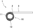
- FIG. 2 is a side view of an in-vivo indwelling device delivery system according to an embodiment of the present invention.
- FIG. 3 is a schematic diagram showing a method of measuring the reaction force of the coil of the in-vivo indwelling tool shown in FIG.
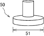
- FIG. 4 is a schematic diagram of the indenter shown in FIG.
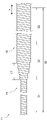
- FIG. 5 is an enlarged side view of the coil shown in FIG.
- FIG. 6 is a side view showing a modified example of the coil shown in FIG.
- FIG. 7 is a side view showing a modified example of the coil shown in FIG.
- the in-vivo indwelling tool 10 includes a coil 11 and a stretch resistance member 20. Further, the in-vivo indwelling device delivery system 1 includes an in-vivo indwelling device 10 and a pusher 3.
- the coil 11 has a distal end and a proximal end in the longitudinal axis direction x.
- the proximal side of the coil 11 refers to the direction toward the user or the operator's hand side with respect to the longitudinal axis direction x of the coil 11, and the direction opposite to the distal side to the proximal side, that is, the direction toward the treatment target side. Point to.
- the coil 11 is a coil 11 in which one or more wire rods 12 are spirally wound.
- the wire rod 12 is preferably a single wire, but may be a stranded wire. It is preferable that the wire rod 12 is not a coil body.
- a coil formed by spirally winding the wire rod 12 is sometimes called a primary coil.
- a secondary coil is a coil in which the primary coil is further habituated into a spiral or three-dimensional shape.
- FIG. 1 shows a state in which the coil 11 is linearly expanded, and when the coil 11 is given a secondary shape, the state of the primary coil in which the secondary coil is linearly extended is shown.
- the coil 11 has a lumen 11a extending in the longitudinal axis direction x thereof.
- the coil 11 may be a single-layer coil or a multi-layer coil having a plurality of layers.
- a part of the coil 11 in the longitudinal axis direction x may be a single layer, and the remaining part may be a plurality of layers.
- FIG. 1 shows an example in which the coil 11 is a single layer over the entire longitudinal axis direction x.
- the density of the coil 11, that is, the winding interval is not particularly limited, and tight winding, pitch winding, or a combination thereof can be used.
- adjacent wire rods 12 may be in contact with each other in a part of the longitudinal axis direction x, or adjacent wire rods 12 may be in contact with each other over the entire longitudinal axis direction x.
- a state in which adjacent wire rods 12 are in contact with each other in the longitudinal axis direction x of the coil 11 is called tight winding, and a state in which they are not in contact is called pitch winding.
- the non-contact state means a state in which the wires 12 adjacent to each other are open in the longitudinal axis direction x of the coil 11.
- the shape of the cross section perpendicular to the longitudinal axis direction x of the coil 11 may be a circular shape, an oval shape, a polygonal shape, or a combination thereof.
- the oval shape includes an elliptical shape, an egg shape, and a rectangular shape with rounded corners. The same applies to the following description.
- the maximum outer diameter and the minimum outer diameter of the coil 11 are not particularly limited and can be appropriately selected depending on the phase of the procedure.
- the coil 11 may be 150 ⁇ m or more, 180 ⁇ m or more, or 200 ⁇ m or more, and 400 ⁇ m or less. It is also permissible to be 380 ⁇ m or less, or 350 ⁇ m or less.
- the wire rod 12 preferably has biocompatibility and flexibility.
- Examples of the material constituting the wire rod 12 include platinum, gold, titanium, tungsten and alloys thereof, metal materials such as stainless steel, and combinations thereof. Above all, it is more preferable that the wire rod 12 is made of a platinum-tungsten alloy.
- the shape of the cross section perpendicular to the longitudinal axis direction of the wire rod 12 may be a circular shape, an oval shape, a polygonal shape, or a combination thereof.
- the outer diameter of the wire rod 12 is not particularly limited, but may be, for example, 25 ⁇ m or more, 30 ⁇ m or more, or 35 ⁇ m or more, and 75 ⁇ m or less, or 70 ⁇ m or less is acceptable.
- the wire rod 12 has a distal end and a proximal end in the longitudinal axis direction thereof.
- the wire rod 12 may be composed of a single linear member from the distal end to the proximal end, or may be composed of a plurality of linear members connected to each other in the longitudinal axis direction.
- the coil 11 has a head portion 13 at its distal end.
- the head portion 13 covers a part of the wire rod 12 in order to prevent the distal end of the wire rod 12 from coming into direct contact with the inner wall of the blood vessel.
- the head portion 13 may or may not be in contact with the extension resistance member 20 described later.
- the shape of the head portion 13 is not particularly limited, but may be, for example, hemispherical, semi-oval, cylindrical, or polygonal columnar.
- the head portion 13 may be joined to at least one of the outer surface and the inner surface of the coil 11. Further, in order to prevent the head portion 13 from falling off, a part of the head portion 13 may be arranged in the lumen 11a at the distal end portion of the coil 11. The proximal end of the head portion 13 may be located distal to the distal end of the wire 12, and the proximal end of the head 13 may be located proximal to the distal end of the wire 12. May be.
- the head portion 13 may be made of a metal material or a resin.
- the resin constituting the head portion 13 include a thermoplastic resin and an ultraviolet curable resin.
- an ultraviolet curable resin eliminates the need for a heat source when joining to the wire rod 12.
- the resin constituting the head portion 13 an epoxy acrylate-based resin, a urethane acrylate-based resin, or a polyester acrylate-based resin can be used.
- the metal constituting the head portion 13 the metal mentioned in the description of the wire rod 12 can be used.
- the materials of the wire rod 12 and the head portion 13 may be the same or different.
- the extension resistance member 20 suppresses the coil 11 from extending in the longitudinal axis direction x during operation.
- the extension resistance member 20 is arranged in the lumen 11a of the coil 11.
- the stretch resistance member 20 may be a long member made of a single wire or a stranded wire.
- the stretch resistance member 20 has a first end and a second end in the longitudinal axis direction.
- the stretch resistance member 20 may be a single layer or a multilayer body having a plurality of layers.
- the stretch resistance member 20 may have an inner layer made of a twisted wire made of a plurality of wires and an outer layer made of a resin composition provided on the outside of the inner layer.
- One extension resistance member 20 may be arranged in the lumen 11a, or a plurality of extension resistance members 20 may be arranged.
- the stretch resistance member 20 may be made of resin or metal.
- the resin constituting the stretch resistance member 20 include a polyester resin such as polyethylene terephthalate, a polyamide resin such as nylon, and a polyolefin resin such as polyethylene and polypropylene.
- the resin enhances the flexibility and improves the delivery performance of the indwelling tool 10. Further, since the stretch resistance member 20 is made of resin, it is possible to eliminate breakage due to metal fatigue during delivery. By making the length of the extension resistance member 20 longer than the length of the coil 11 or by using a material that is easily stretchable for the extension resistance member 20, the length of the extension resistance member 20 becomes longer when the coil 11 is arranged in the knob.
- the metal constituting the stretch resistance member 20 include platinum, gold, rhodium, palladium, renium, gold, silver, nickel, titanium, tantalum, tungsten, alloys thereof, and stainless steel.
- the extension resistance member 20 may be made of a material different from the wire rod 12 constituting the coil 11.
- the coil 11 may be made of a platinum-tungsten alloy
- the stretch resistance member 20 may be made of a polypropylene resin.
- the extension resistance member 20 may have a circular shape, an oval shape, a polygonal shape, or a combination thereof in a cross-sectional shape perpendicular to the longitudinal axis direction.
- the outer diameter of the extension resistance member 20 is required to be smaller than the inner diameter of the coil 11. Therefore, the outer diameter of the extension resistance member 20 is preferably smaller than one-half of the inner diameter of the coil 11, and more preferably one-third or less. In order to prevent the extension resistance member 20 from breaking, the outer diameter of the extension resistance member 20 is preferably 1/15 or more, and more preferably 1/10 or more of the inner diameter of the coil 11.
- the stretch resistance member 20 can be linear, wavy, or spiral.
- the stretch resistance member 20 can be smoothly placed up to the end of the coil 11, and the length of the stretch resistance member 20 is secured in the lumen 11a of the coil 11. be able to.
- the extension resistance member 20 may be connected to the distal end portion of the coil 11, for example, may be connected to the distal end portion of the wire rod 12 constituting the coil 11.
- the first end side of the extension resistance member 20 in the longitudinal axis direction may be connected to the distal end portion of the coil 11.
- the second end side of the stretch resistance member 20 in the longitudinal axis direction may be connected to the detaching portion 2 of the in-vivo indwelling device delivery system 1, which will be described later.
- the second end side of the extension resistance member 20 in the longitudinal axis direction may be connected to the proximal end of the coil 11, for example, the proximal end of the wire rod 12 constituting the coil 11.
- the second end side of the extension resistance member 20 in the longitudinal axis direction may be connected to the connection portion between the coil 11 and the pusher 3.
- the extension resistance member 20 is arranged in the lumen 11a of the coil 11 in a state of being folded back in the middle of the longitudinal axis direction thereof, and the folded portion 21 of the extension resistance member 20 is the distal end of the wire rod 12. It may be connected to the unit. In that case, the first end side and the second end side in the longitudinal axis direction of the extension resistance member 20 can be connected to the proximal end portion of the coil 11, the detachment portion 2, or the connection portion between the coil 11 and the pusher 3. .
- the folded-back portion 21 of the stretch resistance member 20 is hooked on the distal end portion of the coil 11, and the first end side and the second end side of the stretch resistance member 20 are connected to the distal end portion of the detachment portion 2. Has been done.
- connection method between the extension resistance member 20 and other members includes methods such as welding, welding, crimping such as caulking, bonding with an adhesive, engagement, connection, binding, physical fixing such as ligation, or these.
- connection includes a mode in which two elements are directly connected and a mode in which two elements are indirectly connected via one or more other elements.
- the in-vivo indwelling device delivery system 1 is attached to the indwelling device 10, the detaching portion 2 connected to the proximal end of the indwelling instrument 10, and the coil 11 of the indwelling instrument 10 via the detaching portion 2. It is preferable to include the connected pusher 3.
- the method of disengaging the indwelling tool 10 and the pusher 3 is as follows: a method of chemically dissolving, electrolyzing, or thermally dissolving the detaching portion 2, a method of pushing out the indwelling tool 10 by water pressure, a method of disengaging mechanical engagement, and a method of electrically disengaging the detaching portion 2. Examples include a method of disassembling. Further, a method of melting the resin wire rod as the detachment portion 2 by applying a high frequency current is preferably used. In that case, a high frequency power supply device is connected to the pusher 3. By generating Joule heat at the distal end portion of the pusher 3 by the high frequency power supply device, the detaching portion 2 connecting the indwelling tool 10 and the pusher 3 can be blown.
- the detaching portion 2 is not particularly limited as long as the indwelling tool 10 and the pusher 3 can be detached, but may be, for example, a linear or rod-shaped member.
- the detaching portion 2 can be made of resin or metal.
- PVA polyvinyl alcohol
- a PVA crosslinked polymer a PVA crosslinked polymer
- a PVA water-absorbing gel freeze-thaw elastomer a PVA water-absorbing gel freeze-thaw elastomer
- an ethylene vinyl alcohol copolymer or the like
- a hydrophilic resin of a synthetic polymer substance such as a polyvinyl alcohol-based polymer.
- the pusher 3 is a rod-shaped or linear member used to hold the indwelling tool 10 and push it to the distal side.
- the pusher 3 can be composed of one or a plurality of members.
- the pusher 3 may be composed of a wire member, a coil member, or a combination thereof.
- the pusher 3 can be made of a conductive material such as stainless steel.
- the pusher 3 may be provided with an X-ray contrast marker in order to grasp the position of the indwelling tool 10 in the body. It is preferable that an X-ray contrast marker is provided at at least one of the distal end and the proximal end of the pusher 3.
- the contrast marker may be ring-shaped or coil-shaped.
- a protective layer may be provided on the outer surface of the pusher 3.
- the protective layer is preferably made of a fluororesin such as polytetrafluoroethylene (PTFE). The protective layer enhances the slidability of the pusher 3 with other members such as catheters.
- the in-vivo indwelling device delivery system 1 includes a pusher 3 detachably connected to the proximal end of the coil 11, and the outer diameter of the distal end of the pusher 3 is the coil 11. It is preferably larger than the outer diameter of the proximal end. As a result, even if the coil 11 is pushed to the distal side by the pusher 3, the coil 11 is less likely to buckle.
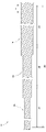
- the coil 11 has a main section 30 excluding both ends 5% of the length in the longitudinal axis direction x, and the main section 30 is divided into a distal section 31, a central section 32, and a proximal section 33.
- the average value of the outer diameter of the coil 11 in the central section 32 is equal to or less than the average value of the outer diameter of the coil 11 in the proximal section 33, and the average value of the outer diameter of the coil 11 in the distal section 31.
- the average value of the outer diameter of the coil 11 in the distal section 31 is smaller than the average value of the outer diameter of the coil 11 in the proximal section 33. ..
- the central section 32, and the proximal section 33 since the average value of the outer diameters of the coils 11 is set as described above in the distal section 31, the central section 32, and the proximal section 33, one coil 11 is close to the distal side. It can be made more flexible toward the rank side. As a result, even in the latter half of the process of feeding one coil 11 into the knob, since the coil 11 is flexible, it becomes easy to insert and fill the coil 11 smoothly, which contributes to the efficiency of the procedure. ..
- the section is virtually set to calculate the average value of the outer diameter in a certain range of the longitudinal axis direction x of the coil 11.
- Dividing the main section 30 into the distal section 31, the central section 32, and the proximal section 33 in three equal parts means that the main section 30 is virtually divided into the distal section 31, the central section 32, and the proximal section 33 into three equal parts.
- the above section is defined by the state in which the coil 11 is linearly expanded, and when the coil 11 is given a secondary shape, it is defined by the state of the primary coil in which the secondary coil is linearly extended.
- the outer diameters of the distal section 31, the central section 32, and the proximal section 33 of the coil 11 are measured by the following method.
- M measurement points are set in each of the distal section 31, the central section 32, and the proximal section 33.
- M is an integer of 10 or more and 300 or less. Measurement points shall be placed at the distal and proximal ends of each section.
- the outer diameter of the coil 11 is measured using a projection dimension measuring device, an imaging dimension measuring device, or the like, in addition to a caliper or a micrometer.
- the state in which the primary coil itself of the coil 11 or the secondary coil is linearly extended In order to keep the coil 11 in a linearly extended state, a holder or a tube member through which the coil 11 can be inserted can be used.
- the outer diameter of the linear coil 11 is directly measured, or the outer diameter of the coil 11 is indirectly measured using an image obtained by projecting or photographing the linear coil 11. The same measurement method is used for each section.
- the average value of the outer diameter of the coil 11 in the distal section 31 is smaller than the average value of the outer diameter of the coil 11 in the central section 32.
- the average value of the outer diameter of the coil 11 in the distal section 31 is preferably 90% or less, more preferably 80% or less of the average value of the outer diameter of the coil 11 in the central section 32. , 70% or less is more preferable. It is possible to make a difference in the flexibility of the coil 11 between the distal section 31 and the central section 32 to the extent that the operator can experience it.
- the average value of the outer diameter of the coil 11 in the central section 32 is smaller than the average value of the outer diameter of the coil 11 in the proximal section 33.
- the average value of the outer diameter of the coil 11 in the distal section 31 is preferably 20% or more, more preferably 30% or more of the average value of the outer diameter of the coil 11 in the central section 32. , 40% or more is more preferable. Thereby, the strength of the coil 11 can be secured in the distal section 31.
- the average value of the outer diameter of the coil 11 in the central section 32 is preferably 90% or less, more preferably 80% or less of the average value of the outer diameter of the coil 11 in the proximal section 33. , 70% or less is more preferable. It is possible to make a difference in the flexibility of the coil 11 between the central section 32 and the proximal section 33 to the extent that the operator can experience it.
- the average value of the outer diameter of the coil 11 in the central section 32 is preferably 20% or more, more preferably 30% or more of the average value of the outer diameter of the coil 11 in the proximal section 33. , 40% or more is more preferable. Thereby, the strength of the coil 11 can be secured in the central section 32.
- the outer diameter of the coil 11 used to define the pushing amount of the indenter 50 is the outer diameter of the coil 11 at the measurement point of the reaction force. The same applies to the following description.
- the reaction applied to the indenter 50 in the proximal section 33 When the disc-shaped indenter 50 is pushed in at a predetermined speed by a size of 5% of the outer diameter of the coil 11 from the direction perpendicular to the longitudinal axis direction x with respect to the coil 11, the reaction applied to the indenter 50 in the proximal section 33.
- the force is preferably 0.9 times or less, and may be 0.8 times or less, or 0.7 times or less the magnitude of the reaction force applied to the indenter 50 in the distal section 31.
- the reaction applied to the indenter 50 in the proximal section 33 When the disc-shaped indenter 50 is pushed in at a predetermined speed by a size of 5% of the outer diameter of the coil 11 from the direction perpendicular to the longitudinal axis direction x with respect to the coil 11, the reaction applied to the indenter 50 in the proximal section 33.
- the force is preferably 0.3 times or more, and may be 0.4 times or more, or 0.5 times or more the magnitude of the reaction force applied to the indenter 50 in the distal section 31.
- the force is preferably 0.9 times or less, and may be 0.8 times or less, or 0.7 times or less the magnitude of the reaction force applied to the indenter 50 in the central section 32.
- the force is preferably 0.3 times or more, and may be 0.4 times or more, or 0.5 times or more the magnitude of the reaction force applied to the indenter 50 in the central section 32.
- the reaction force of the coil 11 is measured by the following procedure.
- the measuring instrument including the sample table and the universal tester are omitted.
- N measurement points are set in the distal section 31, the central section 32, and the proximal section 33, respectively.
- N is an integer of 1 or more and 10 or less.
- the measurement points are set at equal intervals in the longitudinal axis direction x of the coil 11.
- the coil 11 is placed on the sample table of the measuring instrument in a linearly extended state.
- the indenter 50 is pushed at a predetermined speed from a direction z perpendicular to the longitudinal axis direction x with respect to the coil 11 at each measurement point by a size of 5% of the outer diameter of the coil 11.
- the reaction force (unit: N) applied to the indenter 50 when the indenter 50 is pressed against the coil 11 at each measurement point is measured.
- the average value of the reaction forces measured at a plurality of measurement points in each section is used for comparison.
- the moving speed of the indenter 50 is not particularly limited, but may be set to, for example, 3 ⁇ m / sec or more, 5 ⁇ m / sec or more, or 30 ⁇ m / sec or less, 25 ⁇ m / sec or less.
- a holder or a tube member through which the coil 11 can be inserted can be used.
- the coil 11 may be fixed to the surface of the sample table in order to prevent the coil 11 from being displaced during the measurement of the reaction force.
- the indenter 50 uses a disk-shaped portion in contact with the coil 11.
- the outer diameter 51 of the disk-shaped indenter 50 may be larger than the outer diameter of the coil 11 at the measurement point, but may be, for example, 0.5 times or more the outer diameter of the coil 11 at the measurement point. .. Further, the outer diameter 51 of the indenter 50 may be 0.7 times or more and 1 times or more the outer diameter of the coil 11 at the measurement point, and may be 3 times or less, 2.7 times or less, and 2.5 times or less. It can also be set to a size.
- the constituent material of the indenter is not limited, but can be composed of, for example, a cemented carbide such as stainless steel, diamond, sapphire, and tungsten carbide (WC).
- the coil 11 does not have a portion in the main section 30 whose outer diameter decreases from the distal side to the proximal side.
- the coil 11 is located proximal to the first coil portion 15 having a constant outer diameter and the first coil portion 15, and has a constant outer diameter and as a whole. It is preferable to have a second coil portion 16 having an outer diameter larger than that of the first coil portion 15.
- the fact that the outer diameter of the first coil portion 15 or the second coil portion 16 is constant means that the outer diameter of the coil 11 of the portion is substantially constant in the longitudinal axis direction x of the coil 11.
- the change in the outer diameter of the coil 11 in the portion includes the coil 11 within the range of ⁇ 5%.
- the outer diameter of the second coil portion 16 is preferably 1.02 times or more, more preferably 1.05 times or more, and 1.08 times or more the outer diameter of the first coil portion 15. Is even more preferable. Further, the outer diameter of the second coil portion 16 may be 1.3 times or less, 1.25 times or less, or 1.2 times or less the outer diameter of the first coil portion 15. It is also acceptable. By setting the outer diameter of the coil 11 in this way, it is easy to flexibly form the coil 11 from the distal side to the proximal side of the coil 11 while ensuring the strength of the coil 11 in the entire longitudinal axis direction x. Become.
- the second coil portion 16 is longer than the first coil portion 15 in the longitudinal axis direction x of the coil 11. By setting the length of the second coil portion 16 in this way, the flexibility of the coil 11 can be increased in a wide range in the longitudinal axis direction x of the coil 11.
- the first coil portion 15 may be longer than the second coil portion 16 in the longitudinal axis direction x of the coil 11. As a result, a portion of the coil 11 having lower flexibility in the longitudinal axis direction x of the coil 11 can be provided in a wider range than the first coil portion 15. Therefore, it can be preferably used in the steps of Framing to Filling.
- the lengths of the first coil portion 15 and the second coil portion 16 may be the same in the longitudinal axis direction x of the coil 11.
- the position of the first coil portion 15 in the longitudinal axis direction x of the coil 11 is not limited.
- at least a part of the first coil portion 15 may be located in the distal section 31.
- the first coil portion 15 may include the distal end of the distal section 31.
- the first coil portion 15 may include a portion on the distal end side in the longitudinal axis direction x with respect to the main section 30.
- the first coil portion 15 may be located in the distal section 31 and the central section 32.
- the first coil portion 15 may be located in the central section 32. Further, the first coil portion 15 may be located in the central section 32 and the proximal section 33. Further, the first coil portion 15 may be located in the proximal section 33.
- the position of the coil 11 in the longitudinal axis direction x is not limited.
- at least a part of the second coil portion 16 may be located in the central section 32.
- the second coil portion 16 may be located in the central section 32 and the proximal section 33.
- the second coil portion 16 may be located in the proximal section 33.
- the second coil portion 16 may include the proximal end of the proximal section 33.
- the second coil portion 16 may include a portion on the proximal end side in the longitudinal axis direction x with respect to the main section 30.
- the second coil portion 16 may be located in the distal section 31. Further, the second coil portion 16 may be located in the distal section 31 and the central section 32.
- the first coil portion 15 and the second coil portion 16 may be arranged next to each other.
- the portions having different outer diameters next to each other in this way, when the coil 11 is arranged in the knob, a bent portion is easily formed at the boundary between the first coil portion 15 and the second coil portion 16, and the coil 11 is easily formed. Is easy to form into a complicated shape that is bent in multiple directions.
- the coil 11 has a first transition portion 17 whose outer diameter decreases toward the distal side between the first coil portion 15 and the second coil portion 16. preferable. As a result, the flexibility of the coil 11 can be gradually increased from the second coil portion 16 toward the first coil portion 15.
- the outer diameter of the coil 11 may be tapered toward the distal side.
- the flexibility of the coil 11 can be gradually increased from the second coil portion 16 toward the first coil portion 15. Further, the coil 11 can be smoothly inserted into the knob.
- the tapered shape means that the outer diameter of the wire rod 12 constituting the coil 11 is reduced for each winding, and as a result, the envelope of the outer diameter of the coil 11 is tapered in the first transition portion 17. include. The same applies to the second transition unit 19 described later.
- FIG. 7 shows a modified example of the first transition unit 17.
- the outer diameter of the coil 11 may be gradually reduced toward the distal side.
- the stepped shape includes a mode in which the outer diameter of the wire rod 12 constituting the coil 11 is reduced for each number of turns of at least two or more turns. The same applies to the second transition unit 19 described later.
- the outer diameter of the coil 11 decreases toward the distal side every three turns in the first transition portion 17.
- the first transition portion 17 may be longer than the first coil portion 15 in the longitudinal axis direction x. Further, in the longitudinal axis direction x, the first transition portion 17 may be longer than the second coil portion 16. By providing the first transition portion 17 for a long time in this way, the flexibility can be gradually changed in a wide range in the longitudinal axis direction x of the coil 11.
- the first transition portion 17 may be shorter than the first coil portion 15 in the longitudinal axis direction x. Further, in the longitudinal axis direction x, the first transition portion 17 may be shorter than the second coil portion 16. By making the first transition portion 17 relatively short in this way, the flexibility can be changed in a short section of the coil 11 in the longitudinal axis direction x.
- the first transition portion 17 may be located in the distal section 31, may be located in the central section 32, or may be located in the proximal section 33. Further, the first transition portion 17 may be located in the distal section 31 and the central section 32, and the first transition portion 17 may be located in the central section 32 and the proximal section 33.
- FIG. 8 is a schematic view showing an example of the shape of the first coil portion of the coil shown in FIG. 1 in a state of being stationary without applying an external force.
- FIG. 9 is a schematic view showing an example of the shape of the portion between the first coil portion and the second coil portion of the coil shown in FIG. 1 in a state of being stationary without applying an external force.
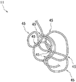
- FIG. 10 is a schematic view showing an example of a shape of a part of the main section of the coil of the in-vivo indwelling tool according to another embodiment of the present invention and in a state of standing still without applying an external force.
- the linear coil 11 shown in FIG. 1 may be habituated to have a complicated shape such as a planar shape or a three-dimensional shape. ..
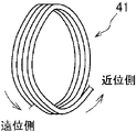
- the first coil portion 15 and the second coil portion 16 each form a first shape 41 in which the coil 11 forms an annular loop, and the coil 11 forms an annular loop.
- the second shape 42 which is curved without being formed, has a combined shape.
- the portion between the first coil portion 15 and the second coil portion 16 has a shape in which only the first shape 41 in which the coil 11 forms an annular loop is combined.
- the coil 11 is curved in multiple directions to form a complicated shape, so that it becomes easier to spread in the aneurysm, and as a result, the aneurysm It is possible to suppress the occurrence of rupture and damage.
- the first shape 41 is a shape in which the coil 11 forms a circumference of 360 degrees with the indwelling tool 10 standing still without applying an external force. That is, when observing the extending shape of the coil 11 from the proximal end side to the distal end side of the coil 11, it means that there is a portion extending in the opposite direction from the distal end side to the proximal end side. do.
- the second shape 42 is a shape in which the coil 11 is curved without forming an annulus in a state where the indwelling tool 10 is allowed to stand without applying an external force.
- FIG. 8 shows an example of a shape in which the first shape 41 and the second shape 42 are combined
- FIG. 9 shows an example of a shape in which only the first shape 41 is combined.
- the second shape 42 includes an arc shape, a wave shape, a meandering shape, a zigzag shape, a spiral shape (also referred to as a two-dimensional spiral shape or a spiral shape), and other random curved shapes without loops.
- the shape in which only the first shape 41 is combined includes a curve (helix) in which the coil 11 extends in a direction perpendicular to the circumferential surface while forming an annular loop.
- Such curves also include helices with smaller loop diameters towards the distal or proximal end of the coil 11.
- the shape in which only the first shape 41 is combined includes a shape in which a plurality of annular loops are connected and arranged in a circumferential shape.
- the direction of the central axes of the plurality of loops connected to each other may be along the radial direction of the circle having the circumference.
- the main section 30 of the coil 11 may be provided with three or more curved portions 45.
- the curved portion 45 By providing the curved portion 45 in this way, it becomes easy to form the coil 11 into a complicated shape curved in multiple directions.
- the number of curved portions 45 is not particularly limited.
- the number of curved portions 45 in the main section 30 may be, for example, 4 or more, 5 or more, 20 or less, 18 or less, and 15 or less.
- the coil 11 may form an annular loop by providing three or more curved portions 45 in the main section 30. One or more such loops may be provided in the main section 30. In the main section 30, another portion of the coil 11 may pass through the loop.
- a plurality of annular loops may be connected and arranged in a circumferential shape.
- the direction of the central axes of the plurality of loops connected to each other may be along the radial direction of the circle having the circumference.
- the coil 11 may be curved without forming an annular loop.
- the coil 11 may be curved in an arc shape, a wave shape, or any other random shape.
- FIG. 11 is a side view of the coil 11 according to still another embodiment of the present invention.
- 12 to 13 are side views showing a modified example of the coil 11 shown in FIG.
- the coil 11 has a third coil portion 18 in addition to the first coil portion 15 and the second coil portion 16. Specifically, the coil 11 is located proximal to the second coil portion 16, has a constant outer diameter, and has a third coil portion 18 having an outer diameter larger than that of the second coil portion 16 as a whole. You may have.
- the third coil portion 18 By providing the third coil portion 18 in this way, the flexibility of one coil 11 can be changed in at least three steps. As a result, even in the latter half of the process of feeding one coil 11 into the knob, the coil 11 is flexible, so that the coil 11 can be easily inserted and filled smoothly.
- the outer diameter of the third coil portion 18 is preferably 1.02 times or more, more preferably 1.05 times or more, and 1.08 times or more the outer diameter of the second coil portion 16. Is even more preferable. Further, the outer diameter of the third coil portion 18 may be 1.3 times or less, 1.25 times or less, or 1.2 times or less the outer diameter of the second coil portion 16. It is also acceptable. By setting the outer diameter of the coil 11 in this way, it becomes easy to secure the flexibility of the coil 11 in the proximal section 33 while ensuring the strength of the coil 11 in the entire longitudinal axis direction x.
- the outer diameter of the third coil portion 18 is preferably 1.01 times or more, more preferably 1.02 times or more, and 1.03 times or more the outer diameter of the first coil portion 15. Is even more preferable. Further, the outer diameter of the third coil portion 18 may be twice or less, 1.8 times or less, or 1.5 times or less the outer diameter of the first coil portion 15. Permissible. By setting the outer diameter of the coil 11 in this way, it becomes easy to secure the flexibility of the coil 11 in the proximal section 33 while ensuring the strength of the coil 11 in the entire longitudinal axis direction x.
- the third coil portion 18 may be longer than the second coil portion 16 in the longitudinal axis direction x of the coil 11. As a result, it becomes easy to provide a portion of the coil 11 having high flexibility over a wide range in the longitudinal axis direction x of the coil 11.
- the third coil portion 18 may be shorter than the second coil portion 16 in the longitudinal axis direction x of the coil 11. This makes it easy to provide a highly flexible portion of the coil 11 in a wide range in the longitudinal axis direction x of the coil 11.
- the lengths of the third coil portion 18 and the second coil portion 16 may be the same in the longitudinal axis direction x of the coil 11.
- the third coil portion 18 may be longer than the first coil portion 15 in the longitudinal axis direction x of the coil 11. As a result, it becomes easy to provide a portion of the coil 11 having high flexibility over a wide range in the longitudinal axis direction x of the coil 11.
- the third coil portion 18 may be shorter than the first coil portion 15 in the longitudinal axis direction x of the coil 11. As a result, it becomes easy to provide a portion of the coil 11 having low flexibility in a wide range in the longitudinal axis direction x of the coil 11.
- the lengths of the third coil portion 18 and the first coil portion 15 may be the same in the longitudinal axis direction x of the coil 11.
- the position of the coil 11 in the longitudinal axis direction x is not limited.
- at least a part of the third coil portion 18 may be located in the proximal section 33.
- the third coil portion 18 may include the proximal end of the proximal section 33.
- the third coil portion 18 may include a portion on the proximal end side in the longitudinal axis direction x with respect to the main section 30.
- the third coil portion 18 may be located in the central section 32 and the proximal section 33.
- the third coil portion 18 may be located in the central section 32. Further, the third coil portion 18 may be located in the central section 32 and the distal section 31. Further, the third coil portion 18 may be located in the distal section 31.
- the second coil portion 16 and the third coil portion 18 may be arranged next to each other.
- the portions having different outer diameters next to each other in this way, when the coil 11 is arranged in the knob, a bent portion is easily formed at the boundary between the second coil portion 16 and the third coil portion 18, and the coil 11 is easily formed. Is easy to form into a complicated shape that is bent in multiple directions.
- the first coil portion 15, the second coil portion 16, and the third coil portion 18 may be arranged next to each other.
- the portions having different outer diameters next to each other in this way, when the coil 11 is arranged in the knob, the boundary between the first coil portion 15 and the second coil portion 16 and the second coil portion 16 and the third coil portion are arranged. Bent portions are likely to be formed at the boundaries of the eighteen. As a result, it becomes easier to form the coil 11 due to the complicated shape bent in multiple directions.
- the coil 11 has a second transition portion 19 located between the second coil portion 16 and the third coil portion 18 and whose outer diameter decreases toward the distal side. It is preferable to have. As a result, the flexibility of the coil 11 can be gradually increased from the third coil portion 18 toward the second coil portion 16.
- the outer diameter of the coil 11 may be tapered toward the distal side. Further, in the second transition portion 19, the outer diameter of the coil 11 may be gradually reduced toward the distal side.
- the description of the first transition unit 17 can be referred to.
- the outer diameter of the coil 11 may be tapered toward the distal side. Further, in the first transition portion 17 and the second transition portion 19, the outer diameter of the coil 11 may be gradually reduced toward the distal side.
- One of the first transition portion 17 and the second transition portion 19 has the outer diameter of the coil 11 tapered toward the distal side, and the rest of the first transition portion 17 and the second transition portion 19. On the other hand, the outer diameter of the coil 11 may be gradually reduced toward the distal side.
- the second transition portion 19 may be longer than the second coil portion 16 in the longitudinal axis direction x. Further, in the longitudinal axis direction x, the second transition portion 19 may be longer than the third coil portion 18. By providing the second transition portion 19 for a long time in this way, the flexibility can be gradually changed in a wide range in the longitudinal axis direction x of the coil 11.
- the second transition portion 19 may be shorter than the second coil portion 16 in the longitudinal axis direction x. Further, in the longitudinal axis direction x, the second transition portion 19 may be shorter than the third coil portion 18. By making the second transition portion 19 relatively short in this way, the flexibility can be changed in a short section in the longitudinal axis direction x of the coil 11.
- the second transition portion 19 may be located in the distal section 31, may be located in the central section 32, or may be located in the proximal section 33. Further, the second transition portion 19 may be located in the distal section 31 and the central section 32, and the second transition portion 19 may be located in the central section 32 and the proximal section 33.
- the coil 11 has a first coil portion 15, a first transition portion 17, a second coil portion 16, a second transition portion 19, and a third coil portion. You may have 18.
- the coil 11 has the third coil portion 18 in addition to the first coil portion 15 and the second coil portion 16, the shape of the coil 11 in a stationary state without applying an external force will be described.
- the first coil portion 15 and the third coil portion 18 each form a first shape 41 in which the coil 11 forms an annular loop, and the coil 11 forms an annular loop.
- the second coil portion 16 has a shape in which only the first shape 41 in which the coil 11 forms an annular loop is combined. Is preferable.
- the coil 11 may have a fourth coil portion located between the first coil portion 15 and the second coil portion 16 and whose outer diameter changes periodically.
- the fourth coil portion When the fourth coil portion is inserted into the knob, the portions that are repeated in a specific pattern are fixed by engaging with each other and are less likely to be deformed. Since the skeleton of the coil 11 can be formed by the fourth coil portion, it can be suitably used for a procedure including a Framing phase.
- the periodic change in the outer diameter of the coil 11 means that the coil 11 is repeatedly arranged in a specific pattern in the longitudinal axis direction x.
- the specific pattern means that the outer shape of the coil 11 is a spherical shape, an elliptical shape, a semicircular shape, a semicircular spherical shape, a teardrop shape, a polygonal shape, a cone shape, a cone shape, or a linear shape. , A shape such as a cylinder shape, or a shape in which these are combined as one unit.
- the specific pattern includes a shape in which the outer diameter of the coil 11 is substantially constant (including a shape in which the change in the outer diameter of the coil 11 in the portion is within ⁇ 5%). Make it not exist. That is, the specific pattern does not include the first coil portion 15, the second coil portion 16, and the third coil portion 18.
- the fourth coil portion is longer than the first coil portion 15 in the longitudinal axis direction x of the coil 11.
- the first coil portion 15 may be longer than the fourth coil portion in the longitudinal axis direction x of the coil 11. As a result, the first coil portion 15 first forms a large frame of the skeleton of the coil 11, and then the fourth coil portion makes it easier to supplementarily increase the strength of the skeleton.
- the lengths of the first coil portion 15 and the fourth coil portion may be the same in the longitudinal axis direction x of the coil 11.
- the position of the fourth coil portion in the longitudinal axis direction x of the coil 11 is not limited.
- the fourth coil portion may be located in the distal section 31, may be located in the central section 32, or may be located in the proximal section 33. Further, the fourth coil portion may be located in the distal section 31 and the central section 32, or may be located in the central section 32 and the proximal section 33.
- the first coil portion 15 and the fourth coil portion may be arranged next to each other.
- the first coil portion 15 forms a large frame of the skeleton of the coil 11, and then the fourth coil portion facilitates a procedure for increasing the strength of the skeleton.
- the 4th coil portion and the 2nd coil portion 16 may be arranged next to each other. This facilitates the procedure of filling the gap of the frame with the flexible second coil portion 16 after increasing the strength of the skeleton by the fourth coil portion.
- a first small diameter portion 111 having an outer diameter smaller than that of the first coil portion 15 may be provided between the first coil portion 15 and the second coil portion 16.
- the coil 11 is easily bent at the first small diameter portion 111, and the coil 11 is easily formed into a complicated shape bent in multiple directions.
- the first small diameter portion 111 is shorter than the first coil portion 15 in the longitudinal axis direction x.
- the outer diameter of the coil 11 is constant.
- a second small diameter portion 112 having a smaller outer diameter than the second coil portion 16 may be provided between the second coil portion 16 and the third coil portion 18.
- the coil 11 is easily bent at the second small diameter portion 112, and the coil 11 is easily formed into a complicated shape bent in multiple directions.
- the second small diameter portion 112 is shorter than the second coil portion 16 in the longitudinal axis direction x.
- the second small diameter portion 112 is preferably shorter than the third coil portion 18.
- the outer diameter of the coil 11 is constant.
- the second small diameter portion 112 may have a larger or smaller outer diameter than the first small diameter portion 111, and may have the same outer diameter as the first small diameter portion 111.
- In-vivo indwelling tool delivery system 2 Detachment part 3: Pusher 10: In-vivo indwelling tool 11: Coil 11a: Cavity 12: Wire rod 13: Head part 15: First coil part 16: Second coil part 17: No. 1 Transition part 18: Third coil part 19: Second transition part 20: Stretch resistance member 21: Folded part 30: Main section 31: Distal section 32: Central section 33: Proximal section 41: First shape 42: First 2 Shape 45: Curved portion 50: Indenter x: Longitudinal axis direction
Landscapes
- Health & Medical Sciences (AREA)
- Surgery (AREA)
- Life Sciences & Earth Sciences (AREA)
- Heart & Thoracic Surgery (AREA)
- Nuclear Medicine, Radiotherapy & Molecular Imaging (AREA)
- Vascular Medicine (AREA)
- Engineering & Computer Science (AREA)
- Biomedical Technology (AREA)
- Reproductive Health (AREA)
- Medical Informatics (AREA)
- Molecular Biology (AREA)
- Animal Behavior & Ethology (AREA)
- General Health & Medical Sciences (AREA)
- Public Health (AREA)
- Veterinary Medicine (AREA)
- Surgical Instruments (AREA)
Priority Applications (1)
| Application Number | Priority Date | Filing Date | Title |
|---|---|---|---|
| JP2022555422A JP7830339B2 (ja) | 2020-10-05 | 2021-09-30 | 生体内留置具および生体内留置具送達システム |
Applications Claiming Priority (2)
| Application Number | Priority Date | Filing Date | Title |
|---|---|---|---|
| JP2020168493 | 2020-10-05 | ||
| JP2020-168493 | 2020-10-05 |
Publications (1)
| Publication Number | Publication Date |
|---|---|
| WO2022075183A1 true WO2022075183A1 (ja) | 2022-04-14 |
Family
ID=81126859
Family Applications (1)
| Application Number | Title | Priority Date | Filing Date |
|---|---|---|---|
| PCT/JP2021/036179 Ceased WO2022075183A1 (ja) | 2020-10-05 | 2021-09-30 | 生体内留置具および生体内留置具送達システム |
Country Status (2)
| Country | Link |
|---|---|
| JP (1) | JP7830339B2 (https=) |
| WO (1) | WO2022075183A1 (https=) |
Cited By (1)
| Publication number | Priority date | Publication date | Assignee | Title |
|---|---|---|---|---|
| WO2025126746A1 (ja) * | 2023-12-11 | 2025-06-19 | 株式会社カネカ | 生体内留置具の留置システムおよび生体内留置具の製造方法 |
Citations (2)
| Publication number | Priority date | Publication date | Assignee | Title |
|---|---|---|---|---|
| WO2010092174A2 (de) * | 2009-02-16 | 2010-08-19 | Justus-Liebig-Universität Giessen | Implantat |
| US20170164951A1 (en) * | 2012-01-20 | 2017-06-15 | Covidien Lp | Aneurysm treatment coils |
Family Cites Families (1)
| Publication number | Priority date | Publication date | Assignee | Title |
|---|---|---|---|---|
| WO2017086479A1 (ja) * | 2015-11-19 | 2017-05-26 | 株式会社カネカ | 生体内留置部材及び該生体内留置部材を備える生体内留置部材配置装置 |
-
2021
- 2021-09-30 WO PCT/JP2021/036179 patent/WO2022075183A1/ja not_active Ceased
- 2021-09-30 JP JP2022555422A patent/JP7830339B2/ja active Active
Patent Citations (2)
| Publication number | Priority date | Publication date | Assignee | Title |
|---|---|---|---|---|
| WO2010092174A2 (de) * | 2009-02-16 | 2010-08-19 | Justus-Liebig-Universität Giessen | Implantat |
| US20170164951A1 (en) * | 2012-01-20 | 2017-06-15 | Covidien Lp | Aneurysm treatment coils |
Cited By (1)
| Publication number | Priority date | Publication date | Assignee | Title |
|---|---|---|---|---|
| WO2025126746A1 (ja) * | 2023-12-11 | 2025-06-19 | 株式会社カネカ | 生体内留置具の留置システムおよび生体内留置具の製造方法 |
Also Published As
| Publication number | Publication date |
|---|---|
| JP7830339B2 (ja) | 2026-03-16 |
| JPWO2022075183A1 (https=) | 2022-04-14 |
Similar Documents
| Publication | Publication Date | Title |
|---|---|---|
| US20230210534A1 (en) | Vaso-occlusive devices and methods of use | |
| US20250318838A1 (en) | Embolic Occlusion Device And Method | |
| US11376012B2 (en) | Devices, systems, and methods for treatment of vascular defects | |
| JP7438935B2 (ja) | 外科用インプラントのための包装材 | |
| US20200367901A1 (en) | Embolic devices and methods of manufacturing same | |
| US10383635B2 (en) | Vaso-occlusive devices and methods of use | |
| KR101845115B1 (ko) | 스텐트 | |
| US20170245865A1 (en) | Intralumenal Occlusion Devices Having Improved Properties | |
| EP2555690B1 (en) | Vaso-occlusive devices | |
| JP2022554021A (ja) | ステント送給システムおよび方法 | |
| CN103200884A (zh) | 用于影响动静脉畸形中的血液流动的植入物 | |
| JP2005531390A (ja) | 軸方向の引伸ばしに抵抗する同軸脈管閉塞デバイス | |
| AU2003267287A1 (en) | Microcoil vaso-occlusive device with multi-axis secondary configuration | |
| US11103251B2 (en) | In vivo indwelling member, and in vivo indwelling member placement device provided with said in vivo indwelling member | |
| JP7063903B2 (ja) | 生体内留置具、生体内留置具送達システムおよび生体内留置具の製造方法 | |
| WO2022075183A1 (ja) | 生体内留置具および生体内留置具送達システム | |
| WO2022075182A1 (ja) | 生体内留置具および生体内留置具送達システム | |
| JP7097365B2 (ja) | 生体内留置具および生体内留置具送達システム | |
| WO2023248985A1 (ja) | 塞栓デバイス | |
| WO2022138384A1 (ja) | 塞栓システム | |
| WO2023248986A1 (ja) | 塞栓デバイス | |
| WO2022138383A1 (ja) | 塞栓デバイス | |
| WO2019054066A1 (ja) | 塞栓形成用体内留置具 |
Legal Events
| Date | Code | Title | Description |
|---|---|---|---|
| 121 | Ep: the epo has been informed by wipo that ep was designated in this application |
Ref document number: 21877484 Country of ref document: EP Kind code of ref document: A1 |
|
| ENP | Entry into the national phase |
Ref document number: 2022555422 Country of ref document: JP Kind code of ref document: A |
|
| NENP | Non-entry into the national phase |
Ref country code: DE |
|
| 122 | Ep: pct application non-entry in european phase |
Ref document number: 21877484 Country of ref document: EP Kind code of ref document: A1 |