WO2022075108A1 - 熱拡散デバイス - Google Patents
熱拡散デバイス Download PDFInfo
- Publication number
- WO2022075108A1 WO2022075108A1 PCT/JP2021/035365 JP2021035365W WO2022075108A1 WO 2022075108 A1 WO2022075108 A1 WO 2022075108A1 JP 2021035365 W JP2021035365 W JP 2021035365W WO 2022075108 A1 WO2022075108 A1 WO 2022075108A1
- Authority
- WO
- WIPO (PCT)
- Prior art keywords
- porous body
- wall surface
- flow path
- wick
- liquid flow
- Prior art date
- Legal status (The legal status is an assumption and is not a legal conclusion. Google has not performed a legal analysis and makes no representation as to the accuracy of the status listed.)
- Ceased
Links
Images










Classifications
-
- F—MECHANICAL ENGINEERING; LIGHTING; HEATING; WEAPONS; BLASTING
- F28—HEAT EXCHANGE IN GENERAL
- F28D—HEAT-EXCHANGE APPARATUS, NOT PROVIDED FOR IN ANOTHER SUBCLASS, IN WHICH THE HEAT-EXCHANGE MEDIA DO NOT COME INTO DIRECT CONTACT
- F28D15/00—Heat-exchange apparatus with the intermediate heat-transfer medium in closed tubes passing into or through the conduit walls ; Heat-exchange apparatus employing intermediate heat-transfer medium or bodies
- F28D15/02—Heat-exchange apparatus with the intermediate heat-transfer medium in closed tubes passing into or through the conduit walls ; Heat-exchange apparatus employing intermediate heat-transfer medium or bodies in which the medium condenses and evaporates, e.g. heat pipes
-
- F—MECHANICAL ENGINEERING; LIGHTING; HEATING; WEAPONS; BLASTING
- F28—HEAT EXCHANGE IN GENERAL
- F28D—HEAT-EXCHANGE APPARATUS, NOT PROVIDED FOR IN ANOTHER SUBCLASS, IN WHICH THE HEAT-EXCHANGE MEDIA DO NOT COME INTO DIRECT CONTACT
- F28D15/00—Heat-exchange apparatus with the intermediate heat-transfer medium in closed tubes passing into or through the conduit walls ; Heat-exchange apparatus employing intermediate heat-transfer medium or bodies
- F28D15/02—Heat-exchange apparatus with the intermediate heat-transfer medium in closed tubes passing into or through the conduit walls ; Heat-exchange apparatus employing intermediate heat-transfer medium or bodies in which the medium condenses and evaporates, e.g. heat pipes
- F28D15/04—Heat-exchange apparatus with the intermediate heat-transfer medium in closed tubes passing into or through the conduit walls ; Heat-exchange apparatus employing intermediate heat-transfer medium or bodies in which the medium condenses and evaporates, e.g. heat pipes with tubes having a capillary structure
Definitions
- the present invention relates to a heat diffusion device.
- the vapor chamber has a structure in which a working medium and a wick that transports the working medium by capillary force are enclosed inside the housing.
- the working medium absorbs heat from the heat generating element in the evaporation unit that absorbs heat from the heat generating element and evaporates in the vapor chamber, then moves in the vapor chamber, is cooled, and returns to the liquid phase.
- the working medium that has returned to the liquid phase moves to the evaporation part on the heat generating element side again by the capillary force of the wick, and cools the heat generating element.
- the vapor chamber operates independently without having external power, and can diffuse heat two-dimensionally at high speed by utilizing the latent heat of vaporization and the latent heat of condensation of the working medium.
- the vapor chamber is also required to be thinner in order to support the thinner mobile terminals such as smartphones and tablets. In such a thin vapor chamber, it becomes difficult to secure mechanical strength and heat transfer efficiency.
- the wick arranged inside the housing is to maintain the shape of the housing. It has been proposed to be used as a support for.
- the first wick portion and the second wick portion are arranged at intervals in the left-right direction, and a liquid pool portion formed between the first wick portion and the second wick portion. Is filled with the working medium of the liquid phase.
- the working medium of the liquid phase can be reliably returned to the evaporating part through the liquid pool part, so that the flow of the working medium of the liquid phase can be prevented from being stagnant. It is said that the decrease in heat transport efficiency can be suppressed.
- the above problem is not limited to the vapor chamber, but is a problem common to heat diffusion devices capable of diffusing heat by the same configuration as the vapor chamber.
- the present invention has been made to solve the above problems, and an object of the present invention is to provide a heat diffusion device in which a decrease in thermal conductivity is suppressed and a maximum heat transport amount is large. It is also an object of the present invention to provide an electronic device provided with the heat diffusion device.
- the heat diffusion device of the present invention has a housing having a first inner wall surface and a second inner wall surface facing each other in the thickness direction, an actuating medium enclosed in the internal space of the housing, and the internal space of the housing. Equipped with a placed wick.
- the housing has an evaporation unit that evaporates the working medium.
- the wick includes a plurality of wicks extending linearly from the evaporation portion and at least partially in contact with the inner wall surface of at least one of the first inner wall surface and the second inner wall surface.
- a steam flow path is formed between at least one set of adjacent wick bodies. In the adjacent wick bodies, a first liquid flow path is formed in a space surrounded by at least a part of each of the wick bodies and a part of the housing.
- a second liquid flow path is formed by providing a groove along the direction in which the wick body extends on at least one of the surfaces of the wick body in contact with the first inner wall surface or the second inner wall surface. Has been done.
- the electronic device of the present invention includes the heat diffusion device of the present invention.
- FIG. 1 is a perspective view schematically showing an example of a vapor chamber according to the first embodiment of the present invention.
- FIG. 2 is a cross-sectional view taken along the line II-II of the vapor chamber shown in FIG.
- FIG. 3 is a cross-sectional view taken along the line III-III of the vapor chamber shown in FIG.
- FIG. 4 is an enlarged cross-sectional view of the portion shown by IV in FIG.
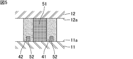
- FIG. 5 is a cross-sectional view schematically showing a first modification example of the position where the second liquid flow path is formed.
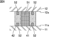
- FIG. 6 is a cross-sectional view schematically showing a second modification example of the position where the second liquid flow path is formed.
- FIG. 1 is a perspective view schematically showing an example of a vapor chamber according to the first embodiment of the present invention.
- FIG. 2 is a cross-sectional view taken along the line II-II of the vapor chamber shown in FIG.
- FIG. 3 is a cross-sectional view taken along the
- FIG. 7 is a cross-sectional view schematically showing a modified example of the cross-sectional shape of the second liquid flow path.
- FIG. 8 is a cross-sectional view schematically showing an example of a vapor chamber according to a second embodiment of the present invention.
- FIG. 9 is a cross-sectional view schematically showing an example of a vapor chamber according to a third embodiment of the present invention.
- FIG. 10 is a cross-sectional view schematically showing an example of a vapor chamber according to a fourth embodiment of the present invention.
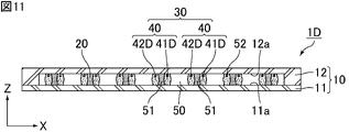
- FIG. 11 is a cross-sectional view schematically showing an example of a vapor chamber according to a fifth embodiment of the present invention.
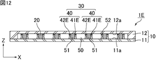
- FIG. 12 is a cross-sectional view schematically showing an example of a vapor chamber according to a sixth embodiment of the present invention.
- FIG. 13 is a plan view schematically showing an example of the vapor chamber according to the seventh embodiment of the present invention.
- FIG. 14 is a plan view schematically showing an example of the vapor chamber according to the eighth embodiment of the present invention.
- FIG. 15 is a plan view schematically showing an example of the vapor chamber according to the ninth embodiment of the present invention.
- FIG. 16 is a plan view schematically showing an example of the vapor chamber according to the tenth embodiment of the present invention.
- FIG. 17 is a plan view schematically showing an example of the vapor chamber according to the eleventh embodiment of the present invention.
- FIG. 18 is a cross-sectional view schematically showing an example of a vapor chamber according to the eleventh embodiment of the present invention.
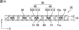
- FIG. 19 is a cross-sectional view schematically showing an example of a vapor chamber according to a twelfth embodiment of the present invention.
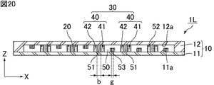
- FIG. 20 is a cross-sectional view schematically showing an example of a vapor chamber according to a thirteenth embodiment of the present invention.
- FIG. 21 is a cross-sectional view schematically showing an example of a vapor chamber according to the 14th embodiment of the present invention.
- FIG. 22 is a cross-sectional view schematically showing an example of the vapor chamber according to the fifteenth embodiment of the present invention.
- FIG. 23 is a cross-sectional view schematically showing another example of the vapor chamber according to the fifteenth embodiment of the present invention.
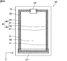
- FIG. 24 is a plan view schematically showing an example of the vapor chamber according to the 16th embodiment of the present invention.
- FIG. 25 is a plan view schematically showing an example of the vapor chamber according to the 17th embodiment of the present invention.
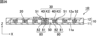
- FIG. 26 is a cross-sectional view schematically showing an example of a vapor chamber according to an eighteenth embodiment of the present invention.
- FIG. 27 is an enlarged cross-sectional view of the portion shown by XXVII in FIG. 26.
- the present invention is not limited to the following configuration, and can be appropriately modified and applied without changing the gist of the present invention. It should be noted that a combination of two or more of the individual desirable configurations of the present invention described below is also the present invention.
- heat diffusion device of the present invention when each embodiment is not particularly distinguished, it is simply referred to as "heat diffusion device of the present invention".
- a vapor chamber will be described as an example of an embodiment of the heat diffusion device of the present invention.
- the heat diffusion device of the present invention can also be applied to a heat diffusion device such as a heat pipe.
- FIG. 1 is a perspective view schematically showing an example of a vapor chamber according to the first embodiment of the present invention.
- FIG. 2 is a cross-sectional view taken along the line II-II of the vapor chamber shown in FIG.
- FIG. 3 is a cross-sectional view taken along the line III-III of the vapor chamber shown in FIG.
- the vapor chamber 1 shown in FIG. 1 includes a hollow housing 10 that is hermetically sealed. As shown in FIG. 3, the housing 10 has a first inner wall surface 11a and a second inner wall surface 12a facing each other in the thickness direction Z. As shown in FIGS. 2 and 3, the vapor chamber 1 further includes an actuating medium 20 enclosed in the internal space of the housing 10 and a wick 30 arranged in the internal space of the housing 10.
- the housing 10 is provided with an evaporation unit EP that evaporates the enclosed working medium 20. Further, the housing 10 may be set with a condensation portion CP for condensing the evaporated working medium 20.
- a heat source HS which is a heat generating element, is arranged on the outer wall surface of the housing 10. Examples of the heat source HS include electronic components of electronic devices, such as a central processing unit (CPU).
- CPU central processing unit
- the portion near the heat source HS and heated by the heat source HS corresponds to the evaporation portion EP.
- the portion away from the evaporation portion EP corresponds to the condensation portion CP.
- the evaporated working medium 20 can be condensed other than the condensed portion CP. In the present embodiment, a portion where the evaporated working medium 20 is particularly easy to condense is expressed as a condensing portion CP.
- the vapor chamber 1 is planar as a whole. That is, the housing 10 is planar as a whole.
- the "plane” includes a plate shape and a sheet shape, and the dimension in the width direction X (hereinafter referred to as "width") and the dimension in the length direction Y (hereinafter referred to as "length”) are in the thickness direction Z. It means a shape that is considerably larger than a dimension (hereinafter referred to as a thickness or a height), for example, a shape having a width and a length of 10 times or more, preferably 100 times or more the thickness.
- the size of the vapor chamber 1, that is, the size of the housing 10 is not particularly limited.
- the width and length of the vapor chamber 1 can be appropriately set according to the intended use.
- the width and length of the vapor chamber 1 are, for example, 5 mm or more and 500 mm or less, 20 mm or more and 300 mm or less, or 50 mm or more and 200 mm or less, respectively.
- the width and length of the vapor chamber 1 may be the same or different.
- the housing 10 is composed of the first sheet 11 and the second sheet 12 facing each other to which the outer edges are joined.
- the materials constituting the first sheet 11 and the second sheet 12 are not particularly limited as long as they have properties suitable for use as a vapor chamber, such as thermal conductivity, strength, flexibility, and flexibility.
- the material constituting the first sheet 11 and the second sheet 12 is preferably a metal, for example, copper, nickel, aluminum, magnesium, titanium, iron, or an alloy containing them as a main component, and particularly preferably copper. Is.
- the materials constituting the first sheet 11 and the second sheet 12 may be the same or different, but are preferably the same.
- the first sheet 11 and the second sheet 12 are joined to each other at their outer edges.
- the joining method is not particularly limited, but for example, laser welding, resistance welding, diffusion welding, brazing, TIG welding (tungsten-inert gas welding), ultrasonic welding, or resin encapsulation can be used, and is preferable. Can use laser welding, resistance welding or low welding.
- the thicknesses of the first sheet 11 and the second sheet 12 are not particularly limited, but are preferably 10 ⁇ m or more and 200 ⁇ m or less, more preferably 30 ⁇ m or more and 100 ⁇ m or less, and further preferably 40 ⁇ m or more and 60 ⁇ m or less, respectively.
- the thicknesses of the first sheet 11 and the second sheet 12 may be the same or different. Further, the thickness of each of the first sheet 11 and the second sheet 12 may be the same throughout, or a part thereof may be thin.
- the shapes of the first sheet 11 and the second sheet 12 are not particularly limited.
- the first sheet 11 has a flat plate shape having a constant thickness
- the second sheet 12 has a shape in which the outer edge portion is thicker than the portion other than the outer edge portion.
- the thickness of the entire vapor chamber 1 is not particularly limited, but is preferably 50 ⁇ m or more and 500 ⁇ m or less.
- the working medium 20 is not particularly limited as long as it can cause a gas-liquid phase change in the environment inside the housing 10, and for example, water, alcohols, CFC substitutes, or the like can be used.
- the working medium is an aqueous compound, preferably water.
- the wick 30 includes a plurality of wick bodies 40 extending linearly from the evaporation unit EP.
- the wick body 40 extends from the evaporation portion EP to the condensation portion CP. At least a part of the wick body 40 is in contact with at least one inner wall surface of the first inner wall surface 11a and the second inner wall surface 12a of the housing 10.
- the wick body 40 supports the first inner wall surface 11a and the second inner wall surface 12a of the housing 10 from the inside.
- the wick body 40 constituting the wick 30 is in contact with the first inner wall surface 11a and the second inner wall surface 12a.
- the wick body 40 may be in contact with either the first inner wall surface 11a or the second inner wall surface 12a.
- At least one set of adjacent wick bodies 40 includes a first porous body 41 and a second porous body 42, respectively. These porous bodies function as wicks that transport the working medium 20 by capillary force. Further, by using a porous body as a support of the housing 10, the weight of the vapor chamber 1 can be reduced.
- the first porous body 41 and the second porous body 42 are composed of, for example, a metal porous body, a ceramic porous body, or a resin porous body.
- the first porous body 41 and the second porous body 42 may be composed of a sintered body such as a metal porous sintered body or a ceramic porous sintered body, for example.
- the first porous body 41 and the second porous body 42 are preferably composed of a porous sintered body of copper or nickel.
- a steam flow path 50 through which the working medium 20 of the gas phase flows is formed between at least one set of adjacent wick bodies 40.
- the first liquid flow path 51 is formed in a space surrounded by at least a part of each wick body 40 and a part of the housing 10.
- the first liquid flow path 51 is formed in a space surrounded by a part of the first porous body 41, a part of the second porous body 42, and a part of the housing 10.
- the first liquid flow path 51 is provided by providing a space between the first porous body 41 and the second porous body 42 along the direction in which the wick body 40 extends. It is formed.
- the first liquid flow path 51 can be used as a liquid flow path through which the working medium 20 of the liquid phase flows.
- the heat transport efficiency can be improved by, for example, arranging the liquid flow path and the vapor flow path alternately with the wick body 40 sandwiched between the first porous body 41 or the second porous body 42.
- the width a of the vapor flow path 50 is larger than the width b of the first liquid flow path 51.
- the width a of the steam flow path 50 is preferably 1000 ⁇ m or more and 3000 ⁇ m or less, and more preferably 1000 ⁇ m or more and 2000 ⁇ m or less.
- the width b of the first liquid flow path 51 is preferably 50 ⁇ m or more and 500 ⁇ m or less.
- the width of the widest portion is defined as the width of the steam flow path.
- the width of the widest portion is defined as the width of the first liquid flow path.
- FIG. 4 is an enlarged cross-sectional view of the portion shown by IV in FIG.
- at least one of the surfaces of the wick body 40 in contact with the first inner wall surface 11a or the second inner wall surface 12a is provided with a groove portion along the direction in which the wick body 40 extends.
- the second liquid flow path 52 is formed by the above.
- the surface where the first porous body 41 is in contact with the first inner wall surface 11a, the surface where the first porous body 41 is in contact with the second inner wall surface 12a, and the second porous body 42 are the first.
- the surface in contact with the inner wall surface 11a and the second porous body 42 are formed on at least one of the surfaces in contact with the second inner wall surface 12a. Specifically, a groove portion is formed on the surface of the first porous body 41 facing the second inner wall surface 12a and the surface of the second porous body 42 facing the second inner wall surface 12a along the direction in which the wick body 40 extends.
- the second liquid flow path 52 is formed by the provision of the above. Similar to the first liquid flow path 51, the second liquid flow path 52 can be used as a liquid flow path through which the working medium 20 of the liquid phase flows.
- the second liquid is on the surface of the wick body 40 in contact with the first inner wall surface 11a or the second inner wall surface 12a, for example, the surface of the first porous body 41 or the second porous body 42 facing the second inner wall surface 12a of the housing 10.
- the flow path 52 By forming the flow path 52, it is possible to increase the number of liquid flow paths while maintaining the height of the steam flow path. Therefore, it is possible to suppress the decrease in thermal conductivity and increase the maximum heat transport amount. Further, by forming the flow path on the top surface or the bottom surface of the porous body, it becomes possible to smoothly flow the liquid to the heat source as compared with the case where the flow path is formed inside (central portion) of the porous body. ..
- the method for forming the second liquid flow path 52 is not particularly limited, but for example, when the first porous body 41 and the second porous body are composed of the porous sintered body, for producing the porous sintered body. Examples thereof include a method of adjusting the viscosity of the paste and a method of pressing after applying the paste by printing such as screen printing.
- the width e of the second liquid flow path 52 is smaller than either the width c 1 of the first porous body 41 or the width c 2 of the second porous body 42, and the height of the second liquid flow path 52 is high. It is preferable that the value f is smaller than either 1/2 of the height d 1 of the first porous body 41 and 1/2 of the height d 2 of the second porous body 42. That is, it is preferable that the relations of e ⁇ c 1 and e ⁇ c 2 and f ⁇ 1 / 2d 1 and f ⁇ 1 / 2d 2 are established.
- the width of the widest portion is defined as the width of the second liquid flow path.
- the width of the porous body is different in the thickness direction Z
- the width of the widest portion is defined as the width of the porous body.
- the height of the second liquid flow path is different in the width direction X
- the height of the highest portion is defined as the height of the second liquid flow path.
- the height of the porous body differs in the width direction X
- the height of the highest portion is defined as the height of the porous body.
- the width e of the second liquid flow path 52 is preferably smaller than either the width c 1 of the first porous body 41 or the width c 2 of the second porous body 42, but the width e of the first porous body 41 It may be the same as at least one of the width c 1 and the width c 2 of the second porous body 42.
- the width c 1 of the first porous body 41 and the width c 2 of the second porous body 42 are preferably 50 ⁇ m or more and 300 ⁇ m or less, respectively. This makes it possible to obtain a high capillary force.
- the width c 1 of the first porous body 41 may be the same as or different from the width c 2 of the second porous body 42.
- the width c 1 of the first porous body 41 and the width c 2 of the second porous body 42 do not have to be constant in the thickness direction Z. Further, a porous body having a constant width in the thickness direction Z and a porous body having a non-constant width in the thickness direction Z may coexist.
- the height d 1 of the first porous body 41 and the height d 2 of the second porous body 42 are preferably 20 ⁇ m or more and 300 ⁇ m or less, and more preferably 50 ⁇ m or more and 300 ⁇ m or less, respectively. Even when the height d 1 of the first porous body and the height d 2 of the second porous body 42 are set in the above range and the entire vapor chamber 1 is thinned, the first porous body 41 and the second porous body 41 and the second porous body 41 are described as described above. By arranging the porous body 42 in the housing 10, it is possible to secure the mechanical strength and the maximum heat transport amount.
- the height d 1 of the first porous body 41 may be the same as or different from the height d 2 of the second porous body 42.
- the second liquid flow path 52 is formed on both the surface of the first porous body 41 facing the second inner wall surface 12a and the surface of the second porous body 42 facing the second inner wall surface 12a.
- the second liquid flow path 52 is formed only on one of the surface of the first porous body 41 facing the second inner wall surface 12a and the surface of the second porous body 42 facing the second inner wall surface 12a. It may have been done.
- FIG. 5 is a cross-sectional view schematically showing a first modification example of the position where the second liquid flow path is formed.
- the second liquid flow path 52 is formed on the surface of the first porous body 41 facing the first inner wall surface 11a and the surface of the second porous body 42 facing the first inner wall surface 11a. May be.
- the second liquid flow path 52 is formed on both the surface of the first porous body 41 facing the first inner wall surface 11a and the surface of the second porous body 42 facing the first inner wall surface 11a.
- the second liquid flow path 52 is formed only on one of the surface of the first porous body 41 facing the first inner wall surface 11a and the surface of the second porous body 42 facing the first inner wall surface 11a. It may have been done.
- FIG. 6 is a cross-sectional view schematically showing a second modification example of the position where the second liquid flow path is formed.
- the second liquid flow path 52 may be formed on the surface of the body 41 and the surface of the second porous body 42 facing the first inner wall surface 11a.
- the second liquid flow path 52 is formed on all of the surface and the surface of the second porous body 42 facing the first inner wall surface 11a, but the second liquid flow path 52 is formed on at least one surface. Should be formed.
- the second liquid flow path 52 formed on each surface may be the same or different.
- the width e of the second liquid flow path 52 formed on each surface may be the same or different.
- the height f of the second liquid flow path 52 formed on each surface may be the same or different.
- the second liquid flow path 52 is formed on two or more of the surfaces of the second porous body 42 facing the first inner wall surface 11a, the second liquid flow path 52 formed on each surface.
- the positions of may be the same or different.
- the wick body 40 When the wick body 40 includes the first porous body 41 and the second porous body 42, the wick body 40 in which the second liquid flow path 52 is not formed may be included.
- FIG. 7 is a cross-sectional view schematically showing a modified example of the cross-sectional shape of the second liquid flow path. As shown in FIG. 7, a second liquid flow path 52A having a curved cross-sectional shape may be formed.
- the working medium 20 of the liquid phase located on the surfaces of the first porous body 41 and the second porous body 42 is heated and evaporated through the inner wall surface of the housing 10.
- the pressure of the gas in the steam flow path 50 in the vicinity of the evaporation unit EP increases.
- the working medium 20 of the gas phase moves in the steam flow path 50 toward the condensed portion CP side.
- the gas phase working medium 20 that has reached the condensing portion CP is deprived of heat through the inner wall surface of the housing 10 and is condensed into droplets.
- the working medium 20 of the gas phase can be condensed other than the condensed portion CP.
- the droplets of the working medium 20 permeate into the pores of the first porous body 41 and the pores of the second porous body 42 by the capillary force.
- a part of the working medium 20 of the liquid phase that has penetrated into the pores of the first porous body 41 and the pores of the second porous body 42 is inside the first liquid flow path 51 and the second liquid flow path. It flows into 52. Therefore, the liquid flow path is formed by the first porous body 41, the second porous body 42, the first liquid flow path 51, and the second liquid flow path 52.
- the working medium 20 of the liquid phase in the pores of the first porous body 41, in the pores of the second porous body 42, in the first liquid flow path 51, and in the second liquid flow path 52 is an evaporation part due to the capillary force. Move to the EP side. Then, the working medium 20 of the liquid phase is supplied from the pores of the first porous body 41, the pores of the second porous body 42, the first liquid flow path 51, and the second liquid flow path 52 to the evaporation section EP. To. The working medium 20 of the liquid phase that has reached the evaporation unit EP evaporates again from the surfaces of the first porous body 41 and the second porous body 42 in the evaporation unit EP. As shown in FIG.
- the evaporation unit EP may include the first liquid flow path 51 and the wick body 40, or the first liquid flow path 51 may not be included and only the wick body 40 may be contained, or the first liquid may be contained.
- the flow path 51 and the wick body 40 may not be included.
- the working medium 20 that has evaporated and becomes a gas phase moves to the condensed portion CP side again through the steam flow path 50.
- the vapor chamber 1 can repeatedly transport the heat recovered on the evaporation unit EP side to the condensation unit CP side by repeatedly utilizing the gas-liquid phase change of the working medium 20.
- the pore diameters of the first porous body 41 and the second porous body 42 are preferably 50 ⁇ m or less, respectively. By reducing the pore diameter, high capillary force can be obtained.
- the pore diameters of the first porous body 41 and the second porous body 42 may be the same or different.
- the shape of the hole is not particularly limited.
- At least one set of adjacent wick bodies 40 may be connected to each other at the end portions on the evaporation portion EP side, and the first liquid flow paths 51 may communicate with each other. Further, even if the ends of at least one set of adjacent wick bodies 40 opposite to the evaporation portion EP and the ends on the condensing portion CP side are connected to each other and the first liquid flow paths 51 communicate with each other. good.
- the density of the flow path in the evaporation part EP is higher than the density of the flow path in the portion away from the evaporation part EP, for example, the density of the flow path in the condensation part CP. Thereby, the maximum heat transport amount can be improved.
- the first porous body and the second porous body may each have a constant width in the thickness direction, and the width in the thickness direction may be constant. It does not have to be constant.
- the width of the end portion on the second inner wall surface side is narrower than the width of the end portion on the first inner wall surface side, respectively. You may. In this case, a portion having a constant width may be included.
- the first porous body and the second porous body are each from the end portion on the first inner wall surface side to the end portion on the second inner wall surface side.
- the width becomes continuously narrower toward.
- FIG. 8 is a cross-sectional view schematically showing an example of a vapor chamber according to a second embodiment of the present invention.
- the adjacent wick bodies 40 include the first porous body 41A and the second porous body 42A, respectively.
- the width of the end portion on the second inner wall surface 12a side is narrower than the width of the end portion on the first inner wall surface 11a side.
- the width of each of the first porous body 41A and the second porous body 42A is continuously narrowed from the end portion on the first inner wall surface 11a side toward the end portion on the second inner wall surface 12a side.
- the cross-sectional shapes of the first porous body 41A and the second porous body 42A are trapezoidal, respectively.
- the cross-sectional shapes of the first porous body 41A and the second porous body 42A are not particularly limited, and may be other shapes.
- the first porous body 41A and the second porous body 42A have the above-mentioned cross-sectional shape, so that the pressure from the outside of the housing 10 can be dispersed. Further, since the internal space of the housing 10 can be easily maintained in the minimum area and the cross-sectional area of the vapor flow path and the liquid flow path can be secured to the maximum, the maximum heat transport amount and the heat diffusion capacity can be improved. Further, since the liquid flow path is formed in the acute-angled gap formed between the end portion on the second inner wall surface 12a side having a small area and the housing 10, the liquid phase is formed in the liquid flow path between the wick bodies 40. The working medium 20 can be easily drawn in, and the maximum heat transport capacity is improved. Alternatively, the exudation of the working medium 20 of the liquid phase into the vapor flow path is improved, and the heat diffusion capacity is improved.
- the first porous body and the second porous body are each from the end portion on the first inner wall surface side to the end portion on the second inner wall surface side.
- the width gradually narrows toward.
- FIG. 9 is a cross-sectional view schematically showing an example of a vapor chamber according to a third embodiment of the present invention.
- the adjacent wick bodies 40 include the first porous body 41B and the second porous body 42B, respectively.
- the width of the end portion on the second inner wall surface 12a side is narrower than the width of the end portion on the first inner wall surface 11a side.
- the widths of the first porous body 41B and the second porous body 42B are gradually narrowed from the end portion on the first inner wall surface 11a side toward the end portion on the second inner wall surface 12a side, respectively.
- the cross-sectional shapes of the first porous body 41B and the second porous body 42B are arranged on the first inner wall surface 11a side and the second inner wall surface 12a side, respectively.
- the cross-sectional shapes of the first porous body 41B and the second porous body 42B are not particularly limited, and may be other shapes.
- the first porous body 41B and the second porous body 42B have the above-mentioned cross-sectional shape, so that the same effect as that of the vapor chamber 1A shown in FIG. 8 can be obtained.
- the fourth embodiment of the present invention is a modification of the second embodiment and the third embodiment.
- the ends of the first porous body and the second porous body on the inner wall surface side are connected to each other.
- the contact area between the porous body and the first inner wall surface increases, and the adhesive strength increases, so that mechanical stress such as bending or vibration occurs. Can improve resistance to.
- FIG. 10 is a cross-sectional view schematically showing an example of a vapor chamber according to a fourth embodiment of the present invention.
- the adjacent wick bodies 40 include the first porous body 41C and the second porous body 42C, respectively.
- the width of the end portion on the second inner wall surface 12a side is narrower than the width of the end portion on the first inner wall surface 11a side.
- the cross-sectional shapes of the first porous body 41C and the second porous body 42C are not particularly limited.
- first porous body 41C and the second porous body 42C on the first inner wall surface 11a side are connected to each other.
- the first porous body and the second porous body are the end portion on the first inner wall surface side and the end portion on the second inner wall surface side, respectively. It has a portion wider than the end portion on the first inner wall surface side and the end portion on the second inner wall surface side.
- FIG. 11 is a cross-sectional view schematically showing an example of a vapor chamber according to a fifth embodiment of the present invention.
- the adjacent wick bodies 40 include the first porous body 41D and the second porous body 42D, respectively.
- the first porous body 41D and the second porous body 42D are located between the end portion on the first inner wall surface 11a side and the end portion on the second inner wall surface 12a side, respectively, the end portion on the first inner wall surface 11a side and the second end. 2 It has a portion wider than the end portion on the inner wall surface 12a side.
- the first porous body 41D and the second porous body 42D have the above-mentioned cross-sectional shape, so that the same effect as that of the vapor chamber 1A shown in FIG. 8 can be obtained.
- the width of the end portion on the first inner wall surface 11a side may be the same as or different from the width of the end portion on the second inner wall surface 12a side.
- the position where a portion wider than the end portion on the first inner wall surface 11a side and the end portion on the second inner wall surface 12a side exists is not particularly limited. Further, there may be two or more portions wider than the end portion on the first inner wall surface 11a side and the end portion on the second inner wall surface 12a side. In that case, the widths of the end portion on the first inner wall surface 11a side and the portion wider than the end portion on the second inner wall surface 12a side may be the same or different.
- the cross-sectional shapes of the first porous body 41D and the second porous body 42D are not particularly limited.
- the widths of the first porous body 41D and the second porous body 42D may be continuously changed or may be changed stepwise.
- the first porous body and the second porous body are the end portion on the first inner wall surface side and the end portion on the second inner wall surface side, respectively. It has a portion narrower than the end portion on the first inner wall surface side and the end portion on the second inner wall surface side.
- FIG. 12 is a cross-sectional view schematically showing an example of a vapor chamber according to a sixth embodiment of the present invention.
- the adjacent wick bodies 40 include the first porous body 41E and the second porous body 42E, respectively.
- the first porous body 41E and the second porous body 42E are located between the end portion on the first inner wall surface 11a side and the end portion on the second inner wall surface 12a side, respectively, the end portion on the first inner wall surface 11a side and the second end. 2 It has a portion narrower than the end portion on the inner wall surface 12a side.
- the first porous body 41E and the second porous body 42E have the above-mentioned cross-sectional shape, so that the pressure from the outside of the housing 10 can be dispersed. Further, the liquid phase working medium 20 is easily absorbed in the wide portion, while the evaporation of the working medium 20 is easily promoted in the narrow portion. As a result, the maximum heat transport capacity is improved.
- the width of the end portion on the first inner wall surface 11a side may be the same as or different from the width of the end portion on the second inner wall surface 12a side.
- the position where the end portion on the first inner wall surface 11a side and the portion narrower than the end portion on the second inner wall surface 12a side are present is not particularly limited. Further, there may be two or more portions narrower than the end portion on the first inner wall surface 11a side and the end portion on the second inner wall surface 12a side. In that case, the widths of the end portion on the first inner wall surface 11a side and the portion narrower than the end portion on the second inner wall surface 12a side may be the same or different.
- the cross-sectional shapes of the first porous body 41E and the second porous body 42E are not particularly limited.
- the widths of the first porous body 41E and the second porous body 42E may be continuously changed or may be changed stepwise.
- FIG. 13 is a plan view schematically showing an example of the vapor chamber according to the seventh embodiment of the present invention.
- the ends opposite to the evaporation portion EP of the adjacent wick bodies 40 are connected to each other, for example, the ends on the condensing portion CP side are connected to each other.
- the first liquid flow paths 51 do not communicate with each other.
- the shape may be other than the first porous body 41 and the second porous body 42.
- the housing has a plurality of evaporation parts.
- FIG. 14 is a plan view schematically showing an example of the vapor chamber according to the eighth embodiment of the present invention.
- a plurality of evaporation units EP1 and EP2 are set in the housing 10.
- the density of the flow path in each of the evaporation parts EP1 and EP2 is higher than the density of the flow path in the portion away from each of the evaporation parts EP1 and EP2, for example, the density of the flow path in the condensation part CP. High is preferable.
- the number, arrangement, and size of the evaporated parts are not particularly limited.
- the shape may be other than the first porous body 41 and the second porous body 42.
- the planar shape of the housing when viewed from the thickness direction is different from the first to eighth embodiments.
- FIG. 15 is a plan view schematically showing an example of the vapor chamber according to the ninth embodiment of the present invention.
- the planar shape of the housing 10A is L-shaped.
- the plurality of wick bodies 40 extend along the planar shape of the housing 10A. Therefore, a vapor flow path and a liquid flow path are formed along the planar shape of the housing 10A.
- adjacent wick bodies 40 include a first porous body 41 and a second porous body 42, respectively.
- the shape may be other than the first porous body 41 and the second porous body 42.
- the planar shape of the housing when viewed from the thickness direction is not particularly limited, and examples thereof include polygons such as triangles and rectangles, circles, ellipses, and combinations thereof. Further, the planar shape of the housing may be L-shaped, C-shaped (U-shaped), or the like. Further, a through hole may be provided inside the housing.
- the planar shape of the housing may be a shape corresponding to the use of the vapor chamber, the shape of the place where the vapor chamber is incorporated, and other parts existing in the vicinity.
- FIG. 16 is a plan view schematically showing an example of the vapor chamber according to the tenth embodiment of the present invention.
- wick body 40 extending along an oblique direction with respect to the width direction X and the length direction Y.
- the wick 30 may include a wick body 40 radially extending from the evaporation unit EP. As described in the first to sixth embodiments, the shape may be other than the first porous body 41 and the second porous body 42.
- FIG. 17 is a plan view schematically showing an example of the vapor chamber according to the eleventh embodiment of the present invention.
- FIG. 18 is a cross-sectional view schematically showing an example of a vapor chamber according to the eleventh embodiment of the present invention.
- a plurality of columns 60 are arranged in the steam flow path 50.
- the steam flow path 50 is divided between the columns 60.
- the support column 60 supports the first inner wall surface 11a and the second inner wall surface 12a of the housing 10 from the inside.
- the shape may be other than the first porous body 41A and the second porous body 42A.
- the columns 60 are arranged in all the steam flow paths 50, but there may be a steam flow path 50 in which the columns 60 are not arranged.
- the support column 60 is in contact with the first inner wall surface 11a and the second inner wall surface 12a.
- the column 60 may be in contact with either the first inner wall surface 11a or the second inner wall surface 12a, or may not be in contact with the first inner wall surface 11a or the second inner wall surface 12a.
- the material forming the support column 60 is not particularly limited, and examples thereof include resin, metal, ceramics, a mixture thereof, and a laminate. Further, the support column 60 may be integrated with the housing 10, and may be formed by, for example, etching the inner wall surface of the first sheet 11 or the second sheet 12.
- the shape of the support column 60 is not particularly limited as long as it can support the housing 10, but examples of the shape of the cross section perpendicular to the height direction of the support column 60 include polygons such as rectangles, circles, and ellipses. Can be mentioned.
- the height of the support column 60 is not particularly limited, and may be the same as or different from the height of the wick body 40.
- the height of the columns 60 may be the same or different in one vapor chamber.
- the height of the strut 60 in one area and the height of the strut 60 in another area may be different.
- the width of the support column 60 is not particularly limited as long as it provides strength that can suppress deformation of the housing of the vapor chamber, but is a circle having a cross section perpendicular to the height direction of the end portion of the support column 60.
- the equivalent diameter is, for example, 100 ⁇ m or more and 2000 ⁇ m or less, preferably 300 ⁇ m or more and 1000 ⁇ m or less.
- the arrangement of the columns 60 is not particularly limited, but is preferably arranged evenly in a predetermined area, more preferably evenly over the entire area, for example, so that the distance between the columns 60 is constant. By arranging the columns 60 evenly, uniform strength can be ensured over the entire vapor chamber.
- the twelfth embodiment of the present invention is a modification of the eleventh embodiment of the present invention.
- the height of the columns is higher than the height of the wick body in the thickness direction.
- FIG. 19 is a cross-sectional view schematically showing an example of a vapor chamber according to a twelfth embodiment of the present invention.
- the height of the support column 60 is higher than the height of the first porous body 41A and the height of the second porous body 42A in the thickness direction Z. Higher than that.
- a third liquid flow path extending along the direction in which the wick body extends is formed in the steam flow path.
- FIG. 20 is a cross-sectional view schematically showing an example of a vapor chamber according to a thirteenth embodiment of the present invention.
- the shape may be other than the first porous body 41 and the second porous body 42.
- the width g of the third liquid flow path 53 is smaller than the width b of the first liquid flow path 51.
- the third liquid flow path 53 can be used as the liquid flow path.
- the height of the third liquid flow path 53 is lower than the height of the first liquid flow path 51.
- the third liquid flow path 53 may be provided on both the first inner wall surface 11a and the second inner wall surface 12a, and may be provided on only one of the first inner wall surface 11a and the second inner wall surface 12a. May be good.
- the third liquid flow path 53 may be formed by a portion protruding from the first inner wall surface 11a and the second inner wall surface 12a, for example, a columnar portion, or a recess in the first inner wall surface 11a and the second inner wall surface 12a. , For example, it may be formed by a groove or the like.
- the width g of the third liquid flow path 53 is preferably 10 ⁇ m or more and 500 ⁇ m or less.
- the height of the third liquid flow path 53 is preferably 10 ⁇ m or more and 100 ⁇ m or less.
- the shape of the housing is different.
- FIG. 21 is a cross-sectional view schematically showing an example of a vapor chamber according to the 14th embodiment of the present invention.
- the housing 10B is composed of the facing first sheet 11B and the second sheet 12B to which the outer edge portions are joined.
- the first sheet 11B has a flat plate shape having a constant thickness
- the second sheet 12B has a shape in which the thickness is constant and the portion other than the outer edge portion is convex outward with respect to the outer edge portion.
- the shape may be other than the first porous body 41A and the second porous body 42A.
- a dent is formed on the outer edge of the housing. Therefore, the dent can be used when mounting the vapor chamber. Further, other parts and the like can be arranged in the recess of the outer edge portion.
- the vapor chamber according to the fifteenth embodiment of the present invention further includes at least one of the wicks arranged along the first inner wall surface and the wicks arranged along the second inner wall surface.
- FIG. 22 is a cross-sectional view schematically showing an example of the vapor chamber according to the fifteenth embodiment of the present invention.
- the wick 71 is arranged along the first inner wall surface 11a, and the wick 72 is arranged along the second inner wall surface 12a. ..
- the shape may be other than the first porous body 41 and the second porous body 42.
- FIG. 23 is a cross-sectional view schematically showing another example of the vapor chamber according to the fifteenth embodiment of the present invention.
- the wick 71 is not arranged along the first inner wall surface 11a, but the wick 72 is arranged along the second inner wall surface 12a.
- the wick 72 may not be arranged along the second inner wall surface 12a, and the wick 71 may be arranged along the first inner wall surface 11a.
- the wicks 71 and 72 are not particularly limited as long as they have a capillary structure in which the working medium can be moved by a capillary force.
- the wick's capillary structure may be a known structure used in conventional vapor chambers.
- Examples of the capillary structure include microstructures having irregularities such as pores, grooves, and protrusions, such as a porous structure, a fiber structure, a groove structure, and a mesh structure.
- the materials of the wicks 71 and 72 are not particularly limited, and for example, a metal porous film formed by etching or metal processing, a mesh, a non-woven fabric, a sintered body, a porous body, or the like is used.
- the mesh used as the material of the wick may be composed of, for example, a metal mesh, a resin mesh, or a surface-coated mesh thereof, and is preferably composed of a copper mesh, a stainless (SUS) mesh, or a polyester mesh. ..
- the sintered body used as the material of the wick may be composed of, for example, a metal porous sintered body and a ceramic porous sintered body, and is preferably composed of a copper or nickel porous sintered body. ..
- the porous body used as the material of the wick may be, for example, a porous body made of a metal porous body, a ceramic porous body, a resin porous body, or the like.
- the size and shape of the wicks 71 and 72 are not particularly limited, but for example, it is preferable to have a size and shape that can be continuously installed from the evaporation part to the condensation part inside the housing 10.
- the thicknesses of the wicks 71 and 72 are not particularly limited, but are, for example, 2 ⁇ m or more and 200 ⁇ m or less, preferably 5 ⁇ m or more and 100 ⁇ m or less, and more preferably 10 ⁇ m or more and 40 ⁇ m or less.
- the thicknesses of the wicks 71 and 72 may be partially different.
- the thickness of the wick 71 may be the same as or different from the thickness of the wick 72.
- FIG. 24 is a plan view schematically showing an example of the vapor chamber according to the 16th embodiment of the present invention.
- the wick 30 is arranged only on the outer peripheral portion of the housing 10.
- the shape may be other than the first porous body 41 and the second porous body 42.
- FIG. 25 is a plan view schematically showing an example of the vapor chamber according to the 17th embodiment of the present invention.
- the wick 30 is arranged only in the central portion of the housing 10.
- the shape may be other than the first porous body 41 and the second porous body 42.
- a support is arranged in the housing along the direction in which the wick body extends, and at least one set of adjacent wick bodies each includes a porous body supported by the support.
- FIG. 26 is a cross-sectional view schematically showing an example of a vapor chamber according to the eighteenth embodiment of the present invention.
- FIG. 27 is an enlarged cross-sectional view of the portion shown by XXVII in FIG. 26.
- the vapor chamber 1R shown in FIG. 26 further includes a support 80 arranged in the housing 10 along the direction in which the wick body 40 extends.
- a support 80 arranged in the housing 10 along the direction in which the wick body 40 extends.
- two rows of supports (first support 81 and second support 82) are arranged so as to be parallel to each other along the direction in which the wick body 40 extends.
- Three or more rows of supports may be arranged so as to be parallel to each other along the direction in which the body 40 extends.
- At least one set of adjacent wick bodies 40 each includes a porous body 43 supported by a support 80.
- the first liquid flow path 51 is formed in a space surrounded by a part of the porous body 43, a part of the housing 10, and a part of the support 80. Specifically, the first liquid flow path 51 is formed by providing a space between the first support 81 and the second support 82 along the direction in which the wick body 40 extends.
- the second liquid flow path 52 is formed on at least one surface of the surface in which the porous body 43 is in contact with the first inner wall surface 11a or the second inner wall surface 12a. Specifically, the second liquid flow path 52 is formed by providing a groove portion along the direction in which the wick body 40 extends on the surface of the porous body 43 facing the second inner wall surface 12a.
- the support 80 is arranged on the first inner wall surface 11a, and the second liquid flow path 52 is formed on the surface of the porous body 43 facing the second inner wall surface 12a.
- the support 80 may be arranged on the wall surface 12a, and the second liquid flow path 52 may be formed on the surface of the porous body 43 facing the first inner wall surface 11a. Alternatively, these may be mixed.
- the porous body 43 is composed of, for example, a metal porous body, a ceramic porous body, or a resin porous body.
- the porous body 43 may be composed of, for example, a sintered body such as a metal porous sintered body or a ceramic porous sintered body.
- the porous body 43 is preferably composed of a porous sintered body of copper or nickel.
- the material forming the support 80 is not particularly limited, and examples thereof include resins, metals, ceramics, mixtures thereof, and laminates. Further, the support 80 may be integrated with the housing 10, and may be formed, for example, by etching the inner wall surface of the first sheet 11 or the second sheet 12.
- the shape of the support 80 is not particularly limited, and may be composed of, for example, rail-shaped columns arranged along the direction in which the wick body 40 extends, at intervals along the direction in which the wick body 40 extends. It may be composed of a plurality of columns to be arranged.
- the heat diffusion device of the present invention can be mounted on an electronic device for the purpose of heat dissipation. Therefore, an electronic device provided with the heat diffusion device of the present invention is also one of the present inventions. Examples of the electronic device of the present invention include smartphones, tablet terminals, notebook computers, game devices, wearable devices and the like. As described above, the heat diffusion device of the present invention operates independently without the need for external power, and can diffuse heat in two dimensions at high speed by utilizing the latent heat of vaporization and the latent heat of condensation of the working medium. Therefore, the electronic device provided with the heat diffusion device of the present invention can effectively realize heat dissipation in the limited space inside the electronic device.
- the heat diffusion device of the present invention can be used for a wide range of applications in the field of portable information terminals and the like. For example, it can be used to lower the temperature of a heat source such as a CPU and extend the usage time of an electronic device, and can be used for smartphones, tablets, notebook PCs, and the like.
Landscapes
- Engineering & Computer Science (AREA)
- Life Sciences & Earth Sciences (AREA)
- Sustainable Development (AREA)
- Physics & Mathematics (AREA)
- Thermal Sciences (AREA)
- Mechanical Engineering (AREA)
- General Engineering & Computer Science (AREA)
- Cooling Or The Like Of Electrical Apparatus (AREA)
- Cooling Or The Like Of Semiconductors Or Solid State Devices (AREA)
Priority Applications (2)
| Application Number | Priority Date | Filing Date | Title |
|---|---|---|---|
| CN202190000766.3U CN220454356U (zh) | 2020-10-06 | 2021-09-27 | 热扩散器件和电子设备 |
| JP2022519556A JP7120494B1 (ja) | 2020-10-06 | 2021-09-27 | 熱拡散デバイス |
Applications Claiming Priority (2)
| Application Number | Priority Date | Filing Date | Title |
|---|---|---|---|
| JP2020-169338 | 2020-10-06 | ||
| JP2020169338 | 2020-10-06 |
Publications (1)
| Publication Number | Publication Date |
|---|---|
| WO2022075108A1 true WO2022075108A1 (ja) | 2022-04-14 |
Family
ID=81125916
Family Applications (1)
| Application Number | Title | Priority Date | Filing Date |
|---|---|---|---|
| PCT/JP2021/035365 Ceased WO2022075108A1 (ja) | 2020-10-06 | 2021-09-27 | 熱拡散デバイス |
Country Status (3)
| Country | Link |
|---|---|
| JP (1) | JP7120494B1 (https=) |
| CN (1) | CN220454356U (https=) |
| WO (1) | WO2022075108A1 (https=) |
Citations (6)
| Publication number | Priority date | Publication date | Assignee | Title |
|---|---|---|---|---|
| JP2004238672A (ja) * | 2003-02-05 | 2004-08-26 | Fujikura Ltd | 平板型ヒートパイプの製造方法 |
| JP2012132582A (ja) * | 2010-12-20 | 2012-07-12 | Furukawa Electric Co Ltd:The | 薄型シート状ヒートパイプ |
| JP2018185110A (ja) * | 2017-04-26 | 2018-11-22 | 株式会社フジクラ | ヒートパイプ |
| JP6442594B1 (ja) * | 2017-12-25 | 2018-12-19 | 株式会社フジクラ | 放熱モジュール |
| JP2019070512A (ja) * | 2017-10-06 | 2019-05-09 | 大日本印刷株式会社 | ベーパーチャンバ、電子機器およびベーパーチャンバ用金属シート |
| JP2019207076A (ja) * | 2018-05-29 | 2019-12-05 | 古河電気工業株式会社 | ベーパーチャンバ |
-
2021
- 2021-09-27 JP JP2022519556A patent/JP7120494B1/ja active Active
- 2021-09-27 CN CN202190000766.3U patent/CN220454356U/zh active Active
- 2021-09-27 WO PCT/JP2021/035365 patent/WO2022075108A1/ja not_active Ceased
Patent Citations (6)
| Publication number | Priority date | Publication date | Assignee | Title |
|---|---|---|---|---|
| JP2004238672A (ja) * | 2003-02-05 | 2004-08-26 | Fujikura Ltd | 平板型ヒートパイプの製造方法 |
| JP2012132582A (ja) * | 2010-12-20 | 2012-07-12 | Furukawa Electric Co Ltd:The | 薄型シート状ヒートパイプ |
| JP2018185110A (ja) * | 2017-04-26 | 2018-11-22 | 株式会社フジクラ | ヒートパイプ |
| JP2019070512A (ja) * | 2017-10-06 | 2019-05-09 | 大日本印刷株式会社 | ベーパーチャンバ、電子機器およびベーパーチャンバ用金属シート |
| JP6442594B1 (ja) * | 2017-12-25 | 2018-12-19 | 株式会社フジクラ | 放熱モジュール |
| JP2019207076A (ja) * | 2018-05-29 | 2019-12-05 | 古河電気工業株式会社 | ベーパーチャンバ |
Also Published As
| Publication number | Publication date |
|---|---|
| CN220454356U (zh) | 2024-02-06 |
| JPWO2022075108A1 (https=) | 2022-04-14 |
| JP7120494B1 (ja) | 2022-08-17 |
Similar Documents
| Publication | Publication Date | Title |
|---|---|---|
| JP6564879B2 (ja) | ベーパーチャンバー | |
| JP7111266B2 (ja) | ベーパーチャンバー | |
| JP6442594B1 (ja) | 放熱モジュール | |
| WO2018198372A1 (ja) | ベーパーチャンバー | |
| US20200080791A1 (en) | Heat dissipation module | |
| CN114423232A (zh) | 均热板、散热设备以及电子设备 | |
| JP7173402B2 (ja) | ベーパーチャンバー | |
| JP2009024933A (ja) | 熱拡散装置及びその製造方法 | |
| WO2021256126A1 (ja) | ベーパーチャンバー | |
| CN218888890U (zh) | 热扩散设备以及电子设备 | |
| WO2022075109A1 (ja) | 熱拡散デバイス | |
| WO2022075108A1 (ja) | 熱拡散デバイス | |
| CN220776319U (zh) | 热扩散器件以及电子设备 | |
| WO2023182029A1 (ja) | 熱拡散デバイス及び電子機器 | |
| CN220776318U (zh) | 热扩散器件以及电子设备 | |
| JP7231121B2 (ja) | 多孔質体、放熱構造体及び電子機器 | |
| WO2023171408A1 (ja) | 熱拡散デバイス及び電子機器 | |
| WO2022107479A1 (ja) | 熱拡散デバイス | |
| WO2022097417A1 (ja) | 熱拡散デバイス | |
| WO2023182033A1 (ja) | 熱拡散デバイス及び電子機器 | |
| CN220853247U (zh) | 热扩散器件以及电子设备 | |
| CN222733421U (zh) | 热扩散器件和电子设备 | |
| JP7311057B2 (ja) | 熱拡散デバイスおよび電子機器 | |
| WO2023026896A1 (ja) | 熱拡散デバイス | |
| WO2022230296A1 (ja) | 熱拡散デバイス |
Legal Events
| Date | Code | Title | Description |
|---|---|---|---|
| ENP | Entry into the national phase |
Ref document number: 2022519556 Country of ref document: JP Kind code of ref document: A |
|
| 121 | Ep: the epo has been informed by wipo that ep was designated in this application |
Ref document number: 21877409 Country of ref document: EP Kind code of ref document: A1 |
|
| WWE | Wipo information: entry into national phase |
Ref document number: 202190000766.3 Country of ref document: CN |
|
| NENP | Non-entry into the national phase |
Ref country code: DE |
|
| 122 | Ep: pct application non-entry in european phase |
Ref document number: 21877409 Country of ref document: EP Kind code of ref document: A1 |