WO2022074815A1 - 携帯端末とヘッドマウントディスプレイ及びその連携表示システム - Google Patents
携帯端末とヘッドマウントディスプレイ及びその連携表示システム Download PDFInfo
- Publication number
- WO2022074815A1 WO2022074815A1 PCT/JP2020/038271 JP2020038271W WO2022074815A1 WO 2022074815 A1 WO2022074815 A1 WO 2022074815A1 JP 2020038271 W JP2020038271 W JP 2020038271W WO 2022074815 A1 WO2022074815 A1 WO 2022074815A1
- Authority
- WO
- WIPO (PCT)
- Prior art keywords
- display
- mobile terminal
- information
- displayed
- user
- Prior art date
- Legal status (The legal status is an assumption and is not a legal conclusion. Google has not performed a legal analysis and makes no representation as to the accuracy of the status listed.)
- Ceased
Links
Images








Classifications
-
- G—PHYSICS
- G06—COMPUTING OR CALCULATING; COUNTING
- G06F—ELECTRIC DIGITAL DATA PROCESSING
- G06F3/00—Input arrangements for transferring data to be processed into a form capable of being handled by the computer; Output arrangements for transferring data from processing unit to output unit, e.g. interface arrangements
- G06F3/14—Digital output to display device ; Cooperation and interconnection of the display device with other functional units
- G06F3/1454—Digital output to display device ; Cooperation and interconnection of the display device with other functional units involving copying of the display data of a local workstation or window to a remote workstation or window so that an actual copy of the data is displayed simultaneously on two or more displays, e.g. teledisplay
-
- G—PHYSICS
- G06—COMPUTING OR CALCULATING; COUNTING
- G06F—ELECTRIC DIGITAL DATA PROCESSING
- G06F3/00—Input arrangements for transferring data to be processed into a form capable of being handled by the computer; Output arrangements for transferring data from processing unit to output unit, e.g. interface arrangements
- G06F3/01—Input arrangements or combined input and output arrangements for interaction between user and computer
- G06F3/048—Interaction techniques based on graphical user interfaces [GUI]
- G06F3/0487—Interaction techniques based on graphical user interfaces [GUI] using specific features provided by the input device, e.g. functions controlled by the rotation of a mouse with dual sensing arrangements, or of the nature of the input device, e.g. tap gestures based on pressure sensed by a digitiser
- G06F3/0488—Interaction techniques based on graphical user interfaces [GUI] using specific features provided by the input device, e.g. functions controlled by the rotation of a mouse with dual sensing arrangements, or of the nature of the input device, e.g. tap gestures based on pressure sensed by a digitiser using a touch-screen or digitiser, e.g. input of commands through traced gestures
- G06F3/04886—Interaction techniques based on graphical user interfaces [GUI] using specific features provided by the input device, e.g. functions controlled by the rotation of a mouse with dual sensing arrangements, or of the nature of the input device, e.g. tap gestures based on pressure sensed by a digitiser using a touch-screen or digitiser, e.g. input of commands through traced gestures by partitioning the display area of the touch-screen or the surface of the digitising tablet into independently controllable areas, e.g. virtual keyboards or menus
-
- G—PHYSICS
- G02—OPTICS
- G02B—OPTICAL ELEMENTS, SYSTEMS OR APPARATUS
- G02B27/00—Optical systems or apparatus not provided for by any of the groups G02B1/00 - G02B26/00, G02B30/00
- G02B27/01—Head-up displays
- G02B27/017—Head mounted
-
- G—PHYSICS
- G06—COMPUTING OR CALCULATING; COUNTING
- G06F—ELECTRIC DIGITAL DATA PROCESSING
- G06F13/00—Interconnection of, or transfer of information or other signals between, memories, input/output devices or central processing units
-
- G—PHYSICS
- G06—COMPUTING OR CALCULATING; COUNTING
- G06F—ELECTRIC DIGITAL DATA PROCESSING
- G06F3/00—Input arrangements for transferring data to be processed into a form capable of being handled by the computer; Output arrangements for transferring data from processing unit to output unit, e.g. interface arrangements
- G06F3/01—Input arrangements or combined input and output arrangements for interaction between user and computer
- G06F3/011—Arrangements for interaction with the human body, e.g. for user immersion in virtual reality
-
- G—PHYSICS
- G06—COMPUTING OR CALCULATING; COUNTING
- G06F—ELECTRIC DIGITAL DATA PROCESSING
- G06F3/00—Input arrangements for transferring data to be processed into a form capable of being handled by the computer; Output arrangements for transferring data from processing unit to output unit, e.g. interface arrangements
- G06F3/01—Input arrangements or combined input and output arrangements for interaction between user and computer
- G06F3/011—Arrangements for interaction with the human body, e.g. for user immersion in virtual reality
- G06F3/012—Head tracking input arrangements
-
- G—PHYSICS
- G06—COMPUTING OR CALCULATING; COUNTING
- G06F—ELECTRIC DIGITAL DATA PROCESSING
- G06F3/00—Input arrangements for transferring data to be processed into a form capable of being handled by the computer; Output arrangements for transferring data from processing unit to output unit, e.g. interface arrangements
- G06F3/01—Input arrangements or combined input and output arrangements for interaction between user and computer
- G06F3/011—Arrangements for interaction with the human body, e.g. for user immersion in virtual reality
- G06F3/013—Eye tracking input arrangements
-
- G—PHYSICS
- G06—COMPUTING OR CALCULATING; COUNTING
- G06F—ELECTRIC DIGITAL DATA PROCESSING
- G06F3/00—Input arrangements for transferring data to be processed into a form capable of being handled by the computer; Output arrangements for transferring data from processing unit to output unit, e.g. interface arrangements
- G06F3/01—Input arrangements or combined input and output arrangements for interaction between user and computer
- G06F3/03—Arrangements for converting the position or the displacement of a member into a coded form
- G06F3/033—Pointing devices displaced or positioned by the user, e.g. mice, trackballs, pens or joysticks; Accessories therefor
- G06F3/0346—Pointing devices displaced or positioned by the user, e.g. mice, trackballs, pens or joysticks; Accessories therefor with detection of the device orientation or free movement in a three-dimensional [3D] space, e.g. 3D mice, 6-DOF [six degrees of freedom] pointers using gyroscopes, accelerometers or tilt-sensors
-
- G—PHYSICS
- G06—COMPUTING OR CALCULATING; COUNTING
- G06F—ELECTRIC DIGITAL DATA PROCESSING
- G06F3/00—Input arrangements for transferring data to be processed into a form capable of being handled by the computer; Output arrangements for transferring data from processing unit to output unit, e.g. interface arrangements
- G06F3/01—Input arrangements or combined input and output arrangements for interaction between user and computer
- G06F3/048—Interaction techniques based on graphical user interfaces [GUI]
- G06F3/0487—Interaction techniques based on graphical user interfaces [GUI] using specific features provided by the input device, e.g. functions controlled by the rotation of a mouse with dual sensing arrangements, or of the nature of the input device, e.g. tap gestures based on pressure sensed by a digitiser
- G06F3/0488—Interaction techniques based on graphical user interfaces [GUI] using specific features provided by the input device, e.g. functions controlled by the rotation of a mouse with dual sensing arrangements, or of the nature of the input device, e.g. tap gestures based on pressure sensed by a digitiser using a touch-screen or digitiser, e.g. input of commands through traced gestures
-
- G—PHYSICS
- G06—COMPUTING OR CALCULATING; COUNTING
- G06T—IMAGE DATA PROCESSING OR GENERATION, IN GENERAL
- G06T7/00—Image analysis
- G06T7/70—Determining position or orientation of objects or cameras
-
- G—PHYSICS
- G02—OPTICS
- G02B—OPTICAL ELEMENTS, SYSTEMS OR APPARATUS
- G02B27/00—Optical systems or apparatus not provided for by any of the groups G02B1/00 - G02B26/00, G02B30/00
- G02B27/01—Head-up displays
- G02B27/017—Head mounted
- G02B2027/0178—Eyeglass type
-
- G—PHYSICS
- G06—COMPUTING OR CALCULATING; COUNTING
- G06T—IMAGE DATA PROCESSING OR GENERATION, IN GENERAL
- G06T2200/00—Indexing scheme for image data processing or generation, in general
- G06T2200/24—Indexing scheme for image data processing or generation, in general involving graphical user interfaces [GUIs]
-
- G—PHYSICS
- G06—COMPUTING OR CALCULATING; COUNTING
- G06T—IMAGE DATA PROCESSING OR GENERATION, IN GENERAL
- G06T2207/00—Indexing scheme for image analysis or image enhancement
- G06T2207/30—Subject of image; Context of image processing
- G06T2207/30196—Human being; Person
- G06T2207/30201—Face
Definitions
- the present invention relates to a technique for connecting a mobile terminal and a head-mounted display and displaying information in cooperation with each other.
- HMD Head Mounted Display
- the HMD is equipped with a plurality of sensors such as a camera, a sensor for measuring the distance to an object, a GPS sensor for measuring the position, a CPU for performing image processing, a battery, and the like. Similar to mobile terminals, HMDs can install and upgrade applications to be used.
- Patent Document 1 in order to easily manage an application (hereinafter referred to as an application) used by the HMD, the screen displayed by the HMD and the terminal device (portable information terminal) is shared, and the screen of the terminal device is operated. A configuration for distributing an application from an external server device to the HMD is described.
- HMDs The range of use and application of HMDs is expected to expand dramatically. However, since the HMD is originally attached to the head and used, there are restrictions on the size, processing capacity, resolution, weight, etc. of the screen that can be displayed on the display.
- Mobile terminals have features such as large displays, advanced processing, and data recording, and various usage methods have been realized, and many applications for that purpose have been developed.
- large display screen due to the large display screen, there is a possibility that people around you will peep at it, so it is necessary to use it with caution from the viewpoint of privacy.
- Patent Document 1 is an example of a form in which an HMD and a mobile terminal are used in cooperation with each other, but in order to perform an operation for acquiring an application, only an easy-to-operate mobile terminal is used, and each device is operated.
- the division of functions by taking advantage of the characteristics has not been fully considered yet. For example, regarding the display of hierarchical information and the protection of privacy, it is assumed that the information is displayed on two devices in the same manner, and the usability of the user is not particularly considered.
- An object of the present invention is to realize an easy-to-use operation and an easy-to-see display form by utilizing the characteristics of each device when displaying information by linking a mobile terminal and an HMD.
- the present invention employs the following method in order to solve the above problems.
- the present invention provides a first display for displaying information, a memory for storing information to be displayed on the first display, and a display on the first display in a mobile terminal connected to a head mount display and displaying information in cooperation with each other.
- a first control unit for controlling and a first external device interface for transmitting and receiving information between the head mount display and the first control unit include at least a part of the information displayed on the first display. It is transmitted from the first external device interface to the head mount display, and is controlled to be shared and displayed by the second display provided in the head mount display.
- a second display for displaying information and a second display for controlling the display of the second display are controlled.
- a second external device interface for transmitting and receiving information between the control unit and the mobile terminal is provided, and the second control unit uses the second external device interface for at least a part of the information displayed on the mobile terminal. It is received via the second display and is shared and displayed on the second display.
- the mobile terminal displays information on the first display and at least a part of the displayed information is displayed.
- the head-mounted display shares and displays the information transmitted from the mobile terminal on the second display.
- the present invention when displaying information by linking a mobile terminal and an HMD, it is possible to realize an easy-to-use operation and an easy-to-see display form by utilizing the characteristics of each device.
- the schematic diagram which shows the cooperation display system which connected the mobile terminal and the HMD (Example 1).
- the figure which shows the appearance of an HMD The figure which shows the internal structure of a mobile terminal.
- the figure which shows the internal structure of an HMD The figure which shows the type of data input / output between a mobile terminal and an HMD.
- the figure which shows the display example of the operation log in a mobile terminal The figure which shows the other display example of the operation log in a mobile terminal.
- the figure which shows the example which displays by sharing with a mobile terminal and an HMD The figure which shows the modification of the display in a mobile terminal.
- the flowchart which shows the operation procedure of HMD The figure explaining the line-of-sight touch using the camera of a mobile terminal (Example 2).
- a block diagram for automatically implementing the peep prevention function Example 3). Flowchart when the peep prevention function is automatically implemented.
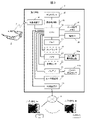
- FIG. 1 is a schematic diagram showing a linked display system in which a mobile terminal 1 and an HMD 2 are connected.
- the HMD 2 is attached to the head of the user U, is wirelessly connected to the mobile terminal 1, and operates in cooperation with each other while transmitting and receiving data and commands.
- the user U can see the image displayed on the display 10 of the mobile terminal 1 and also see the image displayed on the display 30 of the HMD 2.
- a LAN Local Area Network
- a telephone network communication may be used.
- other communication methods such as Bluetooth (registered trademark) for short-range communication and an infrared communication unit may be used, and the method may be selected according to the amount of information to be transmitted.
- FIG. 2 is a diagram showing the appearance of HMD2.
- the HMD 2 worn by the user is composed of parts such as a display 30, a camera 40 (and a microphone), a touch sensor 37, a bone conduction type earphone (audio output unit) 43, a CPU 32, and a battery 42. Details of each component will be described later.
- FIG. 3 is a diagram showing the internal configuration of the mobile terminal 1.
- the mobile terminal 1 will be described, for example, in the case of a smartphone, but other mobile information terminals such as tablet terminals are also applicable.
- the display 10 displays various images and information, and the display control unit 11 controls the display of the display 10.
- the CPU (main control unit) 12 controls the entire operation of the mobile terminal 1, and the memory 13 stores an operation program or the like executed by the CPU 12.
- the data storage memory 14 stores the unique data of the mobile terminal 1.
- the device ID information 15 stores unique device information for identifying the mobile terminal 1.
- the external device IF16 is an interface for inputting / outputting data to / from the HMD2 by wireless connection 9. Connection authentication with the HMD 2 is performed via the external device IF16, and data is transmitted to the mobile terminal 1 to determine whether the HMD 2 is connected to the mobile terminal 1.
- the touch sensor 17 inputs a user's operation to the mobile terminal 1, and can be integrally configured with the display 10.
- the camera 20 has an out-camera that captures an outside view and an in-camera that captures the user U looking at the display 10, and the camera operation abnormality detection unit 20a detects an abnormality in the camera 20.
- the various sensors 21 detect the state (rotation, position, acceleration, etc.) of the mobile terminal 1.
- the battery 22 supplies electric power to the mobile terminal 1, and the battery capacity sensor 22a detects the remaining capacity of the battery 22.
- the user authentication unit 23 identifies the user of the mobile terminal 1, and the external communication unit 24 communicates with an external server (database or the like) via the external network 4.
- FIG. 4 is a diagram showing the internal configuration of HMD2.
- the display 30 can display the image input from the mobile terminal 1 and superimpose and display the image data generated in the HMD 2 and the image taken by the camera 40.
- the display control unit 31 controls the display of the display 30.
- the CPU (main control unit) 32 controls the entire operation of the HMD 2, and the memory 33 stores an operation program or the like executed by the CPU 32.
- the device ID information 35 stores unique device information for identifying the HMD2.
- the external device IF36 transmits / receives data to / from the mobile terminal 1 via a wireless connection 9.
- the touch sensor 37 inputs a user's operation with respect to the HMD2.
- the camera 40 captures the outside view of the HMD2, and the camera operation abnormality detection unit 40a detects the abnormality of the camera 40.
- the various sensors 41 are sensors such as a gyro that measures the position and distance of an object photographed by the camera 40 and measures the movement, acceleration, and rotation of the HMD2.
- the sensor operation abnormality detection unit 41a detects operation abnormalities of various sensors 41.
- the battery 42 supplies power to the HMD 2, and the battery capacity sensor 42a detects the remaining capacity of the battery 7.
- the voice output unit 43 drives a bone conduction type earphone, and the voice output abnormality detection unit 43a detects an operation abnormality of the voice output unit 43.
- FIG. 5 is a diagram showing the types of data input / output between the mobile terminal 1 and the HMD 2 via the external devices IF16 and 36.
- the data output from the mobile terminal 1 to the HMD 2 shown in (a) is measured as a unique ID for identifying the mobile terminal 1, image data for displaying information on the HMD 2, and camera image data input from the HMD 2.
- Image data for displaying an AR (augmented reality) image in consideration of the anteroposterior relationship in the depth direction using distance data, commands for responding to operation input from HMD2, and the like.
- the data output from the HMD 2 to the mobile terminal 1 shown in (b) is a unique ID for identifying the HMD 2, image data taken by the camera 40, and detection data (position, distance, acceleration, rotation, battery) of various sensors 41. Capacity, user authentication, etc.), and operation input data for HMD2 (touch operation, gesture, voice input, etc.).
- ⁇ Operation of mobile terminal> Various applications running on the mobile terminal 1 are stored in the memory 13, and a plurality of application icons that can be selected by the user are displayed on the home screen displayed at startup. Touching these displayed icons will launch the corresponding application.
- the mobile terminal 1 has an operation log display function that can record when, where, which application, which device was used and how, and display it as needed.
- an "operation log application” that displays an “operation log” operated using the mobile terminal 1 and the HMD 2 will be described as an example.
- the "operation log application” for this purpose automatically starts the operation of acquiring the operation log from the time when the mobile terminal 1 is started.
- the data storage memory 14 stores operation logs such as the start time of the application for which the operation instruction is input, the application name, the operation content, the location information, and whether or not the HMD2 is used.
- the operation log information saved in the data storage memory 14 is displayed as a list on the display 10.
- the details of the selected operation log are displayed.
- the operation log information stored in the data storage memory 14 is transmitted to, for example, an external application company 5a via the external communication unit 24 and the network 4, and is used for investigating the usage status of the mobile terminal 1. To. For other applications stored in the mobile terminal 1, information such as usage status is similarly transmitted to the external application company 5b.
- ⁇ Operation of HMD> Various data are transmitted from the mobile terminal 1 to the HMD 2 via the external devices IF16 and 36.
- the operation log information is included in this data, and the operation log information is also displayed on the display 30 of the HMD2.
- the detailed information (lower information and additional information among the hierarchical information) of the item selected by the user by the touch operation in the operation log displayed on the mobile terminal 1 is shared by the HMD2.
- the features of each device (mobile terminal 1 and HMD 2) are utilized to realize an easy-to-see display form.
- the display is shared by the HMD 2. This has the effect of protecting the privacy of the user.
- FIG. 6 is a diagram showing an example of displaying an operation log on the mobile terminal 1.
- the mobile terminal 1 uses an operation log application to record the operation contents of the user.
- FIG. 6 is an example in which the operation contents of one day are displayed in chronological order. For example, if an alarm is sounded by the clock application of the mobile terminal 1 in the first operation of date: November 28, 2019, the operation log is time: 06:05, application (app): clock, operation content: Displays the alarm, address, and unused HMD2 (HMD icon is not displayed). Next, the time: 08:30, the application: SMS (ShortMessageService), the operation content: 5 messages sent and received, and the HMD2 is used (with the HMD icon displayed) are displayed. Similarly, the operation contents are sequentially displayed, and as the final operation of the day, time: 23:30, application: e-book application, operation content: reading, and HMD2 not used (HMD icon is not displayed) are displayed.
- SMS ShortMessageService
- the operation log is displayed on the condition of date: November 28, 2019, but it is also possible to select and set the recorded information such as items other than the date, the number of display matrices, and time.
- FIG. 7 is a diagram showing another display example of the operation log in the mobile terminal 1. While FIG. 6 displays the operation contents for one day, FIG. 7 displays the operation contents for a plurality of days. That is, it is an example in which one day is regarded as one page, a plurality of days are overlapped, and the past operation logs are displayed in a format that can be easily referred to by turning over like a diary.
- the operation log shown in FIGS. 6 and 7 is information related to the operation content, and can display detailed information executed by the operation.
- FIG. 8 is a diagram showing an example of displaying detailed information of the operation log hierarchically. Here, an example is shown in which the date, time, application, operation content, etc. are selected by touching them with a finger and the detailed information is displayed.
- the mobile terminal 1 can display a large amount of information, but for example, when the operation log and the information whose hierarchy is lowered are displayed at the same time, the display area of each becomes smaller. The displayed information becomes difficult to see. Therefore, using HMD2, for example, detailed information in a lower hierarchy is shared and displayed. Since the HMD 2 is a device mounted on the user's head, the character size that can be displayed is smaller and the content is smaller than that of the mobile terminal 1. Therefore, among the operation logs displayed on the mobile terminal 1 described with reference to FIG. 8, detailed information whose hierarchy is lowered by performing the operation of touch 1 is shared and displayed by HMD2.
- FIG. 9 is a diagram showing an example in which the mobile terminal 1 and the HMD 2 are shared and displayed.
- the mobile terminal 1 displays the entire operation log screen as shown in (a)
- the display 30 of the HMD 2 displays detailed information in a lower hierarchy as shown in (b).
- a category of a photo type as shown in FIG. 8 (b) may be displayed, or a plurality of photos included in the category as shown in FIG. 8 (c) may be displayed as thumbnails or photos. Display images in sequence. This makes it easier for the user to see the information as compared with the case where the information is displayed only on the mobile terminal 1.
- the HMD 2 has a feature that the optical system system is different from that of the mobile terminal 1 and it is difficult for others around to see the displayed contents.
- the optical system system is different from that of the mobile terminal 1 and it is difficult for others around to see the displayed contents.
- information for example, a photo
- the user himself / herself can see it, which is also advantageous in terms of privacy protection.
- the amount of information displayed on the mobile terminal 1 is limited, it can be used as a plurality of displays by sharing the display information with the HMD 2, and the usability is improved.
- the operation log is shared and displayed between the mobile terminal 1 and the HMD 2.
- the user can select display items such as photos and SMS message contents in the operation log application settings, and the detailed contents of the operation log displayed on the mobile terminal 1 can be displayed. Is. Further, when there are people around, it is possible to display the selected item on the HMD2 and display the detailed contents of the operation log.
- the display data is transmitted from the mobile terminal 1 to the HMD2 only when the HMD2 is connected to the mobile terminal 1. The operation when there is another person in the vicinity will be described in detail in the third embodiment.
- FIG. 10 is a diagram showing a modified example of the display on the mobile terminal 1. Compared with the display example shown in FIG. 6, only the operations using HMD2 are displayed in the operation log, and the operations not using HMD2 are deleted. For example, an operation log at time: 06:05 (app: clock, operation content: alarm), an operation log at time: 17:30 (app: camera, operation content: 14 photos), displayed in FIG. The operation log (application: electronic book application, operation content: reading) at time: 23:30 does not use HMD2 and is not displayed in FIG. Needless to say, by selecting the operation log for using the HMD displayed here, the details can be displayed as shown in FIG. 8 and can be shared and displayed by the HMD 2 as shown in FIG.
- FIG. 11 is a flowchart showing the operation procedure of the mobile terminal 1.
- the operation of the mobile terminal 1 is started (S100), the operation log application is started, and the operation log display function operated on the mobile terminal 1 is executed (S101).
- the mobile terminal 1 confirms that the data is normally transmitted / received to / from the HMD2 and that the HMD2 is attached to the user by the sensor information (acceleration information or the like) from the HMD2. This connection check is carried out periodically or when an event of the mobile terminal 1 (selection of display items, etc.) occurs. If a connection error is found in the determination of S102, the communication with the HMD2 is terminated and the connection is disconnected (S111).
- the user selects the operation log display method. In this selection, it is selected whether to display the mobile terminal 1 alone (example of FIGS. 6 to 8) or to display the mobile terminal 1 and the HMD 2 in a shared manner (example of FIG. 9) (S103).
- the mobile terminal 1 creates full display data of the operation log summary (displaying the contents of the operation log described in FIG. 6).
- display data of the operation log summary to be displayed on the HMD2 when the HMD2 is used is also created (S104). All the display data of the created operation log summary is displayed on the display 10 of the mobile terminal 1 (S105).
- the detailed display data is created (S107). For example, when the operation log is touched as shown in FIG. 8A (touch 1), the data to be displayed by touch 1 is extracted from the data storage memory 14 and created.
- the display destination is switched so that some display data is displayed on HMD2 (S109). Then, a part of the display data is output to the HMD2 via the external device IF16 (S110). For example, as shown in FIG. 9, the detailed data selected by touch 1 is output to HMD2. The HMD 2 receives this detailed data and displays it on the display 30.
- FIG. 12 is a flowchart showing the operation procedure of HMD2.
- FIG. 9 a case where the operation log is shared and displayed on the HMD 2 will be described.
- the operation of the HMD 2 is started (S200), and the connection with the mobile terminal 1 is checked (S201).
- the camera operation abnormality detection unit 40a and the sensor operation abnormality detection unit 41a check the operation of various parts (camera, sensor, display, etc.) mounted on the HMD2 (S202). Further, the battery capacity sensor 42a checks the remaining amount of the battery 42 of the HMD2 (S203).
- connection error is determined in the determination of S201, the occurrence of an error is displayed on the display 30 (S211). If there is an operation error in any of the parts in the judgment of S202, or if the battery level is low in the judgment of S203, error information is sent to the mobile terminal 1 (S210), and the error information is sent to the display 30 of the HMD2. Display (S211). By outputting the error information to the mobile terminal 1 in S210, the error may be displayed in the HMD 2 in the instruction from the mobile terminal 1 in S211.
- the check result of HMD2 is output to the mobile terminal 1 (S204). Then, the mobile terminal 1 confirms that the HMD 2 is attached to the user, various operations are normal, and the display data output from the mobile terminal 1 can be displayed.
- the HMD2 acquires the display data from the mobile terminal 1 via the external device IF36 (S205). This corresponds to step S110 in FIG.
- the acquired display data is displayed on the display 30 of the HMD 2 (S206). As a result, for example, an image (after touch 1) as shown in FIG. 9B is displayed.
- the information of the item selected in S207 is output to the mobile terminal 1 via the external device IF36 (S208).
- the mobile terminal 1 creates detailed data of the selected item, and the HMD 2 acquires detailed data from the mobile terminal 1 (S209). Then, the process returns to S206, and the acquired detailed data is displayed on the display 30. As a result, for example, a display corresponding to the operation of touch 2 in FIG. 9B is made.
- the "operation log" used in the above explanation is hierarchical information, and is a suitable example for explaining the operation of reading the information in the lower hierarchy. That is, the operation log is configured by recording information such as the location at that time and the linked device in chronological order regarding the instruction operation from the user performed on the mobile terminal.
- the operation log that the information displayed by the mobile terminal and the HMD is shared.
- the operation log For example, when displaying a book on a mobile terminal and reading it, displaying the meaning of an unknown word on the HMD, or displaying a map on the mobile terminal, about a specific place in it. It can also be applied when displaying the detailed information of the above on the HMD.
- additional information can be shared and displayed by the HMD so as not to disturb the screen of the mobile terminal.
- the mobile terminal and the HMD cooperate to form the display screen.
- the HMD is treated like a sub screen of the mobile terminal, and information that cannot be displayed on the screen of the mobile terminal or information that is hierarchically lower is displayed on the HMD side. Therefore, the display content of the mobile terminal is retained as it is, and the content can be confirmed by looking at the mobile terminal, and more detailed information can be viewed at the same time by the HMD. As a result, it is possible to realize an easy-to-use operation and an easy-to-see display form by utilizing the characteristics of each device.
- the first embodiment a method of using the touch sensors 17 and 37 of the mobile terminal 1 and the HMD 2 to select the corresponding item when it is desired to display the detailed contents of the displayed operation log has been described.
- a camera is often mounted on a general mobile terminal 1 or HMD2. Therefore, in the second embodiment, a method of detecting the line of sight of the user using this camera and selecting an item (hereinafter, referred to as “line-of-sight touch”) will be described.
- FIG. 13 is a diagram illustrating a line-of-sight touch using the camera 20 of the mobile terminal 1.
- the line-of-sight touch detects which item the user's eyeball direction (line of sight) is looking at and selects that item.
- (A) is a state in which the user U is looking at the display screen of the mobile terminal 1.
- the camera (in-camera) 20 mounted on the mobile terminal 1 is used to detect which position (which item) the user U's line of sight is looking at on the display screen, that is, where the line of sight is.
- FIG. (B) shows an example of the screen of the mobile terminal 1.
- five cross points (X1 to X5) are displayed one after another on the screen of the mobile terminal 1 at predetermined time intervals.
- the user looks at the displayed cross points in order according to the instruction from the mobile terminal 1.
- the direction of the eyeball at that time that is, the line-of-sight direction is detected by the camera 20 of the mobile terminal 1, and the reference position and angle of the user's line of sight are obtained from the line-of-sight directions to the five cross points.
- the difference in position and orientation of the pupil and the iris of the eyeball when gazing at X4 and X5 at the lower end of the screen is detected with reference to the time when X1 in the center of the screen is gazed. Further, in the same method, the difference in position and orientation when gazing at the center and the left and right edges is detected, and these detected values are stored in the data storage memory 14.
- (C) is a state in which the user U actually gazes at a certain position on the screen.
- the current user's line-of-sight position is calculated by comparing the user's line-of-sight position (the position of the face and the position and direction of the pupil and the iris of the eyeball) captured by the camera 20 with the line-of-sight position with respect to the cross point which is the reference position. Then, a marker M indicating the gazing point of the user's line of sight is displayed at the calculated position on the screen.
- the values of the angle, position, and distance between the mobile terminal 1 and the face and eyeball of the user U are important.
- the above-mentioned reference direction of the line of sight is the fluctuation (accuracy) of the angle, position, and distance between the mobile terminal 1 and the face, eyeball, pupil, and iris, and the camera 20 and distance sensor 21 of the mobile terminal 1. It is necessary to check with such as and correct it.
- FIG. 14 is a diagram showing an example of a user's face image (user image) taken by the camera (in-camera) 20 of the mobile terminal 1.
- A is a state in which the user U gazes at the reference position (cross point X1 in FIG. 13) in the screen. From this image, the line-of-sight direction of the user U is obtained and used as a reference value.
- (b) is a state in which the user U is currently gazing at a desired position (selected position) in the screen.
- the gaze position changes, the image of the user U, particularly the position, angle, and the like of the user's face and eyeball change.
- the gaze image (b) at the selected position has a smaller face size and is farther away than the gaze image (a) at the reference position. Further, the center position of the eye is shifted downward as shown by the broken line L1 ⁇ L2. The distance to the face may be detected by the distance sensor 21 instead of the difference in the camera image.
- the measured values of the positions and distances of the face and the eyeball obtained from the gaze image of the selected position in (b) were obtained when the five cross points (X1 to X5) in FIG. 13 (a) were gaze.
- the position in the screen that the user is currently gazing at can be calculated by calculating and correcting the difference amount based on the measured value. That is, it is possible to detect which position on the screen the user is gazing at by using the camera 20 of the mobile terminal 1.
- FIG. 15 is a flowchart showing an operation procedure of the line-of-sight touch using the camera 20 of the mobile terminal 1.
- the operation of the mobile terminal 1 is started (S300), and the line-of-sight touch application is started (S301).
- the initial setting of the line-of-sight touch is started (S302).
- An image for initial setting of line-of-sight touch is displayed on the display 10 of the mobile terminal 1 (S303). For example, the cross points X1 to X5 as shown in FIG. 13A are sequentially displayed.
- the user sequentially gazes at the image (cross point) displayed on the display 10 via the attached HMD2 (S304).
- the camera 20 mounted on the mobile terminal 1 acquires an image of the eyeball of the user who is gazing (S305).
- the reference value in the line-of-sight direction is calculated and used as the initial position of the line-of-sight touch (S306).
- the calculation result of the line-of-sight position when each cross point X1 to X5 is sequentially gazed is saved together with the information of the initial position of the line-of-sight touch.
- the positional relationship (angle, position, distance) between the mobile terminal 1 and the eyeball at this time is acquired by the sensor 21 of the mobile terminal 1. Further, when the HMD 2 is attached, the distance information to the mobile terminal 1 and the position and direction of the pupil and the iris of the eyeball are also acquired by the eye tracking camera (S307).
- the initial position calculated in S306 and the positional relationship information between the mobile terminal 1 and the eyeball when gazing at each cross point acquired in S307 are linked to the device ID 35 of the HMD2 and the user information of the mobile terminal 1. It is saved in the data storage memory 14 (S308).
- the camera 20 mounted on the mobile terminal 1 acquires an image of the eyeball of the user who is gazing (S311).
- the user's line-of-sight direction is obtained from the acquired user image information, and the user's gaze point is calculated by comparing with the positional relationship information at the time of gaze at each point stored in the data storage memory 14 in S308 (calculating the difference). (S312).
- the position of the gazing point that is, the line-of-sight touch position is displayed with a marker on the screen of the mobile terminal 1 (S313). If the gazing point stays at the position where the marker is displayed for a certain period of time or longer, the same operation as clicking or touching the position where the marker exists is performed.
- the distance between the mobile terminal 1 and the face, the angle with the eyeball, the position, the distance, etc. are constantly checked, and if there is a change, the face or eyeball from the reference point is checked. It is necessary to correct the change in the line-of-sight position due to the change in. Therefore, based on the initial setting position, the angle, position, distance, etc. between the mobile terminal and the face and eyeball are constantly monitored, and when a deviation of a certain amount or more occurs, the movement range of the line of sight obtained in the initial setting is used. Correct the deviation based on the calculated value.
- This line-of-sight touch correction is a deviation that can be corrected by displaying an icon often used in the application such as the operation log end icon at a fixed position as a mark and checking whether the icon is accurately grasped at a certain frequency. Make corrections.
- the line-of-sight touch operation can also be performed using the camera 40 mounted on the HMD2. This will be described below.
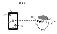
- FIG. 16 is a diagram illustrating a line-of-sight touch using the camera 40 of the HMD2.
- an image of reference cross points X1 to X3 is displayed on the screen of the mobile terminal 1, for example, as shown in FIG.
- point X1 is displayed in the center of the screen
- point X2 is displayed in the upper left corner of the screen
- point X3 is displayed in the lower right corner of the screen.
- the user U gazes at these displayed cross points according to the instructions of the mobile terminal 1, and takes a picture with the camera 40 of the HMD 2. Then, the image taken by the camera 40 is sent to the mobile terminal 1.
- the reference center position is obtained from the acquired camera image of each cross point. For example, the position of the cross point X1 in the center of the screen and the average value of the positions of the cross points X2 and X3 in the corner of the screen are compared, and if they are approximately the same position, they are set as the reference position for the line-of-sight touch.
- the HMD2 in order to detect the position and angle of the pupil and the iris of the eyeball, if the HMD2 is equipped with an eye tracking camera, that information may be used. In detecting the line of sight, the angle, position, and distance between the mobile terminal 1 and the HMD2, the position and angle of the HMD2 itself with the eyeball (position and angle when mounted on the head), and the like are important.
- FIG. 17 is a diagram showing an example of an image of the mobile terminal 1 taken by the camera 40 of the HMD 2.
- the gaze point of the user U with respect to the screen of the mobile terminal 1 is detected from the image of the mobile terminal 1 (referred to as “terminal image” here) taken by the camera 40 of the HMD2.
- terminal image the image of the mobile terminal 1 taken by the camera 40 of the HMD2.
- the image is taken as in the terminal image 1 of (a)
- the entire screen of the mobile terminal 1 is visible, and information for detecting which point the user is gazing at is acquired. Yes, it's appropriate.
- the HMD 2 gives an instruction to move closer to the mobile terminal 1.
- the terminal image 5 of (e) captures the entire screen of the mobile terminal 1 to the full limit, and indicates that the terminal image 5 is in a position where it cannot be approached any more. In this way, the mobile terminal 1 is adjusted so as to be photographed in the state of the terminal image 1 of (a).
- FIG. 18 is a diagram showing an example of obtaining a viewpoint position from a terminal image taken by the camera 40 of the HMD2.
- (A) shows the case where the reference position of the screen of the mobile terminal 1 is obtained, and
- (b) shows the case where the viewpoint position of the user is obtained from the actually acquired terminal image.
- the distance and angle of the HMD2 with respect to the screen of the mobile terminal 1 are detected by the three cross droppers X1 to X3, and the reference position is obtained. It is detected what kind of difference the terminal image of (b) has with respect to the numerical value at that time.
- the terminal image of (b) since the center of the screen (cross point X1) is in the center of the range photographed by the HMD2, it can be seen that the mobile terminal 1 is substantially in front of the HMD2. Further, since the screen of the mobile terminal 1 is displayed in a large size, it can be seen that the distance to the HMD 2 is closer than that at the time of taking the terminal image of (a).
- the tilted state can be detected by detecting the position information of the four corners of the screen of the mobile terminal 1. Then, it becomes possible to detect in (b) which part of the screen of the mobile terminal 1 is gazing at the gaze point position obtained by setting the reference position in (a). If the HMD2 is equipped with an eye tracking camera and can measure the position and orientation of the pupil and iris of the eyeball, using these as parameters will improve the accuracy of finding the gaze point.
- FIG. 19 is a flowchart showing the operation procedure of the line-of-sight touch using the camera 40 of the HMD2.
- the operation of HMD2 is started (S400), the line-of-sight touch application is started, and a command to start the application is also sent to the mobile terminal 1 (S401).
- the initial setting of the line-of-sight touch is started (S402).
- an image (cross point) for initial setting of line-of-sight touch is displayed on the display 10 (S403). For example, the cross points X1 to X3 as shown in FIG. 16 are displayed.
- the camera 40 mounted on the HMD2 captures an image of the mobile terminal 1 that the user is gazing at, and sends the image from the external device IF36 to the mobile terminal 1.
- the mobile terminal 1 acquires an image (terminal image) of the mobile terminal taken by the HMD 2 (S405).
- the position and angle of the HMD 2 are calculated from the position of the displayed image and the terminal image taken by the HMD 2, and the reference position of the line-of-sight touch is set (S406).
- the user is instructed to correct the holding position of the mobile terminal 1.
- the angle and position information between the mobile terminal 1 and the HMD 2 and the angle information of the pupil and the iris of the eyeball are acquired by the eye tracking camera mounted on the HMD 2 (S407).
- the initial position calculated in S406, the angle between the mobile terminal 1 and the HMD2 acquired in S407, and the position information are linked with the device ID 35 of the HMD2 and the user information, and stored in the data storage memory 14 (S408). This completes the initial setting (S409).
- the camera 40 mounted on the HMD 2 acquires an image (terminal image) of the mobile terminal 1 being watched and sends it to the mobile terminal (S411).
- the mobile terminal 1 compares the acquired terminal image with the angle and position information of the HMD2 stored in the data storage memory 14 in S408, and calculates where on the screen of the mobile terminal 1 the mobile terminal 1 is gazing. (S412).
- the position of the gazing point that is, the line-of-sight touch position is displayed with a marker on the screen of the mobile terminal 1 (S413). If the gazing point stays at the position where the marker is displayed for a certain period of time or longer, the same operation as clicking or touching the position where the marker exists is performed.
- the distance and angle between the mobile terminal and the HMD, the angle of the HMD itself when the user wears it, etc. are constantly monitored, and if a deviation of a certain amount or more appears, the deviation is corrected. do.
- the image taken by the camera 40 of the HMD2 is sent to the mobile terminal 1 and the distance and the angle are obtained on the mobile terminal 1 side. You may go on the external server via.
- the user can select a desired display item and display detailed information about the selected item simply by gazing at the display screen of the mobile terminal. Therefore, the convenience of user operation for switching the display contents is improved.
- the HMD2 has an advantage that it is out of focus on the lens of the glasses, which is the display surface, due to the difference in the optical system method, and it is difficult for the surrounding people to see what is being displayed. Therefore, in the third embodiment, in consideration of privacy, a configuration for positively using and displaying the HMD 2 will be described.
- the acquired operation log information is displayed by appropriately switching between the mobile terminal 1 and the HMD 2. Then, in order to prevent the operation log to be displayed from being seen by people around, a "peep prevention function" is added. With the “peep prevention function", the operation log information is hidden on the mobile terminal 1 and displayed on the HMD 2 in an environment where the operation log is easily peeked or when it is not desired to be shown.
- the “peep prevention function” may be automatically implemented or may be selected and implemented by the user.
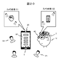
- FIG. 20 is a diagram illustrating a configuration for automatically implementing the peep prevention function.
- the user U is in a state of wearing the HMD 2 and looking at the display screen of the mobile terminal 1. There is a possibility that another person Un is in the vicinity of the user U and the screen of the mobile terminal 1 is being peeped.
- the camera 20 mounted on the mobile terminal 1 (however, the in-camera that captures the user U side) captures an image of the user's surroundings when the mobile terminal 1 is used. If a person Un other than the user U is shown in the captured camera image C1, it is determined that there is a possibility of being peeped. At this time, the camera 40 of the HMD2 may be used to capture an image of the front of the user, and it may be detected whether or not there is a person Un who may be peeping in the captured camera image C2.
- the cameras 20 and 40 for shooting are equipped with a wide-angle lens.
- the degree of wide angle is required to be equal to or greater than the viewing angle at which the display 10 of the mobile terminal 1 can be seen from the surroundings.
- the direction of the face of a person Un other than the photographed user U is detected, the angle of the mobile terminal 1 with the display 10 is detected, and if the viewing angle of the display 10 or more is exceeded, the possibility of peeping is possible. It can be judged to be low.
- the cameras 20 and 40 are always operated or continuously operated at regular intervals, unintended camera shooting may occur, and conversely, it is necessary to consider the privacy of others. Therefore, it is necessary to clearly indicate on the mobile terminal 1 or the like that the camera is operating or the peep prevention function is operating. For example, it is desirable to turn on the lamp of the mobile terminal 1 to clearly indicate it.
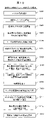
- FIG. 21 shows a flowchart when the peep prevention function is automatically implemented.
- the operation of the mobile terminal 1 is started (S500), the operation log application is started, and the operation log display function operated on the mobile terminal 1 is executed (S501).
- Authenticate the user S502 and check the connection with HMD2 (S503). If a connection error occurs, the communication with HMD2 is terminated and the connection is disconnected.
- the camera 20 of the mobile terminal 1 captures an image of the user's surroundings.
- the camera 40 of the HMD 2 may take an image of the periphery of the mobile terminal 1 (S506).
- the presence or absence of a person other than the user is determined from the captured camera image. Further, it is determined whether or not there is a possibility of peeping from the angle between the photographed person and the display 10 of the mobile terminal 1 (S507).
- the display of the operation log on the mobile terminal 1 is stopped and the display is performed only on the HMD 2 (S508). Further, even if there is an operation (selection) for displaying more detailed information with respect to the operation log information displayed on the HMD2, the detailed information is displayed only on the HMD2.
- the operation log is displayed on the mobile terminal 1 as it is, or using both the mobile terminal 1 and the HMD 2 (S509).
- FIG. 22 shows a flowchart when the user selects and implements the peep prevention function.
- the operation of the mobile terminal 1 is started (S600), the operation log application is started, and the operation log display function operated on the mobile terminal 1 is executed (S601).
- the connection between the mobile terminal 1 and the HMD 2 is checked (S602).
- the user selects the setting (ON / OFF) of the "peep prevention function” (S603).
- the sensor 21 (accelerometer) of the mobile terminal 1 determines whether the user is moving or stationary (S604). When the user is moving, the process proceeds to S607.
- the user determines the setting state of the "peep prevention function" of the mobile terminal 1 (S605). If it is not set (S605, Off), the process proceeds to S607.
- the display of the operation log on the mobile terminal 1 is stopped and the display is performed only on the HMD 2 (S606). Further, even if there is an operation (selection) for displaying more detailed information with respect to the operation log information displayed on the HMD2, the detailed information is displayed only on the HMD2.
- the user since the user is moving and there is little possibility of being peeped by people around him, and the user has not selected the peeping prevention function, he / she can use the mobile terminal 1 as it is, or the mobile terminals 1 and HMD2. Display the operation log using both.
- the peep prevention function described above is not limited to displaying the operation log, but can be applied to the display of various information.
- the information that is not desired to be seen by others is displayed only on the HMD, so that the user's privacy is not peeped by the people around the mobile terminal. Has the effect of protecting.
- HMD Head-mounted display
- 10 Display
- 11 Display control unit
- 12 CPU (main control unit)
- 14 Data storage memory
- 16, 36 External device IF (interface)
- 17, 37 Touch sensor
- 20, 40 Camera, 21, 41: Various sensors.
Landscapes
- Engineering & Computer Science (AREA)
- Theoretical Computer Science (AREA)
- General Engineering & Computer Science (AREA)
- Physics & Mathematics (AREA)
- General Physics & Mathematics (AREA)
- Human Computer Interaction (AREA)
- Computer Vision & Pattern Recognition (AREA)
- Optics & Photonics (AREA)
- User Interface Of Digital Computer (AREA)
- Position Input By Displaying (AREA)
Priority Applications (6)
| Application Number | Priority Date | Filing Date | Title |
|---|---|---|---|
| US18/030,615 US12056417B2 (en) | 2020-10-09 | 2020-10-09 | Portable terminal, head mounted display, and cooperative display system that connects the portable terminal and the head mounted display to display information by cooperation between the portable terminal and the head mounted display |
| JP2022555220A JP7578709B2 (ja) | 2020-10-09 | 2020-10-09 | 携帯端末とヘッドマウントディスプレイ及びその連携表示システム |
| CN202080105982.4A CN116324740A (zh) | 2020-10-09 | 2020-10-09 | 便携终端和头戴式显示器及其协作显示系统 |
| PCT/JP2020/038271 WO2022074815A1 (ja) | 2020-10-09 | 2020-10-09 | 携帯端末とヘッドマウントディスプレイ及びその連携表示システム |
| US18/761,429 US12578914B2 (en) | 2020-10-09 | 2024-07-02 | Portable terminal that is connected to a headmounted display to display information in cooperation |
| JP2024187144A JP7822443B2 (ja) | 2020-10-09 | 2024-10-24 | 携帯端末とヘッドマウントディスプレイ及びその連携表示システム |
Applications Claiming Priority (1)
| Application Number | Priority Date | Filing Date | Title |
|---|---|---|---|
| PCT/JP2020/038271 WO2022074815A1 (ja) | 2020-10-09 | 2020-10-09 | 携帯端末とヘッドマウントディスプレイ及びその連携表示システム |
Related Child Applications (2)
| Application Number | Title | Priority Date | Filing Date |
|---|---|---|---|
| US18/030,615 A-371-Of-International US12056417B2 (en) | 2020-10-09 | 2020-10-09 | Portable terminal, head mounted display, and cooperative display system that connects the portable terminal and the head mounted display to display information by cooperation between the portable terminal and the head mounted display |
| US18/761,429 Continuation US12578914B2 (en) | 2020-10-09 | 2024-07-02 | Portable terminal that is connected to a headmounted display to display information in cooperation |
Publications (1)
| Publication Number | Publication Date |
|---|---|
| WO2022074815A1 true WO2022074815A1 (ja) | 2022-04-14 |
Family
ID=81126397
Family Applications (1)
| Application Number | Title | Priority Date | Filing Date |
|---|---|---|---|
| PCT/JP2020/038271 Ceased WO2022074815A1 (ja) | 2020-10-09 | 2020-10-09 | 携帯端末とヘッドマウントディスプレイ及びその連携表示システム |
Country Status (4)
| Country | Link |
|---|---|
| US (2) | US12056417B2 (https=) |
| JP (2) | JP7578709B2 (https=) |
| CN (1) | CN116324740A (https=) |
| WO (1) | WO2022074815A1 (https=) |
Families Citing this family (2)
| Publication number | Priority date | Publication date | Assignee | Title |
|---|---|---|---|---|
| WO2023053557A1 (ja) * | 2021-09-30 | 2023-04-06 | 富士フイルム株式会社 | 情報処理装置、情報処理方法、及びプログラム |
| CN119718061B (zh) * | 2023-09-27 | 2025-12-09 | 珠海莫界科技有限公司 | 智能穿戴设备与移动终端的交互方法、装置、设备及介质 |
Citations (6)
| Publication number | Priority date | Publication date | Assignee | Title |
|---|---|---|---|---|
| JP2005346609A (ja) * | 2004-06-07 | 2005-12-15 | National Institute Of Information & Communication Technology | Webページ情報融合表示装置、Webページ情報融合表示方法、Webページ情報融合表示プログラムおよびそのプログラムを記録したコンピュータ読み取り可能な記録媒体 |
| JP2012002568A (ja) * | 2010-06-15 | 2012-01-05 | Brother Ind Ltd | ナビゲーションシステム、携帯機器及び携帯機器用プログラム |
| JP2012044429A (ja) * | 2010-08-18 | 2012-03-01 | Brother Ind Ltd | 画像表示システム、及び画像表示システムに含まれる携帯型情報処理装置のためのコンピュータプログラム |
| JP2014086063A (ja) * | 2012-10-29 | 2014-05-12 | Kyocera Corp | 電子機器、視線入力プログラムおよび視線入力方法 |
| JP2014153889A (ja) * | 2013-02-07 | 2014-08-25 | Sharp Corp | 制御装置、携帯端末、および制御プログラム |
| WO2020003361A1 (ja) * | 2018-06-25 | 2020-01-02 | マクセル株式会社 | ヘッドマウントディスプレイ、ヘッドマウントディスプレイ連携システム及びその方法 |
Family Cites Families (7)
| Publication number | Priority date | Publication date | Assignee | Title |
|---|---|---|---|---|
| JPH10240491A (ja) * | 1997-02-26 | 1998-09-11 | Olympus Optical Co Ltd | 情報処理装置 |
| US9466266B2 (en) * | 2013-08-28 | 2016-10-11 | Qualcomm Incorporated | Dynamic display markers |
| US9858720B2 (en) * | 2014-07-25 | 2018-01-02 | Microsoft Technology Licensing, Llc | Three-dimensional mixed-reality viewport |
| US10031648B2 (en) * | 2014-12-31 | 2018-07-24 | Trading Technologies International, Inc. | Systems and methods to obfuscate market data on a trading device |
| JP6534292B2 (ja) * | 2015-04-24 | 2019-06-26 | パナソニック インテレクチュアル プロパティ コーポレーション オブ アメリカPanasonic Intellectual Property Corporation of America | ヘッドマウントディスプレイ、及び、ヘッドマウントディスプレイの制御方法 |
| JPWO2017138153A1 (ja) | 2016-02-12 | 2018-11-22 | 富士通株式会社 | 端末装置、管理方法、制御方法、管理プログラム、及び制御プログラム |
| TWI678642B (zh) * | 2017-12-07 | 2019-12-01 | 宏碁股份有限公司 | 顯示裝置及其防窺方法 |
-
2020
- 2020-10-09 CN CN202080105982.4A patent/CN116324740A/zh active Pending
- 2020-10-09 US US18/030,615 patent/US12056417B2/en active Active
- 2020-10-09 WO PCT/JP2020/038271 patent/WO2022074815A1/ja not_active Ceased
- 2020-10-09 JP JP2022555220A patent/JP7578709B2/ja active Active
-
2024
- 2024-07-02 US US18/761,429 patent/US12578914B2/en active Active
- 2024-10-24 JP JP2024187144A patent/JP7822443B2/ja active Active
Patent Citations (6)
| Publication number | Priority date | Publication date | Assignee | Title |
|---|---|---|---|---|
| JP2005346609A (ja) * | 2004-06-07 | 2005-12-15 | National Institute Of Information & Communication Technology | Webページ情報融合表示装置、Webページ情報融合表示方法、Webページ情報融合表示プログラムおよびそのプログラムを記録したコンピュータ読み取り可能な記録媒体 |
| JP2012002568A (ja) * | 2010-06-15 | 2012-01-05 | Brother Ind Ltd | ナビゲーションシステム、携帯機器及び携帯機器用プログラム |
| JP2012044429A (ja) * | 2010-08-18 | 2012-03-01 | Brother Ind Ltd | 画像表示システム、及び画像表示システムに含まれる携帯型情報処理装置のためのコンピュータプログラム |
| JP2014086063A (ja) * | 2012-10-29 | 2014-05-12 | Kyocera Corp | 電子機器、視線入力プログラムおよび視線入力方法 |
| JP2014153889A (ja) * | 2013-02-07 | 2014-08-25 | Sharp Corp | 制御装置、携帯端末、および制御プログラム |
| WO2020003361A1 (ja) * | 2018-06-25 | 2020-01-02 | マクセル株式会社 | ヘッドマウントディスプレイ、ヘッドマウントディスプレイ連携システム及びその方法 |
Also Published As
| Publication number | Publication date |
|---|---|
| US20230367536A1 (en) | 2023-11-16 |
| JP7578709B2 (ja) | 2024-11-06 |
| JP7822443B2 (ja) | 2026-03-02 |
| JP2025017368A (ja) | 2025-02-05 |
| JPWO2022074815A1 (https=) | 2022-04-14 |
| US12578914B2 (en) | 2026-03-17 |
| CN116324740A (zh) | 2023-06-23 |
| US20240354048A1 (en) | 2024-10-24 |
| US12056417B2 (en) | 2024-08-06 |
Similar Documents
| Publication | Publication Date | Title |
|---|---|---|
| EP3540571B1 (en) | Method and device for editing virtual scene, and non-transitory computer-readable storage medium | |
| JP6940702B2 (ja) | ヘッドマウントディスプレイ、ヘッドマウントディスプレイ連携システム及びその方法 | |
| JP7822443B2 (ja) | 携帯端末とヘッドマウントディスプレイ及びその連携表示システム | |
| KR102482361B1 (ko) | 원격 디바이스로부터의 직접 입력 | |
| CN108833607B (zh) | 物理地址获取方法、装置及可读介质 | |
| EP2797299B1 (en) | Device and method for remote controlling of an external display using different positions of the remote controller | |
| JP7799787B2 (ja) | メガネ型情報機器、その方法及びプログラム | |
| EP3076382B1 (en) | Method, apparatus and electronic device for display control | |
| US20170038838A1 (en) | Information processing system and information processing method | |
| JP7073122B2 (ja) | 電子機器、制御方法及びプログラム | |
| WO2014022905A1 (en) | Stacked device position identification | |
| US11137600B2 (en) | Display device, display control method, and display system | |
| JP2020035293A (ja) | 電子機器及び制御方法 | |
| JPWO2019176009A1 (ja) | 携帯情報端末 | |
| US11842119B2 (en) | Display system that displays virtual object, display device and method of controlling same, and storage medium | |
| WO2021166238A1 (ja) | 情報表示装置 | |
| CN106886287B (zh) | 用于在虚拟现实设备中共享画面的方法和装置 | |
| JP2019133387A (ja) | 電子機器、ウェアラブル機器および文字入力制御方法 | |
| CN110333888B (zh) | 功能更新方法、装置、设备及存储介质 | |
| JP7034856B2 (ja) | 電子機器、制御プログラム及び表示制御方法 | |
| KR102218994B1 (ko) | 단말 장치, 데이터 처리 시스템, 컴퓨터 판독 가능한 매체 및 데이터 처리 방법 | |
| WO2014178477A1 (ko) | 헤드 마운트 디스플레이 및 이를 이용한 콘텐츠 제공 방법 | |
| KR20160027813A (ko) | 글래스형 단말기 | |
| JP6995651B2 (ja) | 電子機器、ウェアラブル機器および表示制御方法 | |
| HK40071928A (en) | Method and apparatus for displaying identity information, terminal, server and storage medium |
Legal Events
| Date | Code | Title | Description |
|---|---|---|---|
| 121 | Ep: the epo has been informed by wipo that ep was designated in this application |
Ref document number: 20956762 Country of ref document: EP Kind code of ref document: A1 |
|
| ENP | Entry into the national phase |
Ref document number: 2022555220 Country of ref document: JP Kind code of ref document: A |
|
| NENP | Non-entry into the national phase |
Ref country code: DE |
|
| 122 | Ep: pct application non-entry in european phase |
Ref document number: 20956762 Country of ref document: EP Kind code of ref document: A1 |