WO2022071441A1 - 転写シート及びこれを利用した樹脂成形品の製造方法 - Google Patents
転写シート及びこれを利用した樹脂成形品の製造方法 Download PDFInfo
- Publication number
- WO2022071441A1 WO2022071441A1 PCT/JP2021/035985 JP2021035985W WO2022071441A1 WO 2022071441 A1 WO2022071441 A1 WO 2022071441A1 JP 2021035985 W JP2021035985 W JP 2021035985W WO 2022071441 A1 WO2022071441 A1 WO 2022071441A1
- Authority
- WO
- WIPO (PCT)
- Prior art keywords
- layer
- transfer
- resin
- meth
- acrylate
- Prior art date
- Legal status (The legal status is an assumption and is not a legal conclusion. Google has not performed a legal analysis and makes no representation as to the accuracy of the status listed.)
- Ceased
Links
Images


Classifications
-
- B—PERFORMING OPERATIONS; TRANSPORTING
- B44—DECORATIVE ARTS
- B44C—PRODUCING DECORATIVE EFFECTS; MOSAICS; TARSIA WORK; PAPERHANGING
- B44C1/00—Processes, not specifically provided for elsewhere, for producing decorative surface effects
- B44C1/16—Processes, not specifically provided for elsewhere, for producing decorative surface effects for applying transfer pictures or the like
- B44C1/165—Processes, not specifically provided for elsewhere, for producing decorative surface effects for applying transfer pictures or the like for decalcomanias; sheet material therefor
- B44C1/17—Dry transfer
- B44C1/1712—Decalcomanias applied under heat and pressure, e.g. provided with a heat activable adhesive
-
- B—PERFORMING OPERATIONS; TRANSPORTING
- B29—WORKING OF PLASTICS; WORKING OF SUBSTANCES IN A PLASTIC STATE IN GENERAL
- B29C—SHAPING OR JOINING OF PLASTICS; SHAPING OF MATERIAL IN A PLASTIC STATE, NOT OTHERWISE PROVIDED FOR; AFTER-TREATMENT OF THE SHAPED PRODUCTS, e.g. REPAIRING
- B29C45/00—Injection moulding, i.e. forcing the required volume of moulding material through a nozzle into a closed mould; Apparatus therefor
- B29C45/14—Injection moulding, i.e. forcing the required volume of moulding material through a nozzle into a closed mould; Apparatus therefor incorporating preformed parts or layers, e.g. injection moulding around inserts or for coating articles
- B29C45/1418—Injection moulding, i.e. forcing the required volume of moulding material through a nozzle into a closed mould; Apparatus therefor incorporating preformed parts or layers, e.g. injection moulding around inserts or for coating articles the inserts being deformed or preformed, e.g. by the injection pressure
-
- B—PERFORMING OPERATIONS; TRANSPORTING
- B29—WORKING OF PLASTICS; WORKING OF SUBSTANCES IN A PLASTIC STATE IN GENERAL
- B29C—SHAPING OR JOINING OF PLASTICS; SHAPING OF MATERIAL IN A PLASTIC STATE, NOT OTHERWISE PROVIDED FOR; AFTER-TREATMENT OF THE SHAPED PRODUCTS, e.g. REPAIRING
- B29C45/00—Injection moulding, i.e. forcing the required volume of moulding material through a nozzle into a closed mould; Apparatus therefor
- B29C45/14—Injection moulding, i.e. forcing the required volume of moulding material through a nozzle into a closed mould; Apparatus therefor incorporating preformed parts or layers, e.g. injection moulding around inserts or for coating articles
- B29C45/14688—Coating articles provided with a decoration
-
- B—PERFORMING OPERATIONS; TRANSPORTING
- B29—WORKING OF PLASTICS; WORKING OF SUBSTANCES IN A PLASTIC STATE IN GENERAL
- B29C—SHAPING OR JOINING OF PLASTICS; SHAPING OF MATERIAL IN A PLASTIC STATE, NOT OTHERWISE PROVIDED FOR; AFTER-TREATMENT OF THE SHAPED PRODUCTS, e.g. REPAIRING
- B29C45/00—Injection moulding, i.e. forcing the required volume of moulding material through a nozzle into a closed mould; Apparatus therefor
- B29C45/14—Injection moulding, i.e. forcing the required volume of moulding material through a nozzle into a closed mould; Apparatus therefor incorporating preformed parts or layers, e.g. injection moulding around inserts or for coating articles
- B29C45/14754—Injection moulding, i.e. forcing the required volume of moulding material through a nozzle into a closed mould; Apparatus therefor incorporating preformed parts or layers, e.g. injection moulding around inserts or for coating articles being in movable or releasable engagement with the coating, e.g. bearing assemblies
-
- B—PERFORMING OPERATIONS; TRANSPORTING
- B29—WORKING OF PLASTICS; WORKING OF SUBSTANCES IN A PLASTIC STATE IN GENERAL
- B29C—SHAPING OR JOINING OF PLASTICS; SHAPING OF MATERIAL IN A PLASTIC STATE, NOT OTHERWISE PROVIDED FOR; AFTER-TREATMENT OF THE SHAPED PRODUCTS, e.g. REPAIRING
- B29C45/00—Injection moulding, i.e. forcing the required volume of moulding material through a nozzle into a closed mould; Apparatus therefor
- B29C45/14—Injection moulding, i.e. forcing the required volume of moulding material through a nozzle into a closed mould; Apparatus therefor incorporating preformed parts or layers, e.g. injection moulding around inserts or for coating articles
- B29C45/14827—Injection moulding, i.e. forcing the required volume of moulding material through a nozzle into a closed mould; Apparatus therefor incorporating preformed parts or layers, e.g. injection moulding around inserts or for coating articles using a transfer foil detachable from the insert
-
- B—PERFORMING OPERATIONS; TRANSPORTING
- B29—WORKING OF PLASTICS; WORKING OF SUBSTANCES IN A PLASTIC STATE IN GENERAL
- B29C—SHAPING OR JOINING OF PLASTICS; SHAPING OF MATERIAL IN A PLASTIC STATE, NOT OTHERWISE PROVIDED FOR; AFTER-TREATMENT OF THE SHAPED PRODUCTS, e.g. REPAIRING
- B29C45/00—Injection moulding, i.e. forcing the required volume of moulding material through a nozzle into a closed mould; Apparatus therefor
- B29C45/14—Injection moulding, i.e. forcing the required volume of moulding material through a nozzle into a closed mould; Apparatus therefor incorporating preformed parts or layers, e.g. injection moulding around inserts or for coating articles
- B29C45/14688—Coating articles provided with a decoration
- B29C2045/14721—Coating articles provided with a decoration decorations transferred by diffusion or sublimation
-
- B—PERFORMING OPERATIONS; TRANSPORTING
- B29—WORKING OF PLASTICS; WORKING OF SUBSTANCES IN A PLASTIC STATE IN GENERAL
- B29C—SHAPING OR JOINING OF PLASTICS; SHAPING OF MATERIAL IN A PLASTIC STATE, NOT OTHERWISE PROVIDED FOR; AFTER-TREATMENT OF THE SHAPED PRODUCTS, e.g. REPAIRING
- B29C45/00—Injection moulding, i.e. forcing the required volume of moulding material through a nozzle into a closed mould; Apparatus therefor
- B29C45/14—Injection moulding, i.e. forcing the required volume of moulding material through a nozzle into a closed mould; Apparatus therefor incorporating preformed parts or layers, e.g. injection moulding around inserts or for coating articles
- B29C45/14754—Injection moulding, i.e. forcing the required volume of moulding material through a nozzle into a closed mould; Apparatus therefor incorporating preformed parts or layers, e.g. injection moulding around inserts or for coating articles being in movable or releasable engagement with the coating, e.g. bearing assemblies
- B29C2045/1477—Removable inserts, e.g. the insert being peeled off after moulding
Definitions
- This disclosure relates to a transfer sheet and a method for manufacturing a resin molded product using the transfer sheet.
- the decorative sheet used in such a technique can be roughly classified into a laminated type decorative sheet and a transfer type decorative sheet (that is, a transfer sheet).
- the laminated decorative sheet is laminated on the support base material so that the protective layer is located on the outermost surface, and by laminating the molding resin on the support base material side, the support base material can be contained in the resin molded product. Used to be incorporated.
- a protective layer is laminated directly on the support base material or via a release layer provided as necessary, and after laminating the molding resin on the side opposite to the support base material, By peeling off the support base material, it is used so that the support base material does not remain in the resin molded product.
- a transfer type decorative sheet another layer such as a design layer or an adhesive layer may be laminated on the protective layer, and when a release layer is provided, protection is provided on the release layer.
- a design layer or an adhesive layer may be laminated on the protective layer, and when a release layer is provided, protection is provided on the release layer.
- the injection molding simultaneous decoration method has been used for decorating a resin molded body having a complicated surface shape such as a three-dimensional curved surface.
- the injection molding simultaneous decoration method is a resin molded body in which a decoration sheet inserted into an in-mold molding mold at the time of injection molding is integrated with a molten injection resin injected into a cavity. It is a method of decorating the surface of.
- the injection molding simultaneous laminating decoration method and the injection molding simultaneous transfer decoration method are used. It is roughly divided into.
- the transfer layer side of the transfer sheet is arranged toward the inside of the mold, heated from the transfer layer side by a hot plate, and the transfer sheet is molded so as to follow the shape inside the mold. do.
- the molten injection resin is injected into the cavity to integrate the transfer sheet and the injection resin.
- the transfer base material of the transfer sheet is peeled off to obtain a resin molded product having a decorative layer to which the transfer layer is transferred.
- the concave-convex shape corresponding to the concave-convex shape is formed in a mold. There is a way. However, in this method, it is necessary to prepare a mold for each variation of the uneven shape.
- the first aspect of the present disclosure is mainly to provide a transfer sheet capable of forming linear recesses on the surface of the transfer layer to be transferred to a resin molded product by transfer of the transfer sheet.
- the purpose Furthermore, it is also an object of the first aspect of the present disclosure to provide a method for producing a resin molded product using the transfer sheet.
- the concave shape formed on the surface of the transfer layer may be provided with a variation (for example, the shape of the concave portion is multi-stage, conical, pyramidal, etc.). If this is possible, it will be possible to provide resin molded products having various designs.
- a second aspect of the present disclosure is to provide a transfer sheet capable of appropriately forming an uneven shape on the surface of a transfer layer to be transferred to a resin molded product by transfer of the transfer sheet. And. Furthermore, it is also an object of the second aspect of the present disclosure to provide a method for producing a resin molded product using the transfer sheet.
- a first aspect of the present disclosure provides an invention of the aspects listed below.
- Item 1. At least, it is a transfer sheet in which a transfer layer, a transfer base material, and a linear recess shaping layer are laminated in this order. A plurality of the linear recess shaping layers are arranged on the transfer substrate at intervals. The line width of each of the linear recess shaping layers is 200 ⁇ m or more, and is A transfer sheet in which the spacing between the linear recess shaping layers is 0.7 times or more the line width.
- Item 2. Item 2. The transfer sheet according to Item 1, wherein the linear recess shaping layer has a thickness of 20 ⁇ m or more.
- Item 3. Item 2.
- the transfer sheet according to Item 1 or 2 wherein the thickness of the transfer substrate is 50 ⁇ m or more and 100 ⁇ m or less.
- Item 4. Item 2. The transfer sheet according to any one of Items 1 to 3, wherein a release layer is laminated between the transfer layer and the transfer substrate.
- Item 5. Item 2. The transfer sheet according to any one of Items 1 to 4, wherein the transfer layer contains a protective layer.
- Item 6. The transfer sheet according to any one of Items 1 to 5 is placed in a mold, a fluid resin is injected into the mold from the transfer layer side, the resin is solidified, and at the same time as injection molding. It includes a transfer step of integrating the transfer sheet with the outer surface of the resin molded product.
- the linear recess shaping layer provided on the transfer sheet is embedded in the transfer base material, and the linear recess corresponding to the shape of the linear recess shaping layer is formed on the surface of the transfer layer.
- a second aspect of the present disclosure provides an invention of the aspects listed below.
- Item 7. At least, it is a transfer sheet in which a transfer layer, a transfer base material, and a recessed shaping layer are laminated in this order.
- the recessed shaping layer is a transfer sheet formed in a multi-stage shape.
- Item 8. Item 2. The transfer sheet according to Item 7, wherein the recess shaping layer has a thickness of 20 ⁇ m or more.
- Item 9. Item 2. The transfer sheet according to Item 7 or 8, wherein the thickness of the transfer substrate is 50 ⁇ m or more and 100 ⁇ m or less.
- Item 10. Item 2. The transfer sheet according to any one of Items 7 to 9, wherein a release layer is laminated between the transfer layer and the transfer substrate.
- Item 11. Item 2.
- the transfer sheet according to any one of Items 7 to 11 is placed in a mold, a fluid resin is injected into the mold from the transfer layer side, the resin is solidified, and at the same time as injection molding. It includes a transfer step of integrating the transfer sheet with the outer surface of the resin molded product. In the transfer step, the recessed shaping layer provided on the transfer sheet is embedded in the transfer base material, and a recess corresponding to the recessed shaping layer is formed on the surface of the transfer layer. Production method.
- Item 13. Item 12.
- the method for manufacturing a resin molded product according to Item 12, wherein the shape of the recess corresponding to the recess shaping layer formed on the surface of the transfer layer is multi-stage.
- Item 14. Item 12.
- the transfer sheet capable of forming linear recesses on the surface of the transfer layer to be transferred to a resin molded product by transfer of the transfer sheet. Further, according to the first aspect of the present disclosure, it is also possible to provide a method for producing a resin molded product using the transfer sheet.
- the second aspect of the present disclosure it is possible to provide a transfer sheet capable of appropriately forming an uneven shape on the surface of the transfer layer to be transferred to the resin molded product by transferring the transfer sheet. Further, according to the second aspect of the present disclosure, it is also possible to provide a method for producing a resin molded product using the transfer sheet.
- the transfer sheet according to the first aspect of the present disclosure is a transfer sheet in which at least a transfer layer, a transfer substrate, and a linear recess shaping layer are laminated in this order, and the linear recess shaping layer is formed.
- a plurality of shape layers are arranged on the transfer substrate at intervals, the line width of each linear recess shaping layer is 200 ⁇ m or more, and the spacing between each linear recess shaping layer is the above line. It is characterized by being 0.7 times or more the width.
- the transfer sheet according to the second aspect of the present disclosure is a transfer sheet in which at least a transfer layer, a transfer base material, and a concave shaping layer are laminated in this order, and the concave shaping layer is a concave shaping layer. It is characterized by being formed in a multi-stage shape.
- the transfer sheet according to the second aspect of the present disclosure can suitably form an uneven shape on the surface of the transfer layer to be transferred to the resin molded product.
- the shape of the recess shaped on the surface of the transfer layer is varied (for example, the shape of the recess is multi-step or conical). , Pyramid shape, etc.) can be provided.
- the transfer sheet of the present disclosure does not have to have a decorative layer or the like, and may be transparent, for example.
- the transfer sheet of the present disclosure will be described in detail.
- the numerical range indicated by “ ⁇ ” means “greater than or equal to” and “less than or equal to”, except for the parts specified as “greater than or equal to” and “less than or equal to”.
- the notation of 2 to 15 mm means 2 mm or more and 15 mm or less.
- (meth) acrylate means “acrylate or methacrylate”, and other similar substances have the same meaning.
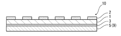
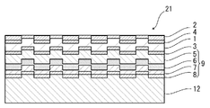
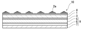
- the transfer sheet 10 has at least a transfer layer 9, a transfer base material 1, and a linear recessed shaping layer 2 in this order.
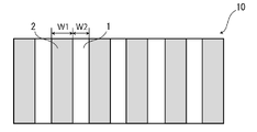
- a plurality of linear recessed shaping layers 2 are arranged on the transfer base material 1 at intervals.
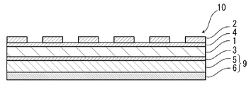
- a release layer 3 may be provided between the transfer base material 1 and the transfer layer 9 as necessary for the purpose of improving the releasability between the transfer base material 1 and the transfer layer 9. .
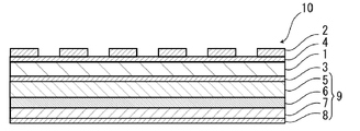
- a blocking prevention layer 4 may be provided between the transfer base material 1 and the linear recess shaping layer 2 in order to prevent blocking of the transfer sheet.
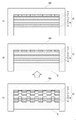
- the linear recess shaping layer 2 is a layer for forming a linear recess on the surface of the transfer layer 9 at the time of transfer of the transfer sheet 10. That is, the transfer sheet 10 is placed in the mold, the resin in a fluid state is injected into the mold 100 from the transfer layer 9 side, the resin is solidified, and the resin molded product (molded resin layer 12) is injected and molded at the same time.
- the linear recess shaping layer 2 provided on the transfer sheet 10 is embedded in the transfer substrate 1 and the linear recess shaping layer 9 is formed on the surface of the transfer layer 9.
- a linear recess 11 corresponding to the shape of the layer 2 is formed (see FIG. 10). Therefore, in the transfer sheet 10 according to the first aspect of the present disclosure, in order to form an uneven shape on the surface of the transfer layer 9, it is not necessary to provide the mold with an uneven shape corresponding to the uneven shape.
- the transfer layer 9 can include at least one of a protective layer 5, a primer layer 6, a decorative layer 7, and an adhesive layer 8.
- the transfer layer 9 preferably includes at least a protective layer 5. From the viewpoint of improving the adhesion of the protective layer 5, it is preferable to include the primer layer 6 on the side of the protective layer 5 opposite to the transfer substrate 1 side.
- the transfer sheet 10 according to the first aspect of the present disclosure may include a decorative layer 7 for the purpose of imparting decorativeness to the transfer sheet 10.
- the adhesive layer 8 may be provided on the surface of the transfer layer 9 on the side opposite to the transfer base material 1 side, if necessary. ..
- the transfer layer 9 is transferred to the molding resin layer 12 to become the resin molded product 20 according to the first aspect of the present disclosure.
- FIG. 1 shows a cross section of a transfer sheet in which a protective layer / transfer substrate / linear recess shaping layer is laminated in this order as one aspect of the transfer sheet laminated structure according to the first aspect of the present disclosure.
- a schematic diagram of the structure is shown.
- FIG. 3 as one aspect of the laminated structure of the transfer sheet according to the first aspect of the present disclosure, transfer in which a protective layer / a release layer / a transfer base material / a linear recess shaping layer is laminated in this order.
- the schematic diagram of the cross-sectional structure of one form of a sheet is shown. Further, in FIG.
- the protective layer / release layer / transfer substrate / blocking prevention layer / linear recess shaping layer are in this order.
- the schematic diagram of the cross-sectional structure of one form of the laminated transfer sheet is shown.
- a primer layer / a protective layer / a release layer / a transfer base material / a blocking prevention layer / a linear recessed shaping layer Shows a schematic diagram of a cross-sectional structure of one form of transfer sheets laminated in this order. Further, in FIG.
- a decorative layer / primer layer / protective layer / release layer / transfer substrate / blocking prevention layer / linear recess The schematic diagram of the cross-sectional structure of one form of the transfer sheet in which the shaping layer is laminated in this order is shown. Further, in FIG. 7, as one aspect of the laminated structure of the transfer sheet according to the first aspect of the present disclosure, an adhesive layer / decorative layer / primer layer / protective layer / release layer / transfer substrate / blocking prevention layer / The schematic diagram of the cross-sectional structure of one form of the transfer sheet in which the linear recess shaping layer is laminated in this order is shown. In addition, "/" means the delimiter between layers.
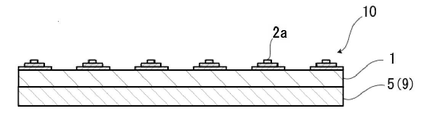
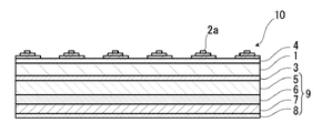
- the transfer sheet 10 has at least a transfer layer 9, a transfer base material 1, and a recessed shaping layer 2a in this order.
- the shape of the recessed shaping layer 2a is multi-stage. From the viewpoint of expressing various designs by the uneven shape formed on the transfer layer, it is preferable that a plurality of recessed shaping layers 2a are arranged on the transfer base material 1.
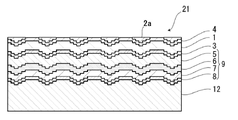
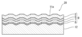
- a plurality of recessed shaping layers 2a provided on the transfer sheet 10 are embedded in the transfer base material 1, and a plurality of recesses corresponding to the recessed shaping layer 2a are formed on the surface of the transfer layer 9. This makes it possible to impart various designs utilizing the uneven shape to the surface of the resin molded product.
- each concave portion formed on the surface of the transfer layer 9 can be changed into a multi-stage shape (FIG. 20) by adjusting the number of stages and the height of the multi-stage concave shape shaping layer 2a. It can be conical, pyramidal (FIG. 21), etc., and various designs utilizing various concave shapes can be imparted to the surface of the resin molded product.
- a release layer 3 may be provided between the transfer base material 1 and the transfer layer 9 as necessary for the purpose of improving the releasability between the transfer base material 1 and the transfer layer 9. .. Further, a blocking prevention layer 4 may be provided between the transfer base material 1 and the recessed shaping layer 2a in order to prevent blocking of the transfer sheet.
- the transfer base material 1, the recessed shaping layer 2a, the mold release layer 3 provided as needed, and the blocking prevention layer 4 provided as needed are provided.
- the support constitutes a support, and the transfer sheet 10 is transferred, the transfer layer 9 is laminated on the molding resin layer 12, and then the support is peeled off.
- the recess shaping layer 2a is a layer for forming a recess on the surface of the transfer layer 9 at the time of transfer of the transfer sheet 10. That is, the transfer sheet 10 is placed in the mold, the resin in a fluid state is injected into the mold 100 from the transfer layer 9 side, the resin is solidified, and the resin molded product (molded resin layer 12) is injected and molded at the same time.
- the recessed shaping layer 2a provided on the transfer sheet 10 is embedded in the transfer base material 1, and the shape of the recessed shaping layer 2a is formed on the surface of the transfer layer 9.
- a recess 11 corresponding to the above is formed (see FIGS. 20 and 21). Therefore, in the transfer sheet 10 according to the second aspect of the present disclosure, in order to form an uneven shape on the surface of the transfer layer 9, it is not necessary to provide the mold with an uneven shape corresponding to the uneven shape.
- the transfer layer 9 can include at least one of a protective layer 5, a primer layer 6, a decorative layer 7, and an adhesive layer 8.
- the transfer layer 9 preferably includes at least a protective layer 5. From the viewpoint of improving the adhesion of the protective layer 5, it is preferable to include the primer layer 6 on the side of the protective layer 5 opposite to the transfer substrate 1 side.
- the transfer sheet 10 according to the second aspect of the present disclosure may include a decorative layer 7 for the purpose of imparting decorativeness to the transfer sheet 10.
- the adhesive layer 8 may be provided on the surface of the transfer layer 9 on the side opposite to the transfer base material 1 side, if necessary. ..
- the transfer layer 9 is transferred to the molding resin layer 12 to become the resin molded product 20 according to the second aspect of the present disclosure.
- the laminated structure of the transfer sheet according to the second aspect of the present disclosure the laminated structure in which the protective layer / transfer base material / recessed shaping layer are laminated in this order; the protective layer / release layer / transfer base material / recessed portion.
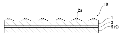
- FIG. 12 shows, as one aspect of the laminated structure of the transfer sheet according to the second aspect of the present disclosure, a cross-sectional structure of one form of the transfer sheet in which the protective layer / transfer base material / recessed shaping layer are laminated in this order.
- a schematic diagram is shown.
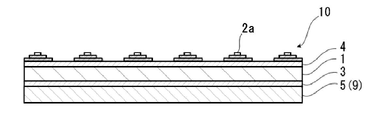
- FIG. 14 as one aspect of the laminated structure of the transfer sheet according to the second aspect of the present disclosure, the transfer sheet in which the protective layer / release layer / transfer base material / recessed shaping layer are laminated in this order.
- a schematic diagram of a cross-sectional structure of one form is shown. Further, in FIG.
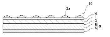
- a protective layer / a release layer / a transfer base material / a blocking prevention layer / a recessed shaping layer are laminated in this order.
- the schematic diagram of the cross-sectional structure of one form of the transfer sheet is shown.
- the primer layer / protective layer / release layer / transfer substrate / blocking prevention layer / recessed shaping layer is used as one aspect of the laminated structure of the transfer sheet according to the second aspect of the present disclosure.
- the schematic diagram of the cross-sectional structure of one form of transfer sheets laminated in order is shown. Further, in FIG.
- FIG. 19 as one aspect of the laminated structure of the transfer sheet according to the second aspect of the present disclosure, an adhesive layer / decorative layer / primer layer / protective layer / release layer / transfer substrate / blocking prevention layer / The schematic diagram of the cross-sectional structure of one form of the transfer sheet in which the concave shaping layer is laminated in this order is shown.
- "/" means the delimiter between layers.
- the transfer sheet according to the first aspect of the present disclosure has a transfer base material 1 and a linear recess shaping layer 2 as a support, and if necessary, a release layer 3 and a blocking prevention layer 4. Further have. At least one of the protective layer 5, the primer layer 6, the decorative layer 7, and the adhesive layer 8 formed on the transfer substrate 1 constitutes the transfer layer 9.
- the interface between the support and the transfer layer 9 is peeled off to obtain a resin molded product.
- the transfer sheet according to the second aspect of the present disclosure has a transfer base material 1 and a recessed shaping layer 2a as a support, and if necessary, a release layer 3 and a blocking prevention layer 4. Further have. At least one of the protective layer 5, the primer layer 6, the decorative layer 7, and the adhesive layer 8 formed on the transfer substrate 1 constitutes the transfer layer 9.
- the interface between the support and the transfer layer 9 is peeled off to obtain a resin molded product.
- Linear recess shaping layer 2 In the first aspect, a plurality of linear recessed shaping layers 2 are arranged on the transfer base material 1 (on the side opposite to the transfer layer 9 side) at intervals.
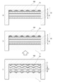
- the linear recess shaping layer 2 is a layer for forming a linear recess on the surface of the transfer layer 9 at the time of transfer of the transfer sheet 10. That is, the transfer sheet 10 is placed in the mold 100 (FIG. 10 (a)), and the resin in a fluid state is injected into the mold 100 from the transfer layer 9 side (FIG. 10 (b)) to solidify the resin.
- the transfer sheet 10 is integrated with the outer surface of the resin molded product (molded resin layer 12) at the same time as injection molding (FIG.
- each linear shape is formed from the viewpoint of preferably forming a linear recess 11 on the surface of the transfer layer 9 to be transferred to the molding resin layer 12 by the transfer of the transfer sheet 10.
- the line width W1 of the recessed shaping layer 2 is 200 ⁇ m or more, and the spacing W2 of each linear recessed shaping layer 2 is set to 0.7 times or more the line width W1 (see FIG. 2).
- the line width W1 of each linear recess shaping layer 2 is preferably about 200 m or more. More preferably, it is about 300 ⁇ m or more.
- the line width W1 is preferably about 400 ⁇ m or less, more preferably about 350 ⁇ m or less, and even more preferably about 300 ⁇ m or less.
- Preferred ranges of the line width W1 include about 200 to 400 ⁇ m, about 200 to 350 ⁇ m, about 200 to 300 ⁇ m, about 300 to 400 ⁇ m, about 300 to 350 ⁇ m, and the like.
- the spacing W2 of each linear recess shaping layer 2 is preferably the line width W1. Is about 0.7 times or more, more preferably about 1.0 times or more, still more preferably about 1.5 times or more.
- the interval W2 is about 0.7 to 4 times, about 0.7 to 3 times, about 0.7 to 2 times, about 1 to 4 times, about 1 to 3 times, and about 1 to 2 times the line width W1.
- the range of about 1.5 to 4 times, about 1.5 to 3 times, and about 1.5 to 2 times is preferable.
- each linear recess shaping layer 2 is preferably about 20 ⁇ m or more, more preferably. Is about 30 ⁇ m or more, preferably about 35 ⁇ m or more.
- the thickness of each linear recess shaping layer 2 is preferably about 50 ⁇ m or less, more preferably about 45 ⁇ m or less, and preferably about 40 ⁇ m or less.
- each linear concave portion shaping layer 2 is about 20 to 50 ⁇ m, about 20 to 45 ⁇ m, about 20 to 40 ⁇ m, about 30 to 50 ⁇ m, about 30 to 45 ⁇ m, about 30 to 40 ⁇ m, about 35 to 50 ⁇ m, and the like. Examples thereof include about 35 to 45 ⁇ m and about 35 to 40 ⁇ m.
- FIGS. 1 to 7 illustrate an embodiment in which the linear recess shaping layers 2 are arranged independently of each other, but each linear recess shaping layer 2 is at least. Some may be connected to each other.
- each linear concave portion shaping layer 2 is connected, there is an embodiment in which a plurality of convex portions constituting each linear concave portion shaping layer 2 are connected to each other to form one layer having an uneven shape.
- each linear concave portion shaping layer 2 is preferably about 5: 1 to 25: 1, and more preferably about 7.5: 1 to 15: 1.
- the length of each linear recess shaping layer 2 is preferably about 1 to 10 mm, more preferably about 2 to 5 mm.
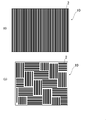
- each linear concave portion shaping layer 2 is not limited to the form extending linearly as shown in FIGS. 11 (a) and 11 (b), and can be appropriately set according to the target design.
- the shape of each linear concave portion shaping layer 2 is linear, parabolic, bicurve, sine wave curve, bicurve sine function curve, elliptical function curve, cycloid curve, etc. It may have a curved or wavy shape, or it may be a combination of a plurality of shapes.
- the line width W1 is 200 ⁇ m and the interval W2 satisfies 0.7 times or more of the line width W1.
- the limit is not particularly limited.
- FIG. 11 shows an example of the arrangement of the linear recess shaping layer 2 when the transfer sheet 10 according to the first aspect of the present disclosure is viewed in a plan view
- FIG. 11 (a) shows the linear recess.
- FIG. 11B is an example in which the shaping layers 2 are arranged side by side in the vertical direction
- FIG. 11B is an example in which the linear concave shape forming layers 2 are arranged side by side in the vertical direction and the horizontal direction in a pattern.
- the linear recess shaping layer 2 is formed of a cured product of a curable resin.
- the curable resin include thermosetting resins and ionizing radiation curable resins.
- thermosetting resin examples include unsaturated polyester resin, polyurethane resin (including two-component curable polyurethane), epoxy resin, aminoalkyd resin, phenol resin, urea resin, diallyl phthalate resin, and melamine.
- examples thereof include resins, guanamine resins, melamine-urea cocondensation resins, silicon resins, polysiloxane resins and the like.
- a curing agent such as a cross-linking agent and a polymerization initiator, and a polymerization accelerator can be added to the resin.
- a curing agent isocyanate, organic sulfonate and the like can be added to unsaturated polyester resin, polyurethane resin and the like, and organic amine and the like can be added to the epoxy resin.
- Peroxides such as methyl ethyl ketone peroxide and radical initiators such as azoisobutylnitrile can be added to the unsaturated polyester resin.
- the linear recess shaping layer 2 is preferably formed of a cured product of an ionizing radiation curable resin.
- the linear recess shaping layer 2 is coated with a curable resin by a roll coating method, a gravure coating method, a gravure printing method, a silk screen printing method, or a printing method using an inkjet printer, and dried. And can be formed by curing.
- a printing method using an inkjet printer is particularly preferable from the viewpoint of forming the interval W2 narrowly.
- the recessed shaping layer 2a is arranged on the transfer base material 1 (on the side opposite to the transfer layer 9 side).
- the recess shaping layer 2a is a layer for forming the recess 11a on the surface of the transfer layer 9 at the time of transfer of the transfer sheet 10. That is, the transfer sheet 10 is placed in the mold 100 (FIG. 22 (a)), and the resin in a fluid state is injected into the mold 100 from the transfer layer 9 side (FIG. 22 (b)) to solidify the resin. Then, at the same time as injection molding, the transfer sheet 10 is integrated with the outer surface of the resin molded product (molded resin layer 12) (FIG. 22 (c)).
- a plurality of recessed shaping layers 2a are arranged on the transfer base material 1.
- a plurality of recessed shaping layers 2a provided on the transfer sheet 10 are embedded in the transfer base material 1, and a plurality of recesses corresponding to the recessed shaping layer 2a are formed on the surface of the transfer layer 9.
- the shape of each concave portion formed on the surface of the transfer layer 9 can be changed into a multi-stage shape (FIG. 20) by adjusting the number of stages and the height of the multi-stage concave shape shaping layer 2a. It can be conical, pyramidal (FIG. 21), etc., and can be designed with various concave shapes on the surface of the resin molded product.
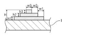
- FIG. 13 shows a schematic view when the transfer sheet of FIG. 12 is viewed in a plan view, the number of steps of the recessed shaping layer 2a is three, and the total height of the recessed shaping layer 2a.
- H the case where the height of the first step is h1, the height of the second step is h2, the height of the third step is h3, the width of the first step is w1, the width of the second step is w2, and the width of the third step is w3.
- the number of steps of the recess shaping layer 2a is not particularly limited, but when the shape of each recess shaped on the surface of the transfer layer 9 is multi-step, the width w of each step. Although it depends on the height h and the like, it is preferably about 2 to 5 steps, for example. Further, the shape of each concave portion formed on the surface of the transfer layer 9 is conical or pyramidal (the shape of each step of the concave portion shaping layer 2a is not reflected in the concave portion, and the concave portion 11a becomes a smooth slope. (See FIG. 21), although it depends on the width w of each step, for example, it is preferably 10 steps or more.
- the height H (overall height) of the concave portion shaping layer 2a is preferably about 20 ⁇ m from the viewpoint of preferably forming the concave portion 11a on the surface of the transfer layer 9 by the transfer of the transfer sheet 10. As mentioned above, it is more preferably about 30 ⁇ m or more, and preferably about 35 ⁇ m or more.
- the height H of the recessed forming layer 2a is preferably about 300 ⁇ m or less, more preferably about 250 ⁇ m or less, and preferably about 200 ⁇ m or less.
- the preferred range of the height H of the recessed forming layer 2a is about 20 to 300 ⁇ m, about 20 to 250 ⁇ m, about 20 to 200 ⁇ m, about 30 to 300 ⁇ m, about 30 to 250 ⁇ m, about 30 to 200 ⁇ m, about 35 to 300 ⁇ m, and the like. Examples thereof include about 35 to 250 ⁇ m and about 35 to 200 ⁇ m.
- the height h of each step of the recess shaping layer 2a is not particularly limited, but when the shape of each recess shaped on the surface of the transfer layer 9 is multi-step, each step is formed.
- the height h of the step is preferably about 10 ⁇ m or more, more preferably about 15 ⁇ m or more, and further preferably about 20 ⁇ m or more. Further, in this case, the height h of each step is preferably about 35 ⁇ m or less, more preferably about 30 ⁇ m or less, still more preferably about 25 ⁇ m or less.
- the preferred range of the height h of each step is about 10 to 35 ⁇ m, about 10 to 30 ⁇ m, about 10 to 25 ⁇ m, about 15 to 35 ⁇ m, about 15 to 30 ⁇ m, about 15 to 25 ⁇ m, about 20 to 35 ⁇ m, and so on. Examples thereof include about 20 to 30 ⁇ m and about 20 to 25 ⁇ m.
- the height h of each step is preferably about 30 ⁇ m or less, more preferably about 25 ⁇ m or less. More preferably, it is about 20 ⁇ m or less.
- the height h of each step is, for example, preferably about 10 ⁇ m or more.
- a preferable range of the height h of each step is about 10 to 30 ⁇ m, about 10 to 25 ⁇ m, and about 10 to 20 ⁇ m.
- the width w of each step of the recess shaping layer 2a is not particularly limited, but when the shape of each recess shaped on the surface of the transfer layer 9 is multi-step.
- the width w of each stage is preferably about 450 ⁇ m or more, more preferably about 800 ⁇ m or more, and further preferably about 900 ⁇ m or more. Further, in this case, the width w of each stage is preferably about 2000 ⁇ m or less, more preferably about 1500 ⁇ m or less, still more preferably about 1000 ⁇ m or less.
- the preferable range of the width w of each stage is about 450 to 2000 ⁇ m, about 450 to 1500 ⁇ m, about 450 to 1000 ⁇ m, about 800 to 2000 ⁇ m, about 800 to 1500 ⁇ m, about 800 to 1000 ⁇ m, about 900 to 2000 ⁇ m, 900. Examples thereof include about 1500 ⁇ m and about 900 to 1000 ⁇ m.
- the width w of each step is preferably about 100 ⁇ m or more, more preferably about 150 ⁇ m or more, and further. It is preferably about 200 ⁇ m or more.
- the width w of each stage is preferably about 450 ⁇ m or less, more preferably about 300 ⁇ m or less, still more preferably about 250 ⁇ m or less.
- the preferred range of the width w of each stage is about 100 to 450 ⁇ m, about 100 to 300 ⁇ m, about 100 to 250 ⁇ m, about 150 to 450 ⁇ m, about 150 to 300 ⁇ m, about 150 to 250 ⁇ m, about 200 to 450 ⁇ m, and 200. Examples thereof include about 300 ⁇ m and about 200 to 250 ⁇ m.
- the shape can be multi-stage, conical, pyramidal, or the like, and designs with various concave shapes can be imparted to the surface of the resin molded product. For example, if the height h of each step of the recess shaping layer 2a is small, it is difficult for the step to be formed in the recess to be formed, and the slope of the recess such as a cone or a pyramid tends to be smooth.
- FIGS. 12 to 19 exemplify an embodiment in which the recessed shaping layers 2a are arranged independently of each other, but each recessed shaping layer 2a is at least a part thereof. May be connected to each other in.
- each concave portion shaping layer 2a As an embodiment in which each concave portion shaping layer 2a is connected, a plurality of convex portions (multi-stage convex portions) constituting each concave shape shaping layer 2a are connected to each other to form one layer having a concave-convex shape. Aspects are mentioned.
- each recessed shaping layer 2a is arranged is not particularly limited. For example, by arranging a large number of each recessed shaping layer 2a in a matrix, a resin molded product 20 in which the recesses 11a are formed in a matrix on the surface can be obtained.
- the recessed shaping layer 2a is formed of a cured product of a curable resin.
- the curable resin include thermosetting resins and ionizing radiation curable resins.
- thermosetting resin examples include unsaturated polyester resin, polyurethane resin (including two-component curable polyurethane), epoxy resin, aminoalkyd resin, phenol resin, urea resin, diallyl phthalate resin, and melamine.
- examples thereof include resins, guanamine resins, melamine-urea cocondensation resins, silicon resins, polysiloxane resins and the like.
- a curing agent such as a cross-linking agent and a polymerization initiator, and a polymerization accelerator can be added to the resin.
- a curing agent isocyanate, organic sulfonate and the like can be added to unsaturated polyester resin, polyurethane resin and the like, and organic amine and the like can be added to the epoxy resin.
- Peroxides such as methyl ethyl ketone peroxide and radical initiators such as azoisobutylnitrile can be added to the unsaturated polyester resin.
- the recessed shaping layer 2a is preferably formed of a cured product of an ionizing radiation curable resin.
- the recessed shaping layer 2a is coated with a curable resin by a roll coating method, a gravure coating method, a gravure printing method, a silk screen printing method, or a printing method using an inkjet printer, and dried and cured. It can be formed by making it.
- a printing method using an inkjet printer is particularly preferable from the viewpoint of forming the recessed shaping layer 2a having a narrow width in each step.
- the transfer substrate 1 is used as a support that serves as a support member in the transfer sheet.
- the transfer substrate 1 used in the present disclosure is selected in consideration of vacuum forming suitability, and a resin sheet made of a thermoplastic resin is typically used.
- the thermoplastic resin include polyester resin; acrylic resin; polyolefin resin such as polypropylene and polyethylene; polycarbonate resin; acrylonitrile-butadiene-styrene resin (ABS resin); vinyl chloride resin and the like.
- the polyester sheet is used as the transfer base material 1. It is preferable to use.
- the polyester resin constituting the polyester sheet indicates a polymer containing an ester group obtained by polycondensation from a polyvalent carboxylic acid and a polyvalent alcohol, and is polyethylene terephthalate (PET), polybutylene terephthalate (PBT), or polyethylene naphthalate. (PEN) and the like can be preferably mentioned, and polyethylene terephthalate (PET) is particularly preferable in terms of heat resistance and dimensional stability.
- the polyester sheet suitably used as the transfer base material 1 in the present disclosure is manufactured as follows, for example.
- the above polyester resin and other raw materials are supplied to a well-known melt extruder such as an extruder, and heated to a temperature equal to or higher than the melting point of the polyester resin to melt.
- a rotary cooling drum so as to have a temperature equal to or lower than the glass transition temperature to obtain a substantially amorphous unoriented sheet.
- the stretching method may be sequential biaxial stretching or simultaneous biaxial stretching.
- the stretch ratio is preferably 7 times or less, more preferably 5 times or less, still more preferably 3 times or less.
- the transfer sheet does not shrink again in the temperature range when the molding resin is injected, and the required sheet strength can be obtained in the temperature range. can.
- the polyester sheet may be manufactured as described above, or a commercially available polyester sheet may be used.
- the transfer base material 1 has a physical structure such as an oxidation method or an unevenness method on one side or both sides, if desired, for the purpose of improving the adhesion to the release layer 3.
- Physical or chemical surface treatments can be applied. Examples of the oxidation method include corona discharge treatment, chromium oxidation treatment, flame treatment, hot air treatment, ozone / ultraviolet treatment method, and examples of the unevenness method include sandblasting method and solvent treatment method. These surface treatments are appropriately selected depending on the type of the transfer substrate 1, but in general, the corona discharge treatment method is preferably used from the viewpoints of effectiveness and operability.
- the transfer base material 1 may be subjected to a treatment such as forming an easy-adhesion layer for the purpose of enhancing the interlayer adhesion between the transfer base material 1 and the layer provided on the transfer base material 1.
- a treatment such as forming an easy-adhesion layer for the purpose of enhancing the interlayer adhesion between the transfer base material 1 and the layer provided on the transfer base material 1.
- the commercially available product may be one that has been subjected to the above-mentioned surface treatment in advance or one that is provided with an easy-adhesive layer.
- the thickness of the transfer substrate 1 is preferably usually 50 to 50. It is about 100 ⁇ m, more preferably about 60 to 75 ⁇ m.
- the transfer substrate 1 a single-layer sheet of these resins or a multi-layer sheet made of the same or different resins can be used.
- the transfer substrate 1 may or may not contain an additive.
- the additive include an ultraviolet absorber, an ultraviolet reflector, a colorant and the like.
- the release layer 3 is provided on the surface of the transfer base material 1 on the side where the transfer layer 9 is laminated, if necessary, for the purpose of enhancing the peelability between the transfer base material 1 and the transfer layer 9. Will be.
- the release layer 3 may be a solid release layer that covers the entire surface (the entire surface is solid), or may be provided in a part thereof. Usually, a solid release layer is preferable in consideration of peelability.
- the release layer 3 includes a silicone resin, a fluororesin, an acrylic resin (for example, an acrylic-melamine resin is included), a polyester resin, a polyolefin resin, a polystyrene resin, a polyurethane resin, and a cellulose resin. , Vinyl chloride-vinyl acetate copolymer resin, thermoplastic resin such as vitrified cotton, copolymer of the monomer forming the thermoplastic resin, ionizing radiation curable resin, or (meth) acrylic acid or these resins.
- the one modified with urethane can be formed by using a resin composition alone or a mixture of a plurality of them.
- acrylic resins polyester resins, polyolefin resins, polystyrene resins, copolymers of monomers forming these resins, and urethane-modified products thereof are preferable, and more specifically, acrylic-melamine.
- examples thereof include a resin composition mixed with the above emulsion.
- the ionizing radiation curable resin used for forming the release layer 3 is a resin that is crosslinked and cured by irradiation with ionizing radiation, and specifically, a polymerizable unsaturated bond or an epoxy group in the molecule. Examples thereof include those obtained by appropriately mixing at least one of a prepolymer, an oligomer, a monomer and the like having the above.
- the ionizing radiation is as described in the column of [Protective layer 5] described later.
- a (meth) acrylate monomer having a radically polymerizable unsaturated group in the molecule is preferable, and a polyfunctional (meth) acrylate monomer is particularly preferable.
- the polyfunctional (meth) acrylate monomer may be any (meth) acrylate monomer having two or more (bifunctional or higher), preferably three or more (trifunctional or higher) polymerizable unsaturated bonds in the molecule.
- polyfunctional (meth) acrylate monomer examples include ethylene glycol di (meth) acrylate, propylene glycol di (meth) acrylate, 1,4-butanediol di (meth) acrylate, and 1,6-hexanediol di ().
- Meta acrylate, neopentyl glycol di (meth) acrylate, polyethylene glycol di (meth) acrylate, hydroxypivalate neopentyl glycol di (meth) acrylate, dicyclopentanyldi (meth) acrylate, caprolactone-modified dicyclopentenyldi (meth) Meta) acrylate, ethylene oxide-modified di (meth) acrylate, allylated cyclohexyl di (meth) acrylate, isocyanurate di (meth) acrylate, trimethylol propanetri (meth) acrylate, ethylene oxide-modified trimethylol propanetri (meth) acrylate , Dipentaerythritol tri (meth) acrylate, propionic acid-modified dipentaerythritol tri (meth) acrylate, pentaerythritol tri (meth) acrylate, propylene oxide-modified trimethyl
- a (meth) acrylate oligomer having a radically polymerizable unsaturated group in the molecule is suitable, and among them, two or more polymerizable unsaturated bonds in the molecule.
- a polyfunctional (meth) acrylate oligomer having (bifunctional or higher) is preferable.
- the polyfunctional (meth) acrylate oligomer include polycarbonate (meth) acrylate, acrylic silicone (meth) acrylate, urethane (meth) acrylate, epoxy (meth) acrylate, polyester (meth) acrylate, and polyether (meth) acrylate.
- Examples thereof include polybutadiene (meth) acrylates, silicone (meth) acrylates, oligomers having a cationically polymerizable functional group in the molecule (for example, novolak type epoxy resin, bisphenol type epoxy resin, aliphatic vinyl ether, aromatic vinyl ether and the like).
- the polycarbonate (meth) acrylate is not particularly limited as long as it has a carbonate bond in the polymer main chain and has a (meth) acrylate group in the terminal or side chain, and for example, a polycarbonate polyol (meth) is used. It can be obtained by esterification with acrylic acid.
- the polycarbonate (meth) acrylate may be, for example, urethane (meth) acrylate having a polycarbonate skeleton.
- Urethane (meth) acrylate having a polycarbonate skeleton can be obtained, for example, by reacting a polycarbonate polyol with a polyhydric isocyanate compound and a hydroxy (meth) acrylate.
- Acrylic silicone (meth) acrylate can be obtained by radically copolymerizing a silicone macromonomer with a (meth) acrylate monomer.
- the urethane (meth) acrylate can be obtained, for example, by esterifying a polyurethane oligomer obtained by reacting a polyether polyol, a polyester polyol, or a caprolactone-based polyol with a polyisocyanate compound with (meth) acrylic acid.
- Epoxy (meth) acrylate can be obtained, for example, by reacting (meth) acrylic acid with an oxylan ring of a relatively low molecular weight bisphenol type epoxy resin or a novolak type epoxy resin to esterify it.
- a carboxyl-modified epoxy (meth) acrylate obtained by partially modifying this epoxy (meth) acrylate with a dibasic carboxylic acid anhydride can also be used.
- the polyester (meth) acrylate can be obtained, for example, by esterifying the hydroxyl group of a polyester oligomer having hydroxyl groups at both ends obtained by condensation of a polyvalent carboxylic acid and a polyhydric alcohol with (meth) acrylic acid, or to a polyvalent carboxylic acid. It can be obtained by esterifying the hydroxyl group at the end of the oligomer obtained by adding an alkylene oxide with (meth) acrylic acid.
- the polyether (meth) acrylate can be obtained by esterifying the hydroxyl group of the polyether polyol with (meth) acrylic acid.
- Polybutadiene (meth) acrylate can be obtained by adding (meth) acrylic acid to the side chain of the polybutadiene oligomer.
- the silicone (meth) acrylate can be obtained by adding (meth) acrylic acid to the terminal or side chain of a silicone having a polysiloxane bond in the main chain.
- the polyfunctional (meth) acrylate oligomer polycarbonate (meth) acrylate, urethane (meth) acrylate and the like are particularly preferable. These oligomers may be used alone or in combination of two or more.
- an ionizing radiation curable resin composition containing fine particles and the ionizing radiation curable resin is prepared and coated. It is performed by cross-linking and curing.
- the viscosity of the ionizing radiation curable resin composition may be any viscosity that can form an uncured resin layer by the coating method described later.
- the prepared coating liquid is applied by a known method such as gravure coat, bar coat, roll coat, reverse roll coat, comma coat, preferably gravure coat so as to have the above-mentioned thickness, and is uncured. Form a resin layer.
- the uncured resin layer thus formed is irradiated with ionizing radiation such as an electron beam and ultraviolet rays to cure the uncured resin layer to form the release layer 3.
- ionizing radiation such as an electron beam and ultraviolet rays
- the acceleration voltage thereof can be appropriately selected depending on the resin to be used and the thickness of the layer, but usually an acceleration voltage of about 70 to 300 kV can be mentioned.
- the higher the acceleration voltage the higher the transmission capacity. Therefore, when a resin that is easily deteriorated by electron beam irradiation is used under the release layer 3, the electron beam transmission depth and mold release The acceleration voltage is selected so that the thicknesses of the layers 3 are substantially equal. As a result, it is possible to suppress the irradiation of the layer located below the release layer 3 with the extra electron beam, and it is possible to minimize the deterioration of each layer due to the excess electron beam.
- the irradiation dose is preferably an amount at which the crosslink density of the release layer 3 is saturated, and is usually selected in the range of 5 to 300 kGy (0.5 to 30 Mrad), preferably 10 to 50 kGy (1 to 5 Mrad).
- the electron beam source is not particularly limited, and various electron beam accelerators such as a cockloft Walton type, a van de Graaff type, a resonance transformer type, an insulated core transformer type, a linear type, a dynamitron type, and a high frequency type can be used. Can be used.
- various electron beam accelerators such as a cockloft Walton type, a van de Graaff type, a resonance transformer type, an insulated core transformer type, a linear type, a dynamitron type, and a high frequency type can be used. Can be used.
- ultraviolet rays When ultraviolet rays are used as ionizing radiation, light rays including ultraviolet rays having a wavelength of 190 to 380 nm may be emitted.
- the ultraviolet source is not particularly limited, and examples thereof include a high-pressure mercury lamp, a low-pressure mercury lamp, a metal halide lamp, a carbon arc lamp, and an ultraviolet light emitting diode (LED-UV).
- the thickness of the release layer 3 is usually about 0.01 to 5 ⁇ m, preferably about 0.05 to 3 ⁇ m.
- the blocking prevention layer 4 is placed between the transfer base material 1 and the linear recess shaping layer 2 in order to effectively suppress blocking in the manufacturing process of the transfer sheet and the resin molded product. It is a layer provided between the transfer base material 1 and the recessed shaping layer 2a.
- the blocking prevention layer 4 is preferably formed of a resin composition containing fine particles and a thermoplastic resin.
- the thermoplastic resin is not particularly limited, but specifically, for example, an acrylic resin such as methyl poly (meth) acrylate; a polyolefin resin such as polypropylene and polyethylene; a polycarbonate resin; polyvinyl chloride and vinyl chloride-acetic acid.
- Vinyl chloride resins such as vinyl copolymers; polyethylene terephthalate (PET); acrylonitrile-butadiene-styrene resin (ABS resin); acrylonitrile-styrene-acrylic acid ester resin; and the like.
- PET polyethylene terephthalate
- ABS resin acrylonitrile-butadiene-styrene resin
- One type of thermoplastic resin may be used alone, or two or more types may be used in combination.
- the fine particles are not particularly limited, and known anti-blocking agents can be used.
- Examples of the fine particles include particles such as inorganic particles and resin particles.
- the inorganic particles are not particularly limited as long as they are particles formed of an inorganic compound, and examples thereof include silica particles, calcium carbonate particles, barium sulfate particles, alumina particles, and glass balloon particles, and among these, silica is preferable. Particles are mentioned. One type of inorganic particles may be used alone, or two or more types may be used in combination.
- the resin particles are not particularly limited as long as they are particles formed of resin, and are, for example, urethane beads, nylon beads, acrylic beads, silicone beads, styrene beads, melamine beads, urethane acrylic beads, polyester beads, and polyethylene. Beads and the like can be mentioned. One type of resin particles may be used alone, or two or more types may be used in combination.
- the particle size of the fine particles is, for example, 0.5 ⁇ m or more, preferably about 0.5 to 20 ⁇ m, and more preferably about 1 to 10 ⁇ m.
- the particle size of the fine particles is determined by injecting the powder to be measured from the nozzle using compressed air using the Shimadzu laser diffraction type particle size distribution measuring device SALD-2100 and dispersing it in the air. It is a value measured by a jet-type dry measuring method.
- the content of the fine particles in the blocking prevention layer 4 is not particularly limited, but is preferably about 1 to 15% by mass, and more preferably about 3 to 10% by mass.
- the thickness of the blocking prevention layer 4 is not particularly limited, but may be, for example, 10 ⁇ m or less, preferably about 1 to 10 ⁇ m, and more preferably about 2 to 5 ⁇ m. In the present disclosure, the thickness of the blocking prevention layer 4 means the thickness in the portion where the convex portion due to the fine particles does not exist.
- the particle size of the fine particles is preferably larger than the thickness of the blocking prevention layer 4.
- the particle size of the fine particles is preferably 1.1 to 5 times, more preferably 1.3 to 3 times the thickness of the blocking prevention layer 4.
- Transfer layer 9 In the transfer sheet of the present disclosure, at least one of the protective layer 5, the primer layer 6, the decorative layer 7, the adhesive layer 8, the transparent resin layer, and the like formed on the support constitutes the transfer layer 9. There is.
- a resin molded product is obtained in which the interface between the support and the transfer layer 9 is peeled off after the transfer sheet and the molding resin are integrally molded, and the transfer layer 9 of the transfer sheet is transferred to the molding resin layer 12. .
- each of these layers will be described in detail.
- the protective layer 5 is a layer provided on the transfer layer 9 so as to be located on the surface of the resin molded product, if necessary, in order to improve the scratch resistance and chemical resistance of the resin molded product.
- the resin forming the protective layer 5 is not particularly limited, and examples thereof include a thermosetting resin, a thermoplastic resin, and an ionizing radiation curable resin. Among these, an ionizing radiation curable resin is preferable from the viewpoint of achieving both excellent scratch resistance and excellent three-dimensional moldability.
- thermosetting resin forming the protective layer 5 is not particularly limited, and for example, acrylic polyol; polyester polyol; urethane polyol such as polyester urethane polyol, acrylic-urethane polyol; polyethylene polyol, polypropylene polyol, polybutadiene polyol, polyisoprene.
- Polyolefin polyols such as polyols; Examples thereof include resins containing a polyol resin such as and a curing agent.
- One type of thermosetting resin may be used alone, or two or more types may be used in combination.
- the thermoplastic resin forming the protective layer 5 is not particularly limited, and is, for example, an acrylic resin such as polymethyl (meth) acrylate and polyethyl (meth) acrylate; a polyolefin resin such as polypropylene and polyethylene; a polycarbonate resin; and a vinyl chloride type. Resins; polyethylene terephthalate (PET); acrylonitrile-butadiene-styrene resin (ABS resin); acrylonitrile-styrene-acrylic acid ester resin; and the like.
- PET polyethylene terephthalate
- ABS resin acrylonitrile-butadiene-styrene resin
- One type of thermoplastic resin may be used alone, or two or more types may be used in combination.
- the ionizing radiation curable resin used for forming the protective layer 5 is a resin that is crosslinked and cured by irradiation with ionizing radiation, and specifically, a polymerizable unsaturated bond or an epoxy group is formed in the molecule. Examples thereof include those obtained by appropriately mixing at least one of the prepolymers, oligomers, monomers and the like.
- ionizing radiation means an electromagnetic wave or a charged particle beam having an energy quantum capable of polymerizing or cross-linking a molecule, and usually ultraviolet (UV) or electron beam (EB) is used, but in addition, X It also includes electromagnetic waves such as rays and ⁇ rays, and charged particle beams such as ⁇ rays and ion rays.
- the electron beam curable resin is suitable for forming the protective layer 5 because it can be made solvent-free, does not require a photopolymerization initiator, and stable curing characteristics can be obtained. used.
- the protective layer 5 in the state of the laminated body may be cured, or may be uncured or semi-cured. There may be.
- the protective layer 5 in the state of the laminated body is uncured or semi-cured, the protective layer 5 is cured after forming the laminated body.
- a (meth) acrylate monomer having a radically polymerizable unsaturated group in the molecule is preferable, and a polyfunctional (meth) acrylate monomer is particularly preferable.
- the polyfunctional (meth) acrylate monomer may be any (meth) acrylate monomer having two or more (bifunctional or higher), preferably three or more (trifunctional or higher) polymerizable unsaturated bonds in the molecule.
- polyfunctional (meth) acrylate examples include ethylene glycol di (meth) acrylate, propylene glycol di (meth) acrylate, 1,4-butanediol di (meth) acrylate, and 1,6-hexanediol di (meth) acrylate.
- a (meth) acrylate oligomer having a radically polymerizable unsaturated group in the molecule is suitable, and among them, two or more polymerizable unsaturated bonds in the molecule.
- a polyfunctional (meth) acrylate oligomer having (bifunctional or higher) is preferable.
- the polyfunctional (meth) acrylate oligomer include polycarbonate (meth) acrylate, acrylic silicone (meth) acrylate, urethane (meth) acrylate, epoxy (meth) acrylate, polyester (meth) acrylate, and polyether (meth) acrylate.
- Examples thereof include polybutadiene (meth) acrylates, silicone (meth) acrylates, oligomers having a cationically polymerizable functional group in the molecule (for example, novolak type epoxy resin, bisphenol type epoxy resin, aliphatic vinyl ether, aromatic vinyl ether and the like).
- the polycarbonate (meth) acrylate is not particularly limited as long as it has a carbonate bond in the polymer main chain and has a (meth) acrylate group in the terminal or side chain, and for example, a polycarbonate polyol (meth) is used. It can be obtained by esterification with acrylic acid.
- the polycarbonate (meth) acrylate may be, for example, a polycarbonate-based urethane (meth) acrylate which is a urethane (meth) acrylate having a polycarbonate skeleton.
- Urethane (meth) acrylate having a polycarbonate skeleton can be obtained, for example, by reacting a polycarbonate polyol with a polyhydric isocyanate compound and a hydroxy (meth) acrylate.
- Acrylic silicone (meth) acrylate can be obtained by radically copolymerizing a silicone macromonomer with a (meth) acrylate monomer.
- the urethane (meth) acrylate can be obtained, for example, by esterifying a polyurethane oligomer obtained by reacting a polyether polyol, a polyester polyol, or a caprolactone-based polyol with a polyisocyanate compound with (meth) acrylic acid.
- Epoxy (meth) acrylate can be obtained, for example, by reacting (meth) acrylic acid with an oxylan ring of a relatively low molecular weight bisphenol type epoxy resin or a novolak type epoxy resin to esterify it.
- a carboxyl-modified epoxy (meth) acrylate obtained by partially modifying this epoxy (meth) acrylate with a dibasic carboxylic acid anhydride can also be used.
- the polyester (meth) acrylate can be obtained, for example, by esterifying the hydroxyl group of a polyester oligomer having hydroxyl groups at both ends obtained by condensation of a polyvalent carboxylic acid and a polyhydric alcohol with (meth) acrylic acid, or to a polyvalent carboxylic acid. It can be obtained by esterifying the hydroxyl group at the end of the oligomer obtained by adding an alkylene oxide with (meth) acrylic acid.
- the polyether (meth) acrylate can be obtained by esterifying the hydroxyl group of the polyether polyol with (meth) acrylic acid.
- Polybutadiene (meth) acrylate can be obtained by adding (meth) acrylic acid to the side chain of the polybutadiene oligomer.
- the silicone (meth) acrylate can be obtained by adding (meth) acrylic acid to the terminal or side chain of a silicone having a polysiloxane bond in the main chain.
- the polyfunctional (meth) acrylate oligomer polycarbonate (meth) acrylate (polycarbonate-based urethane (meth) acrylate and the like), urethane (meth) acrylate and the like are particularly preferable. These oligomers may be used alone or in combination of two or more.
- polycarbonate (meth) acrylate polycarbonate-based urethane (meth) acrylate, etc.
- a polycarbonate (meth) acrylate polycarbonate-based urethane (meth) acrylate or the like
- a polyfunctional (meth) acrylate other than the polycarbonate (meth) acrylate it is preferable to use polycarbonate (meth) acrylate (polycarbonate-based urethane (meth) acrylate, etc.) from the viewpoint of achieving both excellent scratch resistance and excellent three-dimensional moldability.
- a polycarbonate (meth) acrylate polycarbonate-based urethane (meth) acrylate or the like
- Polycarbonate (meth) acrylate is obtained, for example, by converting some or all of the hydroxyl groups of the polycarbonate polyol into (meth) acrylate (acrylic acid ester or methacrylic acid ester).
- This esterification reaction can be carried out by a usual esterification reaction.
- 1) a method of condensing a polycarbonate polyol with an acrylic acid halide or a methacrylate halide in the presence of a base and 2) a method of condensing a polycarbonate polyol with an acrylic acid anhydride or a methacrylate anhydride in the presence of a catalyst.
- 3) a method of condensing a polycarbonate polyol and acrylic acid or methacrylic acid in the presence of an acid catalyst can be mentioned.
- the above-mentioned polycarbonate polyol is a polymer having a carbonate bond in the polymer main chain and having two or more, preferably 2 to 50, more preferably 3 to 50 hydroxyl groups in the terminal or side chain.
- a typical method for producing this polycarbonate polyol is a method by polycondensation reaction with a diol compound (A), a trihydric or higher polyhydric alcohol (B), and a compound (C) as a carbonyl component.
- the diol compound (A) used as a raw material is represented by the general formula HO-R 1 -OH.
- R 1 is a divalent hydrocarbon group having 2 to 20 carbon atoms, and may contain an ether bond in the group. For example, a linear or branched alkylene group, a cyclohexylene group, or a phenylene group.
- diol compound (A) examples include ethylene glycol, 1,2-propylene glycol, diethylene glycol, dipropylene glycol, triethylene glycol, polyethylene glycol, neopentaneglycol, 1,3-propanediol, and 1,4-butane.
- Glycol 1,5-pentanediol, 3-methyl-1,5 pentanediol, 1,6-hexanediol, 1,8-octanediol, 1,3-bis (2-hydroxyethoxy) benzene, 1,4- Examples thereof include bis (2-hydroxyethoxy) benzene, 1,4-cyclohexanediol, and 1,4-cyclohexanedimethanol. These diols may be used alone or in combination of two or more.
- Examples of the trihydric or higher polyhydric alcohol (B) include alcohols such as trimethylolpropane, trimethylolethane, pentaerythritol, ditrimethylolpropane, dipentaerythritol, glycerin, and sorbitol. Further, alcohols having a hydroxyl group obtained by adding 1 to 5 equivalents of ethylene oxide, propylene oxide, or other alkylene oxide to the hydroxyl group of these polyhydric alcohols may be used. The polyhydric alcohol may be used alone or in combination of two or more.
- the compound (C) to be a carbonyl component is a compound selected from a carbonic acid diester, phosgene, or an equivalent thereof.
- Specific examples thereof include carbonate diesters such as dimethyl carbonate, diethyl carbonate, diisopropyl carbonate, diphenyl carbonate, ethylene carbonate and propylene carbonate, phosgene, and halogenated formic acid esters such as methyl chloroformate, ethyl chloroformate and phenyl chloroformate. And so on. These may be used alone or in combination of two or more.
- the polycarbonate polyol is synthesized by polycondensation reaction of the above-mentioned diol compound (A), trihydric or higher polyhydric alcohol (B), and compound (C) as a carbonyl component under general conditions. ..
- the charged molar ratio of the diol compound (A) to the polyhydric alcohol (B) is preferably in the range of 50:50 to 99: 1, and the diol compound of the compound (C) serving as a carbonyl component
- the charged molar ratio of A) to the polyhydric alcohol (B) is preferably 0.2 to 2 equivalents with respect to the hydroxyl groups of the diol compound and the polyhydric alcohol.
- the equivalent number (eq. / Mol) of the hydroxyl groups present in the polycarbonate polyol after the polycondensation reaction at the above charging ratio is 3 or more, preferably 3 to 50, more preferably 3 to 3 on average in one molecule. 20. Within this range, a required amount of (meth) acrylate groups are formed by the esterification reaction described later, and appropriate flexibility is imparted to the polycarbonate (meth) acrylate resin.
- the terminal functional group of this polycarbonate polyol is usually an OH group, but a part thereof may be a carbonate group.
- this polycarbonate polyol can also be produced by a transesterification reaction between a polycarbonate diol and a polyhydric alcohol having a valence of 3 or more.
- the molecular weight of the polycarbonate (meth) acrylate used in the present disclosure is preferably 500 or more, and more preferably 1,000 or more, in terms of the weight average molecular weight measured by GPC analysis and converted into standard polystyrene. , 2,000 or more is more preferable.
- the upper limit of the weight average molecular weight of the polycarbonate (meth) acrylate is not particularly limited, but is preferably 100,000 or less, more preferably 50,000 or less, from the viewpoint of controlling the viscosity so as not to become too high. More preferably, it is 2,000 or more and 50,000 or less, and particularly preferably 5,000 to 20,000.
- the polycarbonate (meth) acrylate is preferably used together with a polyfunctional (meth) acrylate other than the polycarbonate (meth) acrylate.
- the mass ratio of the polycarbonate (meth) acrylate to the polyfunctional (meth) acrylate is smaller than 98: 2 (that is, the amount of the polycarbonate (meth) acrylate is 98% by mass or less with respect to the total amount of the two components).
- the above-mentioned durability and chemical resistance are further improved.
- the mass ratio of the polycarbonate (meth) acrylate to the polyfunctional (meth) acrylate is larger than 50:50 (that is, the amount of the polycarbonate (meth) acrylate is 50% by mass or more with respect to the total amount of the two components. )
- Three-dimensional formability is further improved.
- the mass ratio of the polycarbonate (meth) acrylate to the polyfunctional (meth) acrylate is 95: 5 to 60:40.
- the polyfunctional (meth) acrylate other than the polycarbonate (meth) acrylate used in combination with the polycarbonate (meth) acrylate in the present disclosure may be any bifunctional or higher functional (meth) acrylate, and is not particularly limited.
- the bifunctional means having two ethylenically unsaturated bonds ⁇ (meth) acryloyl group ⁇ in the molecule.
- the number of functional groups is preferably about 2 to 6.
- the polyfunctional (meth) acrylate used in combination with the polycarbonate (meth) acrylate may be either an oligomer or a monomer, but from the viewpoint of achieving both excellent scratch resistance and excellent three-dimensional moldability, polyfunctional (meth) acrylate ( Meta) Acrylate oligomers are preferred.
- Examples of the polyfunctional (meth) acrylate oligomer used in combination with the polycarbonate (meth) acrylate include urethane (meth) acrylate-based oligomers, epoxy (meth) acrylate-based oligomers, polyester (meth) acrylate-based oligomers, and polyether (meth) oligomers. ) Examples thereof include acrylate-based oligomers.
- the urethane (meth) acrylate-based oligomer can be obtained, for example, by esterifying a polyurethane oligomer obtained by a reaction between a polyether polyol or a polyester polyol and a polyisocyanate with (meth) acrylic acid.
- the epoxy (meth) acrylate-based oligomer can be obtained, for example, by reacting (meth) acrylic acid with the oxylan ring of a relatively low molecular weight bisphenol type epoxy resin or novolak type epoxy resin to esterify it. Further, a carboxyl-modified epoxy (meth) acrylate oligomer obtained by partially modifying this epoxy (meth) acrylate-based oligomer with a dibasic carboxylic acid anhydride can also be used.
- the polyester (meth) acrylate-based oligomer for example, the hydroxyl group of the polyester oligomer having hydroxyl groups at both ends obtained by condensation of a polyvalent carboxylic acid and a polyhydric alcohol is esterified with (meth) acrylic acid, or many. It can be obtained by esterifying the hydroxyl group at the terminal of the oligomer obtained by adding an alkylene oxide to a valent carboxylic acid with a (meth) acrylic acid.
- the polyether (meth) acrylate-based oligomer can be obtained by esterifying the hydroxyl group of the polyether polyol with (meth) acrylic acid.
- polyfunctional (meth) acrylate oligomers used in combination with polycarbonate (meth) acrylate a highly hydrophobic polybutadiene (meth) acrylate-based oligomer having a (meth) acrylate group in the side chain of the polybutadiene oligomer, a main chain.
- examples thereof include silicone (meth) acrylate-based oligomers having a polysiloxane bond, and aminoplast resin (meth) acrylate-based oligomers obtained by modifying an aminoplast resin having many reactive groups in a small molecule.
- polyfunctional (meth) acrylate monomer used in combination with the polycarbonate (meth) acrylate include ethylene glycol di (meth) acrylate, propylene glycol di (meth) acrylate, and 1,4-butanediol di.
- a monofunctional (meth) acrylate can be appropriately used together with the polyfunctional (meth) acrylate for the purpose of lowering the viscosity thereof, as long as the purpose of the present disclosure is not impaired.
- the monofunctional (meth) acrylate include methyl (meth) acrylate, ethyl (meth) acrylate, propyl (meth) acrylate, butyl (meth) acrylate, pentyl (meth) acrylate, hexyl (meth) acrylate, and cyclohexyl (meth) acrylate.
- the content of the polycarbonate (meth) acrylate in the ionizing radiation curable resin composition forming the protective layer 5 is not particularly limited, but from the viewpoint of achieving both excellent scratch resistance and excellent three-dimensional moldability, the content thereof is not particularly limited. It is preferably about 98 to 50% by mass, and more preferably about 90 to 65% by mass.
- the protective layer 5 is formed using an ionizing radiation curable resin
- the protective layer 5 is formed, for example, by preparing an ionizing radiation curable resin composition, applying the same, and cross-linking and curing.
- the viscosity of the ionizing radiation curable resin composition may be any viscosity that can form an uncured resin layer by the coating method described later.
- the prepared coating liquid is applied by a known method such as a gravure coat, a bar coat, a roll coat, a reverse roll coat, a comma coat, preferably a gravure coat, so as to have a desired thickness.
- a gravure coat a bar coat, a roll coat, a reverse roll coat, a comma coat, preferably a gravure coat, so as to have a desired thickness.
- a cured resin layer is formed.
- the uncured resin layer thus formed is irradiated with ionizing radiation such as an electron beam and ultraviolet rays to cure the uncured resin layer to form the protective layer 5.
- ionizing radiation such as an electron beam and ultraviolet rays
- the acceleration voltage thereof can be appropriately selected depending on the resin to be used and the thickness of the layer, but usually an acceleration voltage of about 70 to 300 kV can be mentioned.
- the higher the acceleration voltage the higher the transmission capacity. Therefore, when a resin that is easily deteriorated by electron beam irradiation is used under the protective layer 5, the electron beam transmission depth and the protective layer 5 are used.
- the acceleration voltage is selected so that the thicknesses of the are substantially equal. Further, when the release layer 3 formed on the transfer substrate layer and the protective layer 5 are cured by an electron beam, the transmission depth of the electron beam and the total thickness of the release layer 3 and the protective layer 5 are increased. Select the acceleration voltage so that it is substantially equal. As a result, it is possible to suppress the irradiation of the transfer base material layer located under the release layer 3 with the extra electron beam, and it is possible to minimize the deterioration of the transfer base material layer due to the excess electron beam. can.
- the irradiation dose is an amount at which the crosslink density of the protective layer 5 becomes a sufficient value, and is preferably 30 to 300 kGy (3 to 30 Mrad), more preferably 30 to 100 kGy (3 to 10 Mrad).
- the number of functional groups of the polyfunctional (meth) acrylate is 2, and an appropriate irradiation dose is required according to the number of functional groups.
- the electron beam source is not particularly limited, and various electron beam accelerators such as a cockloft Walton type, a van de Graaff type, a resonance transformer type, an insulated core transformer type, a linear type, a dynamitron type, and a high frequency type can be used. Can be used.
- various electron beam accelerators such as a cockloft Walton type, a van de Graaff type, a resonance transformer type, an insulated core transformer type, a linear type, a dynamitron type, and a high frequency type can be used. Can be used.
- ultraviolet rays When ultraviolet rays are used as ionizing radiation, light rays including ultraviolet rays having a wavelength of 190 to 380 nm may be emitted.
- the ultraviolet source is not particularly limited, and examples thereof include a high-pressure mercury lamp, a low-pressure mercury lamp, a metal halide lamp, a carbon arc lamp, and an ultraviolet light emitting diode (LED-UV).
- the thickness of the protective layer 5 is not particularly limited, but is preferably about 1 to 30 ⁇ m, more preferably about 2 to 20 ⁇ m, and further preferably about 3 to 15 ⁇ m. When the thickness in such a range is satisfied, the laminated body can effectively exhibit excellent scratch resistance and excellent three-dimensional formability. Further, when the protective layer 5 is formed of an ionizing radiation curable resin, the ionizing radiation curable resin composition can be uniformly irradiated with ionizing radiation, so that the protective layer 5 can be uniformly cured, which is economical. It is also advantageous.
- the primer layer 6 is a layer provided on the transfer layer 9 as needed for the purpose of improving the adhesion of the protective layer 5.
- the primer layer 6 is preferably provided adjacent to the protective layer 5.
- the primer layer 6 can be formed by a resin composition for forming a primer layer.
- the resin used in the resin composition for forming the primer layer is not particularly limited, and is, for example, a polyol and / or a cured product thereof, a urethane resin, an acrylic resin, a (meth) acrylic-urethane copolymer resin, a polyester resin, and a butyral resin. And so on.
- these resins preferred examples include polyols and / or cured products thereof, urethane resins, acrylic resins, and acrylic urethane resins. These resins may be used alone or in combination of two or more.
- the primer layer 6 is preferably formed of a resin composition containing a polyol and a urethane resin.
- the polyol may be a compound having two or more hydroxyl groups in the molecule, and specific examples thereof include polyester polyols, polyethylene glycols, polypropylene glycols, acrylic polyols, and polyether polyols, and acrylic polyols are preferable. Can be mentioned.
- the mass ratio (polyurethane: urethane resin) of these is preferably about 5: 5 to 9.5: 0.5, more preferably 7: 3. ⁇ 9: 1 is mentioned.
- Examples of the cured product of the polyol include urethane resin.
- urethane resin polyurethane having a polyol (polyhydric alcohol) as a main component and an isocyanate as a cross-linking agent (curing agent) can be used.
- isocyanate examples include polyvalent isocyanates having two or more isocyanate groups in the molecule; aromatic isocyanates such as 4,4-diphenylmethane diisocyanate; hexamethylene diisocyanate, isophorone diisocyanate, hydrogenated tolylene diisocyanate, and hydrogen.
- aromatic isocyanates such as 4,4-diphenylmethane diisocyanate
- hexamethylene diisocyanate isophorone diisocyanate
- hydrogenated tolylene diisocyanate examples
- examples thereof include aliphatic (or alicyclic group) isocyanates such as added diphenylmethane diisocyanate.
- isocyanate is used as a curing agent, the content of isocyanate in the resin composition for forming a primer layer is not particularly limited, but from the viewpoint of adhesion and printability when laminating the decorative layer 7 or the like described later, it is considered. 3 to 45 parts by mass is prefer
- a combination of an acrylic polyol or a polyester polyol as a polyol and a hexamethylene diisocyanate or a 4,4-diphenylmethane diisocyanate as a cross-linking agent is preferable; more preferably.
- the acrylic resin is not particularly limited, and is, for example, a homopolymer of a (meth) acrylic acid ester, a copolymer of two or more different (meth) acrylic acid ester monomers, or a (meth) acrylic acid ester and others. Examples thereof include a copolymer with the monomer of. More specifically, the (meth) acrylic resin includes methyl poly (meth) acrylate, ethyl poly (meth) acrylate, propyl poly (meth) acrylate, butyl poly (meth) acrylate, and (meth) acrylate.
- Methyl- (meth) butyl acrylate copolymer ethyl (meth) acrylate- (meth) butyl acrylate copolymer, ethylene- (meth) methyl acrylate copolymer, styrene-methyl acrylate- (meth) acrylate
- examples thereof include (meth) acrylic acid esters such as polymers.
- the acrylic urethane resin is not particularly limited, and examples thereof include acrylic-urethane block copolymers, and specific examples thereof include acrylic-polyester urethane block copolymers.
- the ratio of acrylic to urethane in the acrylic-urethane block copolymer is not particularly limited, but for example, the acrylic / urethane ratio (mass ratio) is 9/1 to 1/9, preferably 8/2 to 2 /. 8 is mentioned.
- the thickness of the primer layer 6 is not particularly limited, but is, for example, about 0.1 to 10 ⁇ m, preferably about 1 to 10 ⁇ m (that is, the coating amount is, for example, about 0.1 to 10 g / m 2 , preferably 1 to 10 g /. m 2 ) can be mentioned. By satisfying such a thickness of the primer layer 6, the adhesion of the protective layer 5 can be effectively enhanced.
- additives can be added to the composition forming the primer layer 6 according to the desired physical properties to be provided.
- this additive include weather resistance improvers such as ultraviolet absorbers and light stabilizers, wear resistance improvers, polymerization inhibitors, cross-linking agents, infrared absorbers, antistatic agents, adhesive improvers, and leveling agents. Examples thereof include a thixophilic imparting agent, a coupling agent, a plasticizer, an antifoaming agent, a filler, a solvent, a coloring agent, a matting agent and the like. These additives can be appropriately selected from commonly used additives, and examples of the matting agent include silica particles and aluminum hydroxide particles.
- the ultraviolet absorber or light stabilizer a reactive ultraviolet absorber or light stabilizer having a polymerizable group such as a (meth) acryloyl group in the molecule can also be used.
- the primer layer 6 is a gravure coat, a gravure reverse coat, a gravure offset coat, a spinner coat, a roll coat, a reverse roll coat, a kiss coat, a wheeler coat, a dip coat, and a solid coat with a silk screen, using a resin composition for forming a primer layer. It is formed by a usual coating method such as wire bar coat, flow coat, comma coat, flow coat, brush coat, spray coat, or transfer coating method.
- the transfer coating method is a method in which a coating film of a primer layer 6 or an adhesive layer is formed on a thin sheet (film base material layer), and then the surface of the target layer in the laminate is coated.
- the primer layer 6 When forming the primer layer 6 on the surface of the protective layer 5, it may be formed on the protective layer 5 after curing. Further, a layer made of a primer layer forming composition is laminated on a layer of an ionizing radiation curable resin composition forming a protective layer 5 to form a primer layer 6, and then a layer made of an ionizing radiation curable resin is formed.
- the protective layer 5 may be formed by irradiating with ionizing radiation and curing the layer made of the ionizing radiation curable resin.
- the decorative layer 7 is a layer provided as needed to impart decorativeness to the resin molded product.
- the decorative layer 7 is usually composed of a pattern layer and / or a concealing layer.
- the pattern layer is a layer provided for expressing a pattern such as a pattern or characters
- the concealing layer is usually a solid layer on the entire surface and is provided for concealing coloring or the like of a molding resin or the like. It is a layer.
- the concealing layer may be provided inside the pattern layer in order to enhance the pattern of the pattern layer, or the decorative layer 7 may be formed by the concealing layer alone.
- the pattern of the pattern layer is not particularly limited, and examples thereof include patterns consisting of wood grain, stone grain, cloth grain, sand grain, geometric pattern, characters, and the like.
- the decorative layer 7 is formed by using a printing ink containing a colorant, a binder resin, and a solvent or a dispersion medium.
- the colorant of the printing ink used for forming the decorative layer 7 is not particularly limited, and for example, metals such as aluminum, chromium, nickel, tin, titanium, iron oxide, copper, gold, silver, and brass, and alloys.
- a metallic pigment consisting of scaly foil powder of a metal compound; mica-like iron oxide, titanium dioxide-coated mica, titanium dioxide-coated bismuth oxychloride, bismuth oxychloride, titanium dioxide-coated talc, fish scale foil, colored titanium dioxide-coated mica, basic Pearl luster pigments made of foil powder such as lead carbonate; fluorescent pigments such as strontium aluminate, calcium aluminate, barium aluminate, zinc sulfide, calcium sulfide; white inorganic substances such as titanium dioxide, zinc flower, antimony trioxide, etc.
- Pigments Zinc flower, petal pattern, vermilion, ultramarine, cobalt blue, titanium yellow, yellow lead, carbon black and other inorganic pigments; isoindolinone yellow, Hansa yellow A, quinacridon red, permanent red 4R, phthalocyanine blue, induthren blue Examples thereof include organic pigments (including dyes) such as RS and aniline black. These colorants may be used alone or in combination of two or more.
- the binder resin for the printing ink used for forming the decorative layer 7 is not particularly limited, but for example, acrylic resin, styrene resin, polyester resin, urethane resin, chlorinated polyolefin resin, vinyl chloride-.
- examples thereof include vinyl acetate copolymer resin, polyvinyl butyral resin, alkyd resin, petroleum resin, ketone resin, epoxy resin, melamine resin, fluororesin, silicone resin, fibrous derivative, rubber resin and the like.
- These binder resins may be used alone or in combination of two or more.
- the solvent or dispersion medium of the printing ink used for forming the decorative layer 7 is not particularly limited, but is, for example, a petroleum-based organic solvent such as hexane, heptane, octane, toluene, xylene, ethylbenzene, cyclohexane, and methylcyclohexane; Ester-based organic solvents such as ethyl acetate, butyl acetate, -2-methoxyethyl acetate and -2-ethoxyethyl acetate; alcohols such as methyl alcohol, ethyl alcohol, normal propyl alcohol, isopropyl alcohol, isobutyl alcohol, ethylene glycol and propylene glycol.
- a petroleum-based organic solvent such as hexane, heptane, octane, toluene, xylene, ethylbenzene, cyclohexane,
- Ketone organic solvent such as acetone, methyl ethyl ketone, methyl isobutyl ketone, cyclohexanone
- Ether organic solvent such as diethyl ether, dioxane, tetrahydrofuran
- Chlorine organic solvent such as dichloromethane, carbon tetrachloride, trichloroethylene, tetrachloroethylene
- Examples include water.
- the printing ink used for forming the decorative layer 7 includes, if necessary, an antioxidant, a curing catalyst, an ultraviolet absorber, an antioxidant, a leveling agent, a thickener, an antifoaming agent, a lubricant and the like. It may be included.
- the decorative layer 7 can be formed on an adjacent layer such as on the protective layer 5 or the primer layer 6 by a known printing method such as gravure printing, flexographic printing, silk screen printing, and offset printing.
- a known printing method such as gravure printing, flexographic printing, silk screen printing, and offset printing.
- the thickness of the decorative layer 7 is not particularly limited, and examples thereof include 1 to 40 ⁇ m, preferably 3 to 30 ⁇ m.
- the decorative layer 7 may be a metal thin film layer.
- the metal forming the metal thin film layer include tin, indium, chromium, aluminum, nickel, copper, silver, gold, platinum, zinc, and alloys containing at least one of them.
- the method for forming the metal thin film layer is not particularly limited, and examples thereof include a vapor deposition method such as a vacuum vapor deposition method, a sputtering method, and an ion plating method using the above-mentioned metal.
- a primer layer using a known resin may be provided on the front surface or the back surface of the metal thin film layer.
- the adhesive layer 8 is a layer provided on the back surface (molding resin layer 12 side) of the decorative layer 7 or the like, if necessary, for the purpose of improving the adhesion between the transfer layer 9 and the molding resin layer 12.
- the resin forming the adhesive layer 8 is not particularly limited as long as it can improve the adhesion and adhesiveness between these layers, and for example, a thermoplastic resin or a thermosetting resin is used.
- the thermoplastic resin include acrylic resin, acrylic modified polyolefin resin, chlorinated polyolefin resin, vinyl chloride-vinyl acetate copolymer, thermoplastic urethane resin, thermoplastic polyester resin, polyamide resin, rubber resin and the like. ..
- One type of thermoplastic resin may be used alone, or two or more types may be used in combination.
- the thermosetting resin include urethane resin and epoxy resin. One type of thermosetting resin may be used alone, or two or more types may be used in combination.
- the adhesive layer 8 is not necessarily a necessary layer, it is assumed that the transfer sheet of the present disclosure is applied to a decoration method by sticking on a resin molded body prepared in advance, for example, a vacuum crimping method described later. Is preferably provided. When used in the vacuum crimping method, it is preferable to form the adhesive layer 8 by using a conventional resin that develops adhesiveness by pressurization or heating among the various resins described above.
- the thickness of the adhesive layer 8 is not particularly limited, and examples thereof include about 0.1 to 30 ⁇ m, preferably about 0.5 to 20 ⁇ m, and more preferably about 1 to 8 ⁇ m.
- the resin molded product according to the first aspect of the present disclosure is formed by integrating the transfer sheet and the molded resin layer according to the first aspect of the present disclosure. .. Specifically, by transferring the molding resin layer 12 to the side opposite to the support of the transfer sheet, at least the molding resin layer 12, the transfer layer 9, the transfer base material 1, and the linear recess shaping are formed. A resin molded product 21 with a transfer substrate, in which the layers 2 are laminated in this order, is obtained (see, for example, FIG. 8).
- a resin molded product according to the first aspect of the present disclosure in which at least the molding resin layer 12 and the transfer layer 9 are laminated can be obtained. (See, for example, FIG. 9).
- a recess (for example, a protective layer) formed in the transfer layer (for example, a protective layer) of the resin molded product with respect to the height ( ⁇ m) of the linear recess shaping layer of the transfer sheet 10 (
- the ratio (formation rate) (%) of the depth ( ⁇ m) of the linear recessed shape layer formed by being buried in the transfer layer side by transfer is preferably 75% or more, more preferably. It is 80% or more, more preferably 85% or more.
- the height ( ⁇ m) of the linear recess shaping layer of the transfer sheet 10 according to the first aspect is the same as the depth ( ⁇ m) of the recess formed in the transfer layer (for example, the protective layer) of the resin molded product. If so, the shaping rate is 100%.
- the resin molded product according to the first aspect of the present disclosure can be manufactured by a manufacturing method including the following steps.
- the transfer sheet is placed in the mold (FIG. 10 (a)), the fluid resin is injected into the mold from the transfer layer side (FIG. 10 (b)), the resin is solidified, and the resin is solidified at the same time as injection molding.
- a transfer step of integrating the transfer sheet with the outer surface of the resin molded product (FIG. 10 (c)).
- the linear recess shaping layer provided on the transfer sheet is embedded in the transfer base material layer, and the linear recess 11 corresponding to the shape of the linear recess shaping layer is formed on the surface of the transfer layer.
- the resin molded product according to the second aspect of the present disclosure is formed by integrating the transfer sheet and the molded resin layer according to the second aspect of the present disclosure. Specifically, by transferring the molding resin layer 12 to the side opposite to the support of the transfer sheet, at least the molding resin layer 12, the transfer layer 9, the transfer base material 1, and the recessed shaping layer 2a are transferred. A resin molded product 21 with a transfer substrate, in which the above and the other are laminated in this order, is obtained (see, for example, FIG. 19). Next, by peeling the support from the resin molded product 21 with a transfer substrate, the resin molded product of the present disclosure in which at least the molding resin layer 12 and the transfer layer 9 are laminated can be obtained (see, for example, FIG. 20). ).
- the ratio (formation rate) (%) of the depth ( ⁇ m) of the recess formed by burying the shape layer on the transfer layer side by transfer is preferably 70% or more, more preferably 75% or more. More preferably, it is 80% or more.
- the height ( ⁇ m) of the recessed shaping layer of the transfer sheet 10 according to the second aspect and the depth ( ⁇ m) of the recess formed in the transfer layer (for example, the protective layer) of the resin molded product are the same.
- the shaping rate is 100%.
- examples of the method for producing the resin molded product of the present disclosure include methods including the following steps (1) to (5).
- the temperature for heating the transfer sheet is in the range of not less than the glass transition temperature of the transfer substrate 1 and less than the melting temperature (or melting point). Is preferable. Usually, it is more preferable to carry out at a temperature near the glass transition temperature.
- the vicinity of the glass transition temperature refers to a range of about ⁇ 5 ° C. of the glass transition temperature, and is generally about 70 to 130 ° C. when a polyester film suitable for the transfer substrate 1 is used.
- the step of heating the transfer sheet and the step of preforming the transfer sheet are omitted, and in the step (3) described later, the transfer sheet is subjected to the heat and pressure of the injection resin. May be molded into the shape of a mold.
- the molding resin described later is melted and injected into the cavity to integrate the transfer sheet and the molding resin.
- the molding resin is a thermoplastic resin, it is made to flow by heating and melting, and if the molding resin is a thermosetting resin, the uncured liquid composition is injected at room temperature or appropriately heated in a flowing state. Then, cool and solidify.
- the transfer sheet is integrally attached to the formed resin molded body, and becomes a resin molded product with a transfer base material.
- the heating temperature of the molding resin depends on the type of the molding resin, but is generally about 180 to 320 ° C.
- the resin molded product with a transfer base material thus obtained is cooled in the step (4), taken out from the mold, and then the support is peeled off from the protective layer 5 in the step (5) to perform resin molding. Get the goods. Further, the step of peeling the support from the protective layer 5 may be performed at the same time as the step of taking out the decorative resin molded product from the mold. That is, the step (5) may be included in the step (4).
- the resin molded product can also be manufactured by the vacuum crimping method.
- the vacuum crimping method first, the transfer sheet and the resin molded body of the present disclosure are placed in a vacuum crimping machine consisting of a first vacuum chamber located on the upper side and a second vacuum chamber located on the lower side, and the transfer sheet is placed in the first vacuum chamber.
- the two vacuum chambers are set in a vacuum state so that the resin molded body is on the second vacuum chamber side and the side on which the molding resin layer 12 of the transfer sheet is laminated faces the resin molded body side. do.
- the resin molded body is installed on an elevating table that can be raised and lowered up and down, which is provided on the second vacuum chamber side.
- the molded body is pressed against the transfer sheet using an elevating table, and the surface of the resin molded body is stretched while stretching the transfer sheet by utilizing the pressure difference between the two vacuum chambers. Attach to.
- the resin molded product of the present disclosure can be obtained by opening the two vacuum chambers to atmospheric pressure, peeling off the support, and trimming the excess portion of the transfer sheet as necessary.
- the vacuum crimping method it is preferable to include a step of heating the transfer sheet in order to soften the transfer sheet and improve the moldability before the step of pressing the molded body against the transfer sheet.
- the vacuum crimping method including this step may be particularly called a vacuum heating crimping method.
- the heating temperature in the step may be appropriately selected depending on the type of resin constituting the transfer sheet, the thickness of the transfer sheet, and the like. For example, when a polyester resin film or an acrylic resin film is used as the transfer base material 1. For example, it can usually be about 60 to 200 ° C.
- the molded resin layer 12 may be formed by selecting a resin according to the intended use.
- the molding resin that forms the molding resin layer 12 may be a thermoplastic resin or a thermosetting resin.
- thermoplastic resin examples include polyolefin resins such as polyethylene and polypropylene, ABS resins, styrene resins, polycarbonate resins, acrylic resins, vinyl chloride resins and the like. These thermoplastic resins may be used alone or in combination of two or more.
- thermosetting resin examples include urethane resin and epoxy resin. These thermosetting resins may be used alone or in combination of two or more.
- the transfer base material serves as a protective sheet for the resin molded product, so that the resin molded product with a transfer base material should be stored as it is without being peeled off after production.
- the support may be peeled off at the time of use.
- the resin molded products of the present disclosure include, for example, interior materials or exterior materials of vehicles such as automobiles; fittings such as window frames and door frames; interior materials of buildings such as walls, floors and ceilings; television receivers, air conditioners and the like. It can be used as a housing for home appliances; as a container, etc.
- a polyethylene terephthalate film (thickness 75 ⁇ m) having an easy-adhesive layer formed on one surface was used.
- a blocking prevention layer (acrylic resin having a thickness of 1.5 ⁇ m containing 1% silica particles) was applied to the surface of the polyethylene terephthalate film opposite to the surface on which the easy-adhesive layer was formed.
- a release layer (thickness 1 ⁇ m) was formed by printing a coating liquid containing a melamine resin as a main component on the surface of the easy-adhesive layer of the polyethylene terephthalate film by gravure printing.
- the ionizing radiation curable resin composition is coated on the release layer with a bar coder so that the thickness after curing is 2 ⁇ m (that is, the thickness of the protective layer is 2 ⁇ m) to form a protective layer.
- a coating film for use was formed.
- the ionizing radiation curable resin composition is urethane acrylate.
- an electron beam having an acceleration voltage of 165 kV and an irradiation dose of 50 kGy (5Mrad) was irradiated from the coating film to cure the protective layer forming coating film to form a protective layer.
- a resin composition (acrylic polyol) for forming a primer layer was applied onto this protective layer by gravure printing to form a primer layer (thickness 1.5 ⁇ m).
- a black ink composition for forming a decorative layer containing a binder resin (acrylic resin 50% by mass, vinyl chloride-vinyl acetate copolymer resin 50% by mass) on the primer layer is used to decorate the entire surface with a single black color.
- a layer (thickness 5 ⁇ m) was formed by gravure printing.
- blocking is performed by forming an adhesive layer (thickness 1.5 ⁇ m) on the decorative layer by gravure printing using a resin composition for forming an adhesive layer containing an acrylic resin (softening temperature: 125 ° C.).
- a resin composition for forming an adhesive layer containing an acrylic resin softening temperature: 125 ° C.
- a laminate in which the prevention layer / transfer substrate / release layer / protective layer / primer layer / decorative layer / adhesive layer were laminated in this order was obtained.
- a linear concave portion shaping layer having a height, a line width, a line length, and an aspect ratio shown in Table 1 is provided at intervals shown in Table 1 using an inkjet printer. It was formed in the vertical direction and the horizontal direction (the number of patterns shown in Table 1 respectively).
- the resin composition used for forming the linear recess shaping layer was urethane acrylate to which a photopolymerization initiator was added, and was cured by an ultraviolet irradiation device attached to an inkjet
- the uneven shape was measured with a shape analysis laser microscope "VK-X1000" manufactured by KEYENCE, and the height of the linear recess shaping layer was determined. The line width and spacing were measured. Further, the surface of the protective layer from which the transfer base material of the resin molded product was peeled off was also measured in the same manner, and the depth of the recess formed in the protective layer was measured. The ratio of the depth ( ⁇ m) of the recess formed in the protective layer of the resin molded product to the height ( ⁇ m) of the linear recess shaping layer of the transfer sheet was calculated as the shaping rate (%). The results are shown in Table 1.
- a polyethylene terephthalate film (thickness 75 ⁇ m) having an easy-adhesive layer formed on one surface was used.
- a blocking prevention layer (acrylic resin having a thickness of 1.5 ⁇ m containing 1% silica particles) was applied to the surface of the polyethylene terephthalate film opposite to the surface on which the easy-adhesive layer was formed.
- a release layer (thickness 1 ⁇ m) was formed by printing a coating liquid containing a melamine resin as a main component on the surface of the easy-adhesive layer of the polyethylene terephthalate film by gravure printing.
- the ionizing radiation curable resin composition is coated on the release layer with a bar coder so that the thickness after curing is 2 ⁇ m (that is, the thickness of the protective layer is 2 ⁇ m) to form a protective layer.
- a coating film for use was formed.
- the ionizing radiation curable resin composition is urethane acrylate.
- an electron beam having an acceleration voltage of 165 kV and an irradiation dose of 50 kGy (5Mrad) was irradiated from the coating film to cure the protective layer forming coating film to form a protective layer.
- a resin composition (acrylic polyol) for forming a primer layer was applied onto this protective layer by gravure printing to form a primer layer (thickness 1.5 ⁇ m).
- a black ink composition for forming a decorative layer containing a binder resin (acrylic resin 50% by mass, vinyl chloride-vinyl acetate copolymer resin 50% by mass) on the primer layer is used to decorate the entire surface with a single black color.
- a layer (thickness 5 ⁇ m) was formed by gravure printing.
- blocking is performed by forming an adhesive layer (thickness 1.5 ⁇ m) on the decorative layer by gravure printing using a resin composition for forming an adhesive layer containing an acrylic resin (softening temperature: 125 ° C.).
- a laminate in which the prevention layer / transfer substrate / release layer / protective layer / primer layer / decorative layer / adhesive layer were laminated in this order was obtained.
- the recessed shaping layer shown in Table 1 the plan view shape is a regular hexagon, and the hexagonal columns are laminated in a multi-stage shape, the number of stages, the whole. The height of each step, the height of each step, and the width of each step (distance from the end of each step to the upper step (see FIG.
- the resin composition used for forming the recessed shaping layer was urethane acrylate to which a photopolymerization initiator was added, and was cured by an ultraviolet irradiation device attached to an inkjet printer.
- the uneven shape was measured with a shape analysis laser microscope "VK-X1000" manufactured by KEYENCE, and the total height H of the concave shaping layer was determined. The height h of the steps and the width w of each step were measured. Further, the surface of the protective layer from which the transfer base material of the resin molded product was peeled off was also measured in the same manner, and the depth of the recess formed in the protective layer was measured. The ratio of the depth ( ⁇ m) of the recess formed in the protective layer of the resin molded product to the total height H ( ⁇ m) of the recess shaping layer of the transfer sheet was calculated as the shaping rate (%). The results are shown in Table 2.
Landscapes
- Engineering & Computer Science (AREA)
- Manufacturing & Machinery (AREA)
- Mechanical Engineering (AREA)
- Decoration By Transfer Pictures (AREA)
- Injection Moulding Of Plastics Or The Like (AREA)
- Laminated Bodies (AREA)
Priority Applications (4)
| Application Number | Priority Date | Filing Date | Title |
|---|---|---|---|
| JP2022554066A JP7243933B2 (ja) | 2020-09-29 | 2021-09-29 | 転写シート及びこれを利用した樹脂成形品の製造方法 |
| CN202180066810.5A CN116323141A (zh) | 2020-09-29 | 2021-09-29 | 转印片和利用其的树脂成型品的制造方法 |
| EP21875738.3A EP4223480A4 (en) | 2020-09-29 | 2021-09-29 | TRANSFER SHEET AND METHOD FOR PRODUCING RESIN MOLDED ARTICLE USING SAME |
| JP2023034292A JP2023078211A (ja) | 2020-09-29 | 2023-03-07 | 転写シート及びこれを利用した樹脂成形品の製造方法 |
Applications Claiming Priority (4)
| Application Number | Priority Date | Filing Date | Title |
|---|---|---|---|
| JP2020-163838 | 2020-09-29 | ||
| JP2020163838 | 2020-09-29 | ||
| JP2020-163839 | 2020-09-29 | ||
| JP2020163839 | 2020-09-29 |
Publications (1)
| Publication Number | Publication Date |
|---|---|
| WO2022071441A1 true WO2022071441A1 (ja) | 2022-04-07 |
Family
ID=80951681
Family Applications (1)
| Application Number | Title | Priority Date | Filing Date |
|---|---|---|---|
| PCT/JP2021/035985 Ceased WO2022071441A1 (ja) | 2020-09-29 | 2021-09-29 | 転写シート及びこれを利用した樹脂成形品の製造方法 |
Country Status (4)
| Country | Link |
|---|---|
| EP (1) | EP4223480A4 (enExample) |
| JP (2) | JP7243933B2 (enExample) |
| CN (1) | CN116323141A (enExample) |
| WO (1) | WO2022071441A1 (enExample) |
Cited By (2)
| Publication number | Priority date | Publication date | Assignee | Title |
|---|---|---|---|---|
| JP7108151B1 (ja) * | 2021-10-01 | 2022-07-27 | 大日本印刷株式会社 | 加飾シート |
| WO2023053890A1 (ja) * | 2021-10-01 | 2023-04-06 | 大日本印刷株式会社 | 加飾シート |
Families Citing this family (1)
| Publication number | Priority date | Publication date | Assignee | Title |
|---|---|---|---|---|
| EP4603295A1 (en) * | 2024-02-15 | 2025-08-20 | Multi Griffe s.r.l. | Procedure for making transfers via an optimised printer |
Citations (7)
| Publication number | Priority date | Publication date | Assignee | Title |
|---|---|---|---|---|
| JPS641726A (en) | 1987-06-25 | 1989-01-06 | Dainippon Ink & Chem Inc | Production of polycarbonate polyol |
| JPH08252899A (ja) * | 1995-03-16 | 1996-10-01 | Dainippon Printing Co Ltd | 化粧材の製造方法 |
| JP2006239967A (ja) * | 2005-03-02 | 2006-09-14 | Nissha Printing Co Ltd | 転写シート |
| JP2015077713A (ja) * | 2013-10-16 | 2015-04-23 | 凸版印刷株式会社 | インモールド転写箔とその製造方法、および加飾成形品とその製造方法 |
| JP2015163434A (ja) | 2014-02-28 | 2015-09-10 | 大日本印刷株式会社 | 加飾シート |
| JP2016190333A (ja) * | 2015-03-30 | 2016-11-10 | 大日本印刷株式会社 | 転写シート及びこれを用いた加飾樹脂成形品 |
| JP2018144235A (ja) * | 2017-03-01 | 2018-09-20 | 大日本印刷株式会社 | 三次元成形用転写シート及び加飾樹脂成形品の製造方法 |
Family Cites Families (9)
| Publication number | Priority date | Publication date | Assignee | Title |
|---|---|---|---|---|
| JPH0825789A (ja) * | 1994-07-12 | 1996-01-30 | Dainippon Printing Co Ltd | 転写シート |
| DE102009031478A1 (de) * | 2009-07-01 | 2011-01-05 | Leonhard Kurz Stiftung & Co. Kg | Mehrschichtkörper |
| WO2013133375A1 (ja) * | 2012-03-08 | 2013-09-12 | 株式会社 きもと | 熱転写用シートおよび印画物の製造方法 |
| JP6260219B2 (ja) * | 2013-11-18 | 2018-01-17 | 凸版印刷株式会社 | インモールド成形用転写フィルム及びそれを用いた成形品 |
| WO2016159119A1 (ja) * | 2015-03-30 | 2016-10-06 | 大日本印刷株式会社 | 加飾シート |
| JP6561591B2 (ja) * | 2015-03-30 | 2019-08-21 | 大日本印刷株式会社 | 加飾シート |
| JP6728569B2 (ja) * | 2015-03-30 | 2020-07-22 | 大日本印刷株式会社 | 転写シート及びこれを用いた加飾樹脂成形品 |
| JP6972527B2 (ja) * | 2016-09-30 | 2021-11-24 | 大日本印刷株式会社 | 加飾シート、加飾樹脂成形品、及びこれらの製造方法 |
| JP6965919B2 (ja) * | 2017-03-31 | 2021-11-10 | 大日本印刷株式会社 | 加飾シート、加飾樹脂成形品、及びこれらの製造方法 |
-
2021
- 2021-09-29 EP EP21875738.3A patent/EP4223480A4/en active Pending
- 2021-09-29 CN CN202180066810.5A patent/CN116323141A/zh active Pending
- 2021-09-29 WO PCT/JP2021/035985 patent/WO2022071441A1/ja not_active Ceased
- 2021-09-29 JP JP2022554066A patent/JP7243933B2/ja active Active
-
2023
- 2023-03-07 JP JP2023034292A patent/JP2023078211A/ja not_active Withdrawn
Patent Citations (7)
| Publication number | Priority date | Publication date | Assignee | Title |
|---|---|---|---|---|
| JPS641726A (en) | 1987-06-25 | 1989-01-06 | Dainippon Ink & Chem Inc | Production of polycarbonate polyol |
| JPH08252899A (ja) * | 1995-03-16 | 1996-10-01 | Dainippon Printing Co Ltd | 化粧材の製造方法 |
| JP2006239967A (ja) * | 2005-03-02 | 2006-09-14 | Nissha Printing Co Ltd | 転写シート |
| JP2015077713A (ja) * | 2013-10-16 | 2015-04-23 | 凸版印刷株式会社 | インモールド転写箔とその製造方法、および加飾成形品とその製造方法 |
| JP2015163434A (ja) | 2014-02-28 | 2015-09-10 | 大日本印刷株式会社 | 加飾シート |
| JP2016190333A (ja) * | 2015-03-30 | 2016-11-10 | 大日本印刷株式会社 | 転写シート及びこれを用いた加飾樹脂成形品 |
| JP2018144235A (ja) * | 2017-03-01 | 2018-09-20 | 大日本印刷株式会社 | 三次元成形用転写シート及び加飾樹脂成形品の製造方法 |
Non-Patent Citations (1)
| Title |
|---|
| See also references of EP4223480A4 |
Cited By (3)
| Publication number | Priority date | Publication date | Assignee | Title |
|---|---|---|---|---|
| JP7108151B1 (ja) * | 2021-10-01 | 2022-07-27 | 大日本印刷株式会社 | 加飾シート |
| WO2023053890A1 (ja) * | 2021-10-01 | 2023-04-06 | 大日本印刷株式会社 | 加飾シート |
| US12466158B2 (en) | 2021-10-01 | 2025-11-11 | Dai Nippon Printing Co., Ltd. | Decorative sheet |
Also Published As
| Publication number | Publication date |
|---|---|
| JP2023078211A (ja) | 2023-06-06 |
| CN116323141A (zh) | 2023-06-23 |
| JP7243933B2 (ja) | 2023-03-22 |
| EP4223480A4 (en) | 2024-10-23 |
| EP4223480A1 (en) | 2023-08-09 |
| JPWO2022071441A1 (enExample) | 2022-04-07 |
Similar Documents
| Publication | Publication Date | Title |
|---|---|---|
| CN106132704B (zh) | 三维成型用转印膜 | |
| JP7210981B2 (ja) | 積層体及び加飾物品 | |
| KR20160063352A (ko) | 장식 시트, 장식 수지 성형품, 및 장식 수지 성형품의 제조 방법 | |
| JP2023078211A (ja) | 転写シート及びこれを利用した樹脂成形品の製造方法 | |
| JP2019089335A (ja) | 三次元成形用転写フィルム | |
| JP6936977B2 (ja) | 三次元成形用転写シート及び加飾樹脂成形品の製造方法 | |
| JP7155540B2 (ja) | 三次元成形用転写フィルム及び樹脂成形品の製造方法 | |
| JP6728569B2 (ja) | 転写シート及びこれを用いた加飾樹脂成形品 | |
| CN109789686B (zh) | 三维成型用转印膜、其制造方法和树脂成型品的制造方法 | |
| JP6906981B2 (ja) | 三次元成形用転写シート及び加飾樹脂成形品の製造方法 | |
| JP6988332B2 (ja) | 三次元成形フィルム及び樹脂成形品 | |
| JP7725978B2 (ja) | 加飾シート及び加飾樹脂成形品 | |
| JP6690366B2 (ja) | 加飾シート及び加飾樹脂成形品の製造方法 | |
| JP7119506B2 (ja) | 三次元成形用転写フィルム、樹脂成形品、及びこれらの製造方法 | |
| JP2022056330A (ja) | 転写シート及びこれを利用した樹脂成形品の製造方法 | |
| JP7043769B2 (ja) | 加飾シート及び加飾樹脂成形品 | |
| WO2021199360A1 (ja) | 加飾シート及び加飾樹脂成形品 | |
| JP6955644B1 (ja) | 転写シート及びこれを利用した樹脂成形品の製造方法 | |
| JP7115659B2 (ja) | 加飾シート及び加飾樹脂成形品 | |
| JP2024146209A (ja) | 転写シート及びこれを利用した樹脂成形品の製造方法 | |
| JP7192218B2 (ja) | 三次元成形用転写フィルム、その製造方法、及び樹脂成形品の製造方法 | |
| JP2022157462A (ja) | 加飾シート、加飾樹脂成形品、及び加飾樹脂成形品の製造方法 | |
| JP6675039B1 (ja) | 加飾シート及び加飾樹脂成形品 | |
| JP2020049771A (ja) | 加飾シート及び加飾樹脂成形品 | |
| JP7354533B2 (ja) | 加飾シート及び樹脂成形品の製造方法 |
Legal Events
| Date | Code | Title | Description |
|---|---|---|---|
| 121 | Ep: the epo has been informed by wipo that ep was designated in this application |
Ref document number: 21875738 Country of ref document: EP Kind code of ref document: A1 |
|
| ENP | Entry into the national phase |
Ref document number: 2022554066 Country of ref document: JP Kind code of ref document: A |
|
| NENP | Non-entry into the national phase |
Ref country code: DE |
|
| ENP | Entry into the national phase |
Ref document number: 2021875738 Country of ref document: EP Effective date: 20230502 |