WO2022071075A1 - 防水構造およびロボット - Google Patents
防水構造およびロボット Download PDFInfo
- Publication number
- WO2022071075A1 WO2022071075A1 PCT/JP2021/034924 JP2021034924W WO2022071075A1 WO 2022071075 A1 WO2022071075 A1 WO 2022071075A1 JP 2021034924 W JP2021034924 W JP 2021034924W WO 2022071075 A1 WO2022071075 A1 WO 2022071075A1
- Authority
- WO
- WIPO (PCT)
- Prior art keywords
- shaft
- extension shaft
- waterproof structure
- cover member
- extension
- Prior art date
- Legal status (The legal status is an assumption and is not a legal conclusion. Google has not performed a legal analysis and makes no representation as to the accuracy of the status listed.)
- Ceased
Links
Images


Classifications
-
- F—MECHANICAL ENGINEERING; LIGHTING; HEATING; WEAPONS; BLASTING
- F16—ENGINEERING ELEMENTS AND UNITS; GENERAL MEASURES FOR PRODUCING AND MAINTAINING EFFECTIVE FUNCTIONING OF MACHINES OR INSTALLATIONS; THERMAL INSULATION IN GENERAL
- F16H—GEARING
- F16H25/00—Gearings comprising primarily only cams, cam-followers and screw-and-nut mechanisms
- F16H25/18—Gearings comprising primarily only cams, cam-followers and screw-and-nut mechanisms for conveying or interconverting oscillating or reciprocating motions
- F16H25/20—Screw mechanisms
- F16H25/22—Screw mechanisms with balls, rollers, or similar members between the co-operating parts; Elements essential to the use of such members
- F16H25/2204—Screw mechanisms with balls, rollers, or similar members between the co-operating parts; Elements essential to the use of such members with balls
-
- B—PERFORMING OPERATIONS; TRANSPORTING
- B25—HAND TOOLS; PORTABLE POWER-DRIVEN TOOLS; MANIPULATORS
- B25J—MANIPULATORS; CHAMBERS PROVIDED WITH MANIPULATION DEVICES
- B25J19/00—Accessories fitted to manipulators, e.g. for monitoring, for viewing; Safety devices combined with or specially adapted for use in connection with manipulators
- B25J19/0025—Means for supplying energy to the end effector
- B25J19/0029—Means for supplying energy to the end effector arranged within the different robot elements
-
- B—PERFORMING OPERATIONS; TRANSPORTING
- B25—HAND TOOLS; PORTABLE POWER-DRIVEN TOOLS; MANIPULATORS
- B25J—MANIPULATORS; CHAMBERS PROVIDED WITH MANIPULATION DEVICES
- B25J19/00—Accessories fitted to manipulators, e.g. for monitoring, for viewing; Safety devices combined with or specially adapted for use in connection with manipulators
- B25J19/0075—Means for protecting the manipulator from its environment or vice versa
-
- B—PERFORMING OPERATIONS; TRANSPORTING
- B25—HAND TOOLS; PORTABLE POWER-DRIVEN TOOLS; MANIPULATORS
- B25J—MANIPULATORS; CHAMBERS PROVIDED WITH MANIPULATION DEVICES
- B25J9/00—Program-controlled manipulators
- B25J9/02—Program-controlled manipulators characterised by movement of the arms, e.g. cartesian coordinate type
- B25J9/04—Program-controlled manipulators characterised by movement of the arms, e.g. cartesian coordinate type by rotating at least one arm, excluding the head movement itself, e.g. cylindrical coordinate type or polar coordinate type
- B25J9/041—Cylindrical coordinate type
- B25J9/042—Cylindrical coordinate type comprising an articulated arm
- B25J9/044—Cylindrical coordinate type comprising an articulated arm with forearm providing vertical linear movement
-
- F—MECHANICAL ENGINEERING; LIGHTING; HEATING; WEAPONS; BLASTING
- F16—ENGINEERING ELEMENTS AND UNITS; GENERAL MEASURES FOR PRODUCING AND MAINTAINING EFFECTIVE FUNCTIONING OF MACHINES OR INSTALLATIONS; THERMAL INSULATION IN GENERAL
- F16H—GEARING
- F16H25/00—Gearings comprising primarily only cams, cam-followers and screw-and-nut mechanisms
- F16H25/18—Gearings comprising primarily only cams, cam-followers and screw-and-nut mechanisms for conveying or interconverting oscillating or reciprocating motions
- F16H25/20—Screw mechanisms
- F16H25/24—Elements essential to such mechanisms, e.g. screws, nuts
- F16H25/2418—Screw seals, wipers, scrapers or the like
-
- F—MECHANICAL ENGINEERING; LIGHTING; HEATING; WEAPONS; BLASTING
- F16—ENGINEERING ELEMENTS AND UNITS; GENERAL MEASURES FOR PRODUCING AND MAINTAINING EFFECTIVE FUNCTIONING OF MACHINES OR INSTALLATIONS; THERMAL INSULATION IN GENERAL
- F16H—GEARING
- F16H25/00—Gearings comprising primarily only cams, cam-followers and screw-and-nut mechanisms
- F16H25/18—Gearings comprising primarily only cams, cam-followers and screw-and-nut mechanisms for conveying or interconverting oscillating or reciprocating motions
- F16H25/20—Screw mechanisms
- F16H2025/2031—Actuator casings
Definitions
- the present invention relates to a waterproof structure and a robot.
- Patent Document 1 a bellows-shaped cover member that covers a ball screw spline (BS) shaft and can be expanded and contracted in the longitudinal direction of the BS shaft.
- BS ball screw spline
- Patent Documents 1 to 3 an extension shaft is connected to the upper end of the BS shaft, and the BS shaft and the extension shaft are covered with a cover member.
- the BS shaft and extension shaft rotate integrally around the longitudinal axis of the BS shaft.
- the upper end portion of the cover member is attached to the upper end portion of the extension shaft via a bearing so that the cover member is not twisted by the rotation of the BS shaft.
- a rotary seal is provided to seal between the upper end portion of the extension shaft and the upper end portion of the cover member for dustproof and waterproofing of the bearing.
- the rotary seal is an oil seal
- a special oil seal having a low sliding resistance is required to prevent the cover member from twisting, which increases the cost.
- the rotary seal is a labyrinth seal, it is inferior to the oil seal in waterproof performance.
- One aspect of the present disclosure is an extension shaft arranged coaxially with the ball screw spline shaft on the upper side of the ball screw spline shaft extending in the vertical direction, and a longitudinal axis of the extension shaft covering the extension shaft and the ball screw spline shaft.
- a tubular cover member that can be expanded and contracted in the direction along the Is a waterproof structure fixed to the upper end of the extension shaft.
- the robot 10 is a horizontal articulated robot including a base 11, a first arm 12, a second arm 13, and a ball screw spline (BS) shaft 14.
- BS ball screw spline
- the base 11 is fixed to the installation surface.
- One end of the first arm 12 is rotatably supported by the base 11 around the vertical first axis J1, and the first arm 12 is rotatable in the horizontal direction with respect to the base 11.
- One end of the second arm 13 is rotatably supported by the other end of the first arm 12 so as to be rotatable around the vertical second axis J2, and the second arm 13 can rotate horizontally with respect to the first arm 12. Is.
- the BS shaft 14 is supported on the other end of the second arm 13 so as to be linearly movable in the vertical direction along the third axis J3, which is the longitudinal axis of the BS shaft 14, and to be rotatable around the third axis J3.
- a tool (not shown) such as a hand is connected to the lower end of the BS shaft 14.
- the BS shaft 14 has a hollow circular tube shape that opens at least at the upper end, and a striatum such as wiring for a tool can be passed through the inside of the BS shaft 14.
- the robot 10 further includes a waterproof structure 1 for preventing water from entering the inside of the second arm 13 from the hole.
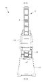
- the waterproof structure 1 includes an extension shaft (for example, the first shaft) 2 arranged coaxially with the BS shaft 14 on the upper side of the BS shaft (for example, the second shaft) 14, and the extension shaft 2.
- a rotary connecting portion 3 for connecting the BS shaft 14 to the BS shaft 14 and a tubular cover member 4 for covering the extension shaft 2 and the BS shaft 14 are provided.
- the extension shaft 2 connected to the upper end of the BS shaft 14 secures a distance for arranging the cover member 4 between the upper surface of the cover of the second arm 13 and the upper end of the extension shaft 2.
- the extension shaft 2 is a hollow circular tube that opens at both ends, and the inside of the extension shaft 2 communicates with the inside of the BS shaft 14.
- the rotary connecting portion 3 is arranged at the connecting portion between the BS shaft 14 and the extension shaft 2, and connects the BS shaft 14 and the extension shaft 2 so as to be relatively rotatable around the third axis J3.
- the rotary connecting portion 3 is a cylindrical bearing holder 5 arranged on the radial outer side of the lower end portion of the extension shaft 2 and fixed to the BS shaft 14, and the outer peripheral surface of the extension shaft 2 and the bearing holder 5. It is provided with a bearing 6 arranged between the inner peripheral surface and the inner peripheral surface.
- the bearing holder 5 is arranged radially outside the upper end portion of the BS shaft 14, a tubular first member 51 fixed to the upper end portion of the BS shaft 14, and radially outside the lower end portion of the extension shaft 2. It has a first member 51 and a fixed tubular second member 52.
- the first member 51 is a cylindrical member and has a slit that divides the first member 51 in the circumferential direction.
- the first member 51 is fixed to the outer peripheral surface of the upper end portion of the BS shaft 14 by tightening a bolt 7a that crosses the slit.
- the first member 51 and the second member 52 are mutually fixed by bolts 7b inserted in the first member 51 and the second member 52 in the longitudinal direction.
- the second member 52 has an inner diameter larger than the outer diameter of the extension shaft 2.
- the bearing 6 is arranged between the outer peripheral surface of the extension shaft 2 and the inner peripheral surface of the second member 52, the inner ring of the bearing 6 is fixed to the extension shaft 2, and the outer ring of the bearing 6 is fixed to the second member 52. ing.
- the extension shaft 2 and the bearing holder 5 are connected by a bearing 6 so as to be relatively rotatable.
- the cover member 4 has a bellows shape and can be expanded and contracted in the longitudinal direction.
- the cover member 4 extends vertically from the upper end portion of the extension shaft 2 to the upper surface of the cover of the second arm 13, and covers the extension shaft 2 and the protruding portion protruding upward from the second arm 13 of the BS shaft 14.
- the rotary connecting portion 3 is arranged in a cylindrical space S between the shafts 2 and 14 and the cover member 4.
- the cover member 4 may have a structure other than the bellows as long as it can expand and contract in the longitudinal direction while maintaining the closure of the space S.
- the lower end of the cover member 4 is fixed to the upper surface of the cover of the second arm 13, and a hole through which the BS shaft 14 passes is arranged inside the cover member 4.
- the cover member 4 that covers the hole prevents the liquid from entering the inside of the second arm 13 through the hole.
- the upper end portion of the cover member 4 is fixed to the upper end portion of the extension shaft 2.
- an annular plate-shaped flange portion 2a is provided at the upper end portion of the extension shaft 2
- an annular plate-shaped flange portion 4a is provided at the upper end portion of the cover member 4.
- the flange portion 2a is arranged on the flange portion 4a, and the flange portion 2a and the flange portion 4a are mutually fixed by bolts 7c.
- the waterproof structure 1 further includes a seal 81, a seal 82, and a labyrinth seal 9 in order to improve the airtightness of the space S and enhance the waterproof performance of the waterproof structure 1.
- the seal (first fixed seal) 81 seals between the upper end portion of the extension shaft 2 and the upper end portion of the cover member 4 to prevent liquid from entering the space S from the outside of the waterproof structure 1. Is.
- the seal 81 is arranged between the lower surface of the flange portion 2a and the upper surface of the flange portion 4a. Since the flange portion 2a and the flange portion 4a are fixed portions that are stationary with each other, a fixing seal such as a gasket is used as the seal 81.
- the seal (second fixed seal) 82 seals between the BS shaft 14 and the bearing holder 5 and prevents liquid from entering the space S from the inside of the shafts 2 and 14.
- the lower end surface of the second member 52 is provided with an annular convex portion 52c that fits inside the first member 51, and the lower end surface of the convex portion 52c and the upper end surface of the BS shaft 14 are aligned with each other. They are facing each other.
- the seal 82 is arranged between the lower end surface of the convex portion 52c and the upper end surface of the BS shaft 14. Since the BS shaft 14 and the bearing holder 5 are fixed portions that are stationary with each other, a fixed seal such as an O-ring is used as the seal 82.
- the labyrinth seal 9 is formed from the gaps 9a and 9b between the outer surface of the lower end portion of the extension shaft 2 and the inner surface of the bearing holder 5, and prevents liquid from entering the bearing 6 and the space S from the inside of the extension shaft 2. It is something to do.
- the inner surface of the second member 52 has an annular lower wall 52a facing the annular lower end surface of the extension shaft 2 and a cylindrical side wall 52b rising upward from the outer edge of the lower wall 52a. ..
- a horizontal annular gap 9a is provided between the lower end surface of the extension shaft 2 and the lower wall 52a, and a vertical cylindrical gap 9b is provided between the outer peripheral surface of the extension shaft 2 and the side wall 52b. ing.
- the bearing 6 is arranged above the labyrinth seal 9.
- the liquid that has entered the inside of the extension shaft 2 can enter the gap 9a in the horizontal direction, but is prevented from rising in the gap 9b by gravity. Therefore, the liquid is prevented from entering the bearing 6 on the upper side of the gap 9b.
- the BS shaft 14 and the extension shaft 2 are rotatably connected by the rotary connecting portion 3, only the BS shaft 14 rotates around the third axis J3, and the extension shaft 2 and the cover member 4 are connected to each other. They are stationary with each other without rotating around the 3-axis line J3. Therefore, an expensive part such as an oil seal is not required to seal between the upper end portion of the extension shaft 2 and the upper end portion of the cover member 4, and the extension shaft is provided with an inexpensive fixed seal 81 such as a gasket. It is possible to seal between the upper end portion of 2 and the upper end portion of the cover member 4. As a result, it is possible to realize high waterproof performance and cost reduction of the waterproof structure 1.
- the space between the BS shaft 14 and the bearing holder 5, which are fixed portions, is sealed by an inexpensive fixed seal 82 such as an O-ring.
- an inexpensive fixed seal 82 such as an O-ring.
- a labyrinth seal 9 is used for sealing between the lower end portion of the extension shaft 2 which is a rotating portion and the bearing holder 5.
- a contact-type rotary seal such as an oil seal
- the cover member is the cover member.
- Can join 4 the torsional force applied to the cover member 4 can be reduced and the life of the cover member 4 can be extended.
- the bearing 6 on the upper side of the labyrinth seal 9, it is possible to surely prevent the liquid from entering the bearing 6 and realize high waterproof performance of the rotating portion with an inexpensive configuration.
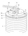
- the extension shaft 2 may have a fixing portion 2b for fixing the striatum 16 to the upper end portion of the extension shaft 2.
- the fixing portion 2b is a tap hole that opens in the upper end surface of the extension shaft 2, and the fixing member 15 is fixed to the upper end surface of the extension shaft 2 by fastening a bolt 7d in the tap hole 2b.
- the striatum 16 passes through the shafts 2 and 14 and is drawn out from the upper end surface of the extension shaft 2 and is fixed to the upper end portion of the extension shaft 2 by the fixing member 15. Since the extension shaft 2 does not rotate around the third axis J3, the striatum 16 can be fixed to the extension shaft 2 while preventing the striatum 16 from twisting.
- the waterproof structure 1 is provided with a seal 81 that seals between the upper end portion of the extension shaft 2 and the upper end portion of the cover member 4, but the upper end portion of the extension shaft 2 is provided by means other than the seal 81.
- the space between the portion and the upper end portion of the cover member 4 may be sealed. Since the upper end portion of the extension shaft 2 and the upper end portion of the cover member 4 are fixed portions, the sealing between the upper end portion of the extension shaft 2 and the upper end portion of the cover member 4 is performed by a seal other than a fixing seal such as a gasket. Various means can be used.
- the extension shaft 2 is a hollow tubular shape that opens at the upper end surface, but the extension shaft 2 may be a hollow shaft or a solid shaft that is closed at the upper end surface.
- the seal 82 and the labyrinth seal 9 may not be provided because the liquid does not enter the inside of the extension shaft 2.
- the robot 10 is a horizontal articulated robot, but the robot to which the waterproof structure 1 is applied is not limited to the horizontal articulated robot, and is any robot having a BS shaft extending in the vertical direction. May be.
- the waterproof structure 1 is provided with an extension shaft 2 connected to the BS shaft 14, but the waterproof structure of the present disclosure is optionally provided with two shafts coaxially arranged in series and rotating relative to each other. Can be applied to the structure of. That is, the waterproof structure covers the first shaft and the second shaft arranged along the longitudinal axis direction of the first shaft, and has a cover member that can be expanded and contracted in the longitudinal axis direction, and the first shaft and the second shaft are longitudinally arranged. It may be provided with a rotary connecting portion that is connected so as to be relatively rotatable around the axis.
- the waterproof structure preferably further comprises a seal that at least seals the fixed portion. For example, at least one of the space between the first shaft and the cover member and the space between the second shaft and the rotary connecting portion may be sealed by a seal.
Landscapes
- Engineering & Computer Science (AREA)
- Mechanical Engineering (AREA)
- General Engineering & Computer Science (AREA)
- Robotics (AREA)
- Manipulator (AREA)
- Sealing Using Fluids, Sealing Without Contact, And Removal Of Oil (AREA)
- Sealing Devices (AREA)
Abstract
Description
図1および図2に示されるように、ロボット10は、ベース11、第1アーム12、第2アーム13およびボールねじスプライン(BS)シャフト14を備える水平多関節ロボットである。
第1アーム12の一端部は、鉛直な第1軸線J1回りに回転可能にベース11に支持され、第1アーム12は、ベース11に対して水平方向に回転可能である。
第2アーム13の一端部は、鉛直な第2軸線J2回りに回転可能に第1アーム12の他端部に支持され、第2アーム13は、第1アーム12に対して水平方向に回転可能である。
例えば、第1部材51は、円筒状の部材であり、第1部材51を周方向に分断するスリットを有する。第1部材51は、スリットを横切るボルト7aを締め付けることによって、BSシャフト14の上端部の外周面に固定されている。第1部材51および第2部材52は、第1部材51および第2部材52に長手方向に挿入されたボルト7bによって相互に固定されている。
カバー部材4の上端部は延長シャフト2の上端部に固定されている。具体的には、延長シャフト2の上端部には円環板状のフランジ部2aが設けられ、カバー部材4の上端部には円環板状のフランジ部4aが設けられている。フランジ部2aはフランジ部4aの上に配置され、フランジ部2aおよびフランジ部4aがボルト7cによって相互に固定されている。
シール(第1の固定シール)81は、延長シャフト2の上端部とカバー部材4の上端部との間を封止し、防水構造1の外側から空間Sへ液体が侵入することを阻止するものである。
具体的には、シール81は、フランジ部2aの下面とフランジ部4aの上面との間に配置されている。フランジ部2aおよびフランジ部4aは相互に静止した固定部分であるので、シール81として、ガスケット等の固定シールが使用される。
具体的には、第2部材52の下端面には、第1部材51の内部に嵌合する円環状の凸部52cが設けられ、凸部52cの下端面とBSシャフト14の上端面とが相互に対向している。シール82は、凸部52cの下端面とBSシャフト14の上端面との間に配置されている。BSシャフト14およびベアリングホルダ5は相互に静止した固定部分であるので、シール82として、Oリング等の固定シールが使用される。
具体的には、第2部材52の内面は、延長シャフト2の円環状の下端面と対向する円環状の下壁52aと、下壁52aの外縁から上方に立ち上がる円筒状の側壁52bとを有する。延長シャフト2の下端面と下壁52aとの間に水平方向の円環状の隙間9aが設けられ、延長シャフト2の外周面と側壁52bとの間に鉛直方向の円筒状の隙間9bが設けられている。
ロボット10の作動時、第2アーム13内のモータ(図示略)からBSシャフト14に回転力が伝達されることによって、BSシャフト14は、第3軸線J3回りに回転しながら第3軸線J3に沿って上昇および下降する。BSシャフト14と共に延長シャフト2も上昇および下降する。カバー部材4は、延長シャフト2の上端部の上昇および下降によって伸縮変形する。このようなカバー部材4によって、外部から第2アーム13の内部へ液体が侵入することが阻止される。
また、ベアリング6をラビリンスシール9の上側に配置することによって、ベアリング6への液体の侵入を確実に防止し、回転部分の高い防水性能を安価な構成で実現することができる。
例えば、固定部2bは、延長シャフト2の上端面に開口するタップ穴であり、固定部材15が、タップ穴2b内にボルト7dを締結することによって延長シャフト2の上端面に固定される。線条体16は、シャフト2,14内を通って延長シャフト2の上端面から引き出され、固定部材15によって延長シャフト2の上端部に対して固定される。
延長シャフト2は第3軸線J3回りに回転しないので、線条体16のねじれを防止しながら線条体16を延長シャフト2に対して固定することができる。
2 延長シャフト
2b 固定部
3 回転連結部
4 カバー部材
5 ベアリングホルダ
6 ベアリング
81 第1の固定シール
82 第2の固定シール
9 ラビリンスシール
9a,9b 隙間
10 ロボット
14 ボールねじスプラインシャフト
15 固定部材
16 線条体
J1,J2,J3 軸線
Claims (8)
- 鉛直方向に延びるボールねじスプラインシャフトの上側に該ボールねじスプラインシャフトと同軸に配置される延長シャフトと、
該延長シャフトおよび前記ボールねじスプラインシャフトを覆い前記延長シャフトの長手軸に沿う方向に伸縮可能である筒状のカバー部材と、
前記ボールねじスプラインシャフトと前記延長シャフトとを前記長手軸回りに相対回転可能に連結する回転連結部とを備え、
前記カバー部材の上端部が前記延長シャフトの上端部と固定されている、防水構造。 - 前記延長シャフトの上端部と前記カバー部材の上端部との間を封止する第1の固定シールを備える請求項1に記載の防水構造。
- 前記回転連結部が、
前記延長シャフトの下端部の径方向外側に配置され前記ボールねじスプラインシャフトと固定される筒状のベアリングホルダと、
前記延長シャフトの外周面と前記ベアリングホルダの内周面との間に配置されたベアリングとを備える請求項1または請求項2に記載の防水構造。 - 前記延長シャフトの下端部の外面と前記ベアリングホルダの内面との間の隙間から形成されるラビリンスシールを備え、
前記ベアリングが、前記ラビリンスシールよりも上側に配置されている請求項3に記載の防水構造。 - 前記ボールねじスプラインシャフトと前記ベアリングホルダとの間を封止する第2の固定シールを備える請求項3または請求項4に記載の防水構造。
- 前記延長シャフトが、線条体を前記延長シャフトの上端部に固定するための固定部を有する請求項1から請求項5のいずれかに記載の防水構造。
- 請求項1から請求項6のいずれかに記載の防水構造を備えるロボット。
- 第1シャフトと前記第1シャフトの長手軸方向に沿って配置される第2シャフトとを覆い、前記長手軸方向に伸縮可能なカバー部材と、
前記第1シャフトと前記第2シャフトとを前記長手軸回りに相対回転可能に連結する回転連結部とを備え、
前記第1シャフトと前記カバー部材との間、および、前記第2シャフトと前記回転連結部との間の少なくとも一方が封止されている、防水構造。
Priority Applications (4)
| Application Number | Priority Date | Filing Date | Title |
|---|---|---|---|
| DE112021003840.0T DE112021003840T5 (de) | 2020-09-29 | 2021-09-24 | Wasserdichte struktur und roboter |
| CN202180064412.XA CN116234667A (zh) | 2020-09-29 | 2021-09-24 | 防水结构以及机器人 |
| US18/043,109 US12429120B2 (en) | 2020-09-29 | 2021-09-24 | Waterproof structure and robot |
| JP2022553873A JP7544839B2 (ja) | 2020-09-29 | 2021-09-24 | 防水構造およびロボット |
Applications Claiming Priority (2)
| Application Number | Priority Date | Filing Date | Title |
|---|---|---|---|
| JP2020-163445 | 2020-09-29 | ||
| JP2020163445 | 2020-09-29 |
Publications (1)
| Publication Number | Publication Date |
|---|---|
| WO2022071075A1 true WO2022071075A1 (ja) | 2022-04-07 |
Family
ID=80950481
Family Applications (1)
| Application Number | Title | Priority Date | Filing Date |
|---|---|---|---|
| PCT/JP2021/034924 Ceased WO2022071075A1 (ja) | 2020-09-29 | 2021-09-24 | 防水構造およびロボット |
Country Status (5)
| Country | Link |
|---|---|
| US (1) | US12429120B2 (ja) |
| JP (1) | JP7544839B2 (ja) |
| CN (1) | CN116234667A (ja) |
| DE (1) | DE112021003840T5 (ja) |
| WO (1) | WO2022071075A1 (ja) |
Citations (3)
| Publication number | Priority date | Publication date | Assignee | Title |
|---|---|---|---|---|
| JP2001039320A (ja) * | 1999-07-30 | 2001-02-13 | Koyo Seiko Co Ltd | ラックピニオン式ステアリング装置 |
| JP2012228733A (ja) * | 2011-04-25 | 2012-11-22 | Yamaha Motor Co Ltd | スカラ型ロボット |
| JP2020044560A (ja) * | 2018-09-20 | 2020-03-26 | 本田技研工業株式会社 | 抵抗溶接装置 |
Family Cites Families (5)
| Publication number | Priority date | Publication date | Assignee | Title |
|---|---|---|---|---|
| JP2009257458A (ja) * | 2008-04-16 | 2009-11-05 | Toshiba Mach Co Ltd | 送り装置及びロボット |
| JP5444858B2 (ja) | 2009-06-03 | 2014-03-19 | セイコーエプソン株式会社 | スカラロボット |
| JP5810608B2 (ja) * | 2011-04-28 | 2015-11-11 | セイコーエプソン株式会社 | アームカバー及びスカラ型ロボット |
| JP5845061B2 (ja) * | 2011-11-07 | 2016-01-20 | ヤマハ発動機株式会社 | クリーンロボット |
| JP7524662B2 (ja) * | 2020-08-04 | 2024-07-30 | セイコーエプソン株式会社 | ロボット |
-
2021
- 2021-09-24 DE DE112021003840.0T patent/DE112021003840T5/de active Pending
- 2021-09-24 WO PCT/JP2021/034924 patent/WO2022071075A1/ja not_active Ceased
- 2021-09-24 US US18/043,109 patent/US12429120B2/en active Active
- 2021-09-24 JP JP2022553873A patent/JP7544839B2/ja active Active
- 2021-09-24 CN CN202180064412.XA patent/CN116234667A/zh active Pending
Patent Citations (3)
| Publication number | Priority date | Publication date | Assignee | Title |
|---|---|---|---|---|
| JP2001039320A (ja) * | 1999-07-30 | 2001-02-13 | Koyo Seiko Co Ltd | ラックピニオン式ステアリング装置 |
| JP2012228733A (ja) * | 2011-04-25 | 2012-11-22 | Yamaha Motor Co Ltd | スカラ型ロボット |
| JP2020044560A (ja) * | 2018-09-20 | 2020-03-26 | 本田技研工業株式会社 | 抵抗溶接装置 |
Also Published As
| Publication number | Publication date |
|---|---|
| US12429120B2 (en) | 2025-09-30 |
| JPWO2022071075A1 (ja) | 2022-04-07 |
| DE112021003840T5 (de) | 2023-07-06 |
| JP7544839B2 (ja) | 2024-09-03 |
| CN116234667A (zh) | 2023-06-06 |
| US20230313868A1 (en) | 2023-10-05 |
Similar Documents
| Publication | Publication Date | Title |
|---|---|---|
| CN109154380B (zh) | 致动器 | |
| US7513173B2 (en) | Parallel link mechanism and industrial robot | |
| KR100814185B1 (ko) | 평행 링크 기구 및 산업용 로봇 | |
| JP5792988B2 (ja) | スカラ型ロボット | |
| JP6736679B2 (ja) | 減速機付きモータ及び多関節ロボット | |
| US20200370652A1 (en) | Seal member and robot | |
| US11913552B2 (en) | Sealing device and gear reducer | |
| CN1487225A (zh) | 轴向轴密封装置 | |
| JP2006289589A (ja) | 産業用ロボット | |
| CN114055443B (zh) | 机器人 | |
| WO2022071075A1 (ja) | 防水構造およびロボット | |
| JP2003181788A (ja) | ロボットの関節部構造 | |
| KR20190080745A (ko) | 산업용 로봇 | |
| JP2022029096A5 (ja) | ||
| JP7137041B1 (ja) | ロボット | |
| JP2009257458A (ja) | 送り装置及びロボット | |
| US20240123608A1 (en) | Linear motion mechanism and horizontal articulated robot | |
| JP7069855B2 (ja) | 車両用ドア開閉装置 | |
| CN211709349U (zh) | 一种二自由度水下机械手 | |
| JP2023157703A (ja) | ロボットアームとスカラロボット | |
| EP3872374A1 (en) | Sealing device and sealing structure | |
| CN201461961U (zh) | 波纹补偿避振密封装置 | |
| WO2026094148A1 (ja) | ロボット | |
| JP2012213259A (ja) | ダイレクトドライブモータ | |
| JP7218157B2 (ja) | 密封構造 |
Legal Events
| Date | Code | Title | Description |
|---|---|---|---|
| 121 | Ep: the epo has been informed by wipo that ep was designated in this application |
Ref document number: 21875377 Country of ref document: EP Kind code of ref document: A1 |
|
| ENP | Entry into the national phase |
Ref document number: 2022553873 Country of ref document: JP Kind code of ref document: A |
|
| 122 | Ep: pct application non-entry in european phase |
Ref document number: 21875377 Country of ref document: EP Kind code of ref document: A1 |
|
| WWG | Wipo information: grant in national office |
Ref document number: 18043109 Country of ref document: US |