WO2022070607A1 - 研磨装置、および研磨パッドの交換時期を決定する方法 - Google Patents
研磨装置、および研磨パッドの交換時期を決定する方法 Download PDFInfo
- Publication number
- WO2022070607A1 WO2022070607A1 PCT/JP2021/029120 JP2021029120W WO2022070607A1 WO 2022070607 A1 WO2022070607 A1 WO 2022070607A1 JP 2021029120 W JP2021029120 W JP 2021029120W WO 2022070607 A1 WO2022070607 A1 WO 2022070607A1
- Authority
- WO
- WIPO (PCT)
- Prior art keywords
- polishing
- index value
- polishing pad
- wear
- output values
- Prior art date
- Legal status (The legal status is an assumption and is not a legal conclusion. Google has not performed a legal analysis and makes no representation as to the accuracy of the status listed.)
- Ceased
Links
Images

Classifications
-
- B—PERFORMING OPERATIONS; TRANSPORTING
- B24—GRINDING; POLISHING
- B24B—MACHINES, DEVICES, OR PROCESSES FOR GRINDING OR POLISHING; DRESSING OR CONDITIONING OF ABRADING SURFACES; FEEDING OF GRINDING, POLISHING, OR LAPPING AGENTS
- B24B49/00—Measuring or gauging equipment for controlling the feed movement of the grinding tool or work; Arrangements of indicating or measuring equipment, e.g. for indicating the start of the grinding operation
- B24B49/18—Measuring or gauging equipment for controlling the feed movement of the grinding tool or work; Arrangements of indicating or measuring equipment, e.g. for indicating the start of the grinding operation taking regard of the presence of dressing tools
-
- B—PERFORMING OPERATIONS; TRANSPORTING
- B24—GRINDING; POLISHING
- B24B—MACHINES, DEVICES, OR PROCESSES FOR GRINDING OR POLISHING; DRESSING OR CONDITIONING OF ABRADING SURFACES; FEEDING OF GRINDING, POLISHING, OR LAPPING AGENTS
- B24B37/00—Lapping machines or devices; Accessories
- B24B37/005—Control means for lapping machines or devices
-
- B—PERFORMING OPERATIONS; TRANSPORTING
- B24—GRINDING; POLISHING
- B24B—MACHINES, DEVICES, OR PROCESSES FOR GRINDING OR POLISHING; DRESSING OR CONDITIONING OF ABRADING SURFACES; FEEDING OF GRINDING, POLISHING, OR LAPPING AGENTS
- B24B49/00—Measuring or gauging equipment for controlling the feed movement of the grinding tool or work; Arrangements of indicating or measuring equipment, e.g. for indicating the start of the grinding operation
- B24B49/003—Measuring or gauging equipment for controlling the feed movement of the grinding tool or work; Arrangements of indicating or measuring equipment, e.g. for indicating the start of the grinding operation involving acoustic means
-
- B—PERFORMING OPERATIONS; TRANSPORTING
- B24—GRINDING; POLISHING
- B24B—MACHINES, DEVICES, OR PROCESSES FOR GRINDING OR POLISHING; DRESSING OR CONDITIONING OF ABRADING SURFACES; FEEDING OF GRINDING, POLISHING, OR LAPPING AGENTS
- B24B49/00—Measuring or gauging equipment for controlling the feed movement of the grinding tool or work; Arrangements of indicating or measuring equipment, e.g. for indicating the start of the grinding operation
- B24B49/10—Measuring or gauging equipment for controlling the feed movement of the grinding tool or work; Arrangements of indicating or measuring equipment, e.g. for indicating the start of the grinding operation involving electrical means
-
- B—PERFORMING OPERATIONS; TRANSPORTING
- B24—GRINDING; POLISHING
- B24B—MACHINES, DEVICES, OR PROCESSES FOR GRINDING OR POLISHING; DRESSING OR CONDITIONING OF ABRADING SURFACES; FEEDING OF GRINDING, POLISHING, OR LAPPING AGENTS
- B24B49/00—Measuring or gauging equipment for controlling the feed movement of the grinding tool or work; Arrangements of indicating or measuring equipment, e.g. for indicating the start of the grinding operation
- B24B49/16—Measuring or gauging equipment for controlling the feed movement of the grinding tool or work; Arrangements of indicating or measuring equipment, e.g. for indicating the start of the grinding operation taking regard of the load
-
- B—PERFORMING OPERATIONS; TRANSPORTING
- B24—GRINDING; POLISHING
- B24B—MACHINES, DEVICES, OR PROCESSES FOR GRINDING OR POLISHING; DRESSING OR CONDITIONING OF ABRADING SURFACES; FEEDING OF GRINDING, POLISHING, OR LAPPING AGENTS
- B24B53/00—Devices or means for dressing or conditioning abrasive surfaces
- B24B53/017—Devices or means for dressing, cleaning or otherwise conditioning lapping tools
-
- H—ELECTRICITY
- H01—ELECTRIC ELEMENTS
- H01L—SEMICONDUCTOR DEVICES NOT COVERED BY CLASS H10
- H01L21/00—Processes or apparatus adapted for the manufacture or treatment of semiconductor or solid state devices or of parts thereof
- H01L21/02—Manufacture or treatment of semiconductor devices or of parts thereof
- H01L21/04—Manufacture or treatment of semiconductor devices or of parts thereof the devices having potential barriers, e.g. a PN junction, depletion layer or carrier concentration layer
- H01L21/18—Manufacture or treatment of semiconductor devices or of parts thereof the devices having potential barriers, e.g. a PN junction, depletion layer or carrier concentration layer the devices having semiconductor bodies comprising elements of Group IV of the Periodic Table or AIIIBV compounds with or without impurities, e.g. doping materials
- H01L21/30—Treatment of semiconductor bodies using processes or apparatus not provided for in groups H01L21/20 - H01L21/26
- H01L21/302—Treatment of semiconductor bodies using processes or apparatus not provided for in groups H01L21/20 - H01L21/26 to change their surface-physical characteristics or shape, e.g. etching, polishing, cutting
- H01L21/304—Mechanical treatment, e.g. grinding, polishing, cutting
-
- H—ELECTRICITY
- H01—ELECTRIC ELEMENTS
- H01L—SEMICONDUCTOR DEVICES NOT COVERED BY CLASS H10
- H01L21/00—Processes or apparatus adapted for the manufacture or treatment of semiconductor or solid state devices or of parts thereof
- H01L21/67—Apparatus specially adapted for handling semiconductor or electric solid state devices during manufacture or treatment thereof; Apparatus specially adapted for handling wafers during manufacture or treatment of semiconductor or electric solid state devices or components ; Apparatus not specifically provided for elsewhere
- H01L21/67005—Apparatus not specifically provided for elsewhere
- H01L21/67011—Apparatus for manufacture or treatment
- H01L21/67092—Apparatus for mechanical treatment
Definitions
- the present invention relates to a technique for determining a replacement time of a polishing pad used in a polishing device for polishing workpieces such as wafers, substrates, and panels.
- CMP Chemical mechanical polishing
- a workpiece for example, a wafer, a substrate, or a panel
- a polishing liquid containing abrasive grains such as silica (SiO 2 ) onto the polishing pad. It is a process of polishing the workpiece by sliding contact.
- the polishing apparatus for performing this CMP includes a polishing table that supports a polishing pad having a polishing surface, and a polishing head for pressing the workpiece against the polishing pad.
- the polishing device polishes the workpiece as follows.
- the polishing liquid (typically a slurry) is supplied to the polishing surface of the polishing pad while rotating the polishing table and the polishing pad integrally.
- the polishing head presses the surface of the workpiece against the polished surface of the polishing pad while rotating the workpiece.
- the workpiece is rubbed against the polishing pad in the presence of the polishing liquid.
- the surface of the workpiece is polished by the chemical action of the polishing liquid and the mechanical action of the abrasive grains and the polishing pad contained in the polishing liquid.
- dressing of the polishing pad with a dresser is performed.
- the dresser has hard abrasive grains such as diamond particles fixed on the lower surface thereof, and the polished surface of the polishing pad is scraped off by the dresser to regenerate the polished surface of the polishing pad.
- the dressing of the polishing pad is performed every time one workpiece is polished.
- the polishing pad gradually wears out as the dressing is repeated.
- the polishing pad is worn out, the intended polishing performance cannot be obtained, and it is necessary to replace the polishing pad regularly. Therefore, when the usage time of the polishing pad exceeds a predetermined time, or when the number of polished workpieces exceeds a predetermined number, the polishing pad is replaced with a new one. ..
- the usage time of the polishing pad and the number of polished workpieces only indirectly represent the wear of the polishing pad, and may not accurately reflect the wear of the polishing pad.
- polishing pads that have not reached the end of their service life may be replaced, or polishing pads that have been worn out beyond their usage limits may continue to be used.
- polishing pads that have been worn out beyond their usage limits may continue to be used.
- the work piece's target film thickness profile may not be achieved.
- the present invention provides an improved technique capable of accurately detecting wear or abnormality of the polishing pad and determining an appropriate processing time or replacement time of the polishing pad.
- a polishing table that supports the polishing pad, a polishing head that presses the workpiece against the polishing surface of the polishing pad, a dresser that dresses the polishing surface of the polishing pad, and friction between the dresser and the polishing pad.
- the wear index value is determined from the detection sensor fixed to the dresser and the plurality of output values of the detection sensor, and an alarm signal is output when the wear index value falls below a predetermined lower limit value.
- a polishing device is provided, which comprises a wear monitoring device configured to emit.
- the wear monitoring device is configured to perform frequency analysis on the plurality of output values arranged along the time axis to determine the wear index value.
- the frequency analysis is a Fourier transform
- the wear monitoring device is configured to apply the Fourier transform to the plurality of output values aligned along the time axis to create a power spectrum.
- the wear index value is the first peak value of the power spectrum.
- the wear monitoring device calculates a plurality of relative output values by subtracting the plurality of output values from the plurality of reference values, respectively, with respect to the plurality of relative output values arranged along the time axis. It is configured to perform frequency analysis to determine the wear index value.
- the frequency analysis is a Fourier transform and the wear monitoring device is configured to apply the Fourier transform to the plurality of relative output values aligned along the time axis to create a power spectrum.
- the wear index value is the first peak value of the power spectrum.
- the plurality of reference values are a plurality of output values of the detection sensor obtained when the dresser first dresses the polishing pad.
- the wear monitoring device is configured to detect an abnormality in the polishing pad when the second peak value of the power spectrum exceeds a predetermined upper limit value.
- the detection sensor is any one of an accelerometer, an acoustic emission sensor, and a strain sensor.
- the polishing apparatus further includes a polishing progress detector that generates a polishing index value indicating the progress of polishing of the workpiece, and an operation control unit that monitors the polishing index value, and the operation control unit. Is configured to correct the polishing index value based on the wear index value.
- it is a method of determining the replacement time of the polishing pad used in the polishing apparatus for the workpiece, in which the polishing surface of the polishing pad is dressed by a dresser and the friction between the dresser and the polishing pad is determined. Is detected by a detection sensor fixed to the dresser, a wear index value is determined from a plurality of output values of the detection sensor, and an alarm signal is issued when the wear index value falls below a predetermined lower limit value. Is provided.
- the step of determining the wear index value is a step of performing frequency analysis on the plurality of output values arranged along the time axis to determine the wear index value.
- the frequency analysis is a Fourier transform
- the step of determining the wear index value applies a Fourier transform to the plurality of output values arranged along the time axis to create a power spectrum. This is a step of determining the wear index value, which is the first peak value of the power spectrum.
- the step of determining the wear index value calculates a plurality of relative output values by subtracting the plurality of output values from the plurality of reference values, respectively, and the plurality of relative outputs arranged along the time axis.
- the frequency analysis is a Fourier transform
- the step of determining the wear index value applies a Fourier transform to the plurality of relative output values arranged along the time axis to create a power spectrum.
- This is a step of determining the wear index value, which is the first peak value of the power spectrum.
- the plurality of reference values are a plurality of output values of the detection sensor obtained when the dresser first dresses the polishing pad.
- the method further comprises the step of detecting anomalies in the polishing pad when the second peak value of the power spectrum exceeds a predetermined upper limit.
- the detection sensor is any one of an accelerometer, an acoustic emission sensor, and a strain sensor.
- the method further comprises a step of correcting a polishing index value indicating the progress of polishing of the workpiece based on the wear index value.
- the friction between the dresser and the polishing pad is detected by the detection sensor fixed to the dresser.
- the output value of the detection sensor gradually changes as the polishing pad wears.
- the output value of the detection sensor reflects the wear of the polishing pad. Therefore, the wear monitoring device can accurately determine the wear of the polishing pad and the replacement time of the polishing pad based on the wear index value obtained from the plurality of output values of the detection sensor.
- FIG. 4 is a diagram showing a power spectrum obtained by applying a Fourier transform (or a fast Fourier transform) to relative output values arranged along the time axis shown in FIG. 4.
- FIG. 6 is a diagram showing a power spectrum obtained by applying a Fourier transform (or a fast Fourier transform) to a plurality of output values of detection sensors arranged along the time axis shown in FIG.
- FIG. 1 is a schematic view showing an embodiment of a polishing device.
- the polishing device 1 is a device that chemically and mechanically polishes a workpiece W such as a wafer, a substrate, and a panel.
- the polishing apparatus 1 includes a polishing table 5 that supports a polishing pad 2 having a polishing surface 2a, a polishing head 7 that presses a workpiece W against the polishing surface 2a, and a polishing liquid (for example, polishing liquid (for example,).
- the polishing head 7 is configured to hold the workpiece W on its lower surface.
- the workpiece W has a film to be polished.
- the operation control unit 10 is composed of at least one computer.
- the operation control unit 10 includes a storage device 10a in which the program is stored, and an arithmetic unit 10b that executes an operation according to an instruction included in the program.
- the storage device 10a includes a main storage device such as a random access memory (RAM) and an auxiliary storage device such as a hard disk drive (HDD) and a solid state drive (SSD).
- Examples of the arithmetic unit 10b include a CPU (central processing unit) and a GPU (graphic processing unit).
- the specific configuration of the motion control unit 10 is not limited to these examples.
- the polishing device 1 further includes a support shaft 14, a polishing head swing arm 16 connected to the upper end of the support shaft 14, and a polishing head shaft 18 rotatably supported at the free end of the polishing head swing arm 16. ing.
- the polishing head 7 is fixed to the lower end of the polishing head shaft 18.
- a polishing head rotation mechanism (not shown) equipped with an electric motor or the like is arranged in the polishing head swing arm 16. This polishing head rotation mechanism is connected to the polishing head shaft 18, and is configured to rotate the polishing head shaft 18 and the polishing head 7 in the direction indicated by the arrow.
- the polishing head shaft 18 is connected to a polishing head elevating mechanism (including a ball screw mechanism) (not shown).
- This polishing head elevating mechanism is configured to move the polishing head shaft 18 up and down relative to the polishing head swing arm 16. Due to the vertical movement of the polishing head shaft 18, the polishing head 7 can move up and down relatively with respect to the polishing head swing arm 16 and the polishing table 5, as shown by arrows.
- the polishing device 1 further includes a table rotation motor 21 that rotates the polishing pad 2 and the polishing table 5 around their axes.
- the table rotation motor 21 is arranged below the polishing table 5, and the polishing table 5 is connected to the table rotation motor 21 via a table shaft 5a.
- the polishing table 5 and the polishing pad 2 are rotated by the table rotation motor 21 around the table shaft 5a in the direction indicated by the arrow.
- the polishing pad 2 is attached to the upper surface of the polishing table 5.
- the exposed surface of the polishing pad 2 constitutes a polishing surface 2a for polishing a workpiece W such as a wafer.
- the work piece W is polished as follows.
- the workpiece W is held by the polishing head 7 with its surface to be polished facing downward.
- the polishing liquid for example, a slurry containing abrasive grains
- the polishing pad 2 rotates integrally with the polishing table 5 around its central axis.
- the polishing head 7 is moved to a predetermined height by a polishing head elevating mechanism (not shown). Further, the work piece W is pressed against the polishing surface 2a of the polishing pad 2 while the polishing head 7 is maintained at the predetermined height.
- the workpiece W rotates integrally with the polishing head 7.
- the work piece W is in sliding contact with the polishing surface 2a in a state where the polishing liquid is present on the polishing surface 2a of the polishing pad 2.
- the surface of the workpiece W is polished by a combination of the chemical action of the polishing liquid and the mechanical action of the abrasive grains and the polishing pad 2 contained in the polishing liquid.
- the polishing device 1 includes a polishing progress detector 42 composed of a film thickness sensor for measuring the film thickness of the workpiece W on the polishing surface 2a.
- the polishing progress detector 42 is configured to generate a polishing index value that directly or indirectly indicates the film thickness of the workpiece W. Since this polishing index value changes according to the film thickness of the workpiece W, it indicates the progress of polishing of the workpiece W.
- the polishing index value may be a value representing the film thickness of the workpiece W itself, or may be a physical quantity or a signal value before being converted into the film thickness.
- polishing progress detector 42 examples include an eddy current sensor and an optical film thickness sensor.
- the polishing progress detector 42 is installed in the polishing table 5 and rotates integrally with the polishing table 5. More specifically, the polishing progress detector 42 measures the film thickness of the workpiece W at a plurality of measurement points while crossing the workpiece W on the polishing surface 2a each time the polishing table 5 rotates once. It is configured as follows.
- the polishing progress detector 42 is connected to the motion control unit 10.
- the polishing index value generated by the polishing progress detector 42 is monitored by the operation control unit 10. That is, the film thickness at the plurality of measurement points is output from the polishing progress detector 42 as a polishing index value, and the polishing index value is sent to the operation control unit 10.
- the operation control unit 10 is configured to control the operation of the polishing device 1 based on the polishing index value. For example, the motion control unit 10 detects the polishing end point when the polishing index value reaches a predetermined target value.
- a torque current detector that measures the torque current applied to the table rotation motor 21 may be used instead of the film thickness sensor.
- the film constituting the surface of the workpiece W is removed by polishing, the underlying layer existing under the film is exposed. Since the film and the base layer are made of different materials, when the film is removed and the base layer is exposed, the friction between the workpiece W and the polishing pad 2 changes. This change in friction appears as a change in the torque current applied to the table rotation motor 21. For example, as the friction increases, the torque current required to rotate the polishing table 5 at a preset speed increases.
- the torque current detector outputs a measured value of torque current as a polishing index value and sends it to the operation control unit 10.
- the motion control unit 10 can determine the time point at which the film of the workpiece W is removed based on the change in torque current.
- the polishing device 1 includes a dresser 40 for dressing the polishing surface 2a of the polishing pad 2.
- the dresser 40 includes a dressing disc 50 that is slidably contacted with the polishing surface 2a of the polishing pad 2, a dressing shaft 51 to which the dressing disc 50 is connected, and a dresser swing arm 55 that rotatably supports the dressing shaft 51. I have.
- the lower surface of the dressing disc 50 constitutes a dressing surface 50a, and the dressing surface 50a is composed of abrasive grains (for example, diamond particles).
- the dresser shaft 51 is connected to a disc pressing mechanism (including, for example, an air cylinder) (not shown) arranged in the dresser swing arm 55.
- This disc pressing mechanism is configured to press the dressing surface 50a of the dressing disc 50 against the polishing surface 2a of the polishing pad 2 via the dresser shaft 51.
- the dresser shaft 51 is connected to a disk rotation mechanism (including, for example, a motor) (not shown) arranged in the dresser swing arm 55. This disc rotation mechanism is configured to rotate the dressing disc 50 in the direction indicated by the arrow via the dresser shaft 51.
- Dressing of the polished surface 2a of the polishing pad 2 is performed as follows. While the polishing pad 2 is rotated by the table rotation motor 21 together with the polishing table 5, pure water is supplied to the polishing surface 2a from a pure water supply nozzle (not shown). While the dressing disc 50 is rotated around the dresser shaft 51 by a disc rotation mechanism (not shown), the dressing surface 50a of the dressing disc 50 is pressed against the polished surface 2a by the disc pressing mechanism (not shown). The dressing disc 50 is slidably contacted with the polished surface 2a in a state where pure water is present on the polished surface 2a.
- the dresser swing arm 55 is swiveled around the support shaft 58 to swing the dressing disc 50 in the radial direction of the polished surface 2a.
- the polishing pad 2 is scraped off by the dressing disc 50, and the polishing surface 2a is dressed (regenerated). Dressing of the polished surface 2a of the polishing pad 2 is performed during polishing of the workpiece W or after polishing of the workpiece W.
- the polishing device 1 includes a detection sensor 60 fixed to the dresser swing arm 55.
- the detection sensor 60 includes an acceleration sensor, an acoustic emission sensor (hereinafter referred to as an AE sensor), a strain sensor, and the like.
- the detection sensor 60 may be fixed to the dressing disc 50.
- the detection sensor 60 is a friction detector that detects friction between the dresser 40 (more specifically, the dressing disc 50) and the polishing pad 2.
- the vibration of the dressing disk 50 is transmitted to the acceleration sensor when the dressing disk 50 is in sliding contact with the polishing surface 2a of the polishing pad 2.
- the friction between the dressing disc 50 and the polishing pad 2 is detected by the accelerometer as vibration. It is estimated that the greater the vibration, the greater the friction.
- the AE sensor is used as the detection sensor 60, sound waves (elastic waves) are emitted from the dressing disc 50 and the polishing pad 2 when the dressing disc 50 is in sliding contact with the polishing surface 2a of the polishing pad 2.
- the friction between the dressing disc 50 and the polishing pad 2 is detected by the AE sensor as a sound wave (elastic wave).
- the AE sensor converts this sound wave (elastic wave) into an electric signal and outputs the electric signal.
- a strain sensor is used as the detection sensor 60
- the deflection of the dresser swing arm 55 is detected by the strain sensor when the dressing disk 50 is in sliding contact with the polishing surface 2a of the polishing pad 2.
- the friction between the dressing disc 50 and the polishing pad 2 is detected by the strain sensor as the deflection of the dresser swing arm 55. It is estimated that the greater the deflection of the dresser swing arm 55, the greater the friction.
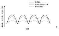
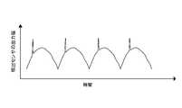
- FIG. 2 is a graph showing an example of a change over time in the output value of the detection sensor 60 when the dresser 40 is dressing the polishing surface 2a of the polishing pad 2.
- the vertical axis of FIG. 2 represents the output value of the detection sensor 60
- the horizontal axis of FIG. 2 represents time.
- the dressing disc 50 swings (reciprocates) in the radial direction on the polishing surface 2a of the polishing pad 2 with the turning motion of the dresser swing arm 55. Therefore, as shown in FIG. 2, the output value of the detection sensor 60 changes periodically as the dressing disk 50 swings.
- the cycle of the output value of the detection sensor 60 corresponds to the swing cycle of the dressing disk 50.
- the replacement time of the polishing pad 2 is determined as follows.
- the polishing device 1 includes a wear monitoring device 63 electrically connected to the detection sensor 60.
- the wear monitoring device 63 is configured to acquire a plurality of output values of the detection sensor 60 and determine a wear index value from the plurality of output values of the detection sensor 60. More specifically, the wear monitoring device 63 is configured to perform frequency analysis on a plurality of output values of the detection sensors 60 arranged along the time axis to determine the wear index value.
- the frequency analysis is a Fourier transform
- the wear monitoring device 63 applies the Fourier transform to a plurality of output values of the detection sensors 60 arranged along the time axis to create a power spectrum and power. It is configured to determine the wear index value, which is the peak value of the spectrum.
- the Fourier transform may be a fast Fourier transform (FFT).
- FFT fast Fourier transform
- wavelet analysis octave analysis and the like may be used.
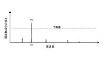
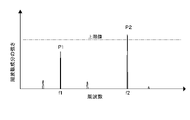
- FIG. 3 is a graph showing an example of the power spectrum created by the wear monitoring device 63.
- the horizontal axis of FIG. 3 is the frequency of fluctuation of the output value of the detection sensor 60 shown in FIG. 2, and the vertical axis of FIG. 3 is the intensity of the frequency component.
- the power spectrum has a peak value P1 due to the fluctuation of the dressing disk 50.
- the frequency f1 at which the peak value P1 appears corresponds to the frequency of fluctuation of the dressing disk 50. Therefore, the wear monitoring device 63 can identify the peak value P1 of the power spectrum caused by the swing of the dressing disk 50.
- the output value of the detection sensor 60 may include noise peculiar to the polishing device 1 and noise caused by foreign matter on the polishing pad 2. Due to these noises, as shown in FIG. 3, a plurality of peak values other than the peak value P1 appear on the power spectrum. According to the present embodiment, the power spectrum can be divided into a peak value P1 caused by friction between the dressing disc 50 and the polishing pad 2 and another peak value caused by noise. Therefore, the wear monitoring device 63 can monitor the time change of the friction between the dressing disc 50 and the polishing pad 2.
- the wear monitoring device 63 can perform noise processing on the output value of the detection sensor 60 to generate a corrected output value of the detection sensor 60.
- the wear monitoring device 63 measures or predicts in advance a noise component other than the contact between the polishing pad 2 and the workpiece W and the contact between the polishing pad 2 and the dresser 40, and detects or predicts the noise component as the output value of the detection sensor 60.
- the output value of the detection sensor 60 can be corrected. For example, the output value of the detection sensor 60 when there is no contact with the work piece W or the polishing pad 2 of the dresser 40, the output value of the detection sensor 60 when only the polishing head 7 is rotating, and the detection sensor during water polishing.
- the corrected output value of the detection sensor 60 can be created by filtering and calculation. Further, the corrected output value of the detection sensor 60 can be efficiently used to efficiently monitor the pad surface state by the sensor signal at a high SN.
- the peak value P1 of the power spectrum gradually decreases as the polishing pad 2 wears.
- the wear monitoring device 63 is configured to compare the peak value P1 with a predetermined lower limit value and issue an alarm signal when the peak value P1 falls below the lower limit value. This alarm signal causes the display device 63c of the wear monitoring device 63 to display information prompting the user to replace the polishing pad 2.
- the output value of the detection sensor 60 gradually changes as the polishing pad 2 wears. In other words, the output value of the detection sensor 60 reflects the wear of the polishing pad 2. Therefore, the wear monitoring device 63 can accurately determine the wear of the polishing pad 2 and the replacement time of the polishing pad 2 based on the wear index values obtained from the plurality of output values of the detection sensor 60.
- the wear monitoring device 63 is composed of at least one computer.
- the wear monitoring device 63 includes a storage device 63a in which the program is stored, and an arithmetic unit 63b that executes an operation according to an instruction included in the program.
- the storage device 63a includes a main storage device such as a random access memory (RAM) and an auxiliary storage device such as a hard disk drive (HDD) and a solid state drive (SSD).
- Examples of the arithmetic unit 63b include a CPU (central processing unit) and a GPU (graphic processing unit).
- the specific configuration of the wear monitoring device 63 is not limited to these examples.
- the wear monitoring device 63 may be integrally configured with the operation control unit 10. That is, the wear monitoring device 63 and the operation control unit 10 may be configured by at least one computer including a storage device in which the program is stored and an arithmetic unit that executes an operation according to an instruction included in the program.
- the wear monitoring device 63 in order to remove noise from the output value of the detection sensor 60, obtains a plurality of relative output values by subtracting the plurality of output values of the detection sensor 60 from the plurality of reference values. It may be configured to calculate and perform frequency analysis on a plurality of relative output values aligned along the time axis to determine the wear index value. In one embodiment, the frequency analysis is a Fourier transform (or fast Fourier transform), and the wear monitoring device 63 obtains a plurality of relative output values by subtracting the plurality of output values of the detection sensor 60 from the plurality of reference values. It may be configured to calculate and apply a Fourier transform (or fast Fourier transform) to a plurality of relative output values aligned along the time axis to create a power spectrum.
- a Fourier transform or fast Fourier transform
- the plurality of reference values are numerical values acquired during the operation of the polishing device 1.
- the plurality of reference values are a plurality of output values of the detection sensor 60 obtained when the dresser 40 first dresses the polishing pad 2. More specifically, after the new polishing pad 2 is attached to the polishing table 5, and before polishing the workpiece, the dresser 40 is used to supply pure water to the polishing surface 2a of the polishing pad 2.
- the initial dressing of the polishing pad 2 is executed, and a plurality of output values generated by the detection sensor 60 during the initial dressing are registered in the plurality of reference values.
- the wear monitoring device 63 stores a plurality of output values acquired from the detection sensor 60 as a plurality of reference values in the storage device 63a.
- FIG. 4 is a graph showing a plurality of reference values arranged along the time axis, a plurality of output values of the detection sensor 60, and a relative output value which is the difference between the reference value and the output value of the detection sensor 60.
- the vertical axis of FIG. 4 represents the reference value, the output value of the detection sensor 60, and the relative output value, and the horizontal axis of FIG. 4 represents time. It can be seen from FIG. 4 that the relative output value changes smoothly with the passage of time as compared with the output value of the detection sensor 60.
- FIG. 5 is a diagram showing a power spectrum obtained by applying a Fourier transform (or a fast Fourier transform) to the relative output values arranged along the time axis shown in FIG.
- a Fourier transform or a fast Fourier transform
- the wear monitoring device 63 calculates a plurality of relative output values by subtracting a plurality of output values of the detection sensor 60 from the plurality of reference values. ..
- the relative output value which is the difference between the reference value and the output value of the detection sensor 60, is a value from which noise has been removed.
- FIG. 6 is a graph showing another example of the change with time of the output value of the detection sensor 60 when the dresser 40 is dressing the polishing surface 2a of the polishing pad 2.
- the output value of the detection sensor 60 may temporarily and sharply increase. Such a rapid increase in the output value is caused by the presence of foreign matter (polishing debris, abrasive grains, etc.) on the polishing pad 2, partial peeling of the polishing pad 2, scratches in the polishing surface 2a of the polishing pad 2, and the like. It is caused by the abnormality of 2.
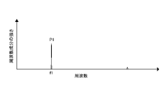
- FIG. 7 is a diagram showing a power spectrum obtained by applying a Fourier transform (or a fast Fourier transform) to a plurality of output values of the detection sensors 60 arranged along the time axis shown in FIG.
- the power spectrum has another peak value P2 due to an abnormality of the polishing pad 2 in addition to the peak value P1 at the frequency f1 corresponding to the fluctuation of the dressing disk 50.
- This peak value P2 appears at a frequency f2 different from the frequency f1 of the peak value P1.
- the wear monitoring device 63 compares this peak value P2 with a predetermined upper limit value, detects an abnormality of the polishing pad 2 when the peak value P2 exceeds a predetermined upper limit value, and notifies an alarm of the abnormality of the polishing pad 2. It is configured to generate a signal. According to the present embodiment, the polishing apparatus 1 can avoid adverse effects on polishing of the workpiece W due to an abnormality of the polishing pad 2 (for example, a foreign substance on the polishing pad 2 or a scratch on the polishing pad 2). can.
- FIGS. 6 and 7 may be combined with the embodiment described with reference to FIGS. 4 and 5.
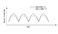
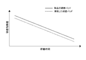
- FIG. 8 shows the time change of the polishing index value (thickness) output from the polishing progress detector 42 when the work piece is polished using the new polishing pad 2, and the work piece using the worn polishing pad 2. It is a graph which shows the time change of the polishing index value (thickness) output from the polishing progress detector 42 when polishing.
- the polishing index value when the polishing pad 2 is worn is generally shifted from the polishing index value when the polishing pad 2 is not worn. That is, even if the film thickness of the workpiece is the same, the polishing index value output from the polishing progress detector 42 may change depending on the wear of the polishing pad 2. In other words, the change in the polishing index value correlates with the wear of the polishing pad 2.
- the polishing progress detector 42 is an optical film thickness sensor or an eddy current type film thickness sensor
- the distance between the polishing progress detector 42 and the workpiece decreases as the polishing pad 2 wears.
- the polishing index value (film thickness) output from the polishing progress detector 42 can change.
- the torque current detector is used as the polishing progress detector 42 instead of the film thickness sensor
- the frictional force acting between the workpiece and the polishing pad 2 decreases as the polishing pad 2 wears.
- the polishing index value (torque current) output from the polishing progress detector 42 can change.
- the motion control unit 10 is configured to correct the polishing index value based on the wear index value.
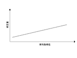
- the operation control unit 10 stores the correlation data as shown in FIG. 9 in advance in the storage device 10a.
- the correlation data shown in FIG. 9 shows an example of the correlation between the wear index value and the correction amount of the polishing index value.
- the correlation data is represented by a linear function, but the correlation data may be a quadratic function, a cubic function, or the like.
- the correlation data may be a data table showing the correlation between the wear index value and the correction amount of the polishing index value.
- Correlation data is created from past wear index values and corresponding polishing index values. Specifically, the wear index value obtained when a new polishing pad is used for polishing a plurality of workpieces until it wears below its usage limit, and the polishing index obtained under the same film thickness condition. Correlation data is created from the values.
- the motion control unit 10 acquires the wear index value sent from the wear monitoring device 63 while polishing the workpiece W, and determines the correction amount corresponding to the wear index value using the correlation data. Then, the operation control unit 10 acquires the polishing index value sent from the polishing progress detector 42 during the polishing of the workpiece W, adds the correction amount to the polishing index value (or subtracts the correction amount from the polishing index value). ) By doing so, the polishing index value is corrected.
- the operation control unit 10 controls the operation of the polishing device 1 based on the corrected polishing index value. For example, the motion control unit 10 determines the polishing end point at the time when the corrected polishing index value reaches a preset target value.
- FIGS. 8 and 9 may be appropriately combined with the embodiment described with reference to FIGS. 1 to 7.
- the output value of the detection sensor 60 it is possible to input the output value of the detection sensor 60 to the trained model by deep learning and output the surface state prediction of the polishing pad 2 from the trained model.
- the input to the trained model include the output value of the detection sensor 60, or the output value of the detection sensor 60 and parameters such as table torque and table rotation speed.
- the output from the trained model includes an index of the surface condition of the polishing pad 2 or a predicted value of evaluation.
- the wear monitoring device 63 can notify by an alert that the polishing pad 2 is recommended to be replaced when the predicted value approaches the reference value. It is also possible to output the normal use time prediction.
- a data set such as the usage time of the polishing pad 2 obtained in the process of actual polishing, the waveform of the output value of the detection sensor 60, and the replacement time of the polishing pad 2 is used.
- This data set can be selected and used for learning from a data set in which the polishing pad 2 is normally replaced, a data set in which an abnormality occurs during use, and a data set in which normal and abnormal are mixed.
- a camera that generates an image of the polished surface 2a of the polishing pad 2 may be installed on the dresser swing arm 55.
- the wear monitoring device 63 can observe the polished surface 2a by using the image of the polished surface 2a. For example, since the dresser swing arm 55 can swing and the polishing table 5 can rotate, the wear monitoring device 63 can observe an arbitrary region of the polishing surface 2a with a camera. The monitoring area of the polished surface 2a is determined in advance, and the wear monitoring device 63 periodically acquires an image of the polished surface 2a. The wear monitoring device 63 evaluates the change in the degree of wear of the polishing pad 2 from the image.
- the wear monitoring device 63 compares the change in the output value of the detection sensor 60 due to the wear of the polishing pad 2 with the image of the polishing surface 2a, and obtains the evaluation of the degree of wear of the polishing pad 2 by a plurality of indexes. It will be possible. For example, if both evaluation values indicate that it is time to exchange, it is possible to avoid an error due to the judgment of only one. Further, the wear monitoring device 63 can identify a portion where an abnormal waveform of the output signal of the detection sensor 60 is generated from the sensor signal, observe the portion, and determine an early countermeasure method.
- the present invention can be used in a technique for determining a replacement time of a polishing pad used in a polishing device for polishing workpieces such as wafers, substrates, and panels.
- Polishing device Polishing pad 2a Polishing surface 5 Polishing table 7 Polishing head 8 Polishing liquid supply nozzle 10 Operation control unit 14 Support shaft 16 Polishing head swing arm 18 Polishing head shaft 21 Table rotation motor 40 Dresser 42 Polishing progress detector 50 Dressing Disc 51 Dresser shaft 55 Dresser swing arm 58 Support shaft 60 Detection sensor 63 Wear monitoring device
Landscapes
- Engineering & Computer Science (AREA)
- Mechanical Engineering (AREA)
- Physics & Mathematics (AREA)
- Microelectronics & Electronic Packaging (AREA)
- Manufacturing & Machinery (AREA)
- Computer Hardware Design (AREA)
- General Physics & Mathematics (AREA)
- Power Engineering (AREA)
- Condensed Matter Physics & Semiconductors (AREA)
- Acoustics & Sound (AREA)
- Finish Polishing, Edge Sharpening, And Grinding By Specific Grinding Devices (AREA)
- Constituent Portions Of Griding Lathes, Driving, Sensing And Control (AREA)
- Grinding-Machine Dressing And Accessory Apparatuses (AREA)
- Mechanical Treatment Of Semiconductor (AREA)
Priority Applications (3)
| Application Number | Priority Date | Filing Date | Title |
|---|---|---|---|
| CN202180065798.6A CN116209543A (zh) | 2020-09-29 | 2021-08-05 | 研磨装置及研磨垫的更换时期的决定方法 |
| KR1020237013821A KR102772031B1 (ko) | 2020-09-29 | 2021-08-05 | 연마 장치, 및 연마 패드의 교환 시기를 결정하는 방법 |
| US18/246,366 US20230356350A1 (en) | 2020-09-29 | 2021-08-05 | Polishing apparatus and method of determining a time to replace polishing pad |
Applications Claiming Priority (2)
| Application Number | Priority Date | Filing Date | Title |
|---|---|---|---|
| JP2020163274A JP7421460B2 (ja) | 2020-09-29 | 2020-09-29 | 研磨装置、および研磨パッドの交換時期を決定する方法 |
| JP2020-163274 | 2020-09-29 |
Publications (1)
| Publication Number | Publication Date |
|---|---|
| WO2022070607A1 true WO2022070607A1 (ja) | 2022-04-07 |
Family
ID=80951343
Family Applications (1)
| Application Number | Title | Priority Date | Filing Date |
|---|---|---|---|
| PCT/JP2021/029120 Ceased WO2022070607A1 (ja) | 2020-09-29 | 2021-08-05 | 研磨装置、および研磨パッドの交換時期を決定する方法 |
Country Status (6)
| Country | Link |
|---|---|
| US (1) | US20230356350A1 (enExample) |
| JP (1) | JP7421460B2 (enExample) |
| KR (1) | KR102772031B1 (enExample) |
| CN (1) | CN116209543A (enExample) |
| TW (1) | TWI881169B (enExample) |
| WO (1) | WO2022070607A1 (enExample) |
Cited By (1)
| Publication number | Priority date | Publication date | Assignee | Title |
|---|---|---|---|---|
| CN115541703A (zh) * | 2022-09-27 | 2022-12-30 | 厦门理工学院 | 一种风电叶片连接处细小缺陷的检测方法和装置以及设备 |
Families Citing this family (4)
| Publication number | Priority date | Publication date | Assignee | Title |
|---|---|---|---|---|
| KR102748383B1 (ko) * | 2022-10-26 | 2024-12-31 | 주식회사 슈텍 | 화학기계적 연마장비용 검사 모니터링 장치, 이를 포함하는 화학기계적 연마장비 및 이의 제어방법 |
| JP2024067256A (ja) * | 2022-11-04 | 2024-05-17 | 株式会社荏原製作所 | 研磨装置、情報処理装置及びプログラム |
| CN117718876B (zh) | 2024-02-07 | 2024-06-18 | 华海清科股份有限公司 | 用于化学机械抛光的监测方法和化学机械抛光设备 |
| CN119141329A (zh) * | 2024-09-30 | 2024-12-17 | 东风汽车集团股份有限公司 | 一种汽车车身自动化精饰方法及系统 |
Citations (8)
| Publication number | Priority date | Publication date | Assignee | Title |
|---|---|---|---|---|
| JP2005022028A (ja) * | 2003-07-02 | 2005-01-27 | Tokyo Seimitsu Co Ltd | 研磨パッドのドレッシング装置及び該装置を有する加工装置 |
| JP2006255851A (ja) * | 2005-03-18 | 2006-09-28 | Ebara Corp | 研磨装置 |
| JP2009255250A (ja) * | 2008-04-18 | 2009-11-05 | Tokyo Seimitsu Co Ltd | 砥石成形状態判定装置及び砥石成形状態判定方法 |
| JP2010226007A (ja) * | 2009-03-25 | 2010-10-07 | Renesas Electronics Corp | 研磨工程制御方法および半導体ウエハ研磨システム |
| JP2014042968A (ja) * | 2012-08-28 | 2014-03-13 | Ebara Corp | ドレッシングプロセスの監視方法および研磨装置 |
| JP2017100254A (ja) * | 2015-12-03 | 2017-06-08 | 株式会社ディスコ | 研磨装置 |
| JP2020028955A (ja) * | 2018-08-23 | 2020-02-27 | 株式会社荏原製作所 | 研磨パッド高さを決定する方法、および研磨システム |
| KR20200043216A (ko) * | 2018-10-17 | 2020-04-27 | 주식회사 케이씨텍 | 화학 기계적 연마 장치의 컨디셔너 |
Family Cites Families (12)
| Publication number | Priority date | Publication date | Assignee | Title |
|---|---|---|---|---|
| US6191038B1 (en) * | 1997-09-02 | 2001-02-20 | Matsushita Electronics Corporation | Apparatus and method for chemical/mechanical polishing |
| JP2001079752A (ja) * | 1999-09-08 | 2001-03-27 | Hitachi Ltd | 化学的機械研磨装置およびこれを用いた半導体集積回路装置の製造方法 |
| KR100877383B1 (ko) * | 2001-11-13 | 2009-01-07 | 도요 고무 고교 가부시키가이샤 | 연마 패드 및 그 제조 방법 |
| JP5511600B2 (ja) | 2010-09-09 | 2014-06-04 | 株式会社荏原製作所 | 研磨装置 |
| CN102248486B (zh) * | 2011-07-25 | 2013-01-30 | 清华大学 | 抛光垫修整方法 |
| JP6030041B2 (ja) * | 2013-11-01 | 2016-11-24 | 株式会社荏原製作所 | 研磨装置および研磨方法 |
| CN204954631U (zh) * | 2015-09-21 | 2016-01-13 | 青岛理工大学 | 一种声发射和测力仪集成的砂轮堵塞检测清洗装置 |
| JP6357260B2 (ja) * | 2016-09-30 | 2018-07-11 | 株式会社荏原製作所 | 研磨装置、及び研磨方法 |
| JP6715153B2 (ja) * | 2016-09-30 | 2020-07-01 | 株式会社荏原製作所 | 基板研磨装置 |
| CN106826565B (zh) * | 2017-03-16 | 2018-11-02 | 中国人民解放军装甲兵工程学院 | 一种利用磨削力监控砂轮磨损与磨削烧伤的方法 |
| JP6829653B2 (ja) * | 2017-05-17 | 2021-02-10 | 株式会社荏原製作所 | 研磨装置および研磨方法 |
| JP7420530B2 (ja) * | 2018-10-31 | 2024-01-23 | 株式会社ノリタケカンパニーリミテド | ドレッシング面評価装置、ドレッシング装置、および、研削加工装置 |
-
2020
- 2020-09-29 JP JP2020163274A patent/JP7421460B2/ja active Active
-
2021
- 2021-08-05 KR KR1020237013821A patent/KR102772031B1/ko active Active
- 2021-08-05 US US18/246,366 patent/US20230356350A1/en active Pending
- 2021-08-05 CN CN202180065798.6A patent/CN116209543A/zh active Pending
- 2021-08-05 WO PCT/JP2021/029120 patent/WO2022070607A1/ja not_active Ceased
- 2021-09-23 TW TW110135246A patent/TWI881169B/zh active
Patent Citations (8)
| Publication number | Priority date | Publication date | Assignee | Title |
|---|---|---|---|---|
| JP2005022028A (ja) * | 2003-07-02 | 2005-01-27 | Tokyo Seimitsu Co Ltd | 研磨パッドのドレッシング装置及び該装置を有する加工装置 |
| JP2006255851A (ja) * | 2005-03-18 | 2006-09-28 | Ebara Corp | 研磨装置 |
| JP2009255250A (ja) * | 2008-04-18 | 2009-11-05 | Tokyo Seimitsu Co Ltd | 砥石成形状態判定装置及び砥石成形状態判定方法 |
| JP2010226007A (ja) * | 2009-03-25 | 2010-10-07 | Renesas Electronics Corp | 研磨工程制御方法および半導体ウエハ研磨システム |
| JP2014042968A (ja) * | 2012-08-28 | 2014-03-13 | Ebara Corp | ドレッシングプロセスの監視方法および研磨装置 |
| JP2017100254A (ja) * | 2015-12-03 | 2017-06-08 | 株式会社ディスコ | 研磨装置 |
| JP2020028955A (ja) * | 2018-08-23 | 2020-02-27 | 株式会社荏原製作所 | 研磨パッド高さを決定する方法、および研磨システム |
| KR20200043216A (ko) * | 2018-10-17 | 2020-04-27 | 주식회사 케이씨텍 | 화학 기계적 연마 장치의 컨디셔너 |
Cited By (1)
| Publication number | Priority date | Publication date | Assignee | Title |
|---|---|---|---|---|
| CN115541703A (zh) * | 2022-09-27 | 2022-12-30 | 厦门理工学院 | 一种风电叶片连接处细小缺陷的检测方法和装置以及设备 |
Also Published As
| Publication number | Publication date |
|---|---|
| CN116209543A (zh) | 2023-06-02 |
| TW202215521A (zh) | 2022-04-16 |
| KR20230078720A (ko) | 2023-06-02 |
| JP7421460B2 (ja) | 2024-01-24 |
| JP2022055703A (ja) | 2022-04-08 |
| US20230356350A1 (en) | 2023-11-09 |
| KR102772031B1 (ko) | 2025-02-26 |
| TWI881169B (zh) | 2025-04-21 |
Similar Documents
| Publication | Publication Date | Title |
|---|---|---|
| JP7421460B2 (ja) | 研磨装置、および研磨パッドの交換時期を決定する方法 | |
| JP5511600B2 (ja) | 研磨装置 | |
| US11325224B2 (en) | Method of monitoring a dressing process and polishing apparatus | |
| US6494765B2 (en) | Method and apparatus for controlled polishing | |
| TWI568534B (zh) | 墊片狀態化掃略力矩模式化以達成恆定移除率 | |
| TWI235690B (en) | Arrangement and method for conditioning a polishing pad | |
| CN102725832B (zh) | 用于补偿化学机械抛光耗材中的可变性的设备及方法 | |
| US6896583B2 (en) | Method and apparatus for conditioning a polishing pad | |
| US6702646B1 (en) | Method and apparatus for monitoring polishing plate condition | |
| US7163435B2 (en) | Real time monitoring of CMP pad conditioning process | |
| JP2017148931A (ja) | 研磨装置および研磨方法 | |
| JP2021517074A (ja) | パッドコンディショナカット速度監視 | |
| US20200039019A1 (en) | Apparatus and methods for chemical mechanical polishing | |
| WO2002038336A1 (en) | A method and apparatus for controlled polishing | |
| WO2024095997A1 (ja) | 研磨装置、情報処理装置及びプログラム | |
| JP2025004437A (ja) | 研磨方法、研磨装置、およびコンピュータに該研磨方法を実行させるためのプログラム | |
| KR20240113810A (ko) | 음향 캐리어 헤드 모니터링 |
Legal Events
| Date | Code | Title | Description |
|---|---|---|---|
| 121 | Ep: the epo has been informed by wipo that ep was designated in this application |
Ref document number: 21874910 Country of ref document: EP Kind code of ref document: A1 |
|
| ENP | Entry into the national phase |
Ref document number: 20237013821 Country of ref document: KR Kind code of ref document: A |
|
| NENP | Non-entry into the national phase |
Ref country code: DE |
|
| 122 | Ep: pct application non-entry in european phase |
Ref document number: 21874910 Country of ref document: EP Kind code of ref document: A1 |