WO2022070558A1 - ワーク搬送装置 - Google Patents
ワーク搬送装置 Download PDFInfo
- Publication number
- WO2022070558A1 WO2022070558A1 PCT/JP2021/026754 JP2021026754W WO2022070558A1 WO 2022070558 A1 WO2022070558 A1 WO 2022070558A1 JP 2021026754 W JP2021026754 W JP 2021026754W WO 2022070558 A1 WO2022070558 A1 WO 2022070558A1
- Authority
- WO
- WIPO (PCT)
- Prior art keywords
- holding
- magnet
- pump
- work
- unit
- Prior art date
- Legal status (The legal status is an assumption and is not a legal conclusion. Google has not performed a legal analysis and makes no representation as to the accuracy of the status listed.)
- Ceased
Links
Images





Classifications
-
- B—PERFORMING OPERATIONS; TRANSPORTING
- B65—CONVEYING; PACKING; STORING; HANDLING THIN OR FILAMENTARY MATERIAL
- B65G—TRANSPORT OR STORAGE DEVICES, e.g. CONVEYORS FOR LOADING OR TIPPING, SHOP CONVEYOR SYSTEMS OR PNEUMATIC TUBE CONVEYORS
- B65G54/00—Non-mechanical conveyors not otherwise provided for
- B65G54/02—Non-mechanical conveyors not otherwise provided for electrostatic, electric, or magnetic
-
- B—PERFORMING OPERATIONS; TRANSPORTING
- B65—CONVEYING; PACKING; STORING; HANDLING THIN OR FILAMENTARY MATERIAL
- B65G—TRANSPORT OR STORAGE DEVICES, e.g. CONVEYORS FOR LOADING OR TIPPING, SHOP CONVEYOR SYSTEMS OR PNEUMATIC TUBE CONVEYORS
- B65G47/00—Article or material-handling devices associated with conveyors; Methods employing such devices
- B65G47/74—Feeding, transfer, or discharging devices of particular kinds or types
- B65G47/90—Devices for picking-up and depositing articles or materials
- B65G47/91—Devices for picking-up and depositing articles or materials incorporating pneumatic, e.g. suction, grippers
-
- H—ELECTRICITY
- H01—ELECTRIC ELEMENTS
- H01M—PROCESSES OR MEANS, e.g. BATTERIES, FOR THE DIRECT CONVERSION OF CHEMICAL ENERGY INTO ELECTRICAL ENERGY
- H01M10/00—Secondary cells; Manufacture thereof
- H01M10/04—Construction or manufacture in general
- H01M10/0404—Machines for assembling batteries
-
- H—ELECTRICITY
- H01—ELECTRIC ELEMENTS
- H01M—PROCESSES OR MEANS, e.g. BATTERIES, FOR THE DIRECT CONVERSION OF CHEMICAL ENERGY INTO ELECTRICAL ENERGY
- H01M10/00—Secondary cells; Manufacture thereof
- H01M10/04—Construction or manufacture in general
- H01M10/0404—Machines for assembling batteries
- H01M10/0409—Machines for assembling batteries for cells with wound electrodes
-
- H—ELECTRICITY
- H01—ELECTRIC ELEMENTS
- H01M—PROCESSES OR MEANS, e.g. BATTERIES, FOR THE DIRECT CONVERSION OF CHEMICAL ENERGY INTO ELECTRICAL ENERGY
- H01M4/00—Electrodes
- H01M4/02—Electrodes composed of, or comprising, active material
- H01M4/04—Processes of manufacture in general
-
- H—ELECTRICITY
- H01—ELECTRIC ELEMENTS
- H01M—PROCESSES OR MEANS, e.g. BATTERIES, FOR THE DIRECT CONVERSION OF CHEMICAL ENERGY INTO ELECTRICAL ENERGY
- H01M10/00—Secondary cells; Manufacture thereof
- H01M10/04—Construction or manufacture in general
-
- Y—GENERAL TAGGING OF NEW TECHNOLOGICAL DEVELOPMENTS; GENERAL TAGGING OF CROSS-SECTIONAL TECHNOLOGIES SPANNING OVER SEVERAL SECTIONS OF THE IPC; TECHNICAL SUBJECTS COVERED BY FORMER USPC CROSS-REFERENCE ART COLLECTIONS [XRACs] AND DIGESTS
- Y02—TECHNOLOGIES OR APPLICATIONS FOR MITIGATION OR ADAPTATION AGAINST CLIMATE CHANGE
- Y02E—REDUCTION OF GREENHOUSE GAS [GHG] EMISSIONS, RELATED TO ENERGY GENERATION, TRANSMISSION OR DISTRIBUTION
- Y02E60/00—Enabling technologies; Technologies with a potential or indirect contribution to GHG emissions mitigation
- Y02E60/10—Energy storage using batteries
-
- Y—GENERAL TAGGING OF NEW TECHNOLOGICAL DEVELOPMENTS; GENERAL TAGGING OF CROSS-SECTIONAL TECHNOLOGIES SPANNING OVER SEVERAL SECTIONS OF THE IPC; TECHNICAL SUBJECTS COVERED BY FORMER USPC CROSS-REFERENCE ART COLLECTIONS [XRACs] AND DIGESTS
- Y02—TECHNOLOGIES OR APPLICATIONS FOR MITIGATION OR ADAPTATION AGAINST CLIMATE CHANGE
- Y02P—CLIMATE CHANGE MITIGATION TECHNOLOGIES IN THE PRODUCTION OR PROCESSING OF GOODS
- Y02P70/00—Climate change mitigation technologies in the production process for final industrial or consumer products
- Y02P70/50—Manufacturing or production processes characterised by the final manufactured product
Definitions
- This disclosure relates to a work transfer device.
- Laminated and laminated type batteries have been developed as batteries for automobiles.
- This battery has a structure in which a laminated electrode body in which a plurality of positive electrode plates and a plurality of negative electrode plates are alternately laminated with a separator interposed therebetween and an electrolytic solution are housed in a container.
- Patent Document 1 discloses that individual pieces of electrodes and separators are vacuum-adsorbed by a suction pad, transported to a stacking stage, and laminated on the stage. .. Such a transport method can be adopted not only for transporting the electrode plate and the separator but also for transporting other workpieces.
- This disclosure has been made in view of such circumstances, and one of the purposes thereof is to provide a technique for increasing the degree of freedom in designing a work transfer device.
- One aspect of the present disclosure is a work transfer device.
- This device includes a holding portion of a work, a plurality of holding heads having a vacuum pump for generating a holding force in the holding portion, and a transport truck for transporting the plurality of holding heads.
- the vacuum pump has a pump portion that is communicated with the holding portion and sucks the atmosphere through the holding portion or discharges the atmosphere to the holding portion, and a shaft portion that operates the pump portion by rotation.
- the shaft portion has a first magnet in which the north pole and the south pole are alternately magnetized around the shaft.
- the transport truck is a second magnet extending in the transport direction of the holding head, and alternately generates the magnetic force of the N pole and the magnetic force of the S pole in the transport direction, and is between the first magnet of the holding head to be transported.
- the magnetic poles of the portion of the second magnet that generates a magnetic force with respect to the first magnet are alternately switched to rotate the shaft portion, and the pump portion sucks or discharges the atmosphere to generate a holding force.
- the degree of freedom in designing the work transfer device can be increased.
- FIG. 5A is a perspective view of the vacuum pump
- FIG. 5B is a sectional perspective view of the vacuum pump. It is a figure explaining the mechanism which rotates a shaft part. It is a perspective view which shows the part including the holding release valve of a holding head in an enlarged manner.
- 8 (a) and 8 (b) are enlarged perspective views showing a portion including a delivery portion of the transport truck. It is a figure explaining the opening and closing operation of a holding release valve. It is a figure explaining the mechanism which rotates the shaft part in the work transfer apparatus which concerns on Embodiment 2.
- FIG. It is a perspective view of a part of the 2nd magnet provided in the work transfer apparatus which concerns on modification 2.
- FIG. 1 is a perspective view of the work transfer device 1 according to the first embodiment.
- FIG. 2 is an enlarged perspective view showing a part of the work transfer device 1. Note that FIG. 2 omits the illustration of the front plate 32 of the holding head 2.
- the work transfer device 1 includes a plurality of holding heads 2 and a transfer track 4. Each holding head 2 of the present embodiment sucks and holds the work W by the suction force generated by the suction of the atmosphere.
- the work W includes at least one of a battery electrode plate and a separator.
- the work W of the present embodiment is a unit laminated body 300 in which an electrode plate and a separator are laminated.
- the unit laminated body 300 is a constituent unit of the laminated electrode body 302. That is, a plurality of unit laminated bodies 300 are laminated to obtain a laminated electrode body 302.
- the work W is not limited to battery components such as an electrode plate, a separator, and a unit laminate 300.
- the transport truck 4 is a mechanism for transporting a plurality of holding heads 2. Each holding head 2 travels on the transport truck 4 with the transport truck 4 as a guide rail.
- the transport truck 4 has a known transport mechanism that transports each holding head 2.
- the transport truck 4 of the present embodiment has a known linear transport mechanism as an example. Specifically, the transport truck 4 has a rail portion 6 (stator) containing a plurality of coils (not shown) arranged in the extending direction. Further, each holding head 2 (movable element) has a transport magnet 8 at a position facing the coil while being suspended from the rail portion 6.
- the transport magnet 8 is, for example, a permanent magnet.
- the holding head 2 By applying the magnetic flux generated by energizing each coil to the transport magnet 8, thrust along the rail portion 6 and attractive force to the rail portion 6 are generated in the holding head 2. As a result, the holding head 2 travels along the rail portion 6.
- the holding head 2 has a roller 10 slidably in contact with the rail portion 6, and the roller 10 maintains a distance to the rail portion 6. Since the linear transfer mechanism is known, further detailed description thereof will be omitted.
- the transport truck 4 may be provided with a transport mechanism other than the linear transport mechanism that pulls the holding head 2 with, for example, a chain or the like.
- the transport truck 4 of the present embodiment is branched into a plurality of parts. Further, the transport truck 4 has a receiving unit 12 and a delivering unit 14.
- the holding head 2 receives the unit laminate 300 from the unit laminate manufacturing apparatus 100 at the receiving unit 12. Further, the holding head 2 discharges the unit laminated body 300 to the laminating device 200 at the delivery unit 14.
- the stacking device 200 is a device for manufacturing a laminated electrode body 302 by laminating a plurality of unit laminated bodies 300. Further, a plurality of delivery units 14 are provided for one receiving unit 12.
- the unit laminated body manufacturing apparatus 100 and the laminated apparatus 200 are schematically illustrated, and the illustration of a part of the structure is omitted. Further, the structure of each device is not limited to that shown in the figure.
- the transport truck 4 has a long annular structure in a predetermined direction, and a part of the ring is divided into two orbits extending in parallel. That is, the transport truck 4 has one first track 4a, and a second track 4b and a third track 4c branching from one end of the first track 4a. The other end of the second orbit 4b and the third orbit 4c branched from the first orbit 4a joins the first orbit 4a. That is, a branch point 4d is provided at one end of the first track 4a, and a confluence point 4e is provided at the other end of the first track 4a.
- a receiving unit 12 is arranged on the first track 4a.
- Two delivery portions 14 are arranged in the second track 4b and the third track 4c, respectively.
- the two delivery portions 14 are arranged in series.
- the shape of the transport truck 4 is not particularly limited, and may not have a branch point 4d or a confluence point 4e, or may have two or more branch points 4d or a confluence point 4e.
- the holding head 2 receives the unit laminate 300 as the work W from the unit laminate manufacturing apparatus 100 at the receiving unit 12, and travels on the first track 4a.
- the holding head 2 that has reached the branch point 4d to the second orbit 4b and the third orbit 4c is advanced by the control device 16 to either the second orbit 4b or the third orbit 4c.
- the control device 16 can switch the destination of the holding head 2 by controlling the energization of the coil built in the rail portion 6.
- the control device 16 is realized by elements and circuits such as a computer CPU and memory as a hardware configuration, and is realized by a computer program or the like as a software configuration, but in FIG. 1, it is realized by their cooperation. It is drawn as a functional block. It is well understood by those skilled in the art that this functional block can be realized in various ways by a combination of hardware and software.
- the holding head 2 traveling on the second orbit 4b or the third orbit 4c delivers the unit laminated body 300 to the laminating device 200 at the delivery unit 14.
- the holding head 2 that has released the unit laminate 300 further advances along the second orbit 4b or the third orbit 4c, returns from the confluence 4e to the first orbit 4a, and reaches the receiving unit 12 again.
- the receiving unit 12 receives the unit laminated body 300 and conveys it toward the delivery unit 14.
- the unit laminated body manufacturing apparatus 100 is, for example, a continuous drum type manufacturing apparatus in which a plurality of drums are combined, and each process such as cutting, heating, bonding, and laminating of an electrode body and a separator is executed by the drums. As a result, the unit laminate 300 can be manufactured at high speed and continuously.
- a plurality of individualized first electrode plates 304 are obtained by the first pole cutting drum 100a.
- the second pole cutting drum 100b provides a plurality of individualized second electrode plates 306.
- the first electrode plate 304 and the second electrode plate 306 are each preheated and supplied to the adhesive drum 100c. Further, the adhesive drum 100c is supplied with a continuum of the first separator 308 and a continuum of the second separator 310. Then, in the adhesive drum 100c, the continuous body of the first separator 308, the plurality of first electrode plates 304, the continuous body of the second separator 310, and the plurality of second electrode plates 306 are laminated and crimped in this order, and a plurality of units are pressed. A continuous laminate in which the laminate 300 is continuous is formed. The continuous laminate is separated into a plurality of unit laminates 300 by the separator cutting drum 100d. The individualized unit laminate 300 is conveyed to the receiving unit 12 and delivered to the holding head 2.
- the unit laminated body 300 is delivered from the holding head 2 to the laminating device 200 at the delivery unit 14.
- the laminating device 200 includes a laminating drum 200a.
- the laminated drum 200a sequentially conveys the plurality of unit laminated bodies 300 received from the holding head 2 to the laminated stage 200b and discharges them to the laminated stage 200b.
- the unit laminated body 300 is stacked on the laminated stage 200b, and the laminated electrode body 302 is obtained.
- the formed laminated electrode body 302 is taken out from the laminated stage 200b toward the apparatus of the next step.
- the unit laminated body 300 may be directly delivered from the holding head 2 to the laminated drum 200a, or a relay drum may be interposed between the holding head 2 and the laminated drum 200a.
- the transport truck 4 has a second magnet 18 extending in the transport direction D1 of the holding head 2.
- the second magnet 18 extends to a range in which the holding head 2 of the transport truck 4 holds the work W and travels. Further, the second magnet 18 is arranged so as to be close to the holding head 2 traveling on the transport truck 4. The structure and operation of the second magnet 18 will be described in detail later.
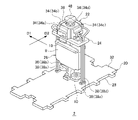
- FIG. 3 is a perspective view of the holding head 2 as viewed from diagonally above.
- FIG. 4 is a perspective view of the holding head 2 as viewed from diagonally below.
- 5 (a) is a perspective view of the vacuum pump 22, and
- FIG. 5 (b) is a sectional perspective view of the vacuum pump 22.
- the holding head 2 has a pad portion 20, a vacuum pump 22, a holding release valve 24, a support portion 26, a transport magnet 8, and a roller 10.
- the support portion 26 extends in a predetermined direction (for example, in the vertical direction), and the pad portion 20 is fixed to one end and the vacuum pump 22 is fixed to the other end. Further, the holding release valve 24, the transport magnet 8 and the roller 10 are fixed to the portion of the support portion 26 between the pad portion 20 and the vacuum pump 22.
- the pad portion 20 has a long flat plate shape in the orthogonal direction D2 orthogonal to the transport direction D1 of the holding head 2, and one main surface of the pad portion 20 faces the unit laminate manufacturing apparatus 100 in the receiving portion 12 and the delivery portion 14
- the posture is determined so as to face the stacking device 200.
- One of the main surfaces constitutes the work holding portion 28.
- the holding portion 28 of the present embodiment is composed of a suction surface that is sucked on the work W.
- the holding portion 28 is provided with a plurality of suction holes 30.
- the plurality of suction holes 30 are dispersedly arranged in the surface direction of the holding portion 28.
- the plurality of suction holes 30 are grouped into four groups: a first suction hole group 30a, a second suction hole group 30b, a third suction hole group 30c, and a fourth suction hole group 30d.
- the suction holes 30 are arranged at predetermined intervals in the orthogonal direction D2. Further, the first suction hole group 30a, the second suction hole group 30b, the third suction hole group 30c, and the fourth suction hole group 30d are arranged in this order from the front (downstream side) of the transport direction D1 of the holding head 2. I'm out.
- the suction holes 30 are connected to each other by a connecting pipe (not shown) extending in the orthogonal direction D2.
- the connecting pipe is connected to the vacuum pump 22 via a vacuum pipe 38 described later.
- a front plate 32 is provided on the main surface of the pad portion 20 opposite to the holding portion 28.
- the vacuum pump 22 is a device that generates a holding force in the holding portion 28.
- the vacuum pump 22 has a pump portion 34, a shaft portion 36, and a vacuum pipe 38.
- the vacuum pump 22 of the present embodiment is configured by a known diaphragm pump as an example.
- the structure of the vacuum pump 22 is not particularly limited as long as the holding force can be generated in the holding portion 28 by the rotation of the shaft portion 36.
- the vacuum pump 22 of the present embodiment has a plurality of pump units 34.
- the vacuum pump 22 has four pump units 34.
- Each pump unit 34 has a pump chamber 40, a diaphragm drive shaft 42, an intake port 44, and an exhaust port 46.
- the intake port 44 and the exhaust port 46 are connected to the pump chamber 40 and communicate with each other inside and outside the pump chamber 40.
- the pump chamber 40 has a diaphragm (not shown), and the diaphragm drive shaft 42 is connected to this diaphragm.
- the diaphragm drive shaft 42 is connected to the shaft portion 36.
- the shaft portion 36 operates the pump portion 34 by reciprocating the diaphragm drive shaft 42 by rotation.
- the shaft portion 36 is a so-called crankshaft.
- the diaphragm is elastically deformed by the reciprocating motion of the diaphragm drive shaft 42, whereby the atmosphere outside the pump chamber 40 is sucked into the pump chamber 40 from the intake port 44, and the atmosphere inside the pump chamber 40 is sucked into the pump chamber 40 from the exhaust port 46. It is discharged to the outside of 40.
- Each pump unit 34 is communicated with the holding unit 28 by a vacuum pipe 38, and sucks the atmosphere from each suction hole 30 of the holding unit 28.
- one end of the vacuum pipe 38 is connected to the intake port 44. Further, the other end of the vacuum pipe 38 is connected to the connecting pipe of the pad portion 20.
- the diaphragm drive shaft 42 of each pump unit 34 is connected to the same shaft unit 36. Therefore, each pump unit 34 generates a holding force by the rotation of the common shaft unit 36.
- the holding head 2 holds one work W by at least two pump units 34. Further, the holding head 2 holds a plurality of works W. As an example, of the four pump units 34, two pump units 34 hold one work W, and the remaining two pump units 34 hold another work W.
- the four pump units 34 and the first suction hole group 30a to the fourth suction hole group 30d are associated with each other on a one-to-one basis, and each suction hole group is separated from each other via the vacuum pipe 38.
- the pump unit 34 and the vacuum pipe 38 connected to the first suction hole group 30a will be referred to as a first pump unit 34a and a first vacuum pipe 38a.
- the pump portion 34 and the vacuum pipe 38 connected to the second suction hole group 30b are referred to as a second pump portion 34b and a second vacuum pipe 38b.
- the pump section 34 and the vacuum pipe 38 connected to the third suction hole group 30c are referred to as a third pump section 34c and a third vacuum pipe 38c.
- the pump unit 34 and the vacuum pipe 38 connected to the fourth suction hole group 30d are referred to as a fourth pump unit 34d and a fourth vacuum pipe 38d.
- the two works W held by each holding head 2 are arranged in the transport direction D1 of the holding head 2.
- the work W located forward in the transport direction D1 is sucked by the first suction hole group 30a and the second suction hole group 30b.
- the work W located rearward in the transport direction D1 is sucked by the third suction hole group 30c and the fourth suction hole group 30d.
- the work W located in the front is referred to as a front work W1
- the work W located in the rear is referred to as a rear work W2.
- the shaft portion 36 is provided with a first magnet 48.
- the first magnet 48 has a disk shape, and N poles and S poles are alternately magnetized around the axis of the shaft portion 36.
- the first magnet 48 is, for example, a permanent magnet.
- the shaft portion 36 can rotate by generating a magnetic force between the second magnet 18 and the first magnet 48 provided on the transport truck 4.
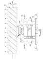
- FIG. 6 is a diagram illustrating a mechanism for rotating the shaft portion 36.
- the second magnet 18 is arranged close to the holding head 2 so that a magnetic force is generated between the second magnet 18 and the first magnet 48 of the held holding head 2 to be conveyed. Further, the second magnet 18 can alternately generate the magnetic force of the N pole and the magnetic force of the S pole in the transport direction D1 of the holding head 2. In the second magnet 18 of the present embodiment, N poles and S poles are alternately magnetized in the transport direction D1 of the holding head 2.
- the second magnet 18 is, for example, a permanent magnet.
- the magnetic poles of the portion of the second magnet 18 that generates a magnetic force with respect to the first magnet 48 alternate. Switch to.
- torque is generated in the shaft portion 36, and the first pump portion 34a to the fourth pump portion 34d suck the atmosphere through the holding portion 28 to generate a holding force in the holding portion 28.
- N poles and S poles are spirally formed around the rotation axis Ax extending in the transport direction D1 of the holding head 2. Further, the second magnet 18 rotates around the rotation axis Ax.
- the rotation of the second magnet 18 can be realized, for example, by the control device 16 controlling a motor (not shown) connected to the second magnet 18.
- the magnetic poles of can be switched alternately. Therefore, even when the holding head 2 is stopped, the rotation of the shaft portion 36 can be maintained and the holding force can be continuously generated in the holding portion 28.
- the rotation speed of the second magnet 18 and the transport speed of the holding head 2 are adjusted so that the magnetic pole of the portion that generates the magnetic force between the second magnet 18 and the first magnet 48 is not fixed. Further, the arrangement of the N pole and the S pole in each magnet, the positional relationship between the two magnets, and the like, which are necessary for rotating the shaft portion 36, can be appropriately set based on an experiment, a simulation, or the like by the designer. Further, the second magnet 18 shown in FIG. 1 is partially discontinuous in the range from the receiving unit 12 to the delivering unit 14. In this case, the length of the region where the second magnet 18 does not extend is the time from when the shaft portion 36 stops rotating until the holding force (adsorption force) of the holding portion 28 disappears, and the transport of the holding head 2. It is set according to the speed.
- the holding release valve 24 is a valve for releasing the holding force of the holding portion 28.
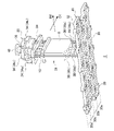
- FIG. 7 is an enlarged perspective view showing a portion of the holding head 2 including the holding release valve 24.
- 8 (a) and 8 (b) are enlarged perspective views showing a portion of the transport truck 4 including the delivery portion 14.
- FIG. 9 is a diagram illustrating an opening / closing operation of the holding release valve 24. Note that FIG. 8A omits the illustration of the laminating device 200.
- the holding release valve 24 is composed of, for example, a leaf spring, and is fixed to a long base plate 50 in the transport direction D1.
- the base plate 50 is fixed to the support portion 26 between the vacuum pump 22 and the pad portion 20.
- the vacuum pipe 38 is provided so as to penetrate the base plate 50.
- a branch pipe 52 connected to the vacuum pipe 38 is provided inside the base plate 50.
- One end of the branch pipe 52 is connected to the vacuum pipe 38, and the other end is opened to the outside of the base plate 50.
- the branch pipe 52 is connected to each of the first vacuum pipe 38a to the fourth vacuum pipe 38d.
- the branch pipe 52 connected to the first vacuum pipe 38a is referred to as a first branch pipe 52a
- the branch pipe 52 connected to the second vacuum pipe 38b is referred to as a second branch pipe 52b
- the third vacuum pipe is referred to as a third vacuum pipe.
- the branch pipe 52 connected to the 38c is referred to as a third branch pipe 52c
- the branch pipe 52 connected to the fourth vacuum pipe 38d is referred to as a fourth branch pipe 52d.
- two open ends of the branch pipes 52 are arranged on both sides of the base plate 50 in the orthogonal direction D2. Further, on each side of the base plate 50, the two open ends are arranged side by side in the transport direction D1. An open end of the first branch pipe 52a is arranged in front of the transport direction D1 on one side of the base plate 50. An open end of the third branch pipe 52c is arranged behind the transport direction D1 on one side of the base plate 50. An open end of the second branch pipe 52b is arranged in front of the transport direction D1 on the other side of the base plate 50. The open end of the fourth branch pipe 52d is arranged behind the transport direction D1 on the other side of the base plate 50.
- each branch pipe 52 is closed by the holding release valve 24.
- one long leaf spring is fixed to each side of the base plate 50 in the orthogonal direction D2 in the transport direction D1. Then, both ends of each leaf spring close the open end of the branch pipe 52, respectively, and function as a holding release valve 24.
- the work is switched between a closed state (a state in which the open end of the branch pipe 52 is closed) and an open state (a state in which the open end of the branch pipe 52 communicates with the atmosphere). W can be retained and released.
- the holding / releasing valve 24 that closes the open end of the first branch pipe 52a is referred to as the first holding / releasing valve 24a
- the holding / releasing valve 24 that closes the open end of the second branch pipe 52b is referred to as the second holding / releasing valve 24b
- the holding / releasing valve 24 that closes the open end of the third branch pipe 52c is referred to as a third holding / releasing valve 24c
- the holding / releasing valve 24 that closes the open end of the fourth branch pipe 52d is referred to as a fourth holding / releasing valve 24d.
- the front work W1 is switched between holding and releasing by the first holding release valve 24a and the second holding release valve 24b.
- the rear work W2 is switched between holding and releasing by the third holding release valve 24c and the fourth holding release valve 24d.
- Each holding release valve 24 has a third magnet 54 on a surface facing outward in the orthogonal direction D2.
- the third magnet 54 is, for example, a permanent magnet.
- the third magnet 54 is provided at both ends of the leaf spring constituting the first holding release valve 24a and the third holding release valve 24c.
- third magnets 54 are provided at both ends of the leaf springs constituting the second holding release valve 24b and the fourth holding release valve 24d.
- the transport truck 4 has a fourth magnet 56 at a position where the holding head 2 discharges the work W, that is, at the delivery portion 14.
- the fourth magnet 56 is, for example, an electromagnet.
- the energization of the fourth magnet 56 and the interruption of the energization are controlled by, for example, the control device 16.
- the fourth magnet 56 is arranged so as to generate a magnetic force with the third magnet 54 provided on the holding head 2 that has reached the delivery portion 14.
- the holding release valve 24 switches between the open / closed state due to the generation of a magnetic force between the third magnet 54 and the fourth magnet 56.
- a magnetic force that attracts each other is generated between the third magnet 54 and the fourth magnet 56.
- the leaf spring constituting the holding release valve 24 is elastically deformed in a direction away from the base plate 50. That is, the holding release valve 24 is in an open state.
- a gap G is formed between the base plate 50 and the leaf spring, and the open end of the branch pipe 52 communicates with the atmosphere.
- the atmosphere is sucked into the vacuum pipe 38 via the branch pipe 52, and the holding force (adsorption force) of the holding portion 28 is released.
- the holding force absorption force
- the leaf spring returns to the original state and closes the open end of the branch pipe 52. That is, the holding release valve 24 is in a closed state. As a result, the holding force of the holding portion 28 is restored.
- the fourth magnet 56 is arranged one by one at each delivery portion 14 so as to sandwich the holding head 2 in the orthogonal direction D2. Further, the two fourth magnets 56 arranged in each delivery portion 14 are arranged so as to be offset in the transport direction D1. Specifically, the fourth magnet 56 facing each open end of the first branch pipe 52a and the third branch pipe 52c is a fourth magnet facing each open end of the second branch pipe 52b and the fourth branch pipe 52d. It is displaced backward (upstream side) in the transport direction D1 from 56. Therefore, the release of the suction of the front work W1 by the first suction hole group 30a occurs before the release of the suction of the front work W1 by the second suction hole group 30b. Further, the release of the suction of the rear work W2 by the third suction hole group 30c occurs before the release of the suction of the rear work W2 by the fourth suction hole group 30d.
- the first holding release valve 24a first opens.
- vacuum fracture occurs in the front portion of the front work W1, and the front portion is handed over to the laminating device 200.
- the second holding release valve 24b opens.
- vacuum fracture occurs in the rear portion of the front work W1, and the rear portion is handed over to the laminating device 200.
- the control device 16 releases the energization to the fourth magnet 56 until the holding head 2 finishes passing through the delivery portion 14 on the upstream side.
- the holding head 2 advances to the delivery section 14 on the downstream side while sucking and holding the rear work W2. Then, the third holding release valve 24c is opened at the delivery portion 14 on the downstream side, the front portion of the rear work W2 is delivered to the laminating device 200, and then the fourth holding release valve 24d is opened.
- the rear portion of the side work W2 is delivered to the laminating device 200.
- the rear work W2 may be delivered to the laminating device 200 at the upstream delivery section 14, and the front work W1 may be delivered to the laminating device 200 at the downstream delivery section 14.
- the work transfer device 1 has a holding portion 28 of the work W, a plurality of holding heads 2 having a vacuum pump 22 for generating a holding force in the holding portion 28, and a plurality of holding portions.
- a transport truck 4 for transporting the head 2 is provided.
- the vacuum pump 22 has a pump unit 34 that communicates with the holding unit 28 and sucks the atmosphere through the holding unit 28, and a shaft portion 36 that operates the pump unit 34 by rotation.
- the shaft portion 36 has a first magnet 48 in which the north pole and the south pole are alternately magnetized around the shaft.
- the transport truck 4 is a second magnet 18 extending in the transport direction D1 of the holding head 2, and alternately generates the magnetic force of the N pole and the magnetic force of the S pole in the transport direction D1 of the holding head 2. It has a second magnet 18 arranged so as to generate a magnetic force with the first magnet 48. Then, the magnetic poles of the portion of the second magnet 18 that generates a magnetic force with respect to the first magnet 48 are alternately switched to rotate the shaft portion 36, whereby the pump portion 34 attracts the atmosphere to generate a holding force. Let me.
- the vacuum pump 22 is mounted on the holding head 2, and the holding force is generated in the holding portion 28 by rotating the shaft portion 36 by the action of the first magnet 48 and the second magnet 18. I'm letting you. For this reason, the vacuum piping and wiring required when the vacuum pump and the drive power supply are left outside to move the holding head, or when the drive power supply is left outside to move the holding head equipped with the vacuum pump. The laying can be omitted. Therefore, the degree of freedom in designing the work transfer device 1 can be increased.
- the second magnet 18 of the present embodiment rotates around the rotation axis Ax extending in the transport direction D1, and the N pole and the S pole are spirally formed around the rotation axis Ax. Then, as the second magnet 18 rotates, the magnetic poles of the portion of the second magnet 18 that generates a magnetic force with respect to the first magnet 48 are alternately switched. As a result, even if the holding head 2 is stopped, the holding force of the holding portion 28 can be maintained by continuing to rotate the shaft portion 36. For example, when the delivery surface of the work W and the holding portion 28 are both flat, it is desirable to stop the holding head 2 to transfer the work W in order to reduce the load applied to the work W at the time of delivery. ..
- the holding head 2 of the present embodiment capable of receiving the work W in the stopped state, the work W can be exchanged between the planes while reducing the load on the work W. If the work W is transferred between curved surfaces or between a curved surface and a flat surface, the work W can be transferred with a light load even while the holding head 2 is moved.
- the vacuum pump 22 of the present embodiment has a plurality of pump units 34.
- the holding portion 28 can be divided into a plurality of regions, and the holding force can be independently generated in each region. Further, the area of the holding portion 28 can be increased and the holding force can be increased. Further, each pump unit 34 operates by the rotation of the common shaft unit 36 to generate an suction force. As a result, it is possible to prevent the structure of the holding head 2 from becoming complicated due to the increase in the pump portion 34.
- the number of pump units 34 may be only one or a plurality of pump units other than four.
- the holding head 2 of the present embodiment holds one work W by at least two pump units 34. Further, the holding head 2 holds a plurality of works W. Specifically, the front work W1 is held by the first pump unit 34a and the second pump unit 34b. Further, the rear work W2 is held by the third pump unit 34c and the fourth pump unit 34d. By holding one work W by two or more pump units 34, the work W can be discharged in a plurality of stages. As a result, when the work W is delivered to the laminating device 200, the work W can be delivered more accurately. Further, the holding head 2 holds a plurality of work Ws, so that the throughput of the work transfer device 1 can be improved. One work W may be held by one pump unit 34 or three or more pump units 34. Further, the holding head 2 may hold one work W or three or more work Ws.
- the holding head 2 of the present embodiment has a holding release valve 24 that releases the holding force of the holding portion 28.
- the holding release valve 24 has a third magnet 54.
- the transport truck 4 has a fourth magnet 56 arranged so that a magnetic force is generated between the holding head 2 and the third magnet 54 at a position where the holding head 2 discharges the work W.
- the holding release valve 24 releases the holding force by switching the open / closed state by generating a magnetic force between the third magnet 54 and the fourth magnet 56.
- the holding force of the holding portion 28 can be released by a simple mechanism. Therefore, it is possible to suppress the increase in size of the vacuum pump 22 and thus the holding head 2.
- the transport truck 4 of the present embodiment is branched into a plurality of parts. As a result, the degree of freedom in arranging the transfer destination of the work W can be increased. Further, by arranging a device having a fast tact time at the branch source of the transport truck 4 and arranging a device having a slow tact time at each of the branch destinations, it is possible to avoid sacrificing the production speed of the device having a fast tact time. ..
- the work W of the present embodiment is a unit laminated body 300 in which an electrode plate and a separator are laminated.
- the transport truck 4 has a receiving unit 12 in which the holding head 2 receives the unit laminated body 300 from the unit laminated body manufacturing apparatus 100, and a delivery unit 14 in which the holding head 2 discharges the unit laminated body 300 to the laminating device 200. ..
- a plurality of delivery units 14 are provided for one receiving unit 12.
- the tact time of the unit laminated body manufacturing apparatus 100 (time required for manufacturing the unit laminated body 300 and handing it over to the holding head 2) is the tact time of the laminated body 200 (manufacturing of the laminated electrode body 302 and taking out from the laminated stage 200b). It tends to be shorter than the time required). Therefore, by providing a plurality of delivery units 14 for one receiving unit 12, the production speed of the laminated electrode body 302 can be improved. Further, a delivery section 14 is arranged at each branch destination of the transport truck 4. As a result, it is possible to suppress the lengthening of the transport truck 4 as compared with the case where a plurality of delivery portions 14 are arranged in series.
- the work transfer device 1 of the present embodiment it is possible to generate power by using the rotation of the shaft portion 36.
- the electric power obtained from this power generation can be used, for example, as a drive source for various sensors mounted on the holding head 2.
- the second embodiment has substantially the same configuration as the first embodiment except for the structure of the second magnet 18.
- the present embodiment will be mainly described with a configuration different from that of the first embodiment, and the common configuration will be briefly described or omitted.
- FIG. 10 is a diagram illustrating a mechanism for rotating the shaft portion 36 in the work transfer device 1 according to the second embodiment.
- the second magnet 18 of the present embodiment alternately generates the magnetic force of the N pole and the magnetic force of the S pole in the transport direction D1 of the holding head 2.
- N poles and S poles are alternately magnetized in the transport direction D1 of the holding head 2.
- the second magnet 18 of the present embodiment does not rotate around the rotation axis Ax. Even in such a configuration, the magnetic poles of the portion of the second magnet 18 that generates a magnetic force with respect to the first magnet 48 are alternately switched by the transport (movement) of the holding head 2.
- the shaft portion 36 can be rotated to operate the first pump portion 34a to the fourth pump portion 34d.
- the work transfer device 1 of the present embodiment can also increase the degree of freedom in designing the work transfer device 1. Further, in the work transfer device 1 of the present embodiment, it is necessary to keep moving the holding head 2 in order to maintain the holding force of the holding portion 28, but since the mechanism for rotating the second magnet 18 can be omitted, the work.
- the structure of the transport device 1 can be simplified.
- the pump unit 34 sucks the atmosphere through the holding unit 28 to generate an adsorption force as the holding force, but the present invention is not limited to this, and the pump unit 34 is applied to the holding unit 28.
- the holding force may be generated by discharging the atmosphere.
- the holding portion 28 is composed of a driving mechanism such as a cylinder driven by pressurization, and a gripping claw or the like that switches between gripping and releasing of the work W by this driving mechanism. Then, the exhaust port 46 and the holding portion 28 of the pump portion 34 are communicated with each other by the vacuum pipe 38.
- the pump unit 34 is driven, the atmosphere is discharged to the holding unit 28 and the drive mechanism is pressurized.
- the gripping claw grips the work W. That is, the pump unit 34 can generate a holding force in the holding unit 28 by discharging the atmosphere to the holding unit 28.
- the second magnet 18 of the first and second embodiments is a permanent magnet in which N pole and S pole are alternately magnetized in the transport direction D1 of the holding head 2, but the second magnet 18 is not limited to this. It may be composed of an electromagnet.
- FIG. 11 is a perspective view of a part of the second magnet 18 included in the work transfer device 1 according to the modified example 2.
- the second magnet 18 of the second modification has a structure in which a plurality of substantially U-shaped magnetic members 60 around which the coil 58 is wound are arranged in the transport direction D1.
- a magnetic force is generated in the first end portion 60a and the second end portion 60b by energizing the coil 58 wound around the intermediate portion.
- the first end portion 60a of each magnetic member 60 is arranged so as to be continuous in the transport direction D1 and to generate a magnetic force between the first magnet 48 of the holding head 2 to be transported.
- the coils 58 are energized so that the magnetic forces of different magnetic poles are generated at the adjacent first end portions 60a.
- the second magnet 18 can alternately generate the magnetic force of the N pole and the magnetic force of the S pole in the transport direction D1 of the holding head 2.
- the energization of each coil 58 is controlled by, for example, a control device 16.
- This disclosure can be used for work transfer equipment.
- 1 work transfer device 2 holding head, 4 transfer track, 12 receiving part, 14 delivery part, 18 second magnet, 22 vacuum pump, 24 holding release valve, 28 holding part, 34 pump part, 36 shaft part, 48 first Magnet, 54 3rd magnet, 56 4th magnet, W work.
Landscapes
- Engineering & Computer Science (AREA)
- Manufacturing & Machinery (AREA)
- Chemical & Material Sciences (AREA)
- Chemical Kinetics & Catalysis (AREA)
- Electrochemistry (AREA)
- General Chemical & Material Sciences (AREA)
- Mechanical Engineering (AREA)
- Feeding Of Articles By Means Other Than Belts Or Rollers (AREA)
- Specific Conveyance Elements (AREA)
- Manipulator (AREA)
Priority Applications (4)
| Application Number | Priority Date | Filing Date | Title |
|---|---|---|---|
| EP21874862.2A EP4223675B1 (en) | 2020-09-30 | 2021-07-16 | Workpiece conveyance device |
| US18/247,053 US12312186B2 (en) | 2020-09-30 | 2021-07-16 | Workpiece conveyance device |
| JP2022553488A JP7667790B2 (ja) | 2020-09-30 | 2021-07-16 | ワーク搬送装置 |
| CN202180066105.5A CN116323442B (zh) | 2020-09-30 | 2021-07-16 | 工件输送装置 |
Applications Claiming Priority (2)
| Application Number | Priority Date | Filing Date | Title |
|---|---|---|---|
| JP2020-164620 | 2020-09-30 | ||
| JP2020164620 | 2020-09-30 |
Publications (1)
| Publication Number | Publication Date |
|---|---|
| WO2022070558A1 true WO2022070558A1 (ja) | 2022-04-07 |
Family
ID=80949827
Family Applications (1)
| Application Number | Title | Priority Date | Filing Date |
|---|---|---|---|
| PCT/JP2021/026754 Ceased WO2022070558A1 (ja) | 2020-09-30 | 2021-07-16 | ワーク搬送装置 |
Country Status (5)
| Country | Link |
|---|---|
| US (1) | US12312186B2 (https=) |
| EP (1) | EP4223675B1 (https=) |
| JP (1) | JP7667790B2 (https=) |
| CN (1) | CN116323442B (https=) |
| WO (1) | WO2022070558A1 (https=) |
Families Citing this family (3)
| Publication number | Priority date | Publication date | Assignee | Title |
|---|---|---|---|---|
| KR102848553B1 (ko) * | 2021-11-10 | 2025-08-21 | 주식회사 엘지에너지솔루션 | 무지부의 열 주름을 방지할 수 있는 전극 시트 건조 장치 |
| DE102023123728A1 (de) | 2023-09-04 | 2025-03-06 | Mb Automation Gmbh & Co. Kg | Montagelinie und Verfahren zur Herstellung von Modulen oder Vorstufen von Modulen |
| KR20250179766A (ko) * | 2024-06-21 | 2025-12-31 | 삼성에스디아이 주식회사 | 전극 이송대, 전극 이송 장치 및 이를 포함하는 전극 제조 시스템 |
Citations (3)
| Publication number | Priority date | Publication date | Assignee | Title |
|---|---|---|---|---|
| JP2008282756A (ja) | 2007-05-14 | 2008-11-20 | Nec Tokin Corp | 積層構造電池の製造方法およびその製造装置 |
| JP2016220505A (ja) * | 2015-05-26 | 2016-12-22 | 日本電産サンキョー株式会社 | 磁気カップリング機構およびこれを備えたポンプ装置 |
| JP2019215977A (ja) * | 2018-06-12 | 2019-12-19 | 株式会社京都製作所 | 電池材料積層装置 |
Family Cites Families (8)
| Publication number | Priority date | Publication date | Assignee | Title |
|---|---|---|---|---|
| JPH08336274A (ja) * | 1995-06-07 | 1996-12-17 | Yatsu Kobo Kk | 磁気ねじ伝達装置 |
| JP2000342106A (ja) * | 1999-06-04 | 2000-12-12 | Guppy:Kk | エアポンプ |
| JP2009262287A (ja) * | 2008-04-25 | 2009-11-12 | Toyota Motor Corp | 吸着装置 |
| JP2012017776A (ja) * | 2010-07-06 | 2012-01-26 | Tsubakimoto Chain Co | 磁気式駆動力変換機構 |
| KR102013970B1 (ko) | 2011-09-30 | 2019-08-23 | 에이티에스 오토메이션 툴링 시스템즈 인코포레이티드 | 이동 요소에 진공을 제공하는 시스템 및 방법 |
| JP6402855B2 (ja) * | 2014-09-10 | 2018-10-10 | 澁谷工業株式会社 | 物品移載システム |
| IT201900003895A1 (it) * | 2019-03-18 | 2020-09-18 | Cft Spa | Apparato di trasporto |
| AT523217A1 (de) * | 2019-11-27 | 2021-06-15 | B & R Ind Automation Gmbh | Transporteinrichtung |
-
2021
- 2021-07-16 US US18/247,053 patent/US12312186B2/en active Active
- 2021-07-16 WO PCT/JP2021/026754 patent/WO2022070558A1/ja not_active Ceased
- 2021-07-16 CN CN202180066105.5A patent/CN116323442B/zh active Active
- 2021-07-16 JP JP2022553488A patent/JP7667790B2/ja active Active
- 2021-07-16 EP EP21874862.2A patent/EP4223675B1/en active Active
Patent Citations (3)
| Publication number | Priority date | Publication date | Assignee | Title |
|---|---|---|---|---|
| JP2008282756A (ja) | 2007-05-14 | 2008-11-20 | Nec Tokin Corp | 積層構造電池の製造方法およびその製造装置 |
| JP2016220505A (ja) * | 2015-05-26 | 2016-12-22 | 日本電産サンキョー株式会社 | 磁気カップリング機構およびこれを備えたポンプ装置 |
| JP2019215977A (ja) * | 2018-06-12 | 2019-12-19 | 株式会社京都製作所 | 電池材料積層装置 |
Non-Patent Citations (1)
| Title |
|---|
| See also references of EP4223675A4 |
Also Published As
| Publication number | Publication date |
|---|---|
| CN116323442B (zh) | 2026-01-02 |
| JPWO2022070558A1 (https=) | 2022-04-07 |
| CN116323442A (zh) | 2023-06-23 |
| EP4223675A4 (en) | 2024-03-20 |
| US20230406649A1 (en) | 2023-12-21 |
| EP4223675A1 (en) | 2023-08-09 |
| US12312186B2 (en) | 2025-05-27 |
| JP7667790B2 (ja) | 2025-04-23 |
| EP4223675B1 (en) | 2024-10-16 |
Similar Documents
| Publication | Publication Date | Title |
|---|---|---|
| WO2022070558A1 (ja) | ワーク搬送装置 | |
| JP6819652B2 (ja) | 電池材料積層装置 | |
| TWI620364B (zh) | 片積層治具、積層製品的製造方法以及片狀二次電池的製造方法 | |
| WO2019220875A1 (ja) | 電池材料積層装置 | |
| CN103460483B (zh) | 装袋电极的制造装置及装袋电极的制造方法 | |
| CN103460482A (zh) | 装袋电极的制造装置及装袋电极的制造方法 | |
| CN103460481A (zh) | 装袋电极的制造装置及装袋电极的制造方法 | |
| CN115836420B (zh) | 层叠装置 | |
| CN114267863A (zh) | 片材输送装置 | |
| WO2020079991A1 (ja) | 電池材料積層装置 | |
| JP2025033347A (ja) | 電極積層装置 | |
| TWI796793B (zh) | 真空積層裝置及積層體的製造方法 | |
| EP4656564A1 (en) | Hybrid shuttle for planar and long stator linear motors | |
| WO2022009594A1 (ja) | セパレータ切断装置およびセパレータ切断方法 | |
| JP7786807B2 (ja) | 搬送装置、加工システム、制御方法及び物品の製造方法 | |
| JP2025508040A (ja) | エネルギセルのセグメントを積層するセル積層設備、この種のセル積層設備を制御する方法、セル積層設備の又はセル積層設備内の区分装置、及びセル積層設備内でセル積層体を製造する際の区分方法 | |
| CN116323446A (zh) | 层叠装置 | |
| JP2022014014A (ja) | 部材を搬送する方法および搬送装置 | |
| JP2020063141A (ja) | ワーク積層装置 | |
| KR20200053760A (ko) | 기판 반송 장치 | |
| JPH0488809A (ja) | 磁気浮上式搬送装置 | |
| JPS63209405A (ja) | リニアモ−タ駆動搬送体の制御装置 | |
| JPH08301432A (ja) | ワーク分離装置 |
Legal Events
| Date | Code | Title | Description |
|---|---|---|---|
| 121 | Ep: the epo has been informed by wipo that ep was designated in this application |
Ref document number: 21874862 Country of ref document: EP Kind code of ref document: A1 |
|
| ENP | Entry into the national phase |
Ref document number: 2022553488 Country of ref document: JP Kind code of ref document: A |
|
| WWE | Wipo information: entry into national phase |
Ref document number: 202347029738 Country of ref document: IN |
|
| NENP | Non-entry into the national phase |
Ref country code: DE |
|
| ENP | Entry into the national phase |
Ref document number: 2021874862 Country of ref document: EP Effective date: 20230502 |
|
| WWG | Wipo information: grant in national office |
Ref document number: 18247053 Country of ref document: US |