WO2022070247A1 - 情報処理システム、情報処理方法およびプログラム - Google Patents
情報処理システム、情報処理方法およびプログラム Download PDFInfo
- Publication number
- WO2022070247A1 WO2022070247A1 PCT/JP2020/036859 JP2020036859W WO2022070247A1 WO 2022070247 A1 WO2022070247 A1 WO 2022070247A1 JP 2020036859 W JP2020036859 W JP 2020036859W WO 2022070247 A1 WO2022070247 A1 WO 2022070247A1
- Authority
- WO
- WIPO (PCT)
- Prior art keywords
- delay
- delay amount
- computer system
- user
- computer
- Prior art date
- Legal status (The legal status is an assumption and is not a legal conclusion. Google has not performed a legal analysis and makes no representation as to the accuracy of the status listed.)
- Ceased
Links
Images






Classifications
-
- H—ELECTRICITY
- H04—ELECTRIC COMMUNICATION TECHNIQUE
- H04L—TRANSMISSION OF DIGITAL INFORMATION, e.g. TELEGRAPHIC COMMUNICATION
- H04L43/00—Arrangements for monitoring or testing data switching networks
- H04L43/08—Monitoring or testing based on specific metrics, e.g. QoS, energy consumption or environmental parameters
- H04L43/0852—Delays
-
- H—ELECTRICITY
- H04—ELECTRIC COMMUNICATION TECHNIQUE
- H04L—TRANSMISSION OF DIGITAL INFORMATION, e.g. TELEGRAPHIC COMMUNICATION
- H04L43/00—Arrangements for monitoring or testing data switching networks
- H04L43/20—Arrangements for monitoring or testing data switching networks the monitoring system or the monitored elements being virtualised, abstracted or software-defined entities, e.g. SDN or NFV
Definitions
- the present invention relates to an information processing system, an information processing method, and a program technology.
- FIG. 21 is a diagram showing a configuration example of an information processing system in the prior art.
- the information processing system includes a user system 900 (900a, 900b, ... 900z), a computer system 910 (910a, 910b, ... 910z), and a central computer system 920.
- the user system 900 includes an input / output device 901 (901a, 901b, ... 901z) such as an image display device, a keyboard, a mouse, and a tablet, and an input / output management device 902 (902a, 902b, ... 902z) that manages the input / output device 901. And an input / output signal transmission / reception device 903 (903a, 903b, ... 903z) having a communication function is provided.
- an input / output device 901 (901a, 901b, ... 901z) such as an image display device, a keyboard, a mouse, and a tablet
- an input / output management device 902 (902a, 902b, ... 902z) that manages the input / output device 901.
- an input / output signal transmission / reception device 903 (903a, 903b, ... 903z) having a communication function is provided.
- the computer system 910 includes an input / output signal transmission / output device 911 (911a, 911b, ... 911z) that transmits / receives information to / from the user system 900, a computer 912 (912a, 912b, ... 912z) that performs information processing, and a central computer system 920. It is provided with an input / output signal transmission / reception device 913 (913a, 913b, ... 913z) for transmitting / receiving information to / from.
- the central computer system 920 includes a signal transmission / reception device 921 having a communication function and a central computer 922 that adjusts and controls the entire contents.
- the user system 900 and the computer system 910 are connected by a first network, and the computer system 910 and the central computer system 920 are connected by a second network.
- the network may be wired or wireless.
- the delay amount generated between the user system 900a and the computer system 910a is Tfa
- the delay amount generated between the user system 900b and the computer system 910b is Tfb
- the amount of delay that occurs between 910z and 910z is Tfz.
- the amount of delay generated between the computer system 910a and the central computer system 920 is Tba
- the amount of delay generated between the computer system 910b and the central computer system 920 is Tbb
- Tfa, Tfb, ..., and Tfz generally do not occur in the same delay environment between devices located between different bases, so the delay amounts are often different from each other. Further, Tba, Tbb, ..., And Tbz often have different delay amounts from each other for the same reason.
- FIG. 22 is a diagram showing a delay amount for each user in the prior art.
- each user individually realizes the lowest possible delay, so that there is a delay difference between users when using the same content among a plurality of users. rice field.
- it is difficult to hold an event in an equal environment in a highly competitive event because there are many contents that are advantageous to users with a small amount of delay.
- a packet switching network such as the Internet is used in the network, the amount of delay fluctuates drastically with the passage of time due to the service provider and external factors.
- an object of the present invention is to provide a technique capable of reducing the difference in the amount of delay between users.
- At least one of the connection between the input / output device and the computer and the connection between the computer and the central computer is connected via a network, and a plurality of users input / output the same content via the network.
- An information processing system used by the device based on a delay measuring device that measures the amount of transmission delay generated between the input / output device and the central computer for each user, and the measured transmission delay amount. It is an information processing system including a delay adjusting device that adjusts the difference in the transmission delay amount between users so as to keep it within a predetermined value.
- At least one of the connection between the input / output device and the computer and the connection between the computer and the central computer is connected via a network, and a plurality of users input / output the same content via the network.
- An information processing method in an information processing system used by an apparatus in which a delay measuring apparatus measures a transmission delay amount generated between the input / output apparatus and the central computer for each user, and a delay adjusting apparatus is used. It is an information processing method that adjusts the difference in the transmission delay amount between the users based on the measured transmission delay amount so as to keep it within a predetermined value.
- connection between the input / output device and the computer and the connection between the computer and the central computer is connected via a network, and a plurality of users input / output the same content via the network.
- the computer of the delay adjusting device in the information processing system used by the device is made to measure the transmission delay amount generated between the input / output device and the central computer for each user, and based on the measured transmission delay amount.
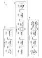
- FIG. 1 is a diagram showing an example of the overall configuration of the information processing system according to the present embodiment.
- the information processing system 1 includes a user system 3 (3-1, 3-2, ..., 3-n (n is an integer of 2 or more)) and a computer system 4 (4-1, 4-2). , ..., 4-n), a central computer system 5, and a delay adjusting device 6.
- the user system 3 includes, for example, an input / output device 31 (31-1, 31-2, ..., 31-n), an input / output management device 32 (32-1, 32-2, ..., 32-n), and delay control.
- the apparatus 33 (33-1, 33-2, ..., 33-n) and the input / output signal transmission / reception device 34 (34-1, 34-2, ..., 34-n) are provided.
- Computer system 4 for example, input / output signal transmission / reception device 41 (41-1, 41-2, ..., 41-n), first delay control device 42 (42-1, 42-2, ..., 42-n). , Computer 43 (43-1, 43-2, ..., 43-n), second delay control device 44 (44-1, 44-2, ..., 44-n), and signal transmitter / receiver 45 (45-). 1, 45-2, ..., 45-n).
- the user system 3 and the computer system 4 are connected by a first network NW1 (NW1-1, NW1-2, ..., NW1-n).
- the first network NW1 may be a wired network or a wireless network, and the physical topology and the logical topology may be arbitrary, and may be a circuit-switched network or a packet-switched network. Further, the communication methods of the first networks NW1-1, NW1-2, ..., NW1-n may be the same or different.
- the first network NW1 is, for example, the Internet, and may include a communication network and a roaming data transfer network. The communication network and the roaming data transfer network may be integrated or separate. Further, the first network NW1 may have an authentication function.
- the central computer system 5 includes, for example, a signal transmission / reception device 51 (51-1, 51-2, ..., 51-n), a delay control device 52 (52-1, 52-2, ..., 52-n), and a center.
- a computer 53 is provided.
- the computer system 4 and the central computer system 5 are connected by a second network NW2 (NW2-1, NW2-2, ..., NW2-n).
- the second network NW2 may be a wired network or a wireless network, and the physical topology and the logical topology may be arbitrary, and may be a circuit-switched network or a packet-switched network. Further, the communication methods of the second networks NW2-1, NW2-2, ..., NW2-n may be the same or different.
- the delay control device 33 of the user system 3 is connected to the delay adjustment device 6, the first delay control device 42 of the computer system 4 is connected, and the second delay control device 44 of the computer system 4 is connected. , The delay control device 52 of the central computer system 5 is connected.
- the input / output device 31 is, for example, an image display device, a keyboard, a mouse, a game controller, a tablet, a scanner, a printer, a speaker, and the like.
- the input / output device 31 is connected to the input / output management device 32.
- the input / output management device 32 manages the output of information to the input / output device 31, the output of information from the input / output device 31, and the like.
- the input / output management device 32 is connected to the delay control device 33.
- the delay control device 33 together with the first delay control device 42 of the computer system 4, is a transmission delay generated between the user system 3 and the computer system 4, which is a delay amount generated between the input / output device 31 and the computer 43.
- the amount (hereinafter, “the amount of transmission delay generated between A and B” is referred to as “the amount of delay between A and B") is measured, and the delay information indicating the measured delay amount is output to the delay adjusting device 6. do.
- the delay control device 33 adjusts the delay amount between the user system 3 and the computer system 4 according to the control of the delay adjusting device 6.
- the delay control device 33 is connected to the input / output signal transmission / reception device 34.
- the input / output signal transmission / reception device 34 receives a signal from the computer system 4, and outputs the received signal to the input / output management device 32 via the delay control device 33.
- the input / output signal transmission / reception device 34 acquires the signal output by the input / output management device 32 via the delay control device 33, and transmits the acquired signal to the computer system 4.
- the signal from the computer system 4 includes, for example, an image signal, an audio signal, and the like.
- the signal from the user system 3 to the computer system 4 includes, for example, operation information such as a keyboard and a mouse.
- the computer system 4 is, for example, a data center, a communication building, a server room, or the like.
- the input / output signal transmission / reception device 41 receives the signal output by the user system 3, and outputs the received signal to the computer 43 via the first delay control device 42.
- the input / output signal transmission / reception device 41 acquires the signal output by the computer 43 via the delay control device 33, and transmits the acquired signal to the user system 3.
- the input / output signal transmission / reception device 41 is connected to the first delay control device 42.
- the first delay control device 42 together with the delay control device 33 of the user system 3, measures the delay amount between the user system 3 and the computer system 4, which is the delay amount between the input / output device 31 and the computer 43. Then, the delay information indicating the measured delay amount is output to the delay adjusting device 6. The first delay control device 42 adjusts the delay amount between the user system 3 and the computer system 4 according to the control of the delay adjusting device 6. The first delay control device 42 is connected to the computer 43.
- the computer 43 processes and controls the content according to the signal output by the user system 3.
- the computer 43 may be a physical computer or a logical computer (virtual computer).
- a virtual computer for example, a CPU, GPU (Graphics Processing Unit), memory, storage, and the like are virtualized.
- the computer 43 may be a game device.
- the second delay control device 44 together with the delay control device 52 of the central computer system 5, determines the delay amount between the computer system 4 and the central computer system 5, which is the delay amount between the computer 43 and the central computer 53. The measurement is performed, and the delay information indicating the measured delay amount is output to the delay adjusting device 6. The second delay control device 44 adjusts the delay amount between the computer system 4 and the central computer system 5 according to the control of the delay adjusting device 6. The second delay control device 44 is connected to the signal transmission / reception device 45.
- the signal transmission / reception device 45 transmits the signal output by the computer 43 to the central computer system 5.
- the signal transmission / reception device 45 receives a signal from the central computer system 5, and outputs the received signal to the computer 43 via the second delay control device 44.
- the signal transmission / reception device 51 receives the signal transmitted by the computer system 4, and outputs the received signal to the central computer 53 via the delay control device 52.
- the signal transmission / reception device 51 acquires a signal from the central computer 53 via the delay control device 52, and transmits the acquired signal to the computer system 4.
- the signal transmission / reception device 51 is connected to the delay control device 52.
- the delay control device 52 together with the second delay control device 44 of the computer system 4, measures the delay amount between the computer system 4 and the central computer system 5, which is the delay amount between the computer 43 and the central computer 53. Then, the delay information indicating the measured delay amount is output to the delay adjusting device 6. The delay control device 52 adjusts the delay amount between the computer system 4 and the central computer system 5 according to the control of the delay adjustment device 6. The delay control device 52 is connected to the central computer 53.
- the central computer 53 is, for example, a server.
- the central computer 53 communicates with each computer and performs processing according to the content.
- the central computer 53 sets the Room, sets the user group, and the like.
- the Room and user groups will be described later.
- a "delay control device” is provided in both communication sections, but the configuration is not limited to this, and the delay is limited to only one direction. In the case of a usage case where adjustment is not performed (video distribution, etc.), the configuration may omit the "delay control device" on the transmitting side.
- the "delay control device” is not limited to a single physical device, and may be implemented as an in-device functional unit connected to the vicinity of the delay control device.
- the in-device function unit is, for example, implemented as an internal function of the signal transmission / reception device 45, logically implemented as an application inside the computer 43, and the like.
- the delay adjusting device 6 acquires user information from the user system 3 and the like, and transmits the acquired user information to the central computer system 5.
- the user information may include, for example, information such as the number of users, the Room used or selected by the user, and the user group to which the user belongs.
- the delay adjusting device 6 instructs each delay control device (33, 42, 44, 52) to measure the delay amount for each user, and acquires the measurement result.
- the delay adjusting device 6 adjusts the delay amount based on the acquired delay amount for each user.
- the computer 43, the central computer 53, and the delay adjusting device 6 are configured by using a processor such as a CPU (Central Processing Unit) and a memory. All or part of each function of the computer 43, the central computer 53, and the delay adjusting device 6 is equipped with hardware such as an ASIC (Application Specific Integrated Circuit), a PLD (Programmable Logic Device), and an FPGA (Field Programmable Gate Array). It may be realized by using.
- the above program may be recorded on a computer-readable recording medium.
- Computer-readable recording media include, for example, flexible disks, magneto-optical disks, ROMs, CD-ROMs, portable media such as semiconductor storage devices (for example, SSD: Solid State Drive), hard disks and semiconductor storage built in computer systems. It is a storage device such as a device.
- the above program may be transmitted over a telecommunication line.
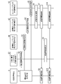
- FIG. 2 is a sequence diagram showing an example of a procedure for measuring the delay amount according to the present embodiment.
- the delay adjusting device 6 measures, for example, the total delay amount of the user system 3 to the computer system 4 to the central computer system 5 in advance by each delay control device (33, 42, 44, 52) before starting to use the computer 43. do.
- the delay adjusting device 6 transmits a delay amount measurement instruction to each delay control device (33, 42, 44, 52) (step S1).
- Each delay control device receives a delay amount measurement instruction (steps S2 to S5).
- the first delay control device 42 of the computer system 4 transmits a delay amount measurement instruction to the user system 3 via the input / output signal transmission / reception device 41 according to the control of the delay adjustment device 6, and also measures and counts the delay amount.
- the delay control device 33 of the user system 3 receives the delay amount measurement instruction
- the delay control device 33 transmits the reception information indicating the reception to the computer system 4 via the input / output signal transmission / reception device 34.
- the first delay control device 42 receives the received information from the user system 3 via the input / output signal transmission / reception device 41, and ends the measurement count of the delay amount (step S6).
- the measurement may be performed by the delay control device 33 on the user system 3 side.
- the delay amount is, for example, the delay time between the delay control device 33 of the user system 3 and the first delay control device 42 of the computer system 4.
- the first delay control device 42 or the delay control device 33 transmits the measured delay amount information to the delay adjusting device 6 (step S7).
- the delay adjusting device 6 receives the measured delay amount information (step S8).
- the second delay control device 44 of the computer system 4 transmits a delay amount measurement instruction to the central computer system 5 via the signal transmission / reception device 45 according to the control of the delay adjustment device 6, and the delay amount. Starts the measurement count of.
- the delay control device 52 of the central computer system 5 receives the delay amount measurement instruction, the delay control device 52 transmits the received information indicating the reception to the computer system 4 via the signal transmission / reception device 51.
- the second delay control device 44 receives the received information from the central computer system 5 via the signal transmission / reception device 45 central computer system 5, and ends the measurement count of the delay amount (step S9).
- the measurement may be performed by the delay control device 52 on the central computer system 5.
- the delay amount is, for example, the delay time between the second delay control device 44 of the computer system 4 and the delay control device 52 of the central computer system 5.
- the second delay control device 44 or the delay control device 52 transmits the measured delay amount information to the delay adjusting device 6 (step S10).
- the delay adjusting device 6 receives the measured delay amount information and stores each received delay amount information (step S11).
- each delay control device may perform periodic execution with a time-out, and sequentially send the result to the delay adjustment device 6. Further, each delay control device may omit sending information to the delay adjusting device 6 if the measurement result has a difference within an allowable range (for example, less than 1 (ms)) as compared with the past result.
- an allowable range for example, less than 1 (ms)
- the delay amount is measured for all the user systems 3 and the computer system 4 connected to the contents handled by the central computer 53.
- FIG. 3 is a diagram showing an example of the total delay amount before adjustment of the user system 3 to the computer system 4 to the central computer system 5.
- the horizontal axis is the user and the vertical axis is the delay amount.
- the delay amount between the user system 3-1 and the computer system 4-1 is Tfa (for example, 20 (ms))
- the delay amount between the user system 3-2 and the computer system 4-2 is Tfb (for example, 20 (ms)).
- Tfz for example, 40 (ms)
- the delay amount between the computer system 4-1 and the central computer system 5 is Tba (for example, 30 (ms)), and the delay amount between the computer system 4-2 and the central computer system 5 is Tbb (for example, 40 (ms)).
- Tbz for example, 20 (ms)
- FIG. 4 is a sequence diagram showing an example of a procedure for adjusting the delay amount according to the present embodiment.
- the delay adjusting device 6 calculates the total delay amount of the user system 3 to the computer system 4 to the central computer system 5 based on the delay amount information received from each delay control device (step S51).
- the delay adjustment device 6 calculates the adjustment delay amount based on the delay amount information received from each delay control device and the calculated total delay amount (step S52).
- the delay adjusting device 6 transmits the calculated adjustment delay amount information to each delay control device (step S53).
- Each delay control device receives adjustment delay amount information (steps S54 to S57).
- the adjustment delay amount information may include information indicating which delay control device adjusts the delay amount.
- the delay adjusting device 6 may transmit the adjustment delay amount information to the delay control device that adjusts the delay amount.
- Each delay control device adjusts the delay amount based on the received adjustment delay amount information (steps S58 to S61).
- FIG. 5 is a diagram showing an example of the adjusted delay amount.
- the horizontal axis is the user and the vertical axis is the delay amount.
- the delay adjusting device 6 adjusts the amount of delay between the user system 3 and the computer system 4. Based on the measurement information of the amount of delay between all user systems, computer system and central computer system, the delays of "between central computer and computer” and “between computer and user system” are within the allowable range among all users. Calculate the adjustment delay amount so that it fits within. Based on the calculated adjustment delay amount for each user, it is set to add a delay to the delay control device existing in the transmission path of each user. In the example of FIG. 1, since there are two communication sections between the "input / output device" and the "computer” and between the "computer” and the "central computer", the delays between users are equal in each communication section. Adjust to be.
- the delay adjusting device 6 adjusts the amount of delay between the user system 3 and the computer system 4.
- the delay adjusting device 6 may compare the total delay amount and the delay amount in units of 1 (ms), for example, and may consider that the total delay amount and the delay amount are the same when they are within a predetermined range. good.
- the unit may be changed (for example, from 1 (ms) unit to 0.1 (ms) unit) according to the service environment, the content to be used, and the like.
- the above-mentioned measurement method and adjustment method are examples, and are not limited to these. If the delay amount fluctuates due to the passage of time (for example, when the fluctuation is detected by the delay measurement at an arbitrary timing), the delay amount may be adjusted again. Further, when the number of users connected to the content to be handled changes (increases or decreases), the above-mentioned process may be executed again to adjust the delay amount.
- the delay amount may be adjusted by using, for example, the following well-known techniques (References 1 and 2).
- a fair communication environment can be constructed among a plurality of users.
- the two communication sections between the "input / output device" and the "computer” and between the "computer” and the “central computer” may use a network including a packet switching network such as the Internet, or may be optical.
- a network including a circuit switching network such as communication may be used.
- FIG. 6 is a diagram showing an example of implementation of the information processing system of the present embodiment.
- the user system 3A is composed of, for example, an input / output signal transmission / reception device 34A, a delay control device 33A, an input / output signal conversion device 35A, an image device 311A, and an input / output device 312A.
- the input / output signal conversion device 35A can, for example, convert a signal received from the computer system 4A into an HDMI (registered trademark) (High-Definition Multimedia Interface) standard image signal, or transmit a signal output by the input / output device 312A. Convert to a signal.
- the input / output signal transmission / reception device 34A receives the signal from the computer system 4A and transmits the signal from the own device to the computer system 4A.
- the delay control device 33A measures the delay amount between the user system 3A and the computer system 4A, and controls the delay amount.
- the image device 311A is, for example, a liquid crystal image display device, an organic EL (Electro-Luminescence) image display device, or the like.
- the input / output device 312A is a user interface-related device, and is, for example, a keyboard, a mouse, an operation controller (actor), a camera, a VR (virtual reality) headset, an AR (augmented reality) headset, a microphone, a speaker, and the like. ..
- the input / output device 312A may be any device that inputs / outputs the five human senses (tactile sense, visual sense, auditory sense, smell sense, taste sense) to and from the computer 43A in addition to the above.
- the input / output device 312A may be a sensor.
- Sensors include, for example, sensors that detect the movement of the user's hand, face, body, etc., position sensors, altitude sensors, speed sensors, acceleration sensors, temperature sensors, humidity sensors, pressure sensors, vibration sensors, optical sensors, sound sensors, electric fields. Sensors, magnetic field sensors, etc.
- the input / output signal transmission / reception device 34A and the delay control device 33A, and the delay control device 33A and the input / output signal conversion device 35A are connected by, for example, an Ethernet (registered trademark) cable 301. Further, the input / output signal conversion device 35A and the image device 311A are connected by, for example, an HDMI standard cable 302, and the input / output signal conversion device 35A and the input / output device 312A are connected by, for example, a USB (Universal Serial Bus) standard cable 303. Has been done.
- the input / output signal conversion device 35A and the image device 311A may be connected by a Displayport, USB Type C, or the like, or may be one input / output format including a USB signal used in a control device (for example, USB Type). Put both signals on C).
- the computer system 4A is composed of, for example, a transmission device 46A, a second delay control device 44A, a computer 43A, an input / output signal conversion device 47A, a first delay control device 42A, and an input / output signal transmission / reception device 41A.
- the transmission device 46A receives the signal from the central computer system 5A and transmits the signal from the own device to the central computer system 5A.
- the second delay control device 44A measures the delay amount between the central computer system 5A and the computer system 4A, and controls the delay amount.
- the computer 43A performs processing according to the content.
- the input / output signal conversion device 47A converts, for example, a signal received from the central computer system 5A into a signal that can be transmitted to the user system 3A, or converts a signal received from the user system 3A into a signal that can be transmitted to the central computer system 5A. To do.
- the first delay control device 42A measures the delay amount between the user system 3A and the computer system 4A, and controls the delay amount.
- the input / output signal transmission / reception device 41A receives the signal from the user system 3A and transmits the signal from the own device to the user system 3A.
- Each of the transmission / reception devices 41A is connected by, for example, an Ethernet cable 401.
- the computer 43A and the input / output signal conversion device 47A are connected by, for example, an HDMI standard cable 402 and a USB standard cable 403.
- the central computer system 5A is composed of, for example, a central computer 53A, a delay control device 52A, and a transmission device 54A.
- the central computer 53A sends and receives signals to and from the computer system 4A, and performs processing according to the content.
- the delay control device 52A measures the delay amount between the central computer system 5A and the computer system 4A, and controls the delay amount.
- the transmission device 54A receives the signal from the computer system 4A and transmits the signal from the own device to the computer system 4A.
- the delay control device may be provided by, for example, one of the user system 3A and the computer system 4A, depending on the application.
- the delay adjusting device 6 determines the user to be delayed by acquiring the user information and the operation information of the content (for example, a list of users who use the content RoomA) from the central computer 53 on which the content operates. ..
- Room means, for example, a group of users who can interact with the content played by the user himself / herself.
- the Room may be decided by the user, for example, when the participating users are decided in advance.
- the system side may decide the user to enter the Room, such as when the system is arranged in the Room where up to 10 users can be matched.
- the user group assumes a team unit in content such as team-to-team in eSports.
- the user group may be decided by the user side, such as when the team and the user group are matched in a situation such as team-to-team in eSports or the like.
- the system side may select a user who belongs to the user group, such as when the team becomes the same team as other users and becomes a team vs. team.
- the delay amount adjustment unit is the content or Room unit.
- FIG. 7 is a diagram showing a first example of a delay adjustment target.
- four users a to d use the content in one Room by the user system 3-m (m is a to d) and the computer system 4-m.
- the entire range g11 of the user system 3-m (m is a to d) the computer system 4-m, and the central computer system 5 is delayed.
- the amount is subject to adjustment.
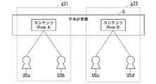
- FIG. 8 is a diagram showing a second example of the target of delay adjustment.
- two users a and b are Room A, and the content is used by the user systems 3-a and b and the computer systems 4-a and b.
- the two users c and d are Room B, and the contents are used by the user systems 3-c and d and the computer systems 4-c and d.
- the range g21 of the user systems 3-a and b, the computer systems 4-a and b and the central computer system 5 used by the group of users a and b of Room A is the first delay amount. It is an adjustment range.
- the range g22 of the user systems 3-c and d, the computer system 4-c, d and the central computer system 5 used by the group of users c and d of Room B is the adjustment range of the second delay amount. ..
- the delay adjusting device 6 and each delay control device adjust the delay amount in units of two or more user groups capable of interfering with each other in the same content. The method of adjusting the delay amount in such a case will be described later.
- FIG. 9 is a diagram showing a third example of the target of delay adjustment.
- the third example of FIG. 9 is an example in which one content is used by six users a to f, but can be divided into two or more user groups that can interfere with each other within the same content.
- the delay adjusting device 6 and each delay control device adjust the delay amount in units of two or more user groups in two or more user groups that can interfere with each other in the same content. The method of adjusting the delay amount in such a case will be described later.
- the delay difference can be set to zero among a plurality of users who use the content.
- a plurality of users having a delay difference exceeding the adjustment amount that can be adjusted by the delay control device are targeted.
- a situation may occur in which one or more users do not have a fair environment.
- An example of the adjustment method in such a case will be described in the following examples.
- First Example> only a group of users whose delay can be adjusted in advance is created, and measures are taken in advance.
- the delay amount information for each user is transmitted from the delay adjusting device 6 side to the central computer side on which the content operates.
- the central computer 53 selects a user who belongs to Room or a user group based on the received delay amount information.
- the second embodiment and the third embodiment are post-measures for constructing a pseudo-fair environment. If the first embodiment cannot be used, the following pseudo-fair environment may be constructed.
- the method of adjusting the delay amount in the case of FIG. 8 will be described with reference to FIGS. 10 to 13.
- the case where there are two users will be described as an example, but the number of users is not limited to this.
- the first embodiment is a case where one user participates in the content.
- FIG. 10 is a schematic configuration diagram of the information processing system in the first embodiment.
- the user a uses the user system 3-a and the computer system 4-a
- the user b uses the user system 3-b and the computer system 4-b.
- FIG. 11 is a diagram showing a delay amount in the case of no adjustment in the first embodiment.
- the horizontal axis is the user and the vertical axis is the delay amount (for example, (ms)).
- the delay amount Tfa between the user system 3-a and the computer system 4-a is 10 (ms)
- the delay amount Tba between the computer system 4-a and the central computer system 5 is 10 (ms).
- the delay amount Tfb between the user system 3-b and the computer system 4-b is 10 (ms)
- the delay amount Tbb between the computer system 4-b and the central computer system 5 is 40 (ms).
- FIG. 12 is a diagram showing an example when the maximum delay amount of the computer system is added in the first embodiment.
- Each axis of FIG. 12 is the same as that of FIG.
- the maximum delay amount that can be adjusted by each delay control device (33, 42, 44, 52) is 20 (ms). Therefore, for example, even if the second delay control device 44-a of the computer system 4-a adds the adjustment delay amount ATba by 20 (ms), the delay amount between the user a and the user b cannot be adjusted equally.
- FIG. 13 is a diagram showing an example of adjusting by End-to-End of the computer system in the first embodiment.
- Each axis of FIG. 13 is the same as that of FIG.
- the delay is not adjusted in each communication section, but is delayed so as to make the delay amount in the End-to-End (for example, between the user system and the central computer system) uniform. Adjust the amount.
- the delay adjusting device 6 and each delay control unit are controlled by this means so that the delay difference becomes as close as possible to zero.
- the second delay control device 44-a of the computer system 4-a adds 20 (ms) of the adjustment delay amount ATba, and the first delay control device 42-a of the computer system 4-a adjusts.
- the delay amount ATfa By adding the delay amount ATfa by 10 (ms), the total delay amount of the user a is made uniform to 40 (ms), which is equivalent to that of the user b.
- the adjustment delay amount ATba is made larger than the adjustment delay amount ATfa
- the adjustment delay amount ATfa may be larger than the adjustment delay amount ATba
- the adjustment delay amount ATba and the adjustment delay amount ATfa are It may be the same.
- FIG. 14 is a schematic configuration diagram of the information processing system in the second embodiment.
- the example of FIG. 14 for example, in Room A, users a and b of the user group g51 are using it, and in Room B, for example, users c and d of the user group g52 are using it.
- FIG. 15 is a diagram showing a delay amount in the case of no adjustment in the second embodiment.
- the horizontal axis is the user and the vertical axis is the delay amount (for example, (ms)).
- the delay amount Tfa between the user system 3-a and the computer system 4-a is 10 (ms)
- the delay amount Tba between the computer system 4-a and the central computer system 5 is 10 (ms).
- the delay amount Tfb between the user system 3-b and the computer system 4-b is 20 (ms)
- the delay amount Tbb between the computer system 4-b and the central computer system 5 is 40 (ms).
- the delay amount Tfc between the user system 3-c and the computer system 4-c is 20 (ms)
- the delay amount Tbc between the computer system 4-c and the central computer system 5 is 20 (ms).
- the delay amount Tfd between the user system 3-d and the computer system 4-d is 40 (ms)
- the delay amount Tbd between the computer system 4-d and the central computer system 5 is 10 (ms).
- FIG. 16 is a diagram showing an example when the maximum delay amount of the computer system is added in the second embodiment. Each axis of FIG. 16 is the same as that of FIG.
- the second delay control device 44-a of the computer system 4-a adds 20 (ms) of the adjustment delay amount ATba
- the first delay control device 42- of the computer system 4-a. a adds an adjustment delay amount ATfa by 20 (ms).
- the first delay control device 42-b of the computer system 4-b adds 20 (ms) of the adjustment delay amount ATfb.
- the second delay control device 44-c of the computer system 4-c adds 20 (ms) of the adjustment delay amount ATbc
- the first delay control device 42-c of the computer system 4-c adds the adjustment delay amount ATfc. 20 (ms) is added
- the second delay control device 44-d of the computer system 4-d adds 20 (ms) of the adjustment delay amount ATbd.
- FIG. 17 is a diagram showing an example when the delay amount is adjusted between the user groups in the second embodiment. Each axis of FIG. 17 is the same as that of FIG. In FIG. 17, the adjustment delay amount ATfa is 20 (ms), the adjustment delay amount ATba is 10 (ms), the adjustment delay amount ATbc is 10 (ms), and the adjustment delay amount ATbad is 10 (ms). be.
- the delay may be adjusted in consideration of the user group by adjusting so as to match the average delay between the user groups.
- the second embodiment may be adjusted in the same manner as in the first embodiment.
- FIG. 18 is a diagram showing a first application pattern.
- the first application pattern is the "local type", in which a computer on which content such as a game operates exists in the same base as the user.
- the delay amount is adjusted by adding the adjustment delay amount ATbn to the difference in the delay amount due to the first network NW1 between the computer and the central computer.
- FIG. 19 is a diagram showing a second application pattern.
- the second application pattern is "fog type", in which the computer on which the content such as a game operates is located at a different base from the user (for example, the computer is physically or logically placed near the user from the central computer). Exists in.
- the configuration example of FIG. 1 is the second application pattern. In this case, there is a second network NW2 between the input / output device and the computer, and there is a first network NW1 between the computer and the central computer, and a delay amount is generated in each of them.
- the adjustment delay amount ATbn for the difference in the delay amount due to the first network NW1 between the computer and the central computer is added, and the second network NW2 between the computer and the input / output device is added.
- the delay amount is adjusted by adding the adjustment delay amount ATfn to the difference in the delay amount due to the above.
- FIG. 20 is a diagram showing a third application pattern.
- the third application pattern is a "cloud type", in which a computer on which content such as a game operates exists on the cloud, and a central computer also exists in the cloud.
- the delay amount is adjusted by adding the adjustment delay amount Atfn to the delay amount by the second network NW2 between the computer and the input / output device.
- the application patterns shown in FIGS. 18 to 20 are examples, and the classification is for convenience only, and some cloud gaming is close to the form of fog gaming. Further, depending on the configuration of the information processing system 1, the delay amount may be adjusted by combining the first to third application patterns described above.
- ⁇ Modification example> a modified example will be described.
- the relationship between the central computer and the computer may be applied to the relationship between the central computer (upper level) and the central computer (lower level).
- the delay amount is adjusted between the delay amount Tfn between the input / output device and the computer, the delay amount Tb1n between the computer and the central computer, and between the central computer (upper) and the central computer (lower).
- the delay amount Tb2n may be three.
- a delay control device may be provided between the central computer (upper level) and the central computer (lower level).
- the delay amount is measured and the delay picture is adjusted between the central computer and the computer, and between the computer and the input / output device.
- the amount of delay between a plurality of users having different communication environments can be kept constant.
- the delay amount among the participants can be made uniform in the highly competitive event, so that fairness can be maintained.
- the present invention can be applied to, for example, a gaming system, an eSports system, a remote desktop system, a computer rental system, and the like.
Landscapes
- Engineering & Computer Science (AREA)
- Environmental & Geological Engineering (AREA)
- Computer Networks & Wireless Communication (AREA)
- Signal Processing (AREA)
- Data Exchanges In Wide-Area Networks (AREA)
Priority Applications (3)
| Application Number | Priority Date | Filing Date | Title |
|---|---|---|---|
| US18/027,597 US12549463B2 (en) | 2020-09-29 | 2020-09-29 | Information processing system, information processing method and program |
| PCT/JP2020/036859 WO2022070247A1 (ja) | 2020-09-29 | 2020-09-29 | 情報処理システム、情報処理方法およびプログラム |
| JP2022553253A JP7620232B2 (ja) | 2020-09-29 | 2020-09-29 | 情報処理システム、情報処理方法およびプログラム |
Applications Claiming Priority (1)
| Application Number | Priority Date | Filing Date | Title |
|---|---|---|---|
| PCT/JP2020/036859 WO2022070247A1 (ja) | 2020-09-29 | 2020-09-29 | 情報処理システム、情報処理方法およびプログラム |
Publications (1)
| Publication Number | Publication Date |
|---|---|
| WO2022070247A1 true WO2022070247A1 (ja) | 2022-04-07 |
Family
ID=80951516
Family Applications (1)
| Application Number | Title | Priority Date | Filing Date |
|---|---|---|---|
| PCT/JP2020/036859 Ceased WO2022070247A1 (ja) | 2020-09-29 | 2020-09-29 | 情報処理システム、情報処理方法およびプログラム |
Country Status (3)
| Country | Link |
|---|---|
| US (1) | US12549463B2 (https=) |
| JP (1) | JP7620232B2 (https=) |
| WO (1) | WO2022070247A1 (https=) |
Cited By (1)
| Publication number | Priority date | Publication date | Assignee | Title |
|---|---|---|---|---|
| WO2026069478A1 (ja) * | 2024-09-25 | 2026-04-02 | Ntt株式会社 | 無瞬断切替システムおよび遅延調整方法 |
Citations (4)
| Publication number | Priority date | Publication date | Assignee | Title |
|---|---|---|---|---|
| JP2003062350A (ja) * | 2001-08-30 | 2003-03-04 | Sony Corp | ネットワークゲームシステム、ネットワークゲームサーバ装置、及びネットワークゲーム端末装置 |
| JP2005064970A (ja) * | 2003-08-15 | 2005-03-10 | Nippon Telegr & Teleph Corp <Ntt> | 配信レート制御方法及びシステム |
| JP2012199728A (ja) * | 2011-03-22 | 2012-10-18 | Hitachi Ltd | ネットワークシステム、及び通信装置 |
| JP2015065527A (ja) * | 2013-09-24 | 2015-04-09 | 株式会社日立製作所 | 通信システム及び通信装置 |
Family Cites Families (44)
| Publication number | Priority date | Publication date | Assignee | Title |
|---|---|---|---|---|
| JPH10117215A (ja) | 1996-08-22 | 1998-05-06 | Furukawa Electric Co Ltd:The | ネットワーク間接続方法及びその装置 |
| DE19945663A1 (de) | 1999-09-23 | 2001-04-05 | Siemens Ag | Internet-Telefonadapter |
| US6678524B1 (en) | 2000-05-31 | 2004-01-13 | Telefonaktiebolaget Lm Ericsson (Publ) | Bearer selection in a mobile communication system having both circuit-switched and packet-switched bearers |
| JP4095325B2 (ja) | 2002-03-29 | 2008-06-04 | キヤノン株式会社 | 画像配信方法およびその動作処理を実行するプログラムおよびそのプログラムを記憶した記憶媒体、および画像配信装置および画像受信装置 |
| JP4458767B2 (ja) | 2003-04-16 | 2010-04-28 | エボリウム・エス・アー・エス | 携帯電話システム |
| US7246172B2 (en) | 2003-06-06 | 2007-07-17 | Matsushita Electric Industrial Co., Ltd. | Static dense multicast path and bandwidth management |
| KR20060088939A (ko) | 2005-02-02 | 2006-08-07 | 삼성전자주식회사 | 광 네트워크에서의 광채널 할당시스템 및 그 방법 |
| US20070079307A1 (en) | 2005-09-30 | 2007-04-05 | Puneet Dhawan | Virtual machine based network carriers |
| US7822065B2 (en) | 2007-01-07 | 2010-10-26 | Wei Lu | Open wireless architecture (OWA) medium access control (MAC) processing architecture for future mobile terminal |
| US20080235361A1 (en) | 2007-03-21 | 2008-09-25 | David Crosbie | Management layer method and apparatus for dynamic assignment of users to computer resources |
| JP5164628B2 (ja) | 2008-03-24 | 2013-03-21 | 株式会社日立製作所 | ネットワークスイッチ装置、サーバシステム及びサーバシステムにおけるサーバ移送方法 |
| TW201007574A (en) | 2008-08-13 | 2010-02-16 | Inventec Corp | Internet server system and method of constructing and starting a virtual machine |
| EP2175607A1 (en) | 2008-10-08 | 2010-04-14 | NEC Corporation | Method for establishing a thin client session |
| US20110126197A1 (en) | 2009-11-25 | 2011-05-26 | Novell, Inc. | System and method for controlling cloud and virtualized data centers in an intelligent workload management system |
| US9141420B2 (en) | 2010-11-04 | 2015-09-22 | Alcatel Lucent | Overload control in a cloud computing environment |
| US9785478B1 (en) | 2010-11-12 | 2017-10-10 | Vmware, Inc. | Mass migration of desktop deployments to virtual desktop infrastructures |
| WO2013003327A1 (en) | 2011-06-27 | 2013-01-03 | University Of Massachusetts | Dynamic advance reservation with delayed allocation |
| US9461881B2 (en) | 2011-09-30 | 2016-10-04 | Commvault Systems, Inc. | Migration of existing computing systems to cloud computing sites or virtual machines |
| US8719534B1 (en) | 2012-03-21 | 2014-05-06 | Netapp, Inc. | Method and system for generating a migration plan |
| KR101384934B1 (ko) | 2012-06-29 | 2014-04-14 | 인텔렉추얼디스커버리 주식회사 | 모바일 노드의 이동을 처리하기 위한 방법 및 장치 |
| EP2687982A1 (en) | 2012-07-16 | 2014-01-22 | NTT DoCoMo, Inc. | Hierarchical system for managing a plurality of virtual machines, method and computer program |
| US20140181984A1 (en) | 2012-12-21 | 2014-06-26 | International Business Machines Corporation | Method and apparatus for authentication of solution topology |
| US9069608B2 (en) | 2013-03-06 | 2015-06-30 | Vmware, Inc. | Method and system for providing a roaming remote desktop |
| EP3041311B1 (en) | 2013-08-26 | 2023-10-04 | Nec Corporation | Communication apparatus and method in communication system, and communication path control apparatus and method |
| US20150363219A1 (en) | 2014-03-14 | 2015-12-17 | Avni Networks Inc. | Optimization to create a highly scalable virtual netork service/application using commodity hardware |
| US9146769B1 (en) | 2015-04-02 | 2015-09-29 | Shiva Shankar | Systems and methods for copying a source machine to a target virtual machine |
| US20170235737A1 (en) | 2016-02-12 | 2017-08-17 | Nutanix, Inc. | Entity database ranking |
| US10749756B2 (en) * | 2016-06-24 | 2020-08-18 | Advanced Micro Devices, Inc. | Channel training using a replica lane |
| US10785144B2 (en) | 2016-12-30 | 2020-09-22 | Equinix, Inc. | Latency equalization |
| US11089105B1 (en) | 2017-12-14 | 2021-08-10 | Pure Storage, Inc. | Synchronously replicating datasets in cloud-based storage systems |
| US10929195B2 (en) | 2017-08-07 | 2021-02-23 | Dynavisor, Inc. | Method and system for cloud virtualization |
| US10855537B2 (en) | 2018-04-24 | 2020-12-01 | Vmware, Inc. | Methods and apparatus for template driven infrastructure in virtualized server systems |
| EP3564687B1 (en) | 2018-05-03 | 2023-02-22 | Siemens Aktiengesellschaft | Determination of power transmission line parameters using asynchronous measurements |
| US11044185B2 (en) * | 2018-12-14 | 2021-06-22 | At&T Intellectual Property I, L.P. | Latency prediction and guidance in wireless communication systems |
| CN111416794B (zh) | 2019-01-08 | 2022-07-29 | 华为技术有限公司 | 一种数据传输方法及电子设备 |
| US11301407B2 (en) | 2019-01-08 | 2022-04-12 | Intel Corporation | Technologies for accelerator fabric protocol multipathing |
| CN113615136A (zh) * | 2019-03-11 | 2021-11-05 | 思杰系统有限公司 | 面向用户体验的路径选择 |
| US11496404B2 (en) | 2019-06-27 | 2022-11-08 | Google Llc | Congestion control for low latency datacenter networks |
| EP3997844A1 (en) * | 2019-07-10 | 2022-05-18 | Telefonaktiebolaget LM Ericsson (publ) | Technique for determining a packet delay budget |
| US20210158260A1 (en) * | 2019-11-25 | 2021-05-27 | Cisco Technology, Inc. | INTERPRETABLE PEER GROUPING FOR COMPARING KPIs ACROSS NETWORK ENTITIES |
| CN117395167A (zh) * | 2020-01-21 | 2024-01-12 | 华为技术有限公司 | 服务等级配置方法以及装置 |
| US11784906B2 (en) * | 2020-02-04 | 2023-10-10 | Nvidia Corporation | System-latency-aware display device |
| US11344803B1 (en) * | 2020-06-02 | 2022-05-31 | Amazon Technologies, Inc. | Techniques for determining network latency |
| US11929903B2 (en) * | 2020-12-29 | 2024-03-12 | VMware LLC | Emulating packet flows to assess network links for SD-WAN |
-
2020
- 2020-09-29 WO PCT/JP2020/036859 patent/WO2022070247A1/ja not_active Ceased
- 2020-09-29 JP JP2022553253A patent/JP7620232B2/ja active Active
- 2020-09-29 US US18/027,597 patent/US12549463B2/en active Active
Patent Citations (4)
| Publication number | Priority date | Publication date | Assignee | Title |
|---|---|---|---|---|
| JP2003062350A (ja) * | 2001-08-30 | 2003-03-04 | Sony Corp | ネットワークゲームシステム、ネットワークゲームサーバ装置、及びネットワークゲーム端末装置 |
| JP2005064970A (ja) * | 2003-08-15 | 2005-03-10 | Nippon Telegr & Teleph Corp <Ntt> | 配信レート制御方法及びシステム |
| JP2012199728A (ja) * | 2011-03-22 | 2012-10-18 | Hitachi Ltd | ネットワークシステム、及び通信装置 |
| JP2015065527A (ja) * | 2013-09-24 | 2015-04-09 | 株式会社日立製作所 | 通信システム及び通信装置 |
Cited By (1)
| Publication number | Priority date | Publication date | Assignee | Title |
|---|---|---|---|---|
| WO2026069478A1 (ja) * | 2024-09-25 | 2026-04-02 | Ntt株式会社 | 無瞬断切替システムおよび遅延調整方法 |
Also Published As
| Publication number | Publication date |
|---|---|
| US12549463B2 (en) | 2026-02-10 |
| US20230403220A1 (en) | 2023-12-14 |
| JPWO2022070247A1 (https=) | 2022-04-07 |
| JP7620232B2 (ja) | 2025-01-23 |
Similar Documents
| Publication | Publication Date | Title |
|---|---|---|
| US8155157B2 (en) | Method and apparatus for synchronizing applications of terminals in communication network | |
| US20230405454A1 (en) | Multisession remote game rendering | |
| EP3591502B1 (en) | Virtual reality image sending method and apparatus | |
| US8625443B2 (en) | System for measuring transmission bandwidth for media streaming and method for same | |
| US12021758B2 (en) | Managing network slice bandwidth for remote game sessions | |
| CN111587137A (zh) | 检测和补偿游戏系统中的显示滞后 | |
| EP3005813A1 (en) | Buffer-aware radio resource management | |
| US10932140B2 (en) | Link restoration method and apparatus, and device | |
| JP2018505576A (ja) | 複数のシンクデバイスへのワイヤレスストリーミング伝送のタイミングを同期する技法 | |
| CN106550248B (zh) | 一种音视频同步的方法和设备 | |
| JP7620232B2 (ja) | 情報処理システム、情報処理方法およびプログラム | |
| CN109348264A (zh) | 视频资源共享方法、装置、存储介质及电子设备 | |
| Zhu et al. | Mobile edge resource optimization for multiplayer interactive virtual reality game | |
| Xu et al. | Anti-jamming transmission in UAV communication networks: A Stackelberg game approach | |
| US20160323177A1 (en) | Heterogeneous network system, network apparatus, and rendezvous path selection method thereof | |
| JP6195757B2 (ja) | コンテンツ配信サーバおよびコンテンツ配信プログラム | |
| US12192072B2 (en) | Virtual reality content streaming based on quality of experience level | |
| CN112134598A (zh) | 一种指示方法、终端及网络侧设备 | |
| Huang et al. | Simultaneous output-timing control in networked games and virtual environments | |
| US12323598B2 (en) | Metering bits in video encoder to achieve targeted data rate and video quality level | |
| WO2020037483A1 (zh) | 控制功能的设置方法、控制设备和控制系统 | |
| JP6430223B2 (ja) | 通信装置、遠隔制御方法、コンピュータプログラム及び遠隔制御システム | |
| WO2024070530A1 (ja) | 端末装置、通信方法およびプログラム | |
| Ali | Performance Dynamics of Directional Extended Reality Networks | |
| CN120957055A (zh) | 无线耳机设备、通信切换方法及装置 |
Legal Events
| Date | Code | Title | Description |
|---|---|---|---|
| ENP | Entry into the national phase |
Ref document number: 2022553253 Country of ref document: JP Kind code of ref document: A |
|
| NENP | Non-entry into the national phase |
Ref country code: DE |
|
| 122 | Ep: pct application non-entry in european phase |
Ref document number: 20956177 Country of ref document: EP Kind code of ref document: A1 |
|
| WWG | Wipo information: grant in national office |
Ref document number: 18027597 Country of ref document: US |