WO2022065340A1 - 蓄熱材、およびその製造方法 - Google Patents
蓄熱材、およびその製造方法 Download PDFInfo
- Publication number
- WO2022065340A1 WO2022065340A1 PCT/JP2021/034708 JP2021034708W WO2022065340A1 WO 2022065340 A1 WO2022065340 A1 WO 2022065340A1 JP 2021034708 W JP2021034708 W JP 2021034708W WO 2022065340 A1 WO2022065340 A1 WO 2022065340A1
- Authority
- WO
- WIPO (PCT)
- Prior art keywords
- heat storage
- storage material
- heat
- metal layer
- film
- Prior art date
- Legal status (The legal status is an assumption and is not a legal conclusion. Google has not performed a legal analysis and makes no representation as to the accuracy of the status listed.)
- Ceased
Links
Images


Classifications
-
- F—MECHANICAL ENGINEERING; LIGHTING; HEATING; WEAPONS; BLASTING
- F24—HEATING; RANGES; VENTILATING
- F24S—SOLAR HEAT COLLECTORS; SOLAR HEAT SYSTEMS
- F24S70/00—Details of absorbing elements
- F24S70/20—Details of absorbing elements characterised by absorbing coatings; characterised by surface treatment for increasing absorption
-
- B—PERFORMING OPERATIONS; TRANSPORTING
- B32—LAYERED PRODUCTS
- B32B—LAYERED PRODUCTS, i.e. PRODUCTS BUILT-UP OF STRATA OF FLAT OR NON-FLAT, e.g. CELLULAR OR HONEYCOMB, FORM
- B32B27/00—Layered products comprising a layer of synthetic resin
- B32B27/36—Layered products comprising a layer of synthetic resin comprising polyesters
-
- B—PERFORMING OPERATIONS; TRANSPORTING
- B64—AIRCRAFT; AVIATION; COSMONAUTICS
- B64G—COSMONAUTICS; VEHICLES OR EQUIPMENT THEREFOR
- B64G1/00—Cosmonautic vehicles
- B64G1/22—Parts of, or equipment specially adapted for fitting in or to, cosmonautic vehicles
-
- B—PERFORMING OPERATIONS; TRANSPORTING
- B64—AIRCRAFT; AVIATION; COSMONAUTICS
- B64G—COSMONAUTICS; VEHICLES OR EQUIPMENT THEREFOR
- B64G1/00—Cosmonautic vehicles
- B64G1/22—Parts of, or equipment specially adapted for fitting in or to, cosmonautic vehicles
- B64G1/46—Arrangements or adaptations of devices for control of environment or living conditions
- B64G1/50—Arrangements or adaptations of devices for control of environment or living conditions for temperature control
-
- F—MECHANICAL ENGINEERING; LIGHTING; HEATING; WEAPONS; BLASTING
- F24—HEATING; RANGES; VENTILATING
- F24S—SOLAR HEAT COLLECTORS; SOLAR HEAT SYSTEMS
- F24S20/00—Solar heat collectors specially adapted for particular uses or environments
- F24S20/20—Solar heat collectors for receiving concentrated solar energy, e.g. receivers for solar power plants
-
- F—MECHANICAL ENGINEERING; LIGHTING; HEATING; WEAPONS; BLASTING
- F24—HEATING; RANGES; VENTILATING
- F24S—SOLAR HEAT COLLECTORS; SOLAR HEAT SYSTEMS
- F24S60/00—Arrangements for storing heat collected by solar heat collectors
- F24S60/10—Arrangements for storing heat collected by solar heat collectors using latent heat
-
- F—MECHANICAL ENGINEERING; LIGHTING; HEATING; WEAPONS; BLASTING
- F24—HEATING; RANGES; VENTILATING
- F24S—SOLAR HEAT COLLECTORS; SOLAR HEAT SYSTEMS
- F24S60/00—Arrangements for storing heat collected by solar heat collectors
- F24S60/30—Arrangements for storing heat collected by solar heat collectors storing heat in liquids
-
- F—MECHANICAL ENGINEERING; LIGHTING; HEATING; WEAPONS; BLASTING
- F24—HEATING; RANGES; VENTILATING
- F24S—SOLAR HEAT COLLECTORS; SOLAR HEAT SYSTEMS
- F24S70/00—Details of absorbing elements
- F24S70/10—Details of absorbing elements characterised by the absorbing material
- F24S70/12—Details of absorbing elements characterised by the absorbing material made of metallic material
-
- F—MECHANICAL ENGINEERING; LIGHTING; HEATING; WEAPONS; BLASTING
- F24—HEATING; RANGES; VENTILATING
- F24S—SOLAR HEAT COLLECTORS; SOLAR HEAT SYSTEMS
- F24S70/00—Details of absorbing elements
- F24S70/20—Details of absorbing elements characterised by absorbing coatings; characterised by surface treatment for increasing absorption
- F24S70/25—Coatings made of metallic material
-
- F—MECHANICAL ENGINEERING; LIGHTING; HEATING; WEAPONS; BLASTING
- F24—HEATING; RANGES; VENTILATING
- F24S—SOLAR HEAT COLLECTORS; SOLAR HEAT SYSTEMS
- F24S70/00—Details of absorbing elements
- F24S70/30—Auxiliary coatings, e.g. anti-reflective coatings
-
- F—MECHANICAL ENGINEERING; LIGHTING; HEATING; WEAPONS; BLASTING
- F28—HEAT EXCHANGE IN GENERAL
- F28D—HEAT-EXCHANGE APPARATUS, NOT PROVIDED FOR IN ANOTHER SUBCLASS, IN WHICH THE HEAT-EXCHANGE MEDIA DO NOT COME INTO DIRECT CONTACT
- F28D20/00—Heat storage plants or apparatus in general; Regenerative heat-exchange apparatus not covered by groups F28D17/00 or F28D19/00
-
- F—MECHANICAL ENGINEERING; LIGHTING; HEATING; WEAPONS; BLASTING
- F28—HEAT EXCHANGE IN GENERAL
- F28F—DETAILS OF HEAT-EXCHANGE AND HEAT-TRANSFER APPARATUS, OF GENERAL APPLICATION
- F28F13/00—Arrangements for modifying heat-transfer, e.g. increasing, decreasing
- F28F13/18—Arrangements for modifying heat-transfer, e.g. increasing, decreasing by applying coatings, e.g. radiation-absorbing, radiation-reflecting; by surface treatment, e.g. polishing
-
- F—MECHANICAL ENGINEERING; LIGHTING; HEATING; WEAPONS; BLASTING
- F28—HEAT EXCHANGE IN GENERAL
- F28F—DETAILS OF HEAT-EXCHANGE AND HEAT-TRANSFER APPARATUS, OF GENERAL APPLICATION
- F28F21/00—Constructions of heat-exchange apparatus characterised by the selection of particular materials
- F28F21/08—Constructions of heat-exchange apparatus characterised by the selection of particular materials of metal
-
- H—ELECTRICITY
- H02—GENERATION; CONVERSION OR DISTRIBUTION OF ELECTRIC POWER
- H02S—GENERATION OF ELECTRIC POWER BY CONVERSION OF INFRARED RADIATION, VISIBLE LIGHT OR ULTRAVIOLET LIGHT, e.g. USING PHOTOVOLTAIC [PV] MODULES
- H02S40/00—Components or accessories in combination with PV modules, not provided for in groups H02S10/00 - H02S30/00
- H02S40/40—Thermal components
- H02S40/44—Means to utilise heat energy, e.g. hybrid systems producing warm water and electricity at the same time
-
- H—ELECTRICITY
- H10—SEMICONDUCTOR DEVICES; ELECTRIC SOLID-STATE DEVICES NOT OTHERWISE PROVIDED FOR
- H10F—INORGANIC SEMICONDUCTOR DEVICES SENSITIVE TO INFRARED RADIATION, LIGHT, ELECTROMAGNETIC RADIATION OF SHORTER WAVELENGTH OR CORPUSCULAR RADIATION
- H10F77/00—Constructional details of devices covered by this subclass
- H10F77/60—Arrangements for cooling, heating, ventilating or compensating for temperature fluctuations
- H10F77/63—Arrangements for cooling directly associated or integrated with photovoltaic cells, e.g. heat sinks directly associated with the photovoltaic cells or integrated Peltier elements for active cooling
- H10F77/67—Arrangements for cooling directly associated or integrated with photovoltaic cells, e.g. heat sinks directly associated with the photovoltaic cells or integrated Peltier elements for active cooling including means to utilise heat energy directly associated with the photovoltaic cells, e.g. integrated Seebeck elements
-
- B—PERFORMING OPERATIONS; TRANSPORTING
- B64—AIRCRAFT; AVIATION; COSMONAUTICS
- B64G—COSMONAUTICS; VEHICLES OR EQUIPMENT THEREFOR
- B64G1/00—Cosmonautic vehicles
- B64G1/10—Artificial satellites; Systems of such satellites; Interplanetary vehicles
-
- F—MECHANICAL ENGINEERING; LIGHTING; HEATING; WEAPONS; BLASTING
- F24—HEATING; RANGES; VENTILATING
- F24S—SOLAR HEAT COLLECTORS; SOLAR HEAT SYSTEMS
- F24S60/00—Arrangements for storing heat collected by solar heat collectors
-
- Y—GENERAL TAGGING OF NEW TECHNOLOGICAL DEVELOPMENTS; GENERAL TAGGING OF CROSS-SECTIONAL TECHNOLOGIES SPANNING OVER SEVERAL SECTIONS OF THE IPC; TECHNICAL SUBJECTS COVERED BY FORMER USPC CROSS-REFERENCE ART COLLECTIONS [XRACs] AND DIGESTS
- Y02—TECHNOLOGIES OR APPLICATIONS FOR MITIGATION OR ADAPTATION AGAINST CLIMATE CHANGE
- Y02B—CLIMATE CHANGE MITIGATION TECHNOLOGIES RELATED TO BUILDINGS, e.g. HOUSING, HOUSE APPLIANCES OR RELATED END-USER APPLICATIONS
- Y02B10/00—Integration of renewable energy sources in buildings
- Y02B10/20—Solar thermal
-
- Y—GENERAL TAGGING OF NEW TECHNOLOGICAL DEVELOPMENTS; GENERAL TAGGING OF CROSS-SECTIONAL TECHNOLOGIES SPANNING OVER SEVERAL SECTIONS OF THE IPC; TECHNICAL SUBJECTS COVERED BY FORMER USPC CROSS-REFERENCE ART COLLECTIONS [XRACs] AND DIGESTS
- Y02—TECHNOLOGIES OR APPLICATIONS FOR MITIGATION OR ADAPTATION AGAINST CLIMATE CHANGE
- Y02E—REDUCTION OF GREENHOUSE GAS [GHG] EMISSIONS, RELATED TO ENERGY GENERATION, TRANSMISSION OR DISTRIBUTION
- Y02E10/00—Energy generation through renewable energy sources
- Y02E10/40—Solar thermal energy, e.g. solar towers
-
- Y—GENERAL TAGGING OF NEW TECHNOLOGICAL DEVELOPMENTS; GENERAL TAGGING OF CROSS-SECTIONAL TECHNOLOGIES SPANNING OVER SEVERAL SECTIONS OF THE IPC; TECHNICAL SUBJECTS COVERED BY FORMER USPC CROSS-REFERENCE ART COLLECTIONS [XRACs] AND DIGESTS
- Y02—TECHNOLOGIES OR APPLICATIONS FOR MITIGATION OR ADAPTATION AGAINST CLIMATE CHANGE
- Y02E—REDUCTION OF GREENHOUSE GAS [GHG] EMISSIONS, RELATED TO ENERGY GENERATION, TRANSMISSION OR DISTRIBUTION
- Y02E60/00—Enabling technologies; Technologies with a potential or indirect contribution to GHG emissions mitigation
- Y02E60/14—Thermal energy storage
-
- Y—GENERAL TAGGING OF NEW TECHNOLOGICAL DEVELOPMENTS; GENERAL TAGGING OF CROSS-SECTIONAL TECHNOLOGIES SPANNING OVER SEVERAL SECTIONS OF THE IPC; TECHNICAL SUBJECTS COVERED BY FORMER USPC CROSS-REFERENCE ART COLLECTIONS [XRACs] AND DIGESTS
- Y02—TECHNOLOGIES OR APPLICATIONS FOR MITIGATION OR ADAPTATION AGAINST CLIMATE CHANGE
- Y02E—REDUCTION OF GREENHOUSE GAS [GHG] EMISSIONS, RELATED TO ENERGY GENERATION, TRANSMISSION OR DISTRIBUTION
- Y02E70/00—Other energy conversion or management systems reducing GHG emissions
- Y02E70/30—Systems combining energy storage with energy generation of non-fossil origin
Definitions
- the present invention relates to a heat storage material and a method for producing the same.
- Non-Patent Document 1 has a problem that it emits a large amount of radiation even in the far infrared region and does not show excellent heat storage. Further, the invention described in Patent Document 1 is based on injection molding of a resin using a mold, and it is not possible to mold a metal film having a highly versatile form, and it is difficult to apply it to various products. There is also a problem in practicality.
- the present invention has been made in view of the above problems, and normally absorbs incompatible visible light and near infrared rays (that is, has low reflectance), and emits far infrared rays with small amount (that is, high reflectance). It is an object of the present invention to provide a heat storage material having characteristics and a method for producing the same.
- the heat storage material according to the present invention is characterized in that the surface of the heat storage member is provided with a metal layer containing a concavo-convex shape, and the height of the concavo-convex shape is 100 nm or more and 1000 nm or less.
- the method for producing a heat storage material according to the present invention includes a first step of forming an uneven shape of a metal oxide, a second step of forming a metal layer on the uneven shape of the metal oxide, and the metal of the metal layer. It is characterized by including a third step of adhering a heat storage member to a surface opposite to the uneven shape of the oxide.
- the present invention by using a metal layer having an uneven shape, it is possible to provide a heat storage material having absorption and heat storage characteristics that are normally incompatible with each other.
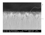
- FIG. It is a measurement result of the reflectance spectrum in the infrared region of the heat storage material obtained in Example 1 and Example 3 and the heat storage material obtained in Comparative Example 1. It is an electron microscope observation figure of the cross section of the heat storage material obtained in Example 3.
- FIG. It is a schematic diagram which shows the embodiment of the article of this invention. It is a schematic diagram which shows the embodiment of the article of this invention. It is a schematic diagram which shows the embodiment of the article of this invention. It is a schematic diagram which shows the embodiment of the article of this invention.
- one embodiment of the heat storage material for example, a heat storage device or clothing
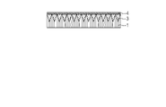
- the heat storage material includes a metal layer 1 containing a fine uneven shape on the surface of the heat storage member 5, and has a fine uneven shape.
- the height is 100 nm or more and 1000 nm or less.
- a fine concavo-convex shape may be simply referred to as a concavo-convex shape or a fine concavo-convex shape.
- the heat storage member 5 is an element that temporarily stores the heat obtained by the metal layer 1, and is included in the heat storage member 5.
- the heat storage material is not particularly limited as long as it has a large heat capacity, and may be a material containing any one of water, paraffin, oil, fiber, sand, salt, metal, alloy, and metal oxide.
- As an alloy of heat storage material Al—Si alloy is particularly desirable because it has excellent heat storage.
- Magnesium oxide, calcium oxide, or lithium silicate is desirable as the metal oxide of the heat storage material because it has excellent heat storage.
- Aluminum is particularly desirable as a metal for heat storage because it has excellent heat storage.
- a mixed molten salt of sodium nitrate-potassium nitrate-sodium nitrite, a hydroxide-based mixed molten salt, an alkaline carbonate, or an alkaline halide molten salt is particularly desirable because it has excellent heat storage.
- the heat storage member 5 may have a base material (not shown) provided between the metal layer 1 and the heat storage material, and the shape of the base material (not shown) may be a shape according to the purpose of use. Any material can be used, and examples thereof include a flat plate shape, a film shape, and a sheet shape, but the shape is not limited thereto.
- the material of the base material (not shown) include, but are not limited to, metal, glass, ceramics, wood, paper, and resin.
- the resin include polyester, triacetyl cellulose, cellulose acetate, polyethylene terephthalate, polypropylene, polystyrene, and polycarbonate.
- thermoplastic resins such as polymethylmethacrylate, ABS resin, polyphenylene oxide, polyurethane, polyethylene and polyvinyl chloride.
- thermosetting resins such as unsaturated polyester resin, phenol resin, crosslinked polyurethane, crosslinked acrylic resin, and crosslinked saturated polyester resin can be mentioned.
- the metal layer 1 and the heat storage member 5 may be bonded by an adhesive layer 6.
- the adhesive layer 6 may be any layer as long as the metal layer 1 and the heat storage member 5 can be adhered to each other, and examples thereof include a layer made of a cured product of an adhesive resin (for example, an epoxy resin) and double-sided tape.
- FIGS. 2A and 2B show a member (a member shown in FIG. 1C described later) having a transparent metal oxide fine uneven shape 3 and a metal oxide layer 4 on the surface of the metal layer 1.
- the member may include the film shown in FIGS. 1A or 1B described later.
- Highly conductive metals such as aluminum and nickel emit little far infrared rays and have heat storage properties, but do not show absorbance.
- the fine uneven shape due to the sub-wavelength structure smaller than the wavelength of visible light has an antireflection effect, and by continuously changing the space occupancy of the structural part, excellent wavelength band characteristics can be obtained. It is known to exhibit incident angle characteristics. Therefore, when the metal surface is made finely uneven, the reflection on the metal surface is suppressed in a wide wavelength region of visible light, the reflectance in the entire visible light region is lowered, the surface looks black, and the absorbance is exhibited.
- Non-Patent Document 1 has a fine uneven shape obtained by oxidizing the nickel surface on the surface, it emits a large amount of radiation (low reflectance) even in the far infrared region and does not exhibit heat storage.
- the present inventors have found that, in addition to the heat storage property of the metal itself, the specific shape of the fine uneven shape of the metal surface is important for exhibiting the absorbance and the heat storage property, and the present invention has been made.
- the fine uneven shape may be referred to as a fine uneven shape or simply an uneven shape).
- the heat storage material of the present embodiment is provided with a specific fine uneven shape provided on the metal layer on the surface, it is possible to exhibit both absorbance and heat storage.
- the metal layer containing the fine uneven shape of the heat storage material of the present embodiment has a reflectance of 10% or less in the visible light region (550 nm) and a reflectance of 70% or more in the far infrared light region (10 ⁇ m). Is preferable.
- the film formed on the surface of the heat storage member of the heat storage material of the present embodiment has excellent heat storage property, and the heat storage material of the heat storage member in contact with the metal layer having excellent heat storage property can efficiently store heat. ..
- one embodiment of the metal layer 1 is a film provided with the metal layer 1 having a fine uneven shape 2 on the surface.
- a metal having high conductivity is preferable.
- the metal having high conductivity include silver, copper, gold, aluminum, magnesium, tungsten, cobalt, zinc, nickel, chromium and the like, nickel, zinc and chromium are preferable, and nickel is particularly preferable.
- the fine concavo-convex shape 2 provided on the surface of the metal layer 1 is also preferably made of the metal having high conductivity, and more preferably made of the same metal as the metal layer 1.
- the metal layer 1 is preferably a plated layer formed by plating.
- the fine uneven shape object 2 is a fine uneven shape object provided on one surface of the metal layer 1, and the height of the fine uneven shape object 2 is the apex and the concave portion of the convex portion formed on the surface of the metal layer. Refers to the height difference from the bottom point.
- the average height of the fine uneven shape object 2 is 100 nm or more and 1000 nm or less, preferably 100 nm or more and 500 nm or less.
- the height of the fine uneven shape object 2 means the height difference between the peak and the valley bottom defined in "Definition and display of surface roughness" of JIS-B-061, and the maximum roughness (Rmax). Is equivalent to.
- the film having the metal layer 1 of the present embodiment preferably has an average surface roughness Ra'of 1 nm or more and 50 nm or less, which is a surface extension of the center line average roughness Ra.
- the average surface roughness Ra'value (nm) is a three-dimensional extension of the center line average roughness Ra defined in JIS B 0601 applied to the measurement surface, and is "specified from the reference surface". It is expressed as "the average value of the absolute values of the deviations to the surface” and is obtained by the following equation (1).
- Ra' is the average surface roughness (nm)
- S 0 is the area when the measurement surface is ideally flat
- F (X, Y) is the height at the measurement point (X, Y) where the X coordinate is X and the Y coordinate is Y.
- XL to X R are the range of the X coordinate of the measurement surface
- Y B to Y T are the range of the Y coordinate of the measurement surface
- Z 0 is the average height in the measurement surface.
- the film having the metal layer 1 of the present embodiment preferably has a specific surface area Sr of 1.0 or more and 3.0 or less on the surface thereof.
- Equation (2) S 0 is the surface area when the measurement surface is ideally flat, and S is the surface area of the actual measurement surface.
- the surface area of the actual measurement surface is divided into small triangles ⁇ ABC consisting of three data points (A, B, C) closest to each other, and then the area ⁇ S of each small triangle is calculated by the following equation (3).
- the surface area S is obtained by using the vector product, and the sum of the ⁇ S is obtained.
- [ ⁇ S ( ⁇ ABC)] 2 [s (s-AB) (s-BC) (s-CA)] Equation (3)
- the height of the fine uneven shape object 2 can be determined by observing the cross section of the metal layer 1 with a scanning electron microscope or the like. Further, the average surface roughness Ra'and the specific surface area of the surface of the film provided with the metal layer of the heat storage material of the present invention can be determined by observing the surface of the film provided with the metal layer using a scanning probe microscope or the like. Can be done.
- the film provided with the metal layer may have deposits present on the surface of the fine uneven shape object 2 (for example, a metal oxide described later), and the average surface roughness Ra'and the specific surface area of the surface provided with the metal layer of the heat storage material.
- the surface area is a value including deposits.
- a membrane provided with a metal layer may be referred to as an absorption heat storage membrane.
- the fine uneven shape of the transparent metal oxide which is in close contact with the fine uneven shape object 2. 3 may be provided.
- the transparent metal oxide layer 4 covering the surface of the fine uneven shape 3 of the metal oxide that is not in contact with the fine uneven shape 2 is used. May be further provided.
- close contact means that the metal oxide constituting the fine concavo-convex shape 3 of the metal oxide fills the space surrounded by the fine concavo-convex shape 2 and reaches the metal layer 1.
- the average surface roughness Ra'and the specific surface area of the surface are the average surface roughness obtained by expanding the center line average roughness Ra. It is preferable that Ra'is 1 nm or more and 50 nm or less. Further, it is preferable that the specific surface area Sr of the surface of the fine uneven shape object 2 is 1.0 or more and 3.0 or less.
- the material of the fine uneven shape 3 of the metal oxide is not particularly limited, but it is preferable that the main component is alumina, and it is more preferable that the plate-like crystal containing alumina as the main component is contained.
- the plate-like crystals containing alumina as a main component are formed of plate-like crystals containing an oxide or hydroxide of aluminum or a hydrate thereof as a main component, and a particularly preferable crystal is boehmite.
- the plate-like crystal containing alumina as a main component may be a plate-like crystal composed of only alumina, or a plate-like crystal containing a trace amount of zirconium, silicon, titanium, zinc, etc. in the plate-like crystal of alumina. You may.
- the fine uneven shape 3 of the metal oxide By providing the fine uneven shape 3 of the metal oxide, the fine uneven shape 2 can be protected. Further, when the fine concavo-convex shape 3 of the metal oxide is a plate-like structure of a plate-like crystal containing alumina as a main component, the plate-like crystal containing alumina as a main component is in a direction perpendicular to the plane direction of the metal layer 1. It is preferable that the space occupancy rate is continuously changing.
- the material of the metal oxide layer 4 is not particularly limited, but it is preferable to contain an amorphous gel of alumina.
- the metal oxide layer 4 increases the hardness of the surface of the film of the present invention, while lowering the absorbance. Therefore, the thickness of the metal oxide layer 4 may be appropriately determined so as to satisfy the required hardness and absorbance.
- the fine uneven shape 2, the fine uneven shape 3, and the aluminum element, silicon element, etc. in the metal oxide layer 4 are energy for surface and cross-sectional observation by a scanning electron microscope (SEM) or a transmission electron microscope (TEM). It can be detected by distributed X-ray analysis (EDX). Further, it can be detected by measurement of X-ray electron spectroscopy (XPS) or the like.
- SEM scanning electron microscope
- TEM transmission electron microscope
- EDX distributed X-ray analysis
- XPS X-ray electron spectroscopy
- the fine uneven shape 2 the fine uneven shape 3, or the metal oxide layer 4
- the ratio changes in the direction perpendicular to the surface direction of the metal layer 1. That is, the proportion of metal oxides such as aluminum elements becomes relatively low from the surface (metal oxide layer 4) toward the inside (metal layer 1), and the metal elements constituting the metal layer 1 and the fine uneven shape object 2 are formed. The proportion of metal elements becomes high, and finally only metal elements are detected.
- the method for producing the heat storage material of the present embodiment includes a first step of forming the fine uneven shape of the metal oxide and a second step of forming the metal layer 1 on the fine uneven shape of the metal oxide. Further, the step of adhering the heat storage member 5 to the surface of the metal layer 1 opposite to the surface in contact with the fine uneven shape 3 of the metal oxide is included.
- First step A step of producing a fine uneven shape of a metal oxide
- a fine uneven shape of the metal oxide used as a mold is formed.
- the material of the metal oxide having a fine uneven shape is not particularly limited, but it is preferable to use alumina as a main component.
- the fine uneven shape can be formed by a known vapor phase method such as chemical vapor deposition (CVD) or physical vapor deposition (PVD), or a sol-gel liquid phase method. From these methods, it is possible to provide a fine concavo-convex shape of a metal oxide containing a plate-like crystal containing alumina as a main component. Above all, a method of treating a film containing aluminum with warm water to grow alumina plate-like crystals is preferable.
- the film containing aluminum examples include an alumina gel film formed by applying a sol-gel coating liquid containing an aluminum compound, and a film containing metallic aluminum formed by dry film formation such as vacuum deposition or a sputtering method. It is preferable to use an alumina gel film to form the fine uneven shape of the metal oxide because it is easy to adjust the reactivity and the height of the fine uneven shape of the metal oxide.
- an aluminum compound such as aluminum alkoxide, an aluminum halide, or an aluminum salt can be used. From the viewpoint of film forming property, it is preferable to use aluminum alkoxide.
- the aluminum compound examples include aluminum alkoxides such as aluminum ethoxyde, aluminum isopropoxide, aluminum-n-butoxide, aluminum-sec-butoxide, and aluminum-tert-butoxide. Further, these oligomers, halides of aluminum such as aluminum chloride, aluminum acetylacetonate of aluminum salts such as aluminum nitrate, aluminum acetate, aluminum phosphate and aluminum sulfate, aluminum acetylacetonate, aluminum hydroxide and the like can be mentioned.
- aluminum alkoxides such as aluminum ethoxyde, aluminum isopropoxide, aluminum-n-butoxide, aluminum-sec-butoxide, and aluminum-tert-butoxide.
- these oligomers halides of aluminum such as aluminum chloride, aluminum acetylacetonate of aluminum salts such as aluminum nitrate, aluminum acetate, aluminum phosphate and aluminum sulfate, aluminum acetylacetonate, aluminum hydroxide and the like
- the alumina gel film may contain other compounds.
- Other compounds include, for example, zirconium, silicon, titanium, zinc alkoxides, halides, salts and combinations thereof.
- the height of the fine uneven shape of the metal oxide to be formed can be increased as compared with the case where these are not contained.
- the alumina gel film is formed on the base substrate by applying a sol-gel coating liquid containing an aluminum compound.
- the sol-gel coating solution is prepared by dissolving an aluminum compound in an organic solvent.
- the amount of the organic solvent with respect to the aluminum compound is preferably about 20 times the molar ratio.
- alcohol carboxylic acid, aliphatic hydrocarbon, alicyclic hydrocarbon, aromatic hydrocarbon, ester, ketone, ether, or a mixed solvent thereof
- examples of the alcohol include methanol, ethanol, 2-propanol, butanol, 2-methoxyethanol, 2-ethoxyethanol, 1-methoxy-2-propanol and 1-ethoxy-2-propanol.
- 1-propanol-2-propanol, 4-methyl-2-pentanol, 2-ethylbutanol, 3-methoxy-3-methylbutanol, ethylene glycol, diethylene glycol, glycerin and the like can be mentioned.
- Examples of the carboxylic acid include n-butyric acid, ⁇ -methylbutyric acid, iso-valeric acid, 2-ethylbutyric acid, 2,2-dimethylbutyric acid, 3,3-dimethylbutyric acid, 2,3-dimethylbutyric acid, and 3-methyl.
- Examples include pentanoic acid.
- Examples of the aliphatic hydrocarbon or the alicyclic hydrocarbon include n-hexane, n-octane, cyclohexane, cyclopentane, cyclooctane and the like.
- Examples of aromatic hydrocarbons include toluene, xylene, ethylbenzene and the like.
- Examples of the esters include ethyl formate, ethyl acetate, n-butyl acetate, ethylene glycol monomethyl ether acetate, ethylene glycol monoethyl ether acetate, ethylene glycol monobutyl ether acetate and the like.
- ketones include acetone, methyl ethyl ketone, methyl isobutyl ketone, cyclohexanone and the like.
- ethers include dimethoxyethane, tetrahydrofuran, dioxane, diisopropyl ether and the like. Above all, it is preferable to use alcohol from the viewpoint of the stability of the sol-gel coating liquid.
- aluminum alkoxide When aluminum alkoxide is used as the aluminum compound, it is highly reactive with water, so the aluminum alkoxide may be rapidly hydrolyzed by the addition of water or water in the air, resulting in cloudiness and precipitation of the sol-gel coating liquid. In order to prevent these, it is preferable to add a stabilizer to the sol-gel coating liquid to stabilize it.
- a stabilizer As the stabilizer, ⁇ -diketone compounds, ⁇ -ketoester compounds, alkanolamines and the like can be used.
- Examples of ⁇ -diketone compounds include acetylacetone, trifluoroacetylacetone, hexafluoroacetylacetone, benzoylacetone, 3-methyl-2,4-pentandione, 3-ethyl-2,4-pentandione and the like.
- Examples of ⁇ -ketoester compounds include methyl acetoacetate, ethyl acetoacetate, butyl acetoacetate, hexyl acetoacetic acid, allyl acetoacetic acid, and benzyl acetoacetate.
- acetoacetic acid-iso-propyl acetoacetic acid-2-methoxyethyl
- acetoacetic acid-sec-butyl acetoacetic acid-tert-butyl
- acetoacetic acid-iso-butyl examples include monoethanolamine, diethanolamine, triethanolamine and the like.
- the amount of the stabilizer with respect to the aluminum alkoxide is preferably about 1 time in molar ratio.
- a catalyst may be used to promote the hydrolysis reaction of aluminum alkoxide.
- the catalyst include nitric acid, hydrochloric acid, sulfuric acid, phosphoric acid, acetic acid, ammonia and the like.
- a water-soluble organic polymer compound can be added to the alumina gel film as needed.
- the water-soluble organic polymer compound is easily eluted from the alumina gel film by immersion in warm water, which increases the reaction surface area between the aluminum compound and hot water and enables the formation of fine uneven shapes at low temperature and in a short time.
- by changing the type and molecular weight of the organic polymer to be added it is possible to control the height of the formed fine uneven shape.
- the organic polymer polyether glycols such as polyethylene glycol and polypropylene glycol are preferable because they are easily eluted from the alumina gel film by immersion in warm water.
- the amount of polyether glycols with respect to the weight of the aluminum compound in the alumina gel film is preferably in the range of 0.1 to 10 times by weight.
- the sol-gel coating solution is prepared by dissolving or suspending the aluminum compound and, if necessary, other compounds, stabilizers, and water-soluble organic polymer compounds in an organic solvent.
- This sol-gel coating liquid is applied onto the base substrate 8 and dried to form an alumina gel film as a film 7 containing aluminum.
- a film containing metallic aluminum as the film 7 containing aluminum is formed on the base substrate 8 by dry film formation such as vacuum deposition or sputtering.
- the material of the base base material 8 is not particularly limited, and various materials such as glass, plastic, and metal can be used.
- the atmosphere for coating is an inert gas atmosphere such as dry air or dry nitrogen.
- the relative humidity in the dry atmosphere is preferably 30% or less.
- known coating means such as a dipping method, a spin coating method, a spray method, a printing method, a flow coating method, and a combination thereof can be appropriately adopted.
- the film thickness can be controlled by changing the pulling speed in the dipping method, the substrate rotation speed in the spin coating method, and the like, and by changing the concentration of the sol-gel coating liquid. Drying may be performed at room temperature for about 30 minutes.
- the suitable film thickness of the film 7 containing aluminum is 100 nm or more and 600 nm or less, preferably 100 nm or more and 300 nm or less, and more preferably 100 nm or more and 200 nm or less.
- the film 7 containing aluminum is immersed in warm water to form a fine uneven shape of alumina.
- the surface layer of the alumina gel film undergoes a gluing action or the like, and some components are eluted.
- plate-like crystals containing alumina as a main component are deposited and grown on the surface layer of the alumina gel film, so that the fine uneven shape 3 of the metal oxide is formed. ..
- the fine uneven shape of the metal oxide 3 is the same as when the alumina gel film is used. Is formed. Therefore, when the material of the base base material 8 mainly contains aluminum or alumina, it is possible to omit the film formation of the film 7 containing aluminum on the base base material 8.
- the temperature of the hot water is preferably 40 ° C. or higher and lower than 100 ° C.
- the immersion treatment time is preferably about 5 minutes to 24 hours.
- the plate-like crystals of alumina are crystallized by using the difference in the solubility of each component in warm water. Therefore, unlike the dipping treatment of the alumina gel film containing a single alumina component, the size of the plate-like crystal can be controlled over a wide range by changing the composition of the inorganic component. Further, the height of the fine concavo-convex shape 3 of alumina can be adjusted by adjusting the film thickness of the film 7 containing aluminum.
- the average height of the fine uneven shape 3 of the metal oxide is preferably 100 nm or more and 1000 nm or less, and more preferably 100 nm or more and 500 nm or less. As a result, it becomes possible to control the fine irregularities formed by the plate-like crystals over a wide range.
- a metal layer is formed on the fine uneven shape of the metal oxide, and a fine uneven shape to which the fine uneven shape is transferred is formed on the metal layer.
- a step of forming the metal layer 1 on the fine uneven shape 3 of the metal oxide will be described below.
- a metal plating treatment is preferable, and an electroless plating treatment is further preferable.
- an aqueous solution in which a palladium compound such as palladium chloride, a gold compound such as gold chloride, a silver compound such as silver chloride, and a tin compound such as tin chloride is dissolved is applied to the fine uneven shape 3 of the metal oxide.
- activation is performed.
- the activation may be carried out by immersing the fine uneven shape 3 of the metal oxide together with the base base material 8 in an aqueous solution in which the palladium compound is dissolved. Then, the metal layer 1 is deposited on the fine uneven shape 3 of the metal oxide using the electroless plating solution.
- the metal ion in the electroless plating solution corresponds to the metal layer of the present invention, and an electroless plating solution containing nickel ions, chromium ions, and zinc ions is preferable, and a nickel plating solution containing nickel ions is particularly preferable.
- the nickel plating solution may contain a phosphorus component and a boron component in addition to the nickel component. Examples of commercially available nickel plating solutions include the Top Nicolon series of Okuno Pharmaceutical Industry Co., Ltd.
- the temperature of the plating solution in the electroless plating treatment is preferably 30 ° C. or higher and 98 ° C. or lower, more preferably 50 ° C. or higher and 90 ° C. or lower.
- the time for performing the electroless plating treatment can be adjusted according to the thickness of the metal layer to be formed, and is usually 30 seconds to 1 hour.
- the metal layer 1 is formed so as to fill the gaps of the fine concavo-convex shape, and the metal layer 1 including the fine concavo-convex shape 2 to which the fine concavo-convex shape 3 of the metal oxide is transferred is formed.
- the metal layer 1 has an uneven shape corresponding to the fine uneven shape 3 of the metal oxide.
- the thickness of the metal layer 1 including the fine concavo-convex shape 2 is 200 nm or more and 15,000 nm or less.
- the average height of the fine concavo-convex shape 2 corresponds to the average height of the fine concavo-convex shape 3 of the metal oxide, and is 100 nm or more and 1000 nm or less.
- the absorption heat storage film of the present invention exhibits excellent absorption heat storage characteristics.
- electroplating may be performed on the surface of the metal layer 1 opposite to the surface on which the fine concavo-convex shape 2 is provided. ..
- a known electroplating solution can be used for the electroplating treatment, and for example, an electroplating solution containing nickel ion, iron ion, copper ion or the like can be used as the metal ion.
- the electroplating treatment is performed using the same metal as the metal of the metal layer 1, the thickness of the metal layer can be increased by the electroplating treatment.
- the electroplating treatment is performed using a metal different from the metal of the metal layer 1, the metal layer provided by the electroplating treatment becomes the heat storage member 5.
- the thickness of the metal layer 1 can be made a desired thickness by adjusting the liquid temperature, the current density, and the plating time of the electroplating liquid.
- an aqueous solution containing an acid or the like may be used to activate the surface of the metal layer 1 opposite to the surface on which the fine concavo-convex shape 2 is provided.
- a step of removing foreign matters in the electroplating solution may be provided.
- the heat storage member 5 is adhered to the surface opposite to the surface of the metal layer 1 obtained above on which the fine uneven shape object 2 is provided.
- the shape and material of the heat storage member 5 those described above can be used.
- the material of the base material of the heat storage member 5 is metal
- the metal to be the base material of the heat storage member 5 may be further laminated on the surface opposite to the surface of the metal layer 1 on which the fine concavo-convex shape 2 is provided. ..
- the metal may be laminated by the above-mentioned electroplating treatment, or may be laminated by physical vapor deposition such as sputtering.
- the heat storage member is cured by depositing the resin to be the heat storage member 5 on the surface opposite to the fine uneven shape 3 of the metal oxide of the metal layer 1. May be provided.
- the heat storage member 5 may be adhered to the metal layer 1 by the adhesive layer 6.
- the adhesive material used for the adhesive layer 6 is not particularly limited, and may be any material as long as the heat storage member 5 and the metal layer 1 are firmly adhered to each other.
- FIGS. 3E to 3H the etching step will be described in detail using the heat storage material provided with the heat storage member 5 and the adhesive layer 6 as an example.
- a heat storage material may be attached to the base material to form a heat storage member.
- the heat storage material may be attached to the base material to form the heat storage member. Note that FIG. 3E shows the heat storage material shown in FIG. 3D turned upside down.
- the base base material 8 is removed as shown in FIG. 3F.
- the heat storage material after removal of the base base material 8 is provided with a film 7 containing aluminum on its surface.
- the film 7 containing aluminum is a film containing metallic aluminum
- visible light is reflected by the metallic aluminum, so that it is necessary to further remove the film containing metallic aluminum by etching as shown in FIG. 3G.
- the film 7 containing aluminum is an alumina gel film
- the alumina gel film is the metal oxide layer 4 of the heat storage member. Therefore, the alumina gel film may be removed by etching so as to satisfy the required surface hardness and absorbance.
- the etching method wet etching in which the film 7 containing aluminum is dissolved by using an acid or alkaline solution is preferable.
- the acid include hydrochloric acid, nitric acid, sulfuric acid and the like.
- the alkali include sodium hydroxide, potassium hydroxide and the like. From the viewpoint of work efficiency, an etching method using an alkaline solution is more preferable.
- the etching concentration is preferably in the range of several% to several tens of percent, and the etching time is preferably in the range of several hours to several days.
- the fine uneven shape 3 of the metal oxide may also be removed by etching.
- the heat storage member in which the metal layer 1 including the fine uneven shape 2 on the outermost surface is adhered to the heat storage member 5 via the adhesive layer 6 realizes particularly excellent absorption.
- Residual metal oxides such as alumina after etching can be detected by measuring EDX or XPS when observing the surface or cross section with SEM or TEM.
- the degree of etching treatment may be adjusted according to the balance between the absorption heat storage performance and the surface hardness of the desired heat storage member or metal layer. Further, the etching step of this step may be performed before the bonding step of the heat storage member 5, which is the third step, and then the heat storage member 5 may be bonded.
- the heat storage material of the present embodiment includes the metal layer 1 including the fine uneven shape object 2, the reflectance in the visible light region is low because it absorbs visible light, and the radiation of far infrared rays is small, so that it is far.
- the reflectance in the infrared region is high, and excellent absorption and heat storage characteristics can be realized.
- a film (absorbent heat storage film) containing the metal layer 1 of the present embodiment can be provided on the surface of various members.
- the absorption heat storage film of the present embodiment may be used as a heat storage decorative film.
- the absorption heat storage film of the present invention can be provided as a heat storage decorative film on the surface of vehicle interiors, mobile devices, electronic devices such as home appliances, sunshades, and tent supplies.
- Various adhesives can be used when the absorption heat storage film of the present invention is provided on the surface of a member or a heat storage material.
- the absorption heat storage film of the present invention can be provided on the surface of the member and the heat storage material according to the purpose of use, and the surface of the member and the heat storage material is not limited to a smooth surface, and a two-dimensional or three-dimensional curved surface can be formed. It may have.
- the heat storage material of this embodiment has excellent absorption and heat storage properties, it can be used for various articles. For example, since the energy of sunlight can be efficiently used, it can be used in a solar hot water supply system. When used in a solar hot water supply system, a steam generation pipe (not shown) is passed through the heat storage member 5. During times when sunlight cannot be used, such as at night, an unheated heat medium can be passed through the steam generation pipe, and the heat medium can be heated by the heat storage material contained in the heat storage member 5 whose temperature has risen.
- the heat storage material of this embodiment has excellent heat storage properties, the energy of sunlight can be efficiently used, so that it can be used in a solar thermal power generation system.
- a steam generation pipe (not shown) is passed through the heat storage member 5.
- an unheated heat medium is passed through the steam generation pipe, and the heat medium is heated by the heat storage material contained in the heat storage member 5 whose temperature has risen.
- the heated heat medium can generate electricity by generating steam in a steam generator (not shown) and operating a steam turbine (not shown).
- the heat storage material of this embodiment has excellent heat storage properties, the energy of sunlight can be efficiently used, so that it can be used for an artificial satellite. Since the temperature difference between artificial satellites is large on the surface exposed to sunlight and the surface not exposed to sunlight, it is desirable because the temperature difference can be reduced by storing heat when it is exposed to sunlight and dissipating heat when it is not exposed to sunlight. For example, by using the device having the heat storage material and the heat radiation material of the present embodiment, the temperature difference can be reduced as follows. When the artificial satellite is at a low temperature, heat is stored by exposing the heat storage material to the outside by means for exposing the heat storage material of the present embodiment to the outside, and the decrease in temperature is suppressed.
- the means for exposing the heat storage material to the outside and the means for exposing the heat radiating material to the outside may be the same or different means. By using it in this way, the power for the heat insulating heater can be significantly reduced.
- FIG. 8 shows a solar collector, which is an example of the article 20 containing the heat storage material.
- water can be used as the heat storage member 5.
- the heat storage member 5 (water) is housed in the container 9.
- a metal layer 1 is provided on the outside of the container 9.
- the container 5 is located between the heat storage member 5 and the metal layer 1.
- a heat insulating material 10 is provided on the outside of the metal layer 1.
- the metal layer 1 is located between the heat insulating material 10 and the heat storage member 5.
- the heat insulating material 10 for example, xerogel can be used.
- solar heat can be stored in the water (heat storage member 5) contained in the container 9.
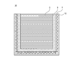
- FIG. 9A shows an artificial satellite, which is an example of 20 including a heat storage material.
- the article 20 as an artificial satellite includes a heat control unit 11, a control unit 12, a power generation unit 13, and a communication unit 14.
- 9B shows a cross-sectional view taken along the line AA'of the heat control unit 11 in FIG. 9A.
- a metal layer 1 is provided on the heat storage member 5.
- the metal layer 1 is adhered to the container 5 accommodating the heat storage member 5 via an adhesive layer 6 located between the metal layer 1 and the heat storage member 5.
- paraffin can be used as the heat storage member 5.
- the heat control unit 11 can store heat with sunlight.
- a heat radiating material can be provided on the article 20 such as an artificial satellite.
- a predetermined portion of the article 20 for example, the control unit 12
- heat can be stored in the heat storage material of the heat control unit 11.
- the predetermined portion for example, the control unit 12
- the predetermined temperature for example, the control unit 12
- the predetermined temperature for example, the control unit 12
- the predetermined temperature for example, the control unit 12
- the article 20 as an artificial satellite can perform at least one of deformation and displacement so that such heat storage and heat dissipation can be switched.
- the shape in which the heat storage material faces the outside of the artificial satellite (for example, the side opposite to the control unit 12) and the heat radiating material faces the inside of the artificial satellite (for example, the side of the control unit 12) is the heat storage shape.
- the shape in which the heat radiating material faces the outside of the artificial satellite (for example, the side opposite to the control unit 12) and the heat storage material faces the inside of the artificial satellite (for example, the side of the control unit 12) is the heat radiating shape. Then, the artificial satellite can be deformed so as to switch between the heat storage shape and the heat dissipation shape.
- the artificial satellite takes a posture in which the heat storage material faces the heat source around the artificial satellite (for example, the sun) and the heat radiating material faces the opposite side (for example, the earth) from the heat source around the artificial satellite. It can also be displaced.
- the heat storage material of this embodiment can be used for hybrid type photovoltaic power generation in combination with a photovoltaic power generation cell.
- Photovoltaic cells can use silicon, organic semiconductors, organic-inorganic perovskite semiconductors, and the like.
- the transmitted light of the solar power generation cell is absorbed by the heat storage material, and by suppressing the radiation, heat is efficiently stored and the solar heat is stored. It can be used.
- the translucent heat insulating material for example, airgel or xerogel can be used.
- FIG. 10 shows a solar panel, which is an example of an article 20 containing a heat storage material, in FIG. 8.
- oil can be used as the heat storage member 5.
- the heat storage member 5 (oil) is housed in the container 9.
- a metal layer 1 is provided on the outside of the container 9.
- the container 5 is located between the heat storage member 5 and the metal layer 1.
- the metal layer 1 is adhered to the heat storage member 5 via the adhesive layer 6, and the adhesive layer 6 is located between the container 5 and the metal layer 1.
- a photovoltaic power generation cell 15 is provided on the outside of the metal layer 1. Silicon can be used for the photovoltaic power generation cell 15.
- the metal layer 1 is located between the photovoltaic power generation cell 15 and the heat storage member 5.
- a heat insulating material 10 is provided on the outside of the photovoltaic power generation cell 15.
- the photovoltaic power generation cell 15 is located between the heat insulating material 10 and the metal layer 1.
- a photovoltaic power generation cell 15 is provided between the heat storage member 5 and the heat storage material having the metal layer 1 provided on the heat storage member 5 and the heat insulating material 10.
- the heat insulating material 10 for example, vacuum-filled glass can be used.
- a hybrid type photovoltaic power generation system can be configured, and solar power can be generated and stored.
- a system that uses the heat energy of the sun can be called a solar heat utilization system.
- the solar heat utilization system is the above-mentioned solar hot water supply system or solar thermal power generation system.
- the solar heat utilization system includes the heat storage material of the present embodiment, and the solar heat utilization system includes an article provided with the heat storage material.
- the article provided with the heat storage material may be provided with a heat insulating material or a heat radiating material in addition to the heat storage material.
- the heat insulating material and the heat radiating material in the article provided with the heat storage material can be fixed to the heat storage material.
- the solar heat utilization system may include other articles such as piping, a heat medium, and a steam turbine, in addition to the articles provided with the heat storage material. Other articles in the solar heat utilization system need not be fixed to the article provided with the heat storage material.
- a system that utilizes the light energy of the sun can be called a solar utilization system.
- the solar utilization system is the above-mentioned solar power generation system or solar lighting system.
- the solar utilization system includes the heat storage material of the present embodiment, and the solar utilization system includes an article provided with the heat storage material.
- the article provided with the heat storage material may be provided with a heat insulating material or a heat radiating material in addition to the heat storage material.
- the heat insulating material and the heat radiating material in the article provided with the heat storage material can be fixed to the heat storage material.
- the solar utilization system may include other articles such as wiring, a battery, and a power conditioner, in addition to the article provided with the heat storage material. Other articles in the solar heat utilization system need not be fixed to the article provided with the heat storage material.
- a solar heat utilization system or a solar utilization system can also be called a solar system.
- Solar systems can include solar collectors, solar pots, and solar panels.
- a lens reflectance measuring device (trade name: USPM-RU III, manufactured by Olympus Corporation) was used for the reflectance spectrum measurement in the visible light region of the examples.
- a Fourier transform infrared spectrophotometer (FT / IR-6600, manufactured by Nippon Spectroscopy Co., Ltd.) was used for the reflectance spectrum measurement in the infrared region of the example.
- Example 1 Aluminum-sec-butoxide (hereinafter, also referred to as “Al (O-sec-Bu) 3 ”) and ethyl acetoacetate (hereinafter, also referred to as “EtOAc Ac”) are also referred to as 2-propanol (hereinafter, also referred to as “IPA”). ), And the mixture was stirred at room temperature for about 3 hours to prepare an alumina sol solution.
- a 0.01 M dilute hydrochloric acid aqueous solution was added to the alumina sol solution so that the hydrochloric acid additive was doubled in terms of molar ratio with respect to Al (O-sec-Bu) 3 , and the mixture was refluxed for about 6 hours to form a sol-gel coating.
- a solution was prepared.
- a sol-gel coating liquid was applied onto a quartz glass substrate as a base material by a spin coating method to form a coating film. Then, the coating film was heat-treated at 100 ° C. for 1 hour to obtain a transparent alumina gel film. Next, the alumina gel film was immersed in warm water at 80 ° C. for 30 minutes and then dried at 100 ° C. for 10 minutes to form an alumina layer having a fine uneven shape.
- a palladium chloride aqueous solution was applied on an alumina layer having a fine uneven shape by a spin coating method, and then dried at 100 ° C. Then, it was immersed in a nickel-phosphorus plating solution (phosphorus content of about 10 wt%) set at 80 ° C. for 1 minute to form a fine uneven shape and a nickel layer as a metal layer.
- a nickel-phosphorus plating solution phosphorus content of about 10 wt% set at 80 ° C. for 1 minute to form a fine uneven shape and a nickel layer as a metal layer.
- An epoxy resin to be an adhesive layer was applied and cured on the surface of the obtained metal layer opposite to the alumina layer having a fine uneven shape, and a PET film was adhered as a base material of a heat storage member via the adhesive layer. After that, it was peeled off from the quartz glass substrate. The base material was attached to a quartz cell containing water as a heat storage material.
- Example 1 a nickel layer formed on an alumina layer having a fine uneven shape is cut out with a dicing saw and then sliced in the cross-sectional direction by a focus ion beam (FIB) method to form a cross section.
- FIB focus ion beam
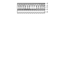
- the cross-sectional observation was performed using a scanning transmission electron microscope (trade name: HD-2300, manufactured by Hitachi High-Technologies Corporation). From the observation image shown in FIG. 4, the nickel fine uneven shape 2 is formed so as to fill the inside of the alumina plate-like crystal which is the fine uneven shape 3 of the metal oxide formed from the alumina gel film on the base base material 8.
- the average height of the obtained fine concavo-convex shape 2 of Example 1 was 323 nm, the average height of the fine concavo-convex shape 3 was 255 nm, and the film thickness of the film 7 containing aluminum was 68 nm.
- the average surface roughness Ra'of the surface was 1.0 nm, and the specific surface area was 1.0.
- the reflectance spectrum in the visible light region and the reflectance spectrum in the infrared region of Example 1 were measured.
- a lens reflectivity measuring device (trade name: USPM-RU III, manufactured by Olympus Co., Ltd.) is used for the reflectance spectrum measurement, and a Fourier transform infrared spectrophotometer (trade name: FT) is used for the infrared region reflectance spectrum measurement.
- FT Fourier transform infrared spectrophotometer
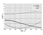
- Table 1 shows the reflectances in the visible light and infrared regions obtained by the reflectance spectrum measurements in the visible light region and the infrared region of Example 1. From FIG. 5, it can be said that Example 1 has excellent absorbance because the reflectance in the visible light region is low.
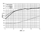
- Example 1 has excellent heat storage property because the reflectance increases toward the long wavelength side in the mid-infrared and far-infrared regions.
- Comparative Example 1 was inferior to the sample of Example 1, but had low reflectance in the visible light to near infrared region.
- the sample of Comparative Example 1 was inferior to that of Example 1 in the reflectance in the mid-infrared region and the far-infrared region.
- Example 2 In the same manner as in Example 1, an alumina sol solution was prepared and used by a spin coating method to be applied onto a quartz glass substrate as a base substrate to form a coating film. Then, the coating film was heat-treated at 100 ° C. for 1 hour to obtain a transparent alumina gel film. Next, the alumina gel film was immersed in warm water at 80 ° C. for 30 minutes and then dried at 100 ° C. for 10 minutes to form an alumina layer having a fine uneven shape.
- a palladium chloride aqueous solution was applied on an alumina layer having a fine uneven shape by a spin coating method, and then dried at room temperature. Then, it was immersed in a nickel-phosphorus plating solution (phosphorus content of about 10 wt%) set at 80 ° C. for 20 minutes to form a fine uneven shape and a nickel layer as a metal layer.
- a nickel-phosphorus plating solution phosphorus content of about 10 wt% set at 80 ° C. for 20 minutes to form a fine uneven shape and a nickel layer as a metal layer.
- the total film thickness obtained was about 10 ⁇ m.
- the average height of the fine concavo-convex shape of the obtained film was 303 nm, the average height of the fine concavo-convex shape was 233 nm, and the film thickness of the film containing aluminum was 70 nm. Further, the average surface roughness Ra'of the film was 1.0 nm, and the specific surface area was 1.0.
- the film was manufactured by changing the number of laminated gel films and the etching conditions.
- Example 3 A film was produced in the same manner as in Example 2, and the film peeled from the quartz glass substrate was etched with a 3M aqueous sodium hydroxide solution at room temperature for 50 hours as an etching step to produce the film.
- the average height of the fine uneven shape of the obtained film was 251 nm
- the average height of the fine uneven shape was 213 nm
- the average surface roughness Ra' was 5.0 nm
- the specific surface area was 1.1.
- the result of the reflectance spectrum measurement in the visible light region is shown in FIG. 5, and the result of the reflectance spectrum measurement in the infrared region is shown in FIG.
- a cross section was obtained by the FIB method, and the cross section was observed by SEM.
- the cross-sectional observation was performed using a scanning electron microscope (trade name: ULTRA55, manufactured by Carl Zeiss). From the observation image shown in FIG. 7, the fine uneven shape of nickel 2 was formed on the nickel layer which is the metal layer 1, and a small amount of alumina remained on the fine uneven shape 2.
- the proportion of Al element was relatively low from the surface toward the inside in the film thickness direction of the cross section, while the proportion of Ni element was high.
- Example 4 A film was produced in the same manner as in Example 3 except that the etching process was performed at room temperature for 47 hours using a 7.5 M aqueous sodium hydroxide solution.
- the average height of the fine uneven shape of the obtained film was 235 nm, the average surface roughness Ra'was 18 nm, and the specific surface area was 1.4.
- Example 5 A film was produced in the same manner as in Example 3 except that a nickel-phosphorus plating solution (phosphorus content of about 1 to 2 wt%) was used as the plating solution.
- the average height of the fine uneven shape of the obtained film was 272 nm, the average surface roughness Ra'was 3.8 nm, and the specific surface area was 1.1.
- Example 6 The alumina sol solution shown in Example 2 was prepared and applied onto a quartz glass substrate as a base substrate by a spin coating method to form a coating film. After that, the coating film is heat-treated at 100 ° C. for 1 hour, and the same film coating and drying process is repeated again to increase the number of alumina gel films to two, and to form a transparent alumina gel film as a film containing aluminum. Obtained. After that, a film was produced in the same manner as in Example 2. The average height of the fine uneven shape of the obtained film was 371 nm, the average height of the fine uneven shape was 306 nm, the average surface roughness Ra'was 1.1 nm, and the specific surface area was 1.0.
- Example 7 After peeling the metal film provided with the alumina layer from the quartz glass substrate, the film was manufactured in the same manner as in Example 6 except that the metal film provided with the alumina layer was etched with a 3M sodium hydroxide aqueous solution at room temperature for 50 hours as an etching step.
- the average height of the fine uneven shape of the obtained film was 315 nm, the average surface roughness Ra'was 10 nm, and the specific surface area was 1.2.
- Example 8 A film was produced in the same manner as in Example 7 except that the etching step was performed by etching at room temperature for 50 hours using a 7.5 M aqueous sodium hydroxide solution.
- the average height of the fine uneven shape of the obtained film was 303 nm, the average surface roughness Ra'was 27 nm, and the specific surface area was 1.7.
- Example 9 A film was produced in the same manner as in Example 2 except that the number of laminated alumina gel films was three.
- the average height of the fine uneven shape of the obtained film was 419 nm
- the average height of the fine uneven shape was 374 nm
- the average surface roughness Ra' was 1.2 nm
- the specific surface area was 1.0.
- Example 10 After peeling the metal film provided with the alumina layer from the quartz glass substrate, the film was manufactured in the same manner as in Example 9 except that the metal film provided with the alumina layer was etched with a 3M sodium hydroxide aqueous solution at room temperature for 50 hours in the etching step.
- the average height of the fine uneven shape of the obtained film was 354 nm, the average surface roughness Ra'was 16 nm, and the specific surface area was 1.3.
- Example 11 A film was produced in the same manner as in Example 10 except that the etching process was performed at room temperature for 45 hours using a 6 M aqueous sodium hydroxide solution.
- the average height of the fine uneven shape of the obtained film was 346 nm, the average surface roughness Ra'was 35 nm, and the specific surface area was 2.1.
- Table 1 shows the reflectances of the visible light region and the infrared region obtained by the reflection spectrum measurement of the visible light region and the infrared region of the samples manufactured in Examples 1 to 11 and Comparative Example 1.
- Example 12 A sample was produced by putting 40 ml of water in a quartz cell of 10 mm ⁇ 10 mm ⁇ 45 mm in the same manner as in Example 1. The sample left at room temperature (25 ° C.) was irradiated with a 150 W halogen lamp at a distance of 10 mm. After the irradiation, the irradiation of the halogen lamp was stopped and the mixture was left for 10 minutes, and then the temperature of the water was measured with a thermocouple. The results are shown in Table 2.
- Comparative Example 2 It was evaluated in the same manner as the sample produced in the same manner as in Example 12 with the absorbent material of Comparative Example 1. The results are shown in Table 2.
- Example 12 It was found that heat is stored more efficiently in Example 12 because the temperature raised by irradiating the same energy is higher than that in Comparative Example 2.
- the heat storage material of the present invention is excellent in both absorbency and heat storage.
- the present invention it is possible to provide an absorbent heat storage film and a heat storage member that absorb visible light and near infrared rays (low reflectance) and emit small far infrared rays (high reflectance), which are normally incompatible.
- the absorption heat storage film and the heat storage member of the present invention can be used as a heat storage member for space-related equipment such as artificial satellites and solar thermal power generation, and can also be used as an exterior film, a solar collector, and the like.
Landscapes
- Engineering & Computer Science (AREA)
- Mechanical Engineering (AREA)
- General Engineering & Computer Science (AREA)
- Physics & Mathematics (AREA)
- Thermal Sciences (AREA)
- Life Sciences & Earth Sciences (AREA)
- Sustainable Energy (AREA)
- Combustion & Propulsion (AREA)
- Chemical & Material Sciences (AREA)
- Sustainable Development (AREA)
- Remote Sensing (AREA)
- Aviation & Aerospace Engineering (AREA)
- Health & Medical Sciences (AREA)
- Biodiversity & Conservation Biology (AREA)
- Environmental & Geological Engineering (AREA)
- Environmental Sciences (AREA)
- General Health & Medical Sciences (AREA)
- Toxicology (AREA)
- Laminated Bodies (AREA)
Priority Applications (3)
| Application Number | Priority Date | Filing Date | Title |
|---|---|---|---|
| CN202180066257.5A CN116209872A (zh) | 2020-09-28 | 2021-09-22 | 储热装置及其制造方法 |
| JP2022552017A JP7826213B2 (ja) | 2020-09-28 | 2021-09-22 | 蓄熱材、およびその製造方法 |
| US18/189,139 US20230228460A1 (en) | 2020-09-28 | 2023-03-23 | Heat storage device and method for producing the same |
Applications Claiming Priority (2)
| Application Number | Priority Date | Filing Date | Title |
|---|---|---|---|
| JP2020-162586 | 2020-09-28 | ||
| JP2020162586 | 2020-09-28 |
Related Child Applications (1)
| Application Number | Title | Priority Date | Filing Date |
|---|---|---|---|
| US18/189,139 Continuation US20230228460A1 (en) | 2020-09-28 | 2023-03-23 | Heat storage device and method for producing the same |
Publications (1)
| Publication Number | Publication Date |
|---|---|
| WO2022065340A1 true WO2022065340A1 (ja) | 2022-03-31 |
Family
ID=80845451
Family Applications (1)
| Application Number | Title | Priority Date | Filing Date |
|---|---|---|---|
| PCT/JP2021/034708 Ceased WO2022065340A1 (ja) | 2020-09-28 | 2021-09-22 | 蓄熱材、およびその製造方法 |
Country Status (4)
| Country | Link |
|---|---|
| US (1) | US20230228460A1 (https=) |
| JP (1) | JP7826213B2 (https=) |
| CN (1) | CN116209872A (https=) |
| WO (1) | WO2022065340A1 (https=) |
Citations (8)
| Publication number | Priority date | Publication date | Assignee | Title |
|---|---|---|---|---|
| JPS57155396A (en) * | 1981-03-20 | 1982-09-25 | Matsushita Electric Works Ltd | Solar heat absorbing object |
| JPH077976A (ja) * | 1993-06-17 | 1995-01-10 | Hitachi Ltd | 発電ユニットとこれを用いた発電システム及びその運転方法 |
| JP2012007787A (ja) * | 2010-06-23 | 2012-01-12 | Shunsaku Nakauchi | 真空平板式太陽熱コレクター |
| JP2012093004A (ja) * | 2010-10-25 | 2012-05-17 | Ibiden Co Ltd | 集熱レシーバー及び太陽熱発電装置 |
| JP2012201589A (ja) * | 2011-03-28 | 2012-10-22 | Shinshu Univ | 光吸収膜、その製造方法およびそれを用いた太陽光集熱器 |
| JP2013019574A (ja) * | 2011-07-08 | 2013-01-31 | Murata Mfg Co Ltd | 太陽光選択吸収膜形成用シート、太陽光選択吸収膜の製造方法、および、ソーラーシステムの製造方法 |
| EP2881440A1 (en) * | 2013-12-09 | 2015-06-10 | Rigas Tehniska universitate | Double-layer coating on alloy steel |
| WO2018138965A1 (ja) * | 2017-01-24 | 2018-08-02 | ナノフロンティアテクノロジー株式会社 | 太陽熱発電用集熱膜およびその製造方法 |
Family Cites Families (9)
| Publication number | Priority date | Publication date | Assignee | Title |
|---|---|---|---|---|
| DE2616662C2 (de) * | 1976-04-15 | 1984-02-02 | Dornier System Gmbh, 7990 Friedrichshafen | Verfahren zur herstellung einer selektiven solarabsorberschicht auf aluminium |
| US4316048A (en) * | 1980-06-20 | 1982-02-16 | International Business Machines Corporation | Energy conversion |
| JP4870544B2 (ja) * | 2006-12-25 | 2012-02-08 | 富士フイルム株式会社 | 微細構造体の製造方法および微細構造体 |
| US8546685B2 (en) * | 2009-07-03 | 2013-10-01 | Kaneka Corporation | Crystalline silicon based solar cell and method for manufacturing thereof |
| US20110185728A1 (en) * | 2010-02-01 | 2011-08-04 | General Electric Company | High efficiency solar thermal receiver |
| FR3016875B1 (fr) * | 2014-01-30 | 2016-03-04 | Commissariat Energie Atomique | Structure photonique de surface en materiau refractaire et son procede de realisation. |
| WO2017073564A1 (ja) * | 2015-10-26 | 2017-05-04 | 京セラ株式会社 | 熱光変換素子 |
| CN111249757A (zh) * | 2018-12-03 | 2020-06-09 | 中国科学院宁波材料技术与工程研究所 | 碳纤维光热转换材料及其在纯化回收多介质溶剂中的用途 |
| JP2023046196A (ja) * | 2021-09-22 | 2023-04-03 | 株式会社イノアック住環境 | 道路構造物の製造方法および道路構造物 |
-
2021
- 2021-09-22 CN CN202180066257.5A patent/CN116209872A/zh active Pending
- 2021-09-22 JP JP2022552017A patent/JP7826213B2/ja active Active
- 2021-09-22 WO PCT/JP2021/034708 patent/WO2022065340A1/ja not_active Ceased
-
2023
- 2023-03-23 US US18/189,139 patent/US20230228460A1/en active Pending
Patent Citations (8)
| Publication number | Priority date | Publication date | Assignee | Title |
|---|---|---|---|---|
| JPS57155396A (en) * | 1981-03-20 | 1982-09-25 | Matsushita Electric Works Ltd | Solar heat absorbing object |
| JPH077976A (ja) * | 1993-06-17 | 1995-01-10 | Hitachi Ltd | 発電ユニットとこれを用いた発電システム及びその運転方法 |
| JP2012007787A (ja) * | 2010-06-23 | 2012-01-12 | Shunsaku Nakauchi | 真空平板式太陽熱コレクター |
| JP2012093004A (ja) * | 2010-10-25 | 2012-05-17 | Ibiden Co Ltd | 集熱レシーバー及び太陽熱発電装置 |
| JP2012201589A (ja) * | 2011-03-28 | 2012-10-22 | Shinshu Univ | 光吸収膜、その製造方法およびそれを用いた太陽光集熱器 |
| JP2013019574A (ja) * | 2011-07-08 | 2013-01-31 | Murata Mfg Co Ltd | 太陽光選択吸収膜形成用シート、太陽光選択吸収膜の製造方法、および、ソーラーシステムの製造方法 |
| EP2881440A1 (en) * | 2013-12-09 | 2015-06-10 | Rigas Tehniska universitate | Double-layer coating on alloy steel |
| WO2018138965A1 (ja) * | 2017-01-24 | 2018-08-02 | ナノフロンティアテクノロジー株式会社 | 太陽熱発電用集熱膜およびその製造方法 |
Also Published As
| Publication number | Publication date |
|---|---|
| US20230228460A1 (en) | 2023-07-20 |
| JP7826213B2 (ja) | 2026-03-09 |
| JPWO2022065340A1 (https=) | 2022-03-31 |
| CN116209872A (zh) | 2023-06-02 |
Similar Documents
| Publication | Publication Date | Title |
|---|---|---|
| Banik et al. | Efficient thin polymer coating as a selective thermal emitter for passive daytime radiative cooling | |
| CN102061112B (zh) | 复合金属有机骨架材料胶体溶液的制备方法及其在光学涂层上的应用 | |
| CN101019212B (zh) | 半导体基板的制造方法、太阳能用半导体基板及蚀刻液 | |
| Wu et al. | TiOx/Ag/TiOx multilayer for application as a transparent conductive electrode and heat mirror | |
| JP5538695B2 (ja) | スーパーストレート型薄膜太陽電池用の複合膜 | |
| JP7844333B2 (ja) | 吸光遮熱膜、吸光遮熱部材、および物品、並びにそれらの製造方法 | |
| TW201119063A (en) | Solar cell device | |
| JP2013151103A (ja) | 透明積層フィルム | |
| JP7826213B2 (ja) | 蓄熱材、およびその製造方法 | |
| JP7672791B2 (ja) | 吸光遮熱膜、吸光遮熱部材、および物品、並びにそれらの製造方法 | |
| JP2009023887A (ja) | カーボン含有チタンオキシナイトライドと、それを用いた選択吸収膜および太陽光集熱器と、多孔体 | |
| JP2007331296A (ja) | 透明積層フィルムおよび透明積層体 | |
| JP2010087479A (ja) | サブストレート型太陽電池用の複合膜及びその製造方法 | |
| JP5446102B2 (ja) | ディスプレイ用耐湿熱性フィルム | |
| WO2020203761A1 (ja) | 吸光遮熱膜、吸光遮熱部材、および物品、並びにそれらの製造方法 | |
| JP2020177923A (ja) | フレキシブル発光デバイス、照明装置および画像表示装置 | |
| Wang et al. | Recent progress in outermost surface engineering for solar panels | |
| JP2012094830A (ja) | 太陽電池向け透明導電膜用組成物および透明導電膜 | |
| JP2012151387A (ja) | 太陽電池向け透明導電膜用組成物および透明導電膜 | |
| CN115557712A (zh) | 金银钯三元纳米晶/聚苯乙烯微纳米二级结构复合材料及其制备方法和其太阳能蒸发器 | |
| JP2010278048A (ja) | スーパーストレート型薄膜太陽電池用の複合膜及びその製造方法 | |
| JP6134223B2 (ja) | 光透過性積層体 | |
| CN221466588U (zh) | 一种光伏组件 | |
| TWI314760B (en) | Method for manufacturing transparent conductive thin films | |
| CN121908702A (zh) | 一种红外阻隔与辐射制冷叠层薄膜及其制备方法和应用 |
Legal Events
| Date | Code | Title | Description |
|---|---|---|---|
| 121 | Ep: the epo has been informed by wipo that ep was designated in this application |
Ref document number: 21872469 Country of ref document: EP Kind code of ref document: A1 |
|
| ENP | Entry into the national phase |
Ref document number: 2022552017 Country of ref document: JP Kind code of ref document: A |
|
| NENP | Non-entry into the national phase |
Ref country code: DE |
|
| 122 | Ep: pct application non-entry in european phase |
Ref document number: 21872469 Country of ref document: EP Kind code of ref document: A1 |