WO2022065340A1 - Heat storage material, and method for manufacturing same - Google Patents
Heat storage material, and method for manufacturing same Download PDFInfo
- Publication number
- WO2022065340A1 WO2022065340A1 PCT/JP2021/034708 JP2021034708W WO2022065340A1 WO 2022065340 A1 WO2022065340 A1 WO 2022065340A1 JP 2021034708 W JP2021034708 W JP 2021034708W WO 2022065340 A1 WO2022065340 A1 WO 2022065340A1
- Authority
- WO
- WIPO (PCT)
- Prior art keywords
- heat storage
- storage material
- heat
- metal layer
- film
- Prior art date
Links
- 238000005338 heat storage Methods 0.000 title claims description 223
- 239000011232 storage material Substances 0.000 title claims description 116
- 238000004519 manufacturing process Methods 0.000 title claims description 20
- 238000000034 method Methods 0.000 title description 40
- 229910052751 metal Inorganic materials 0.000 claims abstract description 136
- 239000002184 metal Substances 0.000 claims abstract description 132
- 239000010410 layer Substances 0.000 claims description 127
- PNEYBMLMFCGWSK-UHFFFAOYSA-N aluminium oxide Inorganic materials [O-2].[O-2].[O-2].[Al+3].[Al+3] PNEYBMLMFCGWSK-UHFFFAOYSA-N 0.000 claims description 71
- 239000000463 material Substances 0.000 claims description 59
- 229910044991 metal oxide Inorganic materials 0.000 claims description 58
- 150000004706 metal oxides Chemical class 0.000 claims description 58
- PXHVJJICTQNCMI-UHFFFAOYSA-N Nickel Chemical compound [Ni] PXHVJJICTQNCMI-UHFFFAOYSA-N 0.000 claims description 46
- 229910052782 aluminium Inorganic materials 0.000 claims description 45
- XAGFODPZIPBFFR-UHFFFAOYSA-N aluminium Chemical compound [Al] XAGFODPZIPBFFR-UHFFFAOYSA-N 0.000 claims description 34
- XLYOFNOQVPJJNP-UHFFFAOYSA-N water Substances O XLYOFNOQVPJJNP-UHFFFAOYSA-N 0.000 claims description 27
- 238000010248 power generation Methods 0.000 claims description 24
- 229910052759 nickel Inorganic materials 0.000 claims description 22
- 230000003746 surface roughness Effects 0.000 claims description 20
- 239000013078 crystal Substances 0.000 claims description 18
- 239000011810 insulating material Substances 0.000 claims description 18
- 239000012790 adhesive layer Substances 0.000 claims description 13
- 230000005855 radiation Effects 0.000 claims description 11
- 150000003839 salts Chemical class 0.000 claims description 9
- 229920005989 resin Polymers 0.000 claims description 8
- 239000011347 resin Substances 0.000 claims description 8
- 229910052725 zinc Inorganic materials 0.000 claims description 6
- 239000011701 zinc Substances 0.000 claims description 6
- HCHKCACWOHOZIP-UHFFFAOYSA-N Zinc Chemical compound [Zn] HCHKCACWOHOZIP-UHFFFAOYSA-N 0.000 claims description 5
- VYZAMTAEIAYCRO-UHFFFAOYSA-N Chromium Chemical compound [Cr] VYZAMTAEIAYCRO-UHFFFAOYSA-N 0.000 claims description 4
- 229910052804 chromium Inorganic materials 0.000 claims description 4
- 239000011651 chromium Substances 0.000 claims description 4
- 239000011521 glass Substances 0.000 claims description 4
- 239000003921 oil Substances 0.000 claims description 4
- 239000012188 paraffin wax Substances 0.000 claims description 3
- 239000000919 ceramic Substances 0.000 claims description 2
- 238000006073 displacement reaction Methods 0.000 claims description 2
- 239000000835 fiber Substances 0.000 claims description 2
- 239000000123 paper Substances 0.000 claims description 2
- 239000004576 sand Substances 0.000 claims description 2
- 239000002023 wood Substances 0.000 claims description 2
- -1 polyethylene terephthalate Polymers 0.000 description 31
- 108010025899 gelatin film Proteins 0.000 description 29
- 239000000243 solution Substances 0.000 description 29
- 239000002585 base Substances 0.000 description 27
- 238000005259 measurement Methods 0.000 description 23
- 238000000576 coating method Methods 0.000 description 22
- HEMHJVSKTPXQMS-UHFFFAOYSA-M Sodium hydroxide Chemical compound [OH-].[Na+] HEMHJVSKTPXQMS-UHFFFAOYSA-M 0.000 description 21
- 238000005530 etching Methods 0.000 description 21
- 239000011248 coating agent Substances 0.000 description 20
- 238000010521 absorption reaction Methods 0.000 description 17
- 238000009713 electroplating Methods 0.000 description 17
- 238000007747 plating Methods 0.000 description 15
- 230000008569 process Effects 0.000 description 15
- 238000000985 reflectance spectrum Methods 0.000 description 15
- 239000000758 substrate Substances 0.000 description 14
- VYPSYNLAJGMNEJ-UHFFFAOYSA-N Silicium dioxide Chemical compound O=[Si]=O VYPSYNLAJGMNEJ-UHFFFAOYSA-N 0.000 description 11
- 239000007788 liquid Substances 0.000 description 11
- 150000001875 compounds Chemical class 0.000 description 10
- 230000000052 comparative effect Effects 0.000 description 9
- 238000010586 diagram Methods 0.000 description 9
- 238000007772 electroless plating Methods 0.000 description 9
- 238000002835 absorbance Methods 0.000 description 8
- 239000007864 aqueous solution Substances 0.000 description 8
- 239000000523 sample Substances 0.000 description 8
- XEKOWRVHYACXOJ-UHFFFAOYSA-N Ethyl acetate Chemical compound CCOC(C)=O XEKOWRVHYACXOJ-UHFFFAOYSA-N 0.000 description 7
- VEXZGXHMUGYJMC-UHFFFAOYSA-N Hydrochloric acid Chemical compound Cl VEXZGXHMUGYJMC-UHFFFAOYSA-N 0.000 description 7
- 239000002250 absorbent Substances 0.000 description 7
- 230000002745 absorbent Effects 0.000 description 7
- 238000004528 spin coating Methods 0.000 description 7
- LFQSCWFLJHTTHZ-UHFFFAOYSA-N Ethanol Chemical compound CCO LFQSCWFLJHTTHZ-UHFFFAOYSA-N 0.000 description 6
- KFZMGEQAYNKOFK-UHFFFAOYSA-N Isopropanol Chemical compound CC(C)O KFZMGEQAYNKOFK-UHFFFAOYSA-N 0.000 description 6
- XUIMIQQOPSSXEZ-UHFFFAOYSA-N Silicon Chemical compound [Si] XUIMIQQOPSSXEZ-UHFFFAOYSA-N 0.000 description 5
- 238000007598 dipping method Methods 0.000 description 5
- 229920000620 organic polymer Polymers 0.000 description 5
- 229910052710 silicon Inorganic materials 0.000 description 5
- 239000010703 silicon Substances 0.000 description 5
- 239000003381 stabilizer Substances 0.000 description 5
- WOZZOSDBXABUFO-UHFFFAOYSA-N tri(butan-2-yloxy)alumane Chemical compound [Al+3].CCC(C)[O-].CCC(C)[O-].CCC(C)[O-] WOZZOSDBXABUFO-UHFFFAOYSA-N 0.000 description 5
- ATUUSOSLBXVJKL-UHFFFAOYSA-N 3-ethylpentanoic acid Chemical compound CCC(CC)CC(O)=O ATUUSOSLBXVJKL-UHFFFAOYSA-N 0.000 description 4
- QTBSBXVTEAMEQO-UHFFFAOYSA-N Acetic acid Chemical compound CC(O)=O QTBSBXVTEAMEQO-UHFFFAOYSA-N 0.000 description 4
- OAICVXFJPJFONN-UHFFFAOYSA-N Phosphorus Chemical compound [P] OAICVXFJPJFONN-UHFFFAOYSA-N 0.000 description 4
- QAOWNCQODCNURD-UHFFFAOYSA-N Sulfuric acid Chemical compound OS(O)(=O)=O QAOWNCQODCNURD-UHFFFAOYSA-N 0.000 description 4
- 230000015572 biosynthetic process Effects 0.000 description 4
- 238000002149 energy-dispersive X-ray emission spectroscopy Methods 0.000 description 4
- 239000000203 mixture Substances 0.000 description 4
- 239000003960 organic solvent Substances 0.000 description 4
- 239000011574 phosphorus Substances 0.000 description 4
- 229910052698 phosphorus Inorganic materials 0.000 description 4
- ZWEHNKRNPOVVGH-UHFFFAOYSA-N 2-Butanone Chemical compound CCC(C)=O ZWEHNKRNPOVVGH-UHFFFAOYSA-N 0.000 description 3
- CSCPPACGZOOCGX-UHFFFAOYSA-N Acetone Chemical compound CC(C)=O CSCPPACGZOOCGX-UHFFFAOYSA-N 0.000 description 3
- LYCAIKOWRPUZTN-UHFFFAOYSA-N Ethylene glycol Chemical compound OCCO LYCAIKOWRPUZTN-UHFFFAOYSA-N 0.000 description 3
- OKKJLVBELUTLKV-UHFFFAOYSA-N Methanol Chemical compound OC OKKJLVBELUTLKV-UHFFFAOYSA-N 0.000 description 3
- 239000004721 Polyphenylene oxide Substances 0.000 description 3
- KWYUFKZDYYNOTN-UHFFFAOYSA-M Potassium hydroxide Chemical compound [OH-].[K+] KWYUFKZDYYNOTN-UHFFFAOYSA-M 0.000 description 3
- YXFVVABEGXRONW-UHFFFAOYSA-N Toluene Chemical compound CC1=CC=CC=C1 YXFVVABEGXRONW-UHFFFAOYSA-N 0.000 description 3
- 239000002253 acid Substances 0.000 description 3
- 239000000853 adhesive Substances 0.000 description 3
- 230000001070 adhesive effect Effects 0.000 description 3
- 230000005540 biological transmission Effects 0.000 description 3
- 150000001732 carboxylic acid derivatives Chemical class 0.000 description 3
- MTHSVFCYNBDYFN-UHFFFAOYSA-N diethylene glycol Chemical compound OCCOCCO MTHSVFCYNBDYFN-UHFFFAOYSA-N 0.000 description 3
- 235000019439 ethyl acetate Nutrition 0.000 description 3
- 150000004820 halides Chemical class 0.000 description 3
- 238000007654 immersion Methods 0.000 description 3
- 229910021645 metal ion Inorganic materials 0.000 description 3
- 229910001453 nickel ion Inorganic materials 0.000 description 3
- PIBWKRNGBLPSSY-UHFFFAOYSA-L palladium(II) chloride Chemical compound Cl[Pd]Cl PIBWKRNGBLPSSY-UHFFFAOYSA-L 0.000 description 3
- OFNHPGDEEMZPFG-UHFFFAOYSA-N phosphanylidynenickel Chemical compound [P].[Ni] OFNHPGDEEMZPFG-UHFFFAOYSA-N 0.000 description 3
- 238000005240 physical vapour deposition Methods 0.000 description 3
- 238000004544 sputter deposition Methods 0.000 description 3
- ARXJGSRGQADJSQ-UHFFFAOYSA-N 1-methoxypropan-2-ol Chemical compound COCC(C)O ARXJGSRGQADJSQ-UHFFFAOYSA-N 0.000 description 2
- XBIUWALDKXACEA-UHFFFAOYSA-N 3-[bis(2,4-dioxopentan-3-yl)alumanyl]pentane-2,4-dione Chemical compound CC(=O)C(C(C)=O)[Al](C(C(C)=O)C(C)=O)C(C(C)=O)C(C)=O XBIUWALDKXACEA-UHFFFAOYSA-N 0.000 description 2
- QGZKDVFQNNGYKY-UHFFFAOYSA-N Ammonia Chemical compound N QGZKDVFQNNGYKY-UHFFFAOYSA-N 0.000 description 2
- IJGRMHOSHXDMSA-UHFFFAOYSA-N Atomic nitrogen Chemical compound N#N IJGRMHOSHXDMSA-UHFFFAOYSA-N 0.000 description 2
- FERIUCNNQQJTOY-UHFFFAOYSA-N Butyric acid Chemical compound CCCC(O)=O FERIUCNNQQJTOY-UHFFFAOYSA-N 0.000 description 2
- 239000004215 Carbon black (E152) Substances 0.000 description 2
- RYGMFSIKBFXOCR-UHFFFAOYSA-N Copper Chemical compound [Cu] RYGMFSIKBFXOCR-UHFFFAOYSA-N 0.000 description 2
- RGSFGYAAUTVSQA-UHFFFAOYSA-N Cyclopentane Chemical compound C1CCCC1 RGSFGYAAUTVSQA-UHFFFAOYSA-N 0.000 description 2
- RTZKZFJDLAIYFH-UHFFFAOYSA-N Diethyl ether Chemical compound CCOCC RTZKZFJDLAIYFH-UHFFFAOYSA-N 0.000 description 2
- YNQLUTRBYVCPMQ-UHFFFAOYSA-N Ethylbenzene Chemical compound CCC1=CC=CC=C1 YNQLUTRBYVCPMQ-UHFFFAOYSA-N 0.000 description 2
- 238000005033 Fourier transform infrared spectroscopy Methods 0.000 description 2
- PEDCQBHIVMGVHV-UHFFFAOYSA-N Glycerine Chemical compound OCC(O)CO PEDCQBHIVMGVHV-UHFFFAOYSA-N 0.000 description 2
- FYYHWMGAXLPEAU-UHFFFAOYSA-N Magnesium Chemical compound [Mg] FYYHWMGAXLPEAU-UHFFFAOYSA-N 0.000 description 2
- LRHPLDYGYMQRHN-UHFFFAOYSA-N N-Butanol Chemical compound CCCCO LRHPLDYGYMQRHN-UHFFFAOYSA-N 0.000 description 2
- VEQPNABPJHWNSG-UHFFFAOYSA-N Nickel(2+) Chemical compound [Ni+2] VEQPNABPJHWNSG-UHFFFAOYSA-N 0.000 description 2
- GRYLNZFGIOXLOG-UHFFFAOYSA-N Nitric acid Chemical compound O[N+]([O-])=O GRYLNZFGIOXLOG-UHFFFAOYSA-N 0.000 description 2
- NBIIXXVUZAFLBC-UHFFFAOYSA-N Phosphoric acid Chemical compound OP(O)(O)=O NBIIXXVUZAFLBC-UHFFFAOYSA-N 0.000 description 2
- BQCADISMDOOEFD-UHFFFAOYSA-N Silver Chemical compound [Ag] BQCADISMDOOEFD-UHFFFAOYSA-N 0.000 description 2
- WYURNTSHIVDZCO-UHFFFAOYSA-N Tetrahydrofuran Chemical compound C1CCOC1 WYURNTSHIVDZCO-UHFFFAOYSA-N 0.000 description 2
- RTAQQCXQSZGOHL-UHFFFAOYSA-N Titanium Chemical compound [Ti] RTAQQCXQSZGOHL-UHFFFAOYSA-N 0.000 description 2
- QCWXUUIWCKQGHC-UHFFFAOYSA-N Zirconium Chemical compound [Zr] QCWXUUIWCKQGHC-UHFFFAOYSA-N 0.000 description 2
- YRKCREAYFQTBPV-UHFFFAOYSA-N acetylacetone Chemical compound CC(=O)CC(C)=O YRKCREAYFQTBPV-UHFFFAOYSA-N 0.000 description 2
- 230000004913 activation Effects 0.000 description 2
- 239000000654 additive Substances 0.000 description 2
- 230000000996 additive effect Effects 0.000 description 2
- 150000001338 aliphatic hydrocarbons Chemical class 0.000 description 2
- 239000012670 alkaline solution Substances 0.000 description 2
- 239000000956 alloy Substances 0.000 description 2
- AZDRQVAHHNSJOQ-UHFFFAOYSA-N alumane Chemical class [AlH3] AZDRQVAHHNSJOQ-UHFFFAOYSA-N 0.000 description 2
- VSCWAEJMTAWNJL-UHFFFAOYSA-K aluminium trichloride Chemical compound Cl[Al](Cl)Cl VSCWAEJMTAWNJL-UHFFFAOYSA-K 0.000 description 2
- 150000004945 aromatic hydrocarbons Chemical class 0.000 description 2
- DKPFZGUDAPQIHT-UHFFFAOYSA-N butyl acetate Chemical compound CCCCOC(C)=O DKPFZGUDAPQIHT-UHFFFAOYSA-N 0.000 description 2
- 239000003054 catalyst Substances 0.000 description 2
- 238000005229 chemical vapour deposition Methods 0.000 description 2
- 229910017052 cobalt Inorganic materials 0.000 description 2
- 239000010941 cobalt Substances 0.000 description 2
- GUTLYIVDDKVIGB-UHFFFAOYSA-N cobalt atom Chemical compound [Co] GUTLYIVDDKVIGB-UHFFFAOYSA-N 0.000 description 2
- 229910052802 copper Inorganic materials 0.000 description 2
- 239000010949 copper Substances 0.000 description 2
- JHIVVAPYMSGYDF-UHFFFAOYSA-N cyclohexanone Chemical compound O=C1CCCCC1 JHIVVAPYMSGYDF-UHFFFAOYSA-N 0.000 description 2
- 238000001035 drying Methods 0.000 description 2
- 238000001941 electron spectroscopy Methods 0.000 description 2
- 238000005516 engineering process Methods 0.000 description 2
- 239000003822 epoxy resin Substances 0.000 description 2
- 150000002148 esters Chemical class 0.000 description 2
- XYIBRDXRRQCHLP-UHFFFAOYSA-N ethyl acetoacetate Chemical compound CCOC(=O)CC(C)=O XYIBRDXRRQCHLP-UHFFFAOYSA-N 0.000 description 2
- XLLIQLLCWZCATF-UHFFFAOYSA-N ethylene glycol monomethyl ether acetate Natural products COCCOC(C)=O XLLIQLLCWZCATF-UHFFFAOYSA-N 0.000 description 2
- 238000011156 evaluation Methods 0.000 description 2
- 150000002334 glycols Chemical class 0.000 description 2
- PCHJSUWPFVWCPO-UHFFFAOYSA-N gold Chemical compound [Au] PCHJSUWPFVWCPO-UHFFFAOYSA-N 0.000 description 2
- 229910052737 gold Inorganic materials 0.000 description 2
- 239000010931 gold Substances 0.000 description 2
- 229910052736 halogen Inorganic materials 0.000 description 2
- 150000002367 halogens Chemical class 0.000 description 2
- 230000017525 heat dissipation Effects 0.000 description 2
- 229930195733 hydrocarbon Natural products 0.000 description 2
- XLYOFNOQVPJJNP-UHFFFAOYSA-M hydroxide Chemical compound [OH-] XLYOFNOQVPJJNP-UHFFFAOYSA-M 0.000 description 2
- 238000001746 injection moulding Methods 0.000 description 2
- FGKJLKRYENPLQH-UHFFFAOYSA-N isocaproic acid Chemical compound CC(C)CCC(O)=O FGKJLKRYENPLQH-UHFFFAOYSA-N 0.000 description 2
- 150000002576 ketones Chemical class 0.000 description 2
- 239000011777 magnesium Substances 0.000 description 2
- 229910052749 magnesium Inorganic materials 0.000 description 2
- 239000012528 membrane Substances 0.000 description 2
- VLKZOEOYAKHREP-UHFFFAOYSA-N n-Hexane Chemical compound CCCCCC VLKZOEOYAKHREP-UHFFFAOYSA-N 0.000 description 2
- 229910017604 nitric acid Inorganic materials 0.000 description 2
- TVMXDCGIABBOFY-UHFFFAOYSA-N octane Chemical compound CCCCCCCC TVMXDCGIABBOFY-UHFFFAOYSA-N 0.000 description 2
- 230000001590 oxidative effect Effects 0.000 description 2
- 150000002941 palladium compounds Chemical class 0.000 description 2
- 229920000647 polyepoxide Polymers 0.000 description 2
- 229920000570 polyether Polymers 0.000 description 2
- 229920002635 polyurethane Polymers 0.000 description 2
- 239000004814 polyurethane Substances 0.000 description 2
- 239000010453 quartz Substances 0.000 description 2
- 239000002994 raw material Substances 0.000 description 2
- 239000004065 semiconductor Substances 0.000 description 2
- 229910052709 silver Inorganic materials 0.000 description 2
- 239000004332 silver Substances 0.000 description 2
- 239000002344 surface layer Substances 0.000 description 2
- 229910052719 titanium Inorganic materials 0.000 description 2
- 239000010936 titanium Substances 0.000 description 2
- WFKWXMTUELFFGS-UHFFFAOYSA-N tungsten Chemical compound [W] WFKWXMTUELFFGS-UHFFFAOYSA-N 0.000 description 2
- 229910052721 tungsten Inorganic materials 0.000 description 2
- 239000010937 tungsten Substances 0.000 description 2
- 238000001771 vacuum deposition Methods 0.000 description 2
- NQPDZGIKBAWPEJ-UHFFFAOYSA-N valeric acid Chemical compound CCCCC(O)=O NQPDZGIKBAWPEJ-UHFFFAOYSA-N 0.000 description 2
- 229910052727 yttrium Inorganic materials 0.000 description 2
- 229910052726 zirconium Inorganic materials 0.000 description 2
- OBETXYAYXDNJHR-SSDOTTSWSA-M (2r)-2-ethylhexanoate Chemical compound CCCC[C@@H](CC)C([O-])=O OBETXYAYXDNJHR-SSDOTTSWSA-M 0.000 description 1
- BNGXYYYYKUGPPF-UHFFFAOYSA-M (3-methylphenyl)methyl-triphenylphosphanium;chloride Chemical compound [Cl-].CC1=CC=CC(C[P+](C=2C=CC=CC=2)(C=2C=CC=CC=2)C=2C=CC=CC=2)=C1 BNGXYYYYKUGPPF-UHFFFAOYSA-M 0.000 description 1
- SHXHPUAKLCCLDV-UHFFFAOYSA-N 1,1,1-trifluoropentane-2,4-dione Chemical compound CC(=O)CC(=O)C(F)(F)F SHXHPUAKLCCLDV-UHFFFAOYSA-N 0.000 description 1
- RYHBNJHYFVUHQT-UHFFFAOYSA-N 1,4-Dioxane Chemical compound C1COCCO1 RYHBNJHYFVUHQT-UHFFFAOYSA-N 0.000 description 1
- JOLQKTGDSGKSKJ-UHFFFAOYSA-N 1-ethoxypropan-2-ol Chemical compound CCOCC(C)O JOLQKTGDSGKSKJ-UHFFFAOYSA-N 0.000 description 1
- CVBUKMMMRLOKQR-UHFFFAOYSA-N 1-phenylbutane-1,3-dione Chemical compound CC(=O)CC(=O)C1=CC=CC=C1 CVBUKMMMRLOKQR-UHFFFAOYSA-N 0.000 description 1
- XYHKNCXZYYTLRG-UHFFFAOYSA-N 1h-imidazole-2-carbaldehyde Chemical compound O=CC1=NC=CN1 XYHKNCXZYYTLRG-UHFFFAOYSA-N 0.000 description 1
- VUAXHMVRKOTJKP-UHFFFAOYSA-N 2,2-dimethylbutyric acid Chemical compound CCC(C)(C)C(O)=O VUAXHMVRKOTJKP-UHFFFAOYSA-N 0.000 description 1
- XFOASZQZPWEJAA-UHFFFAOYSA-N 2,3-dimethylbutyric acid Chemical compound CC(C)C(C)C(O)=O XFOASZQZPWEJAA-UHFFFAOYSA-N 0.000 description 1
- LBUDVZDSWKZABS-UHFFFAOYSA-N 2,3-dimethylpentanoic acid Chemical compound CCC(C)C(C)C(O)=O LBUDVZDSWKZABS-UHFFFAOYSA-N 0.000 description 1
- HZAXFHJVJLSVMW-UHFFFAOYSA-N 2-Aminoethan-1-ol Chemical compound NCCO HZAXFHJVJLSVMW-UHFFFAOYSA-N 0.000 description 1
- OXQGTIUCKGYOAA-UHFFFAOYSA-N 2-Ethylbutanoic acid Chemical compound CCC(CC)C(O)=O OXQGTIUCKGYOAA-UHFFFAOYSA-N 0.000 description 1
- XNWFRZJHXBZDAG-UHFFFAOYSA-N 2-METHOXYETHANOL Chemical compound COCCO XNWFRZJHXBZDAG-UHFFFAOYSA-N 0.000 description 1
- NQBXSWAWVZHKBZ-UHFFFAOYSA-N 2-butoxyethyl acetate Chemical compound CCCCOCCOC(C)=O NQBXSWAWVZHKBZ-UHFFFAOYSA-N 0.000 description 1
- ZNQVEEAIQZEUHB-UHFFFAOYSA-N 2-ethoxyethanol Chemical compound CCOCCO ZNQVEEAIQZEUHB-UHFFFAOYSA-N 0.000 description 1
- 229940093475 2-ethoxyethanol Drugs 0.000 description 1
- SVONRAPFKPVNKG-UHFFFAOYSA-N 2-ethoxyethyl acetate Chemical compound CCOCCOC(C)=O SVONRAPFKPVNKG-UHFFFAOYSA-N 0.000 description 1
- TZYRSLHNPKPEFV-UHFFFAOYSA-N 2-ethyl-1-butanol Chemical compound CCC(CC)CO TZYRSLHNPKPEFV-UHFFFAOYSA-N 0.000 description 1
- WLAMNBDJUVNPJU-UHFFFAOYSA-N 2-methylbutyric acid Chemical compound CCC(C)C(O)=O WLAMNBDJUVNPJU-UHFFFAOYSA-N 0.000 description 1
- MLMQPDHYNJCQAO-UHFFFAOYSA-N 3,3-dimethylbutyric acid Chemical compound CC(C)(C)CC(O)=O MLMQPDHYNJCQAO-UHFFFAOYSA-N 0.000 description 1
- GWYFCOCPABKNJV-UHFFFAOYSA-M 3-Methylbutanoic acid Natural products CC(C)CC([O-])=O GWYFCOCPABKNJV-UHFFFAOYSA-M 0.000 description 1
- GUARKOVVHJSMRW-UHFFFAOYSA-N 3-ethylpentane-2,4-dione Chemical compound CCC(C(C)=O)C(C)=O GUARKOVVHJSMRW-UHFFFAOYSA-N 0.000 description 1
- MFKRHJVUCZRDTF-UHFFFAOYSA-N 3-methoxy-3-methylbutan-1-ol Chemical compound COC(C)(C)CCO MFKRHJVUCZRDTF-UHFFFAOYSA-N 0.000 description 1
- GSOHKPVFCOWKPU-UHFFFAOYSA-N 3-methylpentane-2,4-dione Chemical compound CC(=O)C(C)C(C)=O GSOHKPVFCOWKPU-UHFFFAOYSA-N 0.000 description 1
- YXTHWTPUTHTODU-UHFFFAOYSA-N 3-oxodecanoic acid Chemical compound CCCCCCCC(=O)CC(O)=O YXTHWTPUTHTODU-UHFFFAOYSA-N 0.000 description 1
- WVYWICLMDOOCFB-UHFFFAOYSA-N 4-methyl-2-pentanol Chemical compound CC(C)CC(C)O WVYWICLMDOOCFB-UHFFFAOYSA-N 0.000 description 1
- WDJHALXBUFZDSR-UHFFFAOYSA-N Acetoacetic acid Natural products CC(=O)CC(O)=O WDJHALXBUFZDSR-UHFFFAOYSA-N 0.000 description 1
- 239000004925 Acrylic resin Substances 0.000 description 1
- 229920000178 Acrylic resin Polymers 0.000 description 1
- 229910021364 Al-Si alloy Inorganic materials 0.000 description 1
- WOFAGNLBCJWEOE-UHFFFAOYSA-N Benzyl acetoacetate Chemical compound CC(=O)CC(=O)OCC1=CC=CC=C1 WOFAGNLBCJWEOE-UHFFFAOYSA-N 0.000 description 1
- 229920002799 BoPET Polymers 0.000 description 1
- ZOXJGFHDIHLPTG-UHFFFAOYSA-N Boron Chemical compound [B] ZOXJGFHDIHLPTG-UHFFFAOYSA-N 0.000 description 1
- REIYHFWZISXFKU-UHFFFAOYSA-N Butyl acetoacetate Chemical compound CCCCOC(=O)CC(C)=O REIYHFWZISXFKU-UHFFFAOYSA-N 0.000 description 1
- BVKZGUZCCUSVTD-UHFFFAOYSA-L Carbonate Chemical compound [O-]C([O-])=O BVKZGUZCCUSVTD-UHFFFAOYSA-L 0.000 description 1
- 229920002284 Cellulose triacetate Polymers 0.000 description 1
- JPVYNHNXODAKFH-UHFFFAOYSA-N Cu2+ Chemical compound [Cu+2] JPVYNHNXODAKFH-UHFFFAOYSA-N 0.000 description 1
- XDTMQSROBMDMFD-UHFFFAOYSA-N Cyclohexane Chemical compound C1CCCCC1 XDTMQSROBMDMFD-UHFFFAOYSA-N 0.000 description 1
- ZAFNJMIOTHYJRJ-UHFFFAOYSA-N Diisopropyl ether Chemical compound CC(C)OC(C)C ZAFNJMIOTHYJRJ-UHFFFAOYSA-N 0.000 description 1
- XTHFKEDIFFGKHM-UHFFFAOYSA-N Dimethoxyethane Chemical compound COCCOC XTHFKEDIFFGKHM-UHFFFAOYSA-N 0.000 description 1
- NTIZESTWPVYFNL-UHFFFAOYSA-N Methyl isobutyl ketone Chemical compound CC(C)CC(C)=O NTIZESTWPVYFNL-UHFFFAOYSA-N 0.000 description 1
- UIHCLUNTQKBZGK-UHFFFAOYSA-N Methyl isobutyl ketone Natural products CCC(C)C(C)=O UIHCLUNTQKBZGK-UHFFFAOYSA-N 0.000 description 1
- WRQNANDWMGAFTP-UHFFFAOYSA-N Methylacetoacetic acid Chemical compound COC(=O)CC(C)=O WRQNANDWMGAFTP-UHFFFAOYSA-N 0.000 description 1
- CTQNGGLPUBDAKN-UHFFFAOYSA-N O-Xylene Chemical compound CC1=CC=CC=C1C CTQNGGLPUBDAKN-UHFFFAOYSA-N 0.000 description 1
- 239000004698 Polyethylene Substances 0.000 description 1
- 239000002202 Polyethylene glycol Substances 0.000 description 1
- 239000004743 Polypropylene Substances 0.000 description 1
- 239000004793 Polystyrene Substances 0.000 description 1
- XBDQKXXYIPTUBI-UHFFFAOYSA-M Propionate Chemical compound CCC([O-])=O XBDQKXXYIPTUBI-UHFFFAOYSA-M 0.000 description 1
- 229910021607 Silver chloride Inorganic materials 0.000 description 1
- GSEJCLTVZPLZKY-UHFFFAOYSA-N Triethanolamine Chemical compound OCCN(CCO)CCO GSEJCLTVZPLZKY-UHFFFAOYSA-N 0.000 description 1
- 238000002441 X-ray diffraction Methods 0.000 description 1
- 238000004833 X-ray photoelectron spectroscopy Methods 0.000 description 1
- PTFCDOFLOPIGGS-UHFFFAOYSA-N Zinc dication Chemical compound [Zn+2] PTFCDOFLOPIGGS-UHFFFAOYSA-N 0.000 description 1
- NNLVGZFZQQXQNW-ADJNRHBOSA-N [(2r,3r,4s,5r,6s)-4,5-diacetyloxy-3-[(2s,3r,4s,5r,6r)-3,4,5-triacetyloxy-6-(acetyloxymethyl)oxan-2-yl]oxy-6-[(2r,3r,4s,5r,6s)-4,5,6-triacetyloxy-2-(acetyloxymethyl)oxan-3-yl]oxyoxan-2-yl]methyl acetate Chemical compound O([C@@H]1O[C@@H]([C@H]([C@H](OC(C)=O)[C@H]1OC(C)=O)O[C@H]1[C@@H]([C@@H](OC(C)=O)[C@H](OC(C)=O)[C@@H](COC(C)=O)O1)OC(C)=O)COC(=O)C)[C@@H]1[C@@H](COC(C)=O)O[C@@H](OC(C)=O)[C@H](OC(C)=O)[C@H]1OC(C)=O NNLVGZFZQQXQNW-ADJNRHBOSA-N 0.000 description 1
- HDYRYUINDGQKMC-UHFFFAOYSA-M acetyloxyaluminum;dihydrate Chemical compound O.O.CC(=O)O[Al] HDYRYUINDGQKMC-UHFFFAOYSA-M 0.000 description 1
- 229920000122 acrylonitrile butadiene styrene Polymers 0.000 description 1
- 230000009471 action Effects 0.000 description 1
- 238000004026 adhesive bonding Methods 0.000 description 1
- 239000004840 adhesive resin Substances 0.000 description 1
- 229920006223 adhesive resin Polymers 0.000 description 1
- 239000003513 alkali Substances 0.000 description 1
- 229910045601 alloy Inorganic materials 0.000 description 1
- 229910002064 alloy oxide Inorganic materials 0.000 description 1
- ZRYCZAWRXHAAPZ-UHFFFAOYSA-N alpha,alpha-dimethyl valeric acid Chemical compound CCCC(C)(C)C(O)=O ZRYCZAWRXHAAPZ-UHFFFAOYSA-N 0.000 description 1
- BAZMYXGARXYAEQ-UHFFFAOYSA-N alpha-ethyl valeric acid Chemical compound CCCC(CC)C(O)=O BAZMYXGARXYAEQ-UHFFFAOYSA-N 0.000 description 1
- OBETXYAYXDNJHR-UHFFFAOYSA-N alpha-ethylcaproic acid Natural products CCCCC(CC)C(O)=O OBETXYAYXDNJHR-UHFFFAOYSA-N 0.000 description 1
- WNROFYMDJYEPJX-UHFFFAOYSA-K aluminium hydroxide Chemical compound [OH-].[OH-].[OH-].[Al+3] WNROFYMDJYEPJX-UHFFFAOYSA-K 0.000 description 1
- SMZOGRDCAXLAAR-UHFFFAOYSA-N aluminium isopropoxide Chemical compound [Al+3].CC(C)[O-].CC(C)[O-].CC(C)[O-] SMZOGRDCAXLAAR-UHFFFAOYSA-N 0.000 description 1
- ILRRQNADMUWWFW-UHFFFAOYSA-K aluminium phosphate Chemical compound O1[Al]2OP1(=O)O2 ILRRQNADMUWWFW-UHFFFAOYSA-K 0.000 description 1
- 229910000147 aluminium phosphate Inorganic materials 0.000 description 1
- DIZPMCHEQGEION-UHFFFAOYSA-H aluminium sulfate (anhydrous) Chemical compound [Al+3].[Al+3].[O-]S([O-])(=O)=O.[O-]S([O-])(=O)=O.[O-]S([O-])(=O)=O DIZPMCHEQGEION-UHFFFAOYSA-H 0.000 description 1
- 229940009827 aluminum acetate Drugs 0.000 description 1
- 229910021529 ammonia Inorganic materials 0.000 description 1
- 238000004458 analytical method Methods 0.000 description 1
- UPURPFNAFBQPON-UHFFFAOYSA-N beta,beta-dimethyl valeric acid Chemical compound CCC(C)(C)CC(O)=O UPURPFNAFBQPON-UHFFFAOYSA-N 0.000 description 1
- GWYFCOCPABKNJV-UHFFFAOYSA-N beta-methyl-butyric acid Natural products CC(C)CC(O)=O GWYFCOCPABKNJV-UHFFFAOYSA-N 0.000 description 1
- 229910001593 boehmite Inorganic materials 0.000 description 1
- 229910052796 boron Inorganic materials 0.000 description 1
- BRPQOXSCLDDYGP-UHFFFAOYSA-N calcium oxide Chemical compound [O-2].[Ca+2] BRPQOXSCLDDYGP-UHFFFAOYSA-N 0.000 description 1
- 239000000292 calcium oxide Substances 0.000 description 1
- ODINCKMPIJJUCX-UHFFFAOYSA-N calcium oxide Inorganic materials [Ca]=O ODINCKMPIJJUCX-UHFFFAOYSA-N 0.000 description 1
- 229920002301 cellulose acetate Polymers 0.000 description 1
- 238000006243 chemical reaction Methods 0.000 description 1
- 229910001430 chromium ion Inorganic materials 0.000 description 1
- 238000004891 communication Methods 0.000 description 1
- 229910001431 copper ion Inorganic materials 0.000 description 1
- WJTCGQSWYFHTAC-UHFFFAOYSA-N cyclooctane Chemical compound C1CCCCCCC1 WJTCGQSWYFHTAC-UHFFFAOYSA-N 0.000 description 1
- 239000004914 cyclooctane Substances 0.000 description 1
- 238000000151 deposition Methods 0.000 description 1
- ZBCBWPMODOFKDW-UHFFFAOYSA-N diethanolamine Chemical compound OCCNCCO ZBCBWPMODOFKDW-UHFFFAOYSA-N 0.000 description 1
- 230000000694 effects Effects 0.000 description 1
- 230000005611 electricity Effects 0.000 description 1
- 150000002170 ethers Chemical class 0.000 description 1
- 230000001747 exhibiting effect Effects 0.000 description 1
- 239000004744 fabric Substances 0.000 description 1
- 238000009501 film coating Methods 0.000 description 1
- 239000007888 film coating Substances 0.000 description 1
- WBJINCZRORDGAQ-UHFFFAOYSA-N formic acid ethyl ester Natural products CCOC=O WBJINCZRORDGAQ-UHFFFAOYSA-N 0.000 description 1
- 235000011187 glycerol Nutrition 0.000 description 1
- 150000002344 gold compounds Chemical class 0.000 description 1
- FDWREHZXQUYJFJ-UHFFFAOYSA-M gold monochloride Chemical compound [Cl-].[Au+] FDWREHZXQUYJFJ-UHFFFAOYSA-M 0.000 description 1
- 238000010438 heat treatment Methods 0.000 description 1
- DMEGYFMYUHOHGS-UHFFFAOYSA-N heptamethylene Natural products C1CCCCCC1 DMEGYFMYUHOHGS-UHFFFAOYSA-N 0.000 description 1
- QAMFBRUWYYMMGJ-UHFFFAOYSA-N hexafluoroacetylacetone Chemical compound FC(F)(F)C(=O)CC(=O)C(F)(F)F QAMFBRUWYYMMGJ-UHFFFAOYSA-N 0.000 description 1
- 238000006460 hydrolysis reaction Methods 0.000 description 1
- 150000004679 hydroxides Chemical class 0.000 description 1
- FAHBNUUHRFUEAI-UHFFFAOYSA-M hydroxidooxidoaluminium Chemical compound O[Al]=O FAHBNUUHRFUEAI-UHFFFAOYSA-M 0.000 description 1
- 239000011261 inert gas Substances 0.000 description 1
- 229910017053 inorganic salt Inorganic materials 0.000 description 1
- 238000010884 ion-beam technique Methods 0.000 description 1
- 150000002500 ions Chemical class 0.000 description 1
- 229910052742 iron Inorganic materials 0.000 description 1
- XEEYBQQBJWHFJM-UHFFFAOYSA-N iron Substances [Fe] XEEYBQQBJWHFJM-UHFFFAOYSA-N 0.000 description 1
- 230000001678 irradiating effect Effects 0.000 description 1
- 125000001449 isopropyl group Chemical group [H]C([H])([H])C([H])(*)C([H])([H])[H] 0.000 description 1
- 238000010030 laminating Methods 0.000 description 1
- 239000007791 liquid phase Substances 0.000 description 1
- PAZHGORSDKKUPI-UHFFFAOYSA-N lithium metasilicate Chemical compound [Li+].[Li+].[O-][Si]([O-])=O PAZHGORSDKKUPI-UHFFFAOYSA-N 0.000 description 1
- 229910052912 lithium silicate Inorganic materials 0.000 description 1
- 239000000395 magnesium oxide Substances 0.000 description 1
- CPLXHLVBOLITMK-UHFFFAOYSA-N magnesium oxide Inorganic materials [Mg]=O CPLXHLVBOLITMK-UHFFFAOYSA-N 0.000 description 1
- AXZKOIWUVFPNLO-UHFFFAOYSA-N magnesium;oxygen(2-) Chemical compound [O-2].[Mg+2] AXZKOIWUVFPNLO-UHFFFAOYSA-N 0.000 description 1
- 150000002739 metals Chemical class 0.000 description 1
- 239000012046 mixed solvent Substances 0.000 description 1
- 238000012986 modification Methods 0.000 description 1
- 230000004048 modification Effects 0.000 description 1
- 229910052757 nitrogen Inorganic materials 0.000 description 1
- 239000005011 phenolic resin Substances 0.000 description 1
- 229920003023 plastic Polymers 0.000 description 1
- 239000004033 plastic Substances 0.000 description 1
- 229920003229 poly(methyl methacrylate) Polymers 0.000 description 1
- 229920000515 polycarbonate Polymers 0.000 description 1
- 239000004417 polycarbonate Substances 0.000 description 1
- 229920000728 polyester Polymers 0.000 description 1
- 229920001225 polyester resin Polymers 0.000 description 1
- 239000004645 polyester resin Substances 0.000 description 1
- 229920000573 polyethylene Polymers 0.000 description 1
- 229920001223 polyethylene glycol Polymers 0.000 description 1
- 229920000139 polyethylene terephthalate Polymers 0.000 description 1
- 239000005020 polyethylene terephthalate Substances 0.000 description 1
- 239000004926 polymethyl methacrylate Substances 0.000 description 1
- 229920006380 polyphenylene oxide Polymers 0.000 description 1
- 229920001155 polypropylene Polymers 0.000 description 1
- 229920001451 polypropylene glycol Polymers 0.000 description 1
- 229920002223 polystyrene Polymers 0.000 description 1
- 229920000915 polyvinyl chloride Polymers 0.000 description 1
- 239000004800 polyvinyl chloride Substances 0.000 description 1
- PDEDQSAFHNADLV-UHFFFAOYSA-M potassium;disodium;dinitrate;nitrite Chemical compound [Na+].[Na+].[K+].[O-]N=O.[O-][N+]([O-])=O.[O-][N+]([O-])=O PDEDQSAFHNADLV-UHFFFAOYSA-M 0.000 description 1
- 238000001556 precipitation Methods 0.000 description 1
- 238000007639 printing Methods 0.000 description 1
- ZQBVUULQVWCGDQ-UHFFFAOYSA-N propan-1-ol;propan-2-ol Chemical compound CCCO.CC(C)O ZQBVUULQVWCGDQ-UHFFFAOYSA-N 0.000 description 1
- 230000009257 reactivity Effects 0.000 description 1
- 238000002310 reflectometry Methods 0.000 description 1
- 229920006395 saturated elastomer Polymers 0.000 description 1
- 238000000550 scanning electron microscopy energy dispersive X-ray spectroscopy Methods 0.000 description 1
- 229940100890 silver compound Drugs 0.000 description 1
- 150000003379 silver compounds Chemical class 0.000 description 1
- HKZLPVFGJNLROG-UHFFFAOYSA-M silver monochloride Chemical compound [Cl-].[Ag+] HKZLPVFGJNLROG-UHFFFAOYSA-M 0.000 description 1
- 238000001228 spectrum Methods 0.000 description 1
- 239000007921 spray Substances 0.000 description 1
- 238000003756 stirring Methods 0.000 description 1
- 239000000126 substance Substances 0.000 description 1
- 125000000999 tert-butyl group Chemical group [H]C([H])([H])C(*)(C([H])([H])[H])C([H])([H])[H] 0.000 description 1
- YLQBMQCUIZJEEH-UHFFFAOYSA-N tetrahydrofuran Natural products C=1C=COC=1 YLQBMQCUIZJEEH-UHFFFAOYSA-N 0.000 description 1
- 229920005992 thermoplastic resin Polymers 0.000 description 1
- 229920001187 thermosetting polymer Polymers 0.000 description 1
- UAXOELSVPTZZQG-UHFFFAOYSA-N tiglic acid Natural products CC(C)=C(C)C(O)=O UAXOELSVPTZZQG-UHFFFAOYSA-N 0.000 description 1
- 150000003606 tin compounds Chemical class 0.000 description 1
- HPGGPRDJHPYFRM-UHFFFAOYSA-J tin(iv) chloride Chemical compound Cl[Sn](Cl)(Cl)Cl HPGGPRDJHPYFRM-UHFFFAOYSA-J 0.000 description 1
- MYWQGROTKMBNKN-UHFFFAOYSA-N tributoxyalumane Chemical compound [Al+3].CCCC[O-].CCCC[O-].CCCC[O-] MYWQGROTKMBNKN-UHFFFAOYSA-N 0.000 description 1
- MDDPTCUZZASZIQ-UHFFFAOYSA-N tris[(2-methylpropan-2-yl)oxy]alumane Chemical compound [Al+3].CC(C)(C)[O-].CC(C)(C)[O-].CC(C)(C)[O-] MDDPTCUZZASZIQ-UHFFFAOYSA-N 0.000 description 1
- 229920006337 unsaturated polyester resin Polymers 0.000 description 1
- 239000012808 vapor phase Substances 0.000 description 1
- 238000001039 wet etching Methods 0.000 description 1
- 239000008096 xylene Substances 0.000 description 1
Images


Classifications
-
- F—MECHANICAL ENGINEERING; LIGHTING; HEATING; WEAPONS; BLASTING
- F24—HEATING; RANGES; VENTILATING
- F24S—SOLAR HEAT COLLECTORS; SOLAR HEAT SYSTEMS
- F24S70/00—Details of absorbing elements
- F24S70/20—Details of absorbing elements characterised by absorbing coatings; characterised by surface treatment for increasing absorption
-
- B—PERFORMING OPERATIONS; TRANSPORTING
- B64—AIRCRAFT; AVIATION; COSMONAUTICS
- B64G—COSMONAUTICS; VEHICLES OR EQUIPMENT THEREFOR
- B64G1/00—Cosmonautic vehicles
- B64G1/22—Parts of, or equipment specially adapted for fitting in or to, cosmonautic vehicles
-
- B—PERFORMING OPERATIONS; TRANSPORTING
- B64—AIRCRAFT; AVIATION; COSMONAUTICS
- B64G—COSMONAUTICS; VEHICLES OR EQUIPMENT THEREFOR
- B64G1/00—Cosmonautic vehicles
- B64G1/22—Parts of, or equipment specially adapted for fitting in or to, cosmonautic vehicles
- B64G1/46—Arrangements or adaptations of devices for control of environment or living conditions
- B64G1/50—Arrangements or adaptations of devices for control of environment or living conditions for temperature control
-
- F—MECHANICAL ENGINEERING; LIGHTING; HEATING; WEAPONS; BLASTING
- F24—HEATING; RANGES; VENTILATING
- F24S—SOLAR HEAT COLLECTORS; SOLAR HEAT SYSTEMS
- F24S60/00—Arrangements for storing heat collected by solar heat collectors
- F24S60/10—Arrangements for storing heat collected by solar heat collectors using latent heat
-
- F—MECHANICAL ENGINEERING; LIGHTING; HEATING; WEAPONS; BLASTING
- F24—HEATING; RANGES; VENTILATING
- F24S—SOLAR HEAT COLLECTORS; SOLAR HEAT SYSTEMS
- F24S60/00—Arrangements for storing heat collected by solar heat collectors
- F24S60/30—Arrangements for storing heat collected by solar heat collectors storing heat in liquids
-
- F—MECHANICAL ENGINEERING; LIGHTING; HEATING; WEAPONS; BLASTING
- F24—HEATING; RANGES; VENTILATING
- F24S—SOLAR HEAT COLLECTORS; SOLAR HEAT SYSTEMS
- F24S70/00—Details of absorbing elements
- F24S70/10—Details of absorbing elements characterised by the absorbing material
- F24S70/12—Details of absorbing elements characterised by the absorbing material made of metallic material
-
- F—MECHANICAL ENGINEERING; LIGHTING; HEATING; WEAPONS; BLASTING
- F24—HEATING; RANGES; VENTILATING
- F24S—SOLAR HEAT COLLECTORS; SOLAR HEAT SYSTEMS
- F24S70/00—Details of absorbing elements
- F24S70/20—Details of absorbing elements characterised by absorbing coatings; characterised by surface treatment for increasing absorption
- F24S70/25—Coatings made of metallic material
-
- F—MECHANICAL ENGINEERING; LIGHTING; HEATING; WEAPONS; BLASTING
- F24—HEATING; RANGES; VENTILATING
- F24S—SOLAR HEAT COLLECTORS; SOLAR HEAT SYSTEMS
- F24S70/00—Details of absorbing elements
- F24S70/30—Auxiliary coatings, e.g. anti-reflective coatings
-
- F—MECHANICAL ENGINEERING; LIGHTING; HEATING; WEAPONS; BLASTING
- F28—HEAT EXCHANGE IN GENERAL
- F28D—HEAT-EXCHANGE APPARATUS, NOT PROVIDED FOR IN ANOTHER SUBCLASS, IN WHICH THE HEAT-EXCHANGE MEDIA DO NOT COME INTO DIRECT CONTACT
- F28D20/00—Heat storage plants or apparatus in general; Regenerative heat-exchange apparatus not covered by groups F28D17/00 or F28D19/00
-
- F—MECHANICAL ENGINEERING; LIGHTING; HEATING; WEAPONS; BLASTING
- F28—HEAT EXCHANGE IN GENERAL
- F28F—DETAILS OF HEAT-EXCHANGE AND HEAT-TRANSFER APPARATUS, OF GENERAL APPLICATION
- F28F13/00—Arrangements for modifying heat-transfer, e.g. increasing, decreasing
- F28F13/18—Arrangements for modifying heat-transfer, e.g. increasing, decreasing by applying coatings, e.g. radiation-absorbing, radiation-reflecting; by surface treatment, e.g. polishing
-
- F—MECHANICAL ENGINEERING; LIGHTING; HEATING; WEAPONS; BLASTING
- F28—HEAT EXCHANGE IN GENERAL
- F28F—DETAILS OF HEAT-EXCHANGE AND HEAT-TRANSFER APPARATUS, OF GENERAL APPLICATION
- F28F21/00—Constructions of heat-exchange apparatus characterised by the selection of particular materials
- F28F21/08—Constructions of heat-exchange apparatus characterised by the selection of particular materials of metal
-
- H—ELECTRICITY
- H01—ELECTRIC ELEMENTS
- H01L—SEMICONDUCTOR DEVICES NOT COVERED BY CLASS H10
- H01L31/00—Semiconductor devices sensitive to infrared radiation, light, electromagnetic radiation of shorter wavelength or corpuscular radiation and specially adapted either for the conversion of the energy of such radiation into electrical energy or for the control of electrical energy by such radiation; Processes or apparatus specially adapted for the manufacture or treatment thereof or of parts thereof; Details thereof
- H01L31/04—Semiconductor devices sensitive to infrared radiation, light, electromagnetic radiation of shorter wavelength or corpuscular radiation and specially adapted either for the conversion of the energy of such radiation into electrical energy or for the control of electrical energy by such radiation; Processes or apparatus specially adapted for the manufacture or treatment thereof or of parts thereof; Details thereof adapted as photovoltaic [PV] conversion devices
- H01L31/052—Cooling means directly associated or integrated with the PV cell, e.g. integrated Peltier elements for active cooling or heat sinks directly associated with the PV cells
- H01L31/0525—Cooling means directly associated or integrated with the PV cell, e.g. integrated Peltier elements for active cooling or heat sinks directly associated with the PV cells including means to utilise heat energy directly associated with the PV cell, e.g. integrated Seebeck elements
-
- H—ELECTRICITY
- H02—GENERATION; CONVERSION OR DISTRIBUTION OF ELECTRIC POWER
- H02S—GENERATION OF ELECTRIC POWER BY CONVERSION OF INFRARED RADIATION, VISIBLE LIGHT OR ULTRAVIOLET LIGHT, e.g. USING PHOTOVOLTAIC [PV] MODULES
- H02S40/00—Components or accessories in combination with PV modules, not provided for in groups H02S10/00 - H02S30/00
- H02S40/40—Thermal components
- H02S40/44—Means to utilise heat energy, e.g. hybrid systems producing warm water and electricity at the same time
-
- B—PERFORMING OPERATIONS; TRANSPORTING
- B64—AIRCRAFT; AVIATION; COSMONAUTICS
- B64G—COSMONAUTICS; VEHICLES OR EQUIPMENT THEREFOR
- B64G1/00—Cosmonautic vehicles
- B64G1/10—Artificial satellites; Systems of such satellites; Interplanetary vehicles
-
- F—MECHANICAL ENGINEERING; LIGHTING; HEATING; WEAPONS; BLASTING
- F24—HEATING; RANGES; VENTILATING
- F24S—SOLAR HEAT COLLECTORS; SOLAR HEAT SYSTEMS
- F24S60/00—Arrangements for storing heat collected by solar heat collectors
-
- Y—GENERAL TAGGING OF NEW TECHNOLOGICAL DEVELOPMENTS; GENERAL TAGGING OF CROSS-SECTIONAL TECHNOLOGIES SPANNING OVER SEVERAL SECTIONS OF THE IPC; TECHNICAL SUBJECTS COVERED BY FORMER USPC CROSS-REFERENCE ART COLLECTIONS [XRACs] AND DIGESTS
- Y02—TECHNOLOGIES OR APPLICATIONS FOR MITIGATION OR ADAPTATION AGAINST CLIMATE CHANGE
- Y02B—CLIMATE CHANGE MITIGATION TECHNOLOGIES RELATED TO BUILDINGS, e.g. HOUSING, HOUSE APPLIANCES OR RELATED END-USER APPLICATIONS
- Y02B10/00—Integration of renewable energy sources in buildings
- Y02B10/20—Solar thermal
-
- Y—GENERAL TAGGING OF NEW TECHNOLOGICAL DEVELOPMENTS; GENERAL TAGGING OF CROSS-SECTIONAL TECHNOLOGIES SPANNING OVER SEVERAL SECTIONS OF THE IPC; TECHNICAL SUBJECTS COVERED BY FORMER USPC CROSS-REFERENCE ART COLLECTIONS [XRACs] AND DIGESTS
- Y02—TECHNOLOGIES OR APPLICATIONS FOR MITIGATION OR ADAPTATION AGAINST CLIMATE CHANGE
- Y02E—REDUCTION OF GREENHOUSE GAS [GHG] EMISSIONS, RELATED TO ENERGY GENERATION, TRANSMISSION OR DISTRIBUTION
- Y02E10/00—Energy generation through renewable energy sources
- Y02E10/40—Solar thermal energy, e.g. solar towers
-
- Y—GENERAL TAGGING OF NEW TECHNOLOGICAL DEVELOPMENTS; GENERAL TAGGING OF CROSS-SECTIONAL TECHNOLOGIES SPANNING OVER SEVERAL SECTIONS OF THE IPC; TECHNICAL SUBJECTS COVERED BY FORMER USPC CROSS-REFERENCE ART COLLECTIONS [XRACs] AND DIGESTS
- Y02—TECHNOLOGIES OR APPLICATIONS FOR MITIGATION OR ADAPTATION AGAINST CLIMATE CHANGE
- Y02E—REDUCTION OF GREENHOUSE GAS [GHG] EMISSIONS, RELATED TO ENERGY GENERATION, TRANSMISSION OR DISTRIBUTION
- Y02E60/00—Enabling technologies; Technologies with a potential or indirect contribution to GHG emissions mitigation
- Y02E60/14—Thermal energy storage
-
- Y—GENERAL TAGGING OF NEW TECHNOLOGICAL DEVELOPMENTS; GENERAL TAGGING OF CROSS-SECTIONAL TECHNOLOGIES SPANNING OVER SEVERAL SECTIONS OF THE IPC; TECHNICAL SUBJECTS COVERED BY FORMER USPC CROSS-REFERENCE ART COLLECTIONS [XRACs] AND DIGESTS
- Y02—TECHNOLOGIES OR APPLICATIONS FOR MITIGATION OR ADAPTATION AGAINST CLIMATE CHANGE
- Y02E—REDUCTION OF GREENHOUSE GAS [GHG] EMISSIONS, RELATED TO ENERGY GENERATION, TRANSMISSION OR DISTRIBUTION
- Y02E70/00—Other energy conversion or management systems reducing GHG emissions
- Y02E70/30—Systems combining energy storage with energy generation of non-fossil origin
Definitions
- the present invention relates to a heat storage material and a method for producing the same.
- Non-Patent Document 1 has a problem that it emits a large amount of radiation even in the far infrared region and does not show excellent heat storage. Further, the invention described in Patent Document 1 is based on injection molding of a resin using a mold, and it is not possible to mold a metal film having a highly versatile form, and it is difficult to apply it to various products. There is also a problem in practicality.
- the present invention has been made in view of the above problems, and normally absorbs incompatible visible light and near infrared rays (that is, has low reflectance), and emits far infrared rays with small amount (that is, high reflectance). It is an object of the present invention to provide a heat storage material having characteristics and a method for producing the same.
- the heat storage material according to the present invention is characterized in that the surface of the heat storage member is provided with a metal layer containing a concavo-convex shape, and the height of the concavo-convex shape is 100 nm or more and 1000 nm or less.
- the method for producing a heat storage material according to the present invention includes a first step of forming an uneven shape of a metal oxide, a second step of forming a metal layer on the uneven shape of the metal oxide, and the metal of the metal layer. It is characterized by including a third step of adhering a heat storage member to a surface opposite to the uneven shape of the oxide.
- the present invention by using a metal layer having an uneven shape, it is possible to provide a heat storage material having absorption and heat storage characteristics that are normally incompatible with each other.
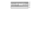
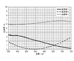
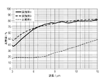
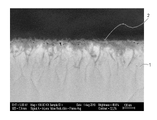
- FIG. It is a measurement result of the reflectance spectrum in the infrared region of the heat storage material obtained in Example 1 and Example 3 and the heat storage material obtained in Comparative Example 1. It is an electron microscope observation figure of the cross section of the heat storage material obtained in Example 3.
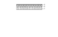
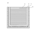
- FIG. It is a schematic diagram which shows the embodiment of the article of this invention. It is a schematic diagram which shows the embodiment of the article of this invention. It is a schematic diagram which shows the embodiment of the article of this invention. It is a schematic diagram which shows the embodiment of the article of this invention.
- one embodiment of the heat storage material for example, a heat storage device or clothing
- the heat storage material includes a metal layer 1 containing a fine uneven shape on the surface of the heat storage member 5, and has a fine uneven shape.
- the height is 100 nm or more and 1000 nm or less.
- a fine concavo-convex shape may be simply referred to as a concavo-convex shape or a fine concavo-convex shape.
- the heat storage member 5 is an element that temporarily stores the heat obtained by the metal layer 1, and is included in the heat storage member 5.
- the heat storage material is not particularly limited as long as it has a large heat capacity, and may be a material containing any one of water, paraffin, oil, fiber, sand, salt, metal, alloy, and metal oxide.
- As an alloy of heat storage material Al—Si alloy is particularly desirable because it has excellent heat storage.
- Magnesium oxide, calcium oxide, or lithium silicate is desirable as the metal oxide of the heat storage material because it has excellent heat storage.
- Aluminum is particularly desirable as a metal for heat storage because it has excellent heat storage.
- a mixed molten salt of sodium nitrate-potassium nitrate-sodium nitrite, a hydroxide-based mixed molten salt, an alkaline carbonate, or an alkaline halide molten salt is particularly desirable because it has excellent heat storage.
- the heat storage member 5 may have a base material (not shown) provided between the metal layer 1 and the heat storage material, and the shape of the base material (not shown) may be a shape according to the purpose of use. Any material can be used, and examples thereof include a flat plate shape, a film shape, and a sheet shape, but the shape is not limited thereto.
- the material of the base material (not shown) include, but are not limited to, metal, glass, ceramics, wood, paper, and resin.
- the resin include polyester, triacetyl cellulose, cellulose acetate, polyethylene terephthalate, polypropylene, polystyrene, and polycarbonate.
- thermoplastic resins such as polymethylmethacrylate, ABS resin, polyphenylene oxide, polyurethane, polyethylene and polyvinyl chloride.
- thermosetting resins such as unsaturated polyester resin, phenol resin, crosslinked polyurethane, crosslinked acrylic resin, and crosslinked saturated polyester resin can be mentioned.
- the metal layer 1 and the heat storage member 5 may be bonded by an adhesive layer 6.
- the adhesive layer 6 may be any layer as long as the metal layer 1 and the heat storage member 5 can be adhered to each other, and examples thereof include a layer made of a cured product of an adhesive resin (for example, an epoxy resin) and double-sided tape.
- FIGS. 2A and 2B show a member (a member shown in FIG. 1C described later) having a transparent metal oxide fine uneven shape 3 and a metal oxide layer 4 on the surface of the metal layer 1.
- the member may include the film shown in FIGS. 1A or 1B described later.
- Highly conductive metals such as aluminum and nickel emit little far infrared rays and have heat storage properties, but do not show absorbance.
- the fine uneven shape due to the sub-wavelength structure smaller than the wavelength of visible light has an antireflection effect, and by continuously changing the space occupancy of the structural part, excellent wavelength band characteristics can be obtained. It is known to exhibit incident angle characteristics. Therefore, when the metal surface is made finely uneven, the reflection on the metal surface is suppressed in a wide wavelength region of visible light, the reflectance in the entire visible light region is lowered, the surface looks black, and the absorbance is exhibited.
- Non-Patent Document 1 has a fine uneven shape obtained by oxidizing the nickel surface on the surface, it emits a large amount of radiation (low reflectance) even in the far infrared region and does not exhibit heat storage.
- the present inventors have found that, in addition to the heat storage property of the metal itself, the specific shape of the fine uneven shape of the metal surface is important for exhibiting the absorbance and the heat storage property, and the present invention has been made.
- the fine uneven shape may be referred to as a fine uneven shape or simply an uneven shape).
- the heat storage material of the present embodiment is provided with a specific fine uneven shape provided on the metal layer on the surface, it is possible to exhibit both absorbance and heat storage.
- the metal layer containing the fine uneven shape of the heat storage material of the present embodiment has a reflectance of 10% or less in the visible light region (550 nm) and a reflectance of 70% or more in the far infrared light region (10 ⁇ m). Is preferable.
- the film formed on the surface of the heat storage member of the heat storage material of the present embodiment has excellent heat storage property, and the heat storage material of the heat storage member in contact with the metal layer having excellent heat storage property can efficiently store heat. ..
- one embodiment of the metal layer 1 is a film provided with the metal layer 1 having a fine uneven shape 2 on the surface.
- a metal having high conductivity is preferable.
- the metal having high conductivity include silver, copper, gold, aluminum, magnesium, tungsten, cobalt, zinc, nickel, chromium and the like, nickel, zinc and chromium are preferable, and nickel is particularly preferable.
- the fine concavo-convex shape 2 provided on the surface of the metal layer 1 is also preferably made of the metal having high conductivity, and more preferably made of the same metal as the metal layer 1.
- the metal layer 1 is preferably a plated layer formed by plating.
- the fine uneven shape object 2 is a fine uneven shape object provided on one surface of the metal layer 1, and the height of the fine uneven shape object 2 is the apex and the concave portion of the convex portion formed on the surface of the metal layer. Refers to the height difference from the bottom point.
- the average height of the fine uneven shape object 2 is 100 nm or more and 1000 nm or less, preferably 100 nm or more and 500 nm or less.
- the height of the fine uneven shape object 2 means the height difference between the peak and the valley bottom defined in "Definition and display of surface roughness" of JIS-B-061, and the maximum roughness (Rmax). Is equivalent to.
- the film having the metal layer 1 of the present embodiment preferably has an average surface roughness Ra'of 1 nm or more and 50 nm or less, which is a surface extension of the center line average roughness Ra.
- the average surface roughness Ra'value (nm) is a three-dimensional extension of the center line average roughness Ra defined in JIS B 0601 applied to the measurement surface, and is "specified from the reference surface". It is expressed as "the average value of the absolute values of the deviations to the surface” and is obtained by the following equation (1).
- Ra' is the average surface roughness (nm)
- S 0 is the area when the measurement surface is ideally flat
- F (X, Y) is the height at the measurement point (X, Y) where the X coordinate is X and the Y coordinate is Y.
- XL to X R are the range of the X coordinate of the measurement surface
- Y B to Y T are the range of the Y coordinate of the measurement surface
- Z 0 is the average height in the measurement surface.
- the film having the metal layer 1 of the present embodiment preferably has a specific surface area Sr of 1.0 or more and 3.0 or less on the surface thereof.
- Equation (2) S 0 is the surface area when the measurement surface is ideally flat, and S is the surface area of the actual measurement surface.
- the surface area of the actual measurement surface is divided into small triangles ⁇ ABC consisting of three data points (A, B, C) closest to each other, and then the area ⁇ S of each small triangle is calculated by the following equation (3).
- the surface area S is obtained by using the vector product, and the sum of the ⁇ S is obtained.
- [ ⁇ S ( ⁇ ABC)] 2 [s (s-AB) (s-BC) (s-CA)] Equation (3)
- the height of the fine uneven shape object 2 can be determined by observing the cross section of the metal layer 1 with a scanning electron microscope or the like. Further, the average surface roughness Ra'and the specific surface area of the surface of the film provided with the metal layer of the heat storage material of the present invention can be determined by observing the surface of the film provided with the metal layer using a scanning probe microscope or the like. Can be done.
- the film provided with the metal layer may have deposits present on the surface of the fine uneven shape object 2 (for example, a metal oxide described later), and the average surface roughness Ra'and the specific surface area of the surface provided with the metal layer of the heat storage material.
- the surface area is a value including deposits.
- a membrane provided with a metal layer may be referred to as an absorption heat storage membrane.
- the fine uneven shape of the transparent metal oxide which is in close contact with the fine uneven shape object 2. 3 may be provided.
- the transparent metal oxide layer 4 covering the surface of the fine uneven shape 3 of the metal oxide that is not in contact with the fine uneven shape 2 is used. May be further provided.
- close contact means that the metal oxide constituting the fine concavo-convex shape 3 of the metal oxide fills the space surrounded by the fine concavo-convex shape 2 and reaches the metal layer 1.
- the average surface roughness Ra'and the specific surface area of the surface are the average surface roughness obtained by expanding the center line average roughness Ra. It is preferable that Ra'is 1 nm or more and 50 nm or less. Further, it is preferable that the specific surface area Sr of the surface of the fine uneven shape object 2 is 1.0 or more and 3.0 or less.
- the material of the fine uneven shape 3 of the metal oxide is not particularly limited, but it is preferable that the main component is alumina, and it is more preferable that the plate-like crystal containing alumina as the main component is contained.
- the plate-like crystals containing alumina as a main component are formed of plate-like crystals containing an oxide or hydroxide of aluminum or a hydrate thereof as a main component, and a particularly preferable crystal is boehmite.
- the plate-like crystal containing alumina as a main component may be a plate-like crystal composed of only alumina, or a plate-like crystal containing a trace amount of zirconium, silicon, titanium, zinc, etc. in the plate-like crystal of alumina. You may.
- the fine uneven shape 3 of the metal oxide By providing the fine uneven shape 3 of the metal oxide, the fine uneven shape 2 can be protected. Further, when the fine concavo-convex shape 3 of the metal oxide is a plate-like structure of a plate-like crystal containing alumina as a main component, the plate-like crystal containing alumina as a main component is in a direction perpendicular to the plane direction of the metal layer 1. It is preferable that the space occupancy rate is continuously changing.
- the material of the metal oxide layer 4 is not particularly limited, but it is preferable to contain an amorphous gel of alumina.
- the metal oxide layer 4 increases the hardness of the surface of the film of the present invention, while lowering the absorbance. Therefore, the thickness of the metal oxide layer 4 may be appropriately determined so as to satisfy the required hardness and absorbance.
- the fine uneven shape 2, the fine uneven shape 3, and the aluminum element, silicon element, etc. in the metal oxide layer 4 are energy for surface and cross-sectional observation by a scanning electron microscope (SEM) or a transmission electron microscope (TEM). It can be detected by distributed X-ray analysis (EDX). Further, it can be detected by measurement of X-ray electron spectroscopy (XPS) or the like.
- SEM scanning electron microscope
- TEM transmission electron microscope
- EDX distributed X-ray analysis
- XPS X-ray electron spectroscopy
- the fine uneven shape 2 the fine uneven shape 3, or the metal oxide layer 4
- the ratio changes in the direction perpendicular to the surface direction of the metal layer 1. That is, the proportion of metal oxides such as aluminum elements becomes relatively low from the surface (metal oxide layer 4) toward the inside (metal layer 1), and the metal elements constituting the metal layer 1 and the fine uneven shape object 2 are formed. The proportion of metal elements becomes high, and finally only metal elements are detected.
- the method for producing the heat storage material of the present embodiment includes a first step of forming the fine uneven shape of the metal oxide and a second step of forming the metal layer 1 on the fine uneven shape of the metal oxide. Further, the step of adhering the heat storage member 5 to the surface of the metal layer 1 opposite to the surface in contact with the fine uneven shape 3 of the metal oxide is included.
- First step A step of producing a fine uneven shape of a metal oxide
- a fine uneven shape of the metal oxide used as a mold is formed.
- the material of the metal oxide having a fine uneven shape is not particularly limited, but it is preferable to use alumina as a main component.
- the fine uneven shape can be formed by a known vapor phase method such as chemical vapor deposition (CVD) or physical vapor deposition (PVD), or a sol-gel liquid phase method. From these methods, it is possible to provide a fine concavo-convex shape of a metal oxide containing a plate-like crystal containing alumina as a main component. Above all, a method of treating a film containing aluminum with warm water to grow alumina plate-like crystals is preferable.
- the film containing aluminum examples include an alumina gel film formed by applying a sol-gel coating liquid containing an aluminum compound, and a film containing metallic aluminum formed by dry film formation such as vacuum deposition or a sputtering method. It is preferable to use an alumina gel film to form the fine uneven shape of the metal oxide because it is easy to adjust the reactivity and the height of the fine uneven shape of the metal oxide.
- an aluminum compound such as aluminum alkoxide, an aluminum halide, or an aluminum salt can be used. From the viewpoint of film forming property, it is preferable to use aluminum alkoxide.
- the aluminum compound examples include aluminum alkoxides such as aluminum ethoxyde, aluminum isopropoxide, aluminum-n-butoxide, aluminum-sec-butoxide, and aluminum-tert-butoxide. Further, these oligomers, halides of aluminum such as aluminum chloride, aluminum acetylacetonate of aluminum salts such as aluminum nitrate, aluminum acetate, aluminum phosphate and aluminum sulfate, aluminum acetylacetonate, aluminum hydroxide and the like can be mentioned.
- aluminum alkoxides such as aluminum ethoxyde, aluminum isopropoxide, aluminum-n-butoxide, aluminum-sec-butoxide, and aluminum-tert-butoxide.
- these oligomers halides of aluminum such as aluminum chloride, aluminum acetylacetonate of aluminum salts such as aluminum nitrate, aluminum acetate, aluminum phosphate and aluminum sulfate, aluminum acetylacetonate, aluminum hydroxide and the like
- the alumina gel film may contain other compounds.
- Other compounds include, for example, zirconium, silicon, titanium, zinc alkoxides, halides, salts and combinations thereof.
- the height of the fine uneven shape of the metal oxide to be formed can be increased as compared with the case where these are not contained.
- the alumina gel film is formed on the base substrate by applying a sol-gel coating liquid containing an aluminum compound.
- the sol-gel coating solution is prepared by dissolving an aluminum compound in an organic solvent.
- the amount of the organic solvent with respect to the aluminum compound is preferably about 20 times the molar ratio.
- alcohol carboxylic acid, aliphatic hydrocarbon, alicyclic hydrocarbon, aromatic hydrocarbon, ester, ketone, ether, or a mixed solvent thereof
- examples of the alcohol include methanol, ethanol, 2-propanol, butanol, 2-methoxyethanol, 2-ethoxyethanol, 1-methoxy-2-propanol and 1-ethoxy-2-propanol.
- 1-propanol-2-propanol, 4-methyl-2-pentanol, 2-ethylbutanol, 3-methoxy-3-methylbutanol, ethylene glycol, diethylene glycol, glycerin and the like can be mentioned.
- Examples of the carboxylic acid include n-butyric acid, ⁇ -methylbutyric acid, iso-valeric acid, 2-ethylbutyric acid, 2,2-dimethylbutyric acid, 3,3-dimethylbutyric acid, 2,3-dimethylbutyric acid, and 3-methyl.
- Examples include pentanoic acid.
- Examples of the aliphatic hydrocarbon or the alicyclic hydrocarbon include n-hexane, n-octane, cyclohexane, cyclopentane, cyclooctane and the like.
- Examples of aromatic hydrocarbons include toluene, xylene, ethylbenzene and the like.
- Examples of the esters include ethyl formate, ethyl acetate, n-butyl acetate, ethylene glycol monomethyl ether acetate, ethylene glycol monoethyl ether acetate, ethylene glycol monobutyl ether acetate and the like.
- ketones include acetone, methyl ethyl ketone, methyl isobutyl ketone, cyclohexanone and the like.
- ethers include dimethoxyethane, tetrahydrofuran, dioxane, diisopropyl ether and the like. Above all, it is preferable to use alcohol from the viewpoint of the stability of the sol-gel coating liquid.
- aluminum alkoxide When aluminum alkoxide is used as the aluminum compound, it is highly reactive with water, so the aluminum alkoxide may be rapidly hydrolyzed by the addition of water or water in the air, resulting in cloudiness and precipitation of the sol-gel coating liquid. In order to prevent these, it is preferable to add a stabilizer to the sol-gel coating liquid to stabilize it.
- a stabilizer As the stabilizer, ⁇ -diketone compounds, ⁇ -ketoester compounds, alkanolamines and the like can be used.
- Examples of ⁇ -diketone compounds include acetylacetone, trifluoroacetylacetone, hexafluoroacetylacetone, benzoylacetone, 3-methyl-2,4-pentandione, 3-ethyl-2,4-pentandione and the like.
- Examples of ⁇ -ketoester compounds include methyl acetoacetate, ethyl acetoacetate, butyl acetoacetate, hexyl acetoacetic acid, allyl acetoacetic acid, and benzyl acetoacetate.
- acetoacetic acid-iso-propyl acetoacetic acid-2-methoxyethyl
- acetoacetic acid-sec-butyl acetoacetic acid-tert-butyl
- acetoacetic acid-iso-butyl examples include monoethanolamine, diethanolamine, triethanolamine and the like.
- the amount of the stabilizer with respect to the aluminum alkoxide is preferably about 1 time in molar ratio.
- a catalyst may be used to promote the hydrolysis reaction of aluminum alkoxide.
- the catalyst include nitric acid, hydrochloric acid, sulfuric acid, phosphoric acid, acetic acid, ammonia and the like.
- a water-soluble organic polymer compound can be added to the alumina gel film as needed.
- the water-soluble organic polymer compound is easily eluted from the alumina gel film by immersion in warm water, which increases the reaction surface area between the aluminum compound and hot water and enables the formation of fine uneven shapes at low temperature and in a short time.
- by changing the type and molecular weight of the organic polymer to be added it is possible to control the height of the formed fine uneven shape.
- the organic polymer polyether glycols such as polyethylene glycol and polypropylene glycol are preferable because they are easily eluted from the alumina gel film by immersion in warm water.
- the amount of polyether glycols with respect to the weight of the aluminum compound in the alumina gel film is preferably in the range of 0.1 to 10 times by weight.
- the sol-gel coating solution is prepared by dissolving or suspending the aluminum compound and, if necessary, other compounds, stabilizers, and water-soluble organic polymer compounds in an organic solvent.
- This sol-gel coating liquid is applied onto the base substrate 8 and dried to form an alumina gel film as a film 7 containing aluminum.
- a film containing metallic aluminum as the film 7 containing aluminum is formed on the base substrate 8 by dry film formation such as vacuum deposition or sputtering.
- the material of the base base material 8 is not particularly limited, and various materials such as glass, plastic, and metal can be used.
- the atmosphere for coating is an inert gas atmosphere such as dry air or dry nitrogen.
- the relative humidity in the dry atmosphere is preferably 30% or less.
- known coating means such as a dipping method, a spin coating method, a spray method, a printing method, a flow coating method, and a combination thereof can be appropriately adopted.
- the film thickness can be controlled by changing the pulling speed in the dipping method, the substrate rotation speed in the spin coating method, and the like, and by changing the concentration of the sol-gel coating liquid. Drying may be performed at room temperature for about 30 minutes.
- the suitable film thickness of the film 7 containing aluminum is 100 nm or more and 600 nm or less, preferably 100 nm or more and 300 nm or less, and more preferably 100 nm or more and 200 nm or less.
- the film 7 containing aluminum is immersed in warm water to form a fine uneven shape of alumina.
- the surface layer of the alumina gel film undergoes a gluing action or the like, and some components are eluted.
- plate-like crystals containing alumina as a main component are deposited and grown on the surface layer of the alumina gel film, so that the fine uneven shape 3 of the metal oxide is formed. ..
- the fine uneven shape of the metal oxide 3 is the same as when the alumina gel film is used. Is formed. Therefore, when the material of the base base material 8 mainly contains aluminum or alumina, it is possible to omit the film formation of the film 7 containing aluminum on the base base material 8.
- the temperature of the hot water is preferably 40 ° C. or higher and lower than 100 ° C.
- the immersion treatment time is preferably about 5 minutes to 24 hours.
- the plate-like crystals of alumina are crystallized by using the difference in the solubility of each component in warm water. Therefore, unlike the dipping treatment of the alumina gel film containing a single alumina component, the size of the plate-like crystal can be controlled over a wide range by changing the composition of the inorganic component. Further, the height of the fine concavo-convex shape 3 of alumina can be adjusted by adjusting the film thickness of the film 7 containing aluminum.
- the average height of the fine uneven shape 3 of the metal oxide is preferably 100 nm or more and 1000 nm or less, and more preferably 100 nm or more and 500 nm or less. As a result, it becomes possible to control the fine irregularities formed by the plate-like crystals over a wide range.
- a metal layer is formed on the fine uneven shape of the metal oxide, and a fine uneven shape to which the fine uneven shape is transferred is formed on the metal layer.
- a step of forming the metal layer 1 on the fine uneven shape 3 of the metal oxide will be described below.
- a metal plating treatment is preferable, and an electroless plating treatment is further preferable.
- an aqueous solution in which a palladium compound such as palladium chloride, a gold compound such as gold chloride, a silver compound such as silver chloride, and a tin compound such as tin chloride is dissolved is applied to the fine uneven shape 3 of the metal oxide.
- activation is performed.
- the activation may be carried out by immersing the fine uneven shape 3 of the metal oxide together with the base base material 8 in an aqueous solution in which the palladium compound is dissolved. Then, the metal layer 1 is deposited on the fine uneven shape 3 of the metal oxide using the electroless plating solution.
- the metal ion in the electroless plating solution corresponds to the metal layer of the present invention, and an electroless plating solution containing nickel ions, chromium ions, and zinc ions is preferable, and a nickel plating solution containing nickel ions is particularly preferable.
- the nickel plating solution may contain a phosphorus component and a boron component in addition to the nickel component. Examples of commercially available nickel plating solutions include the Top Nicolon series of Okuno Pharmaceutical Industry Co., Ltd.
- the temperature of the plating solution in the electroless plating treatment is preferably 30 ° C. or higher and 98 ° C. or lower, more preferably 50 ° C. or higher and 90 ° C. or lower.
- the time for performing the electroless plating treatment can be adjusted according to the thickness of the metal layer to be formed, and is usually 30 seconds to 1 hour.
- the metal layer 1 is formed so as to fill the gaps of the fine concavo-convex shape, and the metal layer 1 including the fine concavo-convex shape 2 to which the fine concavo-convex shape 3 of the metal oxide is transferred is formed.
- the metal layer 1 has an uneven shape corresponding to the fine uneven shape 3 of the metal oxide.
- the thickness of the metal layer 1 including the fine concavo-convex shape 2 is 200 nm or more and 15,000 nm or less.
- the average height of the fine concavo-convex shape 2 corresponds to the average height of the fine concavo-convex shape 3 of the metal oxide, and is 100 nm or more and 1000 nm or less.
- the absorption heat storage film of the present invention exhibits excellent absorption heat storage characteristics.
- electroplating may be performed on the surface of the metal layer 1 opposite to the surface on which the fine concavo-convex shape 2 is provided. ..
- a known electroplating solution can be used for the electroplating treatment, and for example, an electroplating solution containing nickel ion, iron ion, copper ion or the like can be used as the metal ion.
- the electroplating treatment is performed using the same metal as the metal of the metal layer 1, the thickness of the metal layer can be increased by the electroplating treatment.
- the electroplating treatment is performed using a metal different from the metal of the metal layer 1, the metal layer provided by the electroplating treatment becomes the heat storage member 5.
- the thickness of the metal layer 1 can be made a desired thickness by adjusting the liquid temperature, the current density, and the plating time of the electroplating liquid.
- an aqueous solution containing an acid or the like may be used to activate the surface of the metal layer 1 opposite to the surface on which the fine concavo-convex shape 2 is provided.
- a step of removing foreign matters in the electroplating solution may be provided.
- the heat storage member 5 is adhered to the surface opposite to the surface of the metal layer 1 obtained above on which the fine uneven shape object 2 is provided.
- the shape and material of the heat storage member 5 those described above can be used.
- the material of the base material of the heat storage member 5 is metal
- the metal to be the base material of the heat storage member 5 may be further laminated on the surface opposite to the surface of the metal layer 1 on which the fine concavo-convex shape 2 is provided. ..
- the metal may be laminated by the above-mentioned electroplating treatment, or may be laminated by physical vapor deposition such as sputtering.
- the heat storage member is cured by depositing the resin to be the heat storage member 5 on the surface opposite to the fine uneven shape 3 of the metal oxide of the metal layer 1. May be provided.
- the heat storage member 5 may be adhered to the metal layer 1 by the adhesive layer 6.
- the adhesive material used for the adhesive layer 6 is not particularly limited, and may be any material as long as the heat storage member 5 and the metal layer 1 are firmly adhered to each other.
- FIGS. 3E to 3H the etching step will be described in detail using the heat storage material provided with the heat storage member 5 and the adhesive layer 6 as an example.
- a heat storage material may be attached to the base material to form a heat storage member.
- the heat storage material may be attached to the base material to form the heat storage member. Note that FIG. 3E shows the heat storage material shown in FIG. 3D turned upside down.
- the base base material 8 is removed as shown in FIG. 3F.
- the heat storage material after removal of the base base material 8 is provided with a film 7 containing aluminum on its surface.
- the film 7 containing aluminum is a film containing metallic aluminum
- visible light is reflected by the metallic aluminum, so that it is necessary to further remove the film containing metallic aluminum by etching as shown in FIG. 3G.
- the film 7 containing aluminum is an alumina gel film
- the alumina gel film is the metal oxide layer 4 of the heat storage member. Therefore, the alumina gel film may be removed by etching so as to satisfy the required surface hardness and absorbance.
- the etching method wet etching in which the film 7 containing aluminum is dissolved by using an acid or alkaline solution is preferable.
- the acid include hydrochloric acid, nitric acid, sulfuric acid and the like.
- the alkali include sodium hydroxide, potassium hydroxide and the like. From the viewpoint of work efficiency, an etching method using an alkaline solution is more preferable.
- the etching concentration is preferably in the range of several% to several tens of percent, and the etching time is preferably in the range of several hours to several days.
- the fine uneven shape 3 of the metal oxide may also be removed by etching.
- the heat storage member in which the metal layer 1 including the fine uneven shape 2 on the outermost surface is adhered to the heat storage member 5 via the adhesive layer 6 realizes particularly excellent absorption.
- Residual metal oxides such as alumina after etching can be detected by measuring EDX or XPS when observing the surface or cross section with SEM or TEM.
- the degree of etching treatment may be adjusted according to the balance between the absorption heat storage performance and the surface hardness of the desired heat storage member or metal layer. Further, the etching step of this step may be performed before the bonding step of the heat storage member 5, which is the third step, and then the heat storage member 5 may be bonded.
- the heat storage material of the present embodiment includes the metal layer 1 including the fine uneven shape object 2, the reflectance in the visible light region is low because it absorbs visible light, and the radiation of far infrared rays is small, so that it is far.
- the reflectance in the infrared region is high, and excellent absorption and heat storage characteristics can be realized.
- a film (absorbent heat storage film) containing the metal layer 1 of the present embodiment can be provided on the surface of various members.
- the absorption heat storage film of the present embodiment may be used as a heat storage decorative film.
- the absorption heat storage film of the present invention can be provided as a heat storage decorative film on the surface of vehicle interiors, mobile devices, electronic devices such as home appliances, sunshades, and tent supplies.
- Various adhesives can be used when the absorption heat storage film of the present invention is provided on the surface of a member or a heat storage material.
- the absorption heat storage film of the present invention can be provided on the surface of the member and the heat storage material according to the purpose of use, and the surface of the member and the heat storage material is not limited to a smooth surface, and a two-dimensional or three-dimensional curved surface can be formed. It may have.
- the heat storage material of this embodiment has excellent absorption and heat storage properties, it can be used for various articles. For example, since the energy of sunlight can be efficiently used, it can be used in a solar hot water supply system. When used in a solar hot water supply system, a steam generation pipe (not shown) is passed through the heat storage member 5. During times when sunlight cannot be used, such as at night, an unheated heat medium can be passed through the steam generation pipe, and the heat medium can be heated by the heat storage material contained in the heat storage member 5 whose temperature has risen.
- the heat storage material of this embodiment has excellent heat storage properties, the energy of sunlight can be efficiently used, so that it can be used in a solar thermal power generation system.
- a steam generation pipe (not shown) is passed through the heat storage member 5.
- an unheated heat medium is passed through the steam generation pipe, and the heat medium is heated by the heat storage material contained in the heat storage member 5 whose temperature has risen.
- the heated heat medium can generate electricity by generating steam in a steam generator (not shown) and operating a steam turbine (not shown).
- the heat storage material of this embodiment has excellent heat storage properties, the energy of sunlight can be efficiently used, so that it can be used for an artificial satellite. Since the temperature difference between artificial satellites is large on the surface exposed to sunlight and the surface not exposed to sunlight, it is desirable because the temperature difference can be reduced by storing heat when it is exposed to sunlight and dissipating heat when it is not exposed to sunlight. For example, by using the device having the heat storage material and the heat radiation material of the present embodiment, the temperature difference can be reduced as follows. When the artificial satellite is at a low temperature, heat is stored by exposing the heat storage material to the outside by means for exposing the heat storage material of the present embodiment to the outside, and the decrease in temperature is suppressed.
- the means for exposing the heat storage material to the outside and the means for exposing the heat radiating material to the outside may be the same or different means. By using it in this way, the power for the heat insulating heater can be significantly reduced.
- FIG. 8 shows a solar collector, which is an example of the article 20 containing the heat storage material.
- water can be used as the heat storage member 5.
- the heat storage member 5 (water) is housed in the container 9.
- a metal layer 1 is provided on the outside of the container 9.
- the container 5 is located between the heat storage member 5 and the metal layer 1.
- a heat insulating material 10 is provided on the outside of the metal layer 1.
- the metal layer 1 is located between the heat insulating material 10 and the heat storage member 5.
- the heat insulating material 10 for example, xerogel can be used.
- solar heat can be stored in the water (heat storage member 5) contained in the container 9.
- FIG. 9A shows an artificial satellite, which is an example of 20 including a heat storage material.
- the article 20 as an artificial satellite includes a heat control unit 11, a control unit 12, a power generation unit 13, and a communication unit 14.
- 9B shows a cross-sectional view taken along the line AA'of the heat control unit 11 in FIG. 9A.
- a metal layer 1 is provided on the heat storage member 5.
- the metal layer 1 is adhered to the container 5 accommodating the heat storage member 5 via an adhesive layer 6 located between the metal layer 1 and the heat storage member 5.
- paraffin can be used as the heat storage member 5.
- the heat control unit 11 can store heat with sunlight.
- a heat radiating material can be provided on the article 20 such as an artificial satellite.
- a predetermined portion of the article 20 for example, the control unit 12
- heat can be stored in the heat storage material of the heat control unit 11.
- the predetermined portion for example, the control unit 12
- the predetermined temperature for example, the control unit 12
- the predetermined temperature for example, the control unit 12
- the predetermined temperature for example, the control unit 12
- the article 20 as an artificial satellite can perform at least one of deformation and displacement so that such heat storage and heat dissipation can be switched.
- the shape in which the heat storage material faces the outside of the artificial satellite (for example, the side opposite to the control unit 12) and the heat radiating material faces the inside of the artificial satellite (for example, the side of the control unit 12) is the heat storage shape.
- the shape in which the heat radiating material faces the outside of the artificial satellite (for example, the side opposite to the control unit 12) and the heat storage material faces the inside of the artificial satellite (for example, the side of the control unit 12) is the heat radiating shape. Then, the artificial satellite can be deformed so as to switch between the heat storage shape and the heat dissipation shape.
- the artificial satellite takes a posture in which the heat storage material faces the heat source around the artificial satellite (for example, the sun) and the heat radiating material faces the opposite side (for example, the earth) from the heat source around the artificial satellite. It can also be displaced.
- the heat storage material of this embodiment can be used for hybrid type photovoltaic power generation in combination with a photovoltaic power generation cell.
- Photovoltaic cells can use silicon, organic semiconductors, organic-inorganic perovskite semiconductors, and the like.
- the transmitted light of the solar power generation cell is absorbed by the heat storage material, and by suppressing the radiation, heat is efficiently stored and the solar heat is stored. It can be used.
- the translucent heat insulating material for example, airgel or xerogel can be used.
- FIG. 10 shows a solar panel, which is an example of an article 20 containing a heat storage material, in FIG. 8.
- oil can be used as the heat storage member 5.
- the heat storage member 5 (oil) is housed in the container 9.
- a metal layer 1 is provided on the outside of the container 9.
- the container 5 is located between the heat storage member 5 and the metal layer 1.
- the metal layer 1 is adhered to the heat storage member 5 via the adhesive layer 6, and the adhesive layer 6 is located between the container 5 and the metal layer 1.
- a photovoltaic power generation cell 15 is provided on the outside of the metal layer 1. Silicon can be used for the photovoltaic power generation cell 15.
- the metal layer 1 is located between the photovoltaic power generation cell 15 and the heat storage member 5.
- a heat insulating material 10 is provided on the outside of the photovoltaic power generation cell 15.
- the photovoltaic power generation cell 15 is located between the heat insulating material 10 and the metal layer 1.
- a photovoltaic power generation cell 15 is provided between the heat storage member 5 and the heat storage material having the metal layer 1 provided on the heat storage member 5 and the heat insulating material 10.
- the heat insulating material 10 for example, vacuum-filled glass can be used.
- a hybrid type photovoltaic power generation system can be configured, and solar power can be generated and stored.
- a system that uses the heat energy of the sun can be called a solar heat utilization system.
- the solar heat utilization system is the above-mentioned solar hot water supply system or solar thermal power generation system.
- the solar heat utilization system includes the heat storage material of the present embodiment, and the solar heat utilization system includes an article provided with the heat storage material.
- the article provided with the heat storage material may be provided with a heat insulating material or a heat radiating material in addition to the heat storage material.
- the heat insulating material and the heat radiating material in the article provided with the heat storage material can be fixed to the heat storage material.
- the solar heat utilization system may include other articles such as piping, a heat medium, and a steam turbine, in addition to the articles provided with the heat storage material. Other articles in the solar heat utilization system need not be fixed to the article provided with the heat storage material.
- a system that utilizes the light energy of the sun can be called a solar utilization system.
- the solar utilization system is the above-mentioned solar power generation system or solar lighting system.
- the solar utilization system includes the heat storage material of the present embodiment, and the solar utilization system includes an article provided with the heat storage material.
- the article provided with the heat storage material may be provided with a heat insulating material or a heat radiating material in addition to the heat storage material.
- the heat insulating material and the heat radiating material in the article provided with the heat storage material can be fixed to the heat storage material.
- the solar utilization system may include other articles such as wiring, a battery, and a power conditioner, in addition to the article provided with the heat storage material. Other articles in the solar heat utilization system need not be fixed to the article provided with the heat storage material.
- a solar heat utilization system or a solar utilization system can also be called a solar system.
- Solar systems can include solar collectors, solar pots, and solar panels.
- a lens reflectance measuring device (trade name: USPM-RU III, manufactured by Olympus Corporation) was used for the reflectance spectrum measurement in the visible light region of the examples.
- a Fourier transform infrared spectrophotometer (FT / IR-6600, manufactured by Nippon Spectroscopy Co., Ltd.) was used for the reflectance spectrum measurement in the infrared region of the example.
- Example 1 Aluminum-sec-butoxide (hereinafter, also referred to as “Al (O-sec-Bu) 3 ”) and ethyl acetoacetate (hereinafter, also referred to as “EtOAc Ac”) are also referred to as 2-propanol (hereinafter, also referred to as “IPA”). ), And the mixture was stirred at room temperature for about 3 hours to prepare an alumina sol solution.
- a 0.01 M dilute hydrochloric acid aqueous solution was added to the alumina sol solution so that the hydrochloric acid additive was doubled in terms of molar ratio with respect to Al (O-sec-Bu) 3 , and the mixture was refluxed for about 6 hours to form a sol-gel coating.
- a solution was prepared.
- a sol-gel coating liquid was applied onto a quartz glass substrate as a base material by a spin coating method to form a coating film. Then, the coating film was heat-treated at 100 ° C. for 1 hour to obtain a transparent alumina gel film. Next, the alumina gel film was immersed in warm water at 80 ° C. for 30 minutes and then dried at 100 ° C. for 10 minutes to form an alumina layer having a fine uneven shape.
- a palladium chloride aqueous solution was applied on an alumina layer having a fine uneven shape by a spin coating method, and then dried at 100 ° C. Then, it was immersed in a nickel-phosphorus plating solution (phosphorus content of about 10 wt%) set at 80 ° C. for 1 minute to form a fine uneven shape and a nickel layer as a metal layer.
- a nickel-phosphorus plating solution phosphorus content of about 10 wt% set at 80 ° C. for 1 minute to form a fine uneven shape and a nickel layer as a metal layer.
- An epoxy resin to be an adhesive layer was applied and cured on the surface of the obtained metal layer opposite to the alumina layer having a fine uneven shape, and a PET film was adhered as a base material of a heat storage member via the adhesive layer. After that, it was peeled off from the quartz glass substrate. The base material was attached to a quartz cell containing water as a heat storage material.
- Example 1 a nickel layer formed on an alumina layer having a fine uneven shape is cut out with a dicing saw and then sliced in the cross-sectional direction by a focus ion beam (FIB) method to form a cross section.
- FIB focus ion beam
- the cross-sectional observation was performed using a scanning transmission electron microscope (trade name: HD-2300, manufactured by Hitachi High-Technologies Corporation). From the observation image shown in FIG. 4, the nickel fine uneven shape 2 is formed so as to fill the inside of the alumina plate-like crystal which is the fine uneven shape 3 of the metal oxide formed from the alumina gel film on the base base material 8.
- the average height of the obtained fine concavo-convex shape 2 of Example 1 was 323 nm, the average height of the fine concavo-convex shape 3 was 255 nm, and the film thickness of the film 7 containing aluminum was 68 nm.
- the average surface roughness Ra'of the surface was 1.0 nm, and the specific surface area was 1.0.
- the reflectance spectrum in the visible light region and the reflectance spectrum in the infrared region of Example 1 were measured.
- a lens reflectivity measuring device (trade name: USPM-RU III, manufactured by Olympus Co., Ltd.) is used for the reflectance spectrum measurement, and a Fourier transform infrared spectrophotometer (trade name: FT) is used for the infrared region reflectance spectrum measurement.
- FT Fourier transform infrared spectrophotometer
- Table 1 shows the reflectances in the visible light and infrared regions obtained by the reflectance spectrum measurements in the visible light region and the infrared region of Example 1. From FIG. 5, it can be said that Example 1 has excellent absorbance because the reflectance in the visible light region is low.
- Example 1 has excellent heat storage property because the reflectance increases toward the long wavelength side in the mid-infrared and far-infrared regions.
- Comparative Example 1 was inferior to the sample of Example 1, but had low reflectance in the visible light to near infrared region.
- the sample of Comparative Example 1 was inferior to that of Example 1 in the reflectance in the mid-infrared region and the far-infrared region.
- Example 2 In the same manner as in Example 1, an alumina sol solution was prepared and used by a spin coating method to be applied onto a quartz glass substrate as a base substrate to form a coating film. Then, the coating film was heat-treated at 100 ° C. for 1 hour to obtain a transparent alumina gel film. Next, the alumina gel film was immersed in warm water at 80 ° C. for 30 minutes and then dried at 100 ° C. for 10 minutes to form an alumina layer having a fine uneven shape.
- a palladium chloride aqueous solution was applied on an alumina layer having a fine uneven shape by a spin coating method, and then dried at room temperature. Then, it was immersed in a nickel-phosphorus plating solution (phosphorus content of about 10 wt%) set at 80 ° C. for 20 minutes to form a fine uneven shape and a nickel layer as a metal layer.
- a nickel-phosphorus plating solution phosphorus content of about 10 wt% set at 80 ° C. for 20 minutes to form a fine uneven shape and a nickel layer as a metal layer.
- the total film thickness obtained was about 10 ⁇ m.
- the average height of the fine concavo-convex shape of the obtained film was 303 nm, the average height of the fine concavo-convex shape was 233 nm, and the film thickness of the film containing aluminum was 70 nm. Further, the average surface roughness Ra'of the film was 1.0 nm, and the specific surface area was 1.0.
- the film was manufactured by changing the number of laminated gel films and the etching conditions.
- Example 3 A film was produced in the same manner as in Example 2, and the film peeled from the quartz glass substrate was etched with a 3M aqueous sodium hydroxide solution at room temperature for 50 hours as an etching step to produce the film.
- the average height of the fine uneven shape of the obtained film was 251 nm
- the average height of the fine uneven shape was 213 nm
- the average surface roughness Ra' was 5.0 nm
- the specific surface area was 1.1.
- the result of the reflectance spectrum measurement in the visible light region is shown in FIG. 5, and the result of the reflectance spectrum measurement in the infrared region is shown in FIG.
- a cross section was obtained by the FIB method, and the cross section was observed by SEM.
- the cross-sectional observation was performed using a scanning electron microscope (trade name: ULTRA55, manufactured by Carl Zeiss). From the observation image shown in FIG. 7, the fine uneven shape of nickel 2 was formed on the nickel layer which is the metal layer 1, and a small amount of alumina remained on the fine uneven shape 2.
- the proportion of Al element was relatively low from the surface toward the inside in the film thickness direction of the cross section, while the proportion of Ni element was high.
- Example 4 A film was produced in the same manner as in Example 3 except that the etching process was performed at room temperature for 47 hours using a 7.5 M aqueous sodium hydroxide solution.
- the average height of the fine uneven shape of the obtained film was 235 nm, the average surface roughness Ra'was 18 nm, and the specific surface area was 1.4.
- Example 5 A film was produced in the same manner as in Example 3 except that a nickel-phosphorus plating solution (phosphorus content of about 1 to 2 wt%) was used as the plating solution.
- the average height of the fine uneven shape of the obtained film was 272 nm, the average surface roughness Ra'was 3.8 nm, and the specific surface area was 1.1.
- Example 6 The alumina sol solution shown in Example 2 was prepared and applied onto a quartz glass substrate as a base substrate by a spin coating method to form a coating film. After that, the coating film is heat-treated at 100 ° C. for 1 hour, and the same film coating and drying process is repeated again to increase the number of alumina gel films to two, and to form a transparent alumina gel film as a film containing aluminum. Obtained. After that, a film was produced in the same manner as in Example 2. The average height of the fine uneven shape of the obtained film was 371 nm, the average height of the fine uneven shape was 306 nm, the average surface roughness Ra'was 1.1 nm, and the specific surface area was 1.0.
- Example 7 After peeling the metal film provided with the alumina layer from the quartz glass substrate, the film was manufactured in the same manner as in Example 6 except that the metal film provided with the alumina layer was etched with a 3M sodium hydroxide aqueous solution at room temperature for 50 hours as an etching step.
- the average height of the fine uneven shape of the obtained film was 315 nm, the average surface roughness Ra'was 10 nm, and the specific surface area was 1.2.
- Example 8 A film was produced in the same manner as in Example 7 except that the etching step was performed by etching at room temperature for 50 hours using a 7.5 M aqueous sodium hydroxide solution.
- the average height of the fine uneven shape of the obtained film was 303 nm, the average surface roughness Ra'was 27 nm, and the specific surface area was 1.7.
- Example 9 A film was produced in the same manner as in Example 2 except that the number of laminated alumina gel films was three.
- the average height of the fine uneven shape of the obtained film was 419 nm
- the average height of the fine uneven shape was 374 nm
- the average surface roughness Ra' was 1.2 nm
- the specific surface area was 1.0.
- Example 10 After peeling the metal film provided with the alumina layer from the quartz glass substrate, the film was manufactured in the same manner as in Example 9 except that the metal film provided with the alumina layer was etched with a 3M sodium hydroxide aqueous solution at room temperature for 50 hours in the etching step.
- the average height of the fine uneven shape of the obtained film was 354 nm, the average surface roughness Ra'was 16 nm, and the specific surface area was 1.3.
- Example 11 A film was produced in the same manner as in Example 10 except that the etching process was performed at room temperature for 45 hours using a 6 M aqueous sodium hydroxide solution.
- the average height of the fine uneven shape of the obtained film was 346 nm, the average surface roughness Ra'was 35 nm, and the specific surface area was 2.1.
- Table 1 shows the reflectances of the visible light region and the infrared region obtained by the reflection spectrum measurement of the visible light region and the infrared region of the samples manufactured in Examples 1 to 11 and Comparative Example 1.
- Example 12 A sample was produced by putting 40 ml of water in a quartz cell of 10 mm ⁇ 10 mm ⁇ 45 mm in the same manner as in Example 1. The sample left at room temperature (25 ° C.) was irradiated with a 150 W halogen lamp at a distance of 10 mm. After the irradiation, the irradiation of the halogen lamp was stopped and the mixture was left for 10 minutes, and then the temperature of the water was measured with a thermocouple. The results are shown in Table 2.
- Comparative Example 2 It was evaluated in the same manner as the sample produced in the same manner as in Example 12 with the absorbent material of Comparative Example 1. The results are shown in Table 2.
- Example 12 It was found that heat is stored more efficiently in Example 12 because the temperature raised by irradiating the same energy is higher than that in Comparative Example 2.
- the heat storage material of the present invention is excellent in both absorbency and heat storage.
- the present invention it is possible to provide an absorbent heat storage film and a heat storage member that absorb visible light and near infrared rays (low reflectance) and emit small far infrared rays (high reflectance), which are normally incompatible.
- the absorption heat storage film and the heat storage member of the present invention can be used as a heat storage member for space-related equipment such as artificial satellites and solar thermal power generation, and can also be used as an exterior film, a solar collector, and the like.
Abstract
According to the present invention, a light-absorbing and heat-storing film is characterized by comprising a metal layer including a protrusion-and-recess-shaped object, wherein the average height of the protrusion-and-recess-shaped object is 100 nm to 1,000 nm.
Description
本発明は、蓄熱材、およびその製造方法に関する。
The present invention relates to a heat storage material and a method for producing the same.
近年、太陽熱発電や宇宙機器において、吸光蓄熱材料の利用が拡大している。吸光蓄熱材料としては、可視域の電磁波(光)を吸収し、赤外域の電磁波(光)の放射が小さいことが望ましい。吸光材料としては、黒色無電解ニッケルメッキがある(例えば、非特許文献1)。これは、物体表面のニッケルメッキを酸化することにより微細凹凸形状を形成することで表面を黒色化し、吸光材料としている。また、金属表面が微細凹凸形状を有する金型を用いて、表面に微細構造を有した樹脂を射出成形により作製する技術も示されている(例えば、特許文献1)。
In recent years, the use of absorbent heat storage materials has been expanding in solar thermal power generation and space equipment. As the heat absorption and storage material, it is desirable that the electromagnetic wave (light) in the visible region is absorbed and the radiation of the electromagnetic wave (light) in the infrared region is small. As the absorbent material, there is black electroless nickel plating (for example, Non-Patent Document 1). This is used as an absorbent material by blackening the surface by forming a fine uneven shape by oxidizing the nickel plating on the surface of the object. Further, a technique for producing a resin having a fine structure on the surface by injection molding using a mold having a fine uneven shape on the metal surface is also shown (for example, Patent Document 1).
しかし、上記非特許文献1に示される黒色物は遠赤外線領域でも放射が大きく、優れた蓄熱性は示さないという課題がある。また、特許文献1に記載の発明は金型を用いた樹脂の射出成形によるものであり、汎用性の高い形態の金属膜を成形することはできず、様々な製品に適用するのは困難であり、実用性にも課題がある。
However, the black substance shown in Non-Patent Document 1 has a problem that it emits a large amount of radiation even in the far infrared region and does not show excellent heat storage. Further, the invention described in Patent Document 1 is based on injection molding of a resin using a mold, and it is not possible to mold a metal film having a highly versatile form, and it is difficult to apply it to various products. There is also a problem in practicality.
本発明は上記課題に鑑みてなされたものであり、通常は両立しない可視光線および近赤外線を吸収し(すなわち、反射率が低く)、かつ遠赤外線の放射は小さい(すなわち、反射率が高い)特性を有する蓄熱材、およびその製造方法を提供することを目的とする。
The present invention has been made in view of the above problems, and normally absorbs incompatible visible light and near infrared rays (that is, has low reflectance), and emits far infrared rays with small amount (that is, high reflectance). It is an object of the present invention to provide a heat storage material having characteristics and a method for producing the same.
本発明に係る蓄熱材は、蓄熱部材の表面に凹凸形状物を含む金属層を備え、前記凹凸形状物の高さが100nm以上1000nm以下であることを特徴とする。
The heat storage material according to the present invention is characterized in that the surface of the heat storage member is provided with a metal layer containing a concavo-convex shape, and the height of the concavo-convex shape is 100 nm or more and 1000 nm or less.
本発明に係る蓄熱材の製造方法は、金属酸化物の凹凸形状を形成する第1工程と、前記金属酸化物の凹凸形状上に金属層を形成する第2工程と、前記金属層の前記金属酸化物の凹凸形状とは逆の面に蓄熱部材を接着する第3工程と、を含むことを特徴とする。
The method for producing a heat storage material according to the present invention includes a first step of forming an uneven shape of a metal oxide, a second step of forming a metal layer on the uneven shape of the metal oxide, and the metal of the metal layer. It is characterized by including a third step of adhering a heat storage member to a surface opposite to the uneven shape of the oxide.
本発明によれば、凹凸形状物を有した金属層を用いることで、通常は両立しない吸光蓄熱特性を有する蓄熱材の提供を実現することができる。
According to the present invention, by using a metal layer having an uneven shape, it is possible to provide a heat storage material having absorption and heat storage characteristics that are normally incompatible with each other.
以下、本発明の実施の形態について、詳細に説明する。
Hereinafter, embodiments of the present invention will be described in detail.
本発明の蓄熱材(例えば、蓄熱装置あるいは衣服)の一実施形態は、図2Aに示すように、蓄熱部材5の表面に微細な凹凸形状物を含む金属層1を備え、微細な凹凸形状物の高さが100nm以上1000nm以下であることを特徴としている。(微細な凹凸形状物を単に凹凸形状物あるいは微細凹凸形状物と称する場合がある。)蓄熱部材5は、金属層1が得た熱を一時的に蓄熱する要素であり、蓄熱部材5に含まれる蓄熱材料は、熱容量が大きければ特に限定されるものではなく、水、パラフィン、オイル、繊維、砂、塩、金属、合金、金属酸化物の何れかを含む材料であってもよい。蓄熱材料の合金としては特にAl-Si合金は蓄熱に優れるので望ましい。蓄熱材料の金属酸化物としては酸化マグネシウム、酸化カルシウム、あるいはケイ酸リチウムは蓄熱に優れるので望ましい。蓄熱材料の金属としては特にアルミは蓄熱に優れるので望ましい。蓄熱材料の塩としては特に硝酸ナトリウム-硝酸カリウム-亜硝酸ナトリウム混合溶融塩、水酸化物系混合溶融塩、アルカリ炭酸塩、あるいはアルカリハライド溶融塩は蓄熱に優れるので望ましい。
As shown in FIG. 2A, one embodiment of the heat storage material (for example, a heat storage device or clothing) of the present invention includes a metal layer 1 containing a fine uneven shape on the surface of the heat storage member 5, and has a fine uneven shape. The height is 100 nm or more and 1000 nm or less. (A fine concavo-convex shape may be simply referred to as a concavo-convex shape or a fine concavo-convex shape.) The heat storage member 5 is an element that temporarily stores the heat obtained by the metal layer 1, and is included in the heat storage member 5. The heat storage material is not particularly limited as long as it has a large heat capacity, and may be a material containing any one of water, paraffin, oil, fiber, sand, salt, metal, alloy, and metal oxide. As an alloy of heat storage material, Al—Si alloy is particularly desirable because it has excellent heat storage. Magnesium oxide, calcium oxide, or lithium silicate is desirable as the metal oxide of the heat storage material because it has excellent heat storage. Aluminum is particularly desirable as a metal for heat storage because it has excellent heat storage. As the salt of the heat storage material, a mixed molten salt of sodium nitrate-potassium nitrate-sodium nitrite, a hydroxide-based mixed molten salt, an alkaline carbonate, or an alkaline halide molten salt is particularly desirable because it has excellent heat storage.
蓄熱部材5は、金属層1と蓄熱材料との間に設けられた基材(不図示)を有していてもよく、基材(不図示)の形状としては、使用目的に応じた形状にされ得るものであれば良く、平板形状、フィルム形状、シート形状などが挙げられるが、これらに限定されない。基材(不図示)の材料としては、金属、ガラス、セラミックス、木材、紙、樹脂などが挙げられるが、これらに限定されない。樹脂としては、例えば、ポリエステル、トリアセチルセルロース、酢酸セルロース、ポリエチレンテレフタレート、ポリプロピレン、ポリスチレン、ポリカーボネートが挙げられる。また、ポリメチルメタクリレート、ABS樹脂、ポリフェニレンオキサイド、ポリウレタン、ポリエチレン、ポリ塩化ビニルなどの熱可塑性樹脂のフィルムや成形品が挙げられる。さらに、不飽和ポリエステル樹脂、フェノール樹脂、架橋型ポリウレタン、架橋型のアクリル樹脂、架橋型の飽和ポリエステル樹脂などの熱硬化性樹脂が挙げられる。
The heat storage member 5 may have a base material (not shown) provided between the metal layer 1 and the heat storage material, and the shape of the base material (not shown) may be a shape according to the purpose of use. Any material can be used, and examples thereof include a flat plate shape, a film shape, and a sheet shape, but the shape is not limited thereto. Examples of the material of the base material (not shown) include, but are not limited to, metal, glass, ceramics, wood, paper, and resin. Examples of the resin include polyester, triacetyl cellulose, cellulose acetate, polyethylene terephthalate, polypropylene, polystyrene, and polycarbonate. Examples thereof include films and molded products of thermoplastic resins such as polymethylmethacrylate, ABS resin, polyphenylene oxide, polyurethane, polyethylene and polyvinyl chloride. Further, thermosetting resins such as unsaturated polyester resin, phenol resin, crosslinked polyurethane, crosslinked acrylic resin, and crosslinked saturated polyester resin can be mentioned.
図2Bに示すように、本発明の別の実施形態では、金属層1と蓄熱部材5は接着層6により接着されていてもよい。接着層6は金属層1と蓄熱部材5を接着できればいかなる層であってもよいが、例えば、接着性の樹脂(例えば、エポキシ樹脂など)の硬化物からなる層、両面テープなどが挙げられる。
As shown in FIG. 2B, in another embodiment of the present invention, the metal layer 1 and the heat storage member 5 may be bonded by an adhesive layer 6. The adhesive layer 6 may be any layer as long as the metal layer 1 and the heat storage member 5 can be adhered to each other, and examples thereof include a layer made of a cured product of an adhesive resin (for example, an epoxy resin) and double-sided tape.
なお、図2Aおよび2Bでは、金属層1の表面に、透明な金属酸化物の微細な凹凸形状3、金属酸化物層4を備える部材(後述する図1Cに示す部材)を示している。しかし、図1Cに示す膜に代えて、後述する図1Aまたは1Bに示す膜を備える部材としてもよい。
Note that FIGS. 2A and 2B show a member (a member shown in FIG. 1C described later) having a transparent metal oxide fine uneven shape 3 and a metal oxide layer 4 on the surface of the metal layer 1. However, instead of the film shown in FIG. 1C, the member may include the film shown in FIGS. 1A or 1B described later.
アルミやニッケルなどの導電性が高い金属は、遠赤外線の放射が小さく蓄熱性を有するが、吸光性は示さない。一方、可視光線の波長よりも小さなサブ波長構造による微細凹凸形状は、反射防止効果をもつことが知られており、構造部の空間占有率を連続的に変えることで、優れた波長帯域特性や入射角度特性を示すことが知られている。そのため、金属表面を微細凹凸化すると可視光線の広い波長領域で金属表面における反射が抑えられ、可視光線領域全体での反射率は低下し、黒く見え、吸光性が発現される。そして、このような微細凹凸を有する金属に、アルミやニッケルなどの導電性が高い金属を用いることで、遠赤外線の放射が小さくなる。従って、表面が微細凹凸構造を備える金属部材は、吸光性および蓄熱性を併せ持つことができると考えられる。可視域は例えば、波長が360nmから1000nmの波長領域である。遠赤外線は、例えば、波長が2μm以上の波長領域である。しかし、非特許文献1に示される吸光材料は、ニッケル表面を酸化することにより得た微細凹凸形状を表面に備えるが、遠赤外線領域でも放射が大きく(反射率が低く)、蓄熱性を示さない。このことから、本発明者らは、金属その物の蓄熱性に加えて、金属表面の微細凹凸形状の特定の形状が吸光性および蓄熱性を発現するために重要であることを見出し、本発明を完成するに至った(微細凹凸形状を微細な凹凸形状あるいは単に凹凸形状と称する場合がある)。
Highly conductive metals such as aluminum and nickel emit little far infrared rays and have heat storage properties, but do not show absorbance. On the other hand, it is known that the fine uneven shape due to the sub-wavelength structure smaller than the wavelength of visible light has an antireflection effect, and by continuously changing the space occupancy of the structural part, excellent wavelength band characteristics can be obtained. It is known to exhibit incident angle characteristics. Therefore, when the metal surface is made finely uneven, the reflection on the metal surface is suppressed in a wide wavelength region of visible light, the reflectance in the entire visible light region is lowered, the surface looks black, and the absorbance is exhibited. By using a metal having high conductivity such as aluminum or nickel for the metal having such fine irregularities, the radiation of far infrared rays becomes small. Therefore, it is considered that a metal member having a fine concavo-convex structure on the surface can have both absorbency and heat storage. The visible region is, for example, a wavelength region having a wavelength of 360 nm to 1000 nm. Far infrared rays are, for example, a wavelength region having a wavelength of 2 μm or more. However, although the absorbent material shown in Non-Patent Document 1 has a fine uneven shape obtained by oxidizing the nickel surface on the surface, it emits a large amount of radiation (low reflectance) even in the far infrared region and does not exhibit heat storage. .. From this, the present inventors have found that, in addition to the heat storage property of the metal itself, the specific shape of the fine uneven shape of the metal surface is important for exhibiting the absorbance and the heat storage property, and the present invention has been made. (The fine uneven shape may be referred to as a fine uneven shape or simply an uneven shape).
本実施形態の蓄熱材は、表面に金属層上に設けられた特定の微細凹凸形状物を備えるため、吸光性および蓄熱性を併せて発現させることができる。本実施形態の蓄熱材の微細凹凸形状物を含む金属層は、可視光領域(550nm)の反射率は10%以下であり、遠赤外光領域(10μm)の反射率は70%以上であることが好ましい。
Since the heat storage material of the present embodiment is provided with a specific fine uneven shape provided on the metal layer on the surface, it is possible to exhibit both absorbance and heat storage. The metal layer containing the fine uneven shape of the heat storage material of the present embodiment has a reflectance of 10% or less in the visible light region (550 nm) and a reflectance of 70% or more in the far infrared light region (10 μm). Is preferable.
太陽光のほとんどのエネルギーは可視光線である。よって、可視光線を吸光するとエネルギーをより効率的に吸収することができる。一方で、エネルギーを吸収して温度が上がると周囲に遠赤外線を放射して、エネルギーを放出してしまう。そこで、遠赤外域の放射が小さい材料はエネルギーの放射を低減することができる。つまり、可視光を吸収し、遠赤外域の放射が小さい材料は効率的にエネルギーを吸収し、かつエネルギーの放出を抑制して蓄熱することができる。よって、本実施形態の蓄熱材の蓄熱部材の表面に形成された膜は蓄熱性に優れ、蓄熱性に優れた金属層に接触している蓄熱部材の蓄熱材料に効率的に蓄熱させることができる。
Most of the energy of sunlight is visible light. Therefore, when visible light is absorbed, energy can be absorbed more efficiently. On the other hand, when it absorbs energy and the temperature rises, it radiates far infrared rays to the surroundings and emits energy. Therefore, a material having a small radiation in the far infrared region can reduce the radiation of energy. That is, a material that absorbs visible light and has a small radiation in the far infrared region can efficiently absorb energy and suppress the emission of energy to store heat. Therefore, the film formed on the surface of the heat storage member of the heat storage material of the present embodiment has excellent heat storage property, and the heat storage material of the heat storage member in contact with the metal layer having excellent heat storage property can efficiently store heat. ..
<金属層>
まず本実施形態の蓄熱材の金属層を、図1を用いて説明する。図1Aに示すように金属層1の一実施形態は、表面に微細凹凸形状物2を含む金属層1を備える膜である。金属層1の材料としては、導電性が高い金属が好ましい。導電性が高い金属としては、銀、銅、金、アルミニウム、マグネシウム、タングステン、コバルト、亜鉛、ニッケル、クロムなどが挙げられ、ニッケル、亜鉛、クロムが好ましく、ニッケルが特に好ましい。金属層1の表面に設けられた微細凹凸形状物2も上記導電性が高い金属からなることが好ましく、金属層1と同じ金属からなることがより好ましい。また、金属層1はメッキにより形成されたメッキ層であることが好ましい。 <Metal layer>
First, the metal layer of the heat storage material of the present embodiment will be described with reference to FIG. As shown in FIG. 1A, one embodiment of themetal layer 1 is a film provided with the metal layer 1 having a fine uneven shape 2 on the surface. As the material of the metal layer 1, a metal having high conductivity is preferable. Examples of the metal having high conductivity include silver, copper, gold, aluminum, magnesium, tungsten, cobalt, zinc, nickel, chromium and the like, nickel, zinc and chromium are preferable, and nickel is particularly preferable. The fine concavo-convex shape 2 provided on the surface of the metal layer 1 is also preferably made of the metal having high conductivity, and more preferably made of the same metal as the metal layer 1. Further, the metal layer 1 is preferably a plated layer formed by plating.
まず本実施形態の蓄熱材の金属層を、図1を用いて説明する。図1Aに示すように金属層1の一実施形態は、表面に微細凹凸形状物2を含む金属層1を備える膜である。金属層1の材料としては、導電性が高い金属が好ましい。導電性が高い金属としては、銀、銅、金、アルミニウム、マグネシウム、タングステン、コバルト、亜鉛、ニッケル、クロムなどが挙げられ、ニッケル、亜鉛、クロムが好ましく、ニッケルが特に好ましい。金属層1の表面に設けられた微細凹凸形状物2も上記導電性が高い金属からなることが好ましく、金属層1と同じ金属からなることがより好ましい。また、金属層1はメッキにより形成されたメッキ層であることが好ましい。 <Metal layer>
First, the metal layer of the heat storage material of the present embodiment will be described with reference to FIG. As shown in FIG. 1A, one embodiment of the
微細凹凸形状物2とは、金属層1の一方の表面に設けられた微細な凹凸形状物であり、微細凹凸形状物2の高さとは金属層表面に形成された凸部の頂点と凹部の底点との高低差を指す。微細凹凸形状物2の高さの平均は、100nm以上1000nm以下であり、好ましくは100nm以上500nm以下である。ここで、微細凹凸形状物2の高さとは、JIS-B-061の「表面粗さの定義と表示」に規定されている山頂と谷底との高低差を意味し、最大粗さ(Rmax)に相当するものである。また、本実施形態の金属層1を有する膜は、その表面において、中心線平均粗さRaを面拡張した平均面粗さRa’が1nm以上50nm以下であることが好ましい。ここで、平均面粗さRa’値(nm)は、JIS B 0601で定義されている中心線平均粗さRaを、測定面に対し適用し三次元に拡張したもので、「基準面から指定面までの偏差の絶対値を平均した値」と表現し、次の式(1)で求められる。
The fine uneven shape object 2 is a fine uneven shape object provided on one surface of the metal layer 1, and the height of the fine uneven shape object 2 is the apex and the concave portion of the convex portion formed on the surface of the metal layer. Refers to the height difference from the bottom point. The average height of the fine uneven shape object 2 is 100 nm or more and 1000 nm or less, preferably 100 nm or more and 500 nm or less. Here, the height of the fine uneven shape object 2 means the height difference between the peak and the valley bottom defined in "Definition and display of surface roughness" of JIS-B-061, and the maximum roughness (Rmax). Is equivalent to. Further, the film having the metal layer 1 of the present embodiment preferably has an average surface roughness Ra'of 1 nm or more and 50 nm or less, which is a surface extension of the center line average roughness Ra. Here, the average surface roughness Ra'value (nm) is a three-dimensional extension of the center line average roughness Ra defined in JIS B 0601 applied to the measurement surface, and is "specified from the reference surface". It is expressed as "the average value of the absolute values of the deviations to the surface" and is obtained by the following equation (1).
式(1)中、Ra’は平均面粗さ(nm)、S0は測定面が理想的にフラットであるとした時の面積|XR-XL|×|YT-YB|、F(X,Y)はX座標がX、Y座標がYである測定点(X,Y)における高さである。XL~XRは測定面のX座標の範囲、YB~YTは測定面のY座標の範囲、Z0は測定面内の平均の高さである。
In equation (1), Ra'is the average surface roughness (nm), and S 0 is the area when the measurement surface is ideally flat | X R -XL | × | Y T -Y B |, F (X, Y) is the height at the measurement point (X, Y) where the X coordinate is X and the Y coordinate is Y. XL to X R are the range of the X coordinate of the measurement surface, Y B to Y T are the range of the Y coordinate of the measurement surface, and Z 0 is the average height in the measurement surface.
さらに、本実施形態の金属層1を有する膜は、その表面の比表面積Srが1.0以上3.0以下であることが好ましい。比表面積Srは、次の式(2)で求められる。
Sr=S/S0 式(2) Further, the film having themetal layer 1 of the present embodiment preferably has a specific surface area Sr of 1.0 or more and 3.0 or less on the surface thereof. The specific surface area Sr is calculated by the following equation (2).
Sr = S / S 0 formula (2)
Sr=S/S0 式(2) Further, the film having the
Sr = S / S 0 formula (2)
式(2)中、S0は測定面が理想的にフラットであるとした時の表面積、Sは実際の測定面の表面積である。
In equation (2), S 0 is the surface area when the measurement surface is ideally flat, and S is the surface area of the actual measurement surface.
なお、実際の測定面の表面積は、表面を最も近接した3つのデータ点(A,B,C)より成る微小三角形ΔABCに分割し、次いで各微小三角形の面積ΔSを、次の式(3)の記載のようにベクトル積を用いて求め、このΔSの総和が求める表面積Sになる。
[ΔS(ΔABC)]2=[s(s-AB)(s-BC)(s-CA)] 式(3) The surface area of the actual measurement surface is divided into small triangles ΔABC consisting of three data points (A, B, C) closest to each other, and then the area ΔS of each small triangle is calculated by the following equation (3). As described in the above, the surface area S is obtained by using the vector product, and the sum of the ΔS is obtained.
[ΔS (ΔABC)] 2 = [s (s-AB) (s-BC) (s-CA)] Equation (3)
式(3)中、AB,BCおよびCAは各辺の長さであり、2s=AB+BC+CAとなる。
In equation (3), AB, BC and CA are the lengths of each side, and 2s = AB + BC + CA.
微細凹凸形状物2の高さは、金属層1の断面を走査型電子顕微鏡などで観察することにより求めることができる。また、本発明の蓄熱材の、金属層を備える膜の表面の平均面粗さRa’および比表面積は、走査型プローブ顕微鏡などを用いて金属層を備える膜の表面を観察することにより求めることができる。金属層を備える膜は、微細凹凸形状物2の表面に付着物が存在していてもよく(例えば後述する金属酸化物)、蓄熱材の金属層を備える表面の平均面粗さRa’および比表面積は、付着物を含めた値である。本明細書において金属層を備える膜を吸光蓄熱膜と称する場合がある。
The height of the fine uneven shape object 2 can be determined by observing the cross section of the metal layer 1 with a scanning electron microscope or the like. Further, the average surface roughness Ra'and the specific surface area of the surface of the film provided with the metal layer of the heat storage material of the present invention can be determined by observing the surface of the film provided with the metal layer using a scanning probe microscope or the like. Can be done. The film provided with the metal layer may have deposits present on the surface of the fine uneven shape object 2 (for example, a metal oxide described later), and the average surface roughness Ra'and the specific surface area of the surface provided with the metal layer of the heat storage material. The surface area is a value including deposits. In the present specification, a membrane provided with a metal layer may be referred to as an absorption heat storage membrane.
本実施形態の蓄熱材の金属層を含む膜(金属層を備える膜)の別の実施形態では、図1Bに示すように、微細凹凸形状物2に密接する透明な金属酸化物の微細凹凸形状3を備えていてもよい。また、本実施形態の膜の別の実施形態では、図1Cに示すように、金属酸化物の微細凹凸形状3の微細凹凸形状物2とは接していない面を覆う透明な金属酸化物層4をさらに備えていてもよい。ここで、密接するとは、金属酸化物の微細凹凸形状3を構成する金属酸化物が、微細凹凸形状物2に囲まれた空間を満たし、金属層1にまで達していることを意味する。なお、微細凹凸形状物2の表面に微細凹凸形状3、金属酸化物層4を備える場合、表面の平均面粗さRa’および比表面積は中心線平均粗さRaを面拡張した平均面粗さRa’が1nm以上50nm以下であることが好ましい。また、微細凹凸形状物2の表面の比表面積Srが1.0以上3.0以下であることが好ましい。
In another embodiment of the film containing the metal layer of the heat storage material (the film provided with the metal layer) of the present embodiment, as shown in FIG. 1B, the fine uneven shape of the transparent metal oxide which is in close contact with the fine uneven shape object 2. 3 may be provided. Further, in another embodiment of the film of the present embodiment, as shown in FIG. 1C, the transparent metal oxide layer 4 covering the surface of the fine uneven shape 3 of the metal oxide that is not in contact with the fine uneven shape 2 is used. May be further provided. Here, "close contact" means that the metal oxide constituting the fine concavo-convex shape 3 of the metal oxide fills the space surrounded by the fine concavo-convex shape 2 and reaches the metal layer 1. When the surface of the fine uneven shape 2 is provided with the fine uneven shape 3 and the metal oxide layer 4, the average surface roughness Ra'and the specific surface area of the surface are the average surface roughness obtained by expanding the center line average roughness Ra. It is preferable that Ra'is 1 nm or more and 50 nm or less. Further, it is preferable that the specific surface area Sr of the surface of the fine uneven shape object 2 is 1.0 or more and 3.0 or less.
金属酸化物の微細凹凸形状3の材料は特に限定されないが、アルミナを主成分とすることが好ましく、アルミナを主成分とする板状結晶を含むことがより好ましい。アルミナを主成分とする板状結晶は、アルミニウムの酸化物または水酸化物またはそれらの水和物を主成分とする板状結晶により形成され、特に好ましい結晶としては、ベーマイトである。ここで、アルミナを主成分とする板状結晶は、アルミナのみからなる板状結晶であってもよく、アルミナの板状結晶に微量のジルコニウム、シリコン、チタニウム、亜鉛などを含む板状結晶であってもよい。
The material of the fine uneven shape 3 of the metal oxide is not particularly limited, but it is preferable that the main component is alumina, and it is more preferable that the plate-like crystal containing alumina as the main component is contained. The plate-like crystals containing alumina as a main component are formed of plate-like crystals containing an oxide or hydroxide of aluminum or a hydrate thereof as a main component, and a particularly preferable crystal is boehmite. Here, the plate-like crystal containing alumina as a main component may be a plate-like crystal composed of only alumina, or a plate-like crystal containing a trace amount of zirconium, silicon, titanium, zinc, etc. in the plate-like crystal of alumina. You may.
金属酸化物の微細凹凸形状3を備えることにより、微細凹凸形状物2を保護することができる。また、金属酸化物の微細凹凸形状3が、アルミナを主成分とする板状結晶の板状組織である場合、アルミナを主成分とする板状結晶が金属層1の面方向に対して垂直方向に配置され、その空間的占有率が連続的に変化していることが好ましい。
By providing the fine uneven shape 3 of the metal oxide, the fine uneven shape 2 can be protected. Further, when the fine concavo-convex shape 3 of the metal oxide is a plate-like structure of a plate-like crystal containing alumina as a main component, the plate-like crystal containing alumina as a main component is in a direction perpendicular to the plane direction of the metal layer 1. It is preferable that the space occupancy rate is continuously changing.
金属酸化物層4の材料は特に限定されないが、アルミナのアモルファスゲルを含むことが好ましい。金属酸化物層4は、本発明の膜の表面の硬度を高める一方、吸光性を下げる。そのため、要求される硬度と吸光性を満たすように、金属酸化物層4の厚さを適宜決定するとよい。
The material of the metal oxide layer 4 is not particularly limited, but it is preferable to contain an amorphous gel of alumina. The metal oxide layer 4 increases the hardness of the surface of the film of the present invention, while lowering the absorbance. Therefore, the thickness of the metal oxide layer 4 may be appropriately determined so as to satisfy the required hardness and absorbance.
微細凹凸形状物2、微細凹凸形状3、および金属酸化物層4中のアルミニウム元素、ケイ素元素等は、走査型電子顕微鏡(SEM)や透過型電子顕微鏡(TEM)による表面や断面観察時のエネルギー分散型X線分析(EDX)で検出することができる。また、X線電子分光(XPS)の測定などで検出することができる。金属層1中の銀、銅、金、アルミニウム、マグネシウム、タングステン、コバルト、亜鉛、ニッケル、クロム等の金属元素も、同様である。つまり、走査型電子顕微鏡(SEM)や透過型電子顕微鏡(TEM)による表面や断面観察時のエネルギー分散型X線分析(EDX)またはX線電子分光(XPS)の測定などで検出することができる。微細凹凸形状物2、微細凹凸形状3、または金属酸化物層4が設けられている場合、金属層1の面方向に対して垂直方向において、割合が変化する。つまり、表面(金属酸化物層4)から内部(金属層1)に向かって相対的にアルミニウム元素等の金属酸化物の割合が低くなり、金属層1および微細凹凸形状物2を構成する金属元素の割合が高くなり、最終的に金属元素のみが検出される。
The fine uneven shape 2, the fine uneven shape 3, and the aluminum element, silicon element, etc. in the metal oxide layer 4 are energy for surface and cross-sectional observation by a scanning electron microscope (SEM) or a transmission electron microscope (TEM). It can be detected by distributed X-ray analysis (EDX). Further, it can be detected by measurement of X-ray electron spectroscopy (XPS) or the like. The same applies to metal elements such as silver, copper, gold, aluminum, magnesium, tungsten, cobalt, zinc, nickel and chromium in the metal layer 1. That is, it can be detected by energy dispersive X-ray analysis (EDX) or X-ray electron spectroscopy (XPS) measurement when observing the surface or cross section with a scanning electron microscope (SEM) or a transmission electron microscope (TEM). .. When the fine uneven shape 2, the fine uneven shape 3, or the metal oxide layer 4 is provided, the ratio changes in the direction perpendicular to the surface direction of the metal layer 1. That is, the proportion of metal oxides such as aluminum elements becomes relatively low from the surface (metal oxide layer 4) toward the inside (metal layer 1), and the metal elements constituting the metal layer 1 and the fine uneven shape object 2 are formed. The proportion of metal elements becomes high, and finally only metal elements are detected.
<蓄熱材の製造方法>
以下、図3を参照して本実施形態の蓄熱材の製造方法について述べる。 <Manufacturing method of heat storage material>
Hereinafter, a method for manufacturing the heat storage material of the present embodiment will be described with reference to FIG.
以下、図3を参照して本実施形態の蓄熱材の製造方法について述べる。 <Manufacturing method of heat storage material>
Hereinafter, a method for manufacturing the heat storage material of the present embodiment will be described with reference to FIG.
本実施形態の蓄熱材の製造方法は、金属酸化物の微細凹凸形状を形成する第1工程と、金属酸化物の微細凹凸形状上に金属層1を形成する第2工程を含む。さらに、金属層1の金属酸化物の微細凹凸形状3と接する面とは逆の面に蓄熱部材5を接着する工程を含む。
The method for producing the heat storage material of the present embodiment includes a first step of forming the fine uneven shape of the metal oxide and a second step of forming the metal layer 1 on the fine uneven shape of the metal oxide. Further, the step of adhering the heat storage member 5 to the surface of the metal layer 1 opposite to the surface in contact with the fine uneven shape 3 of the metal oxide is included.
(第1工程:金属酸化物の微細凹凸形状の作製工程)
第1工程では、型となる金属酸化物の微細凹凸形状を形成する。 (First step: A step of producing a fine uneven shape of a metal oxide)
In the first step, a fine uneven shape of the metal oxide used as a mold is formed.
第1工程では、型となる金属酸化物の微細凹凸形状を形成する。 (First step: A step of producing a fine uneven shape of a metal oxide)
In the first step, a fine uneven shape of the metal oxide used as a mold is formed.
金属酸化物の微細凹凸形状の材料は特に限定されないが、アルミナを主成分とすることが好ましい。微細凹凸形状は、公知の化学気相成長(CVD)、物理気相成長(PVD)などの気相法、およびゾル-ゲルの液相法より形成させることが可能である。これらの手法より、アルミナを主成分とする板状結晶を含む金属酸化物の微細凹凸形状を設けることができる。中でも、アルミニウムを含む膜を温水で処理して、アルミナ板状結晶を成長させる方法が好ましい。
The material of the metal oxide having a fine uneven shape is not particularly limited, but it is preferable to use alumina as a main component. The fine uneven shape can be formed by a known vapor phase method such as chemical vapor deposition (CVD) or physical vapor deposition (PVD), or a sol-gel liquid phase method. From these methods, it is possible to provide a fine concavo-convex shape of a metal oxide containing a plate-like crystal containing alumina as a main component. Above all, a method of treating a film containing aluminum with warm water to grow alumina plate-like crystals is preferable.
アルミニウムを含む膜としては、アルミニウム化合物を含むゾル-ゲルコーティング液を塗布して形成したアルミナゲル膜や、真空蒸着やスパッタ法などのドライ製膜により形成した金属アルミニウムを含む膜などが挙げられる。反応性や金属酸化物の微細凹凸形状の高さの調整が容易であるという点で、アルミナゲル膜を用いて金属酸化物の微細凹凸形状を形成することが好ましい。
Examples of the film containing aluminum include an alumina gel film formed by applying a sol-gel coating liquid containing an aluminum compound, and a film containing metallic aluminum formed by dry film formation such as vacuum deposition or a sputtering method. It is preferable to use an alumina gel film to form the fine uneven shape of the metal oxide because it is easy to adjust the reactivity and the height of the fine uneven shape of the metal oxide.
アルミナゲル膜の原料としては、アルミニウムアルコキシド、アルミニウムのハロゲン化物、アルミニウムの塩などのアルミニウム化合物を用いることができる。製膜性の観点から、アルミニウムアルコキシドを用いることが好ましい。
As a raw material for the alumina gel film, an aluminum compound such as aluminum alkoxide, an aluminum halide, or an aluminum salt can be used. From the viewpoint of film forming property, it is preferable to use aluminum alkoxide.
アルミニウム化合物としては、例えば、アルミニウムエトキシド、アルミニウムイソプロポキシド、アルミニウム-n-ブトキシド、アルミニウム-sec-ブトキシド、アルミニウム-tert-ブトキシドなどのアルミニウムアルコキシドが挙げられる。また、これらのオリゴマー、塩化アルミニウムなどのアルミニウムのハロゲン化物、硝酸アルミニウム、酢酸アルミニウム、リン酸アルミニウム、硫酸アルミニウムなどアルミニウム塩の、アルミニウムアセチルアセトナート、水酸化アルミニウムなどが挙げられる。
Examples of the aluminum compound include aluminum alkoxides such as aluminum ethoxyde, aluminum isopropoxide, aluminum-n-butoxide, aluminum-sec-butoxide, and aluminum-tert-butoxide. Further, these oligomers, halides of aluminum such as aluminum chloride, aluminum acetylacetonate of aluminum salts such as aluminum nitrate, aluminum acetate, aluminum phosphate and aluminum sulfate, aluminum acetylacetonate, aluminum hydroxide and the like can be mentioned.
また、アルミナゲル膜は、その他の化合物を含んでいても良い。その他の化合物としては、例えばジルコニウム、シリコン、チタニウム、亜鉛のアルコキシド、ハロゲン化物、塩およびそれらの組み合わせが挙げられる。アルミナゲル膜がその他の化合物を含むことにより、これらを含まない場合と比べて、形成する金属酸化物の微細凹凸形状の高さを高くすることができる。
Further, the alumina gel film may contain other compounds. Other compounds include, for example, zirconium, silicon, titanium, zinc alkoxides, halides, salts and combinations thereof. When the alumina gel film contains other compounds, the height of the fine uneven shape of the metal oxide to be formed can be increased as compared with the case where these are not contained.
アルミナゲル膜は、下記に示すように、アルミニウム化合物を含むゾル-ゲルコーティング液を塗布して、ベース基材上に形成する。ゾル-ゲルコーティング液はアルミニウム化合物を有機溶媒に溶解させて調製する。アルミニウム化合物に対する有機溶媒の量は、モル比で20倍程度とすることが好ましい。
As shown below, the alumina gel film is formed on the base substrate by applying a sol-gel coating liquid containing an aluminum compound. The sol-gel coating solution is prepared by dissolving an aluminum compound in an organic solvent. The amount of the organic solvent with respect to the aluminum compound is preferably about 20 times the molar ratio.
有機溶媒としては、アルコール、カルボン酸、脂肪族炭化水素、脂環族炭化水素、芳香族系炭化水素、エステル、ケトン、エーテル、あるいはこれらの混合溶媒を用いることができる。アルコールとしては、例えば、メタノール、エタノール、2-プロパノール、ブタノール、2-メトキシエタノール、2-エトキシエタノール、1-メトキシ-2-プロパノール、1-エトキシ-2-プロパノールが挙げられる。また、1-プロポキシ-2-プロパノール、4-メチル-2-ペンタノール、2-エチルブタノール、3-メトキシ-3-メチルブタノール、エチレングリコール、ジエチレングリコール、グリセリンなどが挙げられる。カルボン酸としては、例えば、n-酪酸、α-メチル酪酸、iso-吉草酸、2-エチル酪酸、2,2-ジメチル酪酸、3,3-ジメチル酪酸、2,3-ジメチル酪酸、3-メチルペンタン酸が挙げられる。また、4-メチルペンタン酸、2-エチルペンタン酸、3-エチルペンタン酸、2,2-ジメチルペンタン酸、3,3-ジメチルペンタン酸、2,3-ジメチルペンタン酸、2-エチルヘキサン酸、3-エチルヘキサン酸などが挙げられる。脂肪族炭化水素または脂環族炭化水素としては、例えば、n-ヘキサン、n-オクタン、シクロヘキサン、シクロペンタン、シクロオクタンなどが挙げられる。芳香族炭化水素としては、例えば、トルエン、キシレン、エチルベンゼンなどが挙げられる。エステル類としては、例えば、ギ酸エチル、酢酸エチル、酢酸n-ブチル、エチレングリコールモノメチルエーテルアセテート、エチレングリコールモノエチルエーテルアセテート、エチレングリコールモノブチルエーテルアセテートなどが挙げられる。ケトン類としては、例えば、アセトン、メチルエチルケトン、メチルイソブチルケトン、シクロヘキサノンなどが挙げられる。エーテル類としては、例えば、ジメトキシエタン、テトラヒドロフラン、ジオキサン、ジイソプロピルエーテルなどが挙げられる。中でも、ゾル-ゲルコーティング液の安定性の点から、アルコールを使用することが好ましい。
As the organic solvent, alcohol, carboxylic acid, aliphatic hydrocarbon, alicyclic hydrocarbon, aromatic hydrocarbon, ester, ketone, ether, or a mixed solvent thereof can be used. Examples of the alcohol include methanol, ethanol, 2-propanol, butanol, 2-methoxyethanol, 2-ethoxyethanol, 1-methoxy-2-propanol and 1-ethoxy-2-propanol. In addition, 1-propanol-2-propanol, 4-methyl-2-pentanol, 2-ethylbutanol, 3-methoxy-3-methylbutanol, ethylene glycol, diethylene glycol, glycerin and the like can be mentioned. Examples of the carboxylic acid include n-butyric acid, α-methylbutyric acid, iso-valeric acid, 2-ethylbutyric acid, 2,2-dimethylbutyric acid, 3,3-dimethylbutyric acid, 2,3-dimethylbutyric acid, and 3-methyl. Examples include pentanoic acid. In addition, 4-methylpentanoic acid, 2-ethylpentanoic acid, 3-ethylpentanoic acid, 2,2-dimethylpentanoic acid, 3,3-dimethylpentanoic acid, 2,3-dimethylpentanoic acid, 2-ethylhexanoic acid, Examples thereof include 3-ethylpentanoic acid. Examples of the aliphatic hydrocarbon or the alicyclic hydrocarbon include n-hexane, n-octane, cyclohexane, cyclopentane, cyclooctane and the like. Examples of aromatic hydrocarbons include toluene, xylene, ethylbenzene and the like. Examples of the esters include ethyl formate, ethyl acetate, n-butyl acetate, ethylene glycol monomethyl ether acetate, ethylene glycol monoethyl ether acetate, ethylene glycol monobutyl ether acetate and the like. Examples of the ketones include acetone, methyl ethyl ketone, methyl isobutyl ketone, cyclohexanone and the like. Examples of ethers include dimethoxyethane, tetrahydrofuran, dioxane, diisopropyl ether and the like. Above all, it is preferable to use alcohol from the viewpoint of the stability of the sol-gel coating liquid.
アルミニウム化合物としてアルミニウムアルコキシドを用いる場合、水に対する反応性が高いため、空気中の水分や水の添加により急激にアルミニウムアルコキシドが加水分解され、ゾル-ゲルコーティング液の白濁および沈殿が生じることがある。これらを防止するために、ゾル-ゲルコーティング液に安定化剤を添加し、安定化を図ることが好ましい。安定化剤としては、β-ジケトン化合物類、β-ケトエステル化合物類、アルカノールアミン類などを用いることができる。β-ジケトン化合物類としては、例えば、アセチルアセトン、トリフルオロアセチルアセトン、ヘキサフルオロアセチルアセトン、ベンゾイルアセトン、3-メチル-2,4-ペンタンジオン、3-エチル-2,4-ペンタンジオンなどが挙げられる。β-ケトエステル化合物類としては、例えば、アセト酢酸メチル、アセト酢酸エチル、アセト酢酸ブチル、アセト酢酸ヘキシル、アセト酢酸アリル、アセト酢酸ベンジルが挙げられる。また、アセト酢酸-iso-プロピル、アセト酢酸-2-メトキシエチル、アセト酢酸-sec-ブチル、アセト酢酸-tert-ブチル、アセト酢酸-iso-ブチル、などが挙げられる。アルカノールアミン類としては、例えば、モノエタノールアミン、ジエタノールアミン、トリエタノールアミンなどが挙げられる。アルミニウムアルコキシドに対する安定化剤の量はモル比で1倍程度であることが好ましい。
When aluminum alkoxide is used as the aluminum compound, it is highly reactive with water, so the aluminum alkoxide may be rapidly hydrolyzed by the addition of water or water in the air, resulting in cloudiness and precipitation of the sol-gel coating liquid. In order to prevent these, it is preferable to add a stabilizer to the sol-gel coating liquid to stabilize it. As the stabilizer, β-diketone compounds, β-ketoester compounds, alkanolamines and the like can be used. Examples of β-diketone compounds include acetylacetone, trifluoroacetylacetone, hexafluoroacetylacetone, benzoylacetone, 3-methyl-2,4-pentandione, 3-ethyl-2,4-pentandione and the like. Examples of β-ketoester compounds include methyl acetoacetate, ethyl acetoacetate, butyl acetoacetate, hexyl acetoacetic acid, allyl acetoacetic acid, and benzyl acetoacetate. Further, acetoacetic acid-iso-propyl, acetoacetic acid-2-methoxyethyl, acetoacetic acid-sec-butyl, acetoacetic acid-tert-butyl, acetoacetic acid-iso-butyl, and the like can be mentioned. Examples of alkanolamines include monoethanolamine, diethanolamine, triethanolamine and the like. The amount of the stabilizer with respect to the aluminum alkoxide is preferably about 1 time in molar ratio.
アルミニウムアルコキシドの加水分解反応を促進するために触媒を用いてもよい。触媒としては、たとえば、硝酸、塩酸、硫酸、燐酸、酢酸、アンモニア等を例示することができる。
A catalyst may be used to promote the hydrolysis reaction of aluminum alkoxide. Examples of the catalyst include nitric acid, hydrochloric acid, sulfuric acid, phosphoric acid, acetic acid, ammonia and the like.
また、アルミナゲル膜には、必要に応じて水溶性有機高分子化合物を添加することができる。水溶性有機高分子化合物は、温水への浸漬によってアルミナゲル膜中から容易に溶出し、これによりアルミニウム化合物と温水との反応表面積が増大し、低温かつ短時間での微細凹凸形状の形成を可能にする。また、添加する有機高分子の種類や分子量を変化させることにより、形成される微細凹凸形状の高さなどを制御することが可能になる。有機高分子としては、ポリエチレングリコール、ポリプロピレングリコールなどのポリエーテルグリコール類が温水への浸漬によって容易にアルミナゲル膜から溶出するので好ましい。アルミナゲル膜中のアルミニウム化合物の重量に対するポリエーテルグリコール類の量は重量比で0.1倍から10倍の範囲であることが好ましい。
Further, a water-soluble organic polymer compound can be added to the alumina gel film as needed. The water-soluble organic polymer compound is easily eluted from the alumina gel film by immersion in warm water, which increases the reaction surface area between the aluminum compound and hot water and enables the formation of fine uneven shapes at low temperature and in a short time. To. Further, by changing the type and molecular weight of the organic polymer to be added, it is possible to control the height of the formed fine uneven shape. As the organic polymer, polyether glycols such as polyethylene glycol and polypropylene glycol are preferable because they are easily eluted from the alumina gel film by immersion in warm water. The amount of polyether glycols with respect to the weight of the aluminum compound in the alumina gel film is preferably in the range of 0.1 to 10 times by weight.
金属酸化物の微細凹凸形状の製造方法を図3Aおよび3Bを参照して述べる。アルミニウム化合物、および必要に応じてその他の化合物、安定化剤、水溶性有機高分子化合物を、有機溶媒に溶解または懸濁させゾル-ゲルコーティング液を調整する。このゾル-ゲルコーティング液をベース基材8上に塗布、乾燥し、アルミニウムを含む膜7としてのアルミナゲル膜を形成する。または、真空蒸着やスパッタ法などのドライ製膜によりアルミニウムを含む膜7としての金属アルミニウムを含む膜をベース基材8上に形成する。ベース基材8の材質は特に制限はなく、ガラス、プラスチック、金属など種々の材質を用いることができる。安定化剤を含まないゾル-ゲルコーティング液を用いてアルミナゲル膜を形成する際には、塗布を行う雰囲気を乾燥空気もしくは乾燥窒素等の不活性気体雰囲気とすることが好ましい。乾燥雰囲気の相対湿度は30%以下にすることが好ましい。アルミナゲル膜を形成する溶液塗布法としては、例えばディッピング法、スピンコート法、スプレー法、印刷法、フローコート法、およびこれらの併用等、既知の塗布手段を適宜採用することができる。膜厚は、ディッピング法における引き上げ速度やスピンコート法における基板回転速度などを変化させることと、ゾル-ゲルコーティング液の濃度を変えることにより制御することができる。乾燥は、室温で30分程度乾燥させればよい。また、必要に応じてさらに高い温度で乾燥あるいは熱処理させることも可能であり、熱処理温度が高いほど、後述の浸漬処理で、より安定した金属酸化物の微細凹凸形状3を形成させることができる。アルミニウムを含む膜7の好適な膜厚としては、100nm以上600nm以下、好ましくは100nm以上300nm以下、より好ましくは100nm以上200nm以下である。
The method for manufacturing the fine uneven shape of the metal oxide will be described with reference to FIGS. 3A and 3B. The sol-gel coating solution is prepared by dissolving or suspending the aluminum compound and, if necessary, other compounds, stabilizers, and water-soluble organic polymer compounds in an organic solvent. This sol-gel coating liquid is applied onto the base substrate 8 and dried to form an alumina gel film as a film 7 containing aluminum. Alternatively, a film containing metallic aluminum as the film 7 containing aluminum is formed on the base substrate 8 by dry film formation such as vacuum deposition or sputtering. The material of the base base material 8 is not particularly limited, and various materials such as glass, plastic, and metal can be used. When forming an alumina gel film using a sol-gel coating liquid containing no stabilizer, it is preferable that the atmosphere for coating is an inert gas atmosphere such as dry air or dry nitrogen. The relative humidity in the dry atmosphere is preferably 30% or less. As the solution coating method for forming the alumina gel film, known coating means such as a dipping method, a spin coating method, a spray method, a printing method, a flow coating method, and a combination thereof can be appropriately adopted. The film thickness can be controlled by changing the pulling speed in the dipping method, the substrate rotation speed in the spin coating method, and the like, and by changing the concentration of the sol-gel coating liquid. Drying may be performed at room temperature for about 30 minutes. Further, it is also possible to dry or heat-treat at a higher temperature as needed, and the higher the heat treatment temperature, the more stable the fine uneven shape 3 of the metal oxide can be formed by the dipping treatment described later. The suitable film thickness of the film 7 containing aluminum is 100 nm or more and 600 nm or less, preferably 100 nm or more and 300 nm or less, and more preferably 100 nm or more and 200 nm or less.
次いで、アルミニウムを含む膜7を温水に浸漬処理することにより、アルミナの微細凹凸形状を形成する。アルミナゲル膜を温水に浸漬することにより、アルミナゲル膜の表層が解膠作用等を受け、一部の成分は溶出する。しかし、各種水酸化物の温水への溶解度の違いにより、アルミナを主成分とする板状結晶が該アルミナゲル膜の表層に析出、成長することで金属酸化物の微細凹凸形状3が形成される。また、アルミナゲル膜に代えて金属アルミニウムを含む膜を用いた場合、アルミニウムが温水と反応しアルミナへと酸化された後に、アルミナゲル膜を用いた場合と同様に金属酸化物の微細凹凸形状3が形成される。そのため、ベース基材8の材料がアルミニウムまたはアルミナを主に含む場合、ベース基材8上へのアルミニウムを含む膜7の製膜を省略することもできる。なお、温水の温度は40℃以上100℃未満とすることが好ましい。浸漬処理時間としては約5分間から24時間程度とすることが好ましい。アルミナ成分以外のその他の化合物を加えたアルミナゲル膜の浸漬処理では、各成分の温水に対する溶解度の差を用いてアルミナの板状結晶の結晶化を行っている。そのため、アルミナ単成分を含むアルミナゲル膜の浸漬処理とは異なり、無機成分の組成を変化させることにより板状結晶のサイズを広範な範囲にわたって制御することができる。また、アルミニウムを含む膜7の膜厚を調整することにより、アルミナの微細凹凸形状3の高さを調整することもできる。金属酸化物の微細凹凸形状3の高さの平均は、好ましくは100nm以上1000nm以下であり、より好ましくは100nm以上500nm以下である。その結果、板状結晶の形成する微細な凹凸を広範な範囲にわたって制御することが可能となる。
Next, the film 7 containing aluminum is immersed in warm water to form a fine uneven shape of alumina. By immersing the alumina gel film in warm water, the surface layer of the alumina gel film undergoes a gluing action or the like, and some components are eluted. However, due to the difference in the solubility of various hydroxides in warm water, plate-like crystals containing alumina as a main component are deposited and grown on the surface layer of the alumina gel film, so that the fine uneven shape 3 of the metal oxide is formed. .. Further, when a film containing metallic aluminum is used instead of the alumina gel film, after the aluminum reacts with warm water and is oxidized to alumina, the fine uneven shape of the metal oxide 3 is the same as when the alumina gel film is used. Is formed. Therefore, when the material of the base base material 8 mainly contains aluminum or alumina, it is possible to omit the film formation of the film 7 containing aluminum on the base base material 8. The temperature of the hot water is preferably 40 ° C. or higher and lower than 100 ° C. The immersion treatment time is preferably about 5 minutes to 24 hours. In the dipping treatment of the alumina gel film to which other compounds other than the alumina component are added, the plate-like crystals of alumina are crystallized by using the difference in the solubility of each component in warm water. Therefore, unlike the dipping treatment of the alumina gel film containing a single alumina component, the size of the plate-like crystal can be controlled over a wide range by changing the composition of the inorganic component. Further, the height of the fine concavo-convex shape 3 of alumina can be adjusted by adjusting the film thickness of the film 7 containing aluminum. The average height of the fine uneven shape 3 of the metal oxide is preferably 100 nm or more and 1000 nm or less, and more preferably 100 nm or more and 500 nm or less. As a result, it becomes possible to control the fine irregularities formed by the plate-like crystals over a wide range.
(第2工程:金属層の形成工程)
第2工程では、金属酸化物の微細凹凸形状上に金属層を形成し、微細凹凸形状が転写された微細凹凸形状物を金属層上に形成する。図3Cを参照して、金属酸化物の微細凹凸形状3上に金属層1を形成する工程を以下に説明する。金属層1の形成方法としては、金属メッキ処理が好ましく、さらには無電解メッキ処理が好ましい。無電解メッキ処理では、塩化パラジウムの如きパラジウム化合物、塩化金の如き金化合物、塩化銀の如き銀化合物、塩化スズの如きスズ化合物などを溶解した水溶液を、金属酸化物の微細凹凸形状3に塗布することにより、活性化を行う。活性化は、金属酸化物の微細凹凸形状3をベース基材8ごとパラジウム化合物が溶解した水溶液に浸漬することで行ってもよい。その後、無電解メッキ液を用いて金属層1を金属酸化物の微細凹凸形状3上に堆積する。無電解メッキ液中の金属イオンは、本発明の金属層に対応しており、ニッケルイオン、クロムイオン、亜鉛イオンを含む無電解メッキ液が好ましく、ニッケルイオンを含むニッケルメッキ液が特に好ましい。ニッケルメッキ液は、ニッケル成分以外にリン成分やホウ素成分を含んでいても構わない。市販のニッケルメッキ液としては、奥野製薬工業のトップニコロンシリーズなどが挙げられる。無電解メッキ処理におけるメッキ液の温度は30℃以上98℃以下が好ましく、さらに好ましくは50℃以上90℃以下である。無電解メッキ処理を行う時間は形成する金属層の厚みに応じて調整を行うことができ、通常30秒から1時間である。このようにして、微細凹凸形状の隙間を埋めるように金属層1が形成され、金属酸化物の微細凹凸形状3が転写された微細凹凸形状物2を含む金属層1が形成される。これにより、金属層1は、金属酸化物の微細凹凸形状3に対応した凹凸形状を有することになる。 (Second step: Metal layer forming step)
In the second step, a metal layer is formed on the fine uneven shape of the metal oxide, and a fine uneven shape to which the fine uneven shape is transferred is formed on the metal layer. With reference to FIG. 3C, a step of forming themetal layer 1 on the fine uneven shape 3 of the metal oxide will be described below. As a method for forming the metal layer 1, a metal plating treatment is preferable, and an electroless plating treatment is further preferable. In the electroless plating treatment, an aqueous solution in which a palladium compound such as palladium chloride, a gold compound such as gold chloride, a silver compound such as silver chloride, and a tin compound such as tin chloride is dissolved is applied to the fine uneven shape 3 of the metal oxide. By doing so, activation is performed. The activation may be carried out by immersing the fine uneven shape 3 of the metal oxide together with the base base material 8 in an aqueous solution in which the palladium compound is dissolved. Then, the metal layer 1 is deposited on the fine uneven shape 3 of the metal oxide using the electroless plating solution. The metal ion in the electroless plating solution corresponds to the metal layer of the present invention, and an electroless plating solution containing nickel ions, chromium ions, and zinc ions is preferable, and a nickel plating solution containing nickel ions is particularly preferable. The nickel plating solution may contain a phosphorus component and a boron component in addition to the nickel component. Examples of commercially available nickel plating solutions include the Top Nicolon series of Okuno Pharmaceutical Industry Co., Ltd. The temperature of the plating solution in the electroless plating treatment is preferably 30 ° C. or higher and 98 ° C. or lower, more preferably 50 ° C. or higher and 90 ° C. or lower. The time for performing the electroless plating treatment can be adjusted according to the thickness of the metal layer to be formed, and is usually 30 seconds to 1 hour. In this way, the metal layer 1 is formed so as to fill the gaps of the fine concavo-convex shape, and the metal layer 1 including the fine concavo-convex shape 2 to which the fine concavo-convex shape 3 of the metal oxide is transferred is formed. As a result, the metal layer 1 has an uneven shape corresponding to the fine uneven shape 3 of the metal oxide.
第2工程では、金属酸化物の微細凹凸形状上に金属層を形成し、微細凹凸形状が転写された微細凹凸形状物を金属層上に形成する。図3Cを参照して、金属酸化物の微細凹凸形状3上に金属層1を形成する工程を以下に説明する。金属層1の形成方法としては、金属メッキ処理が好ましく、さらには無電解メッキ処理が好ましい。無電解メッキ処理では、塩化パラジウムの如きパラジウム化合物、塩化金の如き金化合物、塩化銀の如き銀化合物、塩化スズの如きスズ化合物などを溶解した水溶液を、金属酸化物の微細凹凸形状3に塗布することにより、活性化を行う。活性化は、金属酸化物の微細凹凸形状3をベース基材8ごとパラジウム化合物が溶解した水溶液に浸漬することで行ってもよい。その後、無電解メッキ液を用いて金属層1を金属酸化物の微細凹凸形状3上に堆積する。無電解メッキ液中の金属イオンは、本発明の金属層に対応しており、ニッケルイオン、クロムイオン、亜鉛イオンを含む無電解メッキ液が好ましく、ニッケルイオンを含むニッケルメッキ液が特に好ましい。ニッケルメッキ液は、ニッケル成分以外にリン成分やホウ素成分を含んでいても構わない。市販のニッケルメッキ液としては、奥野製薬工業のトップニコロンシリーズなどが挙げられる。無電解メッキ処理におけるメッキ液の温度は30℃以上98℃以下が好ましく、さらに好ましくは50℃以上90℃以下である。無電解メッキ処理を行う時間は形成する金属層の厚みに応じて調整を行うことができ、通常30秒から1時間である。このようにして、微細凹凸形状の隙間を埋めるように金属層1が形成され、金属酸化物の微細凹凸形状3が転写された微細凹凸形状物2を含む金属層1が形成される。これにより、金属層1は、金属酸化物の微細凹凸形状3に対応した凹凸形状を有することになる。 (Second step: Metal layer forming step)
In the second step, a metal layer is formed on the fine uneven shape of the metal oxide, and a fine uneven shape to which the fine uneven shape is transferred is formed on the metal layer. With reference to FIG. 3C, a step of forming the
微細凹凸形状物2を含む金属層1の厚さが、200nm以上15000nm以下であるように無電解メッキ処理を行うことが好ましい。また、微細凹凸形状物2の高さの平均は、金属酸化物の微細凹凸形状3の高さの平均に対応し、100nm以上1000nm以下となる。微細凹凸形状物2を含む金属層1の厚さが200nm以上であると、本発明の吸光蓄熱膜は優れた吸光蓄熱特性を示す。
It is preferable to perform electroless plating treatment so that the thickness of the metal layer 1 including the fine concavo-convex shape 2 is 200 nm or more and 15,000 nm or less. Further, the average height of the fine concavo-convex shape 2 corresponds to the average height of the fine concavo-convex shape 3 of the metal oxide, and is 100 nm or more and 1000 nm or less. When the thickness of the metal layer 1 including the fine concavo-convex shape 2 is 200 nm or more, the absorption heat storage film of the present invention exhibits excellent absorption heat storage characteristics.
前述した無電解メッキ処理を行った後に、金属層1の厚みを増すために、金属層1の微細凹凸形状物2が設けられた面とは逆の面に電気メッキ処理を行っても構わない。電気メッキ処理には公知の電気メッキ液を用いることができ、例えば金属イオンとして、ニッケルイオン、鉄イオン、銅イオンなどを含む電気メッキ液を用いることができる。金属層1の金属と同じ金属を用いて電気メッキ処理を行った場合、電気メッキ処理により金属層の厚みを増すことができる。なお、金属層1の金属と異なる金属を用いて電気メッキ処理を行った場合、電気メッキ処理により設けた金属層は蓄熱部材5となる。電気メッキ液中には、金属イオンの原料となる無機塩の他、必要に応じて、導電性塩、対イオンを調整するための塩、メッキ膜の均質性を高めるためのカルボン酸系添加剤、光沢剤などを添加しても良い。また、電気メッキ工程において、電気メッキ液の液温、電流密度、メッキ時間を調整することにより、金属層1の厚さを所望の厚さとすることができる。必要に応じて、電気メッキ工程の前に、酸などを含む水溶液で金属層1の微細凹凸形状物2が設けられた面とは逆の面を活性化処理しても構わない。さらに、電気メッキ処理程により形成する膜の品質を高めるために、電気メッキ処理中に電気メッキ液を攪拌することに加え、電気メッキ液中の異物を取り除く工程を備えても良い。
After performing the electroless plating treatment described above, in order to increase the thickness of the metal layer 1, electroplating may be performed on the surface of the metal layer 1 opposite to the surface on which the fine concavo-convex shape 2 is provided. .. A known electroplating solution can be used for the electroplating treatment, and for example, an electroplating solution containing nickel ion, iron ion, copper ion or the like can be used as the metal ion. When the electroplating treatment is performed using the same metal as the metal of the metal layer 1, the thickness of the metal layer can be increased by the electroplating treatment. When the electroplating treatment is performed using a metal different from the metal of the metal layer 1, the metal layer provided by the electroplating treatment becomes the heat storage member 5. In the electroplating solution, in addition to the inorganic salt that is the raw material of the metal ion, a conductive salt, a salt for adjusting the counter ion, and a carboxylic acid-based additive for improving the homogeneity of the plating film, if necessary. , Brighteners and the like may be added. Further, in the electroplating step, the thickness of the metal layer 1 can be made a desired thickness by adjusting the liquid temperature, the current density, and the plating time of the electroplating liquid. If necessary, before the electroplating step, an aqueous solution containing an acid or the like may be used to activate the surface of the metal layer 1 opposite to the surface on which the fine concavo-convex shape 2 is provided. Further, in order to improve the quality of the film formed by the electroplating process, in addition to stirring the electroplating solution during the electroplating process, a step of removing foreign matters in the electroplating solution may be provided.
(第3工程:蓄熱部材の接着工程)
本実施形態の蓄熱材の製造方法では、図3Dに示すように、上記で得られた金属層1の微細凹凸形状物2が設けられた面とは逆の表面に蓄熱部材5を接着する。蓄熱部材5の形状および材料としては、上記に記載したものを用いることができる。蓄熱部材5の基材の材料が金属である場合、金属層1の微細凹凸形状物2が設けられた面とは逆の表面に蓄熱部材5の基材となる金属をさらに積層してもよい。金属の積層方法としては、上記の電気メッキ処理により積層してもよく、スパッタリングなどの物理蒸着により積層してもよい。また、蓄熱部材5の基材の材料が樹脂である場合、金属層1の金属酸化物の微細凹凸形状3とは逆の表面に蓄熱部材5となる樹脂を堆積後、硬化することで蓄熱部材を設けてもよい。蓄熱部材5は、接着層6により金属層1と接着されてもよい。接着層6に用いる接着材は特に限定されず、蓄熱部材5と金属層1が強固に接着される材料であればよい。 (Third step: Adhesive process of heat storage member)
In the method for manufacturing the heat storage material of the present embodiment, as shown in FIG. 3D, theheat storage member 5 is adhered to the surface opposite to the surface of the metal layer 1 obtained above on which the fine uneven shape object 2 is provided. As the shape and material of the heat storage member 5, those described above can be used. When the material of the base material of the heat storage member 5 is metal, the metal to be the base material of the heat storage member 5 may be further laminated on the surface opposite to the surface of the metal layer 1 on which the fine concavo-convex shape 2 is provided. .. As a method for laminating the metal, the metal may be laminated by the above-mentioned electroplating treatment, or may be laminated by physical vapor deposition such as sputtering. When the material of the base material of the heat storage member 5 is a resin, the heat storage member is cured by depositing the resin to be the heat storage member 5 on the surface opposite to the fine uneven shape 3 of the metal oxide of the metal layer 1. May be provided. The heat storage member 5 may be adhered to the metal layer 1 by the adhesive layer 6. The adhesive material used for the adhesive layer 6 is not particularly limited, and may be any material as long as the heat storage member 5 and the metal layer 1 are firmly adhered to each other.
本実施形態の蓄熱材の製造方法では、図3Dに示すように、上記で得られた金属層1の微細凹凸形状物2が設けられた面とは逆の表面に蓄熱部材5を接着する。蓄熱部材5の形状および材料としては、上記に記載したものを用いることができる。蓄熱部材5の基材の材料が金属である場合、金属層1の微細凹凸形状物2が設けられた面とは逆の表面に蓄熱部材5の基材となる金属をさらに積層してもよい。金属の積層方法としては、上記の電気メッキ処理により積層してもよく、スパッタリングなどの物理蒸着により積層してもよい。また、蓄熱部材5の基材の材料が樹脂である場合、金属層1の金属酸化物の微細凹凸形状3とは逆の表面に蓄熱部材5となる樹脂を堆積後、硬化することで蓄熱部材を設けてもよい。蓄熱部材5は、接着層6により金属層1と接着されてもよい。接着層6に用いる接着材は特に限定されず、蓄熱部材5と金属層1が強固に接着される材料であればよい。 (Third step: Adhesive process of heat storage member)
In the method for manufacturing the heat storage material of the present embodiment, as shown in FIG. 3D, the
(第4工程:エッチング工程)
エッチング工程は、図3E~3Hに示すように、蓄熱部材5および接着層6を備える蓄熱材を例に詳細を説明するが、蓄熱部材5のうち、基材だけを接着した状態でエッチングし、その後、基材に蓄熱材料を取り付けて蓄熱部材としてもよい。また、接着層6を備えず蓄熱部材5のうちの基材のみを備えた状態でエッチングした後、基材に蓄熱材料を取り付けて蓄熱部材としてもよい。なお、図3Eは図3Dで示した蓄熱材の上下を反転したものである。 (4th process: etching process)
As shown in FIGS. 3E to 3H, the etching step will be described in detail using the heat storage material provided with theheat storage member 5 and the adhesive layer 6 as an example. After that, a heat storage material may be attached to the base material to form a heat storage member. Further, after etching with only the base material of the heat storage member 5 without the adhesive layer 6, the heat storage material may be attached to the base material to form the heat storage member. Note that FIG. 3E shows the heat storage material shown in FIG. 3D turned upside down.
エッチング工程は、図3E~3Hに示すように、蓄熱部材5および接着層6を備える蓄熱材を例に詳細を説明するが、蓄熱部材5のうち、基材だけを接着した状態でエッチングし、その後、基材に蓄熱材料を取り付けて蓄熱部材としてもよい。また、接着層6を備えず蓄熱部材5のうちの基材のみを備えた状態でエッチングした後、基材に蓄熱材料を取り付けて蓄熱部材としてもよい。なお、図3Eは図3Dで示した蓄熱材の上下を反転したものである。 (4th process: etching process)
As shown in FIGS. 3E to 3H, the etching step will be described in detail using the heat storage material provided with the
まず、本実施形態の蓄熱材を得るために、図3Fに示すように、ベース基材8の除去を行う。ベース基材8の除去後の蓄熱材は、その表面にアルミニウムを含む膜7を備える。アルミニウムを含む膜7が金属アルミニウムを含む膜である場合、金属アルミニウムにより可視光が反射されるため、図3Gに示すように、さらに金属アルミニウムを含む膜をエッチングで除去する必要がある。また、アルミニウムを含む膜7がアルミナゲル膜である場合、アルミナゲル膜は蓄熱部材の金属酸化物層4である。そのため、要求される表面の硬度と吸光性を満たすように、アルミナゲル膜をエッチングで除去しても良い。エッチング方法としては、酸やアルカリ溶液を用いてアルミニウムを含む膜7を溶解させるウェットエッチングが好ましい。酸としては、例えば、塩酸、硝酸、硫酸などが挙げられる。アルカリとしては、例えば、水酸化ナトリウム、水酸化カリウムなどが挙げられる。作業効率の観点から、アルカリ溶液を用いるエッチング方法がより好ましい。エッチング濃度は、数%から数十%の範囲で、エッチング時間は数時間から数日の範囲で行うことが好ましい。また、図3Hに示すように、金属酸化物の微細凹凸形状3も、エッチングにより除去してもよい。最表面に微細凹凸形状物2を含む金属層1が接着層6を介して蓄熱部材5に接着された蓄熱部材は、特に優れた吸光性を実現する。
First, in order to obtain the heat storage material of the present embodiment, the base base material 8 is removed as shown in FIG. 3F. The heat storage material after removal of the base base material 8 is provided with a film 7 containing aluminum on its surface. When the film 7 containing aluminum is a film containing metallic aluminum, visible light is reflected by the metallic aluminum, so that it is necessary to further remove the film containing metallic aluminum by etching as shown in FIG. 3G. When the film 7 containing aluminum is an alumina gel film, the alumina gel film is the metal oxide layer 4 of the heat storage member. Therefore, the alumina gel film may be removed by etching so as to satisfy the required surface hardness and absorbance. As the etching method, wet etching in which the film 7 containing aluminum is dissolved by using an acid or alkaline solution is preferable. Examples of the acid include hydrochloric acid, nitric acid, sulfuric acid and the like. Examples of the alkali include sodium hydroxide, potassium hydroxide and the like. From the viewpoint of work efficiency, an etching method using an alkaline solution is more preferable. The etching concentration is preferably in the range of several% to several tens of percent, and the etching time is preferably in the range of several hours to several days. Further, as shown in FIG. 3H, the fine uneven shape 3 of the metal oxide may also be removed by etching. The heat storage member in which the metal layer 1 including the fine uneven shape 2 on the outermost surface is adhered to the heat storage member 5 via the adhesive layer 6 realizes particularly excellent absorption.
エッチング後のアルミナ等の金属酸化物の残存(金属層に付着した金属酸化物)は、SEMやTEMによる表面や断面観察時のEDX、またはXPSの測定などで検出することができる。
Residual metal oxides such as alumina after etching (metal oxides adhering to the metal layer) can be detected by measuring EDX or XPS when observing the surface or cross section with SEM or TEM.
上記のように、エッチング処理の程度は所望の蓄熱部材または金属層の吸光蓄熱性能および表面硬度のバランスに応じて調整すれば良い。また、第3工程である蓄熱部材5の接着工程を行う前に、本工程のエッチング工程を行い、その後蓄熱部材5を接着してもよい。
As described above, the degree of etching treatment may be adjusted according to the balance between the absorption heat storage performance and the surface hardness of the desired heat storage member or metal layer. Further, the etching step of this step may be performed before the bonding step of the heat storage member 5, which is the third step, and then the heat storage member 5 may be bonded.
こうして得られた本実施形態の蓄熱材は、微細凹凸形状物2を含む金属層1を備えるため、可視光線を吸収するため可視光線領域の反射率は低く、かつ遠赤外線の放射が小さいため遠赤外線領域の反射率は高くなり、優れた吸光蓄熱特性を実現することができる。
Since the heat storage material of the present embodiment thus obtained includes the metal layer 1 including the fine uneven shape object 2, the reflectance in the visible light region is low because it absorbs visible light, and the radiation of far infrared rays is small, so that it is far. The reflectance in the infrared region is high, and excellent absorption and heat storage characteristics can be realized.
本実施形態の金属層1を含む膜(吸光蓄熱膜)を、様々な部材の表面に設けることができる。本実施形態の吸光蓄熱膜を、布の表面に形成することで蓄熱性を有する衣服とすることもできる。また、本実施形態の吸光蓄熱膜を蓄熱用加飾膜として用いてもよい。例えば、車両の内装、モバイル機器、家電製品等の電子機器、日傘、テント用品の表面に、本発明の吸光蓄熱膜を蓄熱用加飾膜として備え付けることもできる。本発明の吸光蓄熱膜を部材または蓄熱材の表面に設ける際に、種々の接着剤を用いることができる。そのため、本発明の吸光蓄熱膜は、使用目的に応じて部材および蓄熱材の表面に設けることができ、部材および蓄熱材の表面は平滑であるものに限られず、二次元または三次元の曲面を有するものであっても良い。
A film (absorbent heat storage film) containing the metal layer 1 of the present embodiment can be provided on the surface of various members. By forming the absorption heat storage film of the present embodiment on the surface of the cloth, it is possible to make clothes having heat storage properties. Further, the absorption heat storage film of the present embodiment may be used as a heat storage decorative film. For example, the absorption heat storage film of the present invention can be provided as a heat storage decorative film on the surface of vehicle interiors, mobile devices, electronic devices such as home appliances, sunshades, and tent supplies. Various adhesives can be used when the absorption heat storage film of the present invention is provided on the surface of a member or a heat storage material. Therefore, the absorption heat storage film of the present invention can be provided on the surface of the member and the heat storage material according to the purpose of use, and the surface of the member and the heat storage material is not limited to a smooth surface, and a two-dimensional or three-dimensional curved surface can be formed. It may have.
本実施形態の吸光蓄熱膜の上あるいは蓄熱部材のまわりに断熱材を設けると蓄熱性がより高まるので望ましい。断熱材に透光性があると吸光の効率が高くなるのでより望ましい。
It is desirable to provide a heat insulating material on the absorption heat storage film of the present embodiment or around the heat storage member because the heat storage property is further enhanced. It is more desirable that the heat insulating material has translucency because the efficiency of absorption becomes high.
本実施形態の蓄熱材は吸光蓄熱性に優れるので、様々な物品に用いることができる。例えば、太陽光のエネルギーを効率的に利用できるため、太陽熱給湯システムに使用することができる。太陽熱給湯システムに用いる場合、蓄熱部材5に、蒸気発生用配管(図示せず)を通しておく。夜間等、太陽光を利用できない時間では、この蒸気発生用配管に加熱されていない熱媒体を流し、温度が上昇した蓄熱部材5に収容されている蓄熱材料により熱媒体を加熱することができる。
Since the heat storage material of this embodiment has excellent absorption and heat storage properties, it can be used for various articles. For example, since the energy of sunlight can be efficiently used, it can be used in a solar hot water supply system. When used in a solar hot water supply system, a steam generation pipe (not shown) is passed through the heat storage member 5. During times when sunlight cannot be used, such as at night, an unheated heat medium can be passed through the steam generation pipe, and the heat medium can be heated by the heat storage material contained in the heat storage member 5 whose temperature has risen.
本実施形態の蓄熱材は蓄熱性に優れるので、太陽光のエネルギーを効率的に利用できるため、太陽熱発電システムに使用することができる。太陽熱発電システムに用いる場合、蓄熱部材5に、蒸気発生用配管(図示せず)を通しておく。夜間等、太陽光を利用できない時間では、この蒸気発生用配管に加熱されていない熱媒体を流し、温度が上昇した蓄熱部材5に収容されている蓄熱材料により熱媒体を加熱する。加熱された熱媒体は、蒸気発生器(不図示)で水蒸気を発生させ、蒸気タービン(不図示)を稼動することにより、電気を発生させることができる。
Since the heat storage material of this embodiment has excellent heat storage properties, the energy of sunlight can be efficiently used, so that it can be used in a solar thermal power generation system. When used in a solar thermal power generation system, a steam generation pipe (not shown) is passed through the heat storage member 5. During times when sunlight cannot be used, such as at night, an unheated heat medium is passed through the steam generation pipe, and the heat medium is heated by the heat storage material contained in the heat storage member 5 whose temperature has risen. The heated heat medium can generate electricity by generating steam in a steam generator (not shown) and operating a steam turbine (not shown).
本実施形態の蓄熱材は蓄熱性に優れるので、太陽光のエネルギーを効率的に利用できるため、人工衛星に使用することができる。人工衛星は太陽光が当たる面と当たらない面で温度差が大きくなるので、太陽光が当たるときに蓄熱し、当たらないときに放熱することで温度差を低減できるので望ましい。例えば、本実施形態の蓄熱材と放熱材を2つ有するデバイスを用いて、以下のように温度差を低減することができる。人工衛星が低温時には本実施形態の蓄熱材を外側に露出させる手段によって蓄熱材を外側に露出させることで蓄熱し、温度の低下を抑制する。高温時には放熱材を外側に露出させる手段によって放熱材を外側に露出させることで放熱し、温度の上昇を抑制する。蓄熱材を外側に露出させる手段および放熱材を外側に露出させる手段は同じであってもよいし異なる手段であってもよい。このように用いることで保温用ヒーター電力を大幅に低減することができる。
Since the heat storage material of this embodiment has excellent heat storage properties, the energy of sunlight can be efficiently used, so that it can be used for an artificial satellite. Since the temperature difference between artificial satellites is large on the surface exposed to sunlight and the surface not exposed to sunlight, it is desirable because the temperature difference can be reduced by storing heat when it is exposed to sunlight and dissipating heat when it is not exposed to sunlight. For example, by using the device having the heat storage material and the heat radiation material of the present embodiment, the temperature difference can be reduced as follows. When the artificial satellite is at a low temperature, heat is stored by exposing the heat storage material to the outside by means for exposing the heat storage material of the present embodiment to the outside, and the decrease in temperature is suppressed. When the temperature is high, heat is dissipated by exposing the heat radiating material to the outside by means for exposing the heat radiating material to the outside, and the temperature rise is suppressed. The means for exposing the heat storage material to the outside and the means for exposing the heat radiating material to the outside may be the same or different means. By using it in this way, the power for the heat insulating heater can be significantly reduced.
本実施形態の蓄熱材は蓄熱性に優れるので、太陽光のエネルギーを効率的に利用できるため、ソーラーコレクタやソーラーポットに使用することができる。図8には、蓄熱材を含む物品20の一例である、ソーラーコレクタを示している。ソーラーコレクタとしての物品20では、蓄熱部材5としては例えば水を用いることができる。蓄熱部材5(水)は、容器9に収容されている。容器9の外側に、金属層1を設けている。蓄熱部材5と金属層1との間に容器5が位置している。金属層1の外側には、断熱材10が設けられている。断熱材10と蓄熱部材5との間に金属層1が位置している。断熱材10としては例えばキセロゲルを用いることができる。これにより、容器9に収容された水(蓄熱部材5)に太陽熱を蓄熱できる
Since the heat storage material of this embodiment has excellent heat storage properties, the energy of sunlight can be efficiently used, so that it can be used for a solar collector or a solar pot. FIG. 8 shows a solar collector, which is an example of the article 20 containing the heat storage material. In the article 20 as a solar collector, for example, water can be used as the heat storage member 5. The heat storage member 5 (water) is housed in the container 9. A metal layer 1 is provided on the outside of the container 9. The container 5 is located between the heat storage member 5 and the metal layer 1. A heat insulating material 10 is provided on the outside of the metal layer 1. The metal layer 1 is located between the heat insulating material 10 and the heat storage member 5. As the heat insulating material 10, for example, xerogel can be used. As a result, solar heat can be stored in the water (heat storage member 5) contained in the container 9.
図9Aには、蓄熱材を含む20の一例である、人工衛星を示している。人工衛星としての物品20は、熱制御部11と、制御部12と、発電部13と、通信部14と、を備える。図9Bには、図9Aにおける熱制御部11のA-A’線断面図を示している。蓄熱部材5の上に、金属層1が設けられている。金属層1は、金属層1と蓄熱部材5との間に位置する接着層6を介して、蓄熱部材5を収容する容器5に接着されている。蓄熱部材5としては例えばパラフィンを用いることができる。熱制御部11によって、太陽光で蓄熱できる。
FIG. 9A shows an artificial satellite, which is an example of 20 including a heat storage material. The article 20 as an artificial satellite includes a heat control unit 11, a control unit 12, a power generation unit 13, and a communication unit 14. 9B shows a cross-sectional view taken along the line AA'of the heat control unit 11 in FIG. 9A. A metal layer 1 is provided on the heat storage member 5. The metal layer 1 is adhered to the container 5 accommodating the heat storage member 5 via an adhesive layer 6 located between the metal layer 1 and the heat storage member 5. For example, paraffin can be used as the heat storage member 5. The heat control unit 11 can store heat with sunlight.
人工衛星などの物品20には、放熱材を設けることができる。物品20の所定部分(例えば制御部12)が所定温度未満(低温)である時には熱制御部11の蓄熱材に蓄熱することができる。また、所定部分(例えば制御部12)が所定の温度未満以上(高温)である時には、放熱材から放熱することができる。人工衛星としての物品20は、このような蓄熱と放熱を切り替えて行えるように、変形および変位の少なくとも一方を行うことができる。例えば、蓄熱材が人工衛星の外側(例えば制御部12とは反対側)に面して、放熱材が人工衛星の内側(例えば制御部12の側)に面する形状が、蓄熱形状である。そして、放熱材が人工衛星の外側(例えば制御部12とは反対側)に面して、蓄熱材が人工衛星の内側(例えば制御部12の側)に面する形状が、放熱形状である。そして、蓄熱形状と放熱形状を切り替えるように、人工衛星を変形することができる。あるいは、蓄熱材が人工衛星の周囲の熱源(例えば太陽)に面して、放熱材が人工衛星の周囲の熱源とは反対側(例えば地球)に面する姿勢を、人工衛星がとるように、変位することもできる。
A heat radiating material can be provided on the article 20 such as an artificial satellite. When a predetermined portion of the article 20 (for example, the control unit 12) is below a predetermined temperature (low temperature), heat can be stored in the heat storage material of the heat control unit 11. Further, when the predetermined portion (for example, the control unit 12) is below the predetermined temperature (high temperature), heat can be dissipated from the heat radiating material. The article 20 as an artificial satellite can perform at least one of deformation and displacement so that such heat storage and heat dissipation can be switched. For example, the shape in which the heat storage material faces the outside of the artificial satellite (for example, the side opposite to the control unit 12) and the heat radiating material faces the inside of the artificial satellite (for example, the side of the control unit 12) is the heat storage shape. The shape in which the heat radiating material faces the outside of the artificial satellite (for example, the side opposite to the control unit 12) and the heat storage material faces the inside of the artificial satellite (for example, the side of the control unit 12) is the heat radiating shape. Then, the artificial satellite can be deformed so as to switch between the heat storage shape and the heat dissipation shape. Alternatively, the artificial satellite takes a posture in which the heat storage material faces the heat source around the artificial satellite (for example, the sun) and the heat radiating material faces the opposite side (for example, the earth) from the heat source around the artificial satellite. It can also be displaced.
本実施形態の蓄熱材は太陽発電セルと組み合わせて、ハイブリッド型の太陽光発電に用いることができる。太陽発電セルはシリコン、有機半導体、有機-無機ペロブスカイト半導体などをもちいることができる。太陽発電セルを蓄熱材上に設けてハイブリッド型の太陽光発電ユニットにすることで、太陽発電セルの透過光を蓄熱材で吸収し、放射を抑制することで、効率的に蓄熱し、太陽熱を利用することができる。ハイブリッド型の太陽光発電ユニットは真空中に封入することが望ましい。真空中に封入することで熱伝導を抑制することができるので、より効率的に蓄熱できるので、望ましい。また、透光性断熱材をハイブリッド型の太陽光発電に設けることも望ましい。透光性断熱材としては、例えば、エアロゲルやキセロゲルを用いることができる。
The heat storage material of this embodiment can be used for hybrid type photovoltaic power generation in combination with a photovoltaic power generation cell. Photovoltaic cells can use silicon, organic semiconductors, organic-inorganic perovskite semiconductors, and the like. By installing the solar power generation cell on the heat storage material to make it a hybrid type solar power generation unit, the transmitted light of the solar power generation cell is absorbed by the heat storage material, and by suppressing the radiation, heat is efficiently stored and the solar heat is stored. It can be used. It is desirable to enclose the hybrid photovoltaic power generation unit in a vacuum. It is desirable to enclose it in a vacuum because heat conduction can be suppressed and heat can be stored more efficiently. It is also desirable to provide a translucent heat insulating material in the hybrid type photovoltaic power generation. As the translucent heat insulating material, for example, airgel or xerogel can be used.
図10には、図8には、蓄熱材を含む物品20の一例である、ソーラーパネルを示している。ソーラーパネルとしての物品20では、蓄熱部材5としては例えばオイルを用いることができる。蓄熱部材5(オイル)は、容器9に収容されている。容器9の外側に、金属層1を設けている。蓄熱部材5と金属層1との間に容器5が位置している。金属層1は接着層6を介して蓄熱部材5に接着されており、容器5と金属層1との間に接着層6が位置している。金属層1の外側には、太陽光発電セル15が設けられている。太陽発電セル15はシリコンを用いることができる。太陽光発電セル15と蓄熱部材5との間に金属層1が位置している。太陽光発電セル15の外側には、断熱材10が設けられている。断熱材10と金属層1との間に太陽光発電セル15が位置している。蓄熱部材5および蓄熱部材5の上に設けられた金属層1を備える蓄熱材と断熱材10との間に太陽光発電セル15が設けられている。断熱材10としては例えば真空封入ガラスを用いることができる。これにより、ハイブリッド型の太陽光発電システムを構成し、太陽光で発電および蓄熱できる。
FIG. 10 shows a solar panel, which is an example of an article 20 containing a heat storage material, in FIG. 8. In the article 20 as a solar panel, for example, oil can be used as the heat storage member 5. The heat storage member 5 (oil) is housed in the container 9. A metal layer 1 is provided on the outside of the container 9. The container 5 is located between the heat storage member 5 and the metal layer 1. The metal layer 1 is adhered to the heat storage member 5 via the adhesive layer 6, and the adhesive layer 6 is located between the container 5 and the metal layer 1. A photovoltaic power generation cell 15 is provided on the outside of the metal layer 1. Silicon can be used for the photovoltaic power generation cell 15. The metal layer 1 is located between the photovoltaic power generation cell 15 and the heat storage member 5. A heat insulating material 10 is provided on the outside of the photovoltaic power generation cell 15. The photovoltaic power generation cell 15 is located between the heat insulating material 10 and the metal layer 1. A photovoltaic power generation cell 15 is provided between the heat storage member 5 and the heat storage material having the metal layer 1 provided on the heat storage member 5 and the heat insulating material 10. As the heat insulating material 10, for example, vacuum-filled glass can be used. As a result, a hybrid type photovoltaic power generation system can be configured, and solar power can be generated and stored.
太陽の熱エネルギーを利用したシステムを太陽熱利用システムと称することができる。太陽熱利用システムは、上述した太陽熱給湯システムや太陽熱発電システムである。太陽熱利用システムは本実施形態の蓄熱材を備え、太陽熱利用システムは蓄熱材を備える物品を含む。蓄熱材を備える物品は、蓄熱材以外に、断熱材や放熱材を備えうる。蓄熱材を備える物品における断熱材や放熱材は、蓄熱材に固定されうる。また、太陽熱利用システムは、蓄熱材を備える物品の他に、配管や熱媒体、蒸気タービンなどの他の物品を含みうる。太陽熱利用システムにおける、他の物品は、蓄熱材を備える物品に固定されていなくてよい。
A system that uses the heat energy of the sun can be called a solar heat utilization system. The solar heat utilization system is the above-mentioned solar hot water supply system or solar thermal power generation system. The solar heat utilization system includes the heat storage material of the present embodiment, and the solar heat utilization system includes an article provided with the heat storage material. The article provided with the heat storage material may be provided with a heat insulating material or a heat radiating material in addition to the heat storage material. The heat insulating material and the heat radiating material in the article provided with the heat storage material can be fixed to the heat storage material. Further, the solar heat utilization system may include other articles such as piping, a heat medium, and a steam turbine, in addition to the articles provided with the heat storage material. Other articles in the solar heat utilization system need not be fixed to the article provided with the heat storage material.
太陽の光エネルギーを利用したシステムを太陽光利用システムと称することができる。太陽光利用システムは、上述した太陽光発電システムや太陽光照明システムである。太陽光利用システムは本実施形態の蓄熱材を備え、太陽光利用システムは蓄熱材を備える物品を含む。蓄熱材を備える物品は、蓄熱材以外に、断熱材や放熱材を備えうる。蓄熱材を備える物品における断熱材や放熱材は、蓄熱材に固定されうる。また、太陽光利用システムは、蓄熱材を備える物品の他に、配線やバッテリー、パワーコンディショナーなどの他の物品を含みうる。太陽熱利用システムにおける、他の物品は、蓄熱材を備える物品に固定されていなくてよい。
A system that utilizes the light energy of the sun can be called a solar utilization system. The solar utilization system is the above-mentioned solar power generation system or solar lighting system. The solar utilization system includes the heat storage material of the present embodiment, and the solar utilization system includes an article provided with the heat storage material. The article provided with the heat storage material may be provided with a heat insulating material or a heat radiating material in addition to the heat storage material. The heat insulating material and the heat radiating material in the article provided with the heat storage material can be fixed to the heat storage material. Further, the solar utilization system may include other articles such as wiring, a battery, and a power conditioner, in addition to the article provided with the heat storage material. Other articles in the solar heat utilization system need not be fixed to the article provided with the heat storage material.
太陽熱利用システムや太陽光利用システムをソーラーシステムと称することもできる。ソーラーシステムは、ソーラーコレクタやソーラーポット、ソーラーパネルを含みうる。
A solar heat utilization system or a solar utilization system can also be called a solar system. Solar systems can include solar collectors, solar pots, and solar panels.
以下、実施例を用いて本発明をより具体的に説明する。
Hereinafter, the present invention will be described in more detail with reference to examples.
ただし、本発明は以下の実施例に限定されるものではない。
However, the present invention is not limited to the following examples.
実施例の可視光線領域の反射率スペクトル測定は、レンズ反射率測定機(商品名:USPM-RU III、オリンパス株式会社製)を用いた。
A lens reflectance measuring device (trade name: USPM-RU III, manufactured by Olympus Corporation) was used for the reflectance spectrum measurement in the visible light region of the examples.
実施例の赤外線領域の反射率スペクトル測定は、フーリエ変換赤外分光光度計(日本分光株式会社製、FT/IR-6600)を用いた。
A Fourier transform infrared spectrophotometer (FT / IR-6600, manufactured by Nippon Spectroscopy Co., Ltd.) was used for the reflectance spectrum measurement in the infrared region of the example.
(実施例1)
アルミニウム-sec-ブトキシド(以下、「Al(O-sec-Bu)3」とも称する。)およびアセト酢酸エチル(以下、「EtOAcAc」とも称する。)を2-プロパノール(以下、「IPA」とも称する。)中に溶解させ、約3時間室温で攪拌することにより、アルミナゾル溶液を調製した。アルミナゾル溶液中の各成分のモル比は、Al(O-sec-Bu)3:EtOAcAc:IPA=1:1:20であった。アルミナゾル溶液中に、0.01M希塩酸水溶液を、塩酸の添加料がAl(O-sec-Bu)3に対しモル比で2倍となるように添加し、約6時間還流し、ゾル-ゲルコーティング液を調製した。ゾル-ゲルコーティング液をスピンコート法によりベース基材である石英ガラス基板上に塗布し、塗布膜を形成した。その後、塗布膜を100℃で1時間熱処理し、透明なアルミナゲル膜を得た。次に、アルミナゲル膜を80℃の温水中に30分間浸漬したのち、100℃で10分間乾燥させ、微細凹凸形状を備えるアルミナ層を形成した。 (Example 1)
Aluminum-sec-butoxide (hereinafter, also referred to as “Al (O-sec-Bu) 3 ”) and ethyl acetoacetate (hereinafter, also referred to as “EtOAc Ac”) are also referred to as 2-propanol (hereinafter, also referred to as “IPA”). ), And the mixture was stirred at room temperature for about 3 hours to prepare an alumina sol solution. The molar ratio of each component in the alumina sol solution was Al (O-sec-Bu) 3 : EtOAc Ac: IPA = 1: 1: 20. A 0.01 M dilute hydrochloric acid aqueous solution was added to the alumina sol solution so that the hydrochloric acid additive was doubled in terms of molar ratio with respect to Al (O-sec-Bu) 3 , and the mixture was refluxed for about 6 hours to form a sol-gel coating. A solution was prepared. A sol-gel coating liquid was applied onto a quartz glass substrate as a base material by a spin coating method to form a coating film. Then, the coating film was heat-treated at 100 ° C. for 1 hour to obtain a transparent alumina gel film. Next, the alumina gel film was immersed in warm water at 80 ° C. for 30 minutes and then dried at 100 ° C. for 10 minutes to form an alumina layer having a fine uneven shape.
微細凹凸形状を備えるアルミナ層上に塩化パラジウム水溶液をスピンコート法で塗布した後、100℃で乾燥した。その後、80℃に設定したニッケル-リンメッキ液(リン含有量約10wt%)の中に1分間浸漬処理し、微細凹凸形状物および金属層としてのニッケル層を形成した。
A palladium chloride aqueous solution was applied on an alumina layer having a fine uneven shape by a spin coating method, and then dried at 100 ° C. Then, it was immersed in a nickel-phosphorus plating solution (phosphorus content of about 10 wt%) set at 80 ° C. for 1 minute to form a fine uneven shape and a nickel layer as a metal layer.
得られた金属層の微細凹凸形状を備えるアルミナ層とは反対の面に接着層となるエポキシ系樹脂を塗布、硬化し、接着層を介して蓄熱部材の基材としてPETフィルムを接着した。その後、石英ガラス基板から剥離した。蓄熱材料として水を入れた石英セルに基材を張り付けた。
An epoxy resin to be an adhesive layer was applied and cured on the surface of the obtained metal layer opposite to the alumina layer having a fine uneven shape, and a PET film was adhered as a base material of a heat storage member via the adhesive layer. After that, it was peeled off from the quartz glass substrate. The base material was attached to a quartz cell containing water as a heat storage material.
(断面形状の観察)
上記の実施例1において、微細凹凸形状を備えるアルミナ層上にニッケル層を形成したものについて、ダイシングソーによる切り出しを行った後、フォーカスイオンビーム(FIB)法により断面方向の薄片化を行い、断面のSEMによる観察を行った。断面観察は、走査透過型電子顕微鏡(商品名:HD-2300、日立ハイテクノロジーズ社製)を用いて行った。図4に示す観察像から、ベース基材8上のアルミナゲル膜から形成された金属酸化物の微細凹凸形状3であるアルミナ板状結晶の内部を埋めるようにニッケルの微細凹凸形状物2が形成され、微細凹凸形状物2の上に金属層1であるニッケル層が存在している。 (Observation of cross-sectional shape)
In Example 1 above, a nickel layer formed on an alumina layer having a fine uneven shape is cut out with a dicing saw and then sliced in the cross-sectional direction by a focus ion beam (FIB) method to form a cross section. Was observed by SEM. The cross-sectional observation was performed using a scanning transmission electron microscope (trade name: HD-2300, manufactured by Hitachi High-Technologies Corporation). From the observation image shown in FIG. 4, the nickel fineuneven shape 2 is formed so as to fill the inside of the alumina plate-like crystal which is the fine uneven shape 3 of the metal oxide formed from the alumina gel film on the base base material 8. A nickel layer, which is a metal layer 1, exists on the fine uneven shape object 2.
上記の実施例1において、微細凹凸形状を備えるアルミナ層上にニッケル層を形成したものについて、ダイシングソーによる切り出しを行った後、フォーカスイオンビーム(FIB)法により断面方向の薄片化を行い、断面のSEMによる観察を行った。断面観察は、走査透過型電子顕微鏡(商品名:HD-2300、日立ハイテクノロジーズ社製)を用いて行った。図4に示す観察像から、ベース基材8上のアルミナゲル膜から形成された金属酸化物の微細凹凸形状3であるアルミナ板状結晶の内部を埋めるようにニッケルの微細凹凸形状物2が形成され、微細凹凸形状物2の上に金属層1であるニッケル層が存在している。 (Observation of cross-sectional shape)
In Example 1 above, a nickel layer formed on an alumina layer having a fine uneven shape is cut out with a dicing saw and then sliced in the cross-sectional direction by a focus ion beam (FIB) method to form a cross section. Was observed by SEM. The cross-sectional observation was performed using a scanning transmission electron microscope (trade name: HD-2300, manufactured by Hitachi High-Technologies Corporation). From the observation image shown in FIG. 4, the nickel fine
得られた実施例1の微細凹凸形状物2の高さの平均は323nm、微細凹凸形状3の高さの平均は255nm、アルミニウムを含む膜7の膜厚は68nmであった。表面の平均面粗さRa’は1.0nm、比表面積は1.0であった。
The average height of the obtained fine concavo-convex shape 2 of Example 1 was 323 nm, the average height of the fine concavo-convex shape 3 was 255 nm, and the film thickness of the film 7 containing aluminum was 68 nm. The average surface roughness Ra'of the surface was 1.0 nm, and the specific surface area was 1.0.
(評価)
実施例1の可視光線領域の反射率スペクトルおよび赤外線領域の反射率スペクトル測定を行った。反射率スペクトル測定は、レンズ反射率測定機(商品名:USPM-RU III、オリンパス株式会社製)を用いて、赤外線領域の反射率スペクトル測定は、フーリエ変換赤外分光光度計(商品名:FT/IR-6600、日本分光株式会社製)を用い行った。可視光線領域の反射率スペクトル測定の結果を図5に、赤外線領域の反射率スペクトル測定の結果を図6に示す。また、表1に、実施例1の可視光線領域および赤外線領域の反射率スペクトル測定で得られた可視光および赤外線領域の反射率を示す。図5より、実施例1は、可視光線領域の反射率が低いことから、吸光性が優れていると言える。 (evaluation)
The reflectance spectrum in the visible light region and the reflectance spectrum in the infrared region of Example 1 were measured. A lens reflectivity measuring device (trade name: USPM-RU III, manufactured by Olympus Co., Ltd.) is used for the reflectance spectrum measurement, and a Fourier transform infrared spectrophotometer (trade name: FT) is used for the infrared region reflectance spectrum measurement. / IR-6600, manufactured by Nippon Spectroscopy Co., Ltd.). The result of the reflectance spectrum measurement in the visible light region is shown in FIG. 5, and the result of the reflectance spectrum measurement in the infrared region is shown in FIG. In addition, Table 1 shows the reflectances in the visible light and infrared regions obtained by the reflectance spectrum measurements in the visible light region and the infrared region of Example 1. From FIG. 5, it can be said that Example 1 has excellent absorbance because the reflectance in the visible light region is low.
図6より、実施例1は、中赤外および遠赤外線領域において、長波長側に向かって反射率が高くなっていることから、蓄熱性が優れていると言える。
From FIG. 6, it can be said that Example 1 has excellent heat storage property because the reflectance increases toward the long wavelength side in the mid-infrared and far-infrared regions.
(比較例1)
非特許文献1に記載の方法と同様の方法で製造したサンプルについて、実施例1のサンプルと同じ条件で可視光線領域の反射率スペクトルおよび赤外線領域の反射率スペクトル測定を行った。結果を図5、図6、および表1に示す。 (Comparative Example 1)
For a sample produced by the same method as that described inNon-Patent Document 1, the reflectance spectrum in the visible light region and the reflectance spectrum in the infrared region were measured under the same conditions as the sample of Example 1. The results are shown in FIGS. 5, 6, and 1.
非特許文献1に記載の方法と同様の方法で製造したサンプルについて、実施例1のサンプルと同じ条件で可視光線領域の反射率スペクトルおよび赤外線領域の反射率スペクトル測定を行った。結果を図5、図6、および表1に示す。 (Comparative Example 1)
For a sample produced by the same method as that described in
図5に示すように、比較例1は、実施例1のサンプルよりは劣るものの、可視光線から近赤外線領域の反射率が低かった。
As shown in FIG. 5, Comparative Example 1 was inferior to the sample of Example 1, but had low reflectance in the visible light to near infrared region.
一方、図6に示すように、比較例1のサンプルは、中赤外線領域および遠赤外線領域の反射率が実施例1に比べて劣っていた。
On the other hand, as shown in FIG. 6, the sample of Comparative Example 1 was inferior to that of Example 1 in the reflectance in the mid-infrared region and the far-infrared region.
(実施例2)
実施例1と同様に、アルミナゾル溶液を調製し、これを用いてスピンコート法によりベース基材である石英ガラス基板上に塗布し、塗布膜を形成した。その後、塗布膜を100℃で1時間熱処理し、透明なアルミナゲル膜を得た。次に、アルミナゲル膜を80℃の温水中に30分間浸漬したのち、100℃で10分間乾燥させ、微細凹凸形状を備えるアルミナ層を形成した。 (Example 2)
In the same manner as in Example 1, an alumina sol solution was prepared and used by a spin coating method to be applied onto a quartz glass substrate as a base substrate to form a coating film. Then, the coating film was heat-treated at 100 ° C. for 1 hour to obtain a transparent alumina gel film. Next, the alumina gel film was immersed in warm water at 80 ° C. for 30 minutes and then dried at 100 ° C. for 10 minutes to form an alumina layer having a fine uneven shape.
微細凹凸形状を備えるアルミナ層上に塩化パラジウム水溶液をスピンコート法で塗布した後、室温で乾燥した。その後、80℃に設定したニッケル-リンメッキ液(リン含有量約10wt%)中に20分間浸漬処理し、微細凹凸形状物および金属層としてのニッケル層を形成した。
A palladium chloride aqueous solution was applied on an alumina layer having a fine uneven shape by a spin coating method, and then dried at room temperature. Then, it was immersed in a nickel-phosphorus plating solution (phosphorus content of about 10 wt%) set at 80 ° C. for 20 minutes to form a fine uneven shape and a nickel layer as a metal layer.
その後、石英ガラス基板から剥離した。得られた全体の膜厚は、約10μmであった。得られた膜の微細凹凸形状物の高さの平均は303nm、微細凹凸形状の高さの平均は233nm、アルミニウムを含む膜の膜厚は70nmであった。さらに、膜の平均面粗さRa’は1.0nm、比表面積は1.0であった。
After that, it peeled off from the quartz glass substrate. The total film thickness obtained was about 10 μm. The average height of the fine concavo-convex shape of the obtained film was 303 nm, the average height of the fine concavo-convex shape was 233 nm, and the film thickness of the film containing aluminum was 70 nm. Further, the average surface roughness Ra'of the film was 1.0 nm, and the specific surface area was 1.0.
以下、実施例3から実施例11では、ゲル膜の積層数、エッチング条件、を変えて膜を製造した。
Hereinafter, in Examples 3 to 11, the film was manufactured by changing the number of laminated gel films and the etching conditions.
(実施例3)
実施例2と同様の方法で膜を製造し、石英ガラス基板から剥離した膜に、エッチング工程として3Mの水酸化ナトリウム水溶液を用いて室温で50時間エッチング処理し、膜を製造した。得られた膜の微細凹凸形状物の高さの平均は251nm、微細凹凸形状の高さの平均は213nm、平均面粗さRa’は5.0nm、比表面積は1.1であった。可視光線領域の反射率スペクトル測定の結果を図5に、赤外線領域の反射率スペクトル測定の結果を図6に示す。また、FIB法により断面出しを行い、断面のSEMによる観察を行った。断面観察は、走査型電子顕微鏡(商品名:ULTRA55、Carl Zeiss製)を用いて行った。図7に示す観察像から、金属層1であるニッケル層上にニッケルの微細凹凸形状物2が形成され、微細凹凸形状物2の上に微量のアルミナが残存していた。SEM-EDX分析およびXPSの測定で検出したアルミナ層は、断面の膜厚方向において、表面から内部に向かって相対的にAl元素の割合が低くなり、一方Ni元素の割合が高くなっていた。 (Example 3)
A film was produced in the same manner as in Example 2, and the film peeled from the quartz glass substrate was etched with a 3M aqueous sodium hydroxide solution at room temperature for 50 hours as an etching step to produce the film. The average height of the fine uneven shape of the obtained film was 251 nm, the average height of the fine uneven shape was 213 nm, the average surface roughness Ra'was 5.0 nm, and the specific surface area was 1.1. The result of the reflectance spectrum measurement in the visible light region is shown in FIG. 5, and the result of the reflectance spectrum measurement in the infrared region is shown in FIG. In addition, a cross section was obtained by the FIB method, and the cross section was observed by SEM. The cross-sectional observation was performed using a scanning electron microscope (trade name: ULTRA55, manufactured by Carl Zeiss). From the observation image shown in FIG. 7, the fine uneven shape ofnickel 2 was formed on the nickel layer which is the metal layer 1, and a small amount of alumina remained on the fine uneven shape 2. In the alumina layer detected by SEM-EDX analysis and XPS measurement, the proportion of Al element was relatively low from the surface toward the inside in the film thickness direction of the cross section, while the proportion of Ni element was high.
実施例2と同様の方法で膜を製造し、石英ガラス基板から剥離した膜に、エッチング工程として3Mの水酸化ナトリウム水溶液を用いて室温で50時間エッチング処理し、膜を製造した。得られた膜の微細凹凸形状物の高さの平均は251nm、微細凹凸形状の高さの平均は213nm、平均面粗さRa’は5.0nm、比表面積は1.1であった。可視光線領域の反射率スペクトル測定の結果を図5に、赤外線領域の反射率スペクトル測定の結果を図6に示す。また、FIB法により断面出しを行い、断面のSEMによる観察を行った。断面観察は、走査型電子顕微鏡(商品名:ULTRA55、Carl Zeiss製)を用いて行った。図7に示す観察像から、金属層1であるニッケル層上にニッケルの微細凹凸形状物2が形成され、微細凹凸形状物2の上に微量のアルミナが残存していた。SEM-EDX分析およびXPSの測定で検出したアルミナ層は、断面の膜厚方向において、表面から内部に向かって相対的にAl元素の割合が低くなり、一方Ni元素の割合が高くなっていた。 (Example 3)
A film was produced in the same manner as in Example 2, and the film peeled from the quartz glass substrate was etched with a 3M aqueous sodium hydroxide solution at room temperature for 50 hours as an etching step to produce the film. The average height of the fine uneven shape of the obtained film was 251 nm, the average height of the fine uneven shape was 213 nm, the average surface roughness Ra'was 5.0 nm, and the specific surface area was 1.1. The result of the reflectance spectrum measurement in the visible light region is shown in FIG. 5, and the result of the reflectance spectrum measurement in the infrared region is shown in FIG. In addition, a cross section was obtained by the FIB method, and the cross section was observed by SEM. The cross-sectional observation was performed using a scanning electron microscope (trade name: ULTRA55, manufactured by Carl Zeiss). From the observation image shown in FIG. 7, the fine uneven shape of
(実施例4)
エッチング工程において7.5Mの水酸化ナトリウム水溶液を用いて室温で47時間エッチング処理したこと以外、実施例3と同様に行い膜を製造した。得られた膜の微細凹凸形状物の高さの平均は235nm、平均面粗さRa’は18nm、比表面積は1.4であった。 (Example 4)
A film was produced in the same manner as in Example 3 except that the etching process was performed at room temperature for 47 hours using a 7.5 M aqueous sodium hydroxide solution. The average height of the fine uneven shape of the obtained film was 235 nm, the average surface roughness Ra'was 18 nm, and the specific surface area was 1.4.
(実施例5)
メッキ液としてニッケル-リンメッキ液(リン含有量約1~2wt%)を用いたこと以外、実施例3と同様に行い膜を製造した。得られた膜の微細凹凸形状物の高さの平均は272nm、平均面粗さRa’は3.8nm、比表面積は1.1であった。 (Example 5)
A film was produced in the same manner as in Example 3 except that a nickel-phosphorus plating solution (phosphorus content of about 1 to 2 wt%) was used as the plating solution. The average height of the fine uneven shape of the obtained film was 272 nm, the average surface roughness Ra'was 3.8 nm, and the specific surface area was 1.1.
(実施例6)
実施例2に示したアルミナゾル溶液を調製し、スピンコート法によりベース基材である石英ガラス基板上に塗布し、塗布膜を形成した。その後、塗布膜を100℃で1時間熱処理し、さらに再度同様の膜の塗布および膜の乾燥プロセスを繰り返し、アルミナゲル膜の積層数を2層とし、アルミニウムを含む膜として透明なアルミナゲル膜を得た。以降は、実施例2と同様に膜を製造した。得られた膜の微細凹凸形状物の高さの平均は371nm、微細凹凸形状の高さの平均は306nm、平均面粗さRa’は1.1nm、比表面積は1.0であった。 (Example 6)
The alumina sol solution shown in Example 2 was prepared and applied onto a quartz glass substrate as a base substrate by a spin coating method to form a coating film. After that, the coating film is heat-treated at 100 ° C. for 1 hour, and the same film coating and drying process is repeated again to increase the number of alumina gel films to two, and to form a transparent alumina gel film as a film containing aluminum. Obtained. After that, a film was produced in the same manner as in Example 2. The average height of the fine uneven shape of the obtained film was 371 nm, the average height of the fine uneven shape was 306 nm, the average surface roughness Ra'was 1.1 nm, and the specific surface area was 1.0.
(実施例7)
石英ガラス基板からアルミナ層を備える金属膜を剥離した後に、エッチング工程として3Mの水酸化ナトリウム水溶液を用いて室温で50時間エッチング処理したこと以外、実施例6と同様に行い膜を製造した。得られた膜の微細凹凸形状物の高さの平均は315nm、平均面粗さRa’は10nm、比表面積は1.2であった。 (Example 7)
After peeling the metal film provided with the alumina layer from the quartz glass substrate, the film was manufactured in the same manner as in Example 6 except that the metal film provided with the alumina layer was etched with a 3M sodium hydroxide aqueous solution at room temperature for 50 hours as an etching step. The average height of the fine uneven shape of the obtained film was 315 nm, the averagesurface roughness Ra'was 10 nm, and the specific surface area was 1.2.
石英ガラス基板からアルミナ層を備える金属膜を剥離した後に、エッチング工程として3Mの水酸化ナトリウム水溶液を用いて室温で50時間エッチング処理したこと以外、実施例6と同様に行い膜を製造した。得られた膜の微細凹凸形状物の高さの平均は315nm、平均面粗さRa’は10nm、比表面積は1.2であった。 (Example 7)
After peeling the metal film provided with the alumina layer from the quartz glass substrate, the film was manufactured in the same manner as in Example 6 except that the metal film provided with the alumina layer was etched with a 3M sodium hydroxide aqueous solution at room temperature for 50 hours as an etching step. The average height of the fine uneven shape of the obtained film was 315 nm, the average
(実施例8)
エッチング工程において7.5Mの水酸化ナトリウム水溶液を用いて室温で50時間エッチング処理したこと以外、実施例7と同様に行い膜を製造した。得られた膜の微細凹凸形状物の高さの平均は303nm、平均面粗さRa’は27nm、比表面積は1.7であった。 (Example 8)
A film was produced in the same manner as in Example 7 except that the etching step was performed by etching at room temperature for 50 hours using a 7.5 M aqueous sodium hydroxide solution. The average height of the fine uneven shape of the obtained film was 303 nm, the average surface roughness Ra'was 27 nm, and the specific surface area was 1.7.
(実施例9)
アルミナゲル膜の積層数を3層にしたこと以外、実施例2と同様に行い膜を製造した。得られた膜の微細凹凸形状物の高さの平均は419nm、微細凹凸形状の高さの平均は374nm、平均面粗さRa’は1.2nm、比表面積は1.0であった。 (Example 9)
A film was produced in the same manner as in Example 2 except that the number of laminated alumina gel films was three. The average height of the fine uneven shape of the obtained film was 419 nm, the average height of the fine uneven shape was 374 nm, the average surface roughness Ra'was 1.2 nm, and the specific surface area was 1.0.
(実施例10)
石英ガラス基板からアルミナ層を備える金属膜を剥離した後に、エッチング工程において3Mの水酸化ナトリウム水溶液を用いて室温で50時間エッチング処理したこと以外、実施例9と同様に行い膜を製造した。得られた膜の微細凹凸形状物の高さの平均は354nm、平均面粗さRa’は16nm、比表面積は1.3であった。 (Example 10)
After peeling the metal film provided with the alumina layer from the quartz glass substrate, the film was manufactured in the same manner as in Example 9 except that the metal film provided with the alumina layer was etched with a 3M sodium hydroxide aqueous solution at room temperature for 50 hours in the etching step. The average height of the fine uneven shape of the obtained film was 354 nm, the average surface roughness Ra'was 16 nm, and the specific surface area was 1.3.
(実施例11)
エッチング工程において6Mの水酸化ナトリウム水溶液を用いて室温で45時間エッチング処理したこと以外、実施例10と同様に行い膜を製造した。得られた膜の微細凹凸形状物の高さの平均は346nm、平均面粗さRa’は35nm、比表面積は2.1であった。 (Example 11)
A film was produced in the same manner as in Example 10 except that the etching process was performed at room temperature for 45 hours using a 6 M aqueous sodium hydroxide solution. The average height of the fine uneven shape of the obtained film was 346 nm, the average surface roughness Ra'was 35 nm, and the specific surface area was 2.1.
表1に、実施例1から実施例11および比較例1で製造したサンプルの可視光線領域および赤外線領域の反射スペクトル測定で得られた可視光線領域および赤外線領域の反射率を示す。
Table 1 shows the reflectances of the visible light region and the infrared region obtained by the reflection spectrum measurement of the visible light region and the infrared region of the samples manufactured in Examples 1 to 11 and Comparative Example 1.

(蓄熱性の評価)
(実施例12)
実施例1同様に10mm×10mm×45mmの石英セルに水を40ml入れてサンプルを製造した。室温(25℃)に放置しておいたサンプルに10mm離して150Wのハロゲンランプを照射した。照射後ハロゲンランプの照射を停止してから10分放置したのちの水の温度を熱電対で測定した。結果を表2に示す。 (Evaluation of heat storage)
(Example 12)
A sample was produced by putting 40 ml of water in a quartz cell of 10 mm × 10 mm × 45 mm in the same manner as in Example 1. The sample left at room temperature (25 ° C.) was irradiated with a 150 W halogen lamp at a distance of 10 mm. After the irradiation, the irradiation of the halogen lamp was stopped and the mixture was left for 10 minutes, and then the temperature of the water was measured with a thermocouple. The results are shown in Table 2.
(比較例2)
比較例1の吸光材料で実施例12と同様に製造したサンプル同様に評価した。結果を表2に示す。 (Comparative Example 2)
It was evaluated in the same manner as the sample produced in the same manner as in Example 12 with the absorbent material of Comparative Example 1. The results are shown in Table 2.
比較例1の吸光材料で実施例12と同様に製造したサンプル同様に評価した。結果を表2に示す。 (Comparative Example 2)
It was evaluated in the same manner as the sample produced in the same manner as in Example 12 with the absorbent material of Comparative Example 1. The results are shown in Table 2.

同じエネルギーを照射して昇温した温度が実施例12の方が比較例2よりも高いことからより効率的に蓄熱されることが分かった。
It was found that heat is stored more efficiently in Example 12 because the temperature raised by irradiating the same energy is higher than that in Comparative Example 2.
以上のことから、本発明の蓄熱材は吸光性および蓄熱性がともに優れていることがわかった。
From the above, it was found that the heat storage material of the present invention is excellent in both absorbency and heat storage.
本発明によって、通常は両立しない、可視光線および近赤外線を吸収し(反射率が低く)、かつ遠赤外線の放射が小さい(反射率が高い)吸光蓄熱膜および蓄熱部材を提供することができる。本発明の吸光蓄熱膜および蓄熱部材は、蓄熱部材として、人工衛星などの宇宙関連機器や太陽熱発電に利用可能であり、外装用フィルム、ソーラーコレクタなどとしても用いることができる。
INDUSTRIAL APPLICABILITY According to the present invention, it is possible to provide an absorbent heat storage film and a heat storage member that absorb visible light and near infrared rays (low reflectance) and emit small far infrared rays (high reflectance), which are normally incompatible. The absorption heat storage film and the heat storage member of the present invention can be used as a heat storage member for space-related equipment such as artificial satellites and solar thermal power generation, and can also be used as an exterior film, a solar collector, and the like.
本発明は上記実施の形態に制限されるものではなく、本発明の精神及び範囲から離脱することなく、様々な変更及び変形が可能である。従って、本発明の範囲を公にするために以下の請求項を添付する。
The present invention is not limited to the above embodiment, and various changes and modifications can be made without departing from the spirit and scope of the present invention. Therefore, the following claims are attached in order to publicize the scope of the present invention.
本願は、2020年9月28日提出の日本国特許出願特願2020-162586を基礎として優先権を主張するものであり、その記載内容の全てをここに援用する。
This application claims priority based on Japanese Patent Application No. 2020-162586 submitted on September 28, 2020, and all the contents thereof are incorporated herein by reference.
Claims (20)
- 蓄熱部材と、前記蓄熱部材の上に設けられた凹凸形状物を含む金属層と、を備え、
前記凹凸形状物の高さが100nm以上1000nm以下であることを特徴とする蓄熱材。 A heat storage member and a metal layer including a concave-convex shape provided on the heat storage member are provided.
A heat storage material characterized in that the height of the uneven shape is 100 nm or more and 1000 nm or less. - 前記蓄熱部材は、水、パラフィン、オイル、繊維、砂、塩のいずれか1つを含むことを特徴とする請求項1に記載の蓄熱材。 The heat storage material according to claim 1, wherein the heat storage member contains any one of water, paraffin, oil, fiber, sand, and salt.
- 前記凹凸形状物に接する金属酸化物をさらに備えることを特徴とする請求項1または2に記載の蓄熱材。 The heat storage material according to claim 1 or 2, further comprising a metal oxide in contact with the uneven shape.
- 前記金属酸化物は、アルミナを主成分とする板状結晶を含むことを特徴とする請求項3に記載の蓄熱材。 The heat storage material according to claim 3, wherein the metal oxide contains plate-like crystals containing alumina as a main component.
- 表面の平均面粗さRa’が1nm以上50nm以下であり、かつ比表面積Srが1.0以上3.0以下であることを特徴とする請求項1乃至4のいずれか1項に記載の蓄熱材。 The heat storage according to any one of claims 1 to 4, wherein the average surface roughness Ra'is 1 nm or more and 50 nm or less, and the specific surface area Sr is 1.0 or more and 3.0 or less. Material.
- 前記金属層の材料は、ニッケル、クロム、亜鉛から選ばれるいずれか1つを含むことを特徴とする請求項1乃至5のいずれか1項に記載の蓄熱材。 The heat storage material according to any one of claims 1 to 5, wherein the material of the metal layer contains any one selected from nickel, chromium, and zinc.
- 前記金属層と前記蓄熱部材が接着層により接着されていることを特徴とする請求項1乃至6いずれか1項に記載の蓄熱材。 The heat storage material according to any one of claims 1 to 6, wherein the metal layer and the heat storage member are adhered to each other by an adhesive layer.
- 前記蓄熱部材は、蓄熱材料と、前記金属層と前記蓄熱材料との間に設けられた基材と、を有することを特徴とする請求項1乃至7いずれか1項に記載の蓄熱材。 The heat storage material according to any one of claims 1 to 7, wherein the heat storage member has a heat storage material and a base material provided between the metal layer and the heat storage material.
- 前記基材は、金属、ガラス、セラミックス、木材、紙、樹脂のいずれか1つであることを特徴とする請求項8に記載の蓄熱材。 The heat storage material according to claim 8, wherein the base material is any one of metal, glass, ceramics, wood, paper, and resin.
- 請求項1乃至9いずれか1項に記載の蓄熱材と、断熱材と、を備えることを特徴とする物品。 An article characterized by comprising the heat storage material according to any one of claims 1 to 9 and a heat insulating material.
- 請求項1乃至9いずれか1項に記載の蓄熱材と、放熱材と、を備えることを特徴とする物品。 An article characterized by comprising the heat storage material and the heat radiating material according to any one of claims 1 to 9.
- 前記物品の所定部分が所定温度未満である時には前記蓄熱材に蓄熱し、前記所定部分が前記所定の温度未満以上である時には前記放熱材から放熱するように、変形および変位の少なくとも一方を行うことを特徴とする、請求項11に記載の物品。 When the predetermined portion of the article is below the predetermined temperature, heat is stored in the heat storage material, and when the predetermined portion is below the predetermined temperature, at least one of deformation and displacement is performed so as to dissipate heat from the heat radiation material. 11. The article according to claim 11.
- 請求項1乃至9いずれか1項に記載の蓄熱材と、前記蓄熱材により加熱される媒体と、を備えることを特徴とする物品。 An article comprising the heat storage material according to any one of claims 1 to 9 and a medium heated by the heat storage material.
- 請求項1乃至9いずれか1項に記載の蓄熱材を備えることを特徴とする人工衛星。 An artificial satellite comprising the heat storage material according to any one of claims 1 to 9.
- 請求項1乃至9いずれか1項に記載の蓄熱材を備えることを特徴とする太陽熱利用システム。 A solar heat utilization system comprising the heat storage material according to any one of claims 1 to 9.
- 請求項1乃至9いずれか1項に記載の蓄熱材を備えることを特徴とする太陽光発電システム。 A photovoltaic power generation system comprising the heat storage material according to any one of claims 1 to 9.
- 断熱材を備え、前記蓄熱材と前記断熱材との間に太陽光発電セルが設けられていることを特徴とする請求項16に記載の太陽光発電システム。 The solar power generation system according to claim 16, further comprising a heat insulating material and having a solar power generation cell provided between the heat storage material and the heat insulating material.
- 金属酸化物の凹凸形状を形成する第1工程と、
前記金属酸化物の凹凸形状上に、前記金属酸化物の前記凹凸形状に対応した凹凸形状を有する金属層を形成する第2工程と、
前記金属層の前記凹凸形状とは逆の面に蓄熱部材を接着する第3工程と、を含むことを特徴とする蓄熱材の製造方法。 The first step of forming the uneven shape of the metal oxide and
A second step of forming a metal layer having a concavo-convex shape corresponding to the concavo-convex shape of the metal oxide on the concavo-convex shape of the metal oxide.
A method for producing a heat storage material, which comprises a third step of adhering a heat storage member to a surface of the metal layer opposite to the uneven shape. - 前記第1工程では、アルミニウムを含む膜を温水に浸漬処理することを特徴とする請求項18に記載の蓄熱材の製造方法。 The method for producing a heat storage material according to claim 18, wherein in the first step, a film containing aluminum is immersed in warm water.
- 前記第2工程の後に、前記金属酸化物の少なくとも一部を除去する工程をさらに含むことを特徴とする請求項18または19に記載の蓄熱材の製造方法。 The method for producing a heat storage material according to claim 18 or 19, further comprising a step of removing at least a part of the metal oxide after the second step.
Priority Applications (3)
| Application Number | Priority Date | Filing Date | Title |
|---|---|---|---|
| JP2022552017A JPWO2022065340A1 (en) | 2020-09-28 | 2021-09-22 | |
| CN202180066257.5A CN116209872A (en) | 2020-09-28 | 2021-09-22 | Heat storage device and method for manufacturing same |
| US18/189,139 US20230228460A1 (en) | 2020-09-28 | 2023-03-23 | Heat storage device and method for producing the same |
Applications Claiming Priority (2)
| Application Number | Priority Date | Filing Date | Title |
|---|---|---|---|
| JP2020-162586 | 2020-09-28 | ||
| JP2020162586 | 2020-09-28 |
Related Child Applications (1)
| Application Number | Title | Priority Date | Filing Date |
|---|---|---|---|
| US18/189,139 Continuation US20230228460A1 (en) | 2020-09-28 | 2023-03-23 | Heat storage device and method for producing the same |
Publications (1)
| Publication Number | Publication Date |
|---|---|
| WO2022065340A1 true WO2022065340A1 (en) | 2022-03-31 |
Family
ID=80845451
Family Applications (1)
| Application Number | Title | Priority Date | Filing Date |
|---|---|---|---|
| PCT/JP2021/034708 WO2022065340A1 (en) | 2020-09-28 | 2021-09-22 | Heat storage material, and method for manufacturing same |
Country Status (4)
| Country | Link |
|---|---|
| US (1) | US20230228460A1 (en) |
| JP (1) | JPWO2022065340A1 (en) |
| CN (1) | CN116209872A (en) |
| WO (1) | WO2022065340A1 (en) |
Citations (8)
| Publication number | Priority date | Publication date | Assignee | Title |
|---|---|---|---|---|
| JPS57155396A (en) * | 1981-03-20 | 1982-09-25 | Matsushita Electric Works Ltd | Solar heat absorbing object |
| JPH077976A (en) * | 1993-06-17 | 1995-01-10 | Hitachi Ltd | Generating unit and generating system using the same and driving method therefor |
| JP2012007787A (en) * | 2010-06-23 | 2012-01-12 | Shunsaku Nakauchi | Vacuum flat-plate type solar heat collector |
| JP2012093004A (en) * | 2010-10-25 | 2012-05-17 | Ibiden Co Ltd | Thermal receiver and solar thermal power generation device |
| JP2012201589A (en) * | 2011-03-28 | 2012-10-22 | Shinshu Univ | Light absorbing film, method for producing the same and solar heat collector using the same |
| JP2013019574A (en) * | 2011-07-08 | 2013-01-31 | Murata Mfg Co Ltd | Sheet for forming solar light selective absorption film, method of forming solar light selective absorption film, and method of manufacturing solar system |
| EP2881440A1 (en) * | 2013-12-09 | 2015-06-10 | Rigas Tehniska universitate | Double-layer coating on alloy steel |
| WO2018138965A1 (en) * | 2017-01-24 | 2018-08-02 | ナノフロンティアテクノロジー株式会社 | Thermal collecting film for solar thermal power generation and manufacturing method for same |
-
2021
- 2021-09-22 JP JP2022552017A patent/JPWO2022065340A1/ja active Pending
- 2021-09-22 CN CN202180066257.5A patent/CN116209872A/en active Pending
- 2021-09-22 WO PCT/JP2021/034708 patent/WO2022065340A1/en active Application Filing
-
2023
- 2023-03-23 US US18/189,139 patent/US20230228460A1/en active Pending
Patent Citations (8)
| Publication number | Priority date | Publication date | Assignee | Title |
|---|---|---|---|---|
| JPS57155396A (en) * | 1981-03-20 | 1982-09-25 | Matsushita Electric Works Ltd | Solar heat absorbing object |
| JPH077976A (en) * | 1993-06-17 | 1995-01-10 | Hitachi Ltd | Generating unit and generating system using the same and driving method therefor |
| JP2012007787A (en) * | 2010-06-23 | 2012-01-12 | Shunsaku Nakauchi | Vacuum flat-plate type solar heat collector |
| JP2012093004A (en) * | 2010-10-25 | 2012-05-17 | Ibiden Co Ltd | Thermal receiver and solar thermal power generation device |
| JP2012201589A (en) * | 2011-03-28 | 2012-10-22 | Shinshu Univ | Light absorbing film, method for producing the same and solar heat collector using the same |
| JP2013019574A (en) * | 2011-07-08 | 2013-01-31 | Murata Mfg Co Ltd | Sheet for forming solar light selective absorption film, method of forming solar light selective absorption film, and method of manufacturing solar system |
| EP2881440A1 (en) * | 2013-12-09 | 2015-06-10 | Rigas Tehniska universitate | Double-layer coating on alloy steel |
| WO2018138965A1 (en) * | 2017-01-24 | 2018-08-02 | ナノフロンティアテクノロジー株式会社 | Thermal collecting film for solar thermal power generation and manufacturing method for same |
Also Published As
| Publication number | Publication date |
|---|---|
| US20230228460A1 (en) | 2023-07-20 |
| JPWO2022065340A1 (en) | 2022-03-31 |
| CN116209872A (en) | 2023-06-02 |
Similar Documents
| Publication | Publication Date | Title |
|---|---|---|
| Banik et al. | Efficient thin polymer coating as a selective thermal emitter for passive daytime radiative cooling | |
| US20090233086A1 (en) | Metal oxide microparticles, transparent conductive film, and dispersion | |
| KR102648444B1 (en) | Flexible light-emitting devices, lighting devices, and image display devices | |
| JP2007331296A (en) | Transparent laminated film and transparent laminate | |
| JP5637196B2 (en) | Composite film for super straight type thin film solar cell and manufacturing method thereof | |
| Bensouyad et al. | Correlation between structural and optical properties of TiO 2: ZnO thin films prepared by sol–gel method | |
| Wu et al. | TiO x/Ag/TiO x multilayer for application as a transparent conductive electrode and heat mirror | |
| JP2012030577A (en) | Transparent laminated film | |
| JP2013151103A (en) | Transparent laminated film | |
| JP2008153570A (en) | Base body of solar cell, method of manufacturing the same, and solar cell module | |
| WO2022065340A1 (en) | Heat storage material, and method for manufacturing same | |
| Ko et al. | Silver nanoparticle decorated ZnO nanorod arrays on AZO films for light absorption enhancement | |
| JP2009023887A (en) | Carbon-containing titanium oxynitride, selective absorption membrane using the same and solar energy collector, porous body | |
| JP2020164993A (en) | Light-absorption heat-shielding film, light-absorption heat-shielding member, article and method for manufacturing the same | |
| JP2010087479A (en) | Composite film for substraight type solar cell and method of manufacturing the same | |
| WO2020203761A1 (en) | Light-absorbing/heat-insulating film, light-absorbing/heat-insulating member, article, and manufacturing methods therefor | |
| JP2020177923A (en) | Flexible light-emitting device, illumination device, and image display device | |
| CN108179389A (en) | A kind of preparation method of spectral selection ito thin film for vehicle glass | |
| JP5446102B2 (en) | Moist heat resistant film for display | |
| WO2022019264A1 (en) | Light absorptive heat shielding film, light absorptive heat shielding member, article, and methods for manufacturing same | |
| JP2012094830A (en) | Transparent conductive film composition for solar battery and transparent conductive film | |
| JP2003266577A (en) | Heat ray shielding material | |
| JP2012151387A (en) | Composition for transparent conductive film of solar cell and transparent conductive film | |
| JP2010278048A (en) | Composite film for super-straight type thin film solar cell and method for manufacturing the same | |
| TWI314760B (en) | Method for manufacturing transparent conductive thin films |
Legal Events
| Date | Code | Title | Description |
|---|---|---|---|
| 121 | Ep: the epo has been informed by wipo that ep was designated in this application |
Ref document number: 21872469 Country of ref document: EP Kind code of ref document: A1 |
|
| ENP | Entry into the national phase |
Ref document number: 2022552017 Country of ref document: JP Kind code of ref document: A |
|
| NENP | Non-entry into the national phase |
Ref country code: DE |
|
| 122 | Ep: pct application non-entry in european phase |
Ref document number: 21872469 Country of ref document: EP Kind code of ref document: A1 |