WO2022064960A1 - 検出対象の分析用センサ作製用基材、検出対象の分析用センサ、及び検出対象の分析法 - Google Patents
検出対象の分析用センサ作製用基材、検出対象の分析用センサ、及び検出対象の分析法 Download PDFInfo
- Publication number
- WO2022064960A1 WO2022064960A1 PCT/JP2021/031621 JP2021031621W WO2022064960A1 WO 2022064960 A1 WO2022064960 A1 WO 2022064960A1 JP 2021031621 W JP2021031621 W JP 2021031621W WO 2022064960 A1 WO2022064960 A1 WO 2022064960A1
- Authority
- WO
- WIPO (PCT)
- Prior art keywords
- group
- binding
- manufacturing
- detected
- substrate
- Prior art date
- Legal status (The legal status is an assumption and is not a legal conclusion. Google has not performed a legal analysis and makes no representation as to the accuracy of the status listed.)
- Ceased
Links
Images










Classifications
-
- G—PHYSICS
- G01—MEASURING; TESTING
- G01N—INVESTIGATING OR ANALYSING MATERIALS BY DETERMINING THEIR CHEMICAL OR PHYSICAL PROPERTIES
- G01N33/00—Investigating or analysing materials by specific methods not covered by groups G01N1/00 - G01N31/00
- G01N33/48—Biological material, e.g. blood, urine; Haemocytometers
- G01N33/50—Chemical analysis of biological material, e.g. blood, urine; Testing involving biospecific ligand binding methods; Immunological testing
- G01N33/53—Immunoassay; Biospecific binding assay; Materials therefor
- G01N33/543—Immunoassay; Biospecific binding assay; Materials therefor with an insoluble carrier for immobilising immunochemicals
- G01N33/54393—Improving reaction conditions or stability, e.g. by coating or irradiation of surface, by reduction of non-specific binding, by promotion of specific binding
-
- G—PHYSICS
- G01—MEASURING; TESTING
- G01N—INVESTIGATING OR ANALYSING MATERIALS BY DETERMINING THEIR CHEMICAL OR PHYSICAL PROPERTIES
- G01N33/00—Investigating or analysing materials by specific methods not covered by groups G01N1/00 - G01N31/00
- G01N33/48—Biological material, e.g. blood, urine; Haemocytometers
- G01N33/50—Chemical analysis of biological material, e.g. blood, urine; Testing involving biospecific ligand binding methods; Immunological testing
- G01N33/53—Immunoassay; Biospecific binding assay; Materials therefor
- G01N33/531—Production of immunochemical test materials
- G01N33/532—Production of labelled immunochemicals
- G01N33/533—Production of labelled immunochemicals with fluorescent label
-
- G—PHYSICS
- G01—MEASURING; TESTING
- G01N—INVESTIGATING OR ANALYSING MATERIALS BY DETERMINING THEIR CHEMICAL OR PHYSICAL PROPERTIES
- G01N33/00—Investigating or analysing materials by specific methods not covered by groups G01N1/00 - G01N31/00
- G01N33/48—Biological material, e.g. blood, urine; Haemocytometers
- G01N33/50—Chemical analysis of biological material, e.g. blood, urine; Testing involving biospecific ligand binding methods; Immunological testing
- G01N33/53—Immunoassay; Biospecific binding assay; Materials therefor
- G01N33/543—Immunoassay; Biospecific binding assay; Materials therefor with an insoluble carrier for immobilising immunochemicals
- G01N33/54366—Apparatus specially adapted for solid-phase testing
- G01N33/54386—Analytical elements
-
- G—PHYSICS
- G01—MEASURING; TESTING
- G01N—INVESTIGATING OR ANALYSING MATERIALS BY DETERMINING THEIR CHEMICAL OR PHYSICAL PROPERTIES
- G01N33/00—Investigating or analysing materials by specific methods not covered by groups G01N1/00 - G01N31/00
- G01N33/48—Biological material, e.g. blood, urine; Haemocytometers
- G01N33/50—Chemical analysis of biological material, e.g. blood, urine; Testing involving biospecific ligand binding methods; Immunological testing
- G01N33/53—Immunoassay; Biospecific binding assay; Materials therefor
- G01N33/543—Immunoassay; Biospecific binding assay; Materials therefor with an insoluble carrier for immobilising immunochemicals
- G01N33/544—Immunoassay; Biospecific binding assay; Materials therefor with an insoluble carrier for immobilising immunochemicals the carrier being organic
- G01N33/545—Synthetic resin
-
- G—PHYSICS
- G01—MEASURING; TESTING
- G01N—INVESTIGATING OR ANALYSING MATERIALS BY DETERMINING THEIR CHEMICAL OR PHYSICAL PROPERTIES
- G01N2333/00—Assays involving biological materials from specific organisms or of a specific nature
- G01N2333/90—Enzymes; Proenzymes
- G01N2333/91—Transferases (2.)
- G01N2333/912—Transferases (2.) transferring phosphorus containing groups, e.g. kinases (2.7)
-
- G—PHYSICS
- G01—MEASURING; TESTING
- G01N—INVESTIGATING OR ANALYSING MATERIALS BY DETERMINING THEIR CHEMICAL OR PHYSICAL PROPERTIES
- G01N2333/00—Assays involving biological materials from specific organisms or of a specific nature
- G01N2333/90—Enzymes; Proenzymes
- G01N2333/914—Hydrolases (3)
- G01N2333/948—Hydrolases (3) acting on peptide bonds (3.4)
- G01N2333/95—Proteinases, i.e. endopeptidases (3.4.21-3.4.99)
- G01N2333/964—Proteinases, i.e. endopeptidases (3.4.21-3.4.99) derived from animal tissue
- G01N2333/96425—Proteinases, i.e. endopeptidases (3.4.21-3.4.99) derived from animal tissue from mammals
- G01N2333/96427—Proteinases, i.e. endopeptidases (3.4.21-3.4.99) derived from animal tissue from mammals in general
- G01N2333/9643—Proteinases, i.e. endopeptidases (3.4.21-3.4.99) derived from animal tissue from mammals in general with EC number
- G01N2333/96433—Serine endopeptidases (3.4.21)
- G01N2333/96441—Serine endopeptidases (3.4.21) with definite EC number
- G01N2333/96455—Kallikrein (3.4.21.34; 3.4.21.35)
-
- G—PHYSICS
- G01—MEASURING; TESTING
- G01N—INVESTIGATING OR ANALYSING MATERIALS BY DETERMINING THEIR CHEMICAL OR PHYSICAL PROPERTIES
- G01N2600/00—Assays involving molecular imprinted polymers/polymers created around a molecular template
Definitions
- the present disclosure relates to a technique for detecting a detection target on a substrate with high sensitivity. More specifically, the present disclosure relates to a base material for manufacturing a sensor for analysis to be detected and a method for manufacturing the same, a sensor for analysis to be detected and a method for manufacturing the same, and an analysis method to be detected.
- Small Extracellular Vesicles such as exosomes are one of the vesicles released from cells and are lipid double membrane vesicles having a diameter of 20 to 200 nm.
- Small extracellular vesicles contain proteins and nucleic acids such as miRNA and mRNA inside them, and also have proteins on the surface thereof. Since small extracellular vesicles are characterized by such substances, it is thought that by analyzing the characteristics of small extracellular vesicles, it is possible to infer what kind of cells the secreted cells are. .. In addition, small extracellular vesicles have been confirmed to exist in various body fluids and can be collected relatively easily.
- Small extracellular vesicles secreted from cancer cells contain substances derived from tumors. Therefore, it is expected that cancer can be diagnosed by analyzing substances contained in small extracellular vesicles in body fluids. Furthermore, since small extracellular vesicles are actively secreted by cells, they are expected to exhibit some characteristics even in the early stages of cancer.
- the present inventor dares to use a biosensor containing a polymer having a hole formed by a molecular imprint technique (molecular imprint polymer: MIP) in which an antibody is selectively introduced into the hole.
- MIP molecular imprint polymer
- binding ability means affinity
- the present disclosure includes a base material for manufacturing a sensor for analysis to be detected and a method for manufacturing the same, a sensor for analysis to be detected and a method for manufacturing the same, and an analysis method for the detection target.
- the present disclosure provides inventions of the following aspects.
- the present disclosure provides an improvement in the sensitivity of an antibody used in a biosensor, where its excellent specificity and affinity contribute significantly to the performance of the biosensor.
- the present disclosure provides a biosensor with improved sensitivity.
- a molecular imprint recess that accepts the target to be detected, A molecular imprint polymer having a binding group for a binding molecule to the target provided in the molecular imprint recess is included.
- the binding group of the binding molecule is a group suitable for a small substance, A base material for manufacturing a sensor for analysis to be detected.
- a molecular imprint recess that accepts the target to be detected, A molecular imprint polymer having a binding group for a binding molecule to the target provided in the molecular imprint recess is included.
- the molecular imprint recess has a shape or configuration suitable for a small substance.
- a base material for manufacturing a sensor for analysis to be detected (Item 3) The base material for manufacturing an analytical sensor according to any one of the above items, which further has a group for binding a signal substance in the molecular imprint recess. (Item 4) The analysis sensor manufacturing group to be detected according to any one of the above items, wherein the binding group of the binding molecule and the binding group of the signal substance are independent of each other on the surface of the molecular imprint recess. Material. (Item 5) In the molecular imprint recess, any one of the above items, wherein the binding group of the binding molecule and the binding group of the signal substance constitute a functional group represented by the following formula (1).
- R 1 represents a binding group of the binding molecule
- L 1 represents a direct binding or linking group
- R 2 represents a linking group containing a binding group of the signaling substance.
- R 3 represents an alkyl group having 1 to 8 carbon atoms which may contain hydrogen or a polyalkylene glycol chain
- R 21 represents a nitrogen atom or a hydrocarbon
- L 21 represents a direct bond or a linking group
- R 22 represents a binding group of the signal substance.
- the binding group of the binding molecule is an amino group, a carboxy group, a boronic acid group, a cis-diol group, an aldehyde group, a ketone group, an oxyamino group, a hydrazide group, a biocytin (biocithin, desthiobiotin) group, and a nickel-.
- the base material for manufacturing an analytical sensor according to any one of the above items, which is a group selected from the group consisting of a group consisting of a nitrilotriacetic acid-derived group, a thiol group, and a pyridyl disulfide group.
- Base material for manufacturing sensors for analysis. (Item 9) The binding group of the binding molecule is small via the Fc domain binding protein of the antibody, avidin, streptavidin, neutravidin, a polymer containing one or more binding groups according to item 7, a dendrimer, or oligo DNA.
- the base material for producing an analytical sensor according to any one of the above items wherein the Fc domain-binding protein of the antibody is protein A, protein G, protein L, or protein A / G.
- the base material for manufacturing an analytical sensor according to any one of the above items further comprising an interaction group with the detection target or the template of the molecular imprint recess in the molecular imprint recess.
- the binding molecule is a specific binding molecule.
- the template of the molecular imprint recess is a serum protein
- the detection target is a micrograin having a membrane structure
- the target is a molecule expressed on the surface of the micrograin.
- the base material for manufacturing an analytical sensor according to any one of the above items, wherein the imprint polymer in the form of particles is fixed on a substrate.
- the base material for manufacturing the sensor for analysis to be detected according to any one of the above items Includes a specific binding group to the target to be detected bound to the binding group of the specific binding molecule.
- An analytical sensor to be detected, wherein the specific binding group is a small substance group.
- (Item 23) A step of bringing a sample containing a detection target into contact with the analysis sensor of the detection target according to any one of the above items and binding the detection target to the specific binding group. A step of detecting a bond between the specific binding group and the detection target, Analytical methods to be detected, including.
- a molecular imprint polymer is synthesized on a part of the surface of the template using the polymerizable monomer and the polymerizable functional group as a substrate and the polymerization initiator group as a polymerizable initiator. death,
- the first reversible linking group and the second reversible linking group are cleaved and converted into a binding group of the binding molecule and a binding group of a signal substance, respectively.
- the molecular imprint recess has a shape or configuration suitable for a small substance.
- the molecular imprint recess has a shape or configuration suitable for a small substance.
- a method for manufacturing a base material for manufacturing a sensor for analysis to be detected. (Item 31) The method for producing a substrate for manufacturing an analytical sensor according to any one of the above items, wherein the monomer containing an interaction group with the template is further used as the substrate in the step (1-22).
- a method for manufacturing an analytical sensor to be detected which comprises a step (2) of binding the binding molecule to the binding group of the binding molecule.
- a method for manufacturing an analytical sensor to be detected which comprises a step (3) of binding a signal substance to the signal substance binding group.
- (Item 35) A method for diagnosing or inspecting a subject using the analytical sensor according to any one of the above items, wherein the diagnostic method is a method.
- A) The step of collecting a sample (including, for example, urine, cerebrospinal fluid, sweat, runny nose, saliva, blood or tears) from a subject, B) The step of bringing the sample into contact with the analysis sensor, C) The process of detecting the signal from the analysis sensor, and D) A diagnostic or testing method comprising analyzing the signal and then diagnosing or testing the subject (eg, determining the presence or absence or progression of a disease).
- (Item 36) A program that causes a computer to execute a method of diagnosing or inspecting a subject using a diagnosis or inspection system including the analysis sensor according to any one of the above items.
- A) The step of providing a sample obtained from the subject (including, for example, urine, spinal fluid, sweat, runny nose, saliva, blood or tears) to the diagnostic or testing system.
- B) The step by which the diagnostic or testing system is activated to bring the sample into contact with the analytical sensor.
- C) The step by which the diagnostic or testing system detects a signal from the analytical sensor
- D) A program comprising the steps of the diagnostic or testing system analyzing the signal and then diagnosing or testing the subject (determining the presence or absence or progression of the disease from the detection results).
- D) A recording medium comprising the steps of the diagnostic or testing system analyzing the signal and then diagnosing or testing the subject (determining the presence or absence or progression of a disease from the detection results).
- a diagnostic or testing system in which system A) A donor that provides a sample (including, for example, urine, cerebrospinal fluid, sweat, runny nose, saliva, blood or tears) obtained from the subject. B) A starter that activates the sample so that it comes into contact with the analysis sensor. C) A detector that detects signals from the analysis sensor, and D) A system comprising a diagnostic unit that analyzes the signal and then diagnoses the subject (determines the presence or absence or progression of the disease from the detection results).
- a sample including, for example, urine, cerebrospinal fluid, sweat, runny nose, saliva, blood or tears
- Item 1 A molecular imprint polymer having a molecular imprint recess for receiving a target molecule to be detected and a group for binding a specific binding molecule to the target molecule provided in the molecular imprint recess is included.
- Item 2. The base material for manufacturing an analytical sensor according to Item 1, further comprising a group for binding a signal substance in the molecular imprint recess.
- Item 4. Item 2. The item 2 in which the binding group of the specific binding molecule and the binding group of the signal substance constitute a functional group represented by the following formula (1) in the molecular imprint recess.
- R 1 represents a linking group of the specific binding molecule
- L 1 represents a direct binding or linking group
- R 2 represents a linking group containing the linking group of the signaling substance.
- Item 5. Item 4.
- R 3 represents an alkyl group having 1 to 8 carbon atoms which may contain hydrogen or a polyalkylene glycol chain
- R 21 represents a nitrogen atom or a hydrocarbon
- L 21 represents a direct bond or a linking group
- R 22 represents a binding group of the signal substance.
- Item 7. Item 6.
- Item 8. Item 2. The substrate for manufacturing an analytical sensor according to any one of Items 1 to 7, wherein the detection target is a fine particle having a membrane structure.
- a substrate for manufacturing a sensor for analysis to be detected according to any one of the above. Item 10. Item 2.
- the imprint polymer comprises a substrate and a polymer film provided on the surface of the substrate, and the imprint polymer constitutes the polymer film.
- Base material Item 11.
- Item 2. The substrate for manufacturing an analytical sensor to be detected according to any one of Items 1 to 9, wherein the imprint polymer is in the form of particles.
- Item 12. Item 2.
- Item 13 The base material for manufacturing the analysis sensor according to any one of Items 1 to 12, and the base material for manufacturing the sensor to be detected.
- the specific binding group to the target molecule to be detected which is bound to the binding group of the specific binding molecule, is included.
- An analytical sensor to be detected wherein the specific binding group is a specific binding protein group or peptide group having a molecular weight of 45,000 or less.
- Item 14 Item 3.
- Item 15. The step of bringing the sample containing the detection target into contact with the analysis sensor of the detection target according to Item 13 or 14, and binding the detection target to the specific binding group.
- a molecular imprint polymer is synthesized on a part of the surface of the template using the polymerizable monomer and the polymerizable functional group as a substrate and the polymerization initiator group as a polymerizable initiator. death,
- the first reversible linking group and the second reversible linking group are cleaved and converted into a binding group for the specific binding molecule and a binding group for a signal substance, respectively.
- Item 16 The method for manufacturing a base material for manufacturing an analysis sensor according to Item 16, wherein the template is removed at the same time.
- a method for producing a substrate for manufacturing a sensor for analysis to be detected including A method for producing a substrate for manufacturing a sensor for analysis to be detected, wherein the specific binding molecule is a specific binding protein or peptide having a molecular weight of 45,000 or less.
- Item 20. Item 19. The method for producing a substrate for manufacturing an analytical sensor to be detected according to Item 19, wherein in the step (1-22), a monomer containing an interaction group with the template is further used as the substrate.
- Item 21. The step (1) for manufacturing the base material for manufacturing the analysis sensor according to any one of Items 16 to 20 and the process (1).
- a method for manufacturing an analytical sensor to be detected which comprises a step (2) of binding the specific binding molecule to the binding group of the specific binding molecule.
- the step (1) for manufacturing the base material for manufacturing the analysis sensor according to any one of Items 17, 19 and 20 and the process (1).
- the dissociation constant Kd is relatively large.
- the specific binding molecule introduced is a relatively small molecule, so that a minute hole formed by molecular imprint technology is formed. It is possible to arrange multiple specifically binding molecules in the cell, which captures the detection target with multiple bonds during sensing, and the binding ability of the specific binding molecule per detection target becomes an astonishing level. It is considered that the dissociation constant Kd was significantly increased.
- FIG. 3 is a schematic diagram of another example of the analysis sensor to be detected of the present disclosure corresponding to FIG. 1A.
- FIG. 3A It is a schematic diagram of the analysis sensor of the detection target corresponding to FIG. 3A. It is a schematic diagram of an example of the base material for manufacturing the analysis sensor of the detection target of this disclosure. It is a schematic diagram of the analysis sensor of the detection target corresponding to FIG. 4A.
- FIG. 1A is a particle
- FIG. 2A is a schematic diagram of the analysis sensor to be detected in the present disclosure corresponding thereto.
- FIG. 2A A schematic diagram in the case where an example of the base material for manufacturing an analysis sensor to be detected in FIG. 2A is in the form of a film provided on the substrate, and (B1) and (B2) the present disclosure corresponding thereto. It is a schematic diagram of the analysis sensor of the detection target.
- FIG. 1A Schematic diagram in the case where an example of the base material for manufacturing the analysis sensor of the present disclosure of FIG. 1A is particles fixed to the substrate, and (B) the schematic of the analysis sensor of the present disclosure corresponding to the same. It is a figure.
- a schematic diagram in the case where an example of the base material for manufacturing an analysis sensor to be detected in FIG. 2A is in the form of a film provided on the substrate, and (B1) and (B2) the present disclosure corresponding thereto. It is a schematic diagram of the analysis sensor of the detection target.
- FIG. 2A is a schematic diagram of the case where an example of the base material for manufacturing an analysis sensor of the present disclosure of the present disclosure is particles
- FIG. 4A is a schematic diagram when an example of a base material for manufacturing an analysis sensor to be detected in the present disclosure is particles
- (B) is a schematic diagram of the corresponding analysis sensor to be detected in the present disclosure.
- FIG. 3A A schematic diagram in the case where an example of the base material for manufacturing an analysis sensor of the present disclosure of FIG. 3A is particles fixed to the substrate
- FIG. 3A A schematic diagram in the case where an example of the base material for manufacturing an analysis sensor of the present disclosure of FIG. 3A is particles fixed to the substrate
- (B) a schematic diagram of the analysis sensor of the present disclosure corresponding to the same
- FIG. 8A schematically shows an aspect of preparing a mold in the method for manufacturing the substrate-shaped base material 10a-C'for manufacturing an analysis sensor to be detected.
- FIG. 8A schematically shows another aspect of preparing a template in the method for manufacturing the substrate-shaped base material 10a-C'for manufacturing an analysis sensor to be detected.
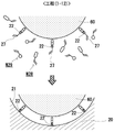
- the step (1-1) in the manufacturing method of the substrate-shaped base material 10a-C'for manufacturing an analysis sensor to be detected shown in FIG. 8A is schematically shown.
- the process (1-3) in the manufacturing method of the substrate-shaped base material 10a-C'for manufacturing an analysis sensor to be detected shown in FIG. 8A is schematically shown.
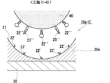
- FIG. 8A shows a step (1-4) in the manufacturing method of the substrate-shaped base material 10a-C'for manufacturing an analysis sensor to be detected.
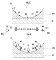
- a method of manufacturing the analysis sensor 10a-C to be detected on the substrate shown in FIG. 8B is schematically shown.
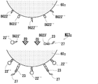
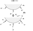
- the steps ( 1-11 ) (when the mold 601 is used) in the method for manufacturing the base material 10-P'for manufacturing the analytical sensor to be detected in the form of particles shown in FIG. 6 (A) are schematically shown.
- the steps (1-11) (when the mold 602 is used) in the method for manufacturing the substrate 10 - P'for manufacturing the analytical sensor to be detected in the form of particles shown in FIG. 6 (A) are schematically shown.
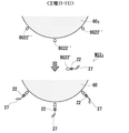
- the step (1-12) in the manufacturing method of the base material 10-P'for manufacturing an analytical sensor to be detected in the form of particles shown in FIG. 6 (A) is schematically shown.
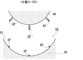
- An example of the step (1-13) in the method for manufacturing the base material 10-P'for manufacturing an analytical sensor to be detected in the form of particles shown in FIG. 6 (A) is schematically shown.
- a method for manufacturing the analysis sensor 10-P to be detected in the form of particles shown in FIG. 6B is schematically shown.
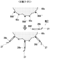
- the step (1-21) in the manufacturing method of the base material 10c-P'for manufacturing an analytical sensor to be detected in the form of particles shown in FIG. 10 (A) is schematically shown.
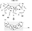
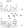
- the step (1-22) in the manufacturing method of the base material 10c-P'for manufacturing an analytical sensor to be detected in the form of particles shown in FIG. 10 (A) is schematically shown.
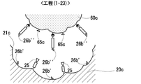
- the step (1-23) in the manufacturing method of the base material 10c-P'for manufacturing an analytical sensor to be detected in the form of particles shown in FIG. 10 (A) is schematically shown.
- the step (1-24) in the manufacturing method of the base material 10c-P'for manufacturing an analytical sensor to be detected in the form of particles shown in FIG. 10 (A) is schematically shown.
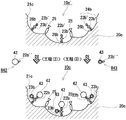
- a method for manufacturing the analysis sensor 10c-P to be detected in the form of particles shown in FIG. 10B is schematically shown.
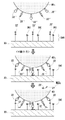
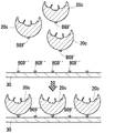
- the steps of fixing the particulate analysis target sensor base material to the substrate are schematically shown between FIGS. 14-3 and 14-4.
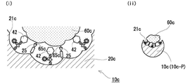
- An example of double targeting by the analytical sensor 10c-P of the particle-shaped detection target shown in FIG. 10B (in an environment where the concentration of the template (60c) of the molecular imprint recess 21c is high) is schematically shown.
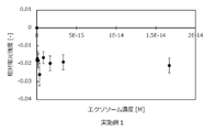
- Relative fluorescence intensity by the analysis sensor of the substrate-shaped detection target (exosome) of Example 3 (provided that the analysis sensor 101 type of the substrate - shaped detection target using a signal substance fused to a specific binding group). And the relationship between exosome concentration.
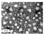
- the TEM image of the particulate molecular imprint polymer of the analysis sensor 10-PC of the detection target fixed to the particle and the substrate of Example 4 is shown.
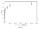
- the relationship between the amount of change in response and the concentration of exosome solution by the analysis sensor 10-PC of the detection target (exosome) in the form of particles and fixed to the substrate of Example 4 is shown.
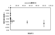
- the relationship between the relative fluorescence intensity and the exosome concentration by the analysis sensor 10b-PC of the detection target (exosome) in the form of particles and fixed to the substrate of Example 5 is shown.
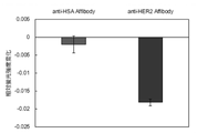
- the relative fluorescence intensity change when the exosome derived from the breast cancer cell line is added is shown.
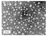
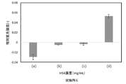
- the TEM image of the particulate molecular imprint polymer of the analysis sensor 10c-P of the particle-like detection target fixed on the substrate of Example 6 is shown. We show double targeting in solutions with different concentration ratios of exosomes and HSAs by the analysis sensor 10c-P of the particulate detection target (exosomes) fixed on the substrate of Example 6.
- the base material for manufacturing an analysis sensor to be detected in the present disclosure is a base material used as a material for manufacturing the analysis sensor of the invention described later.
- the base material for manufacturing the sensor for analysis is configured so that the user can easily customize the detection target to a sensor capable of detecting with higher sensitivity.
- the base material for producing an analysis sensor to be detected in the present disclosure includes a molecular imprint recess for receiving the target to be detected and a group for binding a specific binding molecule to the target provided in the molecular imprint recess.
- This basic configuration constitutes a sensing precursor portion (that is, a portion constituting the sensing unit when customized to the analysis sensor) of the base material for manufacturing the analysis sensor to be detected.
- target refers to a molecule or substance of interest.
- the target may be a molecule or a molecular assembly.
- small substance refers to any substance smaller than an antibody and can be used interchangeably with a "small binding molecular substance”. Since the standard of molecular weight is about 150,000, a molecular weight less than that (that is, less than 150,000) can be included in this concept.
- Preferred molecular weights are about 140,000 or less, about 130,000 or less, about 120,000 or less, about 110,000 or less, about 100,000 or less, about 90,000 or less, about 80,000 or less, about 70,000 or less, about 70,000 or less, About 60,000 or less, about 50,000 or less, about 40,000 or less, about 30,000 or less, about 22,000 or less, about 20,000 or less, about 19,000 or less, about 18,000 or less, about 17,000 or less, About 16,000 or less, about 15,000 or less, about 14,000 or less, about 13,000 or less, about 12,000 or less, about 11,000 or less, about 10,000 or less, about 9,000 or less, about 8 000 or less, about 7,000 or less, about 6,000 or less, and the like can be mentioned.
- the lower limit may be about 200 or more, about 300 or more, about 400 or more, about 500 or more, and about 600 or more.
- any kind of substance can be used, and typically proteins, polypeptides, peptides, sugars, lipids, nucleic acids, nucleic acid derivatives, artificial (polymer) receptors, and other organic molecules. , These complex molecules, and the like, preferably proteins, polypeptides, peptides, and more preferably proteins, or peptides.
- artificial (polymer) receptor refers to molecular imprint polymer nanoparticles (particle size, about 10 to 30 nm) that recognize targets. It is used in sandwich assays instead of antibodies.
- artificial receptors see Evan M. Peck and Bradley D. Smith, Chapter 1: Applications of Synthetic Receptors for Biomolecules, in Synthetic Receptors for Biomolecules: Design Princes and Applications, 2015, pp. 1-38. Can be done.
- binding group or “molecular imprint recess” is “fitted to " with respect to a substance to be adapted (for example, a small substance, a molecule having a molecular weight of 45,000, etc.).
- a substance to be adapted for example, a small substance, a molecule having a molecular weight of 45,000, etc.
- the configuration is such that proper detection is performed when performing a detection process on a substance to be matched. It means that you are doing.
- a "binding group suitable for a small substance” is a suitable binding group for a small substance smaller than an antibody, and is an amino group, a carboxy group, a boronic acid group, a cis-diol group, or an aldehyde group.
- Ketone group, oxyamino group, hydrazide group, biotin (biocithin, desthiobiotin) group, nickel-nitrilotriacetic acid derived group, thiol group, pyridyl disulfide group, metal complex and the like can be preferably utilized.
- the binding group is an Fc domain-binding protein of an antibody such as protein A, protein G, protein L, and protein A / G, a protein such as avidin, streptavidin, and neutravidin, an amino group, a carboxy group, and a boronic acid.
- the molecular imprint recess has a shape or configuration suitable for a small substance
- the molecular imprint recess has an appropriate shape and composition.
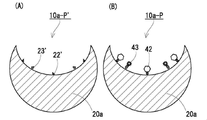
- FIGS. 1A, 2A, 3A, and 4A Some examples of the analysis sensor manufacturing substrate of the detection target of the present disclosure are shown in FIGS. 1A, 2A, 3A, and 4A, respectively, in FIGS. 1A, 10a', and 10b. It is schematically shown as', 10c'.
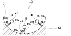
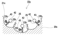
- the analysis sensor fabrication substrates of the present disclosure to be detected shown in these figures are schematically shown in FIGS. 1B-1, 1B-2, 2B-1, 2-2, 3B, and 4B, respectively. It is used for manufacturing the analysis sensors 10, 10 1 , 10a, 10a 1 , 10b, and 10c to be detected as shown in.
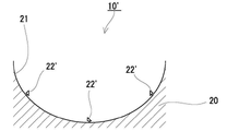
- the base material 10'for producing an analysis sensor to be detected shown in FIG. 1A has a molecular imprint recess 21 that receives the target to be detected and a specific binding molecule to the target provided in the molecular imprint recess 21. Includes a molecular imprint polymer 20 with a binding group 22'of.
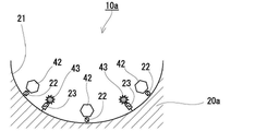
- the base material 10a'for manufacturing an analysis sensor to be detected shown in FIG. 2A has a molecular imprint recess 21 that receives the target to be detected and a specific binding molecule to the target provided in the molecular imprint recess 21. Includes a molecular imprint polymer 20a having a binding group 22'and a signaling group 23'. That is, the base material 10a'for manufacturing the analysis sensor to be detected is for manufacturing the analysis sensor to be detected in FIG. 1A, except that the group for binding the signal substance 23'is further provided in the molecular imprint recess 21. It is the same as the base material 10'.
- the binding group 22'of the specific binding molecule to the target and the binding group 23'of the signal substance are independent of each other on the surface of the molecular imprint recess 21. That is, they are separated from each other in the surface direction of the molecular imprint recess 21).
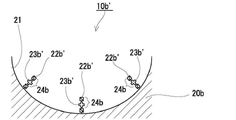
- the base material 10b'for producing an analysis sensor to be detected shown in FIG. 3A has a molecular imprint recess 21 that receives the target to be detected and a specific binding molecule to the target provided in the molecular imprint recess 21.
- the binding of the specific binding molecule to the target in the molecular imprint recess 21 constitute a predetermined functional group 24b.
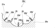
- the base material 10c'for producing an analysis sensor to be detected shown in FIG. 4A is a molecular imprint recess 21c that receives the target to be detected, and a molecule having a specific binding property to the target provided in the molecular imprint recess 21c. It contains a molecular imprint polymer 20c having a binding group 22b', a signaling group 23b' and an interacting group 25 with a template of the molecular imprint recess 21c. That is, the analysis sensor manufacturing substrate 10c'to be detected further contains a signal substance binding group 23b', and a binding group 22b'of a specific binding molecule to the target and a signaling substance binding group 23b.
- the analysis sensor manufacturing substrate 10b'of the detection target in FIG. 3A is constituting the predetermined functional group 24b'.
- the analysis sensor manufacturing base material 10c' to be detected further contains the interaction group 25, and the molecular imprint recesses 21c are mutual. It is limited to those formed by a template that interacts with the working group 25.
- the analysis sensor manufacturing substrates 10', 10a', 10b', and 10c'shown in FIGS. 1A, 2A, 3A, and 4A are shown in FIGS. 1B-1, 1B-2, and 2B-, respectively.
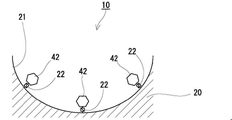
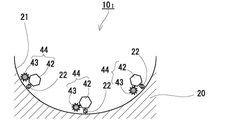
- At least the specific binding group 42 (small substance group) to the target is bound to the binding group 22', 22b'of the sex molecule, and the signal group 43 is bound to the binding group 23', 23b'of the signal substance.
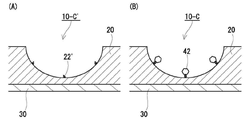
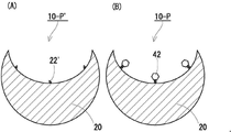
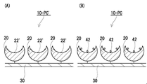
- FIGS. 5 (A), 6 (A), and 7 (A) More specific examples of the analysis sensor manufacturing substrate 10'of the present disclosure shown in FIG. 1A are shown in FIGS. 5 (A), 6 (A), and 7 (A) for analysis of the detection target. It is shown as a sensor manufacturing substrate 10-C', 10-P', 10-PC'.
- the analysis sensor manufacturing substrates 10-C', 10-P', and 10-PC'to be detected in the present disclosure are schematically shown in FIGS. 5 (B), 6 (B), and 7 (B), respectively. It is used for manufacturing the analysis sensors 10-C, 10-P, and 10-PC to be detected as shown in.
- the analysis sensor manufacturing base material 10-C'of the present disclosure to be detected shown in FIG. 5 (A) is a case where the analysis sensor manufacturing base material 10'to be detected of the present disclosure is in the form of a substrate (chip shape).
- the analysis sensor manufacturing substrate 10-C'to be detected includes the substrate 30 and the polymer film provided on the surface of the substrate 30, and the imprint polymer 10 constitutes the polymer film.
- the analysis sensor manufacturing base material 10-P'of the present disclosure to be detected shown in FIG. 6 (A) is an example in the case where the analysis sensor manufacturing base material 10'to be detected of the present disclosure is in the form of particles. That is, in the base material 10-P'for manufacturing the analysis sensor to be detected, the imprint polymer 10 is in the form of particles.
- the analysis sensor manufacturing substrate 10'to be detected in the present disclosure is fixed to the substrate (chip) in the form of particles.
- the detection target analysis sensor manufacturing base material 10-P'shown in FIG. 6A is fixed to the substrate 30. ing.
- a preferred example of the shape of the molecular imprint polymer is particulate matter.
- the fact that the molecular imprint polymer is in the form of particles means that the sensor for analysis to be detected can be detected by fixing it to a substrate like the base material 10-PC'for manufacturing the analysis sensor to be detected shown in FIG. 7 (A) above. Not only can it be shaped like a substrate (chip), but it can also be in a non-fixed state as in the analysis sensor manufacturing substrate 10-P'shown in FIG. 6 (A) above.
- the analysis sensor to be detected can be released (for example, dispersed in a dispersion medium), which is excellent in terms of versatility.
- the average particle size of the molecular imprint polymer in the form of particles varies depending on the size and application of the detection target or the target to be detected, and is, for example, a volume average measured by a dynamic light scattering method (DLS).
- the particle size is, for example, 5 to 500 nm, preferably 8 to 170 nm, more preferably 10 to 100 nm, still more preferably 15 to 50 nm, still more preferably 20 to 30 nm.
- the Z average particle size measured by DLS is, for example, 5 to 500 nm, preferably 50 to 350 nm, more preferably 80 to 200 nm, still more preferably 100 to 140 nm, and even more preferably 120 to 170 nm.
- the number average particle size measured by a transmission electron microscope is, for example, 5 to 150 nm, preferably 10 to 100 nm, more preferably 10 to 35 nm or 45 to 90 nm, still more preferably 20 to 30 nm.
- the number average particle size measured by a transmission electron microscope (TEM) is 100 particles randomly selected with the average value of the major axis and the minor axis of the particles in the transmission electron microscope image as the particle size. It is the average value of the diameter.
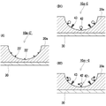
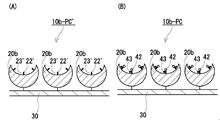
- all of the analysis sensor manufacturing substrates 10a', 10b', and 10c'shown in FIGS. 2A, 3A, and 4A to be detected in the present disclosure are in the form of a substrate (chip) or in the form of particles. It may be configured as a thing or a thing in the form of particles fixed to a substrate. Some examples thereof are shown in FIGS. 8 (A), 9 (A), 10 (A), and 11 (A), respectively. It is schematically shown as P', 10c-P', 10b-PC'.
- the base materials for manufacturing the analysis sensor to be detected in the present disclosure shown in these figures are FIGS. 5 (B), 6 (B), 7 (B), 8 (B1) and (B2), respectively. It is used for manufacturing the analysis sensor to be detected schematically shown in FIGS. 9 (B), 10 (B), and 11 (B).
- 10a - C, 10a1-C, 10a-P, 10c-P, 10b-PC at least to the binding groups 22', 22b' of the specific binding molecule to the target.
- the specific binding group 42 (small substance group) to the target is bound, and the signal group 43 is bound to the binding groups 23'and 23b'of the signal substance.
- the molecular imprint recesses 21 and 21c are portions that provide a sensor field in the analytical sensor of the present disclosure, and are formed to accept the target of the detection target.
- the molecular imprint recesses 21 and 21c are portions where the polymer is molded by a mold (molds 60 and 60c described later) used in the molecular imprint polymerization method, and is a part of the surface shape of the mold. Has a shape corresponding to.
- the recesses 21 and 21c may be formed at least in a size that can accept the target to be detected. Further, in the recesses 21 and 21c, the molecular imprint recess has a shape or a structure suitable for a small substance.
- the molecular imprint recesses 21 and 21c are "large enough to accept the target to be detected" when the specific binding group 42 to the target is introduced and becomes a sensor for analysis, at least a part of the detection target. (For example, at least the specific binding site with the specific binding group 42 in the target 72 of the detection target 70 described later) can enter the molecular imprint recesses 21 and 21c and approach the specific binding molecule to bind. It means that the molecular imprint recesses 21 and 21c are opened to such an extent that they are sufficiently large.
- the recesses 21 and 21c may use a substance having the same size as the detection target or the target to be detected, or a substance having a size larger than the detection target as a template.
- the recesses 21 and 21c use a substance having a size larger than the detection target or the target to be detected as a template.
- the binding groups 22'and 22b' of the specific binding molecule to the target are specific binding groups to the target (FIG. 1B-1, FIG. 1B-2, FIG. 2B-1, FIG. 2B-2, FIG. 3B, FIG. It is a group capable of introducing a specific binding molecule to a target by binding the specific binding group 42) in 4B.
- the user is free to select a target and can introduce a specific binding molecule to the selected target into the binding group 22', 22b'.
- the specific binding molecule is a binding molecule having high affinity and selectivity for a target.
- the base material for manufacturing the analysis sensor of the present disclosure includes the substrate 30, (for example, in the illustrated embodiment, FIGS. 5 (A), 7 (A), 8 (A), FIG.
- the analysis sensor manufacturing substrate 10-C', 10-PC'10a-C', 10b-PC', etc. of the present disclosure to be detected shown in 11 (A)) one on one substrate 30. Introduce one kind of specific binding molecule into the recesses 21 and 21c of the By introducing a molecule having a different specific binding group), it is possible to customize one substrate 30 so that the analysis target can be analyzed using a plurality of different binding groups.
- a specific method for introducing a plurality of types of specifically binding molecules into one substrate 30 is to fractionate a region on the substrate 30 into a plurality of regions and to perform different specific binding for each fractionated region. Examples include a method of introducing a sex molecule.
- a method of fractionation a polymer film made of a molecular imprint polymer (for example, the film-like molecular imprint polymers 20 and 20a shown in FIGS. 5A and 8A) or polymer particles (for example, polymer particles 20 and 20a) are formed on the substrate 30.
- FIG. 7 (A) and 11 (A) are absent; a polymer film made of the molecular imprint polymer (eg, FIG. 5 (A), A method of providing a portion where the recess 21 is absent on the film-shaped molecular imprint polymer 20 and 20a of FIG. 8A; a polymer film made of the molecular imprint polymer (for example, FIGS. 5A and 8A). ), A method of projecting a barrier on the film-shaped molecular imprint polymer 20, 20a) with a polymer or the like can be mentioned.
- a specific binding molecule that binds to a surface protein of a specific small extracellular vesicle is introduced into one recess 21,21c, and a specific recess 21,21c is introduced.
- a specific binding molecule that binds to a protein a protein that is not expressed on the surface of small extracellular vesicles
- both the small extracellular vesicles and the protein are on one substrate 30.
- a specific binding molecule that binds to the surface protein A of a specific small extracellular vesicle is introduced into one recess 21 and 21c, and the specific binding molecule is introduced into the other recess 31.
- a plurality of groups 22'and 22b' for binding a molecule having a specific binding property to a target are provided per one molecular imprint recess 21 or 21c.
- binding groups 22'and 22b' of the specific binding molecule are selected without particular limitation from those generally known as binding functional groups.
- the binding group 22'of the specific binding molecule is reversible from the groups generally known as the binding functional group.
- a group capable of forming a linking group (first reversible linking group 22 described later) is selected.
- a reversible linking group is a direct bond or a divalent or higher group whose cleavage (cleavage) and binding are reversible.
- the binding mode of the reversible portion of the reversible linking group (first reversible linking group 22 described later) may be covalent or non-covalent.
- binding group 22'of the specific binding molecule include the groups shown in column 1-1 of Table 1 below, and the corresponding reversible linking group (the first reversible linking group 22 described later). ) Can be mentioned, but is not limited to, the groups shown in columns 1-3 of Table 1 below.
- the binding group 22'of the specific binding molecule is preferably a group that forms a reversible linking group by a covalent bond or a coordinate bond.
- Reversible linking groups by covalent or coordinate bonds are relatively stable compared to hydrogen and hydrophobic bonds and remain stable during the polymerization reaction, facilitating the formation of molecular imprint recesses 21 and 21c.
- a reducing agent since it is easily cleaved by a reducing agent, heating at a relatively low temperature, hydrolysis under relatively mild conditions, light irradiation, etc., it is also easy to remove the template after the polymerization reaction.
- binding group 22'of the specific binding molecule include a metal complex, more preferably a nickel complex, still more preferably a nickel-nitrilotriacetic acid-derived group and the like. Be done.
- a case where the binding group 22'of such a specific binding molecule is suitable is a case where the molecular imprint polymer of the substrate for manufacturing the analysis sensor to be detected constitutes the polymer film (for example, FIG. 5).
- the case of the base material 10-C', 10a-C'for manufacturing the analysis sensor to be detected shown in FIG. 8 (A), etc. can be mentioned.
- binding functional groups a thiol group or a pyridyl disulfide group, more preferably a thiol group, can be mentioned as a suitable other example of the binding group 22'of the specific binding molecule.
- the molecular imprint polymer of the base material for manufacturing the analysis sensor to be detected is in the form of particles
- the case where the binding group 22'of such a specific binding molecule is suitable is, for example, FIG. 6 (A).
- 10-P', 10-PC', 10a-P', etc. which are the base materials for manufacturing the analysis sensor to be detected shown in FIGS. 7 (A) and 9 (A).
- the binding group 22b'of the specific binding molecule is reversible from the groups generally known as the binding functional group.
- a group capable of forming an irreversible linking group is selected.
- the binding group 22b'of the specific binding molecule is a reversible or irreversible linking group by covalent bond ( It is preferable that the group is capable of forming the linking group 22b) described later.
- Specific examples of the binding group 22b'of such a specific binding molecule include, but are not limited to, the groups shown in column 2-1 of Table 2 below.
- the chemically modified binding group is chemically modified.
- binding group 22b'of the specific binding molecule include a thiol group or a pyridyl disulfide group, and more preferably a pyridyl disulfide group.
- the binding groups 23'and 23b'of the signal substance are groups capable of introducing the signal substance by binding the signal groups (signal groups 43 in FIGS. 2B-1, 2B-2, 3B and 4B). Is. The user can freely select the signal substance and introduce it into the binding group 23', 23b'.
- a plurality of binding groups 23'and 23b' of the signal substance can be provided per one molecular imprint recess 21 and 21c.
- binding groups 23'and 23b'of the signal substance are generally known as binding functional groups as long as they are different groups from the binding groups 22'and 22b' of the specific binding molecule, respectively. It is selected from the ones without any particular limitation.
- the group 23'for binding the signal substance is a reversible linking group (the second group described later) from among the groups generally known as a binding functional group.
- a group capable of forming the reversible linking group 23) of 2 is selected.
- the binding mode of the reversible portion of the reversible linking group (second reversible linking group 23 described later) may be covalent or non-covalent.
- Specific examples of the group for binding 23'of the signal substance include the groups shown in column 1-1 of Table 1 above, and specific examples of the corresponding reversible linking group (second reversible linking group 23 described later). Examples include the groups shown in columns 1-3 of Table 1 above.
- the group for binding the signal substance 23' preferably a group that forms a reversible linking group by a covalent bond or a coordinate bond.
- Reversible linking groups by covalent or coordinate bonds are relatively stable compared to hydrogen and hydrophobic bonds and remain stable during the polymerization reaction, facilitating the formation of molecular imprint recesses 21 and 21c.
- a reducing agent since it is easily cleaved by a reducing agent, heating at a relatively low temperature, hydrolysis under relatively mild conditions, light irradiation, etc., it is also easy to remove the template after the polymerization reaction.
- binding group 23'of the signaling substance is a group forming a reversible linking group by covalent bond, more preferably a thiol group or a pyridyl disulfide group, and further preferably. Is a thiol group.
- the group 23b'for binding the signal substance is a reversible or irreversible linking group from among the groups generally known as a binding functional group.
- a group capable of forming is selected.
- a reversible or irreversible linking group can be formed as the binding group 23b'of the signal substance by covalent bonding. It is preferable that it is a basic group.
- Specific examples of the binding group 23b'of such a signal substance include the groups shown in column 2-1 of Table 2 above.
- binding functional groups an amino group is mentioned as a preferable example of the binding group 23b'of a signal substance.
- the binding group 22b'of the specific binding molecule and the binding group 23b'of the signal substance constitute the functional group 24b. Since the functional group 24b includes both the binding group 22b'of the specific binding molecule and the binding group 23b'of the signal substance in one group, these groups are used as the base material for manufacturing the analysis sensor to be detected. It becomes easy to install them in close proximity to each other. Providing the binding group 22b'of the specific binding molecule and the binding group 23b'of the signal substance in close proximity to each other in the base material for manufacturing the analysis sensor to be detected, that is, the specific binding property in the analysis sensor to be detected. The group 42 and the signal group 43 are provided close to each other, whereby the signal change can be obtained with higher sensitivity when the analysis sensor of the detection target recognizes the detection target.
- the binding group 22b'of the specific binding molecule is located on the distal end side of the functional group 24b, and the binding group 23b'of the signaling substance is located on the proximal end side of the functional group 24b.
- the positional relationship between the binding group 22b'of the specific binding molecule and the binding group 23b'of the signaling substance is specific to the binding group 22b' of the specific binding molecule.
- the binding group 42 can be specifically bound to the target to be detected and the signal group 43 bound to the binding group 23b'of the signaling substance is subjected to environmental changes when the binding group 42 is specifically bound
- the positional relationship is such that the binding group 43 is subjected to environmental changes. It is not limited to this.
- the positional relationship between the binding group 22b'of the specific binding molecule and the binding group 23b'of the signaling substance may be reversed from the illustrated embodiment.
- the binding group 22b'of the specific binding molecule is on the distal end side of the functional group 24b from the viewpoint of obtaining a signal change with higher sensitivity by changing the environment of the signal group 43 more reliably at the time of target binding.
- the binding group 23b'of the signal substance is located on the proximal end side of the functional group 24b.
- R 1 represents a linking group of a specific binding molecule
- L 1 represents a direct binding or linking group
- R 2 represents a linking group containing a linking group of a signaling substance.
- the binding group R 1 of the specific binding molecule is as described in "1-3-2. Binding group of the specific binding molecule to the target" above.
- the direct binding or linking group L 1 intervenes between the linking group R 1 of the specific binding molecule and the linking group R 2 containing the linking group of the signaling substance.
- the signal group 43 that binds to the binding group of the signal substance contained in the linking group R 2 and the specific binding group R 1 that binds to the binding group R 1 of the specific binding molecule is more preferably a linking group.
- the linking group may include an alkylene group containing a polyoxyalkylene group (for example, a C1 to 8 alkylene group or a polyoxy C1 to 3 alkylene C1 to 8 alkylene group), a carbonyl group, or the like. Examples include groups consisting of ester bonds (-COO- or -OCO-), amide bonds (-CONH- or -NHCO-), and any combination thereof. From the viewpoint of molecular design and the like, the linking group preferably is a combination of an alkylene group that may contain a polyoxyalkylene group and an ester bond and / or an amide bond, and more preferably an alkylene group that may contain a polyoxyalkylene group.
- a polyoxyalkylene group for example, a C1 to 8 alkylene group or a polyoxy C1 to 3 alkylene C1 to 8 alkylene group
- a carbonyl group or the like. Examples include groups consisting of ester bonds (-COO- or -OCO
- an ester bond or an amide bond more preferably one or more alkylene groups (the total number of carbon atoms of all the alkylene groups contained in the linking group is, for example, 1 to 8, preferably 2 to 6, more preferably. 3 to 5, particularly preferably 4) and an ester bond or an amide bond.
- the linking group of the signal substance in the linking group R 2 including the linking group of the signal substance is as described in "1-3-3. Binding group of the signal substance" above.
- the linking group R 2 containing the binding group of the signal substance is a non-branched or branched divalent group.
- the signaling substance binding group itself forms a linking group R 2 (that is, the linking group R 2 is composed of a signal substance binding group).
- a non-branched linking group R 2 that is, a signal substance binding group
- Examples of such a non-branched linking group R 2 that is, a signal substance binding group include a divalent amino group represented by the following formula (2).
- R 3 is an alkyl group having 1 to 8 carbon atoms (for example, a C1 to 8 alkylene group or a polyoxy C1 to 3 alkylene C1 to 8 alkylene group) which may contain hydrogen or a polyoxyalkylene group. ), Which preferably represents hydrogen.
- the signal substance binding group is a monovalent group present in the branch.
- Examples of such a linking group R 2 include a divalent group represented by the following formula (3).
- R 21 represents a nitrogen atom or a hydrocarbon
- L 21 represents a direct bond or a linking group
- R 22 represents a linking group of a signaling substance.
- R 21 is the hydrocarbon represented by —C—R 211 .
- the R 211 is not particularly limited, but for example, an alkyl group having 1 to 8 carbon atoms (for example, a C1-8 alkyl group or a polyoxy C1 to 3 alkylene C1 to 8 alkyl group) may contain a hydrogen atom or a polyoxyalkylene group.
- the hydrogen atom is preferably mentioned.
- a linking group is more preferable from the viewpoint of more effectively suppressing interference with the specific recognition of the detection target with respect to the specific binding group 42 that binds to 1 .
- the linking group may include an alkylene group containing a polyoxyalkylene group (for example, a C1 to 8 alkylene group or a polyoxy C1 to 3 alkylene C1 to 8 alkylene group).
- a polyoxyalkylene group for example, a C1 to 8 alkylene group or a polyoxy C1 to 3 alkylene C1 to 8 alkylene group.
- the linking group is preferably an alkylene group containing a polyoxyalkylene group, more preferably 1 to 6 carbon atoms (preferably 1 to 4, more preferably 1 to 3), and particularly preferably. 2) alkylene group can be mentioned.
- the group for binding R22 of the signal substance is as described in "1-3-3. Group for binding the signal substance" above.
- the interaction group 25 in the analysis sensor manufacturing substrate 10c shown in FIG. 4A is a group that interacts with the interaction site (interaction site 65c described later) in the template of the molecular imprint recess 21c.
- Examples of the template corresponding to the interaction group 25 include biomolecules such as proteins and glycoproteins.
- the interaction group 25 are designed according to the surface state of the corresponding mold, that is, the interaction group of the mold.
- examples thereof include groups capable of forming a hydrophobic bond with a specific hydrophobic region of the protein to be used.
- the aromatic groups in the [2] substituted or unsubstituted aromatic group include [21] substituted or unsubstituted nitrogen-containing aromatic groups and [22] substituted or unsubstituted non-nitrogen aromatic groups.
- the interaction group 25 may be a group consisting of any of these groups, or may be a group containing two or more combinations selected from these groups.
- the combinations of the interaction group 25, the corresponding interaction sites (interaction sites 65c described below), and the types of non-covalent bonds formed by their interactions are shown in the table below. Not limited.
- substituted or unsubstituted amino group as the substituent in the substituted amino group, a linear or branched alkyl group having 1 to 8 carbon atoms, a substituted or unsubstituted aralkyl group; a cyclic secondary amino group may be used. Examples thereof include an alkenyl group having 4 to 6 carbon atoms as a constituent; a substituted or unsubstituted aryl group and the like.
- Specific examples of the substituted or unsubstituted aryl group include the groups listed in [251] substituted or unsubstituted nitrogen-containing aryl group and [252] substituted or unsubstituted non-nitrogen aryl group described later.
- substituted or unsubstituted amino groups include amino groups (unsubstituted); N-methylamino groups, N-ethylamino groups, Nn-propylamino groups, N-isopropylamino groups, N.
- Secondary amino groups such as -n-butylamino group, N-isobutylamino group, N-tert-butylamino group, N-benzylamino group, N-phenylamino group, N-mesylamino group, N-tosylamino group; N , N-dimethylamino group, N, N-diethylamino group, N, N-dibenzylamino group, N-ethyl-N-methylamino group, N, N-di-n-propylamino group, N, N-diisopropyl Secondary amino groups such as amino groups, N, N-diphenylamino groups, N-methyl-N-phenylamino groups, N-methyl-N-benzylamino groups, N-mesyl-N-methylamino groups; piperidyl groups, Examples thereof include a cyclic secondary amino group such as a pyrrolidyl group. Among these substituted or unsub
- the nitrogen-containing aryl group in the [251] substituted or unsubstituted nitrogen-containing aryl group includes a nitrogen-containing aryl group having 2 to 12 carbon atoms.
- the substituent in the substituted nitrogen-containing aryl group include a linear or branched alkyl group having 1 to 8 carbon atoms.
- substituted or unsubstituted nitrogen-containing aryl group examples include a pyridyl group, a pyrimidyl group, a pyridazyl group, a pyrazil group, an imidazolyl group, a triazolyl group, and a methylpyridyl group (2-methylpyridyl group, 3-methylpyridyl).
- the non-nitrogen aryl group in the [252] substituted or unsubstituted non-nitrogen aryl group includes a phenyl group and a naphthyl group having 6 to 16 carbon atoms. 1-naphthyl group, 2-naphthyl group, etc.) and the like.
- the substituent in the substituted aryl group include a linear or branched alkyl group having 1 to 8 carbon atoms, a nitro group, a halogen group (fluoro group, chloro group, bromo group, etc.) and the like.
- substituted or unsubstituted aryl group examples include a phenyl group, a naphthyl group, a trill group (o-tolyl group, m-tolyll group, p-tolyl group, etc.), and an ethylphenyl group (4-ethylphenyl group).
- the monovalent group among the groups [1] to [7] is substituted with [1].
- Boronyl groups include groups comprising a combination of a [26] substituted or unsubstituted arylene group ([261] nitrogen-containing arylene group, [262] non-nitrogen-containing arylene group).
- the [261] nitrogen-containing arylene group constitutes an aromatic ring from the groups listed above as the [251] substituted or unsubstituted nitrogen-containing aryl group. It is a group from which one hydrogen bonded to the carbon is removed.
- the [262] non-nitrogen-containing arylene group constitutes an aromatic ring from the groups listed above as the [252] substituted or unsubstituted non-nitrogen aryl group. It is a group from which one hydrogen bonded to the carbon is removed.
- Specific groups including two or more combinations selected from the above [1] to [7] groups include amidino, which is a combination of a [3] amidino group and a [26] substituted or unsubstituted arylene group.
- An aryl group a carboxyaryl group which is a combination of a [5] carboxyl group and a [26] substituted or unsubstituted arylene group, a sulfo which is a combination of a [6] sulfo group and a [26] substituted or unsubstituted arylene group.
- Examples thereof include an aryl group, a boronylaryl group which is a combination of a [7] boronyl group and a [26] substituted or unsubstituted arylene group.
- a boronylaryl group which is a combination of a [7] boronyl group and a [26] substituted or unsubstituted arylene group.
- preferable groups are shown below.
- the components of the polymers constituting the molecular imprint polymers 20, 20a, 20b, and 20c are not particularly limited.
- the polymer has a constituent unit selected from the group consisting of biocompatible monomer-derived units, N-substituted or unsubstituted (meth) acrylamide-derived units, and functional monomer-derived units having the above-mentioned interaction group 25. include.
- the polymer synthesized by imprinting polymerization using a template is referred to as "molecular imprint polymer" for convenience, and in the present disclosure, a non-molecular polymer (for example, a film structure) is used as a template.
- the "molecular imprint polymer” also includes a polymer synthesized by imprinting polymerization using a non-molecular template.
- the polymer constituting the molecular imprint polymer 20, 20a, 20b, 20c preferably contains at least a component derived from a biocompatible monomer.
- Biocompatibility refers to the property of not inducing the adhesion of biological substances.
- a component derived from a biocompatible monomer for example, exemplified as the biocompatible monomer M28 described later
- non-specific adsorption to the surface of the molecular imprint polymers 20, 20a, 20b, 20c is satisfactorily suppressed. can do.
- the biocompatible monomer include a hydrophilic monomer, and more preferably a zwitterionic monomer.
- the twin ion monomer includes an anionic group derived from an acidic functional group (for example, a phosphate group, a sulfate group, and a carboxyl group) and a basic functional group (for example, a primary amino group, a secondary amino group, and a tertiary group). Both an amino group and a cationic group derived from a quaternary ammonium group) are contained in one molecule. For example, phosphobetaine, sulfobetaine, and carboxybetaine may be mentioned.
- examples of the phosphobetaine include molecules having a phosphorylcholine group in the side chain, and preferably 2-methacryloyloxyethylphosphorylcholine (MPC) and the like.
- MPC 2-methacryloyloxyethylphosphorylcholine
- sulfobetaines include N, N-dimethyl-N- (3-sulfopropyl) -3'-methacryloylaminopropaneaminium inner salt (SPB), N, N-dimethyl-N- (4-sulfobutyl) -3'.
- SPB N-dimethyl-N- (3-sulfopropyl) -3'-methacryloylaminopropaneaminium inner salt
- SBB -Methacrylaminopropaneaminium inner salt
- carboxybetaine examples include N, N-dimethyl-N- (1-carboxymethyl) -2'-methacryloxyethaneaminium inner salt (CMB), N, N-dimethyl-N- (2-carboxyethyl)-. Examples thereof include 2'-methacryloyloxyethane aminium inner salt (CEB).
- phosphobetaine is preferable, and 2-methacryloyloxyethyl phosphorylcholine (MPC) is more preferable.
- Examples of the ratio of biocompatible monomer-derived units in all the constituent units of the molecular imprint polymers 20, 20a, 20b, and 20c include 1 mol% or more and 100 mol% or less. It is preferable that the content of the biocompatible monomer-derived unit is at least the above lower limit in that non-specific adsorption on the surfaces of the molecular imprint polymers 20, 20a, 20b and 20c is suppressed. Further, the preferable range of the ratio of the biocompatible monomer-derived unit may vary depending on the shape of the molecular imprint polymers 20, 20a, 20b, 20c.
- the preferable range of the ratio of the biocompatible monomer-derived unit is 30 mol% or more, more preferably 50 mol% or more, still more preferable. Is 70 mol% or more, more preferably 80 mol% or more, still more preferably 90 mol% or more, and particularly preferably 95 mol% or more.
- the preferred range of the proportion of the biocompatible monomer-derived unit is 1 to 50 mol%, preferably 2 to 30 mol%, and more. It is preferably 3 to 10 mol%, more preferably 4 to 6 mol%, and particularly preferably 4.5 to 5.5 mol%.
- the polymers constituting the molecular imprint polymers 20, 20a, 20b, 20c can contain N-substituted or unsubstituted (meth) acrylamide-derived units.
- the constituent polymer contains N-substituted or unsubstituted (meth) acrylamide-derived units.
- N-substituted or unsubstituted (meth) acrylamide (for example, exemplified as the polymerizable monomer M29 described later) is represented by the following formula (4).
- R 41 represents hydrogen or a methyl group, preferably hydrogen, and R 42 and R 43 are independently hydrogen; a linear or branched alkyl group having 1 to 6 carbon atoms.
- R 42 and R 43 may form a saturated 5- to 7-membered ring containing an oxygen atom together with the nitrogen atom carrying them.
- the linear or branched alkyl group having 1 to 6 carbon atoms includes a methyl group, an ethyl group, an n-propyl group, an isopropyl group, an n-butyl group, a sec-butyl group, a tert-butyl group and an n-. Examples thereof include a pentyl group and an n-hexyl group.
- the linear or branched hydroxyalkyl group having 1 to 6 carbon atoms includes a hydroxymethyl group, a 1-hydroxyethyl group, a 2-hydroxyethyl group, a 1-hydroxy-n-propyl group, and a 2-hydroxy-n.
- the linear or branched aminoalkyl group having 1 to 6 carbon atoms includes an aminomethyl group, a 1-aminoethyl group, a 2-aminoethyl group, a 1-amino-n-propyl group, and a 2-amino-n.
- -Propyl group 3-amino-n-propyl group, 1-aminoisopropyl group, 2-aminoisopropyl group, 1-amino-n-butyl group, 1-amino-n-pentyl group, 1-amino-n-hexyl Group etc. can be mentioned.
- Examples of the saturated 5- to 7-membered ring containing an oxygen atom as well as a nitrogen atom include a morpholine ring and the like.
- N-substituted or unsubstituted (meth) acrylamides N-substituted (meth) acrylamides are preferable, N-mono-substituted (meth) acrylamides are more preferable, and N-mono-substituted (meth) acrylamides are more preferable.
- Alkyl (meth) acrylamide (the alkyl group is the above-mentioned linear or branched alkyl group having 1 to 6 carbon atoms) is mentioned, more preferably N-isopropyl (meth) acrylamide is mentioned, and particularly preferably. Examples include N-isopropylacrylamide.
- the polymer constituting the molecular imprint polymers 20, 20a, 20b, 20c contains N-substituted or unsubstituted (meth) acrylamide-derived units, N in all the constituent units of the molecular imprint polymers 20, 20a, 20b, 20c.
- the proportion of substituted or unsubstituted (meth) acrylamide-derived units is, for example, 1 to 99 mol%, preferably 10 to 98 mol%, more preferably 30 to 96 mol%, still more preferably 50 to 94 mol%. More preferably, it is 70 to 92 mol%, further preferably 80 to 90 mol%, and particularly preferably 85 to 90 mol%.
- the polymer constituting the molecular imprint polymer 20c contains a unit derived from a functional monomer.
- the functional monomer is not particularly limited as long as it is a monomer having the interaction group 25 described in "1-3-5. Interaction group" above (for example, as the monomer M25 containing an interaction group with a template described later). Illustrated).
- Examples of the functional monomer without limitation include the monomer represented by the following formula (5).
- R 51 represents hydrogen or a methyl group, preferably hydrogen
- L 5 represents a direct bond or linking group
- R 52 is described in the above "1-3-5.
- Interaction group Represents the interaction group 25.
- the linking group includes, for example, an alkylene group having 1 to 6 carbon atoms, preferably 2 to 6 carbon atoms, an amino group (-NH-), and an ether group (-O).
- the competent monomer-derived unit is present at least on the surface of the recess 21c.
- the capable monomer-derived unit may be present not only on the surface of the recess 21c but also inside.
- the ratio of the functional monomer-derived unit to all the structural units of the polymer constituting the molecular imprint polymer 20c is not particularly limited, and depends on the surface state of the corresponding template (the number of sites that interact with the interaction 25).
- the proportion of the functional monomer-derived unit in all the constituent units of the polymer constituting the molecular imprint polymer 20c is, for example, 1 to 30 mol%, preferably 3 to 20 mol%, more preferably 5 to 10 mol%. More preferably, 6 to 8 mol% is mentioned.
- a monomer further imparting a binding group of the specific binding molecule (a binding group of the specific binding molecule described later and a polymerizable functionality).
- Examples of the case where a monomer-derived unit that provides a binding group for a specific binding molecule is present include cases where the molecular imprint polymers 20, 20a, and 20b are in the form of particles.
- Examples of the case where the monomer-derived unit providing the binding group of the signal substance is present include the case where the molecular imprint polymers 20, 20a and 20b are in the form of a film.
- the material of the substrate 30 may be, for example, a material selected from the group consisting of metal, glass, and resin.
- the metal include gold, silver, copper, aluminum, tungsten, molybdenum and the like.
- Resins include poly (meth) acrylate, polystyrene, ABS (acrylonitrile-butadiene-styrene copolymer), polycarbonate, polyester, polyethylene, polypropylene, nylon, polyurethane, silicone resin, fluororesin, methylpentene resin, phenol resin, and melamine. Examples thereof include resins, epoxy resins, vinyl chloride resins and the like.
- the substrate 30 may be formed by combining a plurality of materials selected from the above-mentioned materials.
- the base material 20 may have a metal film provided on the surface of glass or resin.
- the shape of the base material 20 may be plate-shaped or particle-shaped. Preferred examples include a gold substrate, a glass substrate, gold nanoparticles, silicon dioxide particles (silica particles, glass beads, etc.) and the like.
- the base material for making an analytical sensor to be detected in the present disclosure may be configured such that at least one of a specific binding molecule and a signal substance is customized by the user. Therefore, as another embodiment, the specific binding group 42 to the target may already be bound to the binding group 22', 22b' of the specific binding molecule. In this case, the user can freely select and introduce the signal substance.
- the signal group 43 may already be bound to the binding groups 23'and 23b'of the signal substance.
- the user can freely target the detection target, freely select the target detection target, and introduce a specific binding molecule to the detection target.
- the analytical sensors of the present disclosure include the above-mentioned base material for making an analytical sensor to be detected; and a specific binding group to the target to be detected bound to the binding group of the specific binding molecule.
- the binding group of the specific binding molecule is a group suitable for a small substance.
- the analytical sensor of the present disclosure comprises the above-mentioned base material for making an analytical sensor to be detected; a specific binding group to the target to be detected bound to the binding group of the specific binding molecule. Containing and having a molecular imprint recess having a shape or configuration suitable for a small substance.
- the analytical sensor of the present disclosure also includes a signal group bonded to the binding group of the signal substance when the above-mentioned base material for manufacturing the analytical sensor to be detected has a binding group of the signal substance.
- FIGS. 1B-1, 1B-2, 2B-1, 2B-2, 3B, and 4B Examples of the analytical sensors of the present disclosure are shown in FIGS. 1B-1, 1B-2, 2B-1, 2B-2, 3B, and 4B, and the analytical sensors 10, 10 1 , 10a, 10a to be detected. Shown as 1 , 10b, 10c. As shown, the analytical sensors 10, 10 1 , 10a, 10a 1 , 10b, 10c to be detected are specific to the target of the analytical sensor fabrication substrate 10', 10a', 10b', 10c' to be detected. At least the specific binding group 42 to the target is bound to the binding group 22', 22'b of the binding molecule, and the signal group 43 is bound to the binding group 23', 23b'of the signaling substance. ..
- FIGS. 5 (B), 6 (B), 7 (B), 8 (B1), (B2), 9 (B), and FIG. 10 (B) and 11 (B) show the analysis sensors 10-C, 10-P, 10-PC, 10a-C, 10a 1 -C, 10a-P, 10c-P, 10b-PC to be detected. Shown as. As shown, specific binding molecules to the target of the analytical sensors 10-C, 10-P, 10-PC, 10a-C, 10a-P, 10a1 - C, 10c-P, 10b-PC to be detected. At least the specific binding group 42 to the target is bound to the binding groups 22'and 22b', and the signal group 43 is bound to the binding groups 23'and 23b'of the signaling substance.
- the detection target of the analytical sensor of the present disclosure is not particularly limited in principle as long as it includes a target and the target has a specific binding ability to the specific binding group 42.
- the detection target may be the target itself (that is, the detection target is composed of the target; hereinafter, also referred to as “Aspect 1”), or the detection target (for example, “Aspect 1”).
- a part of the detection target 70) described later may be composed of a target (for example, the target 72 described later) (hereinafter, also referred to as “aspect 2”).
- the chemical species of the detection target (aspect 1) or the target of detection (aspect 2) is not particularly limited, and for example, low molecular weight organic compounds and high molecular weight compounds which are not derived from living organisms, low molecular weight organic compounds and high molecular weight which are derived from living organisms.
- Molecular compounds can be mentioned.
- these chemical species preferably low molecular weight organic compounds and high molecular weight compounds derived from living organisms are mentioned, and more preferably low molecular weight organic compounds and high molecular weight compounds derived from animals are mentioned, and specific examples are sugars or sugars. Examples thereof include sugar chains; lipids (eg, phospholipids, etc.); glycoproteins or glycopeptides; proteins or peptides; nucleotides or polynucleotides.
- Examples of the organism of origin include humans and non-human animals, examples of non-human animals include vertebrates, preferably mammals, such as mice, rats, monkeys, dogs, cats, etc. Examples include cattle, horses, pigs, hamsters, rabbits, and goats.
- the functional species of the detection target (aspect 1) or the detection target (aspect 2) is not particularly limited, and plasma proteins, disease markers, antigens, antibodies, receptors, prions, micrograins having a membrane structure, etc. Can be mentioned.
- the target thereof is an antigen, an antibody, a receptor, and / or an antigen, an antibody, a receptor, and / or an antigen, an antibody, a receptor, and / or an antigen, an antibody, a receptor, and / or an antigen, an antibody, a receptor, and / or an antigen, an antibody, a receptor, and / or an antigen, an antibody, a receptor, and / or an antigen, an antibody, a receptor, and / or an antigen, an antibody, a receptor, and / or an antigen, an antibody, a receptor, and / or an antigen, an antibody, a receptor, and / or an antigen, an antibody, a receptor, and / or an antigen, an antibody, a
- plasma proteins include albumin, ⁇ -globulin, fibrinogen and the like.
- diseases marker include renal function marker, liver function marker, inflammation marker, tumor marker and the like, and more specifically, urinary albumin, aspartate aminotransferase (AST), alanine aminotransferase (ALT), transferase, and the like.
- LDH lactate dehydrogenase
- ALP alkaline phosphatase
- ⁇ -GTP ⁇ -glutamyl transpeptidase
- CRP C-reactive protein
- AFP ⁇ -fetoprotein
- sugar chain antigen 19-9 CA19-9
- CEA Carcinoembryonic antigen
- PSA prostate-specific antigen
- micrograins having a membrane structure include extracellular vesicles, intracellular vesicles, organelles, and cells.
- the membrane structure include a lipid bilayer membrane structure.
- extracellular vesicles include exosomes, microvesicles, apoptotic bodies and the like.
- intracellular vesicles include lysosomes and endosomes.
- organelles include mitochondria.
- cells include cancer cells such as circulating tumor cells (CTC), other disease-related cells and the like.
- CTC circulating tumor cells
- exosome-specific antigens or exosome antigens include CD63, CD9, CD81, CD37, CD53, CD82, CD13, CD11, CD86, ICAM-1, Rab5, Annexin V, LAMP1, Proteins such as EpCAM and HER2; lipids; sugar chains and the like can be mentioned.
- Targets expressed on the surface of cancer cells include Caveolin-1, EpCAM, FasL, TRAIL, Galectine3, CD151, Tetraspanin 8, EGFR, HER2, RPN2, CD44, TGF- ⁇ and the like.
- Examples include proteins; lipids; sugar chains and the like.
- the signal substance R43 is configured as one of the fluorescent dye pairs that cause fluorescence resonance energy transfer (FRET)
- FRET fluorescence resonance energy transfer
- the specific binding group 42 is a small substance group, preferably a specific binding protein group or peptide group having a molecular weight of 45,000 or less.
- the molecular weight is the calculated molecular mass. Means.
- the small substance group is typically a molecule having a molecular weight smaller than that of an antibody, and is a substance having a molecular weight of less than 150,000, preferably a substance having a molecular weight of 100,000 or less, more preferably a substance having a molecular weight of 45,000 or less, still more preferably. It is a group of 22,000 or less, more preferably 16,000 or less, even more preferably 10,000 or less, and any substance can be used, but preferably a protein, polypeptide or peptide.
- the molecular weight of the specific binding group 42 is preferably 40,000 or less, more preferably 30.000 or less, still more preferably 22,000 or less, still more preferably 16. 000 or less, more preferably 10,000 or less, and particularly preferably 8,000 or less.
- the specific binding group 42 is not particularly limited as long as it has a specific binding ability to the target to be detected and is a small substance group (however, Fab', Fab, scFv are excluded). do not have.
- the specific binding group 42 is a group introduced by a specific binding molecule (specific binding molecule R42 described later) that imparts a specific binding group 42, and the specific binding molecule (specifically described later).
- Specific examples of the binding molecule R42) include antibody mimetics, phospholipid-binding proteins, lectins and the like.
- Nanobodies have a natural heavy chain antibody structure and contain a single variable domain (VHH) and two constant domains (CH2 and CH3).
- Specific examples of the Nanobody include, but are not limited to, anti-EGFR Nanobody, anti-HER2 Nanobody, anti-MUC1 Nanobody, anti-integrin Nanobody, anti-TNF Nanobody, and the like.
- the antibody mimetic is an arbitrary substance that can specifically bind to an antigen like an antibody, but is not structurally related to an antibody, and an organic compound (which does not have an antibody binding domain) is exemplified.
- Specific antibody mimetics include Affibody (scaffold protein: Z domain of protein A, molecular weight: about 6,000, non-limiting specific examples: anti-Her2 Affibody, anti-EGFR Affibody, anti-TNF- ⁇ Affibody, Anti-HSA affibody, anti-transferase affibody, anti-fibrinogen affibody, anti-IgM affibody, etc.); : Cystatin, molecular weight: about 12,000 to 14,000); affitin (scaffold protein: Sac7d, molecular weight: about 7,000); alpha body (scaffold protein: triple spiral coiled coil, molecular weight: about 10,000); anticarin (Scoop protein: lipocalin, mo
- Scaffold protein 10th type III domain of fibronectin, molecular weight: about 10,000, non-limiting specific example: anti-EGFR1 Monobody, anti-HER2 monobody, etc.); nanoCLAP (scaffold protein: carbohydrate binding module 32-2 (Clostridium perfringens NagH), molecular weight: about 16,000), nanobody (for example, recombination of VHH antibody possessed by camels and alpaca) Protein) and the like, but are not limited to these.
- Phospholipid-binding protein is a protein that exhibits phospholipid-binding activity.
- Specific examples of the phospholipid-binding protein include, but are not limited to, Evectin 2, Annexin A2, Annexin V, Tim4 and the like.
- Lectin is a protein that exhibits binding activity to sugar chains.
- lectins include C-type lectins, kinase-like lectins, F-box lectins, F-type lectins, ficholine-mannose-binding lectins, galectins, X-lectins, L-type lectins, M-type lectins, P-type lectins, and R. Examples thereof include, but are not limited to, type lectins, tachylectins, and sialic acid-binding lectins.
- Examples of substances having a specific binding ability to a target to be detected other than proteins and peptides include the following.
- Sugar As sugar, ⁇ -cyclodextrin (6 D-glucose linked) and ⁇ -cyclodextrin (7 D-glucose), which are cyclic oligosaccharides in which D-glucose is linked by ⁇ -1,4 glycosidic bond, are linked.
- ⁇ -cyclodextrin 8 D-glucose linked
- ⁇ -cyclodextrin (8 linked D-glucose linked D-glucose).
- the inside of these annular structures is a hydrophobic cavity.
- the molecule that matches the cavity size is recognized and included in the hydrophobic interaction, it can be used as a molecule having a specific binding ability to the target to be detected.
- Glycosaminoglucan having a repeating structure of a disaccharide with a sulfate group added For example, hyaluronic acid is used as a molecule having a specific binding ability to CD44 because it recognizes and binds to the membrane protein CD44. It is possible.
- heparin is present on the cell surface and interacts with various extracellular matrix proteins that have heparin binding domains. Therefore, it can be used as a molecule having a specific binding ability to a protein having a heparin binding domain.
- proteoglycans in which a sugar chain is bound to a peptide are also found, and can be used as a molecule having a specific binding ability to a target to be detected.
- Lipids Phospholipids, for example, phospholipids having a phosphate ester, have various functional groups that can be bound by the phosphate ester, and phospholipids can interact with various biomolecules, so that they are targets to be detected. It can be used as a molecule having a specific binding ability to the ester.
- Nucleic acid Nucleic acid is known as a nucleic acid aptamer as a nucleic acid molecule that specifically binds to a specific molecule.
- the inherent binding ability of a specific binding molecule that imparts a specific binding group 42 to a target is inferior to that of the antibody.
- the dissociation constant Kd is larger than that of the antibody, the binding ability per target is significantly enhanced by providing the specific binding group 42 in the molecular imprint recesses 21 and 21c (that is, the dissociation constant). Kd is significantly reduced), and its significantly improved binding ability may even surpass the binding ability of the antibody per target when the antibody is introduced into the molecular imprint recesses 21 and 21c.
- the analytical sensor of the present disclosure even if the specific binding group 42 having a lower binding ability than the antibody is introduced into the molecular imprint recesses 21 and 21c, the antibody is introduced into the molecular imprint recesses 21 and 21c. It is possible to develop a sensitivity that exceeds that of the analytical sensor introduced in. From this point of view, as an example of the specific binding molecule (specific binding molecule R42 described later) that provides the specific binding group 42 in the analytical sensor of the present disclosure, the inherent binding ability of itself is Examples thereof include those that are inferior to the inherent binding ability of the antibody (the dissociation constant Kd is larger than that of the antibody).
- the analytical sensor of the present disclosure significantly enhances the binding ability of the specific binding group 42 per target, the specific binding molecule that imparts the specific binding group 42 (specific binding described later).
- the sex molecule R42 a molecule having an enhanced inherent binding ability by subjecting a modification such as a mutation to enhance the binding ability may be used.
- the specific binding group 42 is a group (specific binding group having a signal group) 44 to which the signal group 43 is further bound. May be good.
- Specific examples of the specific binding group 44 having such a signal group include a modified protein or peptide in which the specific binding group 42 has the signal group 43 as a modifying group; the specific binding group 42 and the protein or peptide. Examples thereof include a fusion protein or peptide fused with the signal group 43.
- the inherent binding ability of the specific binding group 42 in the specific binding group 44 having a signal group is due to the influence of the presence of the signal group 43, that is, the specific binding group 42 having no signal group 43 ( For example, it is inferior to the intrinsic binding ability of the specific binding group 42) in the analytical sensors 10, 10a, 10b, 10c of FIGS. 1B-1, 2B-1, 3B, and 4B.
- the analytical sensor of the present disclosure is excellent in the effect of improving sensitivity, even if a specific binding group having a signal group, such as a specific binding group 44 having a signal group, which has a reduced inherent binding ability, is used, it is possible to use the specific binding group.
- the binding ability can be effectively improved, and an excellent sensitivity improving effect can be achieved.
- the signal group 43 and the specific binding group 42 are shown in FIG. 2B rather than the mode in which they are bound to each other. It is preferable that the recesses of the molecular imprint are separated from each other in the surface direction, or that the functional group 24b (see FIG. 3A) is interposed as shown in FIG. 3B.
- the specific binding group 42 is a group to which another signal group sg is further bound (a specific binding group having another signal group). It may be 42 1 .
- the signal group 43 bound to the specific binding group 42 shown in FIG. 1B -2 is used for sensing the analysis sensor 101 to be detected, whereas the specific binding property shown in FIG. 2B-2 is shown above.
- the other signal group sg bound to the group 42 differs in that it is not used for sensing the analytical sensor 10a 1 to be detected. Since the molecular weight of the specific binding group 42 is small, other signal groups sg facilitate handling of the specific binding molecule (specific binding molecule R42 described later) that imparts the specific binding group 42, and the like.
- the signal group 43 is used instead of the other signal group sg for sensing the analysis sensor 10a 1 to be detected shown in FIG. 2B-2.
- the specific binding group 421 having such another signal group include a modified protein or peptide in which the specific binding group 42 has another signal group sg as a modifying group; the specific binding group 42. And a fusion protein or peptide fused with another signal group sg which is a protein or peptide.
- the innate binding ability of the specific binding group 42 in the specific binding group 421 having the other signal group does not have the other signal group sg due to the influence of the presence of the other signal group sg. From the intrinsic binding ability of the specific binding group 42 (for example, the specific binding group 42 in the analytical sensors 10, 10a, 10b, 10c of FIGS. 1B-1, 2B-1, 3B, 4B). Is also inferior.
- the analytical sensor of the present disclosure has an excellent effect of improving sensitivity
- a specific binding group having a reduced inherent binding ability such as a specific binding group 421 having another signal group is used.
- the binding ability can be effectively improved and an excellent sensitivity improving effect can be obtained.
- the signal group 43 functions as a device for reading out binding information between the target to be detected and the specific binding group 42 to the target.
- the signal group 43 is not particularly limited as long as the signal intensity detected by the binding of the target in the molecular imprint recesses 21 and 21c changes or the spectrum changes (for example, the peak shifts).
- examples of the signal substance (signal substance R43 described later) that gives the signal group 43 include a fluorescent substance, a radioactive element-containing substance, a magnetic substance, and the like. From the viewpoint of detectability and the like, the signal substance is preferably a fluorescent substance.
- fluorescent substance examples include cyanine dyes such as fluorescein dye and indocyanine dye (DY647, Cy5, DY490, etc.), rhodamine dyes (CR110, TAMRA), coumarin dyes, EvoBlue dyes, oxazine dyes (ATTO), carbopyronine dyes, Alexa dyes, etc.
- Fluorescent dyes such as; fluorescent proteins such as GFP; nanoparticles such as gold colloids and quantum dots.
- radioactive element-containing substance include sugars, amino acids, nucleic acids labeled with a radioisotope such as 18F , and an MRI probe labeled with 19F .
- the magnetic substance examples include those having a magnetic substance such as ferrichrome, ferrite nanoparticles, nanomagnetic particles and the like.
- rhodamine dyes are preferable from the viewpoint of further improving the detection limit and / or the sensitivity.
- the signal group 43 can be configured as one of the fluorescent dye pairs that cause fluorescence resonance energy transfer (FRET).
- the fluorescent dye pair that causes FRET is not particularly limited, and whether a donor dye or an acceptor dye is selected as the signal group 43 is also not limited.
- the donor dye can be selected as the signal group 43.
- Specific examples of the donor dye / acceptor dye combination constituting the FRET-causing fluorescent dye pair include fluorescein isothiocyanate (FITC) / tetramethylrhodamine isothiocyanate (TRITC), Alexa Fluor 647 / Cy5.5, and HiLyte Fluor 647 / Cy5. .5, R-phycoerythrin (R-PE) / allophicocyanine (APC) and the like can be mentioned.
- FITC fluorescein isothiocyanate
- TRITC tetramethylrhodamine isothiocyanate
- Alexa Fluor 647 / Cy5.5 Alexa Fluor 647 /
- the analytical sensor of the present disclosure is used for sensing the detection target. More specific uses are determined according to the type of specific binding group, such as renal function, liver function, presence or absence or degree of inflammation; diagnostic purpose or therapeutic monitoring based on presence or absence or degree of tumor, etc. It can be used for such purposes.
- the analytical sensor of the present disclosure may be formulated as a sensing reagent in the form of liquid or solid (for example, powder) when the molecular imprint polymer is particles and is not fixed to the substrate.
- Sensing reagents include other pharmaceutically acceptable components.
- solids and / or liquids that do not affect the stability and recognition ability of the sensing reagent are appropriately selected, and for example, water, salts such as NaCl, buffers, stabilizers, antioxidants, preservatives. , PH adjusters, surfactants, excipients, binders, lubricants and the like.
- the sensing reagent can be obtained by using the analytical sensor of the present disclosure and the above-mentioned other components for formulation based on a usual formulation method.
- sensing reagents examples include in vitro imaging and in vivo imaging utilizing the feature that particles are not fixed to a substrate, in addition to those described above.
- a sensing reagent corresponding to an intracellular or surface detection target is prepared, and by adding the sensing reagent to the cell, the dynamics of the intracellular or surface biomolecule can be detected by a signal detection means such as a fluorescence microscope.
- a signal detection means such as a fluorescence microscope.
- a sensing reagent corresponding to a detection target existing in the body is prepared, administered to the circulatory system of an animal such as an experimental animal or a human, for example, blood, and the pharmacokinetics of the detection target is imaged by a signal detection means.
- the detection target is other than plasma protein (particularly albumin)
- the sensing reagent used for in vivo imaging is preferably composed of the analytical sensor 10c-P shown in FIG. 10B as an active ingredient.
- the molecular imprint recess 21c is modeled using a plasma protein (particularly albumin) as a template, and the interaction group 25 is the surface of the plasma protein (particularly albumin). Designed as a group that interacts specifically with.
- a sensing reagent used for in vivo imaging can be used as a navigation drug for in vivo imaging of a tumor during surgery by injecting it before surgery when the detection target is configured as a tumor marker.
- the method for manufacturing the substrate-shaped analysis sensor manufacturing substrate 10-C'shown in FIG. 5A includes the following steps (1-1) to (1-4).
- the binding group of the specific binding molecule is a group suitable for a small substance.
- the substrate shape shown in FIG. 8 (A) further contains the group for binding the signal substance 23'to the substrate-shaped substrate 10-C'for manufacturing the sensor for analysis to be detected, which is shown in FIG. 5 (A).
- the method for manufacturing the base material 10a-C'for manufacturing the analysis sensor to be detected is further limited to the following.
- a modification step of modifying the surface of the mold with a polymerizable functional group via a second reversible linking group is included prior to the step (1-3); -In the step (1-3), the polymerizable monomer and the polymerizable functional group are used as substrates, the polymerization initiator group is used as a polymerizable initiator, and a molecular imprint polymer is applied to a part of the surface of the template. Synthesize; -In the step (1-4), the first reversible linking group and the second reversible linking group are cleaved to the binding group of the specific binding molecule and the binding group of the signal substance, respectively. The mold is removed as well as converted.
- FIGS. 12-1 to 12-5 schematically show a method for manufacturing the substrate-shaped base material 10a-C'for manufacturing an analysis sensor to be detected shown in FIG. 8 (A).
- FIGS. 12-1 (12-1a and 12-2b), 12-2, 12-3, 12-4, and 12-5 are steps for preparing a mold, respectively.
- Step (1-1), Step (1-2), Step (1-3), and Step (1-4) are schematically shown. That is, in the illustrated embodiment, the method for manufacturing the analysis sensor manufacturing substrate 10a-C'to be detected includes the following steps.
- Step of forming a polymer film (1-3); A step of cleaving the first reversible linking group 22 to convert it into a binding group 22'of a specific binding molecule and removing the template 60 (1-4); (II) A modification step of modifying the surface of the template 60 with a polymerizable functional group 27 via a second reversible linking group 23;
- the polymerizable monomer M28 and the polymerizable functional group 27 are used as substrates, and the polymerization-initiating group INI is used as a polymerizable initiator, and the molecular imprint polymer 20a on a part of the surface of the template 60 is used.
- the first reversible linking group 22 and the second reversible linking group 23 are cleaved to bind the binding group 22'of the specific binding molecule and the signal substance, respectively.
- the mold 60 is removed while converting to the base 23'.
- the template 60 may be the same substance as the detection target or the target of the detection target, or may be a substance different from the detection target or the target of the detection target. Further, the template 60 when the substance is different from the detection target or the target to be detected may be a biomolecule or a particle core (also referred to as an artificial particle).
- biomolecule examples include plasma proteins (albumin, ⁇ -globulin, fibrinogen, etc.).
- the molecular weight of the biomolecule is, for example, 1.8 to 15 times, preferably 3 to 14 times, more preferably 4 to 13.5 times, 7 to 13 times, 8 to 3 times the molecular weight of the specific binding group 42. 12.5 times, or 10 to 12 times. More preferred biomolecules include albumin.
- the particle core is not particularly limited as long as it can be used as a template in molecular imprinting, and examples thereof include artificially produced inorganic particles and organic particles.
- the inorganic particles include metals, metal oxides, nitrides, fluorides, sulfides, borides, and composite compounds thereof, hydroxyapatite and the like, and silicon dioxide (silica) is preferable.
- the organic particles include cured latex, dextran, chitosan, polylactic acid, poly (meth) acrylic acid, polystyrene, polyethyleneimine and the like.
- a particle core as the mold 60. Since the particle core is an industrial product and the particle size is controlled, it is easy to control and homogenize the size of the recesses formed in the base material for manufacturing the sensor for analysis, and the obtained base material for manufacturing the sensor for analysis can be easily controlled. Therefore, it is preferable in that an analytical sensor having even better analytical characteristics can be manufactured. Further, as the particle core, one having a surface modified so as to have a desired binding group on the surface can be used.
- the size of the molecular imprint recess 21 depends on the size of the mold 60, the size of the mold 60 can be appropriately determined according to the size of the detection target or the target to be detected.
- a mold 60 having the same size as or larger than the target to be detected or the target to be detected may be used.
- the average particle size of the mold 60 is, for example, 1 nm to 10 ⁇ m, preferably 50 to 1 ⁇ m, more preferably 100 to 500 nm, still more preferably 150 to 250 nm, still more preferably 180 to 220 nm.
- the parameter R / M is, for example, 0.005 to 0.05 as the average particle size of the template 60.
- the average particle size refers to the Z average particle size measured by a dynamic light scattering method.
- the mold 60 can be prepared in a form in which the surface thereof is modified with the binding group 22'' as shown as the mold 60 1 and the mold 60 2 in FIGS. 12-1a and 12-1b.
- FIG. 12-1a As a method of preparing such a template, as shown in FIG. 12-1a , an embodiment in which the surface of the template 601 is modified with a binding group 23'' in addition to the binding group 22'', and FIG. As shown in 12-1b , a method of modifying the surface of the template 602 with a polymerizable functional group via a reversible linking group 23 in addition to the binding group 22'' can be mentioned.
- a template 601 having a binding group BG22'' and a binding group BG23'' on the surface is used, and the binding group BG22' corresponding to the binding group BG22'' is bonded.
- a molecule containing the sex group 22'' and a molecule containing the binding group BG23'corresponding to the binding group BG23'' and the binding group 23'' are appropriately reacted, whereby the binding group is surfaced.
- a template 60 1 modified with a binding group 23'' in addition to 22'' is obtained.
- the binding group BG22 ′′ is not particularly limited, and examples thereof include the groups shown in column 2-1 of Table 2 above, preferably a carboxyl group.
- the binding group BG22' is not particularly limited, and examples thereof include the groups shown in column 2-2 of Table 2 above, and preferably an amino group as the binding group BG22'.
- the binding group 22'' is not particularly limited (however, a group different from the binding group BG22'), and examples thereof include the groups shown in column 1-2 of Table 1 above, preferably a polyhistidine tag. Be done.
- the binding group BG23 ′′ is not particularly limited, and examples thereof include the groups shown in column 2-1 of Table 2 above, preferably a carboxyl group.
- the binding group BG23' is not particularly limited, and examples thereof include the groups shown in column 2-2 of Table 2 above, and preferably an amino group as the binding group BG23'.
- the binding group 23'' is not particularly limited (however, a group different from the binding group 22'), and examples thereof include the groups shown in column 1-2 of Table 1 above, preferably a thiol group. ..
- a template 602 having a binding group BG22'' and a binding group BG23'' on the surface is used, and the binding group BG22' corresponding to the binding group BG22'' is bonded.
- a template 60 2 having a polymerizable functional group 27, a second reversible linking group 23, and a binding group 22'' capable of forming the first reversible linking group 22 is obtained.
- the step of preparing the template includes a modification step of modifying the surface of the template 60 with the polymerizable functional group 27 via the second reversible linking group 23.
- the binding group BG22'' is not particularly limited, and examples thereof include the groups shown in column 2-1 of Table 2 above, preferably a carboxyl group.
- the binding group BG22' is not particularly limited, and examples thereof include the groups shown in column 2-2 of Table 2 above, and preferably an amino group as the binding group BG22'.
- the binding group 22'' is not particularly limited (however, a group different from the binding group BG22'), and examples thereof include the groups shown in column 1-2 of Table 1 above, preferably a polyhistidine tag. Can be mentioned.
- the binding group BG23'' is not particularly limited, and examples thereof include the groups shown in column 2-1 of Table 1 above, preferably an amino group.
- the binding group BG23'in the polymerizable monomer M23 2 is not particularly limited, and examples thereof include the groups shown in column 2-2 of Table 1 above, preferably a carboxylic acid active ester group.
- the second reversible linking group 23 is not particularly limited, and examples thereof include the groups shown in columns 1-3 of Table 1 above, preferably a disulfide bond.
- the polymerizable functional group 27 may contain a vinyl group, preferably a (meth) acryloyl group.
- the second reversible linking group 23 is delivered only to the surface of the mold 60 by using the mold 60 2 having the binding group BG 23'' on the surface in advance. Can be done.
- the template 60 1 whose surface is modified with a binding group 22'' (and, if necessary, a binding group 23'' or a polymerizable functional group 27 via a second reversible linking group).
- 60 2 (hereinafter collectively referred to as “mold 60”) can be obtained.
- some substances adopted as the template 60 naturally have a binding group 22'' (for example, when glycoprotein is selected as the template, the glycoprotein is inherently possessed.
- the glycosy group can be used as a binding group 22'', etc.). In such a case, the mold 60 does not require the above-mentioned steps.
- step (1-1) As shown in FIG. 12-2, a single molecule having a binding group 22'of a specific binding molecule to a target to be detected and a polymerization initiating group INI on the surface of the substrate 30. Form a membrane SAM.
- a monomolecular film SAM having a polymerizable initiating group INI and a binding group BG1'on the surface is formed on the surface of the base material 30.
- This monolayer is a mixed self-assembled monolayer by a mixed self-assembly using a molecule having a polymerizable initiating group INI at the end and a molecule having a binding group BG1'at the end different from the polymerizable initiating group INI. It can be formed as molecular films (mixed SAMs).
- the polymerization-initiating group INI is not particularly limited as long as it has a structure capable of functioning as a polymerization initiator, and can be appropriately determined by those skilled in the art according to the polymerization reaction used in the polymerization step described later.
- the polymerization-initiating group INI is a group having a structure that generates a radical during the polymerization reaction, specifically, a carbon-halogen bond group derived from an organic halogen (-CX group; X indicates a halogen atom).
- a RAFT polymerization group derived from a RAFT agent for example, a thiocarbonylthio group, etc.
- TEMPO group derived from TEMPO.
- binding group BG1' a group capable of extending the binding group 22'of a specific binding molecule to the target to be detected is appropriately selected.
- the group shown in column 2-1 of Table 2 above is mentioned, and an amino group is preferably mentioned.
- the binding group 22' of the specific binding molecule is further attached to the surface of the monomolecular membrane SAM. Will be introduced.
- a group capable of forming a binding group 22'of a specific binding molecule and a binding group corresponding to the binding group BG1' examples thereof include a molecule having a group BG1'' or a molecule having a binding group BG1'' corresponding to a binding group 22'and a binding group BG1'of a specific binding molecule.
- Examples of the binding group BG1 ′′ corresponding to the binding group BG1 ′′ include the groups shown in column 2-2 of Table 2 above.
- the aminopolycarboxylic acid system is an example of a molecule having a binding group BG1'' corresponding to a binding group BG1'and a group capable of forming a binding group 22'of a specific binding molecule.
- An NTA-derived group is introduced by binding NTA using nitrilotriacetic acid (NTA) as a chelating agent, and further, by coordinating a nickel ion to the NTA-derived group, a group for binding a specific binding molecule 22 A nickel-nitrilotriacetic acid-derived group, which is an unrestricted example of', is formed.
- NTA nitrilotriacetic acid
- the binding group BG22' is extended to the binding group BG1'.
- the embodiment showing the stepwise formation of a monolayer SAM having a binding group 22'and a polymerization initiating group INI on the surface of a specific binding molecule the present disclosure is not limited to this embodiment. ..
- mixed self-assembled monolayers (mixed SAMs) by mixed self-assembly using a molecule having a polymerizable initiating group INI at the end and a molecule having a binding group BG22'at the end on the surface of the substrate 30. ) Can be formed to form a monolayer SAM having a binding group 22'of a specific binding molecule and a polymerization initiating group INI on the surface in one step.
- a monomolecular film SAM having a binding group 22'of a specific binding molecule and a polymerization initiating group INI on the surface is formed on the substrate 30.
- step (1-2) As shown in FIGS. 12-3a and 12-3b, the binding group 22'of the specifically binding molecule on the substrate 30 is mediated by the first reversible linking group 22. Then, the mold 60 is introduced.
- the first reversible linking group 22 is formed by binding the binding group 22'of the specifically binding molecule on the substrate 30 and the binding group 22'on the template 60, and is, for example, the above table.
- the groups shown in the first to third columns of No. 1 are mentioned, and a coordination bond is preferably mentioned.
- FIG. 12-3a shows the case of using the mold 60 1 obtained in FIG. 12-1a
- the example shown in FIG. 12-3b shows the case of using the mold 60 2 obtained in FIG. 12-1b. There is.
- the polymerizable functional group 27 has not yet been introduced into the binding group 22'of the specifically binding molecule on the substrate 30 via the first reversible linking group 22.
- the mold 60 in the state is introduced, and then, with the mold 60 fixed to the substrate 30, the polymerizable monomer M231 having the bonding group 23'of the signal substance and the polymerizable functional group 27 is used on the substrate 30.
- the surface of the fixed mold 60 1 can be modified.
- a modification step of modifying the surface of the template 60 with the polymerizable functional group 27 via the second reversible linking group 23 is included.
- the group for binding the signal substance 23'in the polymerizable monomer M231 is as described in "1-3-3. Group for binding the signal substance", and a pyridyl disulfide group is preferable.
- the polymerizable functional group 27 may contain a vinyl group, preferably a (meth) acryloyl group.
- step (1-3) As shown in FIG. 12-4, the polymerizable monomer M28 is added, the polymerizable monomer M28 and the polymerizable functional group 27 are used as substrates, and the polymerization initiating group INI is used as a polymerizable initiator.
- a polymer film is formed on the surface of the substrate 30 by synthesizing the molecular imprint polymer 20a on a part of the surface of the mold 60.
- the polymerizable monomer In the illustrated example, only one type is shown as the polymerizable monomer, but a plurality of types may be used in combination as the polymerizable monomer. Further, the polymerizable monomer is as described in the above-mentioned "1-3-6. Polymer constituting the molecular imprint polymer".
- the polymerizable monomer M28 used in the illustrated example is preferably a biocompatible monomer, and the biocompatible monomer is referred to as “(1-3-6. Polymer constituting molecular imprint polymer” above. Biocompatible monomer-derived unit) ”.
- the polymerization reaction system preferably further contains a transition metal or a transition metal complex formed of a transition metal compound and a ligand as a polymerization catalyst, and more preferably a reducing agent.
- transition metal or the transition metal compound examples include metallic copper or a copper compound, and examples of the copper compound include chlorides, bromides, iodides, cyanides, oxides, hydroxides, acetates, sulfates, and glass oxides. Bromine compounds are preferred.
- a polydentate amine is preferable, and specific examples thereof include a bidentate to a hexadentate ligand. Among these, bidentate ligands are preferable, and 2,2-bipyridyl, 4,4'-di- (5-nonyl) -2,2'-bipyridyl, N- (n-propyl) are more preferable.
- Examples of the reducing agent include alcohols, aldehydes, phenols, organic acid compounds and the like, and preferably organic acid compounds.
- Examples of the organic compound include citric acid, oxalic acid, ascorbic acid, ascorbic acid salt, ascorbic acid ester and the like, preferably ascorbic acid, ascorbic acid salt, ascorbic acid ester and the like, and more preferably ascorbic acid. Be done.
- an aqueous solvent such as a buffer solution
- a phosphate buffer solution is preferable.
- the solvent preferably contains NaCl, and the concentration of NaCl is, for example, 100 to 200 mM, preferably 120 to 160 mM.
- the pH of the solvent is, for example, 6 to 8, preferably 6.8 to 7.8, and more preferably 7.2 to 7.6.
- the polymer chain is extended from the polymerization-initiating group INI, which is a radical generation source, using the polymerizable monomer M28 as a substrate to increase the thickness of the polymer film, and when the extended polymer chain reaches the surface of the template 60, the surface is modified to polymerize.
- the molecular imprint polymer 20a is synthesized so that the recess 21 having a shape along the surface shape of the mold 60 is formed.
- the polymer film of the molecular imprint polymer 20a can be grown to a thickness corresponding to about 1/3 to 1/2 of the vertical diameter of the mold 60 introduced into the base material 30 (when the upper side of the drawing is facing up). can. As a result, a polymer film of the molecular imprint polymer 20a is obtained.
- step (1-4) the first reversible linking group 22 is cleaved and converted into a binding group 22'of a specific binding molecule to the target, and the second reversible linking group 22'is converted.
- the template 60 is removed by cleaving the target linking group 23 and converting it into a signaling group 23'of a signaling substance. Since the second reversible linking group 23 is delivered only to the surface of the mold 60 in the above-mentioned surface modification step, the molecular imprint recess 21 which is a trace of the removal of the mold 60 has a specific binding molecule.
- the binding group 22'remains, and the binding group 23'of the signal substance generated from the second reversible linking group 23 is arranged only in the recess 21. As a result, the base material 10a-C'for manufacturing the sensor for analysis is obtained.
- the method for manufacturing the substrate-shaped analysis sensor manufacturing substrate 10-P'shown in FIG. 6A includes the following steps (1-11) to (1-13).
- the binding group of the specific binding molecule is a group suitable for a small substance.
- FIGS. 13-1 to 13-3 schematically show a method for manufacturing the substrate-shaped analysis sensor manufacturing substrate 10-P'shown in FIG. 6 (A). Specifically, FIGS. 13-1, 13-2, and 13-3 schematically show the process (1-11), the process (1-12), and the process (1-13), respectively. .. That is, in the illustrated embodiment, the method for manufacturing the analysis sensor manufacturing substrate 10-P'to be detected includes the following steps.
- step (1-11) As shown in FIG. 13-1 (FIGS. 13-1a and 13-1b), the surface is modified with the polymerizable functional group 27 via the first reversible linking group 22. In addition, a template 60 for molecular imprint is prepared.
- the surface of the molecular imprint template 601, whose surface is modified with a binding group 22'', is subjected to the binding group 22'and the polymerizable functional group of the specific binding molecule to the target to be detected.
- the monomer M221 containing the group 27 By allowing the monomer M221 containing the group 27 to act, polymerization is carried out via the first reversible linking group 22 formed by the reaction of the binding group 22'' with the binding group 22'of the specific binding molecule. It is modified with the sex functional group 27.
- the binding group 22 ′′ is not particularly limited, and examples thereof include the groups shown in column 1-2 of Table 1 above, preferably a thiol group.
- the bonding group 22'in the polymerizable monomer M221 is not particularly limited, and examples thereof include the groups shown in column 1-1 of Table 1 above, preferably a pyridyl disulfide group.
- the first reversible linking group 22 is not particularly limited, and examples thereof include the groups shown in columns 1-3 of Table 1 above, preferably a disulfide bond.
- a template 602 having a binding group BG22'' on the surface is used, and the binding group BG22' corresponding to the binding group BG22'' and the first reversible linking group 22 are used.
- the polymerizable monomer M222 containing the polymerizable functional group 27 is reacted to obtain a template 60 2 modified with a binding group 22'' via the first reversible linking group 22.
- the binding group BG22'' is not particularly limited, and examples thereof include the groups shown in column 2-1 of Table 2 above, preferably an amino group.
- the binding group BG22'in the polymerizable monomer M22 2 is not particularly limited, and examples thereof include the groups shown in column 2-2 of Table 2 above, and the carboxylic acid active ester is preferably used as the binding group BG22'.
- the group is mentioned.
- the first reversible linking group 22 is not particularly limited, and examples thereof include the groups shown in columns 1-3 of Table 1 above, preferably a disulfide bond.
- the polymerizable functional group 27 may contain a vinyl group, preferably a (meth) acryloyl group.
- mold 60 the mold 60 1 and the mold 60 2 (hereinafter collectively referred to as “mold 60”) are referred to in “(3-1-2. Mold and modification step” above. Mold) ”.
- the template 60 modified on the surface with the polymerizable functional group 27 via the first reversible linking group 22 is obtained.
- step (1-12) the molecular imprint polymer 20 is synthesized on a part of the surface of the template 60 using the polymerizable functional group 27 as a substrate.
- M28 and M29 are used as the polymerizable monomer, but three or more kinds may be used in combination as the polymerizable monomer.
- the polymerizable monomer is as described in the above-mentioned "1-3-6.
- Polymer constituting the molecular imprint polymer The polymerizable monomer M28 used in the illustrated example is a biocompatible monomer, and the biocompatible monomer is referred to as “(biocompatibility” in the above “1-3-6.
- the polymerizable monomer M29 used in the illustrated example is N-substituted or unsubstituted (meth) acrylamide, and for N-substituted or unsubstituted (meth) acrylamide, the above-mentioned "1-3-6. Molecular”. As described in "(N-substituted or unsubstituted (meth) acrylamide-derived unit)" of "polymers constituting imprint polymers".
- the concentration of the template 60 in the polymerization reaction solution is not particularly limited, but is, for example, 1 to 10 ⁇ mol / L, preferably 3 to 8 ⁇ mol / L, more preferably 4.5 to 7 ⁇ mol / L, and further preferably 5.5 to 6. .5 ⁇ mol / L can be mentioned.
- the concentration of the polymerizable monomer M28 in the polymerization reaction solution is not particularly limited, but is, for example, 1 to 10 mmol / L, preferably 3 to 8 mmol / L, more preferably 4.5 to 7 mmol / L, and further preferably 5.5. ⁇ 6.5 mmol / L can be mentioned.
- the amount of the polymerizable monomer M28 used with respect to the template 60 is, for example, 0.1 to 2 mmol, preferably 0.3 to 1.8 mmol, more preferably 0.1 to 2 mmol, more preferably 0.3 to 1.8 mmol, as the amount of the polymerizable monomer M28 used per 1 ⁇ mol of the template 60. Examples thereof include 0.5 to 1.5 mmol, more preferably 0.8 to 1.2 mmol.
- the concentration of the polymerizable monomer M29 in the polymerization reaction solution is not particularly limited, and examples thereof include 50 to 200 mmol / L, preferably 80 to 130 mmol / L, and more preferably 100 to 115 mmol / L.
- the amount of the polymerizable monomer M29 used with respect to the mold 60 is preferably, for example, 8 to 35 mmol / L, preferably 13 to 22 mmol / L, more preferably the amount of the polymerizable monomer M29 used per 1 ⁇ mol of the mold 60. Is 17 to 20 mmol / L.
- the amount of the polymerizable monomer M29 used with respect to the polymerizable monomer M28 is 8 to 35 mol, preferably 13 to 22 mol, more preferably 17 as the amount of the polymerizable monomer M29 used with respect to 1 mol of the polymerizable monomer M28. Up to 20 mol can be mentioned.
- the polymerization reaction solution contains a cross-linking agent, an initiator, and a solvent as appropriate.
- cross-linking agent examples include compounds in which two or more ethylenically unsaturated groups are bonded by a linker group.
- Specific examples of the cross-linking agent include those represented by the following formula (6).
- W represents an ethylenically unsaturated group which may be the same or different from each other
- Z represents a linker group.
- the ethylenically unsaturated group include an acrylic group and a methacrylic group.
- the linker group includes, for example, an alkylene group having 1 to 6 carbon atoms, preferably 2 to 6 carbon atoms, an amino group (-NH-), an ether group, a carbonyl group, and an ester bond (-COO- or -OCO).
- amide bond (-CONH- or -NHCO-), a sulfoxide group (-SO-), a sulfonyl group (-SO 2- ), and a group to which two or more of these are bonded can be mentioned.
- the number of the bonds is preferably 5 or less or 4 or less, and more preferably 3 or less or 2.
- more specific cross-linking agents include small molecule cross-linking agents such as N, N'-methylene bisacrylamide and ethylene glycol dimethacrylate, preferably N, N'-methylene bisacrylamide.
- the concentration of the cross-linking agent in the polymerization reaction solution is not particularly limited, but is, for example, 1 to 10 mmol / L, preferably 3 to 8 mmol / L, more preferably 4.5 to 7 mmol / L, and further preferably 5.5 to. 6.5 mmol / L is mentioned.
- the initiator examples include peroxides such as ammonium persulfate and potassium persulfate, azobisisobutyronitrile, and azo-based polymerization initiators such as 2,2'-azobis (2-methylpropionamidine) dihydrochloride.
- peroxides such as ammonium persulfate and potassium persulfate
- azobisisobutyronitrile examples include azo-based polymerization initiators
- 2,2'-azobis (2-methylpropionamidine) dihydrochloride Preferably an azo-based polymerization initiator, and more preferably 2,2'-azobis (2-methylpropionamidine) dihydrochloride.
- the concentration of the initiator in the polymerization reaction solution is not particularly limited, but is, for example, 4 to 40 mmol / L, preferably 12 to 32 mmol / L, more preferably 18 to 28 mmol / L, and further preferably 22 to 26 mmol / L. Can be mentioned.
- an aqueous solvent such as a buffer solution
- a phosphate buffer solution is preferable.
- the solvent preferably contains NaCl, and the concentration of NaCl is, for example, 100 to 200 mM, preferably 120 to 160 mM.
- the pH of the solvent is, for example, 6 to 8, preferably 6.8 to 7.8, and more preferably 7.2 to 7.6.
- the polymerization method include an emulsifier-free precipitation polymerization method, a dispersion polymerization method, an emulsification polymerization method, a seed emulsification polymerization method, and the like, preferably an emulsifier-free precipitation polymerization method.
- the molecular imprint polymer 20 is synthesized, and the molecular imprint recess 21 complementary to the surface shape of the mold 60 is formed. Further, since the mold 60 is likely to be present near the polymer interface, the molecular imprint recess 21 is efficiently formed.
- step (1-13) As shown in FIG. 13-3, the first reversible linking group 22 is cleaved to remove the template 60 from the molecular imprint polymer 20, and the binding group for the specific binding molecule. Produces 22'. As a result, a base material for manufacturing a sensor for analysis 10'(10-P') is obtained.
- the method for manufacturing the substrate-shaped base material for manufacturing an analytical sensor 10c-P'shown in FIG. 10A includes the following steps (1-21) to (1-24).
- the binding group of the specific binding molecule is a group suitable for a small substance.
- the monomer containing the interaction group with the template may be excluded from the substrate in the above step (1-22). ..
- FIGS. 14-1 to 14-4 schematically show a method for manufacturing a substrate-shaped base material for manufacturing an analytical sensor 10c-P'shown in FIG. 10 (A).
- FIGS. 14-1, 14-2, 14-3, and 14-4 show steps (1-21), steps (1-22), steps (1-13), respectively.
- step (1-14) are schematically shown. That is, in the illustrated embodiment, the method for manufacturing the analysis sensor manufacturing substrate 10c-P'to be detected includes the following steps.
- step (1-21) As shown in FIG. 14-1, a molecular imprint template 60c having a surface modified with a polymerizable functional group 27 via a third reversible linking group 26b is prepared.
- templates 60c examples include those described in “(Template)” of the above “3-1-2.
- Template and modification step preferably a biomolecule, and more preferably a plasma protein (albumin, ⁇ -Globulin, fibrinogen, etc.), and more preferably albumin.
- the template 60c itself comprises an interaction site 65c and a binding group BG6 ′′ on its surface.
- the interaction site 65c is not particularly limited, and examples thereof include the groups shown in column 3-2 of Table 3 above, preferably acidic amino acid residues, and more preferably carboxyl groups.
- the binding group BG6 ′′ is not limited, and examples thereof include the groups shown in column 2-1 of Table 2 above, preferably an amino group.
- the surface of the template 60c is reversible by allowing the monomer M27 containing the binding group BG6'corresponding to the binding group BG6'', the third reversible linking group 26b and the polymerizable functional group 27 to act on the template 60c.
- a molecular imprint template 60c modified with a polymerizable functional group 27 via a functional linking group 26b is obtained.
- the binding group BG6' is not particularly limited, and examples thereof include the groups shown in column 2-2 of Table 2 above, and preferably a carboxylic acid active ester group.
- the reversible linking group 26b is also not particularly limited, and examples thereof include the groups shown in columns 1-3 of Table 1 above, preferably a disulfide group.
- the polymerizable functional group 27 may contain a vinyl group, preferably a (meth) acryloyl group.
- step (1-22) a molecular imprint polymer 20c is synthesized for a part of the surface of the template 60 using the polymerizable functional group 27 as a substrate.
- polymerizable monomers M28 and M29 are used together with the monomer M25 containing the interacting group 25 with the template 60c is shown as the polymerizable monomer, but there are three types of polymerizable monomers other than the monomer M25. The above may be used in combination. Further, the polymerizable monomer other than the monomer M25 is as described in the above-mentioned "1-3-6. Polymer constituting the molecular imprint polymer".
- the polymerizable monomer M28 used in the illustrated example is a biocompatible monomer, and the biocompatible monomer is referred to as “(biocompatibility” in the above “1-3-6. Polymers constituting molecular imprint polymer”. Monomer-derived unit) ”.
- the polymerizable monomer M29 used in the illustrated example is N-substituted or unsubstituted (meth) acrylamide, and for N-substituted or unsubstituted (meth) acrylamide, the above-mentioned "1-3-6. Molecular”. As described in "(N-substituted or unsubstituted (meth) acrylamide-derived unit)" of "polymers constituting imprint polymers".
- the interaction group 25 is as described in "1-3-5. Interaction group" above, and a pyrrolidyl group is preferable.
- the concentration of the template 60c in the polymerization reaction solution The concentration of the template 60c in the polymerization reaction solution; the concentration of the polymerizable monomer M28 and the amount of the polymerizable monomer M28 used with respect to the template 60c; and the polymerizable monomer M29, the amount of the polymerizable monomer M29 used with respect to the template 60c, and the polymerizable monomer M28.
- the amount of the polymerizable monomer M29 used is the concentration of the template 60 in the polymerization reaction solution described in the above "3-2-2. Step (1-12)"; the concentration of the polymerizable monomer M28 and the polymerization with respect to the template 60.
- the amount of the sex monomer M28 used; and the amount of the polymerizable monomer M29 used, the amount of the polymerizable monomer M29 used for the template 60, and the amount of the polymerizable monomer M29 used for the polymerizable monomer M28 are the same.
- the concentration of the monomer M25 containing the interaction group 25 is not particularly limited, but is, for example, for example, 1.5 to 15 mmol / L, preferably 4.5 to 12 mmol / L, more preferably 6 to 10 mmol / L, still more preferably. Examples include 8.5 to 9.5 mmol / L.
- the amount of the monomer M25 containing the interacting group 25 with respect to the template 60 is, for example, 0.15 to 3 mmol, preferably 0.45 to 2.7 mmol, as the amount of the monomer M25 used per 1 ⁇ mol of the template 60.
- the amount is preferably 0.75 to 2.2 mmol, more preferably 1.2 to 2.2 mmol.
- the amount of the monomer M25 used with respect to the polymerizable monomer M28 is, for example, 0.3 to 3 mol, preferably 0.5 to 2.5 mol, more preferably the amount of the monomer M25 used with respect to 281 mol of the polymerizable monomer M281. Examples thereof include 1 to 2 mol, more preferably 1.3 to 1.7 mol. Further, the amount of the monomer M25 used with respect to the polymerizable monomer M29 is, for example, 2 to 20 mol, preferably 5 to 13 mol, more preferably 8 to 9 mol, as the amount of the monomer M25 used with respect to 100 mol of the polymerizable monomer M29. Can be mentioned.
- the polymerization reaction solution contains a cross-linking agent, an initiator, and a solvent as appropriate.
- the details of the cross-linking agent, the initiator, and the solvent, the amount thereof used, and the type of the polymerization reaction are the same as those described in "3-2-2. Step (1-12)" above.
- the monomer M25 containing the interaction group 25 with the template 60c among the monomer components is connected to the template 60c via the interaction group 25.
- a complex of the monomer M25-template 60c is formed.
- a molecular imprint recess 21c complementary to the surface shape of the template 60c is formed, and a third reversible linking group 26b is formed as a molecule. It can be present on the surface of the imprint recess 21c.
- the template 60c is hydrophilic, it is more likely to exist near the polymer interface, so that the molecular imprint recess 21c is formed more efficiently.
- step (1-22) 1 to 15 ° C., preferably 1 to 10 ° C., in order to sufficiently form a complex of the monomer M25-template 60c before subjecting the polymerization reaction solution to a temperature condition for advancing the polymerization reaction. It may be subjected to low temperature conditions of ° C., more preferably 2 to 6 ° C. Examples of the time for subjecting to low temperature conditions include 20 to 30 hours. Examples of the temperature condition for advancing the polymerization reaction include 40 to 76 ° C, preferably 50 to 74 ° C, and more preferably 60 to 72 ° C. Examples of the time for subjecting to the temperature condition for advancing the polymerization reaction include 10 to 20 hours.
- the shape of the template 60c is maintained to such an extent that the modification that loses the specificity of the molecular imprint space is not caused, so that the specificity of the molecular imprint recess 21c is maintained. Can be effectively obtained.
- the molecular imprint polymer 20c is synthesized, and a complex of the molecular imprint polymer 20c and the template 60c is obtained.
- the complex of the molecular imprint polymer 20c and the template 60c is formed by a non-covalent bond between the interaction group 25 and the interaction site 65c of the template 60c.
- step (1-23) as shown in FIG. 14-3, the third reversible linking group 26b is cleaved to remove the template 60c from the molecular imprint polymer 20c.
- the interacting group 25 and the binding group 26b' are arranged on the surface of the recess 21c of the molecular imprint polymer 20c.
- the binding group 26b' is a group generated by cleavage of the third reversible linking group 26b, and specific examples thereof include the groups shown in column 1-1 of Table 1 above, preferably a thiol group. Be done.
- step (1-24) As shown in FIG. 14-4, it has a functional group 24b containing a binding group 22'of a specific binding molecule to a target to be detected and a binding group 23'of a signaling substance.
- the functional molecule R24 is introduced into the recess 21c of the polymer 20c via a third reversible linking group 26b.
- the functional group 24b containing the binding group 22'of the specific binding molecule and the binding group 23'of the signal substance to the target to be detected is as described in "1-3-4. Functional group" above.
- the functional molecule R24 having the functional group 24b is a molecule having a binding group 26b ′′ with respect to the binding group 26b ′ and is represented by the following formula (7).
- R 1 represents a linking group of a specific binding molecule
- L 1 represents a direct binding or linking group
- R 2 represents a linking group containing a linking group of a signaling substance.
- the details of the group are as described in "1-3-4. Functional group" above.
- R 7 is a binding group 26b'' and L 7 represents a direct binding or linking group.
- the binding group 26b'' is not particularly limited as long as it has a binding property to the binding group 26b', and examples thereof include the groups shown in column 1-2 of Table 1 above.
- specific examples of the linking group include an alkylene group which may contain a polyoxyalkylene group (for example, C1 to 8 alkylene group or polyoxy C1 to 3 alkylene C1 to). 8 alkylene groups), carbonyl groups, ester bonds (-COO- or -OCO-), amide bonds (-CONH- or -NHCO-), and groups consisting of any combination thereof.
- the linking group is preferably a combination of an alkylene group and an ester bond and / or an amide bond, more preferably a combination of an alkylene group and an ester bond or an amide bond, and further preferably 1 or 2.
- An ester bond or an amide bond with the above alkylene group (the total number of carbon atoms of all the alkylene groups contained in the linking group is, for example, 1 to 8, preferably 2 to 6, more preferably 3 to 5, particularly preferably 4). The combination with and can be mentioned.
- the functional molecule R24 having the functional group 24b is introduced into the recess 21c of the polymer 20c via the third reversible linking group 26b, whereby the base material 10c'for manufacturing the sensor for analysis is introduced. (10c-P') is obtained.
- Particles of the obtained molecular imprint polymer 10,10c) were placed on the substrate 30 in (between steps (1-23)” and the above “3-3-4. Step (1-24)”). Can be fixed to.
- the method for fixing the particles of the molecular imprint polymer on the substrate 30 is not particularly limited, and a person skilled in the art can appropriately determine a general method for fixing the polymer nanoparticles to the surface of the substrate.
- particles of the molecular imprint polymer 20c are inserted between the above-mentioned “3-3-3. Step (1-23)” and the above-mentioned “3-3-4. Step (1-24)".
- the process of fixing on the substrate 30 is schematically shown.
- a molecular film having a binding group BG9'' on the surface is formed on the surface of the substrate 30, and a bond existing on the surface of the molecular imprint polymer 20c is formed on the binding group BG9''.
- the molecular imprint polymer 20c is immobilized on the substrate 30 by binding the sex group BG9'.
- the functional group BG9 ′′ on the surface of the molecular film formed on the substrate 30 is not particularly limited, and examples thereof include the groups shown in column 2-2 of Table 2 above, preferably a carboxylic acid active ester group. ..
- the binding group BG9'existing on the surface of the molecular imprint polymer 20c is not particularly limited, and examples thereof include the groups shown in column 2-1 of Table 2 above.
- the binding group BG9'existing on the surface of the molecular imprint polymer 20c remains at the end of the group derived from the monomer used for the synthesis of the molecular imprint polymer 20c and / or the polymer constituting the molecular imprint polymer 20c. Examples include a group derived from an initiator.
- the method for manufacturing an analytical sensor to be detected in the present disclosure includes the following steps.
- FIG. 13-4 schematically shows a manufacturing method of the analysis sensor 10 (10-P) to be detected in the present disclosure. That is, in the embodiment shown in FIG. 13-4, the method for manufacturing the analysis sensor 10 (10-P) to be detected includes the following steps.
- the method for manufacturing the analysis sensor to be detected of the present disclosure when the base material for manufacturing the analysis sensor to be detected contains a group for binding a signal substance includes the following steps. Step of manufacturing a base material for manufacturing a sensor for analysis to be detected (1); A step of binding the specific binding molecule to the binding group of the specific binding molecule (2); and a step of binding the signal substance to the signal substance binding group (3).
- FIGS. 12-6 and 14-5 schematically show a method for manufacturing the analytical sensors 10a-C and 10c (10c-P) to be detected in the present disclosure. That is, in the embodiment shown in FIGS. 12-6 and 14-5, the method for manufacturing the analytical sensors 10a-C and 10c (10c-P) to be detected includes the following steps.
- Step (1) A step of binding the specific binding molecule R42 to the binding group of the specific binding molecule 22'; and a step of binding the signal substance R43 to the signaling substance binding group 23'(3).
- the step (1) is as described in the above "3. Manufacturing method of a base material for manufacturing a sensor for analysis to be detected".
- the method for manufacturing the analysis sensor to be detected in the present disclosure performs the step (3), either of the steps (2) and the step (3) may be performed first or at the same time. ..
- the specific binding molecule R42 contains a specific binding group 42 and a binding group 22'', 22b'' to the target to be detected.
- the specific binding group 42 to the target to be detected is as described in "2-2. Specific binding group to the target to be detected" above.
- another signal group sg was bound to the specific binding group 42 as the specific binding molecule R42.
- FIG. 12-6 The same procedure as in FIG. 12-6, except that a molecule containing a specific binding group 421 (see FIG. 2B-2) having another signaling group and a binding group 22'' is used. good.
- the binding group 22'' is not particularly limited as long as it has a binding property to the binding group 22'of the specific binding molecule.
- the binding group 22b'' is not particularly limited as long as it has a binding property to the binding group 22'of the specific binding molecule, and examples thereof include the groups shown in column 2-2 of Table 2 above. Be done.
- the signal substance R43 contains a signal group 43 and a binding group 23 ′′, 23b ′′.
- the signal group 43 is as described in "2-3. Signal group" above.
- the binding group 23'' is not particularly limited as long as it has a binding property to the binding group 23'of the signal substance, and examples thereof include the groups shown in column 1-2 of Table 1 above. ..
- the binding group 23b ′′ is not particularly limited as long as it has a binding property to the binding group 23 ′ of the signal substance, and examples thereof include the groups shown in column 2-2 of Table 2 above.
- the molecular insert serving as a sensor field on the substrate 30 is used. Since the signal substance binding group is arranged only in the printed recess, the signal group 42 can be arranged only in the molecular imprint recess depending on the reaction characteristics of the binding group of the signal substance R42.
- one type of specific binding group 42 and one type are provided in all the molecular imprint recesses on one substrate 30.
- the signal group 43 of the above may be introduced, or one kind of specific binding group 42 may be introduced into one molecular imprint recess and another kind of specific binding to another molecular imprint recess.
- different types of signal groups 43 may be introduced corresponding to the types of the specific binding groups 42, respectively.
- the analysis method of the detection target of the present disclosure includes a step of bringing a sample containing the detection target into contact with the analysis sensor of the detection target and binding the detection target to the specific binding group; Includes a step of detecting a bond with the detection target.
- the detection target is not particularly limited as long as the target to be detected is a target that specifically binds to the specific binding group 42, and examples thereof include those described in "2-1. Detection target" above. Be done.
- the mode of the analytical sample solution containing the detection target is not particularly limited, but from the viewpoint of the speed of analysis, there is a case where the detection target has not been separated.
- Examples of the process for separating the detection target include ultracentrifugation, ultrafiltration, continuous flow electrophoresis, filtration using a size filter, gel filtration chromatography and the like.
- the analysis sample solution containing the detection target is a sample obtained from an environment in which the detection target exists (when the detection target is a cell or an extracellular vesicle), or (the detection target is an extracellular vesicle). It may be a sample obtained from an environment in which a detection target can occur (in the case of a product or excretion from cells). Specifically, it may be a biological sample containing cells.
- the detection target is an extracellular vesicle such as an exosome
- the cells that produce or excrete the detection target include cancer cells, obesity cells, dendritic cells, reticular erythrocytes, epithelial cells, B cells, nerve cells, and mucosal cells. And so on.
- body fluids such as blood, milk, urine, saliva, lymph, cerebrospinal fluid, sheep's water, tears, sweat, nasal leak, pharyngeal swab, and nasopharyngeal fluid are included. Further, there are also treatment solutions obtained by pretreating these body fluids by removing unnecessary components, and culture solutions obtained by culturing cells contained in these body fluids.
- body fluids such as urine, saliva, tears, sweat, and rhinorrhea are particularly preferable in terms of non-invasiveness and ease of collection.
- the detection target or the target of the detection target is specifically captured by the specific binding group 42 in the molecular print recess.
- the bond is subjected to surface plasmon resonance (SPR).
- SPR surface plasmon resonance
- the analysis sensor to be detected has a signal group 43 in the molecular print recess
- the signal group 43 undergoes an environmental change depending on the detection target or the target of the detection target at the moment of binding, so that before and after specific capture. Brings a signal change. That is, in this case, the analysis sensor can read the binding information of the detection target or the target to be detected by the signal change, and the detection target or the target to be detected is detected by this signal change. Since the detection target or the target to be detected and the signal change occur almost at the same time, it is not necessary to add a reagent for detecting the binding, and the detection can be performed rapidly.
- the analysis sensor is configured such that the signal group 43 is one of the fluorescent dye pairs that cause fluorescence resonance energy transfer (FRET), and one of the fluorescent dye pairs is previously set as the detection target or the target of the detection target.
- FRET fluorescence resonance energy transfer
- the fluorescent dye in the signal group 43 and the fluorescent dye in the detection target are instantly captured. Fluorescence is emitted by FRET due to the proximity of and. The detection target is detected by the fluorescent radiation generated by this FRET.
- the fluorescent dye pair that causes FRET is not particularly limited, and whether a donor dye or an acceptor dye is selected as the signal group 43 is also not limited.
- the donor dye can be selected as the signal group 43.
- Specific examples of the donor dye / acceptor dye constituting the FRET-causing fluorescent dye pair include fluorescein isothiocyanate (FITC) / tetramethylrhodamine isothiocyanate (TRITC), Alexa Fluor 647 / Cy5.5, and HiLyte Fluor 647 / Cy. 5.5, R-phycocyanin (R-PE) / allophycocyanin (APC) and the like can be mentioned.
- the analytical sensor 10c-P to be detected shown in FIG. 10B has a molecular imprint recess 21c using albumin (which may be another plasma protein) as a template 60c and a specific interaction group 25 with albumin.
- 16-1 and 16-2 schematically show the targeting trends when the protein is used in the above-mentioned “2-4. Applications”.
- the detection target 70 of the analytical sensor 10c-P is a micrograin having an exosome-like membrane structure, and the target 72, which is a direct target, is expressed on the surface of the micrograin.
- the case where the tumor marker protein is present is shown.
- FIGS. 16-1 and 16-2 both an enlarged view (i) of the molecular imprint recess 21c and an overall view (ii) of the analysis sensor 10c-P to be detected corresponding to (i). ) And both are shown schematically.
- albumin (the same substance as the template 60c), which is a plasma protein present in a large amount in the blood, is first released into the analysis sensor. It is specifically captured by the albumin-based molecular imprint recess 21c in 10c-P and the specific interacting group 25 with albumin. As a result, the analytical sensor 10c-P acquires stealth in vivo. In this case, the specific binding group 42 is shielded by the captured albumin (the same substance as the template 60c).
- the albumin concentration in the tumor tissue decreases, and as shown in FIG. 16-2, the captured albumin is disengaged and heterobound.
- the sex group 42 is exposed and the tumor marker protein (target 72) specifically binds to the exposed heterobinding group 42.
- This binding information is detected as a signal change based on the signal group.
- the detection target 70 is a micrograin having a membrane structure and the target 72 is a direct capture target
- the molecular imprint recess 21c is a detection target.
- the size of the entire 70 does not have to be acceptable as long as the target 72 is large enough to accept the vicinity of its specific binding site.
- the analytical sensor 10c-P also enables double targeting depending on the environment (albumin concentration) to which it is exposed.
- the combination of the template 60c of the molecular imprint recess 21c and the interacting group 25 with the specific binding group 42 is shown in FIGS. 16-1 and 16-2. It is not limited to, and can be arbitrarily selected.
- the analytical sensor 10c-P to be detected has a molecular imprint recess 21c using albumin as a template 60c and a specific interacting group 25 with albumin, and is administered into the blood in the vicinity of the tumor.
- double targeting is not limited to this example.
- the analysis sensor 10c-P to be detected has the interaction group 25 between the molecular imprint recess 21c and its template, whatever the template 60c is, the molecular imprint recess 21c
- the embodiment shown in FIG. 16-1 is used in an environment where the concentration of the mold 60c is high
- the embodiment shown in FIG. 16-2 is used in an environment where the concentration of the mold 60c of the molecular imprint recess 21c is low.
- a method of diagnosing or inspecting a subject using the analytical sensors of the present disclosure A) The step of collecting a sample (including, for example, urine, cerebrospinal fluid, sweat, runny nose, saliva, blood or tears) from a subject, B) The step of bringing the sample into contact with the analysis sensor, C) The process of detecting the signal from the analysis sensor, and D) Includes the steps of analyzing the signal and then diagnosing the subject (eg, determining the presence or absence or progression of the disease).
- a sample including, for example, urine, cerebrospinal fluid, sweat, runny nose, saliva, blood or tears
- a program that causes a computer to perform a method of diagnosing or testing a subject using a diagnostic or testing system comprising the analytical sensors of the present disclosure.
- the diagnostic or testing system comprises analyzing the signal and then diagnosing or testing the subject (eg, determining the presence or absence or progression of the disease from the detection results).
- a recording medium containing a program that causes a computer to execute a method of diagnosing or inspecting a subject using the analytical sensors of the present disclosure.
- the diagnostic or testing system comprises analyzing the signal and then diagnosing or testing the subject (eg, determining the presence or absence or progression of the disease from the detection results).
- a diagnostic or testing system wherein the system A) A donor that provides a sample (including, for example, urine, cerebrospinal fluid, sweat, runny nose, saliva, blood or tears) obtained from the subject. B) A starter that activates the sample so that it comes into contact with the analysis sensor. C) A detector that detects signals from the analysis sensor, and D) Includes a diagnostic unit that analyzes the signal and then diagnoses or tests the subject (eg, determines the presence or absence or progression of the disease from the detection results).
- a sample including, for example, urine, cerebrospinal fluid, sweat, runny nose, saliva, blood or tears
- the steps B) to D) can all be performed fully automatically, and when these are performed fully automatically, they can be performed using machine learning and / or artificial intelligence, and methods, programs, and methods for realizing these can be performed.
- the recording medium and system on which this is recorded are also within the scope of this disclosure.
- the various exemplary embodiments of the present disclosure may be implemented in hardware or dedicated circuits, software, logic, or any combination thereof. Some embodiments may be implemented in hardware, while others may be implemented in firmware or software that may be run by a controller, microprocessor, or other computing device. Exemplary embodiments of the present disclosure can be shown as block diagrams, flowcharts, or using some other graphic representation, but the blocks, devices, systems, techniques, or methods described herein. It is understood that, as a non-limiting example, may be implemented in hardware, software, firmware, dedicated circuits or logic, general purpose hardware or controllers, or other computing devices, or any combination thereof. ..
- the disclosure also provides at least one computer program product tangibly stored on a non-temporary computer-readable storage medium that implements the techniques of the present disclosure.
- a computer program product is a computer executable instruction, such as that contained in a program module, that is executed on a device on the target real or virtual processor to perform the methods / processes described herein.
- Program modules typically include routines, programs, libraries, objects, classes, components, data structures, etc. that perform specific tasks or implement specific abstract data types.
- the functions of the program modules may be combined or divided between the program modules as desired in various embodiments.
- Computer-executable instructions for a program module may be executed within a local device or a distributed device. For distributed devices, program modules may be located on both local and remote storage media.
- the recording medium of the present disclosure may be a computer-readable medium, and the computer-readable medium may be a computer-readable signal medium or a computer-readable storage medium.
- Computer-readable media include, but are not limited to, electronic, magnetic, optical, electromagnetic, infrared, or semiconductor systems, devices, or devices, or any suitable combination described above. More specific examples of computer-readable storage media include electrical connections with one or more wires, portable computer diskettes, hard disks, random access memory (RAM), read-only memory (ROM), erasable programmable read-only memory. (EPROM or flash memory), fiber optics, portable compact disc read-only memory (CD-ROM), optical storage devices, magnetic storage devices, or any suitable combination of the above.
- the computer program code for performing the methods disclosed herein may be written in any combination of one or more programming languages.
- the program code When the program code is executed by a processor or controller, the program code is a general purpose computer, a dedicated computer, or other programmable data processing so that the function / operation specified in the flowchart and / or the block diagram is performed. It may be provided to the processor or controller of the device.
- the program code can be run entirely on the computer, partly on the computer as a stand-alone software package, partly on the computer and partly on the remote computer, or completely. It may be run on a remote computer or on a server.
- the program code may be distributed to specially programmed devices that may be commonly referred to herein as "modules".
- the software component parts of a module may be written in any computer language, may be part of a monolithic code base, or be developed in a more discrete code part, as is typical in object-oriented computer languages. May be done.
- the modules may be distributed across multiple computer platforms, servers, terminals, mobile devices and the like.
- given modules may be implemented such that the described functionality is performed by a separate processor and / or computing hardware platform.
- CKX31 OMMUS, Tokyo, Japan
- KUBOTA2800 KUBOTA, Tokyo, Japan
- CO2 WATER JACKETED INCUBATOR Thermo Fisher Scientific Inc, Massachusetts, USA
- Auto KS-243 TOMY SEIKO Co, Ltd., Tokyo, Japan
- Bioclean bench ORIENTAL GIKEN INC, Tokyo, Japan
- QNano Gold Izon Science Ltd., Wales, New Zealand
- UV Ozone Cleaner BioForce Nanosciences, Inc.
- fluorescence microscope Olympus Corporation,
- SIC automatic dispensing device SYSTEM INSTRUMENTS Co., Ltd., Tokyo, Japan
- SOLIS Andor Technology Ltd, Southern, Northern Ireland
- MALDI-TOF / MS MALDI-7090, Shimadzu Corporation
- analysis software MALDI Solutions, Shimadzu Corporation
- protein calibration standard I Bruker
- Sinapinic acid was used for the matrix.
- a J-725 type circular dichroism dispersometer JASCO, Tokyo, Japan
- the pH was measured with a tabletop pH meter F-52 (HORIBA, Kyoto, JAPAN) for Buffer preparation.
- the fluorescence spectrum was measured using a Fluorescence spectrophotometer F-2500 (Tokyo, Japan) manufactured by Hitachi High Technology.
- the ultrafiltration membrane used for ultrafiltration was Amicon Ultra-4 (10 kDa).
- Thermo Scientific TM Nano dropTM One ultraviolet-visible spectrophotometer (Thermo Fisher) was used to measure the absorption spectrum.
- the average particle size and polydispersity index (PDI) of the prepared particles were measured by ZETASIZER NANO-ZS MAL500735 (Malvern, UK) by the dynamic light scattering method (DLS), and Zetasizer software was used as the analysis software. board.
- Example 1 Substrate-shaped analysis sensor 10a 1 -C to be detected (anti-HER2 affibody introduced as a specific binding substance and Alexa Fluor 647 introduced as a signaling substance)]
- a substrate-shaped analysis sensor 10a 1 -C (introduced Alexa Fluor 647 as a signal substance) to be detected was prepared.
- the detection target is an exosome expressed by SK-BR-3 cells, which is a HER2 overexpressing breast cancer cell line, and the detection target is HER2, as a specific binding molecule.
- Anti-HER2 Affibody was selected and introduced.
- Alexa Fluor 647 was introduced as a signaling substance. Further, the analysis target was analyzed using the obtained substrate-shaped analysis sensor for the detection target.
- Substrate 10a-C' is made and further, as the specific binding molecule R42, the specificity having another signal group to which another signal group sg is bound to the specific binding group 42.
- An analytical sensor 10a 1 -C to be detected was prepared.
- Reagent ⁇ Sicastar (R) -red F (micromod; average particle size is 200 nm; solid content concentration is 25 mg / mL; functional group on the particle surface is carbokil group (1 ⁇ mol / g); fluorescence characteristic is excitation 569 nm.
- step (1-1) Formation of monomolecular film (step (1-1)) According to FIG. 12-2, a monomolecular film having an NTA-Ni complex and a polymerization-initiating group on the surface was formed on the substrate.
- step (1-2) A mold was introduced into the substrate according to FIG. 12-3a, and the surface of the mold was modified with a methacryloyl group.
- 2- (2-pyridyl) dithioethyl methacrylamide is dissolved in 50 ⁇ L DMSO and diluted with PBS (pH 7.4) to contain 100 ⁇ M of 2- (2-pyridyl) dithioethyl methacrylamide.
- a solution was prepared. By immersing the substrate in this solution and allowing it to stand (25 ° C., overnight), a methacryloyl group was introduced on the surface of the silica particles by a disulfide exchange reaction.
- step (1-3) A polymer film of a molecular imprint polymer was synthesized according to FIG. 12-4.
- step (1-4) A template was cut out from the molecular imprint polymer according to FIG. 12-5 to obtain a substrate-shaped analysis sensor 10a-C'to be detected.
- Cu 2+ was removed by dropping a 100 mM EDTA-4Na aqueous solution onto the substrate obtained in [4] above and allowing it to stand (room temperature, 15 minutes).
- the substrate is washed with pure water, and a 50 mM TCEP aqueous solution is dropped and allowed to stand (room temperature, 3 hours) to reduce the disulfide bond and convert it into a thiol group (bonding group 23'of a signal substance). did.
- the substrate is washed with pure water, immersed in a 50 mM acetate buffer (pH 4.0) containing 0.5 wt% SDS, and shaken (25 ° C., overnight) to obtain the NTA-Ni complex and silica on the substrate.
- the chelate (coordination bond) with the polyhistidine tag on the particles was cleaved and converted into a Ni-NTA group (group for binding a specific binding molecule to the target 22'), and the silica particles were removed.
- a substrate-shaped base material 10a-C'for manufacturing an analysis sensor to be detected was obtained.
- Reagent R43 Alexa Fluor 647 C2-maleimide (Thermo Fisher Scientific) ⁇ ⁇ Signal group 43: Alexa Fluor 647 ⁇ ⁇ Binding group 23'': Maleimide group ⁇
- the innate Kd of the anti-HER2 affibody against HER2 in Z342-EGFP-Histag is larger than the innate Kd of the anti-HER2 affibody without EGFR fused to HER2 due to the effect of EGFR fusion.
- the binding ability is inferior to that of the anti-HER2 affibody in which EGFR is not fused).
- the intrinsic Kd of the anti-HER2 affibody molecule to HER2 in Z342-EGFP-Histag was 1.06 ⁇ 10 -10 M.
- a PBS (10 mM phosphate, 140 mM NaCl, pH 7.4) solution containing 0.3 ⁇ M Z342-EGFP-Histag is added dropwise and allowed to stand (room temperature, 1 hour) to inject molecules.
- An anti-HER2 affibody (specific binding group 42) was introduced using a nickel-nitrilotriacetic acid-derived group (binding group 22'of a specific binding molecule) in the printed recess 21. As a result, a substrate-shaped analysis sensor 10a 1 -C to be detected was obtained.
- the supernatant obtained by culturing SK-BR3 cells in DMEM medium (10% FBS (exosome-free), containing 1% penicillin) for 3 days was centrifuged at 1500 g for 10 minutes and at 3000 G for 10 minutes, and the supernatant was ultrafiltered (500 G). 10 minutes x 2 times).
- the exosome solution obtained by ultrafiltration was purified using the exosome extraction kit qEV (Meiwaforsis). The particle size and concentration of exosomes were measured using q-Nano.
- Exosomes expressed by SK-BR-3 cells were placed in PBS (10 mM phosphate, 140 mM NaCl, pH 7.4) at 3.33 ⁇ 10 -17 M, 8.33 ⁇ 10 -17 M, 1.67 ⁇ 10. -16 M, 3.33 ⁇ 10 -16 M, 8.33 ⁇ 10 -16 M, 1.67 ⁇ 10 -15 M, 3.33 ⁇ 10 -15 M, and 1.67 ⁇ 10 -14 M
- An exosome solution was prepared in which it was dissolved at a concentration. The prepared exosome solution was added to the substrate-shaped analysis sensor 10a-C to be detected obtained in [6] above.
- the measurement points were 9 points on the substrate, the filter was Cy5, the objective lens was 5 times, the exposure time was 0.1 seconds, the amount of light was 100%, and the light source was a mercury lamp.
- the exosome concentration was 3.33 ⁇ 10 -17 M to 1.67 ⁇ 10 -14 . Quenching of about 2% to less than 3% was confirmed in M.
- Comparative Example 1 described later no change in fluorescence intensity was observed at all exosome concentrations in the analytical sensor to be detected for comparison without introducing anti-HER2 affibody. From this, it was shown that exosomes expressed by SK-BR-3 cells were detected by the analysis sensor 10a-C of the detection target in the form of a substrate into which Alexa Fluor 647 and anti-HER2 affibody were introduced.
- the dissociation constant Kd by the analysis sensor 10a 1 -C of the substrate-like detection target into which Alexa Fluor 647 of this example was introduced was 6.1 ⁇ 10 -18 M, and the anti-HER2 affi used in this example.
- the improvement effect of each stage of 8.5 orders is obtained with respect to the natural Kd (1.06 ⁇ 10 -10 ) of the body, and the effect of improving the binding ability is astonishing as compared with Comparative Example 2 described later. Was recognized.
- the effect of improving the binding ability by this example was remarkably superior to that of Examples 3 and 5 described later.
- Example 1 Analysis sensor for detection target in the form of a substrate that does not include the affibody
- An analysis sensor to be detected for comparison was produced in the same manner as in Example 1 except that the affibody was not introduced.
- the relationship between the relative fluorescence intensity and the exosome concentration was investigated in the same manner as in Example 1. The results are shown in FIG. 17B.
- Example 2 Substrate-shaped analysis sensor 10a 1 -C to be detected (anti-HER2 affibody introduced as a specific binding substance and rhodamine introduced as a signaling substance)]
- a substrate-shaped analysis sensor 10a 1 -C (introduced rhodamine as a signal substance) to be detected was prepared.
- the detection target is an exosome expressed by SK-BR-3 cells, which is a HER2 overexpressing breast cancer cell line, and the detection target is HER2.
- Anti-HER2 affibody was selected and introduced as a specifically binding molecule.
- rhodamine was introduced as a signal substance. Further, the analysis target was analyzed using the obtained substrate-shaped analysis sensor for the detection target.
- the measurement point is 7 points
- the filter is GW (excitation) -Cy3 (fluorescence)
- the objective lens is 5 times
- the exposure time is 0.1 seconds
- the amount of light is 100%
- the light source is a mercury lamp. did. The results are shown in FIG.
- the analysis sensor 10a 1 of the substrate-like detection target into which the Alexa Fluor 647 and the anti-HER2 affibody of Example 1 were introduced.
- quenching of 10 times or more was confirmed at all exosome concentrations, and it was confirmed that the sensitivity was significantly higher.
- the sensitivity of this example was superior to that of Example 3 described later.
- it was found that such high-sensitivity detection is possible for any of N 3, and the reproducibility is also excellent. This excellent reproducibility was also remarkable as compared with Example 1 described above and Example 3 described later.
- the detection limit (DL) by the analysis sensor 10a 1 -C of the substrate-like detection target introduced with rhodamine and anti-HER2 affibody of this example is 5.19 ⁇ 10 -17 M, which is described later in Examples. It was remarkably superior to No. 3.
- polyhistidine protein G By adding 100 ⁇ M polyhistidine protein G dissolved in PBS, protein G capable of binding an antibody via a polyhistidine tag was immobilized. By adding 0.3 ⁇ M anti-Her2 antibody dissolved in PBS to the substrate, the anti-Her2 antibody was immobilized via protein G.
- Example 2 Except for the above points, an analytical sensor was produced in the same manner as in Example 1, and the dissociation constant was derived in the same manner as in [3] of Example 2.
- the dissociation constant Kd by the analytical sensor of this comparative example was 6.34 ⁇ 10 -16 M, and the intrinsic Kd (5.8 ⁇ 10 -10 ) of the anti-HER2 antibody used in this comparative example.
- the improvement effect was only 6 orders.
- Example 3 A substrate-shaped analysis sensor to be detected (however, a substrate-shaped analysis sensor 10 1 type using a signal substance fused to a specific binding group)]
- a substrate-shaped analysis sensor to be detected (however, a substrate-shaped analysis sensor 101 type using a signal substance fused to a specific binding group) was produced.
- the detection target is an exosome expressed by SK-BR-3 cells, which is a HER2 overexpressing breast cancer cell line, and the detection target is HER2.
- Anti-HER2 affibody was selected and introduced as a specifically binding molecule.
- a signal substance fused to a specific binding group was used without introducing a signal substance.
- the analysis target was analyzed using the obtained substrate-shaped analysis sensor for the detection target.
- the specific binding group 42 is strictly an anti-HER2 affibody fused with the fluorescent group EGFP, that is, the signal group 43 binds to the specific binding group 42.
- the specific binding group 44. Therefore, the substrate-shaped analysis target analysis sensor of the present embodiment is of the substrate-like detection target analysis sensor 101 type that utilizes a signal substance fused to a specific binding group.
- quenching at an exosome concentration of 1.0 ⁇ 10 -14 M is about 5% to 15%. Exosomes were detected with high sensitivity, although there was some fluctuation.
- Analytical sensor 10-PC to be detected which is particulate and fixed to the substrate (introducing anti-HER2 affibody as a specific binding substance)
- an analysis sensor 10-PC to be detected which is in the form of particles and is fixed to the substrate, was produced.
- the analysis sensor of the detection target which is in the form of particles and is fixed to the substrate, has an exosome expressed by SK-BR-3 cells, which is a HER2 overexpressing breast cancer cell line, and a target of detection is HER2.
- Anti-HER2 affibody was selected and introduced as a target-binding molecule. Further, the analysis of the detection target was performed using the analysis sensor 10-PC of the detection target, which was obtained in the form of particles and fixed to the substrate.
- the substrate 10 for manufacturing the analysis sensor of the detection target in the form of a substrate is described according to FIGS. 13-1b, 13-2, 13-3, and 15. -PC'was made, and further, the analysis sensor 10-PC to be detected was made according to FIG. 13-4.
- 3-mercaptopropionic acid (0.900 g, 8.50 mmol) was dissolved in 20 mL of ethanol, and 1.6 mL of acetic acid was added.
- 2,2-dipyridyl disulfide (3.75 g, 17 mmol) dissolved in 30 ml of ethanol was added dropwise thereto with stirring at room temperature.
- Compound (1) was obtained by reacting at 25 ° C. for 3 hours.
- the purified compound (1) (1.43 g, 3.97 mmol) was dissolved in 15 mL of ethanol, and then 2- (Boc-amino) ethanethiol (1.69 mL, 9.99 mmol, 2eq) was dissolved in 20 mL of ethanol. rice field.
- the compound (2) was obtained by reacting at room temperature for 3 hours.
- the purified compound (3) (531.6 mg, 2.45 mmol) was dispersed in CH 2 Cl 25 mL and DIEA (1.28 mL, 7.35 mmol, 3 eq) was added. To this, 3.5 mL of CH 2 Cl 2 in which N-succinimidylryl (670 mg, 3.68 mmol, 1.5 eq) was dissolved was added dropwise under a nitrogen atmosphere, and the mixture was reacted overnight at room temperature to obtain compound (4).
- TCEP is sieved using Sephadex G-100, a chromatofiller for size exclusion chromatography, and ultrafiltration (25 ° C, 7500 g, 20 min, 3 times) using a dialysis tube of Amicon Ultra-4 10 kDa. Removal and solvent replacement with 140 mM NaCl 10 mM Tris hydrochloride buffer pH 7.4 were performed. In addition, the template HSA was removed by anion exchange chromatography. As a result, particles MIP-NGs of the molecular imprint polymer 20 were obtained.
- [5] Particle analysis The obtained MIP-NGs were subjected to dynamic light scattering (DLS) measurement and transmission electron microscope (TEM) measurement.
- DLS dynamic light scattering
- TEM transmission electron microscope
- the average value of the major axis and the minor axis of the particles in the transmission type electron microscopic image was used as the particle size
- the particle size of 100 randomly selected particles was measured
- the average value was used as the number average particle size. ..
- the results are shown in the table below.
- the TEM image is shown in FIG. In FIG. 20, the length of the scale bar is 50 nm.
- the 11-Mercaptoundecanoic acid was immersed in an ethanol solution prepared to be 1 mM and incubated overnight at 25 ° C. After the reaction, the substrate was washed with ethanol and pure water, dried with nitrogen gas, and then using Biacore3000, 0.1 M N-Hydroxysuccinimide (NHS), 0.4 M 1- (3-dimethylaminopropyl) -3-ethylcarbodiimide hydrochloride ( A PBS solution of EDC) was injected and incubated at 25 ° C. for 10 minutes.
- N-Hydroxysuccinimide NHS
- a PBS solution of EDC was injected and incubated at 25 ° C. for 10 minutes.
- the obtained substrate (the surface of the substrate was modified with a carboxylic acid active ester group as a binding group BG9'') was injected with a 400 ⁇ g / mL MIP-NGs solution and incubated at 25 ° C. for 10 minutes. A substrate on which MIP-NGs were immobilized was obtained. As a result, a base material 10-PC'for manufacturing an analysis sensor to be detected was obtained.
- Analytical sensor 10b-PC to be detected which is particulate and fixed to a substrate (anti-HER2 affibody is introduced as a specific binding substance and ATTO647N is introduced as a signal substance)]
- an analysis sensor 10b-PC to be detected which is in the form of particles and is fixed to the substrate, was produced.
- the analysis sensor of the detection target which is in the form of particles and is fixed to the substrate, has an exosome expressed by SK-BR-3 cells, which is a HER2 overexpressing breast cancer cell line, and a target of detection is HER2.
- Anti-HER2 affibody was selected and introduced as a target-binding molecule.
- ATTO647N was introduced as a signal substance.
- the analysis of the detection target was performed using the obtained analysis sensor 10b-PC of the detection target in the form of particles and fixed to the substrate.
- the analysis sensor 10b-PC to be detected in the form of particles and fixed to the substrate has an embodiment in which the interaction group 25 is excluded from the analysis sensor 10c-P to be detected in the form of particles fixed to the substrate. be. Therefore, regarding the method for producing the analysis sensor 10b-PC to be detected in the form of particles and fixed to the substrate, FIGS. 14-1 and 14-2 (however, the monomer M25 having the interaction group 25 is not used), FIG. 14-3, FIG. 15, and FIG. 14-4 are used to prepare a particle-shaped analysis sensor manufacturing substrate 10b-PC', and further, according to FIG. 14-5, the detection target analysis sensor 10b-PC is prepared. Made.
- step (1-21) Modification of mold (step (1-21)) According to FIG. 14-1, a template HSA modified with a methacryloyl group via a disulfide bond was prepared.
- step (1-22) Synthesis of molecular imprint polymer (step (1-22)) Particles of the molecular imprint polymer were synthesized according to FIG. 14-2 (however, the monomer M25 having the interaction group 25 was not used).
- molecular imprint polymer 20b (molecular imprint polymer) was subjected to emulsifier-free precipitation polymerization at 70 ° C. for 16 hours in a Schlenck flask in 50 mL under a nitrogen atmosphere. Particles MIP-NGs of 20c without the interacting group 25) were synthesized.
- step (1-23) Removal of mold (step (1-23)) The template was removed from the molecular imprint polymer according to FIG. 14-3 (where the interacting group 25 was absent).
- TCEP is sieved using Sephadex G-100, a chromatofiller for size exclusion chromatography, and ultrafiltration (25 ° C, 7500 g, 20 min, 3 times) using a dialysis tube of Amicon Ultra-4 10 kDa. Removal and solvent replacement with 140 mM NaCl 10 mM Tris hydrochloride buffer pH 7.4 were performed.
- the template HSA was removed by anion exchange chromatography. As a result, particles MIP-NGs of the molecular imprint polymer 20b (in the embodiment without the interacting group 25 of the molecular imprint polymer 20c) were obtained.
- Reagent -Functional molecule R24 Compound represented by the above formula (7a) obtained in the above [5] ...
- Binding group 22b' Pyridyl disulfide group of specific binding molecule ...
- Signaling substance binding group 23b' Amino group ...
- Binding group 26b'' Pyridyl disulfide group
- step (2) and step (3) Introduction of affibody and fluorescent substance (step (2) and step (3)) According to FIG. 14-5 (however, the interacting group 25 is absent), the anti-Her2 affibody and the fluorescent substance were introduced into the analysis sensor manufacturing substrate 10b-PC'to be detected.
- the substrate was reacted with an Atto647N-NHS solution (room temperature, 2 hours), and Atto647N (signal group 43) was introduced into an amino group (binding group 23b'of a signaling substance).
- Atto647N signal group 43
- the analysis sensor 10b-PC to be detected the sensor 10c-P to be detected without the interaction group 25, which is fixed to the substrate was obtained.
- the substrate is the one without the interaction group 25 of the detection target analysis sensor 10b-PC (detection target analysis sensor 10c-P) obtained in the above [7].
- An exosome capture test was performed with a fluorescence microscope equipped with a SIC automatic dispensing device using a fixed one.
- the measurement points were 3 points on the substrate, the filter was Cy5, the objective lens was 5 times, the exposure time was 0.1 seconds, the amount of light was 100%, and the light source was a mercury lamp.
- the sensor 10b-PC for analysis to be detected (the sensor 10c-P for analysis to be detected without the interaction group 25) obtained in the above [7] is fixed to the substrate. It was confirmed that the degree of quenching increased depending on the concentration of exosomes. That is, the recognition ability for exosomes expressed by SK-BR-3 cells was shown.
- the dissociation constant K d by curve fitting was calculated in the same manner as in [7] of Example 1.
- the dissociation constant K d is 1.0 ⁇ 10 -17 (M), which is relative to the intrinsic Kd (3.2 ⁇ 10 -11 M) of the anti-HER2 affibody molecule used in this example. It was improved to each stage.
- the detection limit was derived in the same manner as in [4] of Example 2. As a result, the detection limit was 5.93 ⁇ 10 -18 (M).
- the interaction group of another analysis target sensor 10b-PC (detection target analysis sensor 10c-P) is used in the same manner as above except that the anti-HSA affibody is used instead of the anti-HER2 affibody.
- the one without 25 was fixed to the substrate).
- SK-BR-3 cells which are HER2 overexpressing breast cancer cell lines, were compared to the analysis sensor of this example in which anti-HER2 affibody was introduced and another analysis sensor in which anti-HSA affibody was introduced.
- the relative fluorescence intensity change when the expressed exosome (5 ⁇ 10 -17 M) is added is shown in FIG. 23.
- the exosomes expressed by SK-BR-3 cells were specifically detected by the analytical sensor of this example into which anti-HER2 affibody was introduced.
- Example 6 Substrate-shaped analysis sensor 10a-C to be detected (anti-HER2 Nanobody introduced as a specific binding substance and Alexa Fluor 647 introduced as a signaling substance)]
- An analysis sensor 10a-C (introduced Alexa Fluor 647 as a signal substance) to be detected on a substrate was prepared in the same manner as in Example 1 except that an anti-Her2 Nanobody was introduced instead of the anti-HER2 Affibody.
- the intrinsic Kd of the anti-Her2 Nanobody molecule is 1 ⁇ 10 -9 M.
- the dissociation constant K d by curve fitting was calculated in the same manner as in [7] of Example 1.
- the dissociation constant Kd was 5.81 ⁇ 10 -19 (M), which was higher than the intrinsic Kd (1 ⁇ 10 -9 M) of the anti-HER2 Nanobody molecule used in this example. It was improving.
- Example 7 Analytical sensor 10c-P to be detected in the form of particles fixed on a substrate (anti-HER2 affibody introduced as a specific binding substance and ATTO647N introduced as a signal substance)]
- a particle-shaped analysis sensor 10c-P to be detected is fixed to a substrate.
- the analysis sensor of the detection target which is in the form of particles and is fixed to the substrate, has an exosome expressed by SK-BR-3 cells, which is a HER2 overexpressing breast cancer cell line, and a target of detection is HER2.
- Anti-HER2 affibody was selected and introduced as a target-binding molecule.
- ATTO647N was introduced as a signal substance.
- the analytical sensor also has an interacting group 25 that interacts with the template HSA. Further, the analysis of the detection target was performed using the analysis sensor 10c-P of the detection target in the form of particles fixed to the obtained substrate.
- the method for manufacturing the analysis sensor 10c-P to be detected in the form of particles fixed to the substrate is described in the form of particles according to FIGS. 14-1, 14-2, 14-3, 15, and 14-4.
- a substrate 10c-P for manufacturing an analysis sensor to be detected is manufactured in an embodiment fixed to the substrate, and further, a particle-shaped analysis sensor 10c-P to be detected fixed to the substrate is obtained according to FIG. 14-5. Made.
- step (1-21) Modification of mold (step (1-21)) According to FIG. 14-1, a template HSA modified with a methacryloyl group via a disulfide bond was prepared.
- step (1-22) Synthesis of molecular imprint polymer (step (1-22)) Particles of the molecular imprint polymer were synthesized according to FIG. 14-2.
- the prepared sample liquid was added to the analytical sensor 10c-P to be detected in the form of particles fixed on the substrate obtained in [7] above.
- the measurement points for each sample were 3 points on the substrate, the filter was Cy5, the objective lens was 5 times, the exposure time was 0.1 seconds, the amount of light was 100%, and the light source was a mercury lamp.
- the HSA is captured by the interaction group 25 and the molecular imprint recess 21c using the HSA as a template, whereby the anti-Her2 affibody is obtained. While (specific binding group 42) is shielded, in the sample liquids (a) to (c) having zero or low HSA concentration, HSA is not captured as shown in FIG. 16-2, and the anti-Her2 affibody (Specific binding group 42) is exposed, and the exosomes expressed by the SK-BR-3 cells to be detected are captured, which is considered to be the result of double targeting.
- Table 10 shows an outline of the analysis sensor to be detected produced in Examples 1 to 7 and Comparative Example 2.
- Example 8 Immune response using PSA sensing particles (non-fixed)
- particles whose sensing target was porcine serum albumin (PSA) were used in a free state without immobilization on a substrate, and the immune response to PSA and transferrin was tested.
- PSA porcine serum albumin
- Particles whose sensing target is PSA fluorescent group-introduced MIP-NGs; Example 4 are the same as in Example 7 “Synthesis of Sensing Nanoparticles-3” and “Synthesis of Sensing Nanoparticles-4”. Made.
- Protein solution (10 mM phosphate containing 140 mM NaCl) so that the final concentration of protein (PSA or transferrin) is 5,10,50,100,500,1000 ⁇ g / mL in 80 ⁇ g / mL fluorescent group-introduced MIP-NGs. (In buffer (pH 7.4)) was added (final solution volume 500 ⁇ L) and incubated at 25 ° C. for 15 minutes. Then, the fluorescence spectrum of the solution was measured with a fluorescence spectrophotometer (F-2500, Hitachi High-Technologies) (excitation wavelength ⁇ ex: 647 nm, ⁇ em: 658-690 nm). The result is shown in FIG.
- F-2500 fluorescence spectrophotometer
- Example 16 when the PSA solution was added to the fluorescent group-introduced MIP-NGs of Example 4 in the free state, an increase in fluorescence intensity was observed as the concentration increased. Since the same phenomenon was confirmed when the fluorescent group-introduced MIP-NGs of Example 4 were immobilized on the substrate (Example 7), the increase in the fluorescence intensity shown in FIG. 16 was found in Example 4. It was suggested that the change in fluorescence intensity was associated with PSA binding to fluorescent group-introduced MIP-NGs. Further, as shown in FIG. 17, the change in fluorescence intensity when PSA was added showed a larger change in fluorescence intensity than the change in fluorescence when transferrin, which is a reference protein, was added. From this, it was shown that the fluorescent group-introduced MIP-NGs of Example 4 can selectively adsorb PSA and transmit the binding information as a fluorescent signal even in a free state not fixed to the substrate. ..
- Example 9 Synthesis of nanoparticles for sensing-5
- the functional monomer represented by the formula 51b was designed and synthesized according to the following scheme.
- the functional monomer represented by the formula 51b has a boronylaryl group and a divalent amino group, and in MIP-NGs, the boronylaryl group interacts with the sugar chain of the Fc domain of IgG. Secondary amino groups are used to introduce fluorescent molecules in post-imprinting modifications.
- Ethylenediamine monomethacrylamide hydrochloride (ca. 1.57 mmol), 4-formylphenylboronic acid (215 mg, 1.5 mmol) and triethylamine (210 ⁇ L, 1.5 mmol) were dissolved in methanol (10 mL) and stirred at room temperature (10 mL). 0.5h). Reaction tracking was performed by TLC (MeOH ⁇ UV @ 254 nm and ninhydrin), and UV absorption and the appearance of spots stained with ninhydrin (Rf: 0.55, purple) were confirmed, so that a Schiff base was formed. NaBH 4 (120 mg, 9.0 mmol) was added thereto. After the addition, the mixture was further stirred at room temperature overnight (8 hours).
- Fc Domain 10 mg of IgG was dissolved in 10 mM phosphate buffer (pH 7.4, 140 mM NaCl) (5 mL) to prepare an antibody solution.
- 0.02ML-cysteine, 0.002M EDTA, 0.1mg / mL papain was dissolved in 10 mM phosphate buffer (pH 7.4,140 mM NaCl) to prepare an enzyme solution.
- the antibody solution and the enzyme solution were mixed in the same amount and reacted at 37 ° C. for 24 hours. Then, the reaction solution was replaced with a 20 mM phosphate buffer (pH 7.0) using a 10 kDa ultrafiltration membrane (7500 g, 20 minutes ⁇ 3).
- the resulting solution (2 mL) was passed through size exclusion chromatography (Sephadex G-100) to remove unreacted monomers.
- the resulting solution (1 mL) and 40 mg / mL SDS aqueous solution (1 mL) were mixed and incubated for 5 minutes, followed by an anion exchange resin (DEAE-Sephadex, 10 cm, 1.5 cm id.).
- the mixture was added, and elution was performed using a 10 mM Tris-HCl buffer (pH 7.4, 140 mM NaCl) as an eluent (step 2).
- purification was carried out by passing through a desalting column (PD-10) (eluent: 10 mM phosphate buffer (pH 7.4, 140 mM NaCl)) to remove SDS.
- PD-10 desalting column
- the particle diameters of the obtained MIP-NGs (Example 5) and NIP-NGs (Comparative Example 4) were measured in the same manner as in Example 1, the presence of particles on the order of nanometers was confirmed. Specifically, the Z average particle size was 21 nm for MIP-NGs (Example 5) and 18 nm for NIP-NGs (Comparative Example 4). It was shown that the Z potential was positively charged at 19 mV for MIP-NGs (Example 5) and 2.9 mV for NIP-NGs (Comparative Example 4). The charge for this is believed to be derived from the secondary amino group (and polymerization initiator) of the functional monomer. These results suggest that particles incorporating functional monomer sites were synthesized.
- Sensing board-4 The gold sputtered glass substrate (4.3 ⁇ 9.8 mm) was washed with pure water and EtOH, and UV-O3 washing (20 minutes) was performed. The washed substrate was immersed in an EtOH solution of 1 mM 11-mercaptoundecanoic acid to introduce a carboxy group on the surface utilizing self-assembled monolayer formation (25 ° C., 24 hours). After washing the substrate with EtOH, the surface carboxy group was activated by immersing the substrate in an aqueous solution in which 0.2 M EDC and 0.05 M NHS were dissolved (25 ° C., 1 hour).
- the nanoparticles were immobilized by the above method (25 ° C., 1 hour).
- the unreacted active ester was inactivated by dropping a 1 M aminoethanol aqueous solution (50 ⁇ L) (25 ° C., 0.5 hours).
- Protein free blocking buffer (50 ⁇ L) was added dropwise to block the surface (25 ° C., 0.5 hours).
- the fluorescence intensity on the surface before and after immobilization was measured, and an increase in the fluorescence intensity was observed on the substrate after immobilization, so that the immobilization of the particles was confirmed.
- Fluorescence measurement The fluorescence detection ability of the protein of the manufactured sensing substrate was examined using a fluorescence microscope equipped with an automatic liquid handling robot. The measurement sequence conditions are as follows. Fluorescence microscope Filter: Cy5 Objective lens: ⁇ 5 Exposure time: 0.1 seconds Light intensity: 12% Light source: Mercury lamp ROI: Sequence of 15 automatic dispensing devices in the center of the substrate 3 ⁇ 5. Chip mounting 2. Sample suction 150 ⁇ L 3. 3. Reaction 5 minutes (25 ° C) 4. Repeat measurement position keep 2 ⁇ 4
- FIG. 18 shows the change in relative fluorescence intensity when the Fc domain fragment (0-1600 nM), which is a template protein, was added to the prepared substrate for sensing.
- the substrate on which NIP-NGs (Comparative Example 4) were immobilized the substrate on which MIP-NGs (Example 5) was immobilized showed a large fluorescence change.
- the binding space of the Fc domain fragment is formed by molecular imprinting, and the functional monomer is incorporated into the space and fluorescently labeled by post-imprinting modification to convert the binding of the Fc domain fragment into a fluorescent signal. It was suggested that it was possible.
- the apparent coupling constant (K d ) was calculated to be 9.8 ⁇ 10 -9 M from the obtained rate of change in fluorescence.
- FIG. 19 shows the fluorescence response when each reference protein (100 nM) is added, where the relative fluorescence intensity change when the Fc domain fragment (100 nM) is added is 1.
- MIP-NGs Example 5 showed the largest fluorescence change when the Fc domain fragment was added.
- complete IgG which has an Fc domain fragment as its partial structure, also responds by about 70%, suggesting that the Fc site of IgG can be recognized.
- MIP-NGs (Example 5) prepared by using the Fc domain fragment as a template can also detect IgG through the capture of the Fc domain.
- NIP-NGs (Comparative Example 4) both complete IgG and Lyz showed a larger fluorescence response than the Fc domain fragment. It is presumed that this is non-specifically bound to the functional monomer residues randomly present on the surface of NIP-NGs (Comparative Example 4) and the fluorescent molecules introduced therein.
- Whole IgG has a pI of ⁇ 8.5 and Lyz of 11.2, and is positively charged in a neutral solution. From this, it is considered that the electrostatic interaction with the boronylaryl group of the functional monomer and the hydrogen bond with the amide bond site contribute to the bond.
Landscapes
- Health & Medical Sciences (AREA)
- Immunology (AREA)
- Life Sciences & Earth Sciences (AREA)
- Engineering & Computer Science (AREA)
- Chemical & Material Sciences (AREA)
- Molecular Biology (AREA)
- Biomedical Technology (AREA)
- Hematology (AREA)
- Urology & Nephrology (AREA)
- Biotechnology (AREA)
- Biochemistry (AREA)
- Cell Biology (AREA)
- Food Science & Technology (AREA)
- Medicinal Chemistry (AREA)
- Physics & Mathematics (AREA)
- Analytical Chemistry (AREA)
- Microbiology (AREA)
- General Health & Medical Sciences (AREA)
- General Physics & Mathematics (AREA)
- Pathology (AREA)
- Chemical Kinetics & Catalysis (AREA)
- Apparatus Associated With Microorganisms And Enzymes (AREA)
- Measuring Or Testing Involving Enzymes Or Micro-Organisms (AREA)
Priority Applications (5)
| Application Number | Priority Date | Filing Date | Title |
|---|---|---|---|
| CN202180065216.4A CN116324409A (zh) | 2020-09-23 | 2021-08-27 | 用于制作检测对象分析用传感器的基材、检测对象分析用传感器和检测对象的分析方法 |
| JP2022505352A JP7216460B2 (ja) | 2020-09-23 | 2021-08-27 | 検出対象の分析用センサ作製用基材、検出対象の分析用センサ、及び検出対象の分析法 |
| US18/246,300 US20230375537A1 (en) | 2020-09-23 | 2021-08-27 | Base material for manufacturing sensor for analyzing detection object, sensor for analyzing detection object, and method for analyzing detection object |
| EP21872092.8A EP4220160A4 (en) | 2020-09-23 | 2021-08-27 | BASE MATERIAL FOR MANUFACTURING DETECTION OBJECT ANALYSIS SENSOR, DETECTION OBJECT ANALYSIS SENSOR, AND DETECTION OBJECT ANALYSIS METHOD |
| JP2023003938A JP2023037003A (ja) | 2020-09-23 | 2023-01-13 | 検出対象の分析用センサ作製用基材、検出対象の分析用センサ、及び検出対象の分析法 |
Applications Claiming Priority (4)
| Application Number | Priority Date | Filing Date | Title |
|---|---|---|---|
| JP2020159008 | 2020-09-23 | ||
| JP2020-159008 | 2020-09-23 | ||
| JPPCT/JP2021/007726 | 2021-03-01 | ||
| PCT/JP2021/007726 WO2021172591A1 (ja) | 2020-02-27 | 2021-03-01 | センシング用ナノ粒子及びその製造方法 |
Publications (1)
| Publication Number | Publication Date |
|---|---|
| WO2022064960A1 true WO2022064960A1 (ja) | 2022-03-31 |
Family
ID=80846348
Family Applications (1)
| Application Number | Title | Priority Date | Filing Date |
|---|---|---|---|
| PCT/JP2021/031621 Ceased WO2022064960A1 (ja) | 2020-09-23 | 2021-08-27 | 検出対象の分析用センサ作製用基材、検出対象の分析用センサ、及び検出対象の分析法 |
Country Status (5)
| Country | Link |
|---|---|
| US (1) | US20230375537A1 (cg-RX-API-DMAC7.html) |
| EP (1) | EP4220160A4 (cg-RX-API-DMAC7.html) |
| JP (2) | JP7216460B2 (cg-RX-API-DMAC7.html) |
| CN (1) | CN116324409A (cg-RX-API-DMAC7.html) |
| WO (1) | WO2022064960A1 (cg-RX-API-DMAC7.html) |
Cited By (1)
| Publication number | Priority date | Publication date | Assignee | Title |
|---|---|---|---|---|
| WO2024143430A1 (ja) * | 2022-12-27 | 2024-07-04 | 株式会社TearExo | ベシクルを鋳型としたセンサ |
Families Citing this family (2)
| Publication number | Priority date | Publication date | Assignee | Title |
|---|---|---|---|---|
| JPWO2024203701A1 (cg-RX-API-DMAC7.html) | 2023-03-30 | 2024-10-03 | ||
| KR102995526B1 (ko) * | 2023-06-09 | 2026-07-24 | 연세대학교 산학협력단 | 심층 신경망 학습 기반의 표면증강라만산란 표지 입자의 신호분류를 통한 유방암 유래 엑소좀 항원 분석 및 이를 활용한 약물 효능 추적 |
Citations (6)
| Publication number | Priority date | Publication date | Assignee | Title |
|---|---|---|---|---|
| JP2006138656A (ja) * | 2004-11-10 | 2006-06-01 | Kyowa Medex Co Ltd | 分子インプリントゲル、その製造方法、該分子インプリントゲルを用いる検体中の対象分子の測定方法および対象分子測定用試薬 |
| WO2012124800A1 (ja) * | 2011-03-16 | 2012-09-20 | 学校法人 芝浦工業大学 | 抗凝固薬測定用センサ |
| CN104744702A (zh) * | 2015-03-26 | 2015-07-01 | 华中农业大学 | 牛血清白蛋白表面分子印迹聚合物及其制备方法 |
| CN104941602A (zh) * | 2014-03-27 | 2015-09-30 | 中国科学院大连化学物理研究所 | 一种蛋白质抗原决定基分子印迹材料及其制备和应用 |
| WO2018221271A1 (ja) * | 2017-05-29 | 2018-12-06 | 国立大学法人神戸大学 | 検出対象の分析用センサ作製用基材、検出対象の分析用センサ、及び検出対象の分析法 |
| JP2020159008A (ja) | 2019-03-26 | 2020-10-01 | 新明和工業株式会社 | 複数列多段式駐車装置 |
-
2021
- 2021-08-27 CN CN202180065216.4A patent/CN116324409A/zh active Pending
- 2021-08-27 WO PCT/JP2021/031621 patent/WO2022064960A1/ja not_active Ceased
- 2021-08-27 EP EP21872092.8A patent/EP4220160A4/en active Pending
- 2021-08-27 JP JP2022505352A patent/JP7216460B2/ja active Active
- 2021-08-27 US US18/246,300 patent/US20230375537A1/en active Pending
-
2023
- 2023-01-13 JP JP2023003938A patent/JP2023037003A/ja not_active Withdrawn
Patent Citations (6)
| Publication number | Priority date | Publication date | Assignee | Title |
|---|---|---|---|---|
| JP2006138656A (ja) * | 2004-11-10 | 2006-06-01 | Kyowa Medex Co Ltd | 分子インプリントゲル、その製造方法、該分子インプリントゲルを用いる検体中の対象分子の測定方法および対象分子測定用試薬 |
| WO2012124800A1 (ja) * | 2011-03-16 | 2012-09-20 | 学校法人 芝浦工業大学 | 抗凝固薬測定用センサ |
| CN104941602A (zh) * | 2014-03-27 | 2015-09-30 | 中国科学院大连化学物理研究所 | 一种蛋白质抗原决定基分子印迹材料及其制备和应用 |
| CN104744702A (zh) * | 2015-03-26 | 2015-07-01 | 华中农业大学 | 牛血清白蛋白表面分子印迹聚合物及其制备方法 |
| WO2018221271A1 (ja) * | 2017-05-29 | 2018-12-06 | 国立大学法人神戸大学 | 検出対象の分析用センサ作製用基材、検出対象の分析用センサ、及び検出対象の分析法 |
| JP2020159008A (ja) | 2019-03-26 | 2020-10-01 | 新明和工業株式会社 | 複数列多段式駐車装置 |
Non-Patent Citations (2)
| Title |
|---|
| EVAN M. PECKBRADLEY D. SMITH: "Synthetic Receptors for Biomolecules: Design Principles and Applications", 2015, article "Applications of Synthetic Receptors for Biomolecules", pages: 1 - 38 |
| See also references of EP4220160A4 |
Cited By (1)
| Publication number | Priority date | Publication date | Assignee | Title |
|---|---|---|---|---|
| WO2024143430A1 (ja) * | 2022-12-27 | 2024-07-04 | 株式会社TearExo | ベシクルを鋳型としたセンサ |
Also Published As
| Publication number | Publication date |
|---|---|
| EP4220160A4 (en) | 2025-05-28 |
| JP7216460B2 (ja) | 2023-02-01 |
| JPWO2022064960A1 (cg-RX-API-DMAC7.html) | 2022-03-31 |
| CN116324409A (zh) | 2023-06-23 |
| EP4220160A1 (en) | 2023-08-02 |
| US20230375537A1 (en) | 2023-11-23 |
| JP2023037003A (ja) | 2023-03-14 |
Similar Documents
| Publication | Publication Date | Title |
|---|---|---|
| JP7799329B2 (ja) | センシング用ナノ粒子及びその製造方法 | |
| JP2023037003A (ja) | 検出対象の分析用センサ作製用基材、検出対象の分析用センサ、及び検出対象の分析法 | |
| Wang et al. | Advances in epitope molecularly imprinted polymers for protein detection: a review | |
| US20250003961A1 (en) | Base material for manufacturing sensor for analyzing detection target, sensor for analyzing detection target, method for analyzing detection target | |
| Sivaram et al. | Recent advances in the generation of antibody–nanomaterial conjugates | |
| Sivaram et al. | Controlling the biological fate of micellar nanoparticles: Balancing stealth and targeting | |
| Perng et al. | Elucidating the role of surface coating in the promotion or prevention of protein corona around quantum dots | |
| JP6653884B2 (ja) | 分子インプリントポリマーの製造方法、分子インプリントポリマー、および標的タンパク質の検出方法 | |
| WO2016129444A1 (ja) | 抗体結合蛍光体集積ナノ粒子、抗体結合蛍光体集積ナノ粒子の製造方法および免疫染色キット | |
| CN103339510A (zh) | 含有酪氨酸氧化物偶联的生物材料的用于检测蛋白质的组合物 | |
| Singh et al. | Unravelling the potential of zwitterionic polymers in molecular imprinting | |
| JP7511844B2 (ja) | 標的物質のポリマーレプリカ基板及びその製造方法、並びに基板センサの製造方法 | |
| JP2021173702A (ja) | 検出対象の分析用センサ作製用基材、検出対象の分析用センサ、及び検出対象の分析法 | |
| Tappertzhofen et al. | Synthesis of Maleimide‐Functionalyzed HPMA‐Copolymers and in vitro Characterization of the aRAGE‐and Human Immunoglobulin (huIgG)–Polymer Conjugates | |
| JP7502835B2 (ja) | 基材上に収率よく空孔を形成する技術のためのコアシェル鋳型分子・粒子 | |
| JP7445913B2 (ja) | 単一粒体分析用イムノセンサ及び単一粒体分析法 | |
| HK40092517A (en) | Base material for manufacturing sensor for analyzing detection object, sensor for analyzing detection object, and method for analyzing detection object | |
| JP6771122B2 (ja) | 複合粒子 | |
| US12631625B2 (en) | Particle assemblies, methods of making and use | |
| TW202328684A (zh) | 於基板上使粒子不凝集而排列之技術 | |
| CN117120627A (zh) | 具有增强的结合和检测特征的亲和试剂 | |
| JPWO2018185942A1 (ja) | タンパク質修飾蛍光体集積粒子の精製物を製造する方法、蛍光染色液の製造方法、タンパク質修飾蛍光体集積粒子の精製物、蛍光染色液およびタンパク質修飾蛍光体集積粒子精製用フィルター | |
| Otange | Advancing Molecularly Imprinted Polymer Nanoparticles for High-Mass Biomolecular Templates |
Legal Events
| Date | Code | Title | Description |
|---|---|---|---|
| ENP | Entry into the national phase |
Ref document number: 2022505352 Country of ref document: JP Kind code of ref document: A |
|
| 121 | Ep: the epo has been informed by wipo that ep was designated in this application |
Ref document number: 21872092 Country of ref document: EP Kind code of ref document: A1 |
|
| NENP | Non-entry into the national phase |
Ref country code: DE |
|
| ENP | Entry into the national phase |
Ref document number: 2021872092 Country of ref document: EP Effective date: 20230424 |