WO2022064832A1 - ファイバレーザ装置 - Google Patents
ファイバレーザ装置 Download PDFInfo
- Publication number
- WO2022064832A1 WO2022064832A1 PCT/JP2021/027692 JP2021027692W WO2022064832A1 WO 2022064832 A1 WO2022064832 A1 WO 2022064832A1 JP 2021027692 W JP2021027692 W JP 2021027692W WO 2022064832 A1 WO2022064832 A1 WO 2022064832A1
- Authority
- WO
- WIPO (PCT)
- Prior art keywords
- wavelength
- excitation light
- fiber
- amplification
- amplification fiber
- Prior art date
Links
- 239000000835 fiber Substances 0.000 title claims abstract description 205
- 230000005284 excitation Effects 0.000 claims abstract description 169
- 230000003321 amplification Effects 0.000 claims abstract description 120
- 238000003199 nucleic acid amplification method Methods 0.000 claims abstract description 120
- 238000010521 absorption reaction Methods 0.000 claims abstract description 43
- 239000013307 optical fiber Substances 0.000 description 35
- 230000004927 fusion Effects 0.000 description 22
- 238000007526 fusion splicing Methods 0.000 description 11
- 230000006866 deterioration Effects 0.000 description 10
- 230000008878 coupling Effects 0.000 description 7
- 238000010168 coupling process Methods 0.000 description 7
- 238000005859 coupling reaction Methods 0.000 description 7
- 238000000862 absorption spectrum Methods 0.000 description 5
- 229910052769 Ytterbium Inorganic materials 0.000 description 4
- 230000002457 bidirectional effect Effects 0.000 description 4
- NAWDYIZEMPQZHO-UHFFFAOYSA-N ytterbium Chemical compound [Yb] NAWDYIZEMPQZHO-UHFFFAOYSA-N 0.000 description 4
- 230000007812 deficiency Effects 0.000 description 3
- 238000000034 method Methods 0.000 description 3
- 229920005989 resin Polymers 0.000 description 3
- 239000011347 resin Substances 0.000 description 3
- 230000007547 defect Effects 0.000 description 2
- 238000010586 diagram Methods 0.000 description 2
- 239000011253 protective coating Substances 0.000 description 2
- 230000003014 reinforcing effect Effects 0.000 description 2
- 238000001228 spectrum Methods 0.000 description 2
- 239000004925 Acrylic resin Substances 0.000 description 1
- 229920000178 Acrylic resin Polymers 0.000 description 1
- 229910052691 Erbium Inorganic materials 0.000 description 1
- 229910052779 Neodymium Inorganic materials 0.000 description 1
- 238000001069 Raman spectroscopy Methods 0.000 description 1
- VYPSYNLAJGMNEJ-UHFFFAOYSA-N Silicium dioxide Chemical compound O=[Si]=O VYPSYNLAJGMNEJ-UHFFFAOYSA-N 0.000 description 1
- 238000006243 chemical reaction Methods 0.000 description 1
- 239000011248 coating agent Substances 0.000 description 1
- 238000000576 coating method Methods 0.000 description 1
- 230000000694 effects Effects 0.000 description 1
- UYAHIZSMUZPPFV-UHFFFAOYSA-N erbium Chemical compound [Er] UYAHIZSMUZPPFV-UHFFFAOYSA-N 0.000 description 1
- 239000000463 material Substances 0.000 description 1
- QEFYFXOXNSNQGX-UHFFFAOYSA-N neodymium atom Chemical compound [Nd] QEFYFXOXNSNQGX-UHFFFAOYSA-N 0.000 description 1
- 229920000642 polymer Polymers 0.000 description 1
- 230000000644 propagated effect Effects 0.000 description 1
- 229910052761 rare earth metal Inorganic materials 0.000 description 1
- 229920002050 silicone resin Polymers 0.000 description 1
Images

Classifications
-
- H—ELECTRICITY
- H01—ELECTRIC ELEMENTS
- H01S—DEVICES USING THE PROCESS OF LIGHT AMPLIFICATION BY STIMULATED EMISSION OF RADIATION [LASER] TO AMPLIFY OR GENERATE LIGHT; DEVICES USING STIMULATED EMISSION OF ELECTROMAGNETIC RADIATION IN WAVE RANGES OTHER THAN OPTICAL
- H01S3/00—Lasers, i.e. devices using stimulated emission of electromagnetic radiation in the infrared, visible or ultraviolet wave range
- H01S3/05—Construction or shape of optical resonators; Accommodation of active medium therein; Shape of active medium
- H01S3/08—Construction or shape of optical resonators or components thereof
- H01S3/08072—Thermal lensing or thermally induced birefringence; Compensation thereof
-
- H—ELECTRICITY
- H01—ELECTRIC ELEMENTS
- H01S—DEVICES USING THE PROCESS OF LIGHT AMPLIFICATION BY STIMULATED EMISSION OF RADIATION [LASER] TO AMPLIFY OR GENERATE LIGHT; DEVICES USING STIMULATED EMISSION OF ELECTROMAGNETIC RADIATION IN WAVE RANGES OTHER THAN OPTICAL
- H01S3/00—Lasers, i.e. devices using stimulated emission of electromagnetic radiation in the infrared, visible or ultraviolet wave range
- H01S3/05—Construction or shape of optical resonators; Accommodation of active medium therein; Shape of active medium
- H01S3/06—Construction or shape of active medium
- H01S3/063—Waveguide lasers, i.e. whereby the dimensions of the waveguide are of the order of the light wavelength
- H01S3/067—Fibre lasers
- H01S3/0675—Resonators including a grating structure, e.g. distributed Bragg reflectors [DBR] or distributed feedback [DFB] fibre lasers
-
- H—ELECTRICITY
- H01—ELECTRIC ELEMENTS
- H01S—DEVICES USING THE PROCESS OF LIGHT AMPLIFICATION BY STIMULATED EMISSION OF RADIATION [LASER] TO AMPLIFY OR GENERATE LIGHT; DEVICES USING STIMULATED EMISSION OF ELECTROMAGNETIC RADIATION IN WAVE RANGES OTHER THAN OPTICAL
- H01S3/00—Lasers, i.e. devices using stimulated emission of electromagnetic radiation in the infrared, visible or ultraviolet wave range
- H01S3/05—Construction or shape of optical resonators; Accommodation of active medium therein; Shape of active medium
- H01S3/08—Construction or shape of optical resonators or components thereof
- H01S3/08018—Mode suppression
- H01S3/0804—Transverse or lateral modes
- H01S3/08045—Single-mode emission
-
- H—ELECTRICITY
- H01—ELECTRIC ELEMENTS
- H01S—DEVICES USING THE PROCESS OF LIGHT AMPLIFICATION BY STIMULATED EMISSION OF RADIATION [LASER] TO AMPLIFY OR GENERATE LIGHT; DEVICES USING STIMULATED EMISSION OF ELECTROMAGNETIC RADIATION IN WAVE RANGES OTHER THAN OPTICAL
- H01S3/00—Lasers, i.e. devices using stimulated emission of electromagnetic radiation in the infrared, visible or ultraviolet wave range
- H01S3/09—Processes or apparatus for excitation, e.g. pumping
- H01S3/091—Processes or apparatus for excitation, e.g. pumping using optical pumping
- H01S3/094—Processes or apparatus for excitation, e.g. pumping using optical pumping by coherent light
- H01S3/094003—Processes or apparatus for excitation, e.g. pumping using optical pumping by coherent light the pumped medium being a fibre
- H01S3/094011—Processes or apparatus for excitation, e.g. pumping using optical pumping by coherent light the pumped medium being a fibre with bidirectional pumping, i.e. with injection of the pump light from both two ends of the fibre
-
- H—ELECTRICITY
- H01—ELECTRIC ELEMENTS
- H01S—DEVICES USING THE PROCESS OF LIGHT AMPLIFICATION BY STIMULATED EMISSION OF RADIATION [LASER] TO AMPLIFY OR GENERATE LIGHT; DEVICES USING STIMULATED EMISSION OF ELECTROMAGNETIC RADIATION IN WAVE RANGES OTHER THAN OPTICAL
- H01S3/00—Lasers, i.e. devices using stimulated emission of electromagnetic radiation in the infrared, visible or ultraviolet wave range
- H01S3/09—Processes or apparatus for excitation, e.g. pumping
- H01S3/091—Processes or apparatus for excitation, e.g. pumping using optical pumping
- H01S3/094—Processes or apparatus for excitation, e.g. pumping using optical pumping by coherent light
- H01S3/094096—Multi-wavelength pumping
-
- H—ELECTRICITY
- H01—ELECTRIC ELEMENTS
- H01S—DEVICES USING THE PROCESS OF LIGHT AMPLIFICATION BY STIMULATED EMISSION OF RADIATION [LASER] TO AMPLIFY OR GENERATE LIGHT; DEVICES USING STIMULATED EMISSION OF ELECTROMAGNETIC RADIATION IN WAVE RANGES OTHER THAN OPTICAL
- H01S3/00—Lasers, i.e. devices using stimulated emission of electromagnetic radiation in the infrared, visible or ultraviolet wave range
- H01S3/09—Processes or apparatus for excitation, e.g. pumping
- H01S3/091—Processes or apparatus for excitation, e.g. pumping using optical pumping
- H01S3/094—Processes or apparatus for excitation, e.g. pumping using optical pumping by coherent light
- H01S3/094049—Guiding of the pump light
- H01S3/094053—Fibre coupled pump, e.g. delivering pump light using a fibre or a fibre bundle
-
- H—ELECTRICITY
- H01—ELECTRIC ELEMENTS
- H01S—DEVICES USING THE PROCESS OF LIGHT AMPLIFICATION BY STIMULATED EMISSION OF RADIATION [LASER] TO AMPLIFY OR GENERATE LIGHT; DEVICES USING STIMULATED EMISSION OF ELECTROMAGNETIC RADIATION IN WAVE RANGES OTHER THAN OPTICAL
- H01S3/00—Lasers, i.e. devices using stimulated emission of electromagnetic radiation in the infrared, visible or ultraviolet wave range
- H01S3/09—Processes or apparatus for excitation, e.g. pumping
- H01S3/091—Processes or apparatus for excitation, e.g. pumping using optical pumping
- H01S3/094—Processes or apparatus for excitation, e.g. pumping using optical pumping by coherent light
- H01S3/0941—Processes or apparatus for excitation, e.g. pumping using optical pumping by coherent light of a laser diode
- H01S3/09415—Processes or apparatus for excitation, e.g. pumping using optical pumping by coherent light of a laser diode the pumping beam being parallel to the lasing mode of the pumped medium, e.g. end-pumping
-
- H—ELECTRICITY
- H01—ELECTRIC ELEMENTS
- H01S—DEVICES USING THE PROCESS OF LIGHT AMPLIFICATION BY STIMULATED EMISSION OF RADIATION [LASER] TO AMPLIFY OR GENERATE LIGHT; DEVICES USING STIMULATED EMISSION OF ELECTROMAGNETIC RADIATION IN WAVE RANGES OTHER THAN OPTICAL
- H01S3/00—Lasers, i.e. devices using stimulated emission of electromagnetic radiation in the infrared, visible or ultraviolet wave range
- H01S3/14—Lasers, i.e. devices using stimulated emission of electromagnetic radiation in the infrared, visible or ultraviolet wave range characterised by the material used as the active medium
- H01S3/16—Solid materials
- H01S3/1601—Solid materials characterised by an active (lasing) ion
- H01S3/1603—Solid materials characterised by an active (lasing) ion rare earth
- H01S3/1618—Solid materials characterised by an active (lasing) ion rare earth ytterbium
Definitions
- the present invention relates to a fiber laser device.
- the present application claims priority with respect to Japanese Patent Application No. 2020-159746 filed in Japan on September 24, 2020, the contents of which are incorporated herein by reference.
- a fiber laser device includes an amplification fiber for amplifying a laser beam, a pair of FBGs (Fiber Bragg Gratings) provided at both ends of the amplification fiber, and a laser beam transmitted through one of the FBGs. It includes an output end that outputs (signal light) to the outside, and an excitation light source that supplies excitation light to the amplification fiber.
- FBGs Fiber Bragg Gratings
- Such a fiber laser device Focusing on the method of supplying excitation light, such a fiber laser device is roughly classified into a forward excitation type fiber laser device, a rear excitation type fiber laser device, and a bidirectional excitation type fiber laser device.
- the forward-excited fiber laser device supplies excitation light to the amplification fiber from the side opposite to the output end.
- the rear excitation type fiber laser apparatus supplies excitation light to the amplification fiber from the output end side.
- the bidirectional excitation type fiber laser apparatus supplies excitation light to the amplification fiber from both the side opposite to the output end and the side of the output end.
- Patent Document 1 discloses a conventional bidirectional excitation type fiber laser apparatus.
- TMI Transverse Mode Instability: Thermal Modal Instability
- the TMI phenomenon is that when the power of the excitation light applied to the amplification fiber is increased, the core of the amplification fiber is affected by the difference in propagation constants between the basic mode and the higher-order mode of the laser beam due to the influence of heat. This is a phenomenon in which the refractive index fluctuates periodically. When this phenomenon occurs, there is a problem that the beam quality of the laser beam deteriorates because the coupling between the modes from the basic mode to the higher-order mode occurs.
- the present invention has been made in view of the above circumstances, and an object of the present invention is to provide a fiber laser apparatus capable of suppressing deterioration of beam quality due to the TMI phenomenon.
- the fiber laser apparatus has a first excitation light source that outputs the first excitation light of the first wavelength and a second excitation of a second wavelength different from the first wavelength.
- a second excitation light source that outputs light, an amplification fiber having a core to which an active element excited by the first excitation light and the second excitation light is added, and an amplification fiber provided on the first end side of the amplification fiber.
- the HR-FBG, the OC-FBG provided on the second end side of the amplification fiber and having a smaller reflectance than the HR-FBG, and the first excitation light are amplified from the first end side.
- the first coupler to be coupled to the fiber, the second coupler to couple the second excitation light to the amplification fiber from the second end side, and the OC-FBG amplified by the amplification fiber. It is provided with an output end that outputs laser light through the wavelength.
- the absorption rate of the active element at the first wavelength is lower than the absorption rate of the active element at the second wavelength.
- the first wavelength and the second wavelength are shorter than the wavelength of the laser beam, and the first wavelength is longer than the second wavelength.
- the absorption rate of the active element at the first wavelength which is the wavelength of the excitation light coupled to the amplification fiber from the first end side of the amplification fiber
- the second of the amplification fiber It is lower than the absorption rate of the active element at the second wavelength, which is the wavelength of the excitation light coupled to the amplification fiber from the end side.
- the first wavelength and the second wavelength are shorter than the wavelength of the laser light, and the first wavelength is longer than the second wavelength.
- the first wavelength longer than the second wavelength (close to the wavelength of the laser beam)
- the temperature rise on the first end side of the amplification fiber is suppressed, and the coupling between the modes from the basic mode to the higher-order mode can be prevented, so that the deterioration of the beam quality due to the TMI phenomenon can be suppressed. ..
- the second wavelength may coincide with the wavelength having the highest absorption rate of the active element.
- the wavelength having the highest absorption rate of the active element may be a wavelength between the first wavelength and the second wavelength.
- the first wavelength and the second wavelength may be wavelengths on the longer wavelength side than the wavelength having the highest absorption rate of the active element.
- the difference between the first wavelength and the second wavelength may be 1 nm or more and 5 nm or less.
- the power of the excitation light coupled to the amplification fiber from the first end side and the power of the excitation light coupled to the amplification fiber from the second end side are combined.
- the calorific value at the first end of the amplification fiber may be smaller than the calorific value at the second end of the amplification fiber.
- the power of the excitation light coupled to the amplification fiber from the first end side is higher than the power of the excitation light coupled to the amplification fiber from the second end side. It may be small.
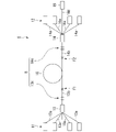
- FIG. 1 is a diagram showing a main configuration of a fiber laser device according to the first embodiment of the present invention.
- the fiber laser apparatus 1 of the present embodiment includes an excitation light source 11 (first excitation light source), an excitation light source 12 (second excitation light source), a combiner 13 (first coupler), and a combiner 14 (second excitation light source). It includes a coupler), an amplification fiber 15, and an output end 16.
- Such a fiber laser device 1 is a so-called bidirectional excitation type fiber laser device.
- the excitation light source 11 side may be referred to as "front” and the output end 16 side may be referred to as "rear” when viewed from the amplification fiber 15.
- fusion splicing portions of various fibers are indicated by x marks.
- This fusion splicing portion is actually arranged and protected inside a reinforcing portion (not shown).
- the reinforcing portion fixes, for example, a fiber accommodating body having a groove capable of accommodating an optical fiber and various fibers to the fiber accommodating body in a state where the fusion splicing portion is accommodated in the groove of the fiber accommodating body. It is configured with a resin.
- the excitation light source 11 outputs excitation light (first excitation light) having a wavelength ⁇ 1 (first wavelength).
- the wavelength ⁇ 1 is the peak wavelength of the excitation light output from the excitation light source 11.
- the excitation light source 11 is provided for forward-exciting the amplification fiber 15. Although four excitation light sources 11 are shown in FIG. 1, the number of excitation light sources 11 is arbitrary depending on the power of the laser light (signal light) output from the output end 16 of the fiber laser apparatus 1. be able to.
- the excitation light source 11 for example, a laser diode can be used. Details of the wavelength ⁇ 1 and the power of the excitation light output from the excitation light source 11 will be described later.
- the excitation light source 12 outputs excitation light (second excitation light) having a wavelength ⁇ 2 (second wavelength).
- the wavelength ⁇ 2 is the peak wavelength of the excitation light output from the excitation light source 12.
- the excitation light source 12 is provided to excite the amplification fiber 15 backward. Although four excitation light sources 12 are shown in FIG. 1, the number of excitation light sources 12 can be any number depending on the power of the laser beam output from the output end 16 of the fiber laser apparatus 1.
- the excitation light source 12 for example, a laser diode can be used in the same manner as the excitation light source 11. Details of the wavelength ⁇ 2 and the power of the excitation light output from the excitation light source 12 will be described later.
- the combiner 13 couples the excitation light output by each of the excitation light sources 11 to the front end portion of the amplification fiber 15 (the first end of the amplification fiber 15). Specifically, the combiner 13 is optically coupled to a plurality of optical fibers 13a connected to each of the excitation light sources 11 and the plurality of optical fibers 13a, and the rear end thereof is the front of the amplification fiber 15. It is provided with one optical fiber 13b to be fused and connected to the end portion of the fiber.
- the fusion splicing portion between the optical fiber on which the HR-FBG 13c described later is formed and the amplification fiber 15 will be referred to as a “fusing connection portion F1”.
- the fusion splicing portion between the optical fiber 13b and the amplification fiber 15 is referred to as a “fusing connection portion F1”.
- An HR-FBG (High Reflectivity-Fiber Bragg Grating) 13c is formed in the core of the optical fiber 13b.
- the HR-FBG 13c is adjusted so as to reflect light having a wavelength ⁇ 0 of signal light with a reflectance of almost 100% among the light emitted by the active element of the excited fiber 15 for amplification.
- the HR-FBG13c has a structure in which a portion having a high refractive index is repeated at a constant cycle along the longitudinal direction thereof.
- the combiner 14 couples the excitation light output by each of the excitation light sources 12 to the rear end of the amplification fiber 15 (the second end of the amplification fiber 15), and a part of the signal light is connected to the output end 16.
- the combiner 14 is optically coupled to a plurality of optical fibers 14a connected to each of the excitation light sources 12 and the plurality of optical fibers 14a, and the front end thereof is the rear side of the amplification fiber 15. It is provided with one optical fiber 14b to be fused and connected to the end of the fiber.
- the combiner 14 includes a delivery fiber 14d that is optically coupled to the optical fiber 14b.
- fusion-bonded connection portion F2 the fusion-bonded connection portion between the optical fiber on which the OC-FBG 14c, which will be described later, is formed and the amplification fiber 15, will be referred to as “fusion-bonded connection portion F2”.
- fusion-bonded connection portion F2 the fusion splicing portion between the optical fiber 14b and the amplification fiber 15 is referred to as a “fusing connection portion F2”.
- OC-FBG Output Coupler-Fiber Bragg Grating
- OC-FBG14c has almost the same structure as HR-FBG13c, but is adjusted to reflect light with a lower reflectance than HR-FBG13c.
- the OC-FBG14c is adjusted so that the reflectance of the signal light with respect to the light having the wavelength ⁇ 0 is about 10 to 20%.
- the delivery fiber 14d transmits a part of the signal light amplified in the amplification fiber 15.
- the delivery fiber 14d includes a core, a clad surrounding the core, and a coating covering the clad.
- a single mode fiber can be used as the delivery fiber 14d.
- the delivery fiber 14d may be, for example, a multimode fiber or a fumode fiber.
- the amplification fiber 15 has a core to which one or more kinds of active elements are added, a first clad covering the core, a second clad covering the first clad, and a protective coating covering the second clad. .. That is, the amplification fiber 15 is a double clad fiber.
- the active element added to the core for example, a rare earth element such as erbium (Er), ytterbium (Yb), or neodymium (Nd) is used.
- the active element added to the core of the amplification fiber 15 is excited by the excitation light output from the excitation light sources 11 and 12.
- Silica glass or the like can be used as the core and the first clad.
- a resin such as a polymer can be used.
- a resin material such as an acrylic resin or a silicone resin can be used.
- the amplification fiber 15 is a so-called fumode fiber or multimode fiber, and can propagate a plurality of modes. The number of modes propagated by the fumode fiber is, for example, 2 or more and 25 or less.
- the front end of the amplification fiber 15 is fusion-bonded to the rear end of the optical fiber 13b, and the rear end of the amplification fiber 15 is connected to the front end of the optical fiber 14b. ..
- the HR-FBG13c formed on the optical fiber 13b, the OC-FBG14c formed on the optical fiber 14b, and the amplification fiber 15 constitute the resonator R.
- the resonator R resonates the light emitted from the active element excited by the excitation light output by the excitation light sources 11 and 12, and generates a signal light which is a laser beam.
- the signal light reflected by the HR-FBG13c and OC-FBG14c reciprocates in the longitudinal direction of the amplification fiber 15.
- the signal light is amplified along with this round trip to become laser light.
- the resonator R the light is amplified and a signal light (laser light) is generated.
- the output end 16 is connected to the rear end of the delivery fiber 14d, and outputs the laser beam transmitted by the delivery fiber 14d to the outside.
- the output end 16 includes a columnar body (light transmitting columnar member) that transmits the laser beam transmitted by the delivery fiber 14d. This member is a so-called end cap.
- FIG. 2 is a diagram showing an example of an absorption spectrum of an active element added to an amplification fiber in the first embodiment of the present invention.
- the absorption spectrum exemplified in FIG. 2 is the absorption spectrum of ytterbium (Yb).
- Yb ytterbium
- large absorption peaks appear near the wavelength of 975 nm and the wavelength of 915 nm.
- the absorption peak appearing near the wavelength of 975 nm has the highest absorption rate, and the absorption peak appearing near the wavelength of 915 nm has a smaller absorption rate than the absorption peak appearing near the wavelength of 975 nm.
- the resonance wavelength of the resonator R is set to, for example, about 1060 to 1080 nm. That is, in the present embodiment, the wavelength ⁇ 0 of the signal light (laser light) output to the outside from the output end 16 of the fiber laser device 1 is set to about 1060 to 1080 nm. As shown in FIG. 2, the wavelength ⁇ 0 of the signal light is, for example, 1070 nm, which is a wavelength that is hardly absorbed by ytterbium (Yb), which is an active element added to the amplification fiber 15.
- Yb ytterbium
- the wavelength ⁇ 1 of the excitation light output from the excitation light source 11 and the wavelength ⁇ 2 of the excitation light output from the excitation light source 12 are set so as to satisfy the following equations (1) and (2). There is.
- the wavelengths ⁇ 1 and ⁇ 2 are set so that the absorption rate ⁇ ( ⁇ 1) of the active element at the wavelength ⁇ 1 is lower than the absorption rate ⁇ ( ⁇ 2) of the active element at the wavelength ⁇ 2.
- the wavelengths ⁇ 1 and ⁇ 2 are set shorter than the wavelength ⁇ 0 of the signal light, and the wavelength ⁇ 1 is set longer than the wavelength ⁇ 2. The reason for setting in this way is to suppress deterioration of beam quality due to the TMI phenomenon.
- the absorption rate of the excitation light per unit length near the fusion splicer F1 of the amplification fiber 15 is measured by the unit length near the fusion splicer F2 of the amplification fiber 15. It can be lower than the absorption rate of the excitation light at the moment.
- the temperature rise near the fusion splicer F1 of the amplification fiber 15 is suppressed, and the coupling between the modes from the basic mode to the higher-order mode can be prevented, so that the deterioration of the beam quality due to the TMI phenomenon is suppressed. be able to.
- the wavelengths ⁇ 1 and ⁇ 2 are set shorter than the wavelength ⁇ 0 of the signal light because the excitation light (wavelength) having a higher energy than the signal light is obtained in order to obtain the signal light having the wavelength ⁇ 0. This is because the excitation light of ⁇ 1 and ⁇ 2) is required. Further, in the above equation (2), the wavelength ⁇ 1 is set longer than the wavelength ⁇ 2 by bringing the wavelength ⁇ 1 closer to the wavelength ⁇ 0 of the signal light, so that the wavelength ⁇ 1 is near the fusion splicer F1 of the amplification fiber 15. This is to suppress the temperature rise due to quantum deficiency.
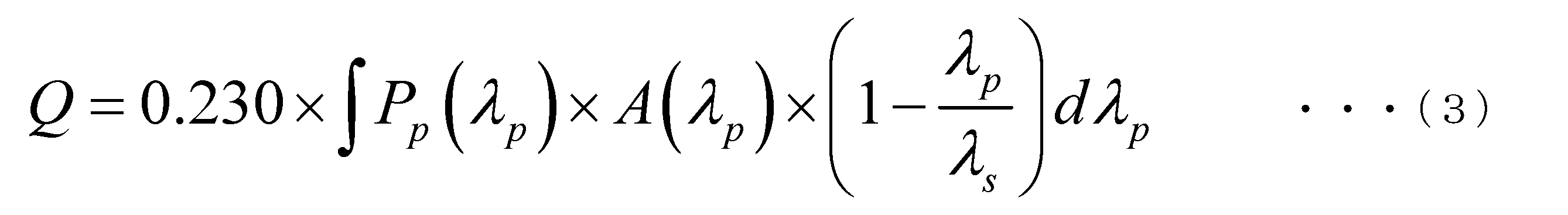
- the calorific value Q [W / m] per unit length in the amplification fiber 15 is expressed by the following equation (3).
- P p ( ⁇ p ) is the power spectrum [W] of the excitation light
- a ( ⁇ p ) is the spectrum of the absorption amount of the excitation light per unit length of the amplification fiber 15. It is [dB / m].
- ⁇ p is the wavelength [nm] of the excitation light
- ⁇ s is the wavelength [nm] of the signal light.
- the coefficient 0.230 on the right side is 0.1 ⁇ ln (10), which is a conversion coefficient from [dB] to linear.
- the calorific value Q per unit length in the amplification fiber 15 is proportional to the power of the excitation light and the absorption amount (absorption rate) per unit length.
- the portion (1- ⁇ p / ⁇ s ) on the right side of the above equation (3) is a term caused by a quantum defect. Since there is a relationship of ⁇ p ⁇ s , the longer the wavelength of ⁇ p , the smaller the amount of heat generated due to quantum deficiency.
- the wavelength ⁇ 1 is set longer than the wavelength ⁇ 2, and the wavelength ⁇ 1 is brought closer to the wavelength ⁇ 0 of the signal light, so that the temperature rise due to the quantum defect near the fusion splicer F1 of the amplification fiber 15 is increased. I try to suppress it.
- the wavelengths ⁇ 1 and ⁇ 2 of the excitation light satisfy any of the following relationships (A) to (C) while satisfying the relationships of the above equations (1) and (2).
- the wavelength ⁇ 2 coincides with the wavelength ⁇ P having the highest absorption rate of the active element.
- the wavelength ⁇ P having the highest absorption rate of the active element is between the wavelength ⁇ 1 and the wavelength ⁇ 2.
- the wavelengths ⁇ 1 and ⁇ 2 are on the longer wavelength side than the wavelength ⁇ P having the highest absorption rate of the active element.
- the wavelength ⁇ 2 of the excitation light output from the excitation light source 12 coincides with the wavelength ⁇ P having the highest absorption rate of the active element. Therefore, it is possible to efficiently absorb the excitation light output from the excitation light source 12 while suppressing the temperature rise in the vicinity of the fusion splicer F1 of the amplification fiber 15.
- the wavelength ⁇ P having the highest absorption rate of the active element is around 975 nm.
- the wavelength ⁇ 2 of the excitation light output from the excitation light source 12 is set to around 975 nm.
- the above-mentioned "matching" means that the difference between the wavelength ⁇ 2 and the wavelength ⁇ P is within ⁇ 1 nm.
- the light is output from the excitation light sources 11 and 12 while suppressing the temperature rise in the vicinity of the fusion splicer F2 in addition to the vicinity of the fusion splicer F1 of the amplification fiber 15. Can efficiently absorb the excitation light.
- the wavelength ⁇ 1 of the excitation light output from the excitation light source 11 is set to around 978 nm, and the excitation light output from the excitation light source 12 is set.
- the wavelength ⁇ 2 of is set to around 973 nm. Please note that the specific wavelengths listed here are just examples.
- the absorption rate of the excitation light output from the excitation light sources 11 and 12 can be lowered as compared with the case where the above relationship (A) is satisfied. Further, the wavelengths ⁇ 1 and ⁇ 2 of the excitation light output from the excitation light sources 11 and 12 can be made closer to the wavelength ⁇ 0 of the signal light. Therefore, it is possible to suppress the temperature rise in the vicinity of the fusion spliced portions F1 and F2 of the amplification fiber 15 as compared with the case where the above relationship (A) is satisfied. In the example shown in FIG.
- the wavelength ⁇ 1 of the excitation light output from the excitation light source 11 is set to around 985 nm, and the excitation light output from the excitation light source 12 is set.
- the wavelength ⁇ 2 of is set to around 980 nm. Please note that the specific wavelengths listed here are just examples.
- the difference between the wavelength ⁇ 1 of the excitation light output from the excitation light source 11 and the wavelength ⁇ 2 of the excitation light output from the excitation light source 12 is 1 nm or more and 5 nm or less.
- the length of the amplification fiber 15 is set to a length at which the excitation light having a wavelength ⁇ 1 having a low absorption rate is sufficiently absorbed (for example, 95% is absorbed).
- the difference between the wavelengths ⁇ 1 and ⁇ 2 is 1 nm or more and 5 nm or less, the absorption rate of the excitation light of the wavelength ⁇ 1 is not extremely lower than the absorption rate of the excitation light of the wavelength ⁇ 2, so that the absorption rate is low.
- the excitation light having the wavelength ⁇ 1 is supplied to the amplification fiber 15 from the front end side of the amplification fiber 15 (the optical fiber having the active element added to the core), and the wavelength ⁇ 2 is set.
- the excitation light is supplied to the amplification fiber 15 from the rear end side of the amplification fiber 15.
- the absorption rate of the active element at the wavelength ⁇ 1 is lower than the absorption rate of the active element at the wavelength ⁇ 2
- the wavelengths ⁇ 1 and ⁇ 2 are set shorter than the wavelength ⁇ 0 of the signal light
- the wavelength ⁇ 1 is set longer than the wavelength ⁇ 2. ing.
- the absorption rate of the excitation light per unit length near the fusion splicer F1 of the amplification fiber 15 is calculated from the absorption rate of the excitation light per unit length near the fusion splicer F2 of the amplification fiber 15. Can also be lowered. As a result, the temperature rise near the fusion splicer F1 of the amplification fiber 15 is suppressed, and the coupling between the modes from the basic mode to the higher-order mode can be prevented, so that the deterioration of the beam quality due to the TMI phenomenon is suppressed. be able to.
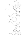
- the fiber laser apparatus of this embodiment has a different method of supplying excitation light to the amplification fiber 15.
- the fiber laser apparatus 1 according to the first embodiment described above supplies the excitation light output from the excitation light sources 11 and 12 to the amplification fiber 15 by the combiners 13 and 14, respectively.
- the fiber laser apparatus of the present embodiment is different in that the excitation light is supplied by the side pump.
- the side pump is a partially contacted or partially fused connection between the clad of the supply fiber to which the excitation light is supplied and the clad of the supplied fiber to which the excitation light is to be supplied. In this method, the excitation light supplied to the supply fiber is supplied to the supplied fiber via the contact portion.
- the combiners 13 and 14 shown in FIG. 1 are omitted.
- the excitation light (excitation light having a wavelength ⁇ 1) output from the excitation light source 11 is supplied by the side pump (first coupler), for example, between the HR-FBG13c and the fusion splicer F1.
- the excitation light (excitation light having a wavelength ⁇ 2) output from the excitation light source 12 is supplied by a side pump (second coupler), for example, between the OC-FBG14c and the fusion splicer F2.
- the excitation light of the wavelength ⁇ 1 output from the excitation light source 11 is the amplification fiber 15 from the first end side (fusion connection portion F1 side) of the amplification fiber 15. Is supplied to. Further, the excitation light having a wavelength ⁇ 2 output from the excitation light source 12 is supplied to the amplification fiber 15 from the second end side (fusion connection portion F2 side) of the amplification fiber 15.
- the wavelengths ⁇ 1 and ⁇ 2 of the excitation light satisfy any of the above-mentioned relationships (A) to (C) while satisfying the above-mentioned relationships of the above equations (1) and (2). Be made to meet. Therefore, also in this embodiment, the temperature rise in the vicinity of the fusion splicer F1 of the amplification fiber 15 is suppressed, and the coupling between the modes from the basic mode to the higher-order mode can be prevented, so that the beam due to the TMI phenomenon can be prevented. Deterioration of quality can be suppressed.
- the fiber laser apparatus of this embodiment is different from the optical fiber in which the HR-FBG13c and the OC-FBG14c are formed.
- the HR-FBG13c is formed in the core of the optical fiber 13b provided in the combiner 13
- the OC-FBG14c is formed in the core of the optical fiber 14b provided in the combiner 14.
- the HR-FBG 13c is formed in the core of the optical fiber 13d different from the optical fiber 13b provided in the combiner 13, and is different from the optical fiber 14b provided in the combiner 14.
- OC-FBG14c is formed in the core of the optical fiber 14e of the above.
- the fusion splicing portion between the optical fiber 13d and the amplification fiber 15 is referred to as "fused connection portion F1"
- the fusion splicing portion between the optical fiber 14e and the amplification fiber 15 is referred to as “fusion connection portion”. It is called "F2”.
- the front end of the optical fiber 13d on which the HR-FBG 13c is formed is connected to the optical fiber 13b of the combiner 13, and the rear end is connected to the front end of the amplification fiber 15.
- the front end is connected to the rear end of the amplification fiber 15, and the rear end is connected to the optical fiber 14b of the combiner 14.
- a fusion splicing portion F3 is formed between the optical fiber 13b and the HR-FBG 13c, and the fusion splicing portion F3 is fused between the optical fiber 14b and the OC-FBG 14c.
- the connection portion F4 is formed.
- the wavelengths ⁇ 1 and ⁇ 2 of the excitation light satisfy any of the above-mentioned relationships (1) and (2) while satisfying any of the above-mentioned relationships (A) to (C). Be made to meet. Therefore, also in this embodiment, the temperature rise in the vicinity of the fusion splicer F1 of the amplification fiber 15 is suppressed, and the coupling between the modes from the basic mode to the higher-order mode can be prevented, so that the beam due to the TMI phenomenon can be prevented. Deterioration of quality can be suppressed.
- the present invention is not limited to the above embodiments and can be freely changed within the scope of the present invention.
- the excitation light that excites the amplification fiber 15 forward (the excitation light coupled to the amplification fiber 15 from the first end side) and the excitation light that excites the rearward (excitation coupled to the amplification fiber 15 from the second end side).
- Light may include wavelengths ⁇ 1 and ⁇ 2.
- some of the four excitation light sources 11 for example, one
- some of the four excitation light sources 12 for example, one
- the amplification fiber 15 is excited forward by the excitation light including the wavelengths ⁇ 1 and ⁇ 2
- the amplification fiber 15 is excited backward by the excitation light including the wavelengths ⁇ 1 and ⁇ 2.
- the calorific value in the vicinity of the fusion splicer F1 of the amplification fiber 15 becomes smaller than the calorific value in the vicinity of the fusion splicer F2.
- the temperature rise near the fusion splicer F1 of the amplification fiber 15 is suppressed, and the coupling between the modes from the basic mode to the higher-order mode can be prevented, so that the deterioration of the beam quality due to the TMI phenomenon is suppressed. be able to.
- the fiber laser devices 1 and 1A of the above-described embodiment have a configuration having one output end 16, an optical fiber or the like may be further connected to the tip of the output end 16. Further, a beam combiner may be connected to the tip of the output end 16 so as to bundle laser light from a plurality of laser devices.
- 1,1A ... Fiber laser device, 11 ... Excitation light source, 12 ... Excitation light source, 13 ... Combiner, 13c ... HR-FBG, 14 ... Combiner, 14c ... OC-FBG, 15 ... Amplification fiber, 16 ... Output end
Landscapes
- Physics & Mathematics (AREA)
- Electromagnetism (AREA)
- Engineering & Computer Science (AREA)
- Plasma & Fusion (AREA)
- Optics & Photonics (AREA)
- Lasers (AREA)
Abstract
Description
本願は、2020年9月24日に日本に出願された特願2020-159746号について優先権を主張し、その内容をここに援用する。
図1は、本発明の第1実施形態によるファイバレーザ装置の要部構成を示す図である。図1に示す通り、本実施形態のファイバレーザ装置1は、励起光源11(第1励起光源)、励起光源12(第2励起光源)、コンバイナ13(第1結合器)、コンバイナ14(第2結合器)、増幅用ファイバ15、及び出力端16を備える。このようなファイバレーザ装置1は、いわゆる双方向励起型のファイバレーザ装置である。

(A)波長λ2が、活性元素の吸収率が最も高い波長λPと一致する。
(B)活性元素の吸収率が最も高い波長λPが、波長λ1と波長λ2との間にある。
(C)波長λ1,λ2は、活性元素の吸収率が最も高い波長λPよりも長波長側にある。
次に、本発明の第2実施形態によるファイバレーザ装置について説明する。本実施形態のファイバレーザ装置は、増幅用ファイバ15に対する励起光の供給方法が異なる。上述した第1実施形態によるファイバレーザ装置1は、励起光源11,12から出力される励起光をそれぞれ、コンバイナ13,14によって増幅用ファイバ15に供給している。これに対し、本実施形態のファイバレーザ装置は、サイドポンプにより励起光を供給する点が異なる。ここで、サイドポンプとは、励起光が供給される供給用ファイバのクラッドと、励起光を供給すべき被供給用ファイバのクラッドとの側面を部分的に接触させ、或いは部分的に融着接続し、供給用ファイバに供給される励起光を、接触部を介して被供給用ファイバに供給する方式である。
次に、本発明の第3実施形態によるファイバレーザ装置について説明する。本実施形態のファイバレーザ装置は、HR-FBG13c及びOC-FBG14cが形成されている光ファイバが異なる。前述した第1実施形態では、コンバイナ13に設けられた光ファイバ13bのコアにHR-FBG13cが形成されており、コンバイナ14に設けられた光ファイバ14bのコアにOC-FBG14cが形成されていた。
本実施形態のファイバレーザ装置1Aは、コンバイナ13に設けられた光ファイバ13bとは別の光ファイバ13dのコアにHR-FBG13cが形成されており、コンバイナ14に設けられた光ファイバ14bとは別の光ファイバ14eのコアにOC-FBG14cが形成されている。
本実施形態では、光ファイバ13dと増幅用ファイバ15との融着接続部を「融着接続部F1」と称し、光ファイバ14eと増幅用ファイバ15との融着接続部を「融着接続部F2」と称する。
(a)増幅用ファイバ15を前方励起する励起光と増幅用ファイバ15を後方励起する励起光とのパワーが同じ場合に、増幅用ファイバ15の融着接続部F1付近における発熱量が、融着接続部F2付近における発熱量より小さい。
(b)増幅用ファイバ15を前方励起する励起光のパワーが、増幅用ファイバ15を後方励起する励起光のパワーより小さい。
Claims (7)
- 第1波長の第1励起光を出力する第1励起光源と、
前記第1波長とは異なる第2波長の第2励起光を出力する第2励起光源と、
前記第1励起光及び前記第2励起光により励起される活性元素が添加されたコアを有する増幅用ファイバと、
前記増幅用ファイバの第一端側に設けられたHR-FBGと、
前記増幅用ファイバの第二端側に設けられ、前記HR-FBGよりも反射率が小さいOC-FBGと、
前記第1励起光を、前記第一端側から前記増幅用ファイバに結合させる第1結合器と、
前記第2励起光を、前記第二端側から前記増幅用ファイバに結合させる第2結合器と、
前記増幅用ファイバで増幅されて前記OC-FBGを介したレーザ光を出力する出力端と、
を備え、
前記活性元素の前記第1波長における吸収率は、前記活性元素の前記第2波長における吸収率より低く、
前記第1波長及び前記第2波長は、前記レーザ光の波長よりも短く、
前記第1波長は、前記第2波長より長い、
ファイバレーザ装置。 - 前記第2波長は、前記活性元素の吸収率が最も高い波長と一致する、請求項1記載のファイバレーザ装置。
- 前記活性元素の吸収率が最も高い波長は、前記第1波長と前記第2波長との間の波長である、請求項1記載のファイバレーザ装置。
- 前記第1波長及び前記第2波長は、前記活性元素の吸収率が最も高い波長よりも長波長側の波長である、請求項1記載のファイバレーザ装置。
- 前記第1波長と前記第2波長との差は、1nm以上5nm以下である、請求項1から請求項4の何れか一項に記載のファイバレーザ装置。
- 前記第一端側から前記増幅用ファイバに結合される励起光のパワーと前記第二端側から前記増幅用ファイバに結合される励起光のパワーとが同じ場合に、前記増幅用ファイバの前記第一端における発熱量は、前記増幅用ファイバの前記第二端における発熱量より小さい、請求項1から請求項5の何れか一項に記載のファイバレーザ装置。
- 前記第一端側から前記増幅用ファイバに結合される励起光のパワーは、前記第二端側から前記増幅用ファイバに結合される励起光のパワーより小さい、請求項1から請求項5の何れか一項に記載のファイバレーザ装置。
Priority Applications (4)
| Application Number | Priority Date | Filing Date | Title |
|---|---|---|---|
| CN202180059699.7A CN116157968A (zh) | 2020-09-24 | 2021-07-27 | 光纤激光装置 |
| US18/006,263 US20240014623A1 (en) | 2020-09-24 | 2021-07-27 | Fiber laser device |
| JP2022551163A JP7355945B2 (ja) | 2020-09-24 | 2021-07-27 | ファイバレーザ装置 |
| EP21871964.9A EP4220872A1 (en) | 2020-09-24 | 2021-07-27 | Fiber laser device |
Applications Claiming Priority (2)
| Application Number | Priority Date | Filing Date | Title |
|---|---|---|---|
| JP2020-159746 | 2020-09-24 | ||
| JP2020159746 | 2020-09-24 |
Publications (1)
| Publication Number | Publication Date |
|---|---|
| WO2022064832A1 true WO2022064832A1 (ja) | 2022-03-31 |
Family
ID=80845254
Family Applications (1)
| Application Number | Title | Priority Date | Filing Date |
|---|---|---|---|
| PCT/JP2021/027692 WO2022064832A1 (ja) | 2020-09-24 | 2021-07-27 | ファイバレーザ装置 |
Country Status (5)
| Country | Link |
|---|---|
| US (1) | US20240014623A1 (ja) |
| EP (1) | EP4220872A1 (ja) |
| JP (1) | JP7355945B2 (ja) |
| CN (1) | CN116157968A (ja) |
| WO (1) | WO2022064832A1 (ja) |
Citations (9)
| Publication number | Priority date | Publication date | Assignee | Title |
|---|---|---|---|---|
| JPH08307000A (ja) * | 1995-03-06 | 1996-11-22 | Matsushita Electric Ind Co Ltd | 希土類イオン添加短波長レーザ装置、希土類イオン添加光増幅器及び希土類イオン添加波長変換器 |
| JP2006245334A (ja) * | 2005-03-03 | 2006-09-14 | Nippon Telegr & Teleph Corp <Ntt> | 光ファイバ増幅器 |
| JP2007318013A (ja) * | 2006-05-29 | 2007-12-06 | Sumitomo Electric Ind Ltd | 光増幅器および光伝送システム |
| CN102801091A (zh) * | 2012-09-06 | 2012-11-28 | 北京化工大学 | 随机光纤激光器 |
| US20150372442A1 (en) * | 2014-01-31 | 2015-12-24 | Ofs Fitel, Llc | Architecture for high power fiber laser |
| JP2018041792A (ja) | 2016-09-06 | 2018-03-15 | 株式会社フジクラ | ファイバレーザ |
| JP2018125406A (ja) * | 2017-01-31 | 2018-08-09 | 株式会社フジクラ | ファイバレーザ、供給方法、及び製造方法 |
| JP6731099B1 (ja) * | 2019-07-25 | 2020-07-29 | 株式会社フジクラ | ファイバレーザ、及び、レーザ光の出力方法 |
| JP2020159746A (ja) | 2019-03-25 | 2020-10-01 | 株式会社Jvcケンウッド | ナビゲーション制御装置、ナビゲーションシステム、ナビゲーション方法およびプログラム |
Family Cites Families (1)
| Publication number | Priority date | Publication date | Assignee | Title |
|---|---|---|---|---|
| WO2011115275A1 (ja) | 2010-03-19 | 2011-09-22 | 株式会社フジクラ | 光ファイバ増幅器、及び、それを用いたファイバレーザ装置 |
-
2021
- 2021-07-27 CN CN202180059699.7A patent/CN116157968A/zh active Pending
- 2021-07-27 EP EP21871964.9A patent/EP4220872A1/en active Pending
- 2021-07-27 JP JP2022551163A patent/JP7355945B2/ja active Active
- 2021-07-27 WO PCT/JP2021/027692 patent/WO2022064832A1/ja active Application Filing
- 2021-07-27 US US18/006,263 patent/US20240014623A1/en active Pending
Patent Citations (9)
| Publication number | Priority date | Publication date | Assignee | Title |
|---|---|---|---|---|
| JPH08307000A (ja) * | 1995-03-06 | 1996-11-22 | Matsushita Electric Ind Co Ltd | 希土類イオン添加短波長レーザ装置、希土類イオン添加光増幅器及び希土類イオン添加波長変換器 |
| JP2006245334A (ja) * | 2005-03-03 | 2006-09-14 | Nippon Telegr & Teleph Corp <Ntt> | 光ファイバ増幅器 |
| JP2007318013A (ja) * | 2006-05-29 | 2007-12-06 | Sumitomo Electric Ind Ltd | 光増幅器および光伝送システム |
| CN102801091A (zh) * | 2012-09-06 | 2012-11-28 | 北京化工大学 | 随机光纤激光器 |
| US20150372442A1 (en) * | 2014-01-31 | 2015-12-24 | Ofs Fitel, Llc | Architecture for high power fiber laser |
| JP2018041792A (ja) | 2016-09-06 | 2018-03-15 | 株式会社フジクラ | ファイバレーザ |
| JP2018125406A (ja) * | 2017-01-31 | 2018-08-09 | 株式会社フジクラ | ファイバレーザ、供給方法、及び製造方法 |
| JP2020159746A (ja) | 2019-03-25 | 2020-10-01 | 株式会社Jvcケンウッド | ナビゲーション制御装置、ナビゲーションシステム、ナビゲーション方法およびプログラム |
| JP6731099B1 (ja) * | 2019-07-25 | 2020-07-29 | 株式会社フジクラ | ファイバレーザ、及び、レーザ光の出力方法 |
Also Published As
| Publication number | Publication date |
|---|---|
| JP7355945B2 (ja) | 2023-10-03 |
| US20240014623A1 (en) | 2024-01-11 |
| EP4220872A1 (en) | 2023-08-02 |
| CN116157968A (zh) | 2023-05-23 |
| JPWO2022064832A1 (ja) | 2022-03-31 |
Similar Documents
| Publication | Publication Date | Title |
|---|---|---|
| US7046432B2 (en) | Optical fiber coupling arrangement | |
| JP6007238B2 (ja) | ファイバレーザ装置およびレーザ光照射位置の位置決め方法 | |
| JP5260885B2 (ja) | 光ファイバの漏洩光処理構造 | |
| EP2477284B1 (en) | Light combiner and fiber laser device using same | |
| CN110418992B (zh) | 包层模光除去构造和激光装置 | |
| US20110235165A1 (en) | Amplification optical fiber with optical component and fiber laser device including the same | |
| US20150247972A1 (en) | Optical fiber, fiber laser, and optical fiber manufacturing method | |
| JP5378861B2 (ja) | 光ファイバレーザ | |
| JP6734683B2 (ja) | 光モニタ装置及びレーザ装置 | |
| JP2009069492A (ja) | 光ファイバおよび光学装置 | |
| CN110364919B (zh) | 光纤激光装置 | |
| JP5335613B2 (ja) | レーザ装置 | |
| WO2022064832A1 (ja) | ファイバレーザ装置 | |
| WO2019131971A1 (ja) | 光ファイバ、及び、レーザ装置 | |
| CN108603983B (zh) | 光学模块及光输出装置 | |
| JP7300512B2 (ja) | 光増幅装置 | |
| WO2020171152A1 (ja) | 光デバイス及びレーザ装置 | |
| US7724424B2 (en) | Optical module and optical amplification module | |
| JP4899705B2 (ja) | 光増幅モジュール | |
| JP2021136242A (ja) | ファイバレーザ装置 | |
| WO2021240910A1 (ja) | 光ファイバ接続体及びファイバレーザ装置 | |
| JP7136996B2 (ja) | ファイバレーザ装置 | |
| JP2022114272A (ja) | 光デバイス及びレーザ装置 | |
| JP2007294534A (ja) | 光学的モジュール | |
| WO2020045569A1 (ja) | クラッドモード光除去構造、レーザ装置、及びクラッドモード光除去構造の製造方法 |
Legal Events
| Date | Code | Title | Description |
|---|---|---|---|
| 121 | Ep: the epo has been informed by wipo that ep was designated in this application |
Ref document number: 21871964 Country of ref document: EP Kind code of ref document: A1 |
|
| ENP | Entry into the national phase |
Ref document number: 2022551163 Country of ref document: JP Kind code of ref document: A |
|
| WWE | Wipo information: entry into national phase |
Ref document number: 18006263 Country of ref document: US |
|
| NENP | Non-entry into the national phase |
Ref country code: DE |
|
| ENP | Entry into the national phase |
Ref document number: 2021871964 Country of ref document: EP Effective date: 20230424 |