WO2022064792A1 - ウェビング巻取装置 - Google Patents
ウェビング巻取装置 Download PDFInfo
- Publication number
- WO2022064792A1 WO2022064792A1 PCT/JP2021/023119 JP2021023119W WO2022064792A1 WO 2022064792 A1 WO2022064792 A1 WO 2022064792A1 JP 2021023119 W JP2021023119 W JP 2021023119W WO 2022064792 A1 WO2022064792 A1 WO 2022064792A1
- Authority
- WO
- WIPO (PCT)
- Prior art keywords
- cylinder
- moving member
- axial
- axial direction
- winding device
- Prior art date
- Legal status (The legal status is an assumption and is not a legal conclusion. Google has not performed a legal analysis and makes no representation as to the accuracy of the status listed.)
- Ceased
Links
Images





Classifications
-
- B—PERFORMING OPERATIONS; TRANSPORTING
- B60—VEHICLES IN GENERAL
- B60R—VEHICLES, VEHICLE FITTINGS, OR VEHICLE PARTS, NOT OTHERWISE PROVIDED FOR
- B60R22/00—Safety belts or body harnesses in vehicles
- B60R22/34—Belt retractors, e.g. reels
- B60R22/46—Reels with means to tension the belt in an emergency by forced winding up
- B60R22/4628—Reels with means to tension the belt in an emergency by forced winding up characterised by fluid actuators, e.g. pyrotechnic gas generators
- B60R22/4633—Linear actuators, e.g. comprising a piston moving along reel axis and rotating along its own axis
-
- B—PERFORMING OPERATIONS; TRANSPORTING
- B60—VEHICLES IN GENERAL
- B60R—VEHICLES, VEHICLE FITTINGS, OR VEHICLE PARTS, NOT OTHERWISE PROVIDED FOR
- B60R22/00—Safety belts or body harnesses in vehicles
- B60R22/34—Belt retractors, e.g. reels
- B60R22/46—Reels with means to tension the belt in an emergency by forced winding up
-
- B—PERFORMING OPERATIONS; TRANSPORTING
- B60—VEHICLES IN GENERAL
- B60R—VEHICLES, VEHICLE FITTINGS, OR VEHICLE PARTS, NOT OTHERWISE PROVIDED FOR
- B60R22/00—Safety belts or body harnesses in vehicles
- B60R22/34—Belt retractors, e.g. reels
- B60R22/46—Reels with means to tension the belt in an emergency by forced winding up
- B60R22/4628—Reels with means to tension the belt in an emergency by forced winding up characterised by fluid actuators, e.g. pyrotechnic gas generators
-
- B—PERFORMING OPERATIONS; TRANSPORTING
- B60—VEHICLES IN GENERAL
- B60R—VEHICLES, VEHICLE FITTINGS, OR VEHICLE PARTS, NOT OTHERWISE PROVIDED FOR
- B60R22/00—Safety belts or body harnesses in vehicles
- B60R22/34—Belt retractors, e.g. reels
- B60R22/46—Reels with means to tension the belt in an emergency by forced winding up
- B60R22/4628—Reels with means to tension the belt in an emergency by forced winding up characterised by fluid actuators, e.g. pyrotechnic gas generators
- B60R2022/4642—Reels with means to tension the belt in an emergency by forced winding up characterised by fluid actuators, e.g. pyrotechnic gas generators the gas directly propelling a flexible driving means, e.g. a plurality of successive masses, in a tubular chamber
-
- B—PERFORMING OPERATIONS; TRANSPORTING
- B60—VEHICLES IN GENERAL
- B60R—VEHICLES, VEHICLE FITTINGS, OR VEHICLE PARTS, NOT OTHERWISE PROVIDED FOR
- B60R22/00—Safety belts or body harnesses in vehicles
- B60R22/34—Belt retractors, e.g. reels
- B60R22/46—Reels with means to tension the belt in an emergency by forced winding up
- B60R2022/468—Reels with means to tension the belt in an emergency by forced winding up characterised by clutching means between actuator and belt reel
Definitions
- the present invention relates to a webbing winding device in which a spool is rotated in a winding direction by rotating a rotating member.
- the webbing winder disclosed in International Publication No. 2012/143090 includes a tube appropriately bent along the frame.
- a drive unit is provided at the axial base end of the tube, and a flexible rod-shaped force transmitting member is arranged inside the tube.
- gas is supplied to the inside of the tube.
- the pressure of this gas moves the force transmission member toward the axial tip side of the tube.
- a pinion is located outside the axial tip of the tube.
- the pinion is connected to the spool, and when the force transmitting member moved toward the axial tip side of the tube by the pressure of the gas goes out of the tube, the force transmitting member is engaged with the pinion to rotate the pinion. In this way, when the pinion is rotated, the spool is rotated in the winding direction and the webbing is wound.
- the force transmission member arranged inside such a tube expands and contracts with changes in temperature and humidity. If the axial proximal end side of the force transmitting member is arranged at the curved portion of the tube, the end portion of the axial proximal end side interferes with the curved portion of the tube and the force transmitting member extends toward the axial tip side. By repeating expansion and contraction, the axial tip side of the force transmitting member moves to the pinion side. Therefore, it is necessary to arrange the force transmission member with a margin so that the axial tip does not come into contact with the pinion, and it is necessary to lengthen the total length of the tube or shorten the force transmission member.
- an object of the present invention is to obtain a webbing winding device capable of suppressing extension of a moving member on the axial tip side.
- a fluid supply unit provided on the axial base end side of the cylinder to supply fluid to the inside of the cylinder in an emergency of a vehicle, and a fluid supply unit provided on the inside of the cylinder to the axial tip side of the cylinder by the pressure of the fluid.
- the fluid supply unit is provided on the axial base end side of the cylinder, and when the fluid supply unit is operated in an emergency of the vehicle, the fluid is supplied to the inside of the cylinder. ..
- the moving member provided inside the cylinder is moved toward the tip side in the axial direction of the cylinder.
- the moving member engages with the tooth portion of the rotating member.
- the rotating member is rotated to one side.
- the spool is rotated in the winding direction, whereby the webbing of the seat belt device is wound on the spool.
- a curved portion is set at the axial base end portion of the cylinder, and a straight portion is set on the axial proximal end side of the curved portion.
- the portion of the moving member on the axial base end side of the cylinder is contained in the straight portion of the cylinder. Therefore, the portion of the moving member on the axial base end side of the cylinder is formed into a straight shape following the straight portion of the cylinder, and expands and contracts toward the axial base end side of the moving member due to changes in temperature and humidity. As a result, it is possible to suppress the extension of the moving member on the distal end side in the axial direction.
- the webbing winding device is the webbing winding device according to the first aspect, wherein the diameter of the cylinder in the moving member is orthogonal to the axial tip portion of the cylinder. It has a part with a large diameter.
- the axial base end portion of the cylinder in the moving member has a larger diameter in the axial direction than the axial tip portion of the cylinder in the moving member. .. Therefore, the axial base end of the cylinder of the moving member is unlikely to tilt due to changes in temperature and humidity. As a result, the axial base end of the cylinder of the moving member expands and contracts toward the axial base end of the moving member due to changes in temperature and humidity. As a result, it is possible to suppress the extension of the moving member on the distal end side in the axial direction.
- the webbing winding device is the webbing winding device according to the second aspect, wherein the axis of the moving member is intermittently provided in at least one of the axial direction and the circumferential direction in the outer peripheral portion of the moving member. A portion having a large diameter in the orthogonal direction is provided.
- a portion of the outer peripheral portion of the moving member whose radial dimension in the axial orthogonal direction is intermittently large in at least one of the axial direction and the circumferential direction. It is provided. Therefore, the portion other than the portion having the large diameter in the axial direction of the moving member has a smaller diameter than the portion having the large diameter in the axial orthogonal direction of the moving member. Therefore, when moving in the cylinder, the portion where the diameter of the moving member in the direction orthogonal to the axis is small is less likely to receive resistance from the cylinder.
- the webbing winding device is the webbing winding device according to the second or third aspect, wherein the diameter dimension in the direction orthogonal to the axis of the moving member is larger than that of the portion having a large diameter.
- the diameter dimension in the direction orthogonal to the axis of the moving member is larger than that of the portion having a large diameter.
- On the axial tip side of the moving member there is a portion having a smaller diameter dimension in the axial orthogonal direction than a portion having a large diameter dimension in the axial orthogonal direction of the moving member.
- the diameter dimension in the axial direction of the moving member is closer to the axial tip side of the moving member than the portion where the diameter dimension in the axial orthogonal direction of the moving member is large. It has a portion whose diameter dimension in the direction orthogonal to the axis is smaller than the portion having a large diameter. Stress is concentrated in the portion where the diameter dimension in the axis orthogonal direction is smaller than the portion where the diameter dimension in the axis orthogonal direction of the moving member is large, and it is easy to bend.
- a plurality of curved portions are formed on the cylinder along the axial direction of the cylinder. It is set.
- a plurality of curved portions are set in the cylinder along the axial direction of the cylinder. Therefore, the cylinder can be planar or three-dimensional, and the total length of the cylinder can be increased.
- three or more of the curved portions are set along the axial direction of the cylinder, and at least one of the above.
- the axial direction of the bend of the bend intersects the axial direction of the bend of at least one other said bend.
- the webbing winding device of the sixth aspect of the present invention three or more curved portions are set along the axial direction of the cylinder. Further, in this webbing winding device, the axial direction of bending of at least one curved portion intersects with the axial direction of bending of at least one other curved portion. Therefore, the cylinder becomes three-dimensional, and the total length of the cylinder can be increased.
- the webbing winding device is the webbing winding device according to any one of the first to sixth aspects, wherein the axial direction of the cylinder is set at the axial proximal end portion of the cylinder. Face inward in the width direction.
- the axial direction of the cylinder faces inward in the vehicle width direction at the axial base end portion of the cylinder.
- the inside of the center pillar opens inward in the vehicle width direction. Therefore, when the webbing winding device is provided in the center pillar, the axial base end of the cylinder faces inward in the vehicle width direction, so that the axial base end of the cylinder faces the opening side of the center pillar. become. Therefore, the fluid supply unit can be attached to the axial base end portion of the cylinder after the webbing winding device is assembled to the center pillar.
- the webbing winding device is provided at the axial base end portion of the moving member in the webbing winding device according to any one of the first to the seventh aspects, and is provided on the cylinder. It is annular in the axial direction and includes a sealing member that seals the gap between the cylinder and the moving member.
- the sealing member is provided on the moving member.
- the sealing member is annular in the axial direction of the cylinder and seals the gap between the cylinder and the moving member.
- the seal member is provided at the axial base end portion of the moving member. Therefore, the axial base end of the moving member can be brought closer to the fluid supply unit.
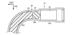
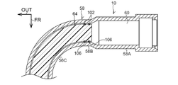
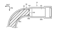
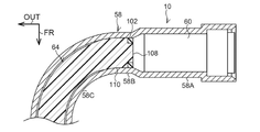
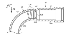
- FIG. 4 It is an exploded perspective view of the webbing winding apparatus which concerns on 1st Embodiment. It is sectional drawing which cut in the direction orthogonal to the vehicle front-rear direction. It is a side view which looked at the inside of a cover plate from the front side of a vehicle which shows the state which the moving member was in contact with a stopper. It is sectional drawing which shows the mounting part, the 1st straight part, and 1st bending part of a cylinder. It is sectional drawing corresponding to FIG. 4 which shows the 2nd Embodiment. It is sectional drawing corresponding to FIG. 4 which shows the 3rd Embodiment. It is sectional drawing corresponding to FIG. 4 which shows the 4th Embodiment.
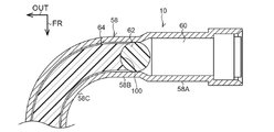
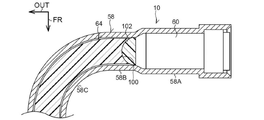
- FIG. 4 It is sectional drawing corresponding to FIG. 4 which shows the 5th Embodiment. It is sectional drawing corresponding to FIG. 4 which shows the 6th Embodiment. It is sectional drawing corresponding to FIG. 4 which shows the 7th Embodiment. It is sectional drawing corresponding to FIG. 4 which shows the 8th Embodiment. 9 is a cross-sectional view corresponding to FIG. 4 showing a ninth embodiment. It is sectional drawing corresponding to FIG. 4 which shows the tenth embodiment. It is sectional drawing corresponding to FIG. 4 which shows the eleventh embodiment.
- the arrow FR indicates the front side of the vehicle to which the webbing winding device 10 is applied
- the arrow OUT indicates the outside in the vehicle width direction
- the arrow UP indicates the upper side of the vehicle.
- the arrow A indicates the winding direction which is the rotation direction of the spool 18 when the spool 18 winds the webbing 20
- the arrow B indicates the drawing direction opposite to the winding direction.
- the webbing winding device 10 includes a frame 12.
- the frame 12 is fixed to the lower portion of the vehicle body of the center pillar (not shown) as the vehicle body.
- the frame 12 is provided with a spool 18.
- the spool 18 is formed in a substantially cylindrical shape, and is rotatable around the central axis (direction of arrow A and direction of arrow B in FIG. 1).
- a longitudinal base end portion of the long strip-shaped webbing 20 is locked to the spool 18, and when the spool 18 is rotated in the winding direction (direction of arrow A in FIG. 1), the webbing 20 is rotated in the longitudinal direction. It is wound on the spool 18 from the base end side.
- the distal end side of the webbing 20 extends from the spool 18 to the upper side of the vehicle, and passes through a slit hole formed in a through anchor (not shown) supported by the center pillar on the upper side of the vehicle of the frame 12 to the lower side of the vehicle. It has been turned back.
- the anchor plate is formed of a metal plate material such as iron, and is fixed to a vehicle floor (not shown) or a skeleton member of a sheet (not shown) corresponding to the webbing winding device 10.
- the seatbelt device for a vehicle to which the webbing take-up device 10 is applied is provided with a buckle device (not shown).
- the buckle device is provided inside the seat (not shown) to which the webbing winding device 10 is applied in the vehicle width direction.
- the webbing 20 is attached to the occupant's body by engaging the tongue (not shown) provided on the webbing 20 with the buckle device while the webbing 20 is hung around the occupant's body seated on the seat. ..
- a spring housing 22 is provided on the vehicle rear side of the frame 12. Inside the spring housing 22, a spool urging portion (not shown) such as a spring is provided. The spool urging portion is directly or indirectly engaged with the spool 18, and the spool 18 is urged in the winding direction (direction of arrow A in FIG. 1) by the urging force of the spool urging portion.
- the webbing winding device 10 is provided with a torsion bar 24 constituting a force limiter mechanism.
- the vehicle rear side portion of the torsion bar 24 is arranged inside the spool 18 and is connected to the spool 18 in a state where the relative rotation with respect to the spool 18 is restricted.
- the vehicle front side portion of the torsion bar 24 extends to the outside of the frame 12 (vehicle front side) through the hole formed in the frame 12.
- a rotating member 28 of the pretensioner 26 is provided on the vehicle front side of the frame 12.
- the rotating member 28 is arranged coaxially with the spool 18.
- the vehicle front side portion of the torsion bar 24 is connected to the rotating member 28, and the rotating member 28 is restricted from rotating relative to the vehicle front side portion of the torsion bar 24.
- the rotating member 28 includes a pair of flange portions 30 facing each other in the front-rear direction of the vehicle. As shown in FIG. 2, a plurality of teeth 32 are formed between the pair of flange portions 30 at a predetermined angle in the axial direction of the torsion bar 24.
- the flange portion 30 on the front side of the vehicle is the lock base 44 of the lock mechanism 42.
- the lock base 44 includes a lock powl 48.
- the lock pawl 48 is supported by a boss 46 formed on the lock base 44, and is rotatable about the boss 46.
- a cover plate 50 constituting both the lock mechanism 42 and the pretensioner 26 is fixed to the leg plate 12A on the front side of the vehicle of the frame 12.
- the cover plate 50 is opened to the rear side of the vehicle, and the bottom plate 52 of the cover plate 50 faces the frame 12 in a state of being separated from the frame 12 toward the front side of the vehicle.
- a ratchet hole 54 is formed in the bottom plate 52. Ratchet teeth are formed on the inner peripheral portion of the ratchet hole 54, and when the lock pawl 48 of the lock base 44 is rotated to one side around the boss 46, the tip of the lock pawl 48 becomes the ratchet of the ratchet hole 54. It meshes with the teeth.
- the rotation of the lock base 44 in the pull-out direction (direction of arrow B in FIG. 1) is restricted, and the rotation of the spool 18 in the pull-out direction is indirectly restricted.
- a sensor holder 56 of the lock mechanism 42 is provided on the front side of the vehicle of the cover plate 50.
- the sensor holder 56 is opened to the rear side of the vehicle and is directly or indirectly fixed to the frame 12 via the cover plate 50.
- each component constituting the sensor mechanism for detecting an emergency state of the vehicle is housed inside the sensor holder 56.
- the lock pawl 48 of the lock base 44 is rotated to one side around the boss 46 in conjunction with the rotation of the lock base 44 of the lock mechanism 42 in the drawer direction. ..
- the webbing winding device 10 includes a cylinder 58 as a tubular member constituting the pretensioner 26.
- the cylinder 58 is formed in a cylindrical shape and is appropriately bent at an axial intermediate portion.
- a mounting portion 58A of the cylinder 58 is provided on the rear side of the vehicle on the upper side of the vehicle of the frame 12.
- the axial direction of the mounting portion 58A is generally linear along the vehicle width direction, and is open toward the inside in the vehicle width direction.
- a micro gas generator 60 (hereinafter, the micro gas generator 60 is referred to as "MGG 60") as a fluid supply unit is inserted from the opening end inside the mounting portion 58A in the vehicle width direction.
- a first straight portion 58B as a straight portion is formed on the outer side of the mounting portion 58A in the vehicle width direction.
- the axial direction of the first straight portion 58B is generally linear along the vehicle width direction, and the axial base end (inner end in the vehicle width direction) of the first straight portion 58B is the axial direction of the mounting portion 58A. It is connected to the tip (outer end in the vehicle width direction).
- the axial tip (outer end in the vehicle width direction) of the first straight portion 58B is connected to the axial base end of the first curved portion 58C as a curved portion.
- the axial middle portion of the first curved portion 58C is generally bent in the axial direction with the vertical direction of the vehicle as the axial direction, and the axial tip of the first curved portion 58C faces the front side of the vehicle.
- An axial base end (rear side end of the vehicle) of the second straight portion 58D is connected to the axial tip of the first curved portion 58C.
- the axial direction of the second straight portion 58D is generally the vehicle front-rear direction along the outer end of the frame 12 in the vehicle width direction.
- An axial base end of the second curved portion 58E as a curved portion is connected to the axial tip (front end of the vehicle) of the second straight portion 58D.
- the axial middle portion of the second curved portion 58E is generally bent in the axial direction with the vertical direction of the vehicle as the axial direction, and the axial tip of the second curved portion 58E faces inward in the vehicle width direction.
- An axial base end (outer end in the vehicle width direction) of the third straight portion 58F is connected to the axial tip of the second curved portion 58E.
- the axial direction of the third straight portion 58F is generally the vehicle width direction along the vehicle upper end of the leg plate 12A of the frame 12.
- An axial base end of the third curved portion 58G as a curved portion is connected to the axial tip (inner end in the vehicle width direction) of the third straight portion 58F.
- the axial middle portion of the third curved portion 58G is generally bent in the axial direction with the vehicle front-rear direction as the axial direction, and the axial tip of the second curved portion 58E faces the lower side of the vehicle.
- the axial base end (outer end in the vehicle width direction) of the fourth straight portion 58H is connected to the axial tip of the third curved portion 58G.
- the axial direction of the fourth straight portion 58H is generally the vehicle vertical direction along the inner end of the leg plate 12A of the frame 12 in the vehicle width direction, and the axial tip (lower end of the vehicle) of the fourth straight portion 58H is , Is open.
- the MGG 60 inserted into the mounting portion 58A of the cylinder 58 is electrically connected to a collision detection sensor (both not shown) provided in the vehicle via an ECU as a control unit, and is impacted at the time of a vehicle collision. Is detected by the collision detection sensor, the MGG 60 is operated by the ECU, and gas, which is one aspect of the fluid generated in the MGG 60, is supplied to the inside of the cylinder 58.
- a seal ball 62 as a piston is arranged inside the first straight portion 58B of the cylinder 58 of the pretensioner 26.
- the seal ball 62 is made of a synthetic resin material, and the shape of the seal ball 62 in a state where no load is applied to the seal ball 62 is a substantially spherical shape.
- the internal space of the cylinder 58 is partitioned by the seal ball 62 into an axial base end side of the seal ball 62 and an axial tip side of the seal ball 62.
- the moving member 64 is arranged inside the cylinder 58 of the pretensioner 26, and the longitudinal proximal end portion of the moving member 64 is arranged inside the first straight portion 58B of the cylinder 58.
- the moving member 64 is made of a synthetic resin material and can be deformed by receiving an external force.
- the moving member 64 is arranged closer to the axial tip side of the cylinder 58 than the seal ball 62, and when the seal ball 62 is moved to the axial tip side of the cylinder 58, the moving member 64 presses against the seal ball 62. It is moved toward the tip side in the axial direction of the cylinder 58.
- the moving member 64 When the moving member 64 is further pressed and moved by the seal ball 62 while the moving member 64 reaches the axial tip of the fourth straight portion 58H of the cylinder 58, the moving member 64 is moved from the axial tip of the cylinder 58. Go out to the underside of the vehicle and enter the inside of the cover plate 50.
- the moving member 64 is further moved to the lower side of the vehicle in this state, the longitudinal tip portion of the moving member 64 comes into contact with the teeth 32 of the rotating member 28, as shown in FIG. In this state, the teeth 32 are pressed downward by the moving member 64, so that the rotating member 28 is given a rotational force in the winding direction (arrow A direction in FIG. 3) from the moving member 64. ..
- the rotating member 28 is rotated in the winding direction (direction of arrow A in FIG. 3), and the moving member 64 is further moved downward by the pressure from the seal ball 62.
- the moving member 64 is moved to the lower side of the vehicle, and the rotating member 28 is rotated in the winding direction, so that the teeth 32 of the rotating member 28 pierce the moving member 64.
- a rotational force in the winding direction is further applied to the rotating member 28, and the rotating member 28 is further rotated in the winding direction. ..
- the cover plate 50 includes a bottom plate 52.
- the bottom plate 52 has a plate shape, and the thickness direction of the bottom plate 52 is generally the vehicle front-rear direction (arrow FR direction in FIGS. 1 and 2 and the opposite direction).
- the cover plate 50 includes a side wall 72.
- the side wall 72 is provided along the outer peripheral portion of the bottom plate 52 of the cover plate 50, and the rotating member 28 is arranged inside the side wall 72 as shown in FIGS. 2 and 3.
- a guide member 82 is provided inside the cover plate 50.
- the moving member 64 which is lowered below the rotating member 28, is guided by the side wall 72 of the cover plate 50 and the guide member 82, and rises outside the rotating member 28 in the vehicle width direction.
- a stopper 92 is arranged on the upper side of the rotating member 28 of the vehicle.
- the stopper 92 pressed by the moving member 64 is moved to the lower side of the vehicle and inward in the vehicle width direction, and engages with the proximal end side in the longitudinal direction of the moving member 64. As a result, the progress of the moving member 64 is stopped.
- the moving member 64 When the moving member 64 is moved toward the tip side in the axial direction, the moving member 64 comes out from the axial tip side of the cylinder 58 to the lower side of the vehicle, and the teeth 32 of the rotating member 28 are brought into contact with the moving member 64 (FIG. 3). As a result, the teeth 32 of the rotating member 28 are pressed downward by the moving member 64, so that the rotating member 28 has a rotational force in the winding direction (arrow A direction in FIG. 3 and the like) from the moving member 64. Is given. As a result, the rotating member 28 is rotated in the winding direction (direction of arrow A in FIG. 4 and the like).
- the tooth 32 on the pull-out direction side of the tooth 32 pressed by the moving member 64 is rotated from the outer peripheral surface of the moving member 64 by the rotation of the rotating member 28 in the winding direction. It bites or pierces the moving member 64 toward the center side in the radial direction.
- the moving member 64 in which the teeth 32 bite or pierce is moved to the lower side of the vehicle, so that the rotating member 28 is further subjected to a rotational force in the winding direction, and the rotating member 28 rotates.
- the member 28 is further rotated in the winding direction.
- the rotation of the rotating member 28 in the winding direction is transmitted to the spool 18 via the torsion bar 24, and the spool 18 is rotated in the winding direction.
- the webbing 20 is wound around the spool 18, and the binding force of the occupant by the webbing 20 is increased.
- the moving member 64 when the moving member 64 is pressed against the seal ball 62 and the moving member 64 is moved to the lower side of the vehicle than the rotating member 28, the moving member 64 is attached to the side wall 72 and the guide member 82 of the cover plate 50. It is guided and moved to the upper side of the vehicle. In this state, when the moving member 64 is further pressed by the seal ball 62, the axial tip of the moving member 64 is located on the upper side of the stopper 92 in the vehicle width direction and on the outer side in the vehicle width direction. When the moving member 64 is further pressed by the seal ball 62 from this state, the moving member 64 presses the stopper 92 from the upper side of the vehicle and the outer side in the vehicle width direction of the stopper 92.
- the stopper 92 is moved to the lower side of the vehicle and inward in the vehicle width direction, and is engaged with the moving member 64 toward the axial base end side with respect to the engaging portion with the rotating member 28. This makes it possible to prevent all the moving members 64 from coming out of the cylinder 58.
- the cylinder 58 includes a first straight portion 58B, and the axial proximal end side portion of the moving member 64 is contained in the first straight portion 58B of the cylinder 58.
- the portion of the moving member 64 that has entered the first straight portion 58B is less likely to be caught by the temperature, humidity, or the like of the first straight portion 58B of the cylinder 58. Therefore, the portion of the moving member 64 that has entered the first straight portion 58B can expand and contract in the axial direction of the moving member 64. As a result, it is possible to suppress the extension of the moving member 64 at the axial tip portion of the moving member 64 in the axial direction.
- the axial tip of the moving member 64 can be arranged close to the teeth 32 of the rotating member 28, and the moving member 64 can be arranged.
- the total length can be increased.
- the axial tip of the moving member 64 can be arranged close to the teeth 32 of the rotating member 28, the time lag from the operation of the MGG 60 to the start of rotation of the rotating member 28 can be reduced.
- the total length of the moving member 64 can be increased, it is possible to prevent the seal ball 62 from coming out of the axial tip portion of the cylinder 58 when the moving member 64 is moved.
- the extension of the axial tip portion of the moving member 64 toward the axial tip side of the moving member 64 can be suppressed, the position of the moving member 64 with respect to the cylinder 58 in the process of assembling the moving member 64 into the cylinder 58.
- the management range of can be increased.
- the cylinder 58 includes a first curved portion 58C, a second curved portion 58E, and a third curved portion 58G.
- the cylinder 58 is bent in the axial direction with the vertical direction of the vehicle as the axial direction, and in the third curved portion 58G, the axial direction with the front-rear direction of the vehicle as the axial direction.
- the cylinder 58 is bent.
- the cylinder 58 since the cylinder 58 is bent three-dimensionally (three-dimensionally), the cylinder 58 can be made sufficiently long, and the webbing winding device 10 can be made three-dimensionally compact.
- the axial direction of the cylinder 58 faces inward in the vehicle width direction.
- the lower portion of the center pillar of the vehicle is open toward the inside in the vehicle width direction. Therefore, when the webbing winding device 10 is provided on the center pillar, the axial base end of the cylinder 58 faces inward in the vehicle width direction, so that the axial base end of the cylinder 58 is on the opening side of the center pillar. Will turn to. Therefore, the MGG 60 can be attached to the axial base end portion of the cylinder 58 after the webbing winding device 10 is assembled to the center pillar.
- the recess 100 is formed at the axial base end portion of the moving member 64, and the recess 100 is the axis of the moving member 64 along the central axis of the moving member 64. It is curved in a concave shape with the direction base end side as the center of curvature.
- the radius of curvature of the recess 100 is set to be equal to or greater than the radius dimension of the seal ball 62, and a part of the seal ball 62 along the axial direction of the first straight portion 58B of the cylinder 58 is inside the recess 100.
- the seal ball 62 and the moving member 64 are wrapped along the axial direction of the first straight portion 58B of the cylinder 58. Therefore, the length of the first straight portion 58B of the cylinder 58 can be shortened.
- the configuration of the present embodiment is basically the same as the configuration of the first embodiment except that the recess 100 is formed at the axial base end portion of the moving member 64. Therefore, this embodiment can basically obtain the same effect as that of the first embodiment.
- the seal member 102 is provided instead of the seal ball 62.
- the seal member 102 has a substantially hemispherical shape that projects toward the axially tip side of the first straight portion 58B of the cylinder 58.
- the portion of the seal member 102 projecting toward the axially tip side of the first straight portion 58B of the cylinder 58 is housed inside the recess 100.
- the portion of the seal member 102 projecting toward the axially tip side of the first straight portion 58B of the cylinder 58 is housed inside the recess 100. Therefore, the seal member 102 and the moving member 64 wrap along the axial direction of the first straight portion 58B of the cylinder 58. Therefore, the length of the first straight portion 58B of the cylinder 58 can be further shortened.
- the configuration of the present embodiment is basically the same as the configuration of the first embodiment except that the recess 100 is formed at the axial base end portion of the moving member 64. Therefore, this embodiment can basically obtain the same effect as that of the first embodiment.
- the sealing member 102 of the present embodiment includes a truncated cone portion 104.
- the truncated cone portion 104 has a substantially truncated cone shape in which the diameter dimension orthogonal to the axial direction of the first straight portion 58B becomes shorter toward the axial tip side of the first straight portion 58B of the cylinder 58.
- the inside of the recess 100 of the moving member 64 corresponding to the truncated cone portion 104 has a substantially truncated cone shape in which the diameter dimension increases toward the axial base end side of the first straight portion 58B of the cylinder 58.
- the outer diameter dimension is enlarged at the end portion of the concave portion 100 of the moving member 64 on the axial proximal end side of the first straight portion 58B of the cylinder 58, and the axial proximal end of the first straight portion 58B in the concave portion 100 is expanded.
- the outer diameter dimension of the moving member 64 is equal to the inner diameter dimension of the first straight portion 58B of the cylinder 58.
- the configuration of the present embodiment is basically the same as the configuration of the second embodiment. Therefore, this embodiment can basically obtain the same effect as that of the second embodiment.
- the seal member 102 has a substantially hemispherical shape protruding toward the axial tip side of the first straight portion 58B of the cylinder 58. Further, in the fourth embodiment, the sealing member 102 has a shorter diameter dimension orthogonal to the axial direction of the first straight portion 58B toward the axial tip side of the first straight portion 58B of the cylinder 58. It had a substantially truncated cone shape. However, the shape of the seal member 102 and the recess 100 may be a shape other than a substantially hemispherical shape or a substantially truncated cone shape.
- two grooves 106 are formed in the outer peripheral portion of the axial base end portion of the moving member 64.
- the groove 106 is an annular shape centered on the central axis at the axial base end portion of the moving member 64, and is opened at the outer peripheral portion of the moving member 64 in a direction orthogonal to the axial direction of the moving member 64.
- a seal member 102 is arranged inside these grooves 106.
- the seal member 102 has an annular shape and is pressed against the inside of the groove 106 and the inner peripheral portion of the cylinder 58.
- the mounting portion 108 is formed at the axial base end of the moving member 64.
- the mounting portion 108 has a shorter radial dimension (direction orthogonal to the axial direction of the cylinder 58) than the other portion of the moving member 64, and is formed coaxially with the other portion of the moving member 64.
- a seal member 102 is arranged on the attachment portion 108 of the moving member 64.
- the seal member 102 has an annular shape and is pressed against the inside of the groove 106 and the inner peripheral portion of the cylinder 58.
- the seal member 102 is provided at the axial base end portion of the moving member 64. Therefore, no other member such as the seal ball 62 is interposed between the axial base end of the moving member 64 and the MGG 60. As a result, the gap between the axial base end of the moving member 64 and the MGG 60 can be shortened, and the length of the first straight portion 58B of the cylinder 58 can be shortened.
- the fifth embodiment and the sixth embodiment are configured in which the seal ball 62 is replaced with the annular seal member 102. Therefore, the same effect as that of the first embodiment can be obtained.
- the number of the seal members 102 was two, and in the sixth embodiment, the number of the seal members 102 was one. However, the number of seal members 102 may be three or more.
- the moving member 64 is formed with the large diameter portion 110.
- the large diameter portion 110 is adjacent to the mounting portion 108 on the axial tip side of the moving member 64, and the dimension in the radial direction (the direction orthogonal to the axial direction of the cylinder 58 in the moving member 64) moves. It is made larger than the other parts of the member 64.
- the configuration is basically the same as that of the sixth embodiment except that the large diameter portion 110 is formed. Therefore, basically the same effect as that of the sixth embodiment can be obtained.
- the three large-diameter portions 110 are formed at predetermined intervals in the axial direction at the axial proximal end portion of the moving member 64.
- a plurality of ribs 112 as a large warp portion are formed on the outer peripheral portion of the moving member 64 at the axial base end portion of the moving member 64. ..
- the longitudinal direction of each rib 112 is the axial direction of the moving member 64, and each rib 112 is provided at a predetermined interval in the circumferential direction of the moving member 64.
- the dimension in the radial direction (the direction orthogonal to the axial direction of the cylinder 58 in the moving member 64) is larger than the other portion of the moving member 64.
- a plurality of dots 114 as a large meridian portion are formed.
- the dots 114 have a substantially hemispherical shape protruding in a direction orthogonal to the axial direction of the moving member 64.
- the dimension in the radial direction is larger than that of the other portions of the moving member 64.
- the moving member 64 is formed with a reduced diameter portion 116.
- the reduced diameter portion 116 is provided adjacent to the large diameter portion 110 of the moving member 64 on the axial tip side of the moving member 64 with respect to the large diameter portion 110 of the moving member 64.
- the outer diameter dimension of the axial base end of the moving member 64 in the reduced diameter portion 116 is equal to the outer diameter dimension of the large diameter portion 110 of the moving member 64, and the axial direction from the axial base end of the moving member 64 in the reduced diameter portion 116.
- the outer diameter is shortened toward the tip side.
- the moving member 64 is formed with a constricted portion 118.
- the constricted portion 118 is provided adjacent to the reduced diameter portion 116 of the moving member 64 on the axial tip side of the moving member 64 with respect to the reduced diameter portion 116 of the moving member 64.
- the constricted portion 118 has a shorter outer diameter than the portion of the moving member 64 other than the constricted portion 118.
- the constricted portion 118 is arranged inside the first curved portion 58C of the cylinder 58.
- the moving member 64 when the moving member 64 is to be bent, bending stress is concentrated on the constricted portion 118, and the moving member 64 is bent at the constricted portion 118 as compared with a portion other than the constricted portion 118. Induced, the constricted portion 118 bends more in the moving member 64 than the portion other than the constricted portion 118. As a result, bending of the moving member 64 at the large diameter portion 110 can be suppressed.
- the present embodiment has the same configuration as the seventh embodiment except that the constricted portion 118 is formed. Therefore, the same effect as that of the seventh embodiment can be obtained.
- the diameter-reduced portion 116 was formed on the moving member 64.
- the moving member 64 may not have the reduced diameter portion 116 formed therein.
- the cylinder 58 has a first straight portion 58B, and at least a part of the large diameter portion 110, the rib 112, and the dot 114 is the first straight portion. It was arranged in the part 58B. However, the cylinder 58 may not include the first straight portion 58B, and the first curved portion 58C may be formed adjacent to the mounting portion 58A.
- the cylinder 58 has three curved portions, that is, the first curved portion 58C, the second curved portion 58E, and the third curved portion 58G.
- the number of curved portions may be one, two, or four or more.
Landscapes
- Engineering & Computer Science (AREA)
- Mechanical Engineering (AREA)
- Automotive Seat Belt Assembly (AREA)
Abstract
本ウェビング巻取装置では、シリンダの第1曲部と装着部との間に第1ストレート部が設定されており、シリンダの内側に配置される移動部材の軸方向基端部は、第1ストレート部内に配置される。これによって、移動部材の軸方向基端部が軸方向に伸縮する際に、シリンダから強い抵抗を受けない。これによって、移動部材の軸方向基端部が軸方向に伸縮でき、移動部材の軸方向先端側の軸方向の伸縮を抑制できる。
Description
本発明は、回転部材が回転されることによってスプールが巻取方向へ回転されるウェビング巻取装置に関する。
例えば、国際公開第2012/143090号に開示されているウェビング巻取装置は、フレームに沿って適宜に曲がったチューブを備えている。チューブの軸方向基端部にはドライブユニットが設けられており、チューブの内側には可撓性を有する棒状の力伝達部材が配置されている。ドライブユニットが作動すると、チューブの内部にガスが供給される。このガスの圧力によって力伝達部材がチューブの軸方向先端側へ移動される。チューブの軸方向先端部の外側にはピニオンが配置されている。ピニオンは、スプールへ連結されており、ガスの圧力によってチューブの軸方向先端側へ移動された力伝達部材がチューブの外側へ出ると、力伝達部材がピニオンへ係合されてピニオンを回転させる。このように、ピニオンが回転されると、スプールが巻取方向へ回転され、ウェビングが巻き取られる。
ところで、このようなチューブの内側に配置された力伝達部材は、温度や湿度の変化に伴い伸縮する。力伝達部材の軸方向基端側がチューブの曲部に配置されていると、軸方向基端側の端部がチューブの曲部に干渉して力伝達部材は軸方向先端側へ伸び出すことになり、伸縮を繰り返すことで力伝達部材の軸方向先端側がピニオン側に移動する。このため、力伝達部材の軸方向先端がピニオンに対して接触することの無いよう余裕をもって配置する必要があり、チューブの全長を長くするか力伝達部材を短くする必要がある。
本発明は、上記事実を考慮して、移動部材の軸方向先端側での延出を抑制できるウェビング巻取装置を得ることが目的である。
本発明の第1の態様のウェビング巻取装置は、巻取方向へ回転されることによってシートベルト装置のウェビングが巻取られるスプールと、一側への回転によって前記スプールが巻取方向へ回転される回転部材と、軸方向先端側が開口されると共に軸方向基端部に曲部が設定され、更に、前記曲部よりも軸方向基端側にストレート部が設定された筒状のシリンダと、前記シリンダの軸方向基端側に設けられ、車両緊急時に前記シリンダの内側に流体を供給する流体供給部と、前記シリンダの内側に設けられ、前記流体の圧力によって前記シリンダの軸方向先端側へ移動され、前記回転部材の歯部が係合した状態で移動されることで前記回転部材を一側へ回転させると共に、前記シリンダの軸方向基端側の部分が前記シリンダの前記ストレート部に入った移動部材と、を備えている。
本発明の第1の態様のウェビング巻取装置では、流体供給部がシリンダの軸方向基端側に設けられ、車両緊急時に流体供給部が作動されると、流体がシリンダの内側に供給される。これによってシリンダの内圧が上昇されると、シリンダの内側に設けられた移動部材がシリンダの軸方向先端側へ移動される。移動部材がシリンダの軸方向先端側へ移動されて、シリンダの軸方向先端側の開口から移動部材が抜出ると、移動部材が回転部材の歯部へ係合する。これによって、回転部材が一側へ回転される。回転部材が一側へ回転されると、スプールが巻取方向へ回転され、これによってシートベルト装置のウェビングがスプールに巻取られる。
また、シリンダの軸方向基端部には、曲部が設定され、更に、この曲部よりも軸方向基端側にストレート部が設定される。移動部材のシリンダの軸方向基端側の部分は、シリンダのストレート部に入っている。このため、移動部材のシリンダの軸方向基端側の部分は、シリンダのストレート部に倣ってストレート状とされ、温度や湿度の変化によって移動部材の軸方向基端側へ伸び縮みする。これにより、移動部材の軸方向先端側の延出を抑制できる。
本発明の第2の態様のウェビング巻取装置は、前記第1の態様のウェビング巻取装置において、前記移動部材における前記シリンダの軸方向基端部に軸方向先端部よりも軸直交方向の径寸法が大径とされた部分を有する。
本発明の第2の態様のウェビング巻取装置では、移動部材におけるシリンダの軸方向基端部は、移動部材におけるシリンダの軸方向先端部よりも軸直交方向の径寸法が大径とされている。このため、移動部材のシリンダの軸方向基端部が温度や湿度の変化によって傾き難い。これにより、移動部材のシリンダの軸方向基端部が温度や湿度の変化によって移動部材の軸方向基端側へ伸び縮みする。これにより、移動部材の軸方向先端側の延出を抑制できる。
本発明の第3の態様のウェビング巻取装置は、前記第2の態様のウェビング巻取装置において、前記移動部材の外周部における軸方向及び周方向の少なくとも一方に断続的に前記移動部材の軸直交方向の径寸法が大径とされた部分を設けている。
本発明の第3の態様のウェビング巻取装置では、移動部材の外周部における軸方向及び周方向の少なくとも一方に断続的に前記移動部材の軸直交方向の径寸法が大径とされた部分を設けている。このため、移動部材の軸直交方向の径寸法が大径とされた部分以外の部分は、移動部材の軸直交方向の径寸法が大径とされた部分よりも小径とされる。このため、シリンダ内を移動するに際して移動部材の軸直交方向の径寸法が小径とされた部分は、シリンダから抵抗を受け難い。
本発明の第4の態様のウェビング巻取装置は、前記第2又は前記第3の態様のウェビング巻取装置において、前記移動部材の軸直交方向の径寸法が大径とされた部分よりも前記移動部材の軸方向先端側に前記移動部材の軸直交方向の径寸法が大径とされた部分よりも軸直交方向の径寸法が小さい部分を有する。
本発明の第4の態様のウェビング巻取装置では、移動部材の軸直交方向の径寸法が大径とされた部分よりも移動部材の軸方向先端側に移動部材の軸直交方向の径寸法が大径とされた部分よりも軸直交方向の径寸法が小さい部分を有する。移動部材の軸直交方向の径寸法が大径とされた部分よりも軸直交方向の径寸法が小さい部分では、応力が集中し、曲がりやすい。このため、この移動部材の軸直交方向の径寸法が小さい部分で曲げが生じることで、移動部材の軸直交方向の径寸法が大径とされた部分では、曲げが生じ難い。
本発明の第5の態様のウェビング巻取装置は、前記第1から前記第4の何れか1つの態様のウェビング巻取装置において、前記シリンダの軸方向に沿って複数の曲部が前記シリンダに設定されている。
本発明の第5の態様のウェビング巻取装置では、シリンダの軸方向に沿って複数の曲部がシリンダに設定されている。このため、シリンダは、平面的又は立体的になり、シリンダの全長を大きくできる。
本発明の第6の態様のウェビング巻取装置は、前記第5の態様のウェビング巻取装置において、前記シリンダの軸方向に沿って3以上の前記曲部が設定されると共に、少なくとも1の前記曲部の曲げの軸方向が他の少なくとも1つの前記曲部の曲げの軸方向に対して交差している。
本発明の第6の態様のウェビング巻取装置では、シリンダの軸方向に沿って3以上の曲部が設定される。また、本ウェビング巻取装置では、少なくとも1の曲部の曲げの軸方向が他の少なくとも1つの曲部の曲げの軸方向に対して交差している。このため、シリンダは、立体的になり、シリンダの全長を大きくできる。
本発明の第7の態様のウェビング巻取装置は、前記第1から前記第6の何れか1つの態様のウェビング巻取装置において、前記シリンダの軸方向基端部では、前記シリンダの軸方向が車幅方向内側を向く。
本発明の第7の態様のウェビング巻取装置では、シリンダの軸方向基端部では、シリンダの軸方向が車幅方向内側を向く。ところで、センターピラー内は、車幅方向内側へ向けて開口する。このため、ウェビング巻取装置がセンターピラーに設けられる場合には、シリンダの軸方向基端部が車幅方向内側を向くことで、シリンダの軸方向基端部がセンターピラーの開口側を向くことになる。このため、ウェビング巻取装置のセンターピラーへの組付後に流体供給部をシリンダの軸方向基端部へ取り付けることができる。
本発明の第8の態様のウェビング巻取装置は、前記第1から前記第7の何れか1つの態様のウェビング巻取装置において、前記移動部材の軸方向基端部に設けられ、前記シリンダの軸周り方向に環状とされ、前記シリンダと前記移動部材との間の隙間をシールするシール部材を備えている。
本発明の第8の態様のウェビング巻取装置では、シール部材が移動部材に設けられる。シール部材は、シリンダの軸周り方向に環状とされ、シリンダと移動部材との間の隙間をシールする。ここで、シール部材は、移動部材の軸方向基端部に設けられる。このため、移動部材の軸方向基端を流体供給部に近づけることができる。
以上、説明したように、本発明に係るウェビング巻取装置では、移動部材の軸方向先端側での延出を抑制できる。
次に、図1から図14の各図に基づいて本発明の各実施の形態について説明する。なお、各図において矢印FRは、本ウェビング巻取装置10が適用された車両の前側を示し、矢印OUTは、車幅方向外側を示し、矢印UPは、車両上側を示す。また、各図において矢印Aは、スプール18がウェビング20を巻取る際のスプール18の回転方向である巻取方向を示し、矢印Bは、巻取方向とは反対の引出方向を示す。
<第1の実施の形態の構成>
図1に示されるように、本実施の形態に係るウェビング巻取装置10は、フレーム12を備えている。フレーム12は、車両の車体としてのセンターピラー(図示省略)の車両下側部分に固定されている。
図1に示されるように、本実施の形態に係るウェビング巻取装置10は、フレーム12を備えている。フレーム12は、車両の車体としてのセンターピラー(図示省略)の車両下側部分に固定されている。
また、フレーム12にはスプール18が設けられている。スプール18は、略円筒形状に形成されており、中心軸線周り(図1の矢印A方向及び矢印B方向)に回転可能とされている。スプール18には、長尺帯状のウェビング20の長手方向基端部が係止されており、スプール18が巻取方向(図1の矢印A方向)へ回転されると、ウェビング20は、長手方向基端側からスプール18に巻取られる。また、ウェビング20の長手方向先端側は、スプール18から車両上側へ延び、フレーム12の車両上側でセンターピラーに支持されたスルーアンカ(図示省略)に形成されたスリット孔を通って車両下側へ折返されている。
さらに、ウェビング20の長手方向先端部は、アンカプレート(図示省略)に係止されている。アンカプレートは、鉄等の金属板材によって形成されており、車両の床部(図示省略)又は本ウェビング巻取装置10に対応するシート(図示省略)の骨格部材等に固定されている。
また、本ウェビング巻取装置10が適用された車両用のシートベルト装置は、バックル装置(図示省略)を備えている。バックル装置は、本ウェビング巻取装置10が適用されるシート(図示省略)の車幅方向内側に設けられている。シートに着座した乗員の身体にウェビング20が掛回された状態で、ウェビング20に設けられたタング(図示省略)がバックル装置に係合されることによって、ウェビング20が乗員の身体に装着される。
また、図1に示されるように、フレーム12の車両後側には、スプリングハウジング22が設けられている。スプリングハウジング22の内側には、ぜんまいばね等のスプール付勢部(図示省略)が設けられている。スプール付勢部は、スプール18に直接又は間接的に係合され、スプール18は、スプール付勢部の付勢力によって巻取方向(図1の矢印A方向)へ付勢されている。
さらに、本ウェビング巻取装置10は、フォースリミッタ機構を構成するトーションバー24を備えている。トーションバー24の車両後側部分は、スプール18の内側に配置され、スプール18に対する相対回転が制限された状態でスプール18に繋がっている。これに対して、トーションバー24の車両前側部分は、フレーム12に形成された孔を通ってフレーム12の外側(車両前側)へ延びている。
フレーム12の車両前側には、プリテンショナ26の回転部材28が設けられている。回転部材28は、スプール18に対する同軸上に配置されている。回転部材28には、トーションバー24の車両前側部分が連結されており、回転部材28は、トーションバー24の車両前側部分に対する相対回転が制限されている。また、回転部材28は、車両前後方向に互いに対向する一対のフランジ部30を備えている。図2に示されるように、一対のフランジ部30の間には、複数の歯32がトーションバー24の軸周り方向に所定の角度をおいて形成されている。
また、一対のフランジ部30のうち、車両前側のフランジ部30は、ロック機構42のロックベース44とされている。ロックベース44は、ロックパウル48を備えている。ロックパウル48は、ロックベース44に形成されたボス46によって支持されており、ボス46を中心に回動可能とされている。
一方、フレーム12の車両前側の脚板12Aには、ロック機構42及びプリテンショナ26の双方を構成するカバープレート50が固定されている。カバープレート50は、車両後側へ開口されており、カバープレート50の底板52は、フレーム12から車両前側へ離れた状態でフレーム12に対向されている。底板52には、ラチェット孔54が形成されている。ラチェット孔54の内周部には、ラチェット歯が形成されており、ロックベース44のロックパウル48がボス46周りの一方へ回動されると、ロックパウル48の先端部がラチェット孔54のラチェット歯に噛合う。これによって、ロックベース44の引出方向(図1の矢印B方向)への回転が制限され、スプール18の引出方向への回転が間接的に制限される。
また、カバープレート50の車両前側には、ロック機構42のセンサホルダ56が設けられている。センサホルダ56は、車両後側へ開口されており、直接又はカバープレート50を介して間接的にフレーム12に固定されている。センサホルダ56の内側には、車両の緊急状態を検出するセンサ機構を構成する各部品が収容されている。車両緊急時にセンサホルダ56内のセンサ機構が作動されると、ロック機構42のロックベース44の引出方向へ回転に連動してロックベース44のロックパウル48がボス46周りの一方へ回動される。
一方、ウェビング巻取装置10は、プリテンショナ26を構成する筒状部材としてのシリンダ58を備えている。シリンダ58は、円筒形状に形成されており、軸方向中間部で適宜に曲げられている。詳細には、フレーム12の車両上側における車両後側には、シリンダ58の装着部58Aが設けられている。装着部58Aの軸方向は、概ね、車幅方向に沿って直線状とされ、車幅方向内側へ向けて開口している。装着部58Aの車幅方向内側の開口端からは、流体供給部としてのマイクロガスジェネレータ60(以下、マイクロガスジェネレータ60を「MGG60」と称する)が挿入されている。
装着部58Aの車幅方向外側には、ストレート部としての第1ストレート部58Bが形成されている。第1ストレート部58Bの軸方向は、概ね、車幅方向に沿って直線状とされており、第1ストレート部58Bの軸方向基端(車幅方向内側端)は、装着部58Aの軸方向先端(車幅方向外側端)に繋がっている。第1ストレート部58Bの軸方向先端(車幅方向外側端)は、曲部としての第1曲部58Cの軸方向基端に繋がっている。第1曲部58Cの軸方向中間部は、概ね、車両上下方向を軸方向とする軸周り方向に曲がっており、第1曲部58Cの軸方向先端は、車両前側へ向いている。この第1曲部58Cの軸方向先端には、第2ストレート部58Dの軸方向基端(車両後側端)が繋がっている。
第2ストレート部58Dの軸方向は、概ね、フレーム12の車幅方向外側端に沿って車両前後方向とされている。第2ストレート部58Dの軸方向先端(車両前側端)には、曲部としての第2曲部58Eの軸方向基端が繋がっている。第2曲部58Eの軸方向中間部は、概ね、車両上下方向を軸方向とする軸周り方向に曲がっており、第2曲部58Eの軸方向先端は、車幅方向内側へ向いている。この第2曲部58Eの軸方向先端には、第3ストレート部58Fの軸方向基端(車幅方向外側端)が繋がっている。
第3ストレート部58Fの軸方向は、概ね、フレーム12の脚板12Aの車両上側端に沿って車幅方向とされている。第3ストレート部58Fの軸方向先端(車幅方向内側端)には、曲部としての第3曲部58Gの軸方向基端が繋がっている。第3曲部58Gの軸方向中間部は、概ね、車両前後方向を軸方向とする軸周り方向に曲がっており、第2曲部58Eの軸方向先端は、車両下側へ向いている。この第3曲部58Gの軸方向先端には、第4ストレート部58Hの軸方向基端(車幅方向外側端)が繋がっている。第4ストレート部58Hの軸方向は、概ね、フレーム12の脚板12Aの車幅方向内側端に沿って車両上下方向とされており、第4ストレート部58Hの軸方向先端(車両下側端)は、開口されている。
このシリンダ58の装着部58Aに挿入されたMGG60は、制御部としてのECUを介して車両に設けられた衝突検知センサ(何れも図示省略)に電気的に接続されており、車両衝突時の衝撃が衝突検知センサによって検知されると、MGG60がECUによって作動され、MGG60において発生された流体の一態様であるガスが、シリンダ58の内側へ供給される。
プリテンショナ26のシリンダ58の第1ストレート部58Bの内側には、ピストンとしてのシールボール62が配置されている。シールボール62は、合成樹脂材によって形成されており、シールボール62に荷重が付与されていない状態でのシールボール62の形状は、略球形状とされている。シリンダ58の内部空間は、シールボール62によってシールボール62よりも軸方向基端側とシールボール62よりも軸方向先端側とに仕切られている。MGG60が作動されると、MGG60で発生されたガスがシリンダ58におけるMGG60とシールボール62との間に供給される。これによって、シリンダ58におけるMGG60とシールボール62との間で内圧が上昇されると、シールボール62は、シリンダ58の軸方向先端側へ移動されると共にシリンダ58の軸方向に圧縮されて変形される。
また、プリテンショナ26のシリンダ58の内側には、移動部材64が配置されており、移動部材64の長手方向基端部は、シリンダ58の第1ストレート部58Bの内側に配置されている。移動部材64は、合成樹脂材によって形成されており、外力を受けることによって変形可能とされている。移動部材64は、シールボール62よりもシリンダ58の軸方向先端側に配置されており、シールボール62がシリンダ58の軸方向先端側へ移動されると、移動部材64は、シールボール62に押圧されてシリンダ58の軸方向先端側へ移動される。
移動部材64がシリンダ58の第4ストレート部58Hの軸方向先端に到達した状態で移動部材64がシールボール62によって更に押圧されて移動されると、移動部材64は、シリンダ58の軸方向先端から車両下側へ出て、カバープレート50の内側に入る。この状態で移動部材64が更に車両下側へ移動されると、図3に示されるように、移動部材64の長手方向先端部は、回転部材28の歯32に当接される。この状態で、歯32が移動部材64によって車両下側へ押圧されることによって、回転部材28は、移動部材64からの巻取方向(図3の矢印A方向)への回転力が付与される。これによって、回転部材28は、巻取方向(図3の矢印A方向)へ回転され、移動部材64は、シールボール62からの圧力によって更に車両下側へ移動される。
このように、移動部材64が車両下側へ移動され、回転部材28が巻取方向へ回転されることによって、回転部材28の歯32は、移動部材64に突刺さる。この状態で、移動部材64が更に車両下側へ移動されることにより、回転部材28には、更に巻取方向への回転力が付与され、回転部材28は、更に巻取方向へ回転される。
一方、図1及び図2に示されるように、カバープレート50は、底板52を備えている。底板52は、板状とされ、底板52の厚さ方向は、概ね、車両前後方向(図1及び図2の矢印FR方向及びその反対方向)側とされている。また、カバープレート50は、側壁72を備えている。側壁72は、カバープレート50の底板52の外周部に沿って設けられており、図2及び図3に示されるように、回転部材28は、側壁72の内側に配置される。また、図3に示されるように、カバープレート50の内側には、ガイド部材82が設けられている。回転部材28よりも車両下側へ下がった移動部材64は、カバープレート50の側壁72とガイド部材82とに案内されて回転部材28よりも車幅方向外側を上昇する。
回転部材28の車両上側には、ストッパ92が配置されている。回転部材28よりも車幅方向外側を上昇した移動部材64は、ストッパ92よりも車両上側で且つ車幅方向外側からストッパ92を押圧する。移動部材64に押圧されたストッパ92は、車両下側で且つ車幅方向内側へ移動され、移動部材64の長手方向基端側へ係合する。これによって移動部材64の進行が停止する。
<第1の実施の形態の作用、効果>
次に、本実施の形態の作用並びに効果について説明する。
次に、本実施の形態の作用並びに効果について説明する。
本ウェビング巻取装置10では、車両緊急時の一態様である車両衝突時に、ECUによってプリテンショナ26のMGG60が作動されると、MGG60からシリンダ58の内側へ高圧のガスが瞬時に供給される。このガスの圧力によってシールボール62がシリンダ58の軸方向先端側へ移動されると、移動部材64がシールボール62に押圧されて移動部材64がシリンダ58の軸方向先端側へ移動される。
移動部材64が軸方向先端側へ移動されることによって、移動部材64がシリンダ58の軸方向先端から車両下側へ出て、回転部材28の歯32が移動部材64へ当接される(図3参照)。これによって、回転部材28の歯32が移動部材64によって車両下側へ押圧されることによって、回転部材28は、移動部材64からの巻取方向(図3等の矢印A方向)への回転力が付与される。これによって、回転部材28が巻取方向(図4等の矢印A方向)へ回転される。
さらに、回転部材28の複数の歯32のうち、移動部材64に押圧された歯32よりも引出方向側の歯32は、回転部材28の巻取方向への回転によって移動部材64の外周面から移動部材64の径方向中央側へ食込み又は突刺さる。
このように、歯32が食込み又は突刺さった移動部材64が車両下側へ移動されることによって、回転部材28には、更に巻取方向への回転力が付与され、回転部材28は、回転部材28が更に巻取方向へ回転される。回転部材28の巻取方向への回転は、トーションバー24を介してスプール18に伝わり、スプール18が巻取方向へ回転される。これによって、ウェビング20がスプール18に巻取られて、ウェビング20による乗員の拘束力が増加される。
一方、移動部材64がシールボール62に押圧されることによって、移動部材64が回転部材28よりも車両下側へ移動されると、移動部材64は、カバープレート50の側壁72、ガイド部材82に案内されて車両上側へ移動される。この状態で、移動部材64がシールボール62によって更に押圧されると、移動部材64の軸方向先端がストッパ92の車両上側で且つ車幅方向外側に位置する。この状態から移動部材64がシールボール62によって更に押圧されると、移動部材64は、ストッパ92の車両上側で且つ車幅方向外側からストッパ92を押圧する。これによって、ストッパ92が車両下側で且つ車幅方向内側へ移動され、移動部材64の回転部材28との係合部分よりも軸方向基端側へ係合される。これによって、移動部材64がシリンダ58から全て抜け出ることを防止できる。
ところで、本実施の形態では、シリンダ58は、第1ストレート部58Bを備えており、移動部材64の軸方向基端側部分がシリンダ58の第1ストレート部58Bに入っている。移動部材64において第1ストレート部58Bに入った部分は、シリンダ58の第1ストレート部58Bの温度や湿度の上昇、下降等による引っ掛かりが少ない。このため、移動部材64において第1ストレート部58Bに入った部分は、移動部材64の軸方向に伸び縮みできる。これによって、移動部材64の軸方向先端部の移動部材64の軸方向への延出を抑制できる。
移動部材64の軸方向先端部の移動部材64の軸方向先端側への延出を抑制できるため、移動部材64の軸方向先端を回転部材28の歯32へ近づけて配置でき、移動部材64の全長を大きくできる。
また、移動部材64の軸方向先端を回転部材28の歯32へ近づけて配置できるため、MGG60が作動してから回転部材28が回転を開始するまでのタイムラグを小さくできる。
さらに、移動部材64の全長を長くできるため、移動部材64が移動された際にシールボール62がシリンダ58の軸方向先端部から抜け出ることを防止できる。
また、移動部材64の軸方向先端部の移動部材64の軸方向先端側への延出を抑制できるため、シリンダ58内への移動部材64の組付工程でのシリンダ58に対する移動部材64の位置の管理幅を大きくできる。
さらに、本実施の形態では、シリンダ58は、第1曲部58C、第2曲部58E、第3曲部58Gを備えている。第1曲部58C及び第2曲部58Eでは、車両上下方向を軸方向とする軸周り方向にシリンダ58が曲がっており、第3曲部58Gでは、車両前後方向を軸方向とする軸周り方向にシリンダ58が曲がっている。このように、シリンダ58は、立体的(三次元的)に曲がっているため、シリンダ58を充分に長くでき、しかも、ウェビング巻取装置10を三次元的にコンパクトにできる。
また、本実施の形態では、シリンダ58の軸方向基端部では、シリンダ58の軸方向が車幅方向内側を向く。ところで、センターピラーの車両下側部分は、車幅方向内側へ向けて開口している。このため、ウェビング巻取装置10がセンターピラーに設けられる場合には、シリンダ58の軸方向基端部が車幅方向内側を向くことで、シリンダ58の軸方向基端部がセンターピラーの開口側を向くことになる。このため、ウェビング巻取装置10のセンターピラーへの組付後にMGG60をシリンダ58の軸方向基端部へ取り付けることができる。
<第2の実施の形態>
図5に示されるように、本実施の形態では、移動部材64の軸方向基端部に凹部100が形成されている、凹部100は、移動部材64の中心軸線に沿って移動部材64の軸方向基端側を曲率中心として凹形状に湾曲されている。凹部100の曲率半径は、シールボール62の半径寸法以上とされており、シリンダ58の第1ストレート部58Bの軸方向に沿ったシールボール62の一部は、凹部100の内側に入っている。
図5に示されるように、本実施の形態では、移動部材64の軸方向基端部に凹部100が形成されている、凹部100は、移動部材64の中心軸線に沿って移動部材64の軸方向基端側を曲率中心として凹形状に湾曲されている。凹部100の曲率半径は、シールボール62の半径寸法以上とされており、シリンダ58の第1ストレート部58Bの軸方向に沿ったシールボール62の一部は、凹部100の内側に入っている。
以上の構成の本実施の形態では、シリンダ58の第1ストレート部58Bの軸方向に沿ってシールボール62と、移動部材64とがラップしている。このため、シリンダ58の第1ストレート部58Bの長さを短くできる。
また、移動部材64の軸方向基端部に凹部100を形成した点以外、本実施の形態の構成は、基本的に前記第1の実施の形態の構成と同じである。したがって、本実施の形態は、基本的に前記第1の実施の形態と同様の効果を得ることができる。
<第3の実施の形態>
図6に示されるように、本実施の形態では、シールボール62に代わり、シール部材102が設けられている。シール部材102は、シリンダ58の第1ストレート部58Bの軸方向先端側へ向けて張り出した略半球形状とされている。シール部材102においてシリンダ58の第1ストレート部58Bの軸方向先端側へ向けて張り出した部分は、凹部100の内側に収容されている。
図6に示されるように、本実施の形態では、シールボール62に代わり、シール部材102が設けられている。シール部材102は、シリンダ58の第1ストレート部58Bの軸方向先端側へ向けて張り出した略半球形状とされている。シール部材102においてシリンダ58の第1ストレート部58Bの軸方向先端側へ向けて張り出した部分は、凹部100の内側に収容されている。
以上の構成の本実施の形態では、シール部材102においてシリンダ58の第1ストレート部58Bの軸方向先端側へ向けて張り出した部分が凹部100の内側に収容されている。このため、シリンダ58の第1ストレート部58Bの軸方向に沿ってシール部材102と、移動部材64とがラップしている。このため、シリンダ58の第1ストレート部58Bの長さを更に短くできる。
また、移動部材64の軸方向基端部に凹部100を形成した点以外、本実施の形態の構成は、基本的に前記第1の実施の形態の構成と同じである。したがって、本実施の形態は、基本的に前記第1の実施の形態と同様の効果を得ることができる。
<第4の実施の形態>
図7に示されるように、本実施の形態のシール部材102は、円錐台部104を備えている。円錐台部104は、シリンダ58の第1ストレート部58Bの軸方向先端側へ向けて第1ストレート部58Bの軸方向に対して直交する径寸法が短くなる略円錐台形状とされている。この円錐台部104に対応して移動部材64の凹部100内は、シリンダ58の第1ストレート部58Bの軸方向基端側へ向けて径寸法が大きくなる略円錐台形状とされている。さらに、移動部材64の凹部100におけるシリンダ58の第1ストレート部58Bの軸方向基端側の端部では、外径寸法が拡大されており、凹部100における第1ストレート部58Bの軸方向基端側端では、移動部材64の外径寸法が、シリンダ58の第1ストレート部58Bの内径寸法に等しい。
図7に示されるように、本実施の形態のシール部材102は、円錐台部104を備えている。円錐台部104は、シリンダ58の第1ストレート部58Bの軸方向先端側へ向けて第1ストレート部58Bの軸方向に対して直交する径寸法が短くなる略円錐台形状とされている。この円錐台部104に対応して移動部材64の凹部100内は、シリンダ58の第1ストレート部58Bの軸方向基端側へ向けて径寸法が大きくなる略円錐台形状とされている。さらに、移動部材64の凹部100におけるシリンダ58の第1ストレート部58Bの軸方向基端側の端部では、外径寸法が拡大されており、凹部100における第1ストレート部58Bの軸方向基端側端では、移動部材64の外径寸法が、シリンダ58の第1ストレート部58Bの内径寸法に等しい。
この構成の本実施の形態では、MGG60が作動されて、シール部材102がシリンダ58の軸方向先端側へ移動されると、移動部材64の凹部100は、シリンダ58の内周部とシール部材102の外周部との隙間に入る。これによっても、シール部材102がシリンダ58の軸方向先端から抜け難くなる。
また、本実施の形態の構成は、基本的に前記第2の実施の形態の構成と同じである。したがって、本実施の形態は、基本的に前記第2の実施の形態と同様の効果を得ることができる。
なお、前記第3の実施の形態では、シール部材102は、シリンダ58の第1ストレート部58Bの軸方向先端側へ向けて張り出した略半球形状とされていた。また、前記第4の実施の形態では、シール部材102は、シリンダ58の第1ストレート部58Bの軸方向先端側へ向けて第1ストレート部58Bの軸方向に対して直交する径寸法が短くなる略円錐台形状とされていた。しかしながら、シール部材102及び凹部100の形状は、略半球形状や略円錐台形状以外の形状であってもよい。
<第5の実施の形態及び第6の実施の形態>
図8に示されるように、第5の実施の形態では、移動部材64の軸方向基端部における外周部に2本の溝106が形成されている。溝106は、移動部材64の軸方向基端部における中心軸線を中心とする環状で、移動部材64の軸方向に対して直交する方向へ向けて移動部材64の外周部で開口されている。これらの溝106の内側には、シール部材102が配置されている。シール部材102は、環状とされており、溝106の内側及びシリンダ58の内周部へ圧接されている。
図8に示されるように、第5の実施の形態では、移動部材64の軸方向基端部における外周部に2本の溝106が形成されている。溝106は、移動部材64の軸方向基端部における中心軸線を中心とする環状で、移動部材64の軸方向に対して直交する方向へ向けて移動部材64の外周部で開口されている。これらの溝106の内側には、シール部材102が配置されている。シール部材102は、環状とされており、溝106の内側及びシリンダ58の内周部へ圧接されている。
一方、図9に示されるように、第6の実施の形態では、移動部材64の軸方向基端には取付部108が形成されている。取付部108は、移動部材64の他の部分よりも径方向(シリンダ58の軸方向に対して直交する方向)の寸法が短く、移動部材64の他の部分に対する同軸上に形成されている。この移動部材64の取付部108には、シール部材102が配置されている。シール部材102は、環状とされており、溝106の内側及びシリンダ58の内周部へ圧接されている。
以上の構成の第5の実施の形態及び第6の実施の形態では、移動部材64の軸方向基端部にシール部材102が設けられる構成である。このため、移動部材64の軸方向基端とMGG60との間にシールボール62等の他の部材が介在しない。これにより、移動部材64の軸方向基端とMGG60との間の隙間を短くでき、シリンダ58の第1ストレート部58Bの長さを短くできる。
また、第5の実施の形態及び第6の実施の形態は、シールボール62を環状のシール部材102に代えた構成である。したがって、前記第1の実施の形態と同様の効果を得ることができる。
なお、第5の実施の形態では、シール部材102は、2本であり、第6の実施の形態では、シール部材102は、1本であった。しかしながら、シール部材102は、3本以上であってもよい。
<第7の実施の形態>
図10に示されるように、第7の実施の形態では、移動部材64に大径部110が形成されている。大径部110は、取付部108に対して移動部材64の軸方向先端側で隣接しており、径方向(移動部材64におけるシリンダ58の軸方向に対して直交する方向)の寸法が、移動部材64の他の部分よりも大きくされている。
図10に示されるように、第7の実施の形態では、移動部材64に大径部110が形成されている。大径部110は、取付部108に対して移動部材64の軸方向先端側で隣接しており、径方向(移動部材64におけるシリンダ58の軸方向に対して直交する方向)の寸法が、移動部材64の他の部分よりも大きくされている。
このため、シリンダ58の軸方向に対する移動部材64の大径部110の軸方向の傾きを抑制でき、これによって、環状のシール部材102の軸方向がシリンダ58の軸方向に対して傾くことを抑制できる。これによって、シール部材102がシリンダ58の第1曲部58Cで強い干渉を受けることを抑制でき、シール部材102が切れたりすることを抑制できる。
また、大径部110を形成している他は、前記第6の実施の形態と基本的に同一の構成である。このため、前記第6の実施の形態と基本的に同一の効果を得ることができる。
<第8の実施の形態から第10の実施の形態>
図11に示されるように、第8の実施の形態では、3つの大径部110が移動部材64の軸方向基端部における軸方向に所定の間隔をおいて形成されている。
図11に示されるように、第8の実施の形態では、3つの大径部110が移動部材64の軸方向基端部における軸方向に所定の間隔をおいて形成されている。
一方、図12に示されるように、第9の実施の形態では、大経部としての複数本のリブ112が移動部材64の軸方向基端部における移動部材64の外周部に形成されている。各リブ112の長手方向は、移動部材64の軸方向とされており、各リブ112は、移動部材64の周方向に所定の間隔をおいて設けられている。移動部材64においてリブ112が形成されている部分では、移動部材64の他の部位よりも径方向(移動部材64におけるシリンダ58の軸方向に対して直交する方向)の寸法が大きい。
また、図13に示されるように、第10の実施の形態では、大経部としての複数のドット114が形成されている。ドット114は、移動部材64の軸方向に対して直交する方向へ向けて張り出した略半球形状とされている。移動部材64においてドット114が形成されている部分では、移動部材64の他の部位よりも径方向(移動部材64におけるシリンダ58の軸方向に対して直交する方向)の寸法が大きい。
このような第8の実施の形態、第9の実施の形態、第10の実施の形態でも、前記第7の実施の形態と同様の効果を得ることができる。
<第11の実施の形態>
図14に示されるように、第11の実施の形態では、移動部材64には縮径部116が形成されている。縮径部116は、移動部材64の大径部110に対して移動部材64の軸方向先端側で移動部材64の大径部110に隣接して設けられている。縮径部116における移動部材64の軸方向基端の外径寸法は、移動部材64の大径部110の外径寸法に等しく、縮径部116における移動部材64の軸方向基端から軸方向先端側へ向けて外径寸法が短くなっている。
図14に示されるように、第11の実施の形態では、移動部材64には縮径部116が形成されている。縮径部116は、移動部材64の大径部110に対して移動部材64の軸方向先端側で移動部材64の大径部110に隣接して設けられている。縮径部116における移動部材64の軸方向基端の外径寸法は、移動部材64の大径部110の外径寸法に等しく、縮径部116における移動部材64の軸方向基端から軸方向先端側へ向けて外径寸法が短くなっている。
また、移動部材64には括れ部118が形成されている。括れ部118は、移動部材64の縮径部116に対して移動部材64の軸方向先端側で移動部材64の縮径部116に隣接して設けられている。括れ部118は、移動部材64における括れ部118以外の部分よりも外径寸法が短い。移動部材64の初期状態(MGG60が作動する前の状態)では、括れ部118は、シリンダ58の第1曲部58Cの内側に配置されている。
このような構成の本実施の形態では、移動部材64を曲げようとすると、括れ部118に曲げ応力が集中して、移動部材64において括れ部118以外の部位に比べて括れ部118で曲げが誘発され、括れ部118では、移動部材64において括れ部118以外の部位に比べて大きく曲がる。これによって、移動部材64の大径部110での曲げを抑制できる。
また、本実施の形態は、括れ部118を形成している以外は前記第7の実施の形態と同じ構成である。このため、前記第7の実施の形態と同様の効果を得ることができる。
なお、本第11の実施の形態では、移動部材64に縮径部116が形成された構成であった。しかしながら、移動部材64に縮径部116を形成しない構成であってもよい。
また、第7の実施の形態から第11の実施の形態では、シリンダ58は、第1ストレート部58Bを有しており、大径部110、リブ112、ドット114の少なくとも一部が第1ストレート部58B内に配置されていた。しかしながら、シリンダ58は、第1ストレート部58Bを備えず、装着部58Aに隣接して第1曲部58Cが形成される構成であってもよい。
さらに、上記の各実施の形態では、シリンダ58は、第1曲部58C、第2曲部58E、第3曲部58Gの3つの曲部を有していた。しかしながら、曲部は、1つでもよいし、2つでもよいし、4つ以上であってもよい。
2020年9月25日に出願された日本国特許出願2020-161485号の開示は、その全体が参照により本明細書に取込まれる。
Claims (8)
- 巻取方向へ回転されることによってシートベルト装置のウェビングが巻取られるスプールと、
一側への回転によって前記スプールが巻取方向へ回転される回転部材と、
軸方向先端側が開口されると共に軸方向基端部に曲部が設定され、更に、前記曲部よりも軸方向基端側にストレート部が設定された筒状のシリンダと、
前記シリンダの軸方向基端側に設けられ、車両緊急時に前記シリンダの内側に流体を供給する流体供給部と、
前記シリンダの内側に設けられ、前記流体の圧力によって前記シリンダの軸方向先端側へ移動され、前記回転部材の歯部が係合した状態で移動されることで前記回転部材を一側へ回転させると共に、前記シリンダの軸方向基端側の部分が前記シリンダの前記ストレート部に入った移動部材と、
を備えるウェビング巻取装置。 - 前記移動部材における前記シリンダの軸方向基端部に軸方向先端部よりも軸直交方向の径寸法が大径とされた部分を有する請求項1に記載のウェビング巻取装置。
- 前記移動部材の外周部における軸方向及び周方向の少なくとも一方に断続的に前記移動部材の軸直交方向の径寸法が大径とされた部分を設けた請求項2に記載のウェビング巻取装置。
- 前記移動部材の軸直交方向の径寸法が大径とされた部分よりも前記移動部材の軸方向先端側に前記移動部材の軸直交方向の径寸法が大径とされた部分よりも軸直交方向の径寸法が小さい部分を有する請求項2又は請求項3に記載のウェビング巻取装置。
- 前記シリンダの軸方向に沿って複数の前記曲部が前記シリンダに設定された請求項1から請求項4の何れか1項に記載のウェビング巻取装置。
- 前記シリンダの軸方向に沿って3以上の前記曲部が設定されると共に、少なくとも1の前記曲部の曲げの軸方向が他の少なくとも1つの曲部の曲げの軸方向に対して交差している請求項5に記載のウェビング巻取装置。
- 前記シリンダの軸方向基端部では、前記シリンダの軸方向が車幅方向内側を向く請求項1から請求項6の何れか1項に記載のウェビング巻取装置。
- 前記移動部材の軸方向基端部に設けられ、前記シリンダの軸周り方向に環状とされ、前記シリンダと前記移動部材との間の隙間をシールするシール部材を備える請求項1から請求項7の何れか1項に記載のウェビング巻取装置。
Priority Applications (2)
| Application Number | Priority Date | Filing Date | Title |
|---|---|---|---|
| US18/025,592 US20230331186A1 (en) | 2020-09-25 | 2021-06-17 | Webbing take-up device |
| CN202180051565.0A CN115916608A (zh) | 2020-09-25 | 2021-06-17 | 安全带卷取装置 |
Applications Claiming Priority (2)
| Application Number | Priority Date | Filing Date | Title |
|---|---|---|---|
| JP2020161485A JP7522626B2 (ja) | 2020-09-25 | 2020-09-25 | ウェビング巻取装置 |
| JP2020-161485 | 2020-09-25 |
Publications (1)
| Publication Number | Publication Date |
|---|---|
| WO2022064792A1 true WO2022064792A1 (ja) | 2022-03-31 |
Family
ID=80845214
Family Applications (1)
| Application Number | Title | Priority Date | Filing Date |
|---|---|---|---|
| PCT/JP2021/023119 Ceased WO2022064792A1 (ja) | 2020-09-25 | 2021-06-17 | ウェビング巻取装置 |
Country Status (4)
| Country | Link |
|---|---|
| US (1) | US20230331186A1 (ja) |
| JP (1) | JP7522626B2 (ja) |
| CN (1) | CN115916608A (ja) |
| WO (1) | WO2022064792A1 (ja) |
Families Citing this family (3)
| Publication number | Priority date | Publication date | Assignee | Title |
|---|---|---|---|---|
| CN117622044A (zh) * | 2022-08-12 | 2024-03-01 | 延锋汽车智能安全系统有限责任公司 | 一种卷带筒组件 |
| JP2024171734A (ja) * | 2023-05-30 | 2024-12-12 | 株式会社東海理化電機製作所 | ウェビング巻取装置 |
| US12522171B2 (en) * | 2023-06-13 | 2026-01-13 | Autoliv Asp, Inc. | Retractor pretensioner assembly |
Citations (6)
| Publication number | Priority date | Publication date | Assignee | Title |
|---|---|---|---|---|
| DE202006014487U1 (de) * | 2006-04-03 | 2007-01-11 | Trw Automotive Gmbh | Gurtstraffer für ein Sicherheitsgurtsystem |
| JP2017100683A (ja) * | 2015-12-04 | 2017-06-08 | 株式会社東海理化電機製作所 | ウェビング巻取装置 |
| CN107685709A (zh) * | 2016-08-03 | 2018-02-13 | 天合汽车科技(上海)有限公司 | 车辆安全带、烟火式安全带预紧器和柔性条状驱动元件 |
| DE102016118461A1 (de) * | 2016-09-29 | 2018-03-29 | Trw Automotive Gmbh | Gurtstraffer |
| WO2019026463A1 (ja) * | 2017-08-03 | 2019-02-07 | 株式会社東海理化電機製作所 | ウェビング巻取装置 |
| JP2020510578A (ja) * | 2017-03-17 | 2020-04-09 | オートリブ エー・エス・ピー・インク | ガス放出開口部を含むシートベルトプリテンションリトラクタアセンブリ |
Family Cites Families (8)
| Publication number | Priority date | Publication date | Assignee | Title |
|---|---|---|---|---|
| US20150298926A1 (en) * | 2012-12-04 | 2015-10-22 | Kabushiki Kaisha Tokai-Rika-Denki-Seisakusho | Webbing take up device |
| JP2014151730A (ja) * | 2013-02-07 | 2014-08-25 | Tokai Rika Co Ltd | ウェビング巻取装置 |
| JP6045425B2 (ja) * | 2013-04-03 | 2016-12-14 | 株式会社東海理化電機製作所 | プリテンショナ機構 |
| JP2015196462A (ja) * | 2014-04-01 | 2015-11-09 | 株式会社東海理化電機製作所 | ウェビング巻取装置 |
| JP6389394B2 (ja) * | 2014-08-07 | 2018-09-12 | Joyson Safety Systems Japan株式会社 | プリテンショナ、リトラクタ及びシートベルト装置 |
| JP6509100B2 (ja) * | 2015-12-04 | 2019-05-08 | 株式会社東海理化電機製作所 | ウェビング巻取装置 |
| JP6993184B2 (ja) * | 2017-11-13 | 2022-01-13 | Joyson Safety Systems Japan株式会社 | プリテンショナ、リトラクタ及びシートベルト装置 |
| US10864886B2 (en) * | 2019-02-22 | 2020-12-15 | Autoliv Asp, Inc. | Retractor pretensioner assembly |
-
2020
- 2020-09-25 JP JP2020161485A patent/JP7522626B2/ja active Active
-
2021
- 2021-06-17 CN CN202180051565.0A patent/CN115916608A/zh active Pending
- 2021-06-17 US US18/025,592 patent/US20230331186A1/en not_active Abandoned
- 2021-06-17 WO PCT/JP2021/023119 patent/WO2022064792A1/ja not_active Ceased
Patent Citations (6)
| Publication number | Priority date | Publication date | Assignee | Title |
|---|---|---|---|---|
| DE202006014487U1 (de) * | 2006-04-03 | 2007-01-11 | Trw Automotive Gmbh | Gurtstraffer für ein Sicherheitsgurtsystem |
| JP2017100683A (ja) * | 2015-12-04 | 2017-06-08 | 株式会社東海理化電機製作所 | ウェビング巻取装置 |
| CN107685709A (zh) * | 2016-08-03 | 2018-02-13 | 天合汽车科技(上海)有限公司 | 车辆安全带、烟火式安全带预紧器和柔性条状驱动元件 |
| DE102016118461A1 (de) * | 2016-09-29 | 2018-03-29 | Trw Automotive Gmbh | Gurtstraffer |
| JP2020510578A (ja) * | 2017-03-17 | 2020-04-09 | オートリブ エー・エス・ピー・インク | ガス放出開口部を含むシートベルトプリテンションリトラクタアセンブリ |
| WO2019026463A1 (ja) * | 2017-08-03 | 2019-02-07 | 株式会社東海理化電機製作所 | ウェビング巻取装置 |
Also Published As
| Publication number | Publication date |
|---|---|
| CN115916608A (zh) | 2023-04-04 |
| US20230331186A1 (en) | 2023-10-19 |
| JP2022054341A (ja) | 2022-04-06 |
| JP7522626B2 (ja) | 2024-07-25 |
Similar Documents
| Publication | Publication Date | Title |
|---|---|---|
| US11007975B2 (en) | Webbing retractor | |
| CN110997424B (zh) | 安全带收卷装置 | |
| JP6827043B2 (ja) | ウェビング巻取装置 | |
| US10744975B2 (en) | Webbing take-up device | |
| JP7024494B2 (ja) | ウェビング巻取装置 | |
| JP2022054341A (ja) | ウェビング巻取装置 | |
| WO2021230046A1 (ja) | ウェビング巻取装置 | |
| WO2019026559A1 (ja) | ウェビング巻取装置 | |
| JP7206567B2 (ja) | ウェビング巻取装置 | |
| JP2006137290A (ja) | ウエビング巻取装置 | |
| WO2022064793A1 (ja) | ウェビング巻取装置 | |
| JP2017100683A (ja) | ウェビング巻取装置 | |
| JP2017100684A (ja) | ウェビング巻取装置 | |
| JP6694766B2 (ja) | ウェビング巻取装置 | |
| JP6752630B2 (ja) | ウェビング巻取装置 | |
| JP2022133159A (ja) | ウェビング巻取装置 | |
| JP7341080B2 (ja) | ウェビング巻取装置 | |
| JP2017218091A (ja) | ウェビング巻取装置 | |
| JP2006213102A (ja) | ウエビング巻取装置 |
Legal Events
| Date | Code | Title | Description |
|---|---|---|---|
| 121 | Ep: the epo has been informed by wipo that ep was designated in this application |
Ref document number: 21871925 Country of ref document: EP Kind code of ref document: A1 |
|
| NENP | Non-entry into the national phase |
Ref country code: DE |
|
| 122 | Ep: pct application non-entry in european phase |
Ref document number: 21871925 Country of ref document: EP Kind code of ref document: A1 |