WO2022064615A1 - 空気調和機および空気調和システム - Google Patents
空気調和機および空気調和システム Download PDFInfo
- Publication number
- WO2022064615A1 WO2022064615A1 PCT/JP2020/036109 JP2020036109W WO2022064615A1 WO 2022064615 A1 WO2022064615 A1 WO 2022064615A1 JP 2020036109 W JP2020036109 W JP 2020036109W WO 2022064615 A1 WO2022064615 A1 WO 2022064615A1
- Authority
- WO
- WIPO (PCT)
- Prior art keywords
- information
- heat distribution
- user
- setting
- air conditioner
- Prior art date
- Legal status (The legal status is an assumption and is not a legal conclusion. Google has not performed a legal analysis and makes no representation as to the accuracy of the status listed.)
- Ceased
Links
Images


Classifications
-
- F—MECHANICAL ENGINEERING; LIGHTING; HEATING; WEAPONS; BLASTING
- F24—HEATING; RANGES; VENTILATING
- F24F—AIR-CONDITIONING; AIR-HUMIDIFICATION; VENTILATION; USE OF AIR CURRENTS FOR SCREENING
- F24F11/00—Control or safety arrangements
- F24F11/62—Control or safety arrangements characterised by the type of control or by internal processing, e.g. using fuzzy logic, adaptive control or estimation of values
- F24F11/63—Electronic processing
- F24F11/64—Electronic processing using pre-stored data
-
- F—MECHANICAL ENGINEERING; LIGHTING; HEATING; WEAPONS; BLASTING
- F24—HEATING; RANGES; VENTILATING
- F24F—AIR-CONDITIONING; AIR-HUMIDIFICATION; VENTILATION; USE OF AIR CURRENTS FOR SCREENING
- F24F11/00—Control or safety arrangements
- F24F11/62—Control or safety arrangements characterised by the type of control or by internal processing, e.g. using fuzzy logic, adaptive control or estimation of values
-
- F—MECHANICAL ENGINEERING; LIGHTING; HEATING; WEAPONS; BLASTING
- F24—HEATING; RANGES; VENTILATING
- F24F—AIR-CONDITIONING; AIR-HUMIDIFICATION; VENTILATION; USE OF AIR CURRENTS FOR SCREENING
- F24F11/00—Control or safety arrangements
- F24F11/70—Control systems characterised by their outputs; Constructional details thereof
- F24F11/72—Control systems characterised by their outputs; Constructional details thereof for controlling the supply of treated air, e.g. its pressure
- F24F11/74—Control systems characterised by their outputs; Constructional details thereof for controlling the supply of treated air, e.g. its pressure for controlling air flow rate or air velocity
-
- F—MECHANICAL ENGINEERING; LIGHTING; HEATING; WEAPONS; BLASTING
- F24—HEATING; RANGES; VENTILATING
- F24F—AIR-CONDITIONING; AIR-HUMIDIFICATION; VENTILATION; USE OF AIR CURRENTS FOR SCREENING
- F24F2120/00—Control inputs relating to users or occupants
- F24F2120/10—Occupancy
-
- F—MECHANICAL ENGINEERING; LIGHTING; HEATING; WEAPONS; BLASTING
- F24—HEATING; RANGES; VENTILATING
- F24F—AIR-CONDITIONING; AIR-HUMIDIFICATION; VENTILATION; USE OF AIR CURRENTS FOR SCREENING
- F24F2120/00—Control inputs relating to users or occupants
- F24F2120/10—Occupancy
- F24F2120/12—Position of occupants
Definitions
- This disclosure relates to an air conditioner and an air conditioner equipped with this air conditioner.
- Air conditioning technology is provided that controls the operating state of the air conditioner based on this.
- Patent Document 1 discloses a technique for controlling an operating state of an air conditioner by dividing the area into a plurality of areas.
- Patent Document 1 it is mentioned that when a setting for giving a set temperature difference locally is made in a region, for example, the operating state is continuously controlled in consideration of the set position and the temperature condition around the set position. Not.
- the present disclosure provides an air conditioner capable of continuously controlling an operating state in consideration of the set position and the temperature conditions around the set position, for example, when a setting is made to locally give a set temperature difference in the region.
- the purpose is to provide.
- the information processing apparatus includes a temperature information acquisition unit that acquires the result of detecting temperature information in the region, a heat distribution generation unit that generates heat distribution information in the region from the temperature information, and a reference heat in the region. It is characterized by including a reference heat distribution generation unit that generates distribution information and a ventilation control unit that controls the ventilation setting so that the difference between the heat distribution information and the reference heat distribution information becomes small.
- the heat distribution information in the region is generated from the result of detecting the temperature information in the region, and the operating state is controlled so that the difference from the reference heat distribution information in the region becomes small.
- the operating state can be continuously controlled in consideration of the set position and the temperature situation around the set position.
- FIG. 3 is a block diagram schematically showing an air conditioning system according to a fourth embodiment. It is a figure which showed the centralized control apparatus 70 which concerns on Embodiment 4 using a processor.
- FIG. 1 is a block diagram schematically showing the configuration of the air conditioner according to the present embodiment.
- the air conditioner 20 includes a temperature information acquisition unit 210, a heat distribution generation unit 220, a setting information acquisition unit 230, a reference heat distribution generation unit 240, and a blower control unit 250. Further, the air conditioner 20 is communicably connected to the temperature sensor 10 and the remote terminal 30. In FIG. 1, the temperature sensor 10 is configured outside the air conditioner 20, but the air conditioner 20 may be built in or may be connected to a plurality of temperature sensors 10. Further, whether the temperature sensor 10 and the air conditioner 20 or the remote terminal 30 and the air conditioner 20 are connected by wireless communication such as infrared rays or 5G communication or via a LAN network or the like. I do not care.
- the temperature sensor 10 detects the temperature information in the region and supplies the temperature information in the detected region to the temperature information acquisition unit 210.
- the region refers to a region of a space in which an air conditioner 20 is installed and the temperature and humidity in the space are expected to be controlled by the air conditioner 20.
- the air conditioner 20 when the air conditioner 20 is provided in the living room, the living room becomes the area.
- the temperature sensor 10 is provided so as to be able to detect the temperature information of the kitchen room, the kitchen room may be included in the area.
- the temperature information acquisition unit 210 acquires temperature information in the region from the temperature sensor 10.
- the heat distribution generation unit 220 generates heat distribution information in the region from the temperature information in the region acquired by the temperature information acquisition unit 210. For example, based on the position information indicating the detection target position in the region from the temperature sensor 10 and the temperature information detected at the detection target position, the temperature sensor 10 converts the temperature sensor 10 into the detection target position in the virtual region indicating the space in the region, and within the virtual region. The plot of the detected temperature information at the position of is generated as heat distribution information. Further, the heat distribution information may be obtained by interpolating the plotted position in another virtual area using the temperature information detected in the surrounding area.
- the setting information acquisition unit 230 acquires the setting information in the region during operation of the air conditioner 20 from the remote terminal 30 or the like.
- the setting information includes the set temperature of the position in the area. Further, the setting information may include a set humidity of a position in the area, a set air volume, a setting for avoiding direct wind, an eco-mode setting for suppressing power consumption, and the like.
- the reference heat distribution generation unit 240 generates reference heat distribution information in the region from the set temperature information in the region acquired by the setting information acquisition unit 230.
- FIG. 2 is a diagram showing an example of heat distribution information and reference heat distribution information.
- FIG. 2A shows an example of heat distribution information 40.
- the heat distribution information and the reference heat distribution information indicate temperature information for each point in the region indicated by two-dimensional coordinates. For example, when the temperature sensor 10 detects (sampling) n temperatures in the region at equal intervals on the horizontal axis and m temperatures at equal intervals on the vertical axis, the temperature information at the position of m ⁇ n acquired from the temperature sensor 10 By converting the positional relationship of the virtual region using the above, it is possible to generate heat distribution information having temperature information at the position of the white circle as shown in FIG. 2 (a). In FIG.
- thermography image For example, it is possible to generate heat distribution information that is visually easy to imagine when presented to a user by making an image in which a low temperature is strong in blue and a high temperature is strong in red, that is, a so-called thermography image.
- the heat distribution generation unit 220 performs interpolation processing using the temperature detection result around the region. Therefore, the heat distribution information 40 can be generated. Similarly, even at a position where the temperature sensor 10 has not detected (sampled) the temperature, the heat distribution generation unit 220 can generate the heat distribution information 40 by performing interpolation processing using the temperature detection result around the position.
- the heat distribution generation unit 220 may interpolate using the temperature information from the temperature sensor 10 around the position. By doing so, even if the temperature sensor 10 detects the temperature information at regular intervals, the heat distribution generation unit 220 can interpolate the temperature information during that period using the detection results of the surroundings. can.
- FIG. 2B shows an example of the reference heat distribution information 50.
- the temperature information is indicated by white circles for the points in the region indicated by the two-dimensional coordinates.
- it is shown as a black circle instead of a white circle as if the local temperature is set at the position of the coordinates (x2, y2).
- reference heat distribution information is generated so that the temperature in the region becomes the same with the set temperature when the user starts the operation of the air conditioner 20 as the initial value.
- the set temperature is set at the position of the coordinates (x2, y2).
- the reference heat distribution information is generated by interpolating around the set position, it can be generated so that the closer the user is to the set position, the closer the temperature distribution is to the set temperature.
- the reference heat distribution information may be generated by acquiring information such as the floor plan of the area and then changing the interpolation method.
- the reference heat distribution information is adjusted to be feasible.
- the blast control unit 250 inputs the heat distribution information from the heat distribution generation unit 220 and the reference heat distribution information from the reference heat distribution generation unit 240 so that the difference between the heat distribution information and the reference heat distribution information becomes small. Control the ventilation settings.
- the blast setting includes the direction of the blasted air, but may also include the temperature setting and the humidity setting of the air for blasting.
- the air conditioner 20 controls the air to be blown based on the air conditioner setting, and controls the louver (not shown) provided at the air outlet of the air conditioner 20 so that the wind direction can be changed up, down, left and right.
- the sum of the errors between the heat distribution information and the reference heat distribution information at a plurality of positions in the region is calculated, and control is performed until the error becomes smaller than a predetermined threshold value. Further, the position having the maximum error among the errors for each position is controlled in the direction of suppressing the error. If the calculation result of the error between the heat distribution information and the reference heat distribution information does not differ much from the previous calculation result, the control of the blower setting is stable, or the setting that the air conditioner 20 can control. It can be judged that the control is close to the limit.
- the entire region has the same temperature (for example, 28 ° C.) as shown in FIG. 2 (a), and the reference heat distribution is local only at the coordinate position (x2, y2) as shown in FIG. 2 (b). If there is reference heat distribution information at a set temperature (for example, 26 ° C), the wind direction of the air conditioner is adjusted so that the coordinate position (x2, y2) locally approaches 26 ° C.
- a set temperature for example, 26 ° C
- FIG. 3 is a diagram showing a transition of heat distribution information under the control of the blast control unit 250, in which order is FIG. 3 (a), FIG. 3 (b), and FIG. 3 (c) after the blast control unit 250 starts to control. ), And the transition of heat distribution information with FIG. 3 (d) is shown as an example.
- the heat distribution information before the blast control unit 250 operates has the same temperature in the entire region as shown in FIG. 2A (for example, 28 ° C.), and the user sets the local temperature at the coordinate position (x2, y2). (For example, 26 ° C.) is instructed, and it is assumed that the reference heat distribution information 50 as shown in FIG. 2 (b) is generated.
- the blower control unit 250 is 28 ° C. as a whole and the coordinate positions (x2, y2) are 26 ° C., which is a local temperature setting, so that the heat distribution information approaches the reference heat distribution information 50.
- the air conditioner controls the direction of the air blown for which the temperature is set so as to hit the coordinate position (x2, y2).
- the coordinate position (x2, y2) gradually approaches 26 ° C. as shown in FIG. 3A
- the coordinate position (x2, y2) gradually approaches 26 ° C. as shown in FIG. 3B, for example.
- the coordinate positions (x2, y1) gradually approach 26 ° C.
- the setting is updated so that the direction of the blast is closer to the coordinate position (x2, y3) than the initial setting.
- the difference between the heat distribution information 41d and the reference heat distribution information 50 can be reduced.
- the heat distribution information and the reference heat distribution information can be dealt with if the positional relationship and the temperature information at that position are known, so that it is not easy to visually grasp like a so-called thermographic image. It doesn't matter. Therefore, if there is no function to display to the user, the same effect can be obtained by using a table list of position information that shows the positional relationship with the surroundings and temperature information at that position as heat distribution information and reference heat distribution information. It is possible to respond to the above.
- the direction of the blast is adjusted so that the difference between the heat distribution information generated from the result of actually detecting the temperature information in the region and the reference heat distribution information set by the user becomes small. Therefore, it is possible to respond while detecting the influence in the fluctuating area.
- the air blower control unit 250 utilizes the second air outlet to be local. It becomes possible to expand the range that can correspond to the temperature setting. Furthermore, if the air conditioner can blow air with multiple types of temperature settings, the range that can be applied to local temperature settings can be further expanded by blowing air with different temperature settings to each air outlet. Will be possible.
- FIG. 4 is a block diagram schematically showing the configuration of the air conditioner 21 according to the second embodiment.
- the part different from the first embodiment is a part provided with a remote terminal 31 capable of communicating with the air conditioner 21 and displaying the heat distribution information acquired from the air conditioner 21, and the heat distribution information generated by communicating with the remote terminal 31.
- the transmission / reception unit 261 acquires the heat distribution information generated by the heat distribution generation unit 220 and transmits it to the remote terminal 31. Further, a signal including information on the set temperature in the region during operation of the air conditioner 21 from the remote terminal 31 is received.
- the remote terminal 31 acquires the heat distribution information transmitted from the transmission / reception unit 261 and displays it to the user. Further, the remote terminal 31 acquires the setting information in the area during operation of the air conditioner 21 from the user and transmits it to the transmission / reception unit 261.
- the remote terminal 31 is provided with a touch panel display unit to display the acquired heat distribution information, acquires the area to be set by the user by touch input, and obtains the temperature, humidity, wind strength, etc. of the touched area. By inquiring and asking the user to input, the setting information in the area specified by the user is acquired.
- the temperature setting in addition to the setting in absolute temperature, the relative temperature setting information indicating the information of the temperature setting relative to the current temperature may be used. The same applies to humidity and wind strength.
- the user activates the air conditioner 21 from the remote terminal 31.
- the air conditioner 21 acquires temperature information from the temperature sensor 10 after starting.
- the heat distribution generation unit 220 generates heat distribution information in the current region based on the acquired temperature information.
- the transmission / reception unit 261 transmits a signal including the generated heat distribution information to the remote terminal 31.
- the remote terminal 31 displays the heat distribution information acquired from the received signal on the display unit (not shown) of the remote terminal 31.
- the user selects the area to be set from the displayed heat distribution information.
- the remote terminal 31 displays a display indicating that the temperature, humidity, wind direction, air volume, etc. to be set are inquired for the area selected by the user.
- the user sets the temperature, humidity, wind direction, air volume, etc. to be set according to the display of the remote terminal 31.
- the remote terminal 31 transmits a signal including setting information such as the temperature, humidity, wind direction, and air volume to be set to the air conditioner 21 in association with the information in the selected area.
- the transmission / reception unit 261 receives a signal sent from the remote terminal 31 including the setting information associated with the selected area information, and the reference heat distribution generation unit 240 uses the setting information to reference heat. Generate distribution information.
- the blast control unit 250 performs blast control so that the difference between the heat distribution information and the reference heat distribution information from the heat distribution information and the reference heat distribution information becomes small.
- the heat distribution unit 261 may transmit the target heat distribution information.
- the user can grasp the current heat distribution. If the past heat distribution information for a plurality of times is transmitted and the heat distribution information is continuously displayed together with the generated time information, the user can confirm the temporal change of the heat distribution information.
- the reference heat distribution information generated by the reference heat distribution generation unit 240 based on the setting information may also be transmitted to the remote terminal 31 via the transmission / reception unit 261.
- the remote terminal 31 can also display the reference heat distribution information transmitted from the transmission / reception unit 261 to the user, and the user can grasp the current setting status. Furthermore, by converting the heat distribution information and the reference heat distribution information into an superimposed image and displaying it, it becomes possible for the user to easily grasp the target reference heat distribution by the current heat distribution and setting.
- the remote terminal 31 is not limited to the remote controller dedicated to the air conditioner, and the same effect can be obtained even with a smartphone, tablet, or PC on which an application corresponding to the above display and setting is installed. Needless to say.
- each setting information from a plurality of remote terminals 31 may be acquired.
- the reference heat distribution generation unit 240 integrates the respective setting information to generate the reference heat distribution.
- FIG. 5 is a block diagram schematically showing the configuration of the air conditioner 22 according to the third embodiment.
- the main difference from the above-described embodiment is the portion including the storage unit 270.
- the storage unit 270 stores the user position information in which the user information and the stay position of the user in the area are linked in advance.
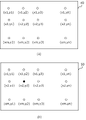
- FIG. 6 is an example diagram showing a user's stay position in the area.
- FIG. 6A is a seat layout diagram 42 showing a certain coordinate position of a seat in the area
- FIG. 6B shows a table 60 in which the user and the stay position (seat) are associated with each other.
- the coordinate position indicating the seat position of the person with the user ID 50a is (x1, y1)
- the coordinate position indicating the seat position of the person with the user ID 50b is (x1, y2)
- the user ID is 50c.
- the coordinate position indicating the seat position of the person is (x1, y3)
- the coordinate position indicating the seat position of the person with the user ID of 50z is (xm, ym).
- the data associated with the user ID which is the information associated with each user, and the coordinate position information indicating the seat position of the user is stored in the storage unit 270.
- FIG. 5 shows that each user has a remote terminal 32.
- Each remote terminal 32 transmits including a user ID that identifies the user in use. Further, here, it is sufficient to specify the setting information such as the set temperature at the position where the user is located without selecting the position to be set in the area.
- the receiving unit 262 receives a signal including setting information and user ID information from each remote terminal 32, and outputs the signal to the setting information acquisition unit 232.
- the setting information acquisition unit 232 is based on the data obtained by associating the user ID information acquired together with the setting information acquired from the reception unit 262 with the coordinate position information indicating the seat position of the user ID stored in the storage unit 270.
- the coordinate position associated with the user ID of the user who transmitted the setting information acquired from the receiving unit 262 is set as the position where the setting information is to be set, and the position to be set and the setting information are supplied to the reference heat distribution generation unit 240.
- the remote terminal 32 even if the remote terminal 32 does not have a user interface for designating the setting position after specifying the setting position, it only transmits the setting information such as the temperature and humidity of the seated position. The same effect can be achieved with a simple application.
- the receiving unit 262 may transmit the heat distribution information and the generated reference heat distribution information to the respective remote terminals as the transmitting / receiving unit.
- the storage unit 270 stores the data associated with the user ID and the stay position (seat), and further stores the transmission history of what kind of settings each user has transmitted in the past. .. Then, the user can acquire the information toward the room provided with the air conditioner 23, and generate and reflect the reference heat distribution based on the transmission history in advance before the user enters the area. can. For example, the setting set in the past by the user who is trying to enter the area is compared with the current heat distribution information at the user's seat position, and if the difference is larger than a predetermined threshold value, the user enters the room.
- control is performed by reflecting it in the reference heat distribution before transmitting the setting, and if it is below a predetermined threshold value, it is not reflected in the reference heat distribution from the time the user enters the room until the setting is transmitted.
- the storage unit 270 has the same effect even if it is a setting history instead of a transmission history.
- FIG. 7 shows an example of data stored in the storage unit 270 according to the present embodiment as Table 61.
- information indicating the seat position of the user, the premises entry / exit information of the user, and the transmission history of what kind of setting the user last transmitted is stored in association with the user ID.
- the entry / exit information on the premises for example, if there is an entry / exit management system that opens and closes by user authentication at the entrance / exit of the building or floor where the air conditioner 23 is installed, that information is used. Alternatively, if there is a premises entry / exit management system that opens and closes by user authentication at the entrance / exit of the building premises where the room provided with the air conditioner 23 is provided, that information is utilized.
- FIG. 8 is a block diagram schematically showing the configuration of the air conditioning system according to the present embodiment.
- an air conditioning system including a plurality of air conditioners 23 and a centralized control device 70 communicably connected to the plurality of air conditioners 23 is shown.
- control unit is independent as the centralized control device 70, and the respective air conditioners are harmonized. This is realized by transmitting control information to each machine 23.
- the centralized control device 70 shown in FIG. 8 corresponds to the air conditioner 20 shown in FIG. In FIG. 8, three air conditioners 23a, an air conditioner 23b, and an air conditioner 23c are communicably connected to each other. This connection is not limited to a wired connection, and may be in a state where communication is possible wirelessly.
- the control information generation unit 710 reduces the difference between the heat distribution information and the reference heat distribution information from the heat distribution information from the heat distribution generation unit 220 and the reference heat distribution information from the reference heat distribution generation unit 240. It generates control information to be controlled for each air conditioner 23. Here, it is assumed that the control information generation unit 710 grasps the position information provided for each air conditioner 23.
- the communication unit 720 transmits the control information generated by the control information generation unit 710 to each air conditioner 23.
- control information may be transmitted for each air conditioner 23.
- a device ID may be assigned to each air conditioner 23 in advance, and control information may be transmitted together with the device ID.
- Each air conditioner 23 receives a transmission signal including control information from the centralized control device 70, and if the transmitted control information includes control information related to the own unit, the air conditioner 23 responds to the control information. Adjust the temperature and humidity, wind direction, and air volume of the air to be transmitted.
- the centralized control device 70 communicably connected to the air conditioners 23 provided with them can be used for heat distribution information and reference in the region.
- the entire region where the plurality of air conditioners 23 are provided is used. Even if there is, it can be effective.
- the communication unit 720 may be configured to receive information from the temperature sensor 10 communicably connected to each air conditioner 23 and send it to the temperature information acquisition unit 210. With such a method, the temperature information in the region can be acquired without the temperature sensor 10 to which the centralized control device 70 is directly connected so as to be able to communicate directly.
- the communication unit 720 may be configured to receive information from the remote terminal 30 communicably connected to each air conditioner 23 and send it to the setting information acquisition unit 230.
- the centralized control device 70 can acquire the setting information from the user in the area even if there is no remote terminal 30 directly connected to the centralized control device 70 so as to be able to communicate directly.
- the centralized control device 70 does not need to be provided in the corresponding area, and is not limited to the edge server in the premises but the Internet.
- the function can be executed by a cloud server or the like outside the premises that is communicably connected to each air conditioner 23 via the air conditioner 23.
- the centralized control device 70 is shown corresponding to the air conditioner 20 shown in FIG. 1, but is configured to correspond to the air conditioner 21 of FIG. 4 and the air conditioner 22 of FIG.
- the effects of each embodiment are achieved.
- the centralized control device 70 can execute its function on a computer server or the like.
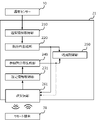
- FIG. 9 is a diagram showing the centralized control device 70 using a processor.
- the processor 711 is connected to a memory 712, a key input / output interface (hereinafter, I / F) 713, a data input / output I / F715, and a display output I / F714.
- I / F key input / output interface
- the processor 711 is hardware that operates when a program for executing the process of the present disclosure is executed using the memory 712.
- the key input / output I / F 713 is used when connected to a touch key device such as a keyboard or a remote terminal 30 to set a threshold value from the user.
- the data input / output I / F 715 is used when connected to the temperature sensor 10 to acquire temperature information. It is also used when acquiring information on entering and exiting the premises.
- the data input / output I / F 715 is connected to an external storage device and records user position information, previous setting information for each user, installation position information of the air conditioner 23, etc. by accessing the external storage device (not shown). It doesn't matter.
- the display output I / F 714 is used for displaying heat distribution information and the like.
Landscapes
- Engineering & Computer Science (AREA)
- Signal Processing (AREA)
- Physics & Mathematics (AREA)
- Chemical & Material Sciences (AREA)
- Combustion & Propulsion (AREA)
- Mechanical Engineering (AREA)
- General Engineering & Computer Science (AREA)
- Fuzzy Systems (AREA)
- Mathematical Physics (AREA)
- Fluid Mechanics (AREA)
- Air Conditioning Control Device (AREA)
Priority Applications (5)
| Application Number | Priority Date | Filing Date | Title |
|---|---|---|---|
| PCT/JP2020/036109 WO2022064615A1 (ja) | 2020-09-24 | 2020-09-24 | 空気調和機および空気調和システム |
| EP20955209.0A EP4220029A4 (en) | 2020-09-24 | 2020-09-24 | AIR CONDITIONER AND AIR CONDITIONING SYSTEM |
| EP24197634.9A EP4450892A3 (en) | 2020-09-24 | 2020-09-24 | Air conditioner |
| US18/024,279 US20230324068A1 (en) | 2020-09-24 | 2020-09-24 | Air conditioner and air conditioning system |
| JP2022551507A JP7523561B2 (ja) | 2020-09-24 | 2020-09-24 | 空気調和機、空気調和システム、および制御方法 |
Applications Claiming Priority (1)
| Application Number | Priority Date | Filing Date | Title |
|---|---|---|---|
| PCT/JP2020/036109 WO2022064615A1 (ja) | 2020-09-24 | 2020-09-24 | 空気調和機および空気調和システム |
Publications (1)
| Publication Number | Publication Date |
|---|---|
| WO2022064615A1 true WO2022064615A1 (ja) | 2022-03-31 |
Family
ID=80844781
Family Applications (1)
| Application Number | Title | Priority Date | Filing Date |
|---|---|---|---|
| PCT/JP2020/036109 Ceased WO2022064615A1 (ja) | 2020-09-24 | 2020-09-24 | 空気調和機および空気調和システム |
Country Status (4)
| Country | Link |
|---|---|
| US (1) | US20230324068A1 (https=) |
| EP (2) | EP4450892A3 (https=) |
| JP (1) | JP7523561B2 (https=) |
| WO (1) | WO2022064615A1 (https=) |
Citations (4)
| Publication number | Priority date | Publication date | Assignee | Title |
|---|---|---|---|---|
| JP2011094965A (ja) | 2007-06-13 | 2011-05-12 | Mitsubishi Electric Corp | 空気調和機およびこの空気調和機を備えた空気調和システム |
| WO2019026098A1 (ja) * | 2017-07-31 | 2019-02-07 | 三菱電機株式会社 | 空気調和システム及びゾーン空調制御方法 |
| WO2019224916A1 (ja) * | 2018-05-22 | 2019-11-28 | 三菱電機株式会社 | 空気調和装置およびこれを有する倉庫 |
| JP2020148385A (ja) * | 2019-03-13 | 2020-09-17 | ダイキン工業株式会社 | 空調制御システム、及び、空調制御方法 |
Family Cites Families (7)
| Publication number | Priority date | Publication date | Assignee | Title |
|---|---|---|---|---|
| KR100565486B1 (ko) * | 2003-06-11 | 2006-03-30 | 엘지전자 주식회사 | 에어컨의 중앙제어 시스템 및 그 동작방법 |
| JP5111445B2 (ja) * | 2008-09-10 | 2013-01-09 | 三菱電機株式会社 | 空気調和機 |
| JP5083301B2 (ja) * | 2009-12-01 | 2012-11-28 | 株式会社デンソーウェーブ | セントラル空調システム |
| JP2016188746A (ja) | 2015-03-30 | 2016-11-04 | パナソニックIpマネジメント株式会社 | 制御システム、制御方法及び制御プログラム |
| US9644857B1 (en) * | 2015-12-01 | 2017-05-09 | Nasser Ashgriz | Virtual thermostat for a zonal temperature control |
| JP2019027603A (ja) * | 2017-07-25 | 2019-02-21 | 三菱重工サーマルシステムズ株式会社 | 空調制御装置、空調システム、空調制御方法、及びプログラム |
| US11249449B2 (en) * | 2017-11-06 | 2022-02-15 | Mitsubishi Electric Corporation | Operation terminal, non-transitory computer-readable medium and air-conditioning system |
-
2020
- 2020-09-24 EP EP24197634.9A patent/EP4450892A3/en not_active Withdrawn
- 2020-09-24 US US18/024,279 patent/US20230324068A1/en active Pending
- 2020-09-24 WO PCT/JP2020/036109 patent/WO2022064615A1/ja not_active Ceased
- 2020-09-24 JP JP2022551507A patent/JP7523561B2/ja active Active
- 2020-09-24 EP EP20955209.0A patent/EP4220029A4/en not_active Withdrawn
Patent Citations (4)
| Publication number | Priority date | Publication date | Assignee | Title |
|---|---|---|---|---|
| JP2011094965A (ja) | 2007-06-13 | 2011-05-12 | Mitsubishi Electric Corp | 空気調和機およびこの空気調和機を備えた空気調和システム |
| WO2019026098A1 (ja) * | 2017-07-31 | 2019-02-07 | 三菱電機株式会社 | 空気調和システム及びゾーン空調制御方法 |
| WO2019224916A1 (ja) * | 2018-05-22 | 2019-11-28 | 三菱電機株式会社 | 空気調和装置およびこれを有する倉庫 |
| JP2020148385A (ja) * | 2019-03-13 | 2020-09-17 | ダイキン工業株式会社 | 空調制御システム、及び、空調制御方法 |
Non-Patent Citations (1)
| Title |
|---|
| See also references of EP4220029A4 |
Also Published As
| Publication number | Publication date |
|---|---|
| JP7523561B2 (ja) | 2024-07-26 |
| JPWO2022064615A1 (https=) | 2022-03-31 |
| EP4450892A3 (en) | 2025-01-22 |
| EP4450892A2 (en) | 2024-10-23 |
| EP4220029A1 (en) | 2023-08-02 |
| US20230324068A1 (en) | 2023-10-12 |
| EP4220029A4 (en) | 2024-04-03 |
Similar Documents
| Publication | Publication Date | Title |
|---|---|---|
| US10951750B2 (en) | Networked thermostat control for ductless HVAC | |
| US10359747B2 (en) | Controlling device, controlling system and controlling method for indoor apparatus | |
| KR102121785B1 (ko) | 인공지능을 이용하여 지시된 위치로 풍향을 제어하는 에어컨 및 이를 제어하는 방법 | |
| CN105446162A (zh) | 一种智能家居系统以及机器人的智能家居控制方法 | |
| JP6282926B2 (ja) | 制御方法及び通信装置 | |
| US11913663B2 (en) | Air-conditioning control device and air-conditioning control system | |
| JP2015052435A (ja) | 空気調和機 | |
| WO2016157675A1 (ja) | 制御システム、制御方法及び制御プログラム | |
| JP6790249B2 (ja) | 空調装置、空調システム、空調方法及びプログラム | |
| JP2012172910A (ja) | 室内環境調整用機器の操作システム | |
| KR20120039359A (ko) | 스마트폰과 센서를 이용한 인공지능 디지털기기 제어시스템 | |
| US11249449B2 (en) | Operation terminal, non-transitory computer-readable medium and air-conditioning system | |
| EP2696146B1 (en) | Air conditioning system | |
| KR102206461B1 (ko) | 공기조화기 시스템 및 그 동작방법 | |
| KR20170090668A (ko) | 공기조화기 및 그 제어방법 | |
| JP2022157918A (ja) | 空調システム | |
| WO2022064615A1 (ja) | 空気調和機および空気調和システム | |
| CN112696785A (zh) | 空调器控制方法、控制系统和空调器 | |
| WO2018066035A1 (ja) | コントローラ、空気調和システムおよび空気調和機の制御方法 | |
| WO2018211592A1 (ja) | 空気調和システム | |
| KR20180091997A (ko) | 멀티미디어 채팅을 통한 IoT 기반의 전원 릴레이 제어시스템 및 그 방법 | |
| CN104791959B (zh) | 空调器的控制方法及系统、移动终端和空调器 | |
| JPH02133740A (ja) | 空気調和機の制御装置 | |
| JP2022157917A (ja) | 空調システム | |
| WO2021070219A1 (ja) | 空気調和システム |
Legal Events
| Date | Code | Title | Description |
|---|---|---|---|
| 121 | Ep: the epo has been informed by wipo that ep was designated in this application |
Ref document number: 20955209 Country of ref document: EP Kind code of ref document: A1 |
|
| ENP | Entry into the national phase |
Ref document number: 2022551507 Country of ref document: JP Kind code of ref document: A |
|
| NENP | Non-entry into the national phase |
Ref country code: DE |
|
| ENP | Entry into the national phase |
Ref document number: 2020955209 Country of ref document: EP Effective date: 20230424 |