WO2022064603A1 - レンズ装置、レンズ装置が組み込まれたシステム、レンズ装置が組み込まれた検査装置、並びに操作用プログラム - Google Patents
レンズ装置、レンズ装置が組み込まれたシステム、レンズ装置が組み込まれた検査装置、並びに操作用プログラム Download PDFInfo
- Publication number
- WO2022064603A1 WO2022064603A1 PCT/JP2020/036067 JP2020036067W WO2022064603A1 WO 2022064603 A1 WO2022064603 A1 WO 2022064603A1 JP 2020036067 W JP2020036067 W JP 2020036067W WO 2022064603 A1 WO2022064603 A1 WO 2022064603A1
- Authority
- WO
- WIPO (PCT)
- Prior art keywords
- lens
- control unit
- operation terminal
- communication interface
- unit
- Prior art date
- Legal status (The legal status is an assumption and is not a legal conclusion. Google has not performed a legal analysis and makes no representation as to the accuracy of the status listed.)
- Ceased
Links
Images


Classifications
-
- H—ELECTRICITY
- H04—ELECTRIC COMMUNICATION TECHNIQUE
- H04N—PICTORIAL COMMUNICATION, e.g. TELEVISION
- H04N23/00—Cameras or camera modules comprising electronic image sensors; Control thereof
- H04N23/60—Control of cameras or camera modules
- H04N23/66—Remote control of cameras or camera parts, e.g. by remote control devices
- H04N23/661—Transmitting camera control signals through networks, e.g. control via the Internet
-
- G—PHYSICS
- G02—OPTICS
- G02B—OPTICAL ELEMENTS, SYSTEMS OR APPARATUS
- G02B7/00—Mountings, adjusting means, or light-tight connections, for optical elements
- G02B7/02—Mountings, adjusting means, or light-tight connections, for optical elements for lenses
- G02B7/04—Mountings, adjusting means, or light-tight connections, for optical elements for lenses with mechanism for focusing or varying magnification
- G02B7/09—Mountings, adjusting means, or light-tight connections, for optical elements for lenses with mechanism for focusing or varying magnification adapted for automatic focusing or varying magnification
-
- G—PHYSICS
- G02—OPTICS
- G02B—OPTICAL ELEMENTS, SYSTEMS OR APPARATUS
- G02B7/00—Mountings, adjusting means, or light-tight connections, for optical elements
- G02B7/02—Mountings, adjusting means, or light-tight connections, for optical elements for lenses
- G02B7/04—Mountings, adjusting means, or light-tight connections, for optical elements for lenses with mechanism for focusing or varying magnification
- G02B7/10—Mountings, adjusting means, or light-tight connections, for optical elements for lenses with mechanism for focusing or varying magnification by relative axial movement of several lenses, e.g. of varifocal objective lens
- G02B7/102—Mountings, adjusting means, or light-tight connections, for optical elements for lenses with mechanism for focusing or varying magnification by relative axial movement of several lenses, e.g. of varifocal objective lens controlled by a microcomputer
-
- G—PHYSICS
- G03—PHOTOGRAPHY; CINEMATOGRAPHY; ANALOGOUS TECHNIQUES USING WAVES OTHER THAN OPTICAL WAVES; ELECTROGRAPHY; HOLOGRAPHY
- G03B—APPARATUS OR ARRANGEMENTS FOR TAKING PHOTOGRAPHS OR FOR PROJECTING OR VIEWING THEM; APPARATUS OR ARRANGEMENTS EMPLOYING ANALOGOUS TECHNIQUES USING WAVES OTHER THAN OPTICAL WAVES; ACCESSORIES THEREFOR
- G03B13/00—Viewfinders; Focusing aids for cameras; Means for focusing for cameras; Autofocus systems for cameras
- G03B13/32—Means for focusing
- G03B13/34—Power focusing
-
- G—PHYSICS
- G03—PHOTOGRAPHY; CINEMATOGRAPHY; ANALOGOUS TECHNIQUES USING WAVES OTHER THAN OPTICAL WAVES; ELECTROGRAPHY; HOLOGRAPHY
- G03B—APPARATUS OR ARRANGEMENTS FOR TAKING PHOTOGRAPHS OR FOR PROJECTING OR VIEWING THEM; APPARATUS OR ARRANGEMENTS EMPLOYING ANALOGOUS TECHNIQUES USING WAVES OTHER THAN OPTICAL WAVES; ACCESSORIES THEREFOR
- G03B17/00—Details of cameras or camera bodies; Accessories therefor
- G03B17/02—Bodies
- G03B17/12—Bodies with means for supporting objectives, supplementary lenses, filters, masks, or turrets
- G03B17/14—Bodies with means for supporting objectives, supplementary lenses, filters, masks, or turrets interchangeably
-
- G—PHYSICS
- G03—PHOTOGRAPHY; CINEMATOGRAPHY; ANALOGOUS TECHNIQUES USING WAVES OTHER THAN OPTICAL WAVES; ELECTROGRAPHY; HOLOGRAPHY
- G03B—APPARATUS OR ARRANGEMENTS FOR TAKING PHOTOGRAPHS OR FOR PROJECTING OR VIEWING THEM; APPARATUS OR ARRANGEMENTS EMPLOYING ANALOGOUS TECHNIQUES USING WAVES OTHER THAN OPTICAL WAVES; ACCESSORIES THEREFOR
- G03B3/00—Focusing arrangements of general interest for cameras, projectors or printers
- G03B3/10—Power-operated focusing
-
- G—PHYSICS
- G03—PHOTOGRAPHY; CINEMATOGRAPHY; ANALOGOUS TECHNIQUES USING WAVES OTHER THAN OPTICAL WAVES; ELECTROGRAPHY; HOLOGRAPHY
- G03B—APPARATUS OR ARRANGEMENTS FOR TAKING PHOTOGRAPHS OR FOR PROJECTING OR VIEWING THEM; APPARATUS OR ARRANGEMENTS EMPLOYING ANALOGOUS TECHNIQUES USING WAVES OTHER THAN OPTICAL WAVES; ACCESSORIES THEREFOR
- G03B5/00—Adjustment of optical system relative to image or object surface other than for focusing
-
- G—PHYSICS
- G03—PHOTOGRAPHY; CINEMATOGRAPHY; ANALOGOUS TECHNIQUES USING WAVES OTHER THAN OPTICAL WAVES; ELECTROGRAPHY; HOLOGRAPHY
- G03B—APPARATUS OR ARRANGEMENTS FOR TAKING PHOTOGRAPHS OR FOR PROJECTING OR VIEWING THEM; APPARATUS OR ARRANGEMENTS EMPLOYING ANALOGOUS TECHNIQUES USING WAVES OTHER THAN OPTICAL WAVES; ACCESSORIES THEREFOR
- G03B7/00—Control of exposure by setting shutters, diaphragms or filters, separately or conjointly
- G03B7/26—Power supplies; Circuitry or arrangement to switch on the power source; Circuitry to check the power source voltage
-
- H—ELECTRICITY
- H04—ELECTRIC COMMUNICATION TECHNIQUE
- H04N—PICTORIAL COMMUNICATION, e.g. TELEVISION
- H04N23/00—Cameras or camera modules comprising electronic image sensors; Control thereof
- H04N23/50—Constructional details
- H04N23/54—Mounting of pick-up tubes, electronic image sensors, deviation or focusing coils
-
- H—ELECTRICITY
- H04—ELECTRIC COMMUNICATION TECHNIQUE
- H04N—PICTORIAL COMMUNICATION, e.g. TELEVISION
- H04N23/00—Cameras or camera modules comprising electronic image sensors; Control thereof
- H04N23/50—Constructional details
- H04N23/55—Optical parts specially adapted for electronic image sensors; Mounting thereof
-
- H—ELECTRICITY
- H04—ELECTRIC COMMUNICATION TECHNIQUE
- H04N—PICTORIAL COMMUNICATION, e.g. TELEVISION
- H04N23/00—Cameras or camera modules comprising electronic image sensors; Control thereof
- H04N23/57—Mechanical or electrical details of cameras or camera modules specially adapted for being embedded in other devices
-
- H—ELECTRICITY
- H04—ELECTRIC COMMUNICATION TECHNIQUE
- H04N—PICTORIAL COMMUNICATION, e.g. TELEVISION
- H04N23/00—Cameras or camera modules comprising electronic image sensors; Control thereof
- H04N23/60—Control of cameras or camera modules
- H04N23/665—Control of cameras or camera modules involving internal camera communication with the image sensor, e.g. synchronising or multiplexing SSIS control signals
-
- H—ELECTRICITY
- H04—ELECTRIC COMMUNICATION TECHNIQUE
- H04N—PICTORIAL COMMUNICATION, e.g. TELEVISION
- H04N23/00—Cameras or camera modules comprising electronic image sensors; Control thereof
- H04N23/60—Control of cameras or camera modules
- H04N23/69—Control of means for changing angle of the field of view, e.g. optical zoom objectives or electronic zooming
-
- G—PHYSICS
- G03—PHOTOGRAPHY; CINEMATOGRAPHY; ANALOGOUS TECHNIQUES USING WAVES OTHER THAN OPTICAL WAVES; ELECTROGRAPHY; HOLOGRAPHY
- G03B—APPARATUS OR ARRANGEMENTS FOR TAKING PHOTOGRAPHS OR FOR PROJECTING OR VIEWING THEM; APPARATUS OR ARRANGEMENTS EMPLOYING ANALOGOUS TECHNIQUES USING WAVES OTHER THAN OPTICAL WAVES; ACCESSORIES THEREFOR
- G03B2205/00—Adjustment of optical system relative to image or object surface other than for focusing
- G03B2205/0046—Movement of one or more optical elements for zooming
-
- G—PHYSICS
- G03—PHOTOGRAPHY; CINEMATOGRAPHY; ANALOGOUS TECHNIQUES USING WAVES OTHER THAN OPTICAL WAVES; ELECTROGRAPHY; HOLOGRAPHY
- G03B—APPARATUS OR ARRANGEMENTS FOR TAKING PHOTOGRAPHS OR FOR PROJECTING OR VIEWING THEM; APPARATUS OR ARRANGEMENTS EMPLOYING ANALOGOUS TECHNIQUES USING WAVES OTHER THAN OPTICAL WAVES; ACCESSORIES THEREFOR
- G03B2205/00—Adjustment of optical system relative to image or object surface other than for focusing
- G03B2205/0053—Driving means for the movement of one or more optical element
-
- G—PHYSICS
- G03—PHOTOGRAPHY; CINEMATOGRAPHY; ANALOGOUS TECHNIQUES USING WAVES OTHER THAN OPTICAL WAVES; ELECTROGRAPHY; HOLOGRAPHY
- G03B—APPARATUS OR ARRANGEMENTS FOR TAKING PHOTOGRAPHS OR FOR PROJECTING OR VIEWING THEM; APPARATUS OR ARRANGEMENTS EMPLOYING ANALOGOUS TECHNIQUES USING WAVES OTHER THAN OPTICAL WAVES; ACCESSORIES THEREFOR
- G03B2206/00—Systems for exchange of information between different pieces of apparatus, e.g. for exchanging trimming information, for photo finishing
Definitions
- the present invention can be connected to an external operation terminal via a network, and has a lens device used for industrial inspection and the like, a system incorporating a lens device, an inspection device incorporating a lens device, and an operation device.
- the present invention relates to a lens device capable of outputting a response signal of a lens operation of a lens body in real time, a system incorporating the lens device, an inspection device incorporating the lens device, and an operation program.
- IP cameras network cameras
- CCTV Computer-circuit Television
- FA Computer Automation
- a compatible lens mount such as a C mount or CS mount
- a single focus lens or a variable focus lens zoom lens, varifocal lens, etc.
- Those configured to be wearable are known.
- an optical image is formed through the lens mechanism by driving and controlling the focus, zoom, and iris lens mechanism, and the optical image is imaged as electrical signal image data by an image pickup element.
- the image data is processed by photoelectric conversion, and the visible image is displayed on the operation screen.
- focus adjustment In single focus lenses and varifocal lenses, focus adjustment, zoom adjustment, and iris adjustment are possible by driving the focus and zoom as well as the iris lens mechanism, and a DC motor or stepping motor is used to make these adjustments. And electrified products are widely known.
- Patent Document 1 discloses a camera device in which a DC motor or a stepping motor is applied to drive control of a lens mechanism and the lens mechanism is remotely controlled by an operation terminal.
- the CCTV lens of Patent Document 1 incorporates a control unit in a varifocal lens, and power is supplied to the control unit and the motor by an external control device.
- the board of the control unit is composed of a flexible circuit, and it is possible to wire directly from the flexible circuit to each motor for driving the lens, which can reduce the number of wires and simplify the motor wiring. It was done.
- a microcomputer is provided on the flexible circuit, and the microcomputer is connected to an external control device by a serial communication line, and controls each motor of the CCTV lens based on a command from the control device from the camera side. Adjust the zoom and focus.
- the CCTV lens of Patent Document 1 is intended to simplify the wiring to each motor for driving the lens and the lens control.
- connection form between the lens and the operation terminal is a one-to-one configuration by a cable
- the configuration and control of the communication line are required. It may be complicated.
- the lens device according to the present invention was developed for the purpose of enabling the present inventors to output the operating state of the lens in real time while utilizing a general-purpose communication interface capable of connecting a large number of camera devices. It was done.
- the lens device of the present invention has a signal line that outputs a trigger signal having real-time characteristics separately from the general-purpose communication interface and the general-purpose communication interface, and outputs the operation information of the lens that requires real-time characteristics as a separate signal. By doing so, it is possible to reduce the load on the host side, which is the terminal device, until the lens operation is completed, starting from the lens drive control, and the image is captured and processed immediately after the lens operation is completed. It is an object of the present invention to provide a lens device suitable for inspection by image processing, a system incorporating a lens device, an inspection device incorporating a lens device, and an operation program.
- the lens device is a lens device for capturing an optical image with a camera body, and has a lens mechanism built in the lens body for forming the optical image and the above-mentioned. It has a drive control unit built in the lens body that drives and controls the lens mechanism, a control unit that outputs a drive control signal to the drive control unit, and a first communication interface capable of communicating with the control unit. It is characterized by having a first connection unit that can be connected to the network and a second connection unit that includes a second communication interface that can output a signal from the control unit.
- the lens mechanism in the lens device starts operation by a movement operation command input to the control unit from the first communication interface of the first connection unit, and the lens mechanism operates in the control unit.
- the operation completion signal notifying that the operation is completed is output from the second communication interface of the second connection unit.
- the lens device according to the present invention is characterized in that the lens body is driven and controlled independently of the camera body based on a movement operation command from the control unit.
- the lens device connects an operation terminal having a computer on the network to which the lens device is connected, and the lens device from the operation terminal on the network network via the first communication interface. After receiving the movement operation command of the lens mechanism output to the control unit of the lens device, the control unit of the lens device outputs an operation completion signal of the lens mechanism to the operation terminal via the second communication interface. It is characterized by that.
- the first connection portion of the lens device according to the present invention is further characterized by having a power supply interface for supplying power to the lens body.
- the system in which the lens device according to the present invention is incorporated includes a camera body for capturing an optical image, a lens device having a lens body coupled to the camera body via a mount portion, and the above-mentioned via a network. It has an operation terminal for controlling the lens device, a lens mechanism built in the lens body for forming an optical image, and a drive control unit built in the lens body for driving and controlling the lens mechanism.
- the operation terminal is characterized by having a second connection unit provided with a second communication interface capable of outputting a signal.
- the system in which the lens device according to the present invention is incorporated controls the lens body independently of the camera body based on a movement operation command from the operation terminal, and controls the second connection portion of the lens device. It is characterized in that an operation completion signal is output to the operation terminal by the communication interface of 2.
- the inspection device incorporating the lens device according to the present invention includes a camera body for capturing an optical image, a lens device having a lens body coupled to the camera body via a mount portion, and a network. It has an operation terminal for controlling the lens device, a lens mechanism built in the lens body for forming an optical image, and a drive control unit built in the lens body to drive and control the lens mechanism.
- a control unit that outputs a drive control signal to the drive control unit, a first connection unit that has a first communication interface capable of communicating with the control unit and can be connected to the network, and the control unit. It is characterized by having a second connection unit provided with a second communication interface capable of outputting a signal from the unit to the operation terminal, and inspecting an object to be inspected.
- the operation program for controlling the lens device includes a lens mechanism built in the lens body for forming an optical image, and a drive control unit built in the lens body for driving and controlling the lens mechanism.
- a control unit that outputs a drive control signal to the drive control unit, a first connection unit that has a first communication interface capable of communicating with the control unit and can be connected to the network, and the control unit.
- a lens device having a second connection unit provided with a second communication interface capable of outputting a signal from the unit to the operation terminal, from the operation terminal input to the first communication interface of the first connection unit.
- It has a function of receiving the command of the above and a function of executing a command based on the command received from the operation terminal, and when a command to move the position of the lens of the lens mechanism is received from the operation terminal. , A function of outputting a drive control signal to the drive control unit to move the position of the lens, a function of checking whether the lens of the lens mechanism has completed the moving operation, and a function of checking whether the lens of the lens mechanism has completed the moving operation. After that, the function of outputting a trigger signal, which is a movement completion signal of the lens mechanism, to the operation terminal is executed from the second communication interface.
- the operation program for controlling the lens device has a function of storing the position of the lens of the lens mechanism as address information and reading the address information of the lens mechanism stored in advance to read the address information of the network.
- the function of outputting a command to move to the moving position of the address information read out to the lens device by the first communication interface and the function of receiving the movement completion signal of the lens mechanism from the second communication interface are executed. It is characterized by that.
- the general-purpose communication interface and the general-purpose communication interface have a signal line for outputting a trigger signal having real-time property independent of the general-purpose interface, and information requiring real-time property from the lens device.
- a trigger signal having real-time property independent of the general-purpose interface, and information requiring real-time property from the lens device.
- the general-purpose communication interface and the general-purpose communication interface are provided with a signal line for outputting a trigger signal having real-time property independent of the general-purpose interface, so that the lens requires real-time property.
- a lens mechanism built in the lens body for forming an optical image a drive control unit built in the lens body to drive and control the lens mechanism, and a drive control signal in the drive control unit. Since it has a central processing unit (control unit) that outputs the lens and a network that forms a communication interface to the central processing unit (control unit), the lens and the operation terminal are connected by a network network, and the lens and the operation terminal are connected.
- the connection form between terminals can be expanded to n to 1 or n to n connection form.
- the lens device can output the lens operating state in real time while making use of a general-purpose communication interface capable of connecting a large number of camera devices. There is no delay in processing while waiting for confirmation of the completion of lens operation. As a result, other processing can be performed while the operating terminal is waiting for confirmation of the completion of the operation of the lens, so that the processing efficiency of the operating terminal is improved.
- the lens device has a signal line for outputting a trigger signal having real-time property in addition to the general-purpose communication interface, and the lens device and the terminal device are directly connected by the signal line. Therefore, the configuration between the devices can be simplified.
- the signal line of the second connection portion of the lens device is only the output from the lens device, it can be used only when real-time performance is required.
- connection form between multiple lens devices and the operation terminal can be expanded to an n-to-1 form, in the case of an industrial camera that requires real-time response, synchronization is performed with multiple lens devices. Or, even when an arbitrary number of lens devices are selected from a plurality of lens devices and driven and controlled, it is possible to immediately respond.
- the present invention can be operated from the operation terminal independently of the camera body, it is possible to control a plurality of lens devices and to observe the information of each lens device in real time.
- multiple lens devices are aggregated in a network network and connected to one operation terminal, or multiple lenses are connected. It is possible to adopt a configuration in which a plurality of operation terminals are connected on a network having a lens device, and the application range of the lens device can be expanded.
- the operation terminal that controls the lens device stores the lens position of the lens mechanism set in advance, the lens position information stored in the inspection by image processing or the like is read out to move the lens to a predetermined position at high speed. Can be controlled with.
- the operation terminal that controls the lens device can receive the signal of the completion of the operation of the lens of the lens mechanism in real time, high-speed processing is possible in the inspection device that processes and inspects the image from the camera body.
- FIG. 1 It is a block diagram which shows the structure of the lens apparatus and the operation terminal which concerns on embodiment of this invention.
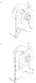
- the appearance of the varifocal lens as the lens body in the embodiment of the present invention is shown, (a) is a perspective view showing the lens body according to the embodiment of the present invention, and (b) is the lens body according to the embodiment of the present invention.
- the side view shown, (c) is the side view which shows the state which the lens body which concerns on embodiment of this invention shown in (a) is rotated 90 degrees around an optical axis.
- (A) is a view in which the USB connector from the first connection portion and the connector from the second connection portion of the lens body are pulled out in the embodiment of the present invention, and is a perspective view of the lens body as viewed from the rear, (b).
- FIG. 1 It is a block diagram which shows the example of the network network of the n-to-n connection form of the lens body and the operation terminal which concerns on embodiment of this invention, and the structure which connected the 2nd connection part of a lens apparatus, and the operation terminal via an encoder. Is shown.
- (A) is a timing chart diagram in the case where the operation terminal (host) side of the lens device confirms the operating state (status) of the drive motor using the first communication interface
- (b) is the present invention. It is a timing chart diagram in the case where the operation terminal (host) side of the lens apparatus according to the above is used to confirm the operation state (status) of the drive motor by using the second communication interface.
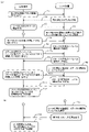
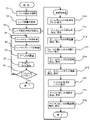
- FIG. 1 shows the display example of the operation screen of the operation terminal in embodiment of this invention. It is a flowchart explaining a series of operation of the lens mechanism in embodiment of this invention. It is a flowchart explaining the operation of the operation terminal and the lens apparatus when the lens mechanism in embodiment of this invention is used for an inspection apparatus.
- the lens device according to the present invention completes the lens operation starting from the lens drive operation by outputting the lens operation information requiring real-time performance as a separate signal without going through a general-purpose communication interface. It is possible to reduce the load on the host side, which is the operating terminal, until the response is completed, and it is also possible to take an image with a camera device immediately after the lens operation is completed and perform an inspection by image processing at high speed. be.
- FIG. 1 is a block diagram showing a configuration of a lens device and an operation terminal according to an embodiment of the present invention.
- the lens device 1 according to the embodiment of the present invention is a lens device 1 for capturing an optical image by a camera device 19, and is built in the lens body 2 to form an optical image.
- the zoom adjustment lens mechanism 3, the focus adjustment lens mechanism 4, and the iris adjustment unit mechanism 5 (the zoom adjustment lens mechanism 3, the focus adjustment lens mechanism 4, and the iris adjustment unit mechanism 5 are referred to as a lens mechanism).
- a drive control unit for zoom 6 as a drive control unit for driving and controlling the lens mechanism, a drive control unit 7 for focus, a drive control unit 8 for optics, and a drive control signal are output to the drive control unit, which is built in the lens body 2.
- the power supply interface 13a for supplying power to the lens body 2 the first connection unit 13 forming the first communication interface 13b capable of communicating with the control unit 9, and the control unit 9. It has a second connection portion including a second communication interface 16a capable of outputting the signal of.
- the zoom adjustment lens mechanism 3 for zoom adjustment is composed of a zoom lead screw 3a for moving the lens to change the focal length and a zoom drive motor 3c.
- the focus lens mechanism 4 for moving the lens to adjust the focus is composed of a focus lead screw 4a and a focus drive motor 4c.
- the iris adjusting unit mechanism 5 for adjusting the iris is composed of an iris unit 5a for varying the aperture F value and a drive motor 5c for the iris.
- the zoom drive control unit 6 drives and controls the zoom drive motor 3c based on the command of the control unit 9 that controls the zoom drive motor 3c of the zoom adjustment lens mechanism 3. As a result, the zoom adjustment of the zoom adjustment lens mechanism 3 is performed.
- the focus drive control unit 7 drives and controls the focus drive motor 4c based on the command of the control unit 9 that controls the focus drive motor 4c of the focus adjustment lens mechanism 4. As a result, the focus of the focus drive control unit 7 is adjusted.
- the iris drive control unit 8 drives and controls the iris drive motor 5c based on the command of the control unit 9 that controls the iris drive motor 5c of the iris adjustment unit mechanism 5. As a result, the iris of the iris adjusting unit mechanism 5 is adjusted.
- the control unit 9 has a built-in microcomputer (not shown), outputs a drive control signal to each drive control unit, and performs zoom adjustment, focus adjustment, iris adjustment, and the like. Further, the control unit 9 can communicate with the external operation terminal 26 via the network network 21, and can also directly output the operation completion signal of the drive motor of the lens mechanism to the operation terminal 26. It is possible.
- lens device 1 shown in FIG. 1 an example equipped with a zoom adjustment lens mechanism 3, a focus adjustment lens mechanism 4, and an iris adjustment unit mechanism 5 is shown, but if necessary, an optical filter lens mechanism and an extender adjustment are shown. It may be equipped with a lens mechanism for use.
- the lens mechanism for adjusting the optical filter adjusts the brightness of the image, improves the image contrast, transmits and reflects a specific wavelength, and separates one image into two independently by driving the filter with a drive motor for the optical filter. It is used for the purpose of dividing the image into a specific branch ratio.
- the extender adjustment lens mechanism is mounted between the master lens of the lens body 2 and the camera body 20, and the lens is driven by the extender drive motor to increase the focal length of the master lens by 1.4 times. It is used for the purpose of doubling.
- a stepping motor is used as the drive motor for the zoom drive motor 3c, the focus drive motor 4c, and the iris drive motor 5c shown in FIG.
- the zoom drive motor 3c is also referred to as a zoom stepping motor 3c
- the focus drive motor 4c is also referred to as a focus stepping motor 4c
- the iris drive motor 5c is also referred to as an iris stepping motor 5c.
- a DC motor may be used instead of the stepping motor, and a stepping motor and a DC motor may be used in combination according to the purpose of use.
- the lens body 2 has a lens information output unit 10 that stores characteristic information representing the focal length of the lens, the specifications of the lens function of the open aperture, and specific information for specifying the lens body 2. Equipped.
- the lens information output unit 10 sends characteristic information and specific information to the operation terminal 26 via the control unit 9, the network network 21, and the central processing unit 27.
- the characteristic information refers to the specifications of the lens function such as the focal length of the lens and the open aperture of each lens device.
- the specific information is information for specifying the lens body 2, and refers to a lens model name, a lens serial number, and the like.
- the lens information output unit 10 of the lens body 2 shown in FIG. 1 outputs information allocated to individually identify a plurality of lens bodies 2 to the operation terminal 26 as specific information, so that the operation terminals 26 are plural.
- the lens device 1 can be uniquely specified.
- the lens information output unit 10 is provided so as to output characteristic information and specific information, but the characteristic information and specific information are separated and the characteristic information is output to the lens information output unit 10.
- a lens body information output unit that stores specific information for storing and specifying the lens body 2 may be provided, and specific information may be output from the lens body information output unit.
- the lens device 1 shown in FIG. 1 is equipped with a temperature sensor 11 mounted on the lens body 2 to measure the ambient temperature of the lens body 2, and a temperature detection unit 12 that outputs information on the ambient temperature based on a measurement signal from the temperature sensor 11.
- the temperature information from the temperature detection unit 12 is output from the control unit 9 to the operation terminal 26 via the network network 21.
- the lens device 1 of the present invention has a power supply interface 13a that supplies power to the lens body 2 and a first communication interface 13b that is connected to the control unit 9 and is capable of communication, and can be connected to the network 21. It has a first connection portion 13. Therefore, the first connection unit 13 is connected to the network network 21, connected to the control unit 9 of the lens body 2 and the central processing unit 27 of the operation terminal 26 via the network network 21, and the power supply of the first connection unit 13 is supplied.
- the power supply of the lens body 2 is secured within the range of the interface 13a, that is, the allowable voltage and the allowable current of the network network 21, and the operation terminal 26 and the central processing unit 27 are further connected by the first communication interface 13b of the first connection unit 13. Communication is possible.
- the power supply interface 13a for supplying power to the lens body 2 has been described in the first connection portion 13, the power supply interface is not provided in the first connection portion, for example, in a network.
- a dedicated power supply interface may be provided to supply power to the lens body 2.
- the first communication interface 13b of the first connection unit 13 is composed of, for example, a general-purpose communication interface such as I2C (Inter Integrated Circuit), USB, Ethernet, or RS485.
- the lens device 1 of the present invention has a second connection unit 16 provided with a second communication interface 16a capable of outputting a signal from the control unit 9.
- the second connection portion 16 signals that the drive motor is driven, the lens of the lens mechanism starts moving, then the drive motor is stopped, and the lens of the lens mechanism has completed moving to a predetermined position. Output.
- the second connection unit 16 is not connected to the network network 21 like the first connection unit 13, and the signal from the second connection unit 16 is directly output to the operation terminal 26.
- the output form of the second connection unit 16 is not limited to these, and is used as a signal of the operating status of the lens.
- it can be used as a signal to output the moving state of the lens.
- the first connection portion 13 and the second connection portion 16 of the lens body 2 are electrically connected to a control board 9a (shown in FIG. 2) on which the control unit 9 is mounted, and the control board 9a is shown in FIG. It is built in the lens body 2 of 1.
- the power supply interface 13a that supplies power to the control board 9a is connected, power is supplied to each drive motor (zoom drive motor 3c, focus drive motor 4c, iris drive motor 5c).
- the lens device 1 shown in FIG. 1 is optically and physically connected to the camera body 20 by a C mount or a CS mount 18.
- the camera device 19 uses a lens device 1 for forming an optical image by the lens mechanism and a signal obtained by photoelectrically converting the optical image formed by the lens mechanism by the image pickup element 20a as an image signal. It is composed of a camera body 20 that outputs to the monitor 31.
- the camera device 19 may provide the camera body 20 with an image display unit that processes the image signal photoelectrically converted by the image sensor 20a into a visible image and displays the processed visible image on the screen.
- the lens device 1 is connected to the operation terminal 26 via the network network 21.
- the operation terminal 26 has a central processing unit 27, a distribution unit 28, a data unit 29, and a display unit that displays information and inputs information, which is connected to the control unit 9 of the lens body 2 via a network 21. It has 30 and.
- the central processing unit 27 of the operation terminal 26 has a computer, a program is stored in a storage device (not shown) of the central processing unit 27, and the CPU of the computer executes the program to execute the operation terminal 26. Is processed in various functions.
- the central processing unit 27 of the operation terminal 26 in FIG. 1 is connected to the control unit 9 of the lens body 2 via the network 21, and the distribution unit 28 and the data unit 29 of the operation terminal 26 and the drive control of the lens body 2 are controlled. Information is exchanged with the unit and the lens information output unit 10.
- a network 21 is established between the control unit 9 and the central processing unit 27, and the lens information output unit 10 responds to an inquiry from the central processing unit 27 to the control unit 9.
- the lens body 2 is recognized based on the signal, and the drive control unit is assigned to the lens mechanism of the lens body 2 based on the recognized information.
- the data unit 29 of the operation terminal 26 in FIG. 1 outputs a drive control signal including the movement position of the lens to the drive control unit of the lens body 2 assigned by the distribution unit 28.
- the drive control signal from the data unit 29 is input to the control unit 9, and is output from the control unit 9 to the corresponding drive control unit.
- the distribution unit 28 and the data unit 29 of the operation terminal 26 shown in FIG. 1 include a zoom drive control unit 6, a focus drive control unit 7, an iris drive control unit 8, and a lens information output of the lens device 1.
- Information is exchanged between the unit 10 and the temperature detection unit 12 via the routes of the control unit 9, the network network 21, and the central processing unit 27.
- FIG. 2A and 2B show an appearance of a varifocal lens as a lens body according to an embodiment of the present invention
- FIG. 2A is a perspective view showing a lens body according to an embodiment of the present invention
- FIG. 2B is a perspective view.
- FIG. 2 (c) shows a state in which the lens body according to the embodiment of the present invention shown in FIG. 2 (a) is rotated 90 degrees around an optical axis. It is a side view which shows.
- the varifocal lens shown in FIG. 2 is a variable focal length lens capable of changing the focal length (angle of view), and the width of the shooting range can be adjusted by changing the zoom magnification. Further, since the varifocal lens is out of focus when the zoom magnification is changed, it is necessary to adjust the focus, that is, to change the image formation position.
- the varifocal lens shown in FIG. 2 is equipped with a C mount or a CS mount 18 on the end face of the lens body 2, and is configured to connect the lens body 2 to the camera body 20.
- a C mount or a CS mount which is a screw coupling method, is used as the mount, but the mount for connecting the lens device 1 and the camera body 20 is not limited to these.
- the lens body 2 is equipped with a lead screw 4a for focusing, a stepping motor 4c for focusing, and a microcomputer of the lens mechanism 4 for focusing for focusing.
- the control board 9a of the control unit 9 is incorporated, and as shown in FIGS. 2B and 2C, the zoom adjustment lens mechanism 3 for moving the lens to change the focal length is used for zooming.
- a lead screw 3a and a zoom stepping motor 3c are incorporated, and as shown in FIG. 2C, an iris unit 5a and an iris stepping motor 5c of an iris adjustment unit mechanism 5 that changes the aperture F value are incorporated. ing.
- FIG. 3A is a perspective view of the lens device 1 from which the USB connector 14 from the first connection portion 13 and the connector from the second connection portion 16 of the lens body 2 are pulled out, as viewed from the rear.
- a cable having a USB connector 14 at the tip thereof is connected to the first connection portion 13 of the lens body 2, and the power supply interface 13a and the first communication in the first connection portion 13 are connected.
- the input / output end of the interface 13b is pulled out to the outside of the lens body 2 by the USB connector 14.
- connection portion 16 connects a cable having an output signal connector 17 which is a connector for the second connection portion at the tip thereof, and the output end of the second communication interface 16a in the second connection portion 16 is used for the output signal. It is pulled out to the outside of the lens body 2 by the connector 17.
- the lens device 1 shown in FIG. 3A is a lens device 1 for a camera mounted on the camera body 20, and is optically and physically connected to the camera body 20 by a CS mount 18.
- FIG. 3B is a perspective view of the lens body 2 from which the Ethernet connector 15 from the first connection portion 13 and the connector from the second connection portion 16 are pulled out, as viewed from the rear.
- a cable having an Ethernet connector 15 at the tip thereof is connected to the first connection portion 13 of the lens body 2, and the power supply interface 13a and the first communication in the first connection portion 13 are connected.
- the input / output end of the interface 13b is pulled out to the outside of the lens body 2 by the Ethernet connector 15.
- a cable having an output signal connector 17 which is a connector for the second connection portion is connected to the second connection portion 16, and the output end of the second communication interface 16a in the second connection portion 16 is an output signal.
- the connector 17 is pulled out to the outside of the lens body 2.
- the output signal connector 17 is described as a wired connector in FIGS. 3A and 3B, the output signal connector 17 is used as a wireless communication method (infrared wireless, Bluetooth) instead of the wired connector. (Registered trademark) and the like) may be used to connect the second connection unit 16 and the central processing unit 27 (shown in FIG. 1) for communication.
- a wireless communication method infrared wireless, Bluetooth
- FIG. 3 a mode in which the USB connector 14 and the Ethernet connector 15 are pulled out from the lens body 2 from the first connection portion 13 provided in the lens device 1 to the outside has been described.
- I2C the communication interface 13b
- the input / output ends of the power supply interface 13a and the first communication interface 13b may be pulled out to the outside of the lens body 2 by the connector for I2C.
- the connector for I2C may be configured only by the first communication interface 13b.
- the output signal connector 17 having the second communication interface 16a the output end of the second communication interface 16a can be pulled out to the outside of the lens body 2 by the connector for I2C.
- the lens device 1 shown in FIG. 3B is a lens device 1 for a camera mounted on the camera body 20, and is optically and physically connected to the camera body 20 by a CS mount 18.
- FIG. 4A shows a form in which the lens device 1 and the operation terminal 26 are connected by n to 1, the first connection portion 13 of the lens device 1 is connected by the network network 21, and the second connection portion 16 is operated.
- FIG. 4B shows a form of connecting the lens device 1 and the operation terminal 26 on an n-to-1 basis, and the first connection portion 13 of the lens body 2 is connected to the network network.
- 21 shows a mode in which the second connection portion 16 is connected to the operation terminal 26 via the encoder 25.
- FIG. 4A shows a configuration in which a plurality of lens devices 1 are aggregated by a network 21 and connected to one operation terminal 26, and three lens devices 1 are connected to one operation terminal 26. It shows a 3 to 1 connection form.
- the USB connector 14 pulled out from the first connection portion 13 of the three lens bodies 2 is connected to the network hub 22 constituting the network network 21, and the 3: 1 network network 21 is connected. Is building.
- the network hub 22 is a type that can supply power to the lens device 1 from the USB connector 14.
- the three lens devices 1 are directly connected to the operation terminal 26 from the output signal connector 17 of the second connection unit 16 without going through the network.
- the output signal connector 17 of the second connection unit 16 is connected to the encoder 25, and the output of the encoder 25 is connected to the operation terminal 26. ing.
- the signal from the second connection portion 16 via the encoder 25 for example, when 16 lens main bodies 2 are connected to the network network 21, 16 signals from the second connection portion 16 of the lens main body 2 are connected. Is converted into four (4 bits) signals by the encoder 25, and the converted signals are output to the operation terminal 26. As a result, the number of connection lines between the lens body 2 and the operation terminal 26 can be reduced.
- FIG. 5 is a block diagram showing an example of a network 21 in which the lens device 1 and the operation terminal 26 according to the embodiment of the present invention are connected in an n to n manner, and the second connection portion 16 and the operation terminal of the lens device 1 are shown. It is a figure which shows the structure which connected with 26 via an encoder 25.
- the first connection portion 13 of the three lens devices 1 is connected in parallel to the network hubs 22 and 23 constituting the network network 21, respectively, and the two network hubs 22 and 23 are connected to the network network 21. Is connected in parallel to the network hub 24 constituting the Is building.
- each output signal from the second connection portion 16 of the six lens devices 1 is directly input to the plurality of operation terminals 26 via the encoder 25.
- the USB connector 14 or the Ethernet connector 15 (shown in FIG. 3) is pulled out from the control unit 9 of the lens device 1 as the input / output end of the first connection unit 13, and the USB or Ethernet is connected to the network network 21. It is connected and connected to the central processing unit 27 of the operation terminal 26 via the network network 21.
- the output signal connector 17 is pulled out from the second connection portion 16 of the lens device 1, and the output signal connector 17 is directly connected to the central processing unit 27 (shown in FIG. 1) of each operation terminal 26.
- the operation completion signal of the lens of the lens device 1 does not go through the network network 21. , Since it is directly input to the operation terminal 26, the operation of the lens mechanism can be grasped in real time.
- the communication between the lens device 1 and the operation terminal 26 has a communication mode (protocol) in which the lens device 1 responds to the signal from the operation terminal 26, and is a general-purpose communication interface which is the first connection unit 13. It is possible to connect a large number of lens devices 1 to the network and control the operation terminal 26.
- a communication mode protocol
- the lens device 1 responds to the signal from the operation terminal 26, and is a general-purpose communication interface which is the first connection unit 13. It is possible to connect a large number of lens devices 1 to the network and control the operation terminal 26.
- a control system in which one of the n operation terminals 26 drives and controls the n lens devices 1 or n operation terminals 26 are n.
- the lens body 2 independently of the camera body 20 based on the movement operation command via the first communication interface 13b, which is a general-purpose communication interface from the operation terminal 26.
- the operation terminal 26 does not need to inquire about the operating state of the lens of the lens device 1 as in the conventional communication mode (protocol), so that other processing can be performed until the response of the completion of the lens operation is completed. Become. Therefore, the load on the host side, which is the operation terminal 26, can be reduced.
- FIG. 6A is a timing chart diagram in the case where the operation terminal (host) side of the lens device 1 confirms the operating state (status) of the drive motor using the first communication interface 13b
- FIG. 6 (A) is a timing chart diagram in the case where the operation terminal (host) side of the lens device 1 according to the present invention confirms the operating state (status) of the drive motor by using the second communication interface 16a.
- the operation terminal 26 and the lens device 1 to be controlled are connected via the network network 21, and for example, the zoom drive motor 3c is moved from the current value (address information) of 2000 to 3000. It shall be made to.
- the operation terminal 26 inquires of the lens device 1 of the current value (address information) of the zoom drive motor 3c (timing T1).
- the lens device 1 returns to the operation terminal 26 that the current value (address information) of the zoom drive motor 3c is the address 2000 (timing T2).
- the operation terminal 26 issues a command to the lens device 1 to move to the 3000 address so that the position of the zoom drive motor 3c is the 3000 address (timing T3).
- the lens device 1 controls the zoom drive motor 3c to move from the address 2000 to the address 3000.
- the lens device 1 sets the bit of the status information of the zoom drive motor 3c from 0 (low level), which is the information during stopping, to 1 (high level), which is the information during operation (timing T4).
- the operation terminal 26 inquires to the lens device 1 whether the zoom drive motor 3c of the lens device 1 has moved to the address 3000 (timing T5).
- the lens device 1 outputs 1 (high level) as the status information of the zoom drive motor 3c (timing T6).
- the operation terminal 26 is connected to the lens device 1 until the status information of the zoom drive motor 3c becomes 0 (low level).
- make an inquiry (timing T7). Since the zoom drive motor 3c is in operation, the lens device 1 outputs 1 (high level) as status information (timing T8).
- the lens device 1 sets the status information to 0 (low level) after the zoom drive motor 3c moves to address 3000 and stops (timing T9).
- the status information of 0 (low level) is output from the lens device 1 (timing T11), and the operation terminal 26 has the zoom drive motor 3c at address 3000. It is possible to confirm that the moving operation of the lens is completed by moving to and stopping (timing T12).
- the operation terminal (host) 26 side confirms the operation state (status) of the drive motor after the start of the movement operation command of the drive motor. Until the movement operation of the drive motor is completed, for example, it is necessary to confirm at the three timings of T5, T7, and T10 shown in FIG. 6A, and the processing of the operation terminal 26 is the movement of the drive motor. It will be occupied by the completion confirmation of the operation. Therefore, the processing efficiency of the operation terminal 26 is lowered.
- the lens device 1 has a second connection portion including a second communication interface 16a that outputs a trigger signal having real-time characteristics that does not depend on the general-purpose interface, in addition to the general-purpose communication interface, and FIG.
- the processing after the timing T5 shown in is different. Therefore, the circle mark shown in FIG. 6 (a) is changed to the circle mark shown in FIG. 6 (b).
- the lens device 1 sets the status information to 0 (low level) (timing T15) and makes a second connection.
- the unit 16 outputs a trigger signal (operation completion signal) notifying the operation terminal 26 of the completion of the operation (timing T16).
- the operation terminal 26 When the trigger signal is input from the lens device 1, the operation terminal 26 is notified of an interrupt signal to the CPU of the operation terminal 26, the zoom drive motor 3c moves to address 3000 and stops, and the lens movement operation is completed. It can be confirmed that this has been done (timing T17).
- the movement operation of the drive motor is completed after the start of the movement operation command of the drive motor.
- the processing of the operation terminal 26 confirms the completion of the movement operation of the drive motor. There is no need to perform the above processing, and it is not occupied by the completion confirmation of the moving operation of the drive motor. Therefore, the processing efficiency of the operation terminal 26 does not decrease. Further, after the drive motor is stopped, the operation terminal 26 can immediately perform the following processing.
- the lens device 1 is provided with a first connection unit 13 for forming a versatile first communication interface 13b connected to the control unit 9, thereby providing a network network.
- Control from the operation terminal 26 becomes possible via the operation terminal 26, and a large number of lens bodies 2 can be driven and controlled independently of the camera body 20 based on the drive control signal from the operation terminal 26. Therefore, as shown in FIG. 1, based on the drive control signal from the control unit 9, for example, two lens mechanisms can be synchronously driven and controlled from among a plurality of lens mechanisms, or a lens mechanism can be selected. Drive control becomes possible.
- the lens body 2 and the operation terminal 26 are directly connected by the second communication interface 16a of the second connection unit 16, and the lens mechanism from the control unit 9 is the target position (address). It is possible to directly output the operation completion signal notifying that the user has reached to the operation terminal 26 without going through the network 21.
- FIG. 7 is a diagram showing a display example of the operation screen of the operation terminal 26 according to the embodiment of the present invention.
- the distribution unit 28 and the data unit 29 of the operation terminal 26 shown in FIG. 1 are displayed on the display unit 30 of the operation terminal 26, and control the lens device 1 by operating on the displayed operation screen.
- the operation button 33 for operating the distribution unit 28 and the lens device 1 selected by the operation button 33 and individually authenticated by the distribution unit 28 are selected.
- a display window 35 for displaying information is arranged.
- a connection button 36 for connecting the lens device 1 on the network network 21 recognized by the distribution unit 28 to the operation terminal 26 via an OS (Operating System) and a connection button 36 are provided.
- a cutoff button 37 that disconnects the lens device 1 connected in 35a is displayed.
- the operation screen 32 of the operation terminal 26 incorporates a temperature measurement start button 73 for acquiring temperature information from the temperature detection unit 12 received by the central processing unit 27, and the temperature measurement start button 73 is provided.
- the temperature information around the lens body 2 is acquired by operation, and the acquired temperature is displayed as the ambient temperature 74.
- the specific information for specifying the lens device 1 includes, in addition to the selection information 34 of the lens device 1, a lens model 39 such as a zoom lens, a varifocal lens, and a single focus lens, and a plurality of lenses.
- a lens model 39 such as a zoom lens, a varifocal lens, and a single focus lens, and a plurality of lenses.
- Information on the line 40 to which the lens body 2 of the table is connected, position information 41 representing individual lens bodies 2 in the line 40, and the like are included.
- the distribution unit 28 individually recognizes the lens body 2 based on the specific information and the characteristic information for specifying the lens body 2, and the distribution unit 28 recognizes the selection information (specification) of the lens body 2.
- Information) 34 is displayed on the display window 35, the lens model (characteristic information) 39 is displayed on the lens model display window 43, and the information (specific information) of the line 40 and the position information (specific information) 41 are displayed in association with each other. It has become like.
- a line to which a plurality of lens bodies 2 are connected is determined based on the information of the line 40, and the number of the lens body 2 in the line 40 is displayed based on the position information 41. I have to. It should be noted that the present invention is not limited to these display examples.
- the operation screen 32 of the operation terminal 26 outputs drive control signals to the zoom drive control unit 6, the focus drive control unit 7, and the iris drive control unit 8 as the drive control unit of the lens body 2, respectively.
- the data unit 29 is incorporated. That is, as the data unit 29 shown in FIG. 1, the zoom data unit 44 that outputs the drive control signal that drives and controls the zoom adjustment lens mechanism 3 and the drive control signal that drives and controls the focus adjustment lens mechanism 4 are output. It is equipped with a focus data unit 45 and an iris data unit 46 that outputs a drive control signal for driving and controlling the iris adjusting unit mechanism 5. If necessary, an optical filter data unit that outputs a drive control signal to the optical filter adjustment lens mechanism and an extender data unit that outputs a drive control signal to the extender adjustment lens mechanism are added to the operation screen. It is also good.
- an initialization button 47 for initializing each lens mechanism in the zoom data unit 44, the focus data unit 45, and the iris data unit 46. 48 and 49 are incorporated.
- the drive motor controlled by the zoom data unit 44, the focus data unit 45, and the iris data unit 46 on the operation screen 32 of the operation terminal 26 shown in FIG. 7 is a stepping motor, and the zoom data unit 44 distributes.
- the characteristic information of the lens body 2 recognized by the unit 28 Based on the characteristic information of the lens body 2 recognized by the unit 28, the characteristic information of the wide-angle focal length address 50 on the wide-angle side and the characteristic information of the telescopic focal length address 51 on the telescopic side are displayed.
- the focal length address information 53 and 54 varied by sliding the zoom slide bar 52 within the range of the wide-angle focal length address 50 and the telescopic focal length address 51 are displayed.
- the zoom data unit 44 is adapted to display information 55 of the number of steps for finely adjusting the focus by operating the step operation button 56 from the position of the focal length address information 53.
- the step operation button 56 on the left side is operated, the number of steps is reduced, and when the step operation button 56 on the right side is operated, the number of steps is increased.
- focal length address information 54 is changed to the position of “5000” by the zoom slide bar 52 is shown, and when the zoom slide bar 52 is slid to the position of the focal length address “5000”, The number "5000" is displayed as the focal length address information 53 and 54.
- the focus data unit 45 displays the characteristic information of the focus addresses 58 and 59 of the near and far points corresponding to the focal length (characteristic information) zoomed by the zoom adjustment lens mechanism 3, and the focus address 58,
- the focus slide bar 63 is slid within the range of 59 to display the focus address information 60 and 61 indicating the focus position. Further, the focus data unit 45 is adapted to display information 62 of the number of steps for finely adjusting the focus.
- the iris data unit 46 that adjusts the iris displays the characteristic information of the iris addresses 64 and 65 having the maximum aperture value (fully open) and the minimum aperture value (fully closed) in the iris adjustment, and displays the characteristic information of the iris addresses 64.
- the iris slide bar 66 is slid within the range of 65 to display the iris address information 67 and 68 indicating the open / closed position of the aperture.
- the iris data unit 46 is adapted to display information 69 of the number of steps for finely adjusting the opening / closing position of the diaphragm.
- the focal length of the zoom, the focus position, and the open / close degree of the iris are displayed as address information, but the information is not limited to this, and the focal length and F value are displayed instead of the address information. You may.
- the execution buttons 70, 71, 72 of are incorporated.
- the zoom data unit 44, the focus data unit 45, and the iris data unit 46 have focal length address information 53 (for example, the position of "5000"), which is an address for zooming.
- the focus address information 60 for example, the position of "4000
- the iris address information 67 for example, the position of "200" which is the address for the iris.
- Data is output to the drive control unit 6, the focus drive control unit 7, and the iris drive control unit 8, and the zoom drive motor 3c of the zoom adjustment lens mechanism 3 and the focus drive motor 4c of the focus lens mechanism 4
- the drive motor 5c for the iris of the iris adjusting unit mechanism 5 is driven and controlled.
- the zoom data unit 44, the focus data unit 45, the zoom adjustment lens mechanism 3 set by the iris data unit 46, the focus lens mechanism 4, and the iris adjustment unit mechanism are displayed. It is provided with a preset unit 75 capable of registering focal length address information 53, 54, focus address information 60, 61, and iris address information 67, 68, which are the address information of 5.
- the preset unit 75 registers the value (numerical value) of the focal length address information 53 in the zoom setting address 1 (77) of Zoom1 when the set button 1 (76) located at the uppermost stage is pressed.
- the value of the focus address information 60 is registered in the focus setting address 1 (78) of Focus 1
- the value of the iris address information 67 is registered in the iris setting address 1 (79) of Iris 1.
- address information is set in the focal length address information 53 of the zoom data unit 44, the focus address information 60 of the focus data unit 45, and the iris address information 67 of the iris data unit 46, and the following is set from the top row.
- the set button 2 (80) located at the lower stage is pressed, the value of the focal length address information 53 is registered in the zoom setting address 2 (81) of Zoom 2.
- the value of the focus address information 60 is registered in the focus setting address 2 (82) of Focus 2
- the value of the iris address information 67 is registered in the iris setting address 2 (83) of Iris 2.
- address information is set in the focal length address information 53 of the zoom data unit 44, the focus address information 60 of the focus data unit 45, and the iris address information 67 of the iris data unit 46, and the set button 3 ( When 84) is pressed, the value of the focal length address information 53 is registered in the zoom setting address 3 (85) of Zoom 3. At the same time, the value of the focus address information 60 is registered in the focus setting address 3 (86) of Focus 3, and the value of the iris address information 67 is registered in the iris setting address 3 (87) of Iris 3.
- address information is set in the focal length address information 53 of the zoom data unit 44, the focus address information 60 of the focus data unit 45, and the iris address information 67 of the iris data unit 46, and the set button 4 (88). ) Is pressed, the value of the focal length address information 53 is registered in the zoom setting address 4 (89) of Zoom 4. At the same time, the value of the focus address information 60 is registered in the focus setting address 4 (90) of the Focus 4, and the value of the iris address information 67 is registered in the iris setting address 4 (91) of the Iris 4.
- the numerical value of the focal length address information 53 set in the zoom data unit 44 can be changed from the zoom setting address 1 (77) of the Zoom 1 to the Zoom 4 by pressing the set button 1 to the set button 4.
- Each focal length address information 53 corresponding to the zoom setting address 4 (89) is registered.
- the focal length address information that can be registered is four, but the present invention is not limited to this.
- the operation terminal 26 uses the preset unit 75 to obtain the address information data of the zoom data unit 44, the focus data unit 45, and the iris data unit 46, for example, the moving position of the lens mechanism in each inspection process and inspection process in the inspection device. Make sure to register in association with (address information). As a result, the moving position of each lens mechanism in the inspection device is inspected by designating the number (set number) of the set button from 1 to 4 registered in the preset unit 75 and reading the set address information from the set number. The moving position of each lens mechanism for each process can be easily set.
- the lens device 1 is attached to the camera body 20, and an embodiment of the lens device 1 applied to an inspection device that processes and inspects an image from the camera body 20 will be described. It is assumed that a plurality of lens devices 1 are connected to one operation terminal 26 by a network network 21.
- the lens device 1 is selected by the operation terminal 26 (step S1 in FIG. 8).
- one lens body (device) 1 is selected from the lens device 1 connected to the network by operating the operation button 33 on the operation screen of the operation terminal 26 shown in FIG. 7.
- the main body number of the selected lens device 1 is displayed in the display window 35 of the selection information 34 shown in FIG.
- the connection button 36 shown in FIG. 7 the lens device 1 corresponding to the selected selection information 34 is softly connected from the operation terminal 26 via the OS (step S2 in FIG. 8) and connected.
- the displayed main body number is displayed on the display window 35a.
- the line number and the connected order 41 on the line 40 of the selected lens device 1 are displayed.
- only the selected lens device 1 is the target of operation by the operation terminal 26, and the other lens devices 1 are only present on the network network 21, and are not softly connected to the operation terminal 26. It is not an operation target by the operation terminal 26.
- the lens device 1 corresponding to the selection information 34 is separated from the operation terminal 26 by software by operating the cutoff button 37. In this way, after disconnection, a new lens device 1 is selected.
- the lens information output unit 10 of the lens device 1 shown in FIG. 1 provides characteristic information indicating the specifications of the lens mechanism and specific information for specifying the lens device 1. It is output via the network 21.
- the distribution unit 28 of the operation terminal 26 recognizes the lens device 1 based on the characteristic information and the specific information output from the lens information output unit 10 shown in FIG. 1, and the distribution unit 28 recognizes the lens device 1 and the distribution unit 28 is the lens model 39 of the lens device 1. Is displayed on the lens model display window 43, and the information on the line 40 and the information on the order 41 are associated with each other and displayed on the operation screen 32.
- the lens device 1 in which the selection information 34 of the lens device 1 is "0062C174" is selected from the line 40, that is, the network network 21, and the lens model 39 is "LENS ABCDEFG” and is selected. It is displayed on the operation screen 32 that the lens device 1 corresponds to "No. 2" in the order 41 on the line 40 (network network 21). As a result, the operator can grasp the connection state of the lens device 1.
- the temperature measurement start button 73 displays the temperature around the lens body 2 measured by the temperature sensor 11 and the temperature detection unit 12 of the lens body 2. Will be done.
- step S1 When the processing of the lens selection (step S1) and the lens connection (step S2) shown in FIG. 8 is completed, the lens device 1 is operated by operating the operation screen 32 and the initialization buttons 47, 48, 49 shown in FIG. Is initialized (step S3 in FIG. 8).
- step S3 the initialization processing of the zoom adjustment lens mechanism 3, the focus adjustment lens mechanism 4, and the iris adjustment unit mechanism 5 of the lens device 1 will be described.
- the zoom adjustment lens mechanism 3 When the operator operates the zoom initialization button 47 on the operation screen 32 of the operation terminal 26 shown in FIG. 7, the zoom adjustment lens mechanism 3 is initialized with respect to the zoom drive control unit 6 assigned by the distribution unit 28.
- a command is issued (step S10 in FIG. 8), the current value of the zoom adjustment lens mechanism 3 is read based on the command, and the read current value of the zoom adjustment lens mechanism 3 is used as the focal length of the operation screen 32. It is displayed in the distance address information 53 and 54 (step S11 in FIG. 8). Further, information (characteristic information) indicating the operating range of the WIDE side and the TELE side of the zoom adjusting lens mechanism 3 is read, and the read operating range is the wide-angle focal length address 50 indicating the operating range of the zoom adjusting lens mechanism 3 and the telephoto. It is displayed at the focal length address 51 (step S12 in FIG. 8).
- the series of initialization processing related to the focus adjustment lens mechanism 4 is started.
- the focus initialization button 48 on the operation screen 32 of the operation terminal 26 shown in FIG. 7, the focus adjustment lens mechanism 4 is initialized with respect to the focus drive control unit 7 assigned by the distribution unit 28. Issuance of a command to convert (step S13 in FIG. 8), and based on the command, the current value of the focus adjustment lens mechanism 4 is read and read, and the current value of the focus adjustment lens mechanism 4 is operated on the operation screen of the terminal 26. It is displayed in the focus address information 60 and 61 of 32 (step S14 in FIG. 8).
- information indicating the operating range on the Near side and Inf side of the focus adjusting lens mechanism 4 is read, and the read operating range is set to the focus addresses 58 and 59 indicating the operating range of the focus adjusting lens mechanism 4. Display (step S15 in FIG. 8).
- the series of initialization processes related to the iris adjustment unit mechanism 5 is started.
- the operator operates the initialization button 49 for the iris on the operation screen 32 of the operation terminal 26 shown in FIG. 7, the iris adjustment unit mechanism 5 is initialized with respect to the iris drive control unit 8 assigned by the distribution unit 28. Issuing a command to convert (step S16 in FIG. 8), reading the current value of the iris adjusting unit mechanism 5 based on the command, and operating the read current value of the iris adjusting unit mechanism 5 of the operation terminal 26.
- the iris address information 67 and 68 on the screen 32 are displayed in the characteristic information (step S17 in FIG. 8).
- information indicating the operating range on the Open side and the Close side of the iris adjusting unit mechanism 5 is read, and the read operating range is sent to the iris addresses 64 and 65 indicating the operating range of the iris adjusting unit mechanism 5. Display (step S18 in FIG. 8).
- each lens mechanism is driven and controlled, an optical image is captured by the camera device 19, and the moving position of the lens mechanism is registered in advance while confirming the image. This is to register each inspection process in the inspection device in association with the moving position (address information) of the lens mechanism in the inspection process.
- the zoom adjustment lens mechanism is adjusted (step S4 shown in FIG. 8).
- the zoom adjustment lens mechanism is adjusted by any one of the operation by the step operation button 56 of the zoom data unit 44, the operation by the zoom slide bar 52, and the operation by the execution button (Goto button) 70.
- the operation terminal 26 outputs a command for driving and controlling the zoom drive motor 3c of the zoom adjustment lens mechanism 3 of the lens device 1 to the zoom drive control unit 6, and drives the zoom based on the command.
- driving and controlling the motor 3c the zoom adjustment of the zoom adjustment lens mechanism 3 is executed.
- the zoom data unit 44 reads the current zoom value of the zoom adjustment lens mechanism 3 after the zoom adjustment of the zoom adjustment lens mechanism 3 is completed, and operates the read zoom value as focal length address information 53, 54. It is displayed on the operation screen 32 of the terminal 26.
- the focus adjustment lens mechanism is adjusted (step S5 shown in FIG. 8).
- the focus adjustment lens mechanism is adjusted by any one of the operation by the step operation button 56 of the focus data unit 45, the operation by the focus slide bar 63, and the operation by the execution button (Goto button) 71.
- the operation terminal 26 outputs a command for driving and controlling the focus drive motor 4c of the focus adjustment lens mechanism 4 of the lens device 1 to the focus drive control unit 7, and drives the focus based on the command.
- the focus adjustment of the focus adjustment lens mechanism 4 is executed.
- the focus data unit 45 reads the current focus value of the focus adjustment lens mechanism 4 after the zoom adjustment of the focus adjustment lens mechanism 4 is completed, and operates the read focus value as the focus address information 60, 61. It is displayed on the operation screen 32 of the terminal 26.
- the iris adjustment unit mechanism is adjusted (step S6 shown in FIG. 8).
- the adjustment of the iris adjusting unit mechanism is performed by any of the operation by the step operation button 56 of the iris data unit 46, the operation by the iris slide bar 66, and the operation by the execution button (Goto button) 72.
- the operation terminal 26 outputs a command for driving and controlling the iris drive motor 5c of the iris adjusting unit mechanism 5 of the lens device 1 to the iris drive control unit 8, and drives the iris based on the command.
- the iris adjustment of the iris adjustment unit mechanism 5 is executed.
- the iris data unit 46 reads the current iris value of the iris adjustment unit mechanism 5 after the iris adjustment of the iris adjustment unit mechanism 5 is completed, and operates the read iris values as iris address information 67 and 68. It is displayed on the operation screen 32 of the terminal 26.
- the set button 1 (76) of the preset unit 75 is pressed.
- the focal length address information 53 of the lens of the lens mechanism 3 for zoom adjustment is displayed at the zoom setting address 1 (77) and registered as the data of Zoom1.
- the focus address information 60 of the lens of the focus adjustment lens mechanism 4 is displayed at the focus setting address 1 (78) and registered as the Focus 1 data.
- the iris address information 67 of the unit of the iris adjusting unit mechanism 5 is displayed at the iris setting address 1 (79) and registered as Iris1 data.
- step S8 it is confirmed whether the set operation by the set button of the preset unit 75 is completed.
- the predetermined setting operation is completed, the adjustment of the lens mechanism is completed.
- the process proceeds to step S4.
- the zoom adjustment lens mechanism 3 In the preset operation by the zoom adjustment lens mechanism 3, the focus adjustment lens mechanism 4, and the iris adjustment unit mechanism 5, it is possible to register the setting address information up to the set button 4.
- the maximum number of registered addresses is not limited to 4.
- the setting address information (position information) of the zoom adjustment lens mechanism, the focus adjustment lens mechanism, and the iris adjustment unit mechanism is registered.
- FIG. 9 is a flowchart illustrating the operation of the operation terminal 26 and the lens device 1 when the lens mechanism according to the embodiment of the present invention is used for the inspection device.
- the following description describes the control of the lens device 1 by the operation terminal 26 that controls the inspection device and the operation of the lens device 1.
- the inspection device processes and inspects a camera device 19 provided with a lens device 1 for imaging an object to be inspected, a lighting device for illuminating the object to be inspected when the camera device 19 is imaged, and an image from the camera device 19.
- It includes an image processing device, a lens device 1, a lighting device, and an operation terminal 26 that communicates with and controls the image processing device.
- the lens device 1 and the operation terminal 26 have, for example, the connection form shown in FIG. 4A.
- the data of the zoom setting address of the zoom adjustment lens mechanism of the lens device 1, the focus setting address mechanism of the focus adjustment lens, and the iris setting address of the iris adjustment unit mechanism are registered in the operation terminal 26 in advance. do.
- the following description is an example and is not limited to this.
- the operation terminal 26 of the inspection device receives the data of the setting address registered in advance of the zoom adjustment lens mechanism, the focus adjustment lens mechanism, and the iris adjustment unit mechanism according to the object to be inspected.
- (Position information) is acquired in the order of inspection steps (step S20).
- the object to be inspected is set to the inspection position by, for example, a transport device, a robot arm, or the like (step S21).
- the operation terminal 26 prepares data (position information) of the setting addresses of the zoom adjustment lens mechanism, the focus adjustment lens mechanism, and the iris adjustment unit mechanism used in the first inspection step (step S22).
- the data (position information) of the setting addresses of the zoom adjustment lens mechanism, the focus adjustment lens mechanism, and the iris adjustment unit mechanism used in the inspection process are output to the lens device 1 via the network (step S23).
- the lens device 1 receives a movement command and an address of each lens mechanism from the first connection unit 13 in the control unit 9, and the control unit 9 issues a movement amount and a movement command of the drive motor to each drive control unit to make a lens. Is controlled to move to a predetermined position (step S30).
- the operation terminal 26 After outputting the setting address information (position information) of each lens mechanism, the operation terminal 26 checks whether the operation completion signal output from the second connection unit 16 from the lens device 1 is input (step 24). For checking the input of the operation completion signal, for example, by using the interrupt function of the computer built in the operation terminal 26, the operation terminal 26 performs other processing until the operation completion signal is input. be able to.
- the control unit 9 of the lens device 1 confirms that the operation of the drive motor for driving each lens mechanism is completed and the operation of the lens is stopped (step S31), and the movement completion signal is sent from the second connection unit 16 to stop the operation of the drive motor. Is output to the operation terminal 26 (step S32). After confirming the operation completion signal from the lens device 1, the operation terminal 26 turns on the lighting of the lighting device and instructs the image processing device to capture the image from the camera device 19 (step S25).
- the operation terminal 26 turns off the lighting of the lighting device, performs image processing on the image processing device, and instructs the image processing device to inspect the object to be inspected (step S26).
- the operation terminal 26 checks whether the inspection of the inspected object is completed (step S27), and when it is determined that the inspection is completed (step S27 is Yes), a new inspected object is sent to the transport device. Is instructed to be set at the inspection position, and the process proceeds to step S21.
- step S27 when the inspection is not completed (No in step S27), the operation terminal 26 is the setting address of the zoom adjustment lens mechanism, the focus adjustment lens mechanism, and the iris adjustment unit mechanism used in the next inspection step.
- Information data position information
- step S28 Information data (position information) is prepared (step S28). After that, the process proceeds to step S23 to continue the inspection.
- the operation terminal 26 has the focal length address information 53 of the zoom adjustment lens mechanism 3 set by the zoom data unit 44, the focus data unit 45, and the iris data unit 46, and the focus of the focus lens mechanism 4. Since the address information 60 and the iris address information 67 of the iris adjustment unit mechanism 5 can be registered in advance, it is efficient to store them in association with the registered address information for each inspection process in the inspection device. Can be inspected.
- the position of the lens of the lens mechanism of the lens device is set to the distance to the object to be inspected in advance. Register it as the setting address information accordingly.
- the inspection process based on the measured distance information from the lens device to the object to be inspected, the registered setting address information corresponding to the movement position of the lens mechanism stored in advance is read out, and the first communication interface of the network network. Is to output a command to move to the moving position of the read address information to the lens device.
- the optimum position information of the lens mechanism according to the distance between the lens device and the object to be inspected is registered in advance as the setting address information. Then, in the inspection process, the distance to the object to be inspected is measured, the address information corresponding to the measured distance is read out, and the position of the lens of the lens mechanism is set. As a result, the inspection can be performed efficiently.
- the general-purpose communication interface and the general-purpose communication interface are provided with a signal line that outputs a trigger signal having real-time characteristics that do not depend on the general-purpose interface, and the real-time characteristics from the lens device are provided.
- the general-purpose communication interface and the general-purpose communication interface are provided with a signal line for outputting a trigger signal having real-time property independent of the general-purpose interface, so that the lens requires real-time property.
- a lens mechanism built in the lens body for forming an optical image a drive control unit built in the lens body to drive and control the lens mechanism, and a drive control signal in the drive control unit. Since it has a control unit that outputs a signal and a network that forms a communication interface to the control unit, the lens and the operation terminal are connected by a network network, and the connection form between the lens and the operation terminal is n to 1. Alternatively, it can be expanded to an n-to-n connection form.
- connection form between multiple lens devices and the operation terminal can be expanded to an n-to-1 form, in the case of an industrial camera that requires real-time response, synchronization is performed with multiple lens devices. Or, even when an arbitrary number of lens devices are selected from a plurality of lens devices and drive-controlled, it is possible to immediately respond.
- the present invention can be operated from the operation terminal independently of the camera body, it is possible to control a plurality of lens devices and to observe the information of each lens device in real time.
- multiple lens devices are aggregated in a network network and connected to one operation terminal, or multiple lenses are connected. It is possible to adopt a configuration in which a plurality of operation terminals are connected on a network having a lens device, and the application range of the lens device can be expanded.
- the operation terminal that controls the lens device stores the lens position of the lens mechanism set in advance, the lens position information stored in the inspection by image processing or the like is read out to move the lens to a predetermined position at high speed. Can be controlled with.
- the operation terminal that controls the lens device can receive the signal of the completion of the operation of the lens of the lens mechanism in real time, high-speed processing is possible in the inspection device that processes and inspects the image from the camera body.
Landscapes
- Physics & Mathematics (AREA)
- General Physics & Mathematics (AREA)
- Engineering & Computer Science (AREA)
- Multimedia (AREA)
- Signal Processing (AREA)
- Optics & Photonics (AREA)
- General Engineering & Computer Science (AREA)
- Structure And Mechanism Of Cameras (AREA)
- Lens Barrels (AREA)
- Studio Devices (AREA)
- Testing Or Measuring Of Semiconductors Or The Like (AREA)
- Testing Of Optical Devices Or Fibers (AREA)
Priority Applications (7)
| Application Number | Priority Date | Filing Date | Title |
|---|---|---|---|
| KR1020237002208A KR102919682B1 (ko) | 2020-09-24 | 2020-09-24 | 렌즈 장치, 렌즈 장치가 조립된 시스템, 렌즈 장치가 조립된 검사 장치 및 조작용 프로그램 |
| EP20955197.7A EP4220297B1 (en) | 2020-09-24 | 2020-09-24 | Lens device, system with integrated lens device, inspection device with integrated lens device, and operation program |
| CN202080104568.1A CN116157729B (zh) | 2020-09-24 | 2020-09-24 | 镜头装置、组装有镜头装置的系统、组装有镜头装置的检查装置、以及操作用程序 |
| US18/014,865 US12375800B2 (en) | 2020-09-24 | 2020-09-24 | Lens device, lens device embedded system, lens device embedded inspection device, and operation program |
| PCT/JP2020/036067 WO2022064603A1 (ja) | 2020-09-24 | 2020-09-24 | レンズ装置、レンズ装置が組み込まれたシステム、レンズ装置が組み込まれた検査装置、並びに操作用プログラム |
| JP2022551497A JP7428818B2 (ja) | 2020-09-24 | 2020-09-24 | レンズ装置、レンズ装置が組み込まれたシステム、レンズ装置が組み込まれた検査装置、並びに操作用プログラム |
| TW110135293A TWI795916B (zh) | 2020-09-24 | 2021-09-23 | 鏡頭裝置、嵌入有鏡頭裝置之系統、嵌入有鏡頭裝置之檢查裝置、以及操作用程式 |
Applications Claiming Priority (1)
| Application Number | Priority Date | Filing Date | Title |
|---|---|---|---|
| PCT/JP2020/036067 WO2022064603A1 (ja) | 2020-09-24 | 2020-09-24 | レンズ装置、レンズ装置が組み込まれたシステム、レンズ装置が組み込まれた検査装置、並びに操作用プログラム |
Publications (1)
| Publication Number | Publication Date |
|---|---|
| WO2022064603A1 true WO2022064603A1 (ja) | 2022-03-31 |
Family
ID=80844626
Family Applications (1)
| Application Number | Title | Priority Date | Filing Date |
|---|---|---|---|
| PCT/JP2020/036067 Ceased WO2022064603A1 (ja) | 2020-09-24 | 2020-09-24 | レンズ装置、レンズ装置が組み込まれたシステム、レンズ装置が組み込まれた検査装置、並びに操作用プログラム |
Country Status (7)
| Country | Link |
|---|---|
| US (1) | US12375800B2 (https=) |
| EP (1) | EP4220297B1 (https=) |
| JP (1) | JP7428818B2 (https=) |
| KR (1) | KR102919682B1 (https=) |
| CN (1) | CN116157729B (https=) |
| TW (1) | TWI795916B (https=) |
| WO (1) | WO2022064603A1 (https=) |
Cited By (1)
| Publication number | Priority date | Publication date | Assignee | Title |
|---|---|---|---|---|
| TWI872333B (zh) * | 2022-04-27 | 2025-02-11 | 圓展科技股份有限公司 | 可拆式攝影機及其運作方法 |
Families Citing this family (1)
| Publication number | Priority date | Publication date | Assignee | Title |
|---|---|---|---|---|
| DE102023131319A1 (de) * | 2023-11-10 | 2025-05-15 | Arnold & Richter Cine Technik Gmbh & Co. Betriebs Kg | Kamerakomponente |
Citations (6)
| Publication number | Priority date | Publication date | Assignee | Title |
|---|---|---|---|---|
| JPH0882827A (ja) * | 1994-09-12 | 1996-03-26 | Canon Inc | カメラ |
| JP2009533996A (ja) * | 2006-10-10 | 2009-09-17 | アクシス アクチボラグ | 監視カメラ |
| JP2011205552A (ja) * | 2010-03-26 | 2011-10-13 | Hitachi Kokusai Electric Inc | 監視カメラシステム |
| JP5893746B2 (ja) | 2013-01-24 | 2016-03-23 | Cbc株式会社 | Cctvレンズ及びcctvレンズの補正方法 |
| JP2017063307A (ja) * | 2015-09-24 | 2017-03-30 | キヤノン株式会社 | 撮像装置及びその制御方法 |
| JP2019008429A (ja) * | 2017-06-21 | 2019-01-17 | キヤノン株式会社 | 画像処理装置、画像処理システム、画像処理方法及びプログラム |
Family Cites Families (24)
| Publication number | Priority date | Publication date | Assignee | Title |
|---|---|---|---|---|
| JPH0850229A (ja) * | 1994-05-31 | 1996-02-20 | Nikon Corp | 撮像装置システム及び交換レンズ及び撮像装置 |
| DE29919069U1 (de) | 1999-10-29 | 2001-03-08 | Deutsche Sisi-Werke Gmbh & Co. Betriebs Kg, 69214 Eppelheim | Wiederverschließbarer Trinkhalm |
| US6809759B1 (en) * | 2000-06-19 | 2004-10-26 | Benq Corporation | Remote control unit with previewing device for an image-capturing device |
| US7986469B2 (en) * | 2008-08-25 | 2011-07-26 | Panasonic Corporation | Lens barrel and imaging device |
| JP5397150B2 (ja) * | 2009-10-19 | 2014-01-22 | 株式会社リコー | レンズユニット、撮像装置及び撮像方法 |
| JP2011133788A (ja) * | 2009-12-25 | 2011-07-07 | Nippon Seimitsu Sokki Kk | 絞り装置、カメラ、絞り装置の製造方法、電子機器、および移動体駆動装置 |
| US8665539B2 (en) * | 2011-05-11 | 2014-03-04 | Olympus Imaging Corp. | Driving control device and operation device |
| JP5967473B2 (ja) * | 2011-06-03 | 2016-08-10 | パナソニックIpマネジメント株式会社 | 撮像装置及び撮像システム |
| JP5866916B2 (ja) * | 2011-09-20 | 2016-02-24 | 株式会社ニコン | アダプター、カメラシステム、および、アダプター制御プログラム |
| JP5706592B2 (ja) * | 2012-09-26 | 2015-04-22 | 富士フイルム株式会社 | レンズ装置及び撮像装置 |
| US10079968B2 (en) * | 2012-12-01 | 2018-09-18 | Qualcomm Incorporated | Camera having additional functionality based on connectivity with a host device |
| CN105143973B (zh) * | 2013-03-29 | 2018-02-27 | 富士胶片株式会社 | 摄像机用镜头的光圈装置及其控制方法 |
| WO2015052975A1 (ja) * | 2013-10-07 | 2015-04-16 | ソニー株式会社 | 情報処理装置、撮像装置、撮像システム、情報処理装置の制御方法、撮像装置の制御方法およびプログラム |
| US20150195442A1 (en) * | 2014-01-03 | 2015-07-09 | Lyve Minds, Inc. | Modular camera core control |
| JP6427944B2 (ja) * | 2014-05-08 | 2018-11-28 | ソニー株式会社 | 撮像装置 |
| JP6171105B2 (ja) | 2014-09-09 | 2017-07-26 | 富士フイルム株式会社 | 撮像装置及び合焦制御方法 |
| JP6684563B2 (ja) * | 2015-10-14 | 2020-04-22 | 株式会社nittoh | レンズ装置 |
| JP6529608B2 (ja) * | 2015-12-18 | 2019-06-12 | 旭化成エレクトロニクス株式会社 | 駆動装置、レンズユニット、デバイス、補正方法、およびプログラム |
| JP2016095529A (ja) * | 2016-01-07 | 2016-05-26 | 株式会社ニコン | アダプター、カメラシステム、および、アダプター制御プログラム |
| WO2018179318A1 (ja) * | 2017-03-31 | 2018-10-04 | Cbc株式会社 | プログラムおよびレンズ制御装置 |
| JP6409239B1 (ja) * | 2017-08-28 | 2018-10-24 | エスゼット ディージェイアイ テクノロジー カンパニー リミテッドSz Dji Technology Co., Ltd | 撮像装置、撮像システム、飛行体、記録方法、及びプログラム |
| TWI629900B (zh) | 2017-08-29 | 2018-07-11 | 正能光電股份有限公司 | Camera system and camera fill light method |
| TWM555538U (zh) * | 2017-10-12 | 2018-02-11 | 天鉞電子股份有限公司 | 照明監視設備 |
| JP7006369B2 (ja) * | 2018-02-23 | 2022-01-24 | オムロン株式会社 | センサシステム、情報処理装置、センサ管理方法 |
-
2020
- 2020-09-24 JP JP2022551497A patent/JP7428818B2/ja active Active
- 2020-09-24 KR KR1020237002208A patent/KR102919682B1/ko active Active
- 2020-09-24 WO PCT/JP2020/036067 patent/WO2022064603A1/ja not_active Ceased
- 2020-09-24 EP EP20955197.7A patent/EP4220297B1/en active Active
- 2020-09-24 US US18/014,865 patent/US12375800B2/en active Active
- 2020-09-24 CN CN202080104568.1A patent/CN116157729B/zh active Active
-
2021
- 2021-09-23 TW TW110135293A patent/TWI795916B/zh active
Patent Citations (6)
| Publication number | Priority date | Publication date | Assignee | Title |
|---|---|---|---|---|
| JPH0882827A (ja) * | 1994-09-12 | 1996-03-26 | Canon Inc | カメラ |
| JP2009533996A (ja) * | 2006-10-10 | 2009-09-17 | アクシス アクチボラグ | 監視カメラ |
| JP2011205552A (ja) * | 2010-03-26 | 2011-10-13 | Hitachi Kokusai Electric Inc | 監視カメラシステム |
| JP5893746B2 (ja) | 2013-01-24 | 2016-03-23 | Cbc株式会社 | Cctvレンズ及びcctvレンズの補正方法 |
| JP2017063307A (ja) * | 2015-09-24 | 2017-03-30 | キヤノン株式会社 | 撮像装置及びその制御方法 |
| JP2019008429A (ja) * | 2017-06-21 | 2019-01-17 | キヤノン株式会社 | 画像処理装置、画像処理システム、画像処理方法及びプログラム |
Non-Patent Citations (1)
| Title |
|---|
| See also references of EP4220297A4 |
Cited By (2)
| Publication number | Priority date | Publication date | Assignee | Title |
|---|---|---|---|---|
| TWI872333B (zh) * | 2022-04-27 | 2025-02-11 | 圓展科技股份有限公司 | 可拆式攝影機及其運作方法 |
| US12332552B2 (en) | 2022-04-27 | 2025-06-17 | Aver Information Inc. | Detachable camera and operation method thereof |
Also Published As
| Publication number | Publication date |
|---|---|
| EP4220297B1 (en) | 2025-12-17 |
| JP7428818B2 (ja) | 2024-02-06 |
| TWI795916B (zh) | 2023-03-11 |
| KR20230027225A (ko) | 2023-02-27 |
| CN116157729B (zh) | 2025-08-05 |
| TW202229956A (zh) | 2022-08-01 |
| EP4220297A1 (en) | 2023-08-02 |
| KR102919682B1 (ko) | 2026-02-02 |
| CN116157729A (zh) | 2023-05-23 |
| EP4220297A4 (en) | 2024-06-05 |
| US12375800B2 (en) | 2025-07-29 |
| JPWO2022064603A1 (https=) | 2022-03-31 |
| US20230292001A1 (en) | 2023-09-14 |
Similar Documents
| Publication | Publication Date | Title |
|---|---|---|
| US7432486B2 (en) | Microscope image acquiring system with separate microscope and imaging instrument controllers that operate cooperatively | |
| JP7129292B2 (ja) | アクセサリ装置、カメラ、通信制御プログラム、およびカメラシステム | |
| JP7401612B2 (ja) | カメラ、アクセサリ装置、通信制御方法、コンピュータプログラム、およびカメラシステム | |
| CN110661964A (zh) | 摄像设备、配件设备及其通信控制方法和存储介质 | |
| CN105143973B (zh) | 摄像机用镜头的光圈装置及其控制方法 | |
| JPWO2014115274A1 (ja) | Cctvレンズ及びcctvレンズの補正方法 | |
| JP7428818B2 (ja) | レンズ装置、レンズ装置が組み込まれたシステム、レンズ装置が組み込まれた検査装置、並びに操作用プログラム | |
| CN116193247A (zh) | 摄像设备、配件设备及其通信控制方法和存储介质 | |
| JP2021034824A (ja) | 撮像装置、制御装置、プログラム、記憶媒体及び制御方法 | |
| JPH1164713A (ja) | 着脱式レンズブロック及びこれを用いたビデオカメラシステム | |
| JP2024177259A (ja) | 制御装置、制御方法 | |
| CN100484201C (zh) | 图像处理装置及图像处理装置的动作条件设定方法 | |
| US11747716B2 (en) | Accessory apparatus, image pickup apparatus, image pickup system, communication apparatus, communication method, and storage medium | |
| JP2020038345A (ja) | 撮像装置、アクセサリ装置および通信制御方法 | |
| JP7601787B2 (ja) | 光学像を撮像するためのシステム | |
| JPH11344756A (ja) | レンズシステムおよびレンズ装置 | |
| JP2006217357A (ja) | デジタルカメラシステム | |
| JP3554107B2 (ja) | 映像入力装置及び映像入力装置の設定方法 | |
| KR101194342B1 (ko) | 가변초점렌즈가 구비된 메가픽셀 고해상도 영상촬상용 오토포커스 줌 감시카메라 및 그 오토포커스 제어방법 | |
| CN119906882A (zh) | 配件及其控制方法、存储介质和计算机程序产品 | |
| JP2019082655A (ja) | 撮像装置、アクセサリ装置およびこれらの制御方法 | |
| JP2024017812A (ja) | 情報処理装置、情報処理方法、及びプログラム | |
| JP2007312217A (ja) | レンズシステム | |
| JP2019086527A (ja) | 撮像装置、アクセサリ装置、制御方法および制御プログラム | |
| JP2016015056A (ja) | 光学機器 |
Legal Events
| Date | Code | Title | Description |
|---|---|---|---|
| 121 | Ep: the epo has been informed by wipo that ep was designated in this application |
Ref document number: 20955197 Country of ref document: EP Kind code of ref document: A1 |
|
| ENP | Entry into the national phase |
Ref document number: 2022551497 Country of ref document: JP Kind code of ref document: A |
|
| ENP | Entry into the national phase |
Ref document number: 20237002208 Country of ref document: KR Kind code of ref document: A |
|
| NENP | Non-entry into the national phase |
Ref country code: DE |
|
| ENP | Entry into the national phase |
Ref document number: 2020955197 Country of ref document: EP Effective date: 20230424 |
|
| WWG | Wipo information: grant in national office |
Ref document number: 18014865 Country of ref document: US |
|
| WWG | Wipo information: grant in national office |
Ref document number: 202080104568.1 Country of ref document: CN |
|
| WWG | Wipo information: grant in national office |
Ref document number: 2020955197 Country of ref document: EP |