WO2022059645A1 - 光配線および光接続方法 - Google Patents
光配線および光接続方法 Download PDFInfo
- Publication number
- WO2022059645A1 WO2022059645A1 PCT/JP2021/033538 JP2021033538W WO2022059645A1 WO 2022059645 A1 WO2022059645 A1 WO 2022059645A1 JP 2021033538 W JP2021033538 W JP 2021033538W WO 2022059645 A1 WO2022059645 A1 WO 2022059645A1
- Authority
- WO
- WIPO (PCT)
- Prior art keywords
- plate
- optical
- connecting parts
- receptacle
- face
- Prior art date
- Legal status (The legal status is an assumption and is not a legal conclusion. Google has not performed a legal analysis and makes no representation as to the accuracy of the status listed.)
- Ceased
Links
Images



Classifications
-
- G—PHYSICS
- G02—OPTICS
- G02B—OPTICAL ELEMENTS, SYSTEMS OR APPARATUS
- G02B6/00—Light guides; Structural details of arrangements comprising light guides and other optical elements, e.g. couplings
- G02B6/24—Coupling light guides
- G02B6/36—Mechanical coupling means
- G02B6/38—Mechanical coupling means having fibre to fibre mating means
- G02B6/3807—Dismountable connectors, i.e. comprising plugs
- G02B6/381—Dismountable connectors, i.e. comprising plugs of the ferrule type, e.g. fibre ends embedded in ferrules, connecting a pair of fibres
- G02B6/3825—Dismountable connectors, i.e. comprising plugs of the ferrule type, e.g. fibre ends embedded in ferrules, connecting a pair of fibres with an intermediate part, e.g. adapter, receptacle, linking two plugs
-
- G—PHYSICS
- G02—OPTICS
- G02B—OPTICAL ELEMENTS, SYSTEMS OR APPARATUS
- G02B6/00—Light guides; Structural details of arrangements comprising light guides and other optical elements, e.g. couplings
- G02B6/24—Coupling light guides
- G02B6/36—Mechanical coupling means
- G02B6/38—Mechanical coupling means having fibre to fibre mating means
- G02B6/3807—Dismountable connectors, i.e. comprising plugs
- G02B6/3873—Connectors using guide surfaces for aligning ferrule ends, e.g. tubes, sleeves, V-grooves, rods, pins, balls
- G02B6/3874—Connectors using guide surfaces for aligning ferrule ends, e.g. tubes, sleeves, V-grooves, rods, pins, balls using tubes, sleeves to align ferrules
- G02B6/3877—Split sleeves
-
- G—PHYSICS
- G02—OPTICS
- G02B—OPTICAL ELEMENTS, SYSTEMS OR APPARATUS
- G02B6/00—Light guides; Structural details of arrangements comprising light guides and other optical elements, e.g. couplings
- G02B6/24—Coupling light guides
- G02B6/36—Mechanical coupling means
- G02B6/38—Mechanical coupling means having fibre to fibre mating means
- G02B6/3807—Dismountable connectors, i.e. comprising plugs
- G02B6/3873—Connectors using guide surfaces for aligning ferrule ends, e.g. tubes, sleeves, V-grooves, rods, pins, balls
- G02B6/3874—Connectors using guide surfaces for aligning ferrule ends, e.g. tubes, sleeves, V-grooves, rods, pins, balls using tubes, sleeves to align ferrules
- G02B6/3878—Connectors using guide surfaces for aligning ferrule ends, e.g. tubes, sleeves, V-grooves, rods, pins, balls using tubes, sleeves to align ferrules comprising a plurality of ferrules, branching and break-out means
-
- G—PHYSICS
- G02—OPTICS
- G02B—OPTICAL ELEMENTS, SYSTEMS OR APPARATUS
- G02B6/00—Light guides; Structural details of arrangements comprising light guides and other optical elements, e.g. couplings
- G02B6/24—Coupling light guides
- G02B6/36—Mechanical coupling means
- G02B6/38—Mechanical coupling means having fibre to fibre mating means
- G02B6/3807—Dismountable connectors, i.e. comprising plugs
- G02B6/3873—Connectors using guide surfaces for aligning ferrule ends, e.g. tubes, sleeves, V-grooves, rods, pins, balls
- G02B6/3881—Connectors using guide surfaces for aligning ferrule ends, e.g. tubes, sleeves, V-grooves, rods, pins, balls using grooves to align ferrule ends
-
- G—PHYSICS
- G02—OPTICS
- G02B—OPTICAL ELEMENTS, SYSTEMS OR APPARATUS
- G02B6/00—Light guides; Structural details of arrangements comprising light guides and other optical elements, e.g. couplings
- G02B6/24—Coupling light guides
- G02B6/36—Mechanical coupling means
- G02B6/38—Mechanical coupling means having fibre to fibre mating means
- G02B6/3807—Dismountable connectors, i.e. comprising plugs
- G02B6/389—Dismountable connectors, i.e. comprising plugs characterised by the method of fastening connecting plugs and sockets, e.g. screw- or nut-lock, snap-in, bayonet type
- G02B6/3893—Push-pull type, e.g. snap-in, push-on
-
- G—PHYSICS
- G02—OPTICS
- G02B—OPTICAL ELEMENTS, SYSTEMS OR APPARATUS
- G02B6/00—Light guides; Structural details of arrangements comprising light guides and other optical elements, e.g. couplings
- G02B6/24—Coupling light guides
- G02B6/36—Mechanical coupling means
- G02B6/38—Mechanical coupling means having fibre to fibre mating means
- G02B6/3807—Dismountable connectors, i.e. comprising plugs
- G02B6/381—Dismountable connectors, i.e. comprising plugs of the ferrule type, e.g. fibre ends embedded in ferrules, connecting a pair of fibres
- G02B6/3818—Dismountable connectors, i.e. comprising plugs of the ferrule type, e.g. fibre ends embedded in ferrules, connecting a pair of fibres of a low-reflection-loss type
- G02B6/3821—Dismountable connectors, i.e. comprising plugs of the ferrule type, e.g. fibre ends embedded in ferrules, connecting a pair of fibres of a low-reflection-loss type with axial spring biasing or loading means
Definitions
- Patent Document 1 discloses a receptacle structure for connecting to a single-core optical connector.
- Patent Document 2 discloses an optical connector in which a plurality of single-core ferrules are integrated.
- the optical wiring according to one aspect of the present disclosure includes a plurality of first set groups each having a plurality of first connection components on which optical fibers are mounted and arranged in a row, and a plurality of second sets in which optical fibers are mounted and arranged in a row. It has a plurality of second set groups each having a connecting component, a first end face, and a second end face opposite to the first end face, and the plurality of first set groups are connected to the first end face side.
- a receptacle in which the plurality of second set groups are connected to the second end face side is provided, and each of the plurality of first set groups and each of the plurality of second set groups are the first.
- Each of the plurality of first connecting parts and the plurality of the first connecting parts are opposed to each other via the receptacle so that the direction in which the one connecting parts are lined up and the direction in which the second connecting parts are lined up are orthogonal to each other.
- Each of the second connecting parts is optically connected.
- the optical connection method includes a plurality of first set groups each having a plurality of first connection components in which optical fibers are mounted and arranged in a row, and a plurality of first sets in which optical fibers are mounted and arranged in a row. It has a plurality of second set groups each having two connecting parts, a first end face, and a second end face opposite to the first end face, and the plurality of first set groups are arranged on the first end face side.
- Each of the groups is opposed to each other via the receptacle so that the direction in which the first connecting parts are arranged and the direction in which the second connecting parts are arranged are orthogonal to each other, and the plurality of first units in the receptacle are opposed to each other.
- Each of the connecting parts and each of the plurality of second connecting parts are optically connected.
- FIG. 1 is a schematic diagram showing an optical wiring according to an embodiment.
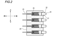
- FIG. 2 is a partial cross-sectional view of the first set group including the optical wiring shown in FIG.
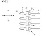
- FIG. 3 is a schematic diagram showing an example of a second set group including the optical wiring shown in FIG.
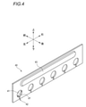
- FIG. 4 is a perspective view of the plate included in the second set group shown in FIG.
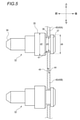
- FIG. 5 is a schematic view showing an example of a state in which two adjacent plates grip the second connecting component.
- FIG. 6 is a schematic diagram showing an example of an optical connection between the first connection component and the second connection component.
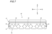
- FIG. 7 is a front view showing another example of the plate.
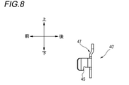
- FIG. 8 is a side view of the plate shown in FIG. 7.
- FIG. 9 is a schematic diagram showing an example of a receptacle corresponding to the plate shown in FIG. 7.
- the purpose of this disclosure is to improve workability when mounting optical wiring including ferrules and receptacles.
- the optical wiring according to one aspect of the present disclosure includes a plurality of first set groups each having a plurality of first connection components in which optical fibers are mounted and arranged in a row, and a plurality of second sets in which optical fibers are mounted and arranged in a row. It has a plurality of second set groups each having a connecting component, a first end face, and a second end face opposite to the first end face, and the plurality of first set groups are connected to the first end face side.
- a receptacle in which the plurality of second set groups are connected to the second end face side is provided, and each of the plurality of first set groups and each of the plurality of second set groups are the first.
- Each of the plurality of first connecting parts and the plurality of the first connecting parts are opposed to each other via the receptacle so that the direction in which the one connecting parts are lined up and the direction in which the second connecting parts are lined up are orthogonal to each other.
- Each of the second connecting parts is optically connected.
- the plurality of first connecting parts are divided into a plurality of first set groups, it is possible to perform replacement work for each first set group. It is also possible to change the order of the wiring by changing the fixing direction of the first set group or changing the fixing position of the first set group. (The same applies to the second connection component.) As a result, workability at the time of mounting the optical wiring can be improved. Further, as another effect that can be expected from the above configuration, it becomes easy to divide a large-capacity optical signal into a small-capacity optical signal and transmit / receive it.
- the plurality of second connecting components are mounted on an optical fiber for transmitting an optical signal traveling from each of the plurality of second connecting components to each of the plurality of first connecting components.
- the plurality of components include two connection components and a second connection component for optical reception on which an optical fiber for transmitting an optical signal traveling from each of the plurality of first connection components to each of the plurality of second connection components is mounted. It is preferable that each of the second set group of the above includes only one of the second connection component for optical transmission and the second connection component for optical reception. According to this configuration, workability can be further improved when mounting on an optical transceiver including an array consisting of a plurality of transmitting units and an array consisting of a plurality of receiving units.
- each of the plurality of second assembly groups has a plate for gripping the plurality of second connection parts.
- the second set group can be formed with a simple structure.
- the plurality of second connecting parts are held on the plate with a clearance between the plurality of second connecting parts and the plate, and the plurality of second connecting parts are held on the plate.
- the plurality of second connecting parts can move in a direction in the main surface of the plate with respect to the plate and in a direction perpendicular to the main surface of the plate, and of an axis along these directions. It is preferable that it can rotate around.
- the second connecting component has a so-called floating structure in a state where the second connecting component is held by the plate.
- the plate and at least a part of the plurality of second connecting parts have conductivity, and the plate is held in a state where the plurality of second connecting parts are held by the plate.
- the partial portion conceals the clearance.
- EMI Electromagnetic Interference
- the plurality of second set groups include a specific second set group and an adjacent second set group adjacent to the specific second set group, and the specific plate of the specific second set group and the said.
- the adjacent plates of the second adjacent assembly group have conductivity, and the specific plate and the adjacent plate overlap each other when viewed from a direction perpendicular to the specific plate and the adjacent plate. It is preferable to have overlapping portions. According to this configuration, it is possible to prevent electromagnetic waves from leaking from the gaps between adjacent plates. As a result, a high effect can be expected as an EMI shield.
- the plate has a plurality of insertion holes for inserting the plurality of second connection parts and slits for connecting the plurality of insertion ports. According to this configuration, it is possible to relieve the press-fitting stress when the second connection component is press-fitted into each insertion hole. Further, by passing the optical fiber mounted on each second connection component through the slit, the second connection component can be inserted into the insertion hole from either side of the plate, and workability is improved.
- the receptacle has a first fitting portion
- the plate has a second fitting portion
- the first fitting portion and the second fitting portion are fitted to each other. Is preferable. This configuration facilitates the positioning of the plate with respect to the receptacle. As a result, workability at the time of mounting can be further improved.
- the plate has a structure bent with respect to the main surface of the plate at at least one side. According to this configuration, the mechanical strength of the plate can be improved. As a result, even if the plate receives the spring pressure derived from the first connection component in the state where the first connection component and the second connection component are connected to the receptacle, the plate has high durability against the spring pressure. It will be.
- the plate preferably includes a diaphragm bead. According to this configuration, the mechanical strength of the plate can be improved. As a result, even if the plate receives the spring pressure derived from the first connection component in the state where the first connection component and the second connection component are connected to the receptacle, the plate has high durability against the spring pressure. It will be.
- the receptacle has an engaging groove
- the plate has an engaging claw that elastically deforms and engages with the engaging groove. According to this configuration, the plate can be easily attached to and detached from the receptacle, so that the workability at the time of mounting can be further improved.
- the optical connection method includes a plurality of first set groups each having a plurality of first connection components in which optical fibers are mounted and arranged in a row, and a plurality of first sets in which optical fibers are mounted and arranged in a row. It has a plurality of second set groups each having two connecting parts, a first end face, and a second end face opposite to the first end face, and the plurality of first set groups are arranged on the first end face side.
- Each of the groups is opposed to each other via the receptacle so that the direction in which the first connecting parts are arranged and the direction in which the second connecting parts are arranged are orthogonal to each other, and the plurality of first units in the receptacle are opposed to each other.
- Each of the connecting parts and each of the plurality of second connecting parts are optically connected.
- the terms “front-back direction”, “left-right direction”, and “vertical direction” may be used.
- the “front-back direction” is a direction perpendicular to the plane to which the first set group is connected (the plane to which the second set group is connected) in the receptacle.
- the direction from the receptacle to the first set group is the "forward direction”
- the direction from the receptacle to the second set group is the "rear direction”.
- the “left-right direction” is a direction perpendicular to the front-rear direction, and is a direction in which a plurality of second connecting parts are lined up in a state where the second assembly group is connected to the receptacle.
- the "vertical direction” is a direction perpendicular to the front-rear direction, and is a direction in which a plurality of first connecting parts are lined up in a state where the first assembly group is connected to the receptacle. It should be noted that these directions are relative to facilitate the understanding of the present disclosure.
- FIG. 1 is a schematic diagram showing an optical wiring 1 according to an embodiment of the present disclosure.
- FIG. 2 is a partial cross-sectional view of the first set group 20 shown in FIG.
- the optical wiring 1 includes a receptacle 10, a first set group 20, and a second set group 30.
- the lower part of FIG. 1 shows a schematic perspective view of the optical wiring 1
- the upper part of FIG. 1 shows the receptacle 10, the first set group 20, and the second set group 30.
- a schematic cross-sectional view when cut in a plane including the vertical direction and the horizontal direction is shown.
- a plurality of first set groups 20 are connected side by side in the left-right direction to the front surface (hereinafter, also referred to as the first end surface) of the receptacle 10.
- a plurality of second assembly groups 30 are connected side by side in the vertical direction to a surface on the rear side of the receptacle 10 (hereinafter, also referred to as a second end surface). That is, each of the plurality of first set groups 20 and each of the plurality of second set groups 30 are orthogonal to each other in the direction in which the first connection component 22 is arranged and the direction in which the second connection component 32 is arranged. It is connected via the receptacle 10.
- the receptacle 10 has N ⁇ M through holes 11 arranged in an N-row (N is an integer of 2 or more) in the vertical direction and an M-row (M is an integer of 2 or more) in the left-right direction.
- the through hole 11 is a hole that penetrates the receptacle 10 in the front-rear direction.
- a split sleeve 12 is held in the through hole 11.
- N and M are not particularly limited as long as they are integers of 2 or more.
- the first set group 20 has N through holes 21 arranged in the vertical direction.
- the first assembly group 20 holds the first connection component 22 on which the optical fiber 23 is mounted in each through hole 21. Further, as shown in FIG. 2, the first connection component 22 has a ferrule 24 and a spring 25.
- the first set group 20 may be a so-called optical connector.
- the second set group 30 has M through holes 31 arranged in the left-right direction.
- the second assembly group 30 holds the second connection component 32 on which the optical fiber 33 is mounted in each through hole 31.
- the internal structure of the second set group 30 is not particularly limited, and may be an optical connector having a structure like that of the first set group 20, or a structure having a plate (see FIG. 3 and the like).
- the rear end of the optical fiber 33 is connected to, for example, a photoelectric conversion module (not shown) connected to an electronic device.
- the optical fiber 33 includes one corresponding to an optical transmission function and one corresponding to an optical reception function.
- the optical fiber 33 corresponding to the optical transmission function transmits an optical signal from the photoelectric conversion module to the optical fiber 23 side.
- the optical fiber 33 corresponding to the optical reception function transmits an optical signal from the optical fiber 23 side to the photoelectric conversion module side.
- Each of the plurality of second set groups 30 has a second connection component 32 for optical transmission on which an optical fiber 33 for optical transmission is mounted, and a second connection component 32 for optical reception on which an optical fiber 33 for optical reception is mounted. It is preferable to include only one of the connecting components.
- the second set group 30 connected to the through hole 11 in the first row from the top in the receptacle 10 includes only the second connection component 32 for optical transmission and is connected to the through hole 11 in the second row from the top.
- the second set group 30 is configured to include only the second connection component 32 for optical reception.
- one first set group 20 includes a first connection component 22 for optical transmission and a first connection component 22 for optical reception.
- FIG. 3 is a schematic diagram showing an example of the second set group 30.
- FIG. 4 is a perspective view of the plate 40 shown in FIG.
- FIG. 5 is a schematic view showing an example of a state in which two adjacent plates 40 (40A, 40B) grip the second connecting component 32.
- the second set group 30 has M second connection parts 32 and a plate 40.
- the second connection component 32 has a ferrule 34, a large diameter portion 35, a small diameter portion 36, and a tail portion 37.
- the plate 40 has M insertion holes 41, M slits 42, a protruding portion 43, and an adjacent portion 44.
- M is 6.
- the second connection component 32 is, for example, a stub.
- the tail 37 is made of a flexible material such as resin.
- the small diameter portion 36 located between the large diameter portion 35 and the tail portion 37 is in a state of being fitted into the insertion hole 41. That is, the second connection component 32 is in a state of being gripped by the plate 40.
- the optical fiber 33 is passed through the slit 42 connecting the insertion hole 41 and one side of the plate 40.
- the large diameter portion 35 may be formed of a flexible material. When the large diameter portion 35 has flexibility, the large diameter portion 35 may be press-fitted into the insertion hole 41.
- the diameter d2 of the large diameter portion 35 and the diameter d4 of the tail portion 37 are larger than the diameter d1 of the insertion hole 41.
- the diameter d3 of the small diameter portion 36 is smaller than the diameter d1.
- the length of the small diameter portion 36 is smaller than the length of the insertion hole 41. Therefore, the second connecting component 32 is held by the plate 40 with a clearance between the plurality of second connecting components 32 and the plate 40. That is, the second connection component 32 is in a state where it can move freely within the clearance range but does not come off the plate 40.
- the second connecting component 32 in the state where the second connecting component 32 is held by the plate 40, the second connecting component 32 has a floating structure, and has a three-axis direction with respect to the plate 40 (direction in the main surface of the plate 40 and the plate). It can move in the direction perpendicular to the main surface of 40) and can rotate around three axes.
- the length such as the diameter d1 is not limited to the above example. That is, the diameter d3 may be the same as the diameter d1. Further, the length of the small diameter portion 36 in the front-rear direction may be the same as the length of the insertion hole 41 in the front-rear direction. Further, the shapes of the large diameter portion 35, the small diameter portion 36, and the tail portion 37 when viewed from the rear side may be circular or polygonal, respectively. When the shape of the large diameter portion 35 is a polygon, the diameter d2 refers to the diameter of the circumscribed circle of the polygon. The same applies to the small diameter portion 36 and the tail portion 37. Further, the second connection component 32 may be fixed to the plate 40 by a conventionally known fixing means such as adhesion or welding.
- the material of the plate 40 is a material having conductivity such as metal or a conductive resin.
- the material of the large diameter portion 35 is also a material having conductivity.
- the plate 40 and the large diameter portion 35 are viewed from a direction perpendicular to the plate 40 in a state where the second connection component 32 is held by the plate 40, the plate 40 and the large diameter portion 35 are located around the insertion hole 41. It has overlapping parts. Further, the position of the insertion hole 41 is located inside the large diameter portion 35. Therefore, the large diameter portion 35 and the plate 40 also function as an EMI shield.
- the tail portion 37 may be formed of a conductive material. In this case, the tail 37 plays a part of the EMI shield.
- the electromagnetic wave is generated from, for example, the above-mentioned electronic device.
- the plate 40A overlaps with the adjacent portion 44 of the plate 40B in the adjacent portion 44 adjacent to the plate 40B.
- the plate 40 is fixed to the receptacle 10 by a predetermined fixing means (for example, a snap fit, a screw, or the like).
- the protruding portion (throttle bead) 43 is a portion where a part of the plate 40 protrudes toward the rear direction.
- the protrusion 43 is formed, for example, by half punching.
- FIG. 6 is a schematic diagram showing an example of an optical connection between the first connection component 22 and the second connection component 32.
- FIG. 6 shows a state in which the first set group 20 shown in FIG. 2 is connected to the first end surface of the receptacle 10, and the second set group 30 shown in FIG. 3 is connected to the second end face of the receptacle 10. ..
- the tip of the ferrule 24 is inserted into the split sleeve 12 of the receptacle 10.
- the tip of the ferrule 34 is inserted into the split sleeve 12.
- the tip portion of the ferrule 24 and the tip portion of the ferrule 34 are optically connected.
- the second connection component 32 has a floating structure with respect to the plate 40, the position of the insertion hole 41 and the split sleeve 12 in the state where the second assembly group 30 is held by the receptacle 10. Even if there is some deviation from the position of, there is little possibility that the optical connection in the split sleeve 12 will be hindered.
- the ferrule 24 and the ferrule 34 are unicent ferrules, respectively.
- the spring 25 applies a rearward urging force to the ferrule 24 at the time of the above optical connection, and prevents a gap from being formed between the ferrule 24 and the ferrule 34. Further, since the spring pressure is applied to the plate 40 by this urging force, a protruding portion 43 is provided to improve the mechanical strength of the plate 40.
- the first set group 20 may have a structure having a plate.
- the second set group 30 may have a structure having a spring without having a plate.
- FIG. 7 is a front view showing another example of the plate 40.
- FIG. 8 is a side view of the plate 40'shown in FIG. 7.
- FIG. 9 is a schematic diagram showing an example of the receptacle 10 ′ corresponding to the plate 40 ′ shown in FIG. 7.
- the plate 40' has M insertion holes 41, M slits 42, engaging claws 45, a second fitting portion 46, and a main surface of the plate 40'. It has a structure bent with respect to (bending structure 47).
- M is 6.
- the receptacle 10'shown in FIG. 9 has N ⁇ M through holes 11 for holding the split sleeves 12 inside, an engaging groove 13, and a first fitting portion 14.
- Engagement claws 45 are provided at both ends of the plate 40', respectively.
- the engaging claw 45 provided on the left end side has a claw that protrudes toward the center from the left end of the plate 40'.
- the engaging claw 45 provided on the right end side has a claw that protrudes toward the center from the right end of the plate 40'.
- At least a portion of the engaging claw 45 is flexible and engages with the engaging groove 13 by a snap fit. That is, the plate 40'and the receptacle 10'are detachably fixed by the engaging claw 45 and the engaging groove 13.
- the plate 40'side may have a groove and the receptacle 10'side may have a claw.
- the second fitting portion 46 is a hole into which the first fitting portion 14 is fitted.
- the first fitting portion 14 is a protrusion that fits into the second fitting portion 46.
- the plate 40'side may have a protrusion and the receptacle 10'side may have a hole.
- the bent structure 47 is a structure in which the upper portion of the plate 40'is bent so as to protrude toward the rear side.
- the bent structure 47 contributes to the improvement of the mechanical strength of the plate 40, similarly to the protrusion 43 described above.
- the plate 40' is provided with a plurality of small slits in addition to the slit 42 connecting the insertion hole 41 and one side (downward side) of the plate 40'.
- the small slit extends from the insertion hole 41 to the left, right, or up, but is not connected to any side of the plate 40'.
- the small slit is provided to further reduce the press-fitting stress when the second connection component 32 is press-fitted into the insertion hole 41.
Landscapes
- Physics & Mathematics (AREA)
- General Physics & Mathematics (AREA)
- Optics & Photonics (AREA)
- Optical Couplings Of Light Guides (AREA)
Abstract
Description
配線の容易性等の観点から、特許文献2に開示されたような複数の単心フェルールを一体化した光コネクタと嵌合可能なレセプタクルを有する光トランシーバへの期待が高まっている。基本的なレセプタクル構造の概念は、例えば、特許文献1に開示されている。しかし、上記光コネクタと接続可能にするために特許文献1のような単心用のレセプタクル構造を複数設けた場合、光コネクタとの接続部分から光電変換モジュールまでの配線が複雑になり易く、実装時の作業性が低下するという問題があった。
上記開示の構成によれば、光配線の実装時の作業性を向上させることができる。
最初に本開示の実施態様を列記して説明する。本開示の一態様に係る光配線は、光ファイバが実装され一列に並んだ複数の第1接続部品をそれぞれ有する複数の第1集合群と、光ファイバが実装され一列に並んだ複数の第2接続部品をそれぞれ有する複数の第2集合群と、第1端面と、前記第1端面とは反対側の第2端面とを有し、前記第1端面側へ前記複数の第1集合群が接続され、前記第2端面側へ前記複数の第2集合群が接続されたレセプタクルと、を備え、前記複数の第1集合群の各々と、前記複数の第2集合群の各々とは、前記第1接続部品の並んでいる方向と前記第2接続部品の並んでいる方向とが直交するように前記レセプタクルを介して対向し、前記レセプタクル内で前記複数の第1接続部品の各々と前記複数の第2接続部品の各々とが光接続されている。すべての第1接続部品を一体とした場合、一体とした第1接続部品をレセプタクルに固定した後は、各配線の順番を入れ替える等の作業が煩雑になる。一方で、上記した構成によれば、複数の第1接続部品が複数の第1集合群に分かれているため、第1集合群ごとに入れ替え作業をすることが可能である。また、第1集合群の固定方向を変えたり、第1集合群の固定位置を変えたりすることによって、各配線の順番を入れ替えることも可能である。(第2接続部品についても同じ。)結果として、光配線の実装時の作業性を向上させることができる。また、上記した構成によって期待できる他の効果として、大容量の光信号を小さい容量の光信号に分割して送受信することが容易になる。
以下、本開示に係る光配線の実施の形態の例を、図面を参照しつつ説明する。以下の説明では、異なる図面であっても同一または相当の要素には同一の符号または名称を付し、重複する説明を適宜省略する。
Claims (12)
- 光ファイバが実装され一列に並んだ複数の第1接続部品をそれぞれ有する複数の第1集合群と、
光ファイバが実装され一列に並んだ複数の第2接続部品をそれぞれ有する複数の第2集合群と、
第1端面と、前記第1端面とは反対側の第2端面とを有し、前記第1端面側へ前記複数の第1集合群が接続され、前記第2端面側へ前記複数の第2集合群が接続されたレセプタクルと、を備え、
前記複数の第1集合群の各々と、前記複数の第2集合群の各々とは、前記第1接続部品の並んでいる方向と前記第2接続部品の並んでいる方向とが直交するように前記レセプタクルを介して対向し、前記レセプタクル内で前記複数の第1接続部品の各々と前記複数の第2接続部品の各々とが光接続されている、
光配線。 - 前記複数の第2接続部品は、前記複数の第2接続部品の各々から前記複数の第1接続部品の各々へ進む光信号を伝送する光ファイバが実装された光送信用第2接続部品と、前記複数の第1接続部品の各々から前記複数の第2接続部品の各々へ進む光信号を伝送する光ファイバが実装された光受信用第2接続部品とを含み、
前記複数の第2集合群の各々は、前記光送信用第2接続部品および前記光受信用第2接続部品のうちいずれか一方のみを含む、
請求項1に記載の光配線。 - 前記複数の第2集合群のそれぞれは、前記複数の第2接続部品を把持するプレートを有する、
請求項1または請求項2に記載の光配線。 - 前記複数の第2接続部品は、前記複数の第2接続部品と前記プレートの間にクリアランスを有した状態で前記プレートに保持され、
前記複数の第2接続部品が前記プレートに保持された状態において、前記複数の第2接続部品は、前記プレートに対して前記プレートの主面内の方向と前記プレートの主面に垂直な方向に移動可能、かつこれらの方向に沿う軸の周りに回転可能である、
請求項3に記載の光配線。 - 前記プレートと、前記複数の第2接続部品における少なくとも一部位とは、導電性を有しており、
前記複数の第2接続部品が前記プレートに保持された状態において、前記プレートと前記複数の第2接続部品とを前記プレートに対して垂直な方向から視た場合、前記一部位は前記クリアランスを隠している、
請求項3または請求項4に記載の光配線。 - 前記複数の第2集合群は、特定第2集合群と前記特定第2集合群に隣接する隣接第2集合群とを含み、
前記特定第2集合群が有する特定プレートと前記隣接第2集合群が有する隣接プレートは、導電性を有したものであり、
前記特定プレートと前記隣接プレートは、前記特定プレートと前記隣接プレートに対して垂直な方向から視た場合、互いに重複する重複部分を有する、
請求項3から請求項5のいずれか一項に記載の光配線。 - 前記プレートは、前記複数の第2接続部品をそれぞれ挿通する複数の挿通孔と前記複数の挿通口とを接続するスリットを有する、
請求項3から請求項6のいずれか一項に記載の光配線。 - 前記レセプタクルは、第1嵌合部を有し、
前記プレートは、第2嵌合部を有し、
前記第1嵌合部と前記第2嵌合部とは互いに嵌合している、
請求項3から請求項7のいずれか一項に記載の光配線。 - 前記プレートは、少なくとも1つの辺において前記プレートの主面に対して曲げられた構造を有する、
請求項3から請求項8のいずれか一項に記載の光配線。 - 前記プレートは、絞りビードを備える、
請求項3から請求項9のいずれか一項に記載の光配線。 - 前記レセプタクルは、係合溝を有し、
前記プレートは、弾性変形して前記係合溝と係合する係合爪を有する、
請求項3から請求項10のいずれか一項に記載の光配線。 - 光ファイバが実装され一列に並んだ複数の第1接続部品をそれぞれ有する複数の第1集合群と、
光ファイバが実装され一列に並んだ複数の第2接続部品をそれぞれ有する複数の第2集合群と、
第1端面と、前記第1端面とは反対側の第2端面とを有し、前記第1端面側へ前記複数の第1集合群が接続され、前記第2端面側へ前記複数の第2集合群が接続されたレセプタクルと、を用いた光接続方法であって、
前記複数の第1集合群の各々と、前記複数の第2集合群の各々とを、前記第1接続部品の並んでいる方向と前記第2接続部品の並んでいる方向とが直交するように前記レセプタクルを介して対向させ、前記レセプタクル内で前記複数の第1接続部品の各々と前記複数の第2接続部品の各々とを光接続する、
光接続方法。
Priority Applications (3)
| Application Number | Priority Date | Filing Date | Title |
|---|---|---|---|
| CN202180053965.5A CN116075758A (zh) | 2020-09-16 | 2021-09-13 | 光布线以及光连接方法 |
| US18/020,164 US12468093B2 (en) | 2020-09-16 | 2021-09-13 | Optical wiring and optical connection method |
| JP2022550549A JP7840265B2 (ja) | 2020-09-16 | 2021-09-13 | 光配線および光接続方法 |
Applications Claiming Priority (2)
| Application Number | Priority Date | Filing Date | Title |
|---|---|---|---|
| JP2020155585 | 2020-09-16 | ||
| JP2020-155585 | 2020-09-16 |
Publications (1)
| Publication Number | Publication Date |
|---|---|
| WO2022059645A1 true WO2022059645A1 (ja) | 2022-03-24 |
Family
ID=80777021
Family Applications (1)
| Application Number | Title | Priority Date | Filing Date |
|---|---|---|---|
| PCT/JP2021/033538 Ceased WO2022059645A1 (ja) | 2020-09-16 | 2021-09-13 | 光配線および光接続方法 |
Country Status (4)
| Country | Link |
|---|---|
| US (1) | US12468093B2 (ja) |
| JP (1) | JP7840265B2 (ja) |
| CN (1) | CN116075758A (ja) |
| WO (1) | WO2022059645A1 (ja) |
Families Citing this family (1)
| Publication number | Priority date | Publication date | Assignee | Title |
|---|---|---|---|---|
| US12468093B2 (en) * | 2020-09-16 | 2025-11-11 | Sumitomo Electric Industries, Ltd. | Optical wiring and optical connection method |
Citations (10)
| Publication number | Priority date | Publication date | Assignee | Title |
|---|---|---|---|---|
| JP2000081541A (ja) * | 1998-06-29 | 2000-03-21 | Yazaki Corp | 光ファイバコネクタ |
| JP2002243985A (ja) * | 2001-02-16 | 2002-08-28 | Fujikura Ltd | 光ファイバテープ心線二次元変換方法および二次元変換光ファイバテープ心線束 |
| JP2004226665A (ja) * | 2003-01-22 | 2004-08-12 | Fujikura Ltd | シャッター付き光コネクタ |
| JP2012530936A (ja) * | 2009-06-17 | 2012-12-06 | コーニング ケーブル システムズ リミテッド ライアビリティ カンパニー | 高速データレート伝送システム用光相互接続 |
| US8403570B2 (en) * | 2008-04-10 | 2013-03-26 | Amphenol Corporation | Plural fiber optic interconnect |
| US20140093211A1 (en) * | 2012-09-28 | 2014-04-03 | Avago Technologies Genenral IP (Singapore) Pte. Ltd. | Optical cross-connect assembly and method |
| US20140308008A1 (en) * | 2013-04-15 | 2014-10-16 | Radiall | Adapter for a multicontact connector with housing and associated multicontact connector |
| JP2017187644A (ja) * | 2016-04-06 | 2017-10-12 | 住友電気工業株式会社 | 光配線接続部材 |
| US20180299625A1 (en) * | 2017-04-13 | 2018-10-18 | Te Connectivity Corporation | Multi-ferrule connector |
| US20200064560A1 (en) * | 2018-08-22 | 2020-02-27 | Hewlett Packard Enterprise Development Lp | Duplex-modulo optical blindmate connector |
Family Cites Families (11)
| Publication number | Priority date | Publication date | Assignee | Title |
|---|---|---|---|---|
| US5009477A (en) * | 1989-05-12 | 1991-04-23 | At&T Bell Laboratories | Optical interconnect arrangement |
| US5185824A (en) * | 1991-10-29 | 1993-02-09 | At&T Bell Laboratories | Optical switch incorporating molded optical waveguide elements |
| JP2616737B2 (ja) * | 1995-01-31 | 1997-06-04 | 日本電気株式会社 | 光クロス結合装置 |
| JP3212063B2 (ja) | 1995-03-08 | 2001-09-25 | 日本電信電話株式会社 | 光レセプタクル |
| JPH10246839A (ja) * | 1997-03-05 | 1998-09-14 | Fujitsu Ltd | 光半導体モジュール |
| US6493480B1 (en) * | 2000-07-31 | 2002-12-10 | Corning Incorporated | Multistage optical cross-connect |
| WO2016121059A1 (ja) * | 2015-01-29 | 2016-08-04 | 株式会社日立製作所 | 光配線装置 |
| US10281668B2 (en) | 2017-07-14 | 2019-05-07 | Senko Advanced Components, Inc. | Ultra-small form factor optical connectors |
| US10788626B1 (en) * | 2019-03-22 | 2020-09-29 | Hewlett Packard Enterprise Development Lp | Reconfigurable optical ferrule carrier mating system |
| US12468093B2 (en) * | 2020-09-16 | 2025-11-11 | Sumitomo Electric Industries, Ltd. | Optical wiring and optical connection method |
| US11726286B2 (en) * | 2021-02-08 | 2023-08-15 | Microsoft Technology Licensing, Llc | Fiber optic cable connector and adapter housing |
-
2021
- 2021-09-13 US US18/020,164 patent/US12468093B2/en active Active
- 2021-09-13 JP JP2022550549A patent/JP7840265B2/ja active Active
- 2021-09-13 WO PCT/JP2021/033538 patent/WO2022059645A1/ja not_active Ceased
- 2021-09-13 CN CN202180053965.5A patent/CN116075758A/zh active Pending
Patent Citations (10)
| Publication number | Priority date | Publication date | Assignee | Title |
|---|---|---|---|---|
| JP2000081541A (ja) * | 1998-06-29 | 2000-03-21 | Yazaki Corp | 光ファイバコネクタ |
| JP2002243985A (ja) * | 2001-02-16 | 2002-08-28 | Fujikura Ltd | 光ファイバテープ心線二次元変換方法および二次元変換光ファイバテープ心線束 |
| JP2004226665A (ja) * | 2003-01-22 | 2004-08-12 | Fujikura Ltd | シャッター付き光コネクタ |
| US8403570B2 (en) * | 2008-04-10 | 2013-03-26 | Amphenol Corporation | Plural fiber optic interconnect |
| JP2012530936A (ja) * | 2009-06-17 | 2012-12-06 | コーニング ケーブル システムズ リミテッド ライアビリティ カンパニー | 高速データレート伝送システム用光相互接続 |
| US20140093211A1 (en) * | 2012-09-28 | 2014-04-03 | Avago Technologies Genenral IP (Singapore) Pte. Ltd. | Optical cross-connect assembly and method |
| US20140308008A1 (en) * | 2013-04-15 | 2014-10-16 | Radiall | Adapter for a multicontact connector with housing and associated multicontact connector |
| JP2017187644A (ja) * | 2016-04-06 | 2017-10-12 | 住友電気工業株式会社 | 光配線接続部材 |
| US20180299625A1 (en) * | 2017-04-13 | 2018-10-18 | Te Connectivity Corporation | Multi-ferrule connector |
| US20200064560A1 (en) * | 2018-08-22 | 2020-02-27 | Hewlett Packard Enterprise Development Lp | Duplex-modulo optical blindmate connector |
Also Published As
| Publication number | Publication date |
|---|---|
| JP7840265B2 (ja) | 2026-04-03 |
| US12468093B2 (en) | 2025-11-11 |
| CN116075758A (zh) | 2023-05-05 |
| JPWO2022059645A1 (ja) | 2022-03-24 |
| US20230288643A1 (en) | 2023-09-14 |
Similar Documents
| Publication | Publication Date | Title |
|---|---|---|
| US10527802B2 (en) | Optical connectors with reversible polarity | |
| US8821039B2 (en) | Optical transceiver having optical receptacle arranged diagonally to longitudinal axis | |
| DE102011077136B4 (de) | Konnektorsystem und Verfahren zum Benutzen eines Konnektorsystems | |
| CN106104337A (zh) | 光学连接器 | |
| US9405086B2 (en) | Organizer tray, fiber-routing assembly, and electro-optical module | |
| CA2714917C (en) | Optical connector and optical connector cable | |
| US12078854B2 (en) | Optical assembly | |
| US20100247040A1 (en) | Ferrule connecting structure | |
| US8905649B2 (en) | Optical fiber terminal fixing member, optical connector, and optical fiber cable with connector | |
| WO2022059645A1 (ja) | 光配線および光接続方法 | |
| US12197013B2 (en) | Optical fiber pitch conversion jig, optical connector, pitch conversion cord, optical conversion box, and pitch conversion method for optical fibers | |
| JP2025072681A (ja) | 光コネクタ | |
| CN101582574B (zh) | 线夹 | |
| JP6992212B1 (ja) | フェルール用ピンクランプ、ガイドピン付きピンクランプ、及び光コネクタ | |
| US20120275753A1 (en) | Fiber assembly with tray feature | |
| EP1879060A1 (en) | Environmentally sealed connector with MT fiber optic locking interface | |
| US5761358A (en) | Optical pin-and-socket connector and process for manufacturing optical pin-and-socket connectors | |
| JPWO2022059645A5 (ja) | ||
| JP2000039537A (ja) | アダプタ | |
| US20110052134A1 (en) | Optical Fiber Termination Holder and Methods for Using the Same | |
| JP2009229997A (ja) | 光ケーブル用アダプタ取付パネル | |
| JP6025693B2 (ja) | 光ファイバテープの分割工具に着脱可能なアタッチメント及び光ファイバテープの分割方法 | |
| US20010036340A1 (en) | Fiber-optics plug connector system as well as connecting clamp for such a plug connector system | |
| JPH05188236A (ja) | 光アレイファイバのガイド装置 | |
| WO2024248140A1 (ja) | 光パネル |
Legal Events
| Date | Code | Title | Description |
|---|---|---|---|
| 121 | Ep: the epo has been informed by wipo that ep was designated in this application |
Ref document number: 21869332 Country of ref document: EP Kind code of ref document: A1 |
|
| ENP | Entry into the national phase |
Ref document number: 2022550549 Country of ref document: JP Kind code of ref document: A |
|
| NENP | Non-entry into the national phase |
Ref country code: DE |
|
| 122 | Ep: pct application non-entry in european phase |
Ref document number: 21869332 Country of ref document: EP Kind code of ref document: A1 |
|
| WWG | Wipo information: grant in national office |
Ref document number: 18020164 Country of ref document: US |