WO2022059593A1 - 熱電変換材料、熱電変換素子、ペルチェ素子、および、熱電変換モジュール、ペルチェモジュール - Google Patents
熱電変換材料、熱電変換素子、ペルチェ素子、および、熱電変換モジュール、ペルチェモジュール Download PDFInfo
- Publication number
- WO2022059593A1 WO2022059593A1 PCT/JP2021/033163 JP2021033163W WO2022059593A1 WO 2022059593 A1 WO2022059593 A1 WO 2022059593A1 JP 2021033163 W JP2021033163 W JP 2021033163W WO 2022059593 A1 WO2022059593 A1 WO 2022059593A1
- Authority
- WO
- WIPO (PCT)
- Prior art keywords
- thermoelectric conversion
- conversion material
- powder
- mass
- boride
- Prior art date
- Legal status (The legal status is an assumption and is not a legal conclusion. Google has not performed a legal analysis and makes no representation as to the accuracy of the status listed.)
- Ceased
Links
Images
Classifications
-
- B—PERFORMING OPERATIONS; TRANSPORTING
- B22—CASTING; POWDER METALLURGY
- B22F—WORKING METALLIC POWDER; MANUFACTURE OF ARTICLES FROM METALLIC POWDER; MAKING METALLIC POWDER; APPARATUS OR DEVICES SPECIALLY ADAPTED FOR METALLIC POWDER
- B22F1/00—Metallic powder; Treatment of metallic powder, e.g. to facilitate working or to improve properties
-
- C—CHEMISTRY; METALLURGY
- C22—METALLURGY; FERROUS OR NON-FERROUS ALLOYS; TREATMENT OF ALLOYS OR NON-FERROUS METALS
- C22C—ALLOYS
- C22C33/00—Making ferrous alloys
- C22C33/02—Making ferrous alloys by powder metallurgy
-
- H—ELECTRICITY
- H02—GENERATION; CONVERSION OR DISTRIBUTION OF ELECTRIC POWER
- H02N—ELECTRIC MACHINES NOT OTHERWISE PROVIDED FOR
- H02N11/00—Generators or motors not provided for elsewhere; Alleged perpetua mobilia obtained by electric or magnetic means
-
- H—ELECTRICITY
- H10—SEMICONDUCTOR DEVICES; ELECTRIC SOLID-STATE DEVICES NOT OTHERWISE PROVIDED FOR
- H10N—ELECTRIC SOLID-STATE DEVICES NOT OTHERWISE PROVIDED FOR
- H10N10/00—Thermoelectric devices comprising a junction of dissimilar materials, i.e. devices exhibiting Seebeck or Peltier effects
- H10N10/80—Constructional details
- H10N10/81—Structural details of the junction
- H10N10/817—Structural details of the junction the junction being non-separable, e.g. being cemented, sintered or soldered
-
- H—ELECTRICITY
- H10—SEMICONDUCTOR DEVICES; ELECTRIC SOLID-STATE DEVICES NOT OTHERWISE PROVIDED FOR
- H10N—ELECTRIC SOLID-STATE DEVICES NOT OTHERWISE PROVIDED FOR
- H10N10/00—Thermoelectric devices comprising a junction of dissimilar materials, i.e. devices exhibiting Seebeck or Peltier effects
- H10N10/80—Constructional details
- H10N10/85—Thermoelectric active materials
- H10N10/851—Thermoelectric active materials comprising inorganic compositions
- H10N10/852—Thermoelectric active materials comprising inorganic compositions comprising tellurium, selenium or sulfur
Definitions
- the present invention relates to a thermoelectric conversion material containing bismuth as a main component, which comprises tellurium and antimony, or at least one of tellurium and selenium and bismuth, a thermoelectric conversion element, a perche element, and a thermoelectric conversion module and a perche module.
- a thermoelectric conversion material containing bismuth as a main component, which comprises tellurium and antimony, or at least one of tellurium and selenium and bismuth, a thermoelectric conversion element, a perche element, and a thermoelectric conversion module and a perche module.
- thermoelectric conversion element made of a thermoelectric conversion material is an electronic element capable of mutually converting heat and electricity, such as the Seebeck effect and the Pelche effect.
- the Zeebeck effect is an effect of converting thermal energy into electrical energy, and is a phenomenon in which an electromotive force is generated when a temperature difference is generated at both ends of a thermoelectric conversion material.
- the Pelche effect is an effect of converting electric energy into heat energy, and when a current is passed through a junction of two types of semiconductors (N-type / P-type) or metal, the junction surface depends on the direction of the current. This is a phenomenon in which heat is absorbed or generated in proportion to the magnitude of an electric current, and a temperature gradient is generated.
- thermoelectric conversion material for example, as shown in Patent Document 1, a material containing at least one of tellurium and selenium and a bismuth compound as a main component has been proposed.
- thermoelectric conversion material containing a bismuth compound as a main component it is mainly used for a Pelche element and a Pelche module utilizing the Pelche effect.
- the Pelche element and Pelche module are used, for example, as a laser diode for optical communication, a wine cooler, and a temperature control device for a compact refrigerator.
- thermoelectric characteristics specific resistance, Seebeck coefficient, etc.
- thermoelectric conversion element thermoelectric conversion material
- the power factor (PF) represented by the following equation (1) and the dimensionless figure of merit represented by the following equation (2) ( ZT) is used.
- the Pelche coefficient ⁇ represented by the following equation (3) is used.
- PF S 2 ⁇ ⁇ ⁇ ⁇ (1)
- ZT S 2 ⁇ T / ⁇ ...
- T absolute temperature (K)
- ⁇ thermal conductivity (W / (m ⁇ K))
- ⁇ S ⁇ T ... (3)
- the Seebeck coefficient ⁇ is a function of the Seebeck coefficient S, and when the Seebeck coefficient S is large, the Perche coefficient ⁇ also becomes large, and the amount of heat absorbed or exhausted from the thermoelectric conversion element (Perche element). The amount of heat increases.
- Patent Document 2 proposes a thermoelectric conversion material in which Ru is added to Bi 2 Te 3 .
- thermoelectric conversion material containing the above-mentioned bismuth compound as a main component it has been desired to improve the strength from the viewpoint of improving the handleability.
- the present invention has been made in view of the above-mentioned circumstances, and is a thermoelectric conversion material having excellent thermoelectric characteristics and strength, and a thermoelectric conversion element, a Pelche element, and a thermoelectric conversion module using this thermoelectric conversion material.
- the purpose is to provide a Pelche module.
- thermoelectric conversion material of the present invention is a bismuth compound containing at least one of tellurium and antimony or tellurium and selenium and bismuth, and at least one metal selected from titanium, zirconium and hafnium. It is characterized by containing a boride containing and.
- thermoelectric conversion material having this configuration since it contains a boride containing at least one metal selected from titanium, zirconium, and hafnium, this boride aggregates at the crystal grain boundary of the bismuth compound as the parent phase. By doing so, the electric conductivity is improved, and it becomes possible to improve the power factor (PF), the Seebeck coefficient, and the Pelche coefficient, which are one of the indexes of the thermoelectric characteristics. Further, since the above-mentioned boride is relatively hard and has high strength, it is possible to improve the strength of the thermoelectric conversion material and suppress the occurrence of cracks during handling.
- PF power factor
- Seebeck coefficient the Seebeck coefficient
- Pelche coefficient which are one of the indexes of the thermoelectric characteristics.
- the bismuth compound may be Bi x Sb 2-x Te 3 (0 ⁇ x ⁇ 0.6).
- the bismuth compound since the bismuth compound is composed of Bi x Sb 2-x Te 3 (0 ⁇ x ⁇ 0.6), it is a p-type thermoelectric conversion material.
- the parent phase is composed of Bi x Sb 2-x Te 3 (0 ⁇ x ⁇ 0.6), which is sufficiently excellent in thermoelectric characteristics and strength.
- the bismuth compound may be Bi 2 Te 3-y Sey (0 ⁇ y ⁇ 3).
- the bismuth compound is Bi 2 Te 3-y Sey and is composed of (0 ⁇ y ⁇ 3)
- it is an n-type thermoelectric conversion material.
- the parent phase is Bi 2 Te 3-y Sey and is composed of (0 ⁇ y ⁇ 3), but the thermoelectric characteristics and strength are sufficiently excellent.
- the boride is one or more selected from TiB 2 , ZrB 2 , and HfB 2 .
- the boride is one or more selected from TiB 2 , ZrB 2 , and HfB 2 , it is possible to surely improve the thermoelectric characteristics and strength.
- thermoelectric conversion material of the present invention it is preferable that the mass ratio of the bismuth compound to the thermoelectric conversion material is in the range of 50 mass% or more and 99.5 mass% or less. In this case, since the mass ratio of the bismuth compound to the thermoelectric conversion material is in the range of 50 mass% or more and 99.5 mass% or less, sufficient thermoelectric characteristics can be ensured.
- the total content of the boride is in the range of 0.5 mass% or more and 15 mass% or less. In this case, since the total content of the boride is in the range of 0.5 mass% or more and 15 mass% or less, it is possible to sufficiently improve the thermoelectric characteristics and strength.
- thermoelectric conversion element of the present invention is characterized by comprising the above-mentioned thermoelectric conversion material and electrodes bonded to one surface and the other surface of the thermoelectric conversion material, respectively. According to the thermoelectric conversion element having this configuration, since the above-mentioned thermoelectric conversion material having excellent thermoelectric characteristics and strength is provided, various characteristics are stabilized. Therefore, the thermoelectric conversion performance is stable and the reliability is excellent.
- the Pelche element of the present invention is characterized by comprising the above-mentioned thermoelectric conversion material and electrodes bonded to one surface and the other surface of the thermoelectric conversion material, respectively. According to the Pelche element having this configuration, since the above-mentioned thermoelectric conversion material having excellent thermoelectric characteristics and strength is provided, various characteristics are stabilized. Therefore, the thermoelectric conversion performance is stable and the reliability is excellent.
- thermoelectric conversion module of the present invention is characterized by comprising the above-mentioned thermoelectric conversion element and a metal plate bonded to the electrodes of the thermoelectric conversion element. According to the thermoelectric conversion module having this configuration, since the thermoelectric conversion element described above is provided, the thermoelectric characteristics and strength of the thermoelectric conversion material are excellent, and various characteristics are stabilized. Therefore, the thermoelectric conversion performance is stable and the reliability is excellent.
- the Pelche module of the present invention is characterized by comprising the above-mentioned Pelche element and a metal plate bonded to the electrode of the Pelche element, respectively. According to the Pelche module having this configuration, since the above-mentioned Pelche element is provided, the thermoelectric conversion material is excellent in thermoelectric characteristics and strength, and various characteristics are stabilized. Therefore, the thermoelectric conversion performance is stable and the reliability is excellent.
- thermoelectric conversion material having excellent thermoelectric characteristics and strength, and a thermoelectric conversion element, a Pelche element, and a thermoelectric conversion module and a Pelche module using the thermoelectric conversion material.
- thermoelectric conversion material thermoelectric conversion material
- thermoelectric conversion element thermoelectric conversion element
- Perche module thermoelectric conversion module
- thermoelectric conversion material the thermoelectric conversion element (Pelche element), and the thermoelectric conversion module (Pelche module), which are the embodiments of the present invention, will be described with reference to the attached drawings.
- thermoelectric conversion element the thermoelectric conversion element
- thermoelectric conversion module the thermoelectric conversion module
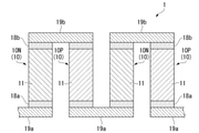
- FIG. 1 shows a thermoelectric conversion material 11 according to an embodiment of the present invention, a thermoelectric conversion element (Pelche element) 10 using the thermoelectric conversion material 11, and a thermoelectric conversion module (Pelche module) 1.
- the thermoelectric conversion element 10 according to the present embodiment includes the thermoelectric conversion material 11 of the present embodiment and electrodes 18a and 18b formed on one surface and the other surface of the thermoelectric conversion material 11. And have.
- the thermoelectric conversion module (Pelche module) 1 includes a plurality of thermoelectric conversion elements 10, and one end side (lower side in FIG. 1) of these thermoelectric conversion elements 10 in the length direction.
- a plurality of thermoelectric conversion elements 10 are electrically connected in series by the metal plate 19a arranged in the metal plate 19a and the metal plate 19b arranged on the other end side (upper side in FIG. 1) of the thermoelectric conversion element 10 in the length direction. It is connected.
- the thermoelectric conversion element 10 includes an n-type thermoelectric conversion element 10N and a p-type thermoelectric conversion element 10P, and these n-type thermoelectric conversion elements 10N and p-type thermoelectric conversion elements 10P are arranged alternately.
- the n-type thermoelectric conversion element 10N and the p-type thermoelectric conversion element 10P are electrically connected in series by the metal plates 19a and 19b.
- Nickel, silver, cobalt, tungsten, molybdenum and the like are used for the electrodes 18a and 18b.
- the electrodes 18a and 18b can be formed by current-carrying sintering, plating, electrodeposition and the like.
- the metal plates 19a and 19b are formed of a metal material having excellent conductivity, for example, a plate material such as copper or aluminum. In this embodiment, a rolled copper plate is used. Further, the thermoelectric conversion element 10 (electrodes 18a and 18b) and the metal plates 19a and 19b can be joined by Ag wax, Ag plating or the like.
- the thermoelectric conversion material 11 of the present embodiment is a sintered body containing tellurium and antimony, or a bismuth compound containing at least one of tellurium and selenium and bismuth as a main component.
- the thermoelectric conversion material 11 is mainly composed of a bismuth compound having a mass ratio of 50 mass% or more and 99.5 mass% or less.
- the bismuth compound is Bi x Sb 2-x Te 3 (0 ⁇ x ⁇ 0.6
- the p-type thermoelectric conversion element 10P can be configured.
- the bismuth compound is Bi 2 Te 3-y Sey (0 ⁇ y ⁇ 3)
- the n-type thermoelectric conversion element 10N can be configured.
- the thermoelectric conversion material 11 of the present embodiment contains a boride containing one or more metals selected from the group 4 elements titanium, zirconium, and hafnium.
- a boride containing one or more metals selected from the group 4 elements titanium, zirconium, and hafnium examples include TiB 2 , ZrB 2 , and HfB 2 . It is preferable that these borides are aggregated at the grain boundaries of the bismuth compound serving as the parent phase.
- the total content of the above-mentioned boride is within the range of 0.5 mass% or more and 15 mass% or less. Further, the lower limit of the total content of the above-mentioned boride is more preferably 1 mass% or more, further preferably 1.5 mass% or more. On the other hand, the upper limit of the total content of the above-mentioned boride is more preferably 12 mass% or less, and further preferably 10 mass% or less.
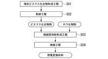
- thermoelectric conversion material 11 Next, the method for manufacturing the thermoelectric conversion material 11 according to the present embodiment will be described with reference to FIGS. 2 and 3.
- a lumpy bismuth compound that is a raw material of a bismuth compound that is a parent phase of a sintered body that is a thermoelectric conversion material 11 is formed.
- the bismuth powder and other raw material powders are weighed and mixed.
- the bismuth compound is Bi x Sb 2-x Te 3 (0 ⁇ x ⁇ 0.6)
- the bismuth powder, the antimony powder, and the tellurium powder are weighed and mixed.
- the bismuth compound is Bi 2 Te 3-y Sey (0 ⁇ y ⁇ 3)
- the bismuth powder and at least one of the tellurium powder and the selenium powder are weighed and mixed.
- this mixed powder is sealed in an ampoule made of quartz glass, heated to a range of 600 ° C. or higher and 800 ° C. or lower, cooled and solidified. As a result, a lumpy bismuth compound is obtained.
- the obtained lumpy bismuth compound is pulverized by a pulverizer to form a bismuth compound powder.
- the average particle size of the bismuth compound powder is preferably in the range of 1 ⁇ m or more and 300 ⁇ m or less.
- the lumpy bismuth compound forming step S01 and the pulverizing step S02 can be omitted.
- the obtained bismuth compound powder is mixed with a boride powder containing one or more metals selected from titanium, zirconium, and hafnium to obtain a sintered raw material powder.
- the content of the boride powder in the sintered raw material powder is preferably in the range of 0.5 mass% or more and 15 mass% or less. Further, it is preferable to use boride powder having a purity of 99 mass% or more. Further, the average particle size of the boride powder is preferably in the range of 1 ⁇ m or more and 100 ⁇ m or less.
- the sintered raw material powder obtained as described above is heated while pressurizing to obtain a sintered body.
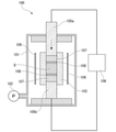
- the sintering apparatus energized sintering apparatus 100
- the sintering device (electric current sintering device 100) shown in FIG. 3 includes, for example, a pressure resistant housing 101, a vacuum pump 102 for depressurizing the inside of the pressure resistant housing 101, and a hollow cylinder arranged inside the pressure resistant housing 101.
- a voltage is applied between the carbon mold 103 of the shape, a pair of electrode portions 105a and 105b for applying a current while pressurizing the sintered raw material powder Q filled in the carbon mold 103, and the pair of electrode portions 105a and 105b.
- the power supply device 106 is provided. Further, a carbon plate 107 and a carbon sheet 108 are arranged between the electrode portions 105a and 105b and the sintered raw material powder Q, respectively. In addition to this, it has a thermometer, a displacement meter, etc. that are not shown. Further, in the present embodiment, the heater 109 is arranged on the outer peripheral side of the carbon mold 103.
- the heaters 109 are arranged on four side surfaces so as to cover the entire outer peripheral side of the carbon mold 103.
- a carbon heater a nichrome wire heater, a molybdenum heater, a Kanthal wire heater, a high frequency heater and the like can be used.
- the sintering raw material powder Q is filled in the carbon mold 103 of the energization sintering device 100 shown in FIG.
- the inside of the carbon mold 103 is, for example, covered with a graphite sheet or a carbon sheet.
- a direct current is passed between the pair of electrode portions 105a and 105b, and a current is passed through the sintered raw material powder Q to raise the temperature by self-heating.
- the movable side electrode portion 105a is moved toward the sintered raw material powder Q, and the sintered raw material powder Q is moved between the fixed side electrode portions 105b and the sintered raw material powder Q at a predetermined pressure. Pressurize. It also heats the heater 109. As a result, the sintered raw material powder Q is sintered by the self-heating of the sintered raw material powder Q, the heat from the heater 109, and the pressurization.
- the sintering conditions in the sintering step S04 are such that the sintering temperature is in the range of 350 ° C. or higher and 550 ° C. or lower, and the holding time at the sintering temperature is 30 minutes or less.
- the pressurized load is within the range of 10 MPa or more and 50 MPa or less.
- the atmosphere inside the pressure-resistant housing 101 may be an inert atmosphere such as an argon atmosphere or a vacuum atmosphere. In the case of a vacuum atmosphere, the pressure should be 5 Pa or less.
- the sintering temperature of the sintered raw material powder Q is less than 350 ° C.
- the bonding between the raw material powders is insufficient and the density of the sintered body becomes low.
- the electrical resistance of the obtained thermoelectric conversion material may increase.
- the strength of the element may be low due to insufficient coupling.
- the sintering temperature of the sintering raw material powder Q exceeds 550 ° C., the decomposition of the bismuth compound proceeds in a short time, and there is a possibility that the composition shifts.
- the sintering temperature in the sintering step S04 is set within the range of 350 ° C. or higher and 550 ° C. or lower.
- the lower limit of the sintering temperature of the sintering raw material powder Q in the sintering step S04 is preferably 360 ° C. or higher, and more preferably 370 ° C. or higher.
- the upper limit of the sintering temperature of the sintering raw material powder Q in the sintering step S04 is preferably 540 ° C. or lower, and more preferably 530 ° C. or lower.
- the holding time at the sintering temperature in the sintering step S04 is set to 30 minutes or less.
- the upper limit of the holding time at the sintering temperature in the sintering step S04 is preferably 20 minutes or less, and more preferably 15 minutes or less.
- the pressurizing load in the sintering step S04 is set within the range of 10 MPa or more and 50 MPa or less.
- the lower limit of the pressurizing load in the sintering step S04 is preferably 15 MPa or more, and more preferably 20 MPa or more.
- the upper limit of the pressurizing load in the sintering step S04 is preferably 45 MPa or less, and more preferably 40 MPa or less.
- thermoelectric conversion material 11 according to the present embodiment is manufactured by each of the above steps.
- thermoelectric conversion material 11 of the present embodiment having the above-described configuration, since a boride containing at least one metal selected from titanium, zirconium, and hafnium is contained, this boride is a mother. By aggregating at the crystal grain boundaries of the bismuth compound as a phase, electrical conductivity is improved, and it becomes possible to improve the power factor (PF), Seebeck coefficient, and Pelche coefficient, which are one of the indexes of thermoelectric characteristics. Further, since the above-mentioned boride is relatively hard and has high strength, it is possible to improve the strength of the thermoelectric conversion material and suppress the occurrence of cracks during handling.
- PF power factor
- Seebeck coefficient Seebeck coefficient
- Pelche coefficient which are one of the indexes of thermoelectric characteristics.
- the bismuth compound constituting the thermoelectric conversion material 11 when the bismuth compound constituting the thermoelectric conversion material 11 is Bi x Sb 2-x Te 3 (0 ⁇ x ⁇ 0.6), it becomes a p-type thermoelectric conversion material. Further, the parent phase is composed of Bi x Sb 2-x Te 3 (0 ⁇ x ⁇ 0.6), which is sufficiently excellent in thermoelectric characteristics and strength.
- the sintering temperature is set within the range of 350 ° C. or higher and 550 ° C. or lower. It is preferable, and it is more preferable that the temperature is in the range of 370 ° C. or higher and 500 ° C. or lower. Further, the total content of boride is preferably in the range of 0.5 mass% or more and 15 mass% or less, and more preferably in the range of 1 mass% or more and 5 mass% or less.
- the bismuth compound constituting the thermoelectric conversion material 11 when the bismuth compound constituting the thermoelectric conversion material 11 is Bi 2 Te 3-y Sey (0 ⁇ y ⁇ 3), it becomes an n-type thermoelectric conversion material. Further, the parent phase is Bi 2 Te 3-y Sey and is composed of (0 ⁇ y ⁇ 3), but the thermoelectric characteristics and strength are sufficiently excellent.
- the sintering temperature is set within the range of 350 ° C. or higher and 550 ° C. or lower. It is preferable, and it is more preferable that the temperature is in the range of 400 ° C. or higher and 530 ° C. or lower. Further, the total content of boride is preferably in the range of 0.5 mass% or more and 15 mass% or less, and more preferably in the range of 1 mass% or more and 5 mass% or less.
- thermoelectric characteristics and strength when the total content of the above-mentioned boride is within the range of 0.5 mass% or more and 15 mass% or less, the thermoelectric characteristics and strength can be sufficiently improved. Further, in the present embodiment, when the above-mentioned boride is one or more selected from TiB 2 , ZrB 2 , and HfB 2 , it is possible to surely improve the thermoelectric characteristics and strength. ..
- thermoelectric conversion material 11 when the mass ratio of the bismuth compound to the thermoelectric conversion material 11 is within the range of 50 mass% or more and 99.5 mass% or less, sufficient thermoelectric characteristics can be ensured.
- thermoelectric conversion element (Pelche element) 10 and the thermoelectric conversion module (Pelche module) 1 of the present embodiment are provided with the above-mentioned thermoelectric conversion material 11 having excellent thermoelectric characteristics and strength, various characteristics are stable. Will be done. Therefore, the thermoelectric conversion performance is stable and the reliability is excellent.
- thermoelectric conversion module having a structure as shown in FIG. 1, but the present invention is not limited to this, and if the thermoelectric conversion material of the present invention is used, an electrode or an electrode can be used. There are no particular restrictions on the structure and arrangement of the terminals.
- the bismuth compound when the bismuth compound is Bi x Sb 2-x Te 3 (0 ⁇ x ⁇ 0.6), from Bi x Sb 2-x Te 3 (0 ⁇ x ⁇ 0.6).
- the bismuth compound powder is mixed with the bismuth powder to form a sintered raw material powder, the present invention is not limited to this, and the xBi 2 Te 3 powder and the (2-x) Sb 2 Te 3 powder are not limited thereto. And bismuth powder may be mixed to obtain sintered raw material powder.
- the sintering is performed using the sintering apparatus (energized sintering apparatus 100) shown in FIG. 3, but the present invention is not limited to this, and the sintering raw material is indirectly used.
- a method of pressurizing and sintering while heating for example, hot pressing, HIP (Hot Isostatic Pressing), or the like may be used.
- Example 1 the thermoelectric characteristics of the thermoelectric conversion material containing Bi x Sb 2-x Te 3 (0 ⁇ x ⁇ 0.6) as a main component were evaluated.
- Bi powder with a purity of 99.999 mass% (average particle size 2 mm)
- Te powder with a purity of 99.999 mass% (particle size 2 mm)
- It was placed in a quartz container, Ar gas was sealed inside to prevent oxidation, and the mixture was heated at 700 ° C. for 5 hours.
- a lumpy bismuth compound having the composition shown in Table 1 was obtained.
- this lumpy bismuth compound was finely crushed in a mortar and classified to obtain a lumpy bismuth compound powder having an average particle size of 100 ⁇ m.
- Example 1 of the present invention the boride powder (purity 99.9 mass%, average particle size 3 ⁇ m) shown in Table 1 is prepared. This was weighed so as to have the content shown in Table 1, and the massive bismuth compound powder and the boride powder were mixed to obtain a sintered raw material powder. The obtained sintered raw material powder was filled in a carbon mold whose inside was covered with a carbon sheet. Then, the sintering apparatus (energized sintering apparatus 100) shown in FIG. 3 was used for energization sintering under the conditions of a sintering temperature of 380 ° C., a holding time of 5 minutes at the sintering temperature, and a pressurizing pressure of 30 MPa.
- thermoelectric conversion material having the composition shown in Table 1 was obtained.
- the thermoelectric conversion materials obtained as described above were evaluated for specific resistance R, Seebeck coefficient S, power factor PF, thermal conductivity ⁇ , dimensionless figure of merit ZT, and Perche coefficient ⁇ at various temperatures. The evaluation results are shown in Table 1.
- the thermal conductivity ⁇ was obtained from the thermal diffusivity ⁇ density ⁇ specific heat capacity.
- the thermal diffusivity and specific heat were measured using an Xe flash analyzer (LFA467 HyperFlash, manufactured by NETZSCH), and the density was measured using the Archimedes method. The measurement was carried out at 27 ° C, 50 ° C, 100 ° C, 150 ° C and 200 ° C.
- the dimensionless figure of merit ZT was obtained from the following equation (2).
- Example 1 of the present invention to which boride was added, the absolute values of Seebeck coefficient S, power factor PF, and Pelche coefficient were higher at various temperatures than in Comparative Example 1 to which boride was not added, and thermoelectric characteristics (thermoelectric conversion) were obtained. It is confirmed that the efficiency) is excellent.
- Example 2 the thermoelectric characteristics of the thermoelectric conversion material containing Bi 2 Te 3-y Sey (0 ⁇ y ⁇ 3) as a main component were evaluated.
- Bi powder with a purity of 99.999 mass% average particle size 2 mm
- Te powder with a purity of 99.999 mass% particle size 2 mm
- Se powder with a purity of 99.999 mass% severe mm pellets
- a lumpy bismuth compound having the composition shown in Table 2 was obtained.
- this lumpy bismuth compound was finely crushed in a mortar and classified to obtain a lumpy bismuth compound powder having an average particle size of 100 ⁇ m.
- Example 2 of the present invention the boride powder (purity 99.9 mass%, average particle size 3 ⁇ m) shown in Table 2 is prepared. This was weighed so as to have the content shown in Table 2, and the massive bismuth compound powder and the boride powder were mixed to obtain a sintered raw material powder. The obtained sintered raw material powder was filled in a carbon mold whose inside was covered with a carbon sheet. Then, the sintering apparatus (energized sintering apparatus 100) shown in FIG. 3 was used for energization sintering under the conditions of a sintering temperature of 410 ° C., a holding time at the sintering temperature of 5 minutes, and a pressurizing pressure of 30 MPa.
- thermoelectric conversion material having the composition shown in Table 2 was obtained.
- the resistivity R, the Seebeck coefficient S, the power factor PF, the thermal conductivity ⁇ , the dimensionless figure of merit ZT, and the Pelche coefficient at various temperatures are the same as in Example 1.
- Example 2 of the present invention to which boride was added, the absolute values of Seebeck coefficient S, power factor PF, and Pelche coefficient were higher at various temperatures than in Comparative Example 2 to which boride was not added, and thermoelectric characteristics (thermoelectric conversion) were obtained. It is confirmed that the efficiency) is excellent.
- Example 3 In this Example 3, the thermoelectric conversion materials (Bi x Sb 2-x Te 3 (0 ⁇ x ⁇ 0.6)) of the present invention Example 1 and Comparative Example 1 obtained in Example 1 were obtained in Example 2. The strength of the thermoelectric conversion material (Bi 2 Te 3-y Sey (0 ⁇ y ⁇ 3)) of the second invention example 2 and the comparative example 2 was evaluated. The above-mentioned thermoelectric conversion material was subjected to a three-point bending test at temperatures of 27 ° C. and 200 ° C., respectively, and the bending strength was measured. The measurement results are shown in Table 3.
- the test jig was a 3-point bending jig made of SiC, and the distance between the fulcrums was 12 mm.
- the test atmosphere was an atmosphere at 27 ° C. and an Ar atmosphere at 200 ° C.
- the displacement rate of the crosshead was 0.5 mm / min, the temperature rising rate was 20 ° C./min, and the crosshead was held for 15 minutes after reaching the test temperature, and then a three-point bending test was performed.
- the bending strength (MPa) was determined from the maximum load at the time of breaking by using the following formula.
- Example 1 of the present invention in which a boride is added to Bi x Sb 2-x Te 3 (0 ⁇ x ⁇ 0.6), the bending strength is higher at both temperatures of 27 ° C. and 200 ° C. as compared with Comparative Example 1. Improved.
- Example 2 of the present invention in which a boride was added to Bi 2 Te 3-y Sey (0 ⁇ y ⁇ 3), the bending strength at 27 ° C. was improved as compared with Comparative Example 2.
- Te powder with a purity of 99.999 mass% (particle size 2 mm) It was placed in a quartz container, Ar gas was sealed inside to prevent oxidation, and the mixture was heated at 700 ° C. for 5 hours.
- a lumpy bismuth compound having the composition shown in Table 4 was obtained.
- this lumpy bismuth compound was finely crushed in a mortar and classified to obtain a lumpy bismuth compound powder having an average particle size of 100 ⁇ m.
- the boride powder (purity 99.9 mass%, average particle size 3 ⁇ m) shown in Table 4 is prepared. This was weighed so as to have the content shown in Table 4, and the massive bismuth compound powder and the boride powder were mixed to obtain a sintered raw material powder. The obtained sintered raw material powder was filled in a carbon mold whose inside was covered with a carbon sheet. Then, the sintering device (energized sintering device 100) shown in FIG. 3 was used for current-carrying sintering under the conditions of a sintering temperature of 470 to 480 ° C., a holding time of 5 minutes at the sintering temperature, and a pressurizing pressure of 30 MPa.
- thermoelectric conversion material having the composition shown in Table 1 was obtained.
- the resistivity R, the Seebeck coefficient S, the power factor PF, the thermal conductivity ⁇ , the dimensionless figure of merit ZT, and the Pelche coefficient at various temperatures are the same as in Example 1.
- the boride powder (purity 99.9 mass%, average particle size 3 ⁇ m) shown in Table 5 is prepared. This was weighed so as to have the content shown in Table 5, and the massive bismuth compound powder and the boride powder were mixed to obtain a sintered raw material powder. The obtained sintered raw material powder was filled in a carbon mold whose inside was covered with a carbon sheet. Then, the sintering apparatus (energized sintering apparatus 100) shown in FIG. 3 was used for energization sintering under the conditions of a sintering temperature of 500 to 520 ° C., a holding time of 5 minutes at the sintering temperature, and a pressurizing pressure of 30 MPa.
- thermoelectric conversion material having the composition shown in Table 5 was obtained.
- the resistivity R, the Seebeck coefficient S, the power factor PF, the thermal conductivity ⁇ , the dimensionless figure of merit ZT, and the Pelche coefficient at various temperatures are the same as in Example 1.
- Example 21 and 22 of the present invention it is confirmed that in Examples 21 and 22 of the present invention to which boride is added, the Seebeck coefficient S and the Pelche coefficient ⁇ are superior to those of Comparative Example 21 to which boride is not added. Further, comparing Examples 21 and 22 of the present invention, it is confirmed that the Seebeck coefficient S and the Pelche coefficient ⁇ are further excellent as the content of boride increases. Further, it is confirmed that the Seebeck coefficient S and the Pelche coefficient ⁇ are superior to those of Examples 21 and 22 of the present invention in which the sintering temperature is set higher than those of Example 2 of the present invention of Example 2. In particular, in Example 21 of the present invention containing boride, it is confirmed that the power factor PF is excellent in addition to the Seebeck coefficient S and the Pelche coefficient ⁇ in the relatively low temperature range of ⁇ 73 ° C. to 50 ° C.
- Example 6 (Example 6)
- a three-point bending test was carried out on the above-mentioned thermoelectric conversion material at temperatures of 27 ° C. and 200 ° C., respectively, and the bending strength was measured. The measurement results are shown in Table 6.
- thermoelectric conversion material having excellent thermoelectric characteristics and strength, and a thermoelectric conversion element, a Pelche element, a thermoelectric conversion module, and a Pelche module using this thermoelectric conversion material. It was confirmed that.
- Thermoelectric conversion module (Pelche module) 10 Thermoelectric conversion element (Pelche element) 11 Thermoelectric conversion material 18a, 18b Electrodes 19a, 19b Metal plate
Landscapes
- Chemical & Material Sciences (AREA)
- Engineering & Computer Science (AREA)
- Materials Engineering (AREA)
- Mechanical Engineering (AREA)
- Metallurgy (AREA)
- Organic Chemistry (AREA)
- Inorganic Chemistry (AREA)
- Powder Metallurgy (AREA)
Abstract
本発明の熱電変換材料は、テルルおよびアンチモン、あるいは、テルルおよびセレンの少なくとも一方とビスマスとを含むビスマス化合物と、チタン、ジルコニウム、ハフニウムから選択される少なくとも一種の金属を含むホウ化物と、を含有することを特徴とする。前記ホウ化物が、TiB2,ZrB2,HfB2から選択される一種又は二種以上であることが好ましい。
Description
この発明は、テルルおよびアンチモン、あるいは、テルルおよびセレンの少なくとも一方とビスマスとを含むビスマス化合物を主成分とする熱電変換材料、熱電変換素子、ペルチェ素子、および、熱電変換モジュール、ペルチェモジュールに関するものである。
本願は、2020年9月16日に、日本に出願された特願2020-155147号、および2021年8月19日に、日本に出願された特願2021-134026号に基づき優先権を主張し、その内容をここに援用する。
本願は、2020年9月16日に、日本に出願された特願2020-155147号、および2021年8月19日に、日本に出願された特願2021-134026号に基づき優先権を主張し、その内容をここに援用する。
熱電変換材料からなる熱電変換素子は、ゼーベック効果、ペルチェ効果といった、熱と電気とを相互に変換可能な電子素子である。
ゼーベック効果は、熱エネルギーを電気エネルギーに変換する効果であり、熱電変換材料の両端に温度差を生じさせると起電力が発生する現象である。
一方、ペルチェ効果は、電気エネルギーを熱エネルギーに変換する効果であり、2種類の半導体(N型/P型)または金属を接合したものに電流を流すと、電流の方向に応じて、接合面に電流の大きさに比例した熱量の吸収又は発生が起こり、温度勾配が発生する現象である。
ゼーベック効果は、熱エネルギーを電気エネルギーに変換する効果であり、熱電変換材料の両端に温度差を生じさせると起電力が発生する現象である。
一方、ペルチェ効果は、電気エネルギーを熱エネルギーに変換する効果であり、2種類の半導体(N型/P型)または金属を接合したものに電流を流すと、電流の方向に応じて、接合面に電流の大きさに比例した熱量の吸収又は発生が起こり、温度勾配が発生する現象である。
上述の熱電変換材料として、例えば特許文献1に示すように、テルルおよびセレンの少なくとも一方とビスマスとを含むビスマス化合物を主成分としたものが提案されている。
なお、上述のビスマス化合物を主成分とする熱電変換材料においては、主に、ペルチェ効果を利用したペルチェ素子およびペルチェモジュールに用いられている。ペルチェ素子およびペルチェモジュールは、例えば、光通信用のレーザダイオード、ワインクーラーや小型冷蔵庫の温調装置として使用されている。なお、小型冷蔵庫などの温調装置として使用する場合には、0℃以下の温度帯域での熱電特性(比抵抗、ゼーベック係数など)が重要となる場合がある。
なお、上述のビスマス化合物を主成分とする熱電変換材料においては、主に、ペルチェ効果を利用したペルチェ素子およびペルチェモジュールに用いられている。ペルチェ素子およびペルチェモジュールは、例えば、光通信用のレーザダイオード、ワインクーラーや小型冷蔵庫の温調装置として使用されている。なお、小型冷蔵庫などの温調装置として使用する場合には、0℃以下の温度帯域での熱電特性(比抵抗、ゼーベック係数など)が重要となる場合がある。
上述の熱電変換素子(熱電変換材料)の特性を表す指標として、例えば以下の(1)式で表されるパワーファクター(PF)や、以下の(2)式で表される無次元性能指数(ZT)が用いられている。また、ペルチェ素子の特性を表す指標として、以下の(3)式で表されるペルチェ係数πが用いられている。
PF=S2σ・・・(1)
但し、S:ゼーベック係数(V/K)、σ:電気伝導率(S/m)
ZT=S2σT/κ・・・(2)
但し、T:絶対温度(K)、κ:熱伝導率(W/(m×K))
π=S×T・・・(3)
但し、T:絶対温度(K)、S:ゼーベック係数(V/K)
PF=S2σ・・・(1)
但し、S:ゼーベック係数(V/K)、σ:電気伝導率(S/m)
ZT=S2σT/κ・・・(2)
但し、T:絶対温度(K)、κ:熱伝導率(W/(m×K))
π=S×T・・・(3)
但し、T:絶対温度(K)、S:ゼーベック係数(V/K)
上述の(3)式に示すように、ペルチェ係数πはゼーベック係数Sの関数となっており、ゼーベック係数Sが大きいとペルチェ係数πも大きくなり、熱電変換素子(ペルチェ素子)の吸熱量または排熱量が大きくなる。
ここで、ビスマス化合物を主成分とする熱電変換材料の特性を向上させる手段として、特許文献2には、Bi2Te3にRuを添加した熱電変換材料が提案されている。
ここで、ビスマス化合物を主成分とする熱電変換材料の特性を向上させる手段として、特許文献2には、Bi2Te3にRuを添加した熱電変換材料が提案されている。
ところで、特許文献2に示すように、Bi2Te3にRuを添加することによって、特性を向上させることが可能であるが、Ruは白金族元素のひとつであり、資源量も少なく、高価である。このため、製造コストが非常に高く、様々な用途において使用することが困難であった。
また、上述のビスマス化合物を主成分とする熱電変換材料においては、取り扱い性を向上させる観点から、強度を向上させることが望まれていた。
また、上述のビスマス化合物を主成分とする熱電変換材料においては、取り扱い性を向上させる観点から、強度を向上させることが望まれていた。
この発明は、前述した事情に鑑みてなされたものであって、熱電特性、強度に優れた熱電変換材料、および、この熱電変換材料を用いた熱電変換素子、ペルチェ素子、および、熱電変換モジュール、ペルチェモジュールを提供することを目的とする。
上記課題を解決するために、本発明の熱電変換材料は、テルルおよびアンチモン、あるいは、テルルおよびセレンの少なくとも一方とビスマスとを含むビスマス化合物と、チタン、ジルコニウム、ハフニウムから選択される少なくとも一種の金属を含むホウ化物と、を含有することを特徴としている。
この構成の熱電変換材料によれば、チタン、ジルコニウム、ハフニウムから選択される少なくとも一種の金属を含むホウ化物を含有しているので、このホウ化物が母相となるビスマス化合物の結晶粒界に凝集することによって、電気伝導性が向上し、熱電特性の指標の一つであるパワーファクター(PF)、ゼーベック係数、ペルチェ係数を向上させることが可能となる。
さらに、上述のホウ化物は比較的硬く、強度が高いため、熱電変換材料の強度を向上させることができ、取り扱い時における割れの発生を抑制することが可能となる。
さらに、上述のホウ化物は比較的硬く、強度が高いため、熱電変換材料の強度を向上させることができ、取り扱い時における割れの発生を抑制することが可能となる。
ここで、本発明の熱電変換材料においては、前記ビスマス化合物は、BixSb2―xTe3(0<x≦0.6)であってもよい。
この場合、前記ビスマス化合物は、BixSb2―xTe3(0<x≦0.6)で構成されているので、p型の熱電変換材料となる。また、母相がBixSb2―xTe3(0<x≦0.6)で構成されることになるが、熱電特性、強度に十分に優れている。
この場合、前記ビスマス化合物は、BixSb2―xTe3(0<x≦0.6)で構成されているので、p型の熱電変換材料となる。また、母相がBixSb2―xTe3(0<x≦0.6)で構成されることになるが、熱電特性、強度に十分に優れている。
また、本発明の熱電変換材料においては、前記ビスマス化合物は、Bi2Te3―ySeyで(0≦y≦3)であってもよい。
この場合、前記ビスマス化合物は、Bi2Te3―ySeyで(0≦y≦3)で構成されているので、n型の熱電変換材料となる。また、母相がBi2Te3―ySeyで(0≦y≦3)で構成されることになるが、熱電特性、強度に十分に優れている。
この場合、前記ビスマス化合物は、Bi2Te3―ySeyで(0≦y≦3)で構成されているので、n型の熱電変換材料となる。また、母相がBi2Te3―ySeyで(0≦y≦3)で構成されることになるが、熱電特性、強度に十分に優れている。
また、本発明の熱電変換材料においては、前記ホウ化物が、TiB2,ZrB2,HfB2から選択される一種又は二種以上であることが好ましい。
この場合、前記ホウ化物が、TiB2,ZrB2,HfB2から選択される一種又は二種以上とされているので、確実に、熱電特性、強度を向上させることが可能となる。
この場合、前記ホウ化物が、TiB2,ZrB2,HfB2から選択される一種又は二種以上とされているので、確実に、熱電特性、強度を向上させることが可能となる。
また、本発明の熱電変換材料においては、前記熱電変換材料に対する前記ビスマス化合物の質量割合が、50mass%以上99.5mass%以下の範囲内とされていることが好ましい。
この場合、前記熱電変換材料に対する前記ビスマス化合物の質量割合が、50mass%以上99.5mass%以下の範囲内とされているので、十分な熱電特性を確保することができる。
この場合、前記熱電変換材料に対する前記ビスマス化合物の質量割合が、50mass%以上99.5mass%以下の範囲内とされているので、十分な熱電特性を確保することができる。
さらに、本発明の熱電変換材料においては、前記ホウ化物の合計含有量が0.5mass%以上15mass%以下の範囲内とされていることが好ましい。
この場合、前記ホウ化物の合計含有量が0.5mass%以上15mass%以下の範囲内とされているので、熱電特性、強度を十分に向上させることが可能となる。
この場合、前記ホウ化物の合計含有量が0.5mass%以上15mass%以下の範囲内とされているので、熱電特性、強度を十分に向上させることが可能となる。
本発明の熱電変換素子は、上述の熱電変換材料と、前記熱電変換材料の一方の面および他方の面にそれぞれ接合された電極と、を備えたことを特徴としている。
この構成の熱電変換素子によれば、熱電特性、強度に優れた上述の熱電変換材料を備えているので、各種特性が安定することになる。よって、熱電変換性能が安定し、信頼性に優れている。
この構成の熱電変換素子によれば、熱電特性、強度に優れた上述の熱電変換材料を備えているので、各種特性が安定することになる。よって、熱電変換性能が安定し、信頼性に優れている。
本発明のペルチェ素子は、上述の熱電変換材料と、前記熱電変換材料の一方の面および他方の面にそれぞれ接合された電極と、を備えたことを特徴としている。
この構成のペルチェ素子によれば、熱電特性、強度に優れた上述の熱電変換材料を備えているので、各種特性が安定することになる。よって、熱電変換性能が安定し、信頼性に優れている。
この構成のペルチェ素子によれば、熱電特性、強度に優れた上述の熱電変換材料を備えているので、各種特性が安定することになる。よって、熱電変換性能が安定し、信頼性に優れている。
本発明の熱電変換モジュールは、上述の熱電変換素子と、前記熱電変換素子の前記電極にそれぞれ接合された金属板と、を備えたことを特徴としている。
この構成の熱電変換モジュールによれば、上述の熱電変換素子を備えているので、熱電変換材料の熱電特性、強度に優れており、各種特性が安定することになる。よって、熱電変換性能が安定し、信頼性に優れている。
この構成の熱電変換モジュールによれば、上述の熱電変換素子を備えているので、熱電変換材料の熱電特性、強度に優れており、各種特性が安定することになる。よって、熱電変換性能が安定し、信頼性に優れている。
本発明のペルチェモジュールは、上述のペルチェ素子と、前記ペルチェ素子の前記電極にそれぞれ接合された金属板と、を備えたことを特徴としている。
この構成のペルチェモジュールによれば、上述のペルチェ素子を備えているので、熱電変換材料の熱電特性、強度に優れており、各種特性が安定することになる。よって、熱電変換性能が安定し、信頼性に優れている。
この構成のペルチェモジュールによれば、上述のペルチェ素子を備えているので、熱電変換材料の熱電特性、強度に優れており、各種特性が安定することになる。よって、熱電変換性能が安定し、信頼性に優れている。
本発明によれば、熱電特性、強度に優れた熱電変換材料、および、この熱電変換材料を用いた熱電変換素子、ペルチェ素子、および、熱電変換モジュール、ペルチェモジュールを提供することが可能となる。
以下に、本発明の実施形態である熱電変換材料、熱電変換素子(ペルチェ素子)、および、熱電変換モジュール(ペルチェモジュール)について、添付した図面を参照して説明する。なお、以下に示す各実施形態は、発明の趣旨をより良く理解させるために具体的に説明するものであり、特に指定のない限り、本発明を限定するものではない。また、以下の説明で用いる図面は、本発明の特徴をわかりやすくするために、便宜上、要部となる部分を拡大して示している場合があり、各構成要素の寸法比率などが実際と同じであるとは限らない。
図1に、本発明の実施形態である熱電変換材料11、および、この熱電変換材料11を用いた熱電変換素子(ペルチェ素子)10、および、熱電変換モジュール(ペルチェモジュール)1を示す。
本実施形態に係る熱電変換素子10は、図1に示すように、本実施形態である熱電変換材料11と、この熱電変換材料11の一方の面および他方の面に形成された電極18a,18bと、を備えている。
本実施形態に係る熱電変換素子10は、図1に示すように、本実施形態である熱電変換材料11と、この熱電変換材料11の一方の面および他方の面に形成された電極18a,18bと、を備えている。
そして、熱電変換モジュール(ペルチェモジュール)1は、図1に示すように、複数の熱電変換素子10を備えており、これらの熱電変換素子10の長さ方向の一端側(図1において下側)に配設された金属板19a、および、熱電変換素子10の長さ方向の他端側(図1において上側)に配設された金属板19bによって、複数の熱電変換素子10が電気的に直列接続されている。
なお、熱電変換素子10は、n型熱電変換素子10Nとp型熱電変換素子10Pと、を備えており、これらn型熱電変換素子10Nとp型熱電変換素子10Pが交互に配列されている。そして、金属板19a,19bによって、これらn型熱電変換素子10Nとp型熱電変換素子10Pとが電気的に直列接続されている。
なお、熱電変換素子10は、n型熱電変換素子10Nとp型熱電変換素子10Pと、を備えており、これらn型熱電変換素子10Nとp型熱電変換素子10Pが交互に配列されている。そして、金属板19a,19bによって、これらn型熱電変換素子10Nとp型熱電変換素子10Pとが電気的に直列接続されている。
電極18a,18bは、ニッケル、銀、コバルト、タングステン、モリブデン等が用いられる。この電極18a,18bは、通電焼結、めっき、電着等によって形成することができる。
金属板19a,19bは、導電性に優れた金属材料、例えば、銅やアルミニウムなどの板材から形成されている。本実施形態では、銅の圧延板を用いている。また、熱電変換素子10(電極18a,18b)と金属板19a,19bとは、AgろうやAgメッキ等によって接合することができる。
金属板19a,19bは、導電性に優れた金属材料、例えば、銅やアルミニウムなどの板材から形成されている。本実施形態では、銅の圧延板を用いている。また、熱電変換素子10(電極18a,18b)と金属板19a,19bとは、AgろうやAgメッキ等によって接合することができる。
そして、本実施形態である熱電変換材料11は、テルルおよびアンチモン、あるいは、テルルおよびセレンの少なくとも一方とビスマスとを含むビスマス化合物を主成分とした焼結体とされている。本実施形態では、熱電変換材料11は、ビスマス化合物の質量割合が50mass%以上99.5mass%以下と主成分とされている。
ここで、ビスマス化合物がBixSb2―xTe3(0<x≦0.6)である場合には、p型熱電変換素子10Pを構成することが可能となる。
一方、ビスマス化合物がBi2Te3―ySeyで(0≦y≦3)である場合には、n型熱電変換素子10Nを構成することが可能となる。
ここで、ビスマス化合物がBixSb2―xTe3(0<x≦0.6)である場合には、p型熱電変換素子10Pを構成することが可能となる。
一方、ビスマス化合物がBi2Te3―ySeyで(0≦y≦3)である場合には、n型熱電変換素子10Nを構成することが可能となる。
そして、本実施形態である熱電変換材料11においては、第4族元素であるチタン、ジルコニウム、ハフニウムから選択される一種又は二種以上の金属を含むホウ化物を含有している。上述のホウ化物としては、TiB2、ZrB2、HfB2が挙げられる。なお、これらのホウ化物は、母相となるビスマス化合物の粒界に凝集していることが好ましい。
ここで、本実施形態においては、上述のホウ化物の合計含有量が0.5mass%以上15mass%以下の範囲内とされていることが好ましい。
また、上述のホウ化物の合計含有量の下限は1mass%以上であることがより好ましく、1.5mass%以上であることがさらに好ましい。一方、上述のホウ化物の合計含有量の上限は12mass%以下であることがより好ましく、10mass%以下であることがさらに好ましい。
また、上述のホウ化物の合計含有量の下限は1mass%以上であることがより好ましく、1.5mass%以上であることがさらに好ましい。一方、上述のホウ化物の合計含有量の上限は12mass%以下であることがより好ましく、10mass%以下であることがさらに好ましい。
次に、本実施形態である熱電変換材料11の製造方法について、図2および図3を参照して説明する。
(塊状ビスマス化合物形成工程S01)
まず、熱電変換材料11である焼結体の母相となるビスマス化合物の原料となる塊状ビスマス化合物を形成する。
塊状ビスマス化合物形成工程S01においては、ビスマス粉と他の原料粉とをそれぞれ秤量して混合する。
例えば、ビスマス化合物がBixSb2―xTe3(0<x≦0.6)である場合には、ビスマス粉とアンチモン粉とテルル粉とをそれぞれ計量して混合する。
また、ビスマス化合物がBi2Te3―ySeyで(0≦y≦3)である場合には、ビスマス粉と、テルル粉およびセレン粉の少なくとも一方とをそれぞれ計量して混合する。
そして、TeやSeは蒸気圧が高いので、この混合粉を、石英ガラス製のアンプルに封入し、600℃以上800℃以下の範囲内にまで加熱し、冷却して固化させる。これにより、塊状ビスマス化合物を得る。
まず、熱電変換材料11である焼結体の母相となるビスマス化合物の原料となる塊状ビスマス化合物を形成する。
塊状ビスマス化合物形成工程S01においては、ビスマス粉と他の原料粉とをそれぞれ秤量して混合する。
例えば、ビスマス化合物がBixSb2―xTe3(0<x≦0.6)である場合には、ビスマス粉とアンチモン粉とテルル粉とをそれぞれ計量して混合する。
また、ビスマス化合物がBi2Te3―ySeyで(0≦y≦3)である場合には、ビスマス粉と、テルル粉およびセレン粉の少なくとも一方とをそれぞれ計量して混合する。
そして、TeやSeは蒸気圧が高いので、この混合粉を、石英ガラス製のアンプルに封入し、600℃以上800℃以下の範囲内にまで加熱し、冷却して固化させる。これにより、塊状ビスマス化合物を得る。
(粉砕工程S02)
次に、得られた、塊状ビスマス化合物を、粉砕機によって粉砕し、ビスマス化合物粉を形成する。
この粉砕工程S02においては、ビスマス化合物粉の平均粒径を1μm以上300μm以下の範囲内とすることが好ましい。
次に、得られた、塊状ビスマス化合物を、粉砕機によって粉砕し、ビスマス化合物粉を形成する。
この粉砕工程S02においては、ビスマス化合物粉の平均粒径を1μm以上300μm以下の範囲内とすることが好ましい。
なお、市販のビスマス化合物粉を使用する場合には、塊状ビスマス化合物形成工程S01および粉砕工程S02を省略することもできる。
(焼結原料粉形成工程S03)
次に、得られたビスマス化合物粉に、チタン、ジルコニウム、ハフニウムから選択される一種又は二種以上の金属を含むホウ化物粉を混合し、焼結原料粉を得る。
ここで、焼結原料粉中のホウ化物粉の含有量は、0.5mass%以上15mass%以下の範囲内とすることが好ましい。また、ホウ化物粉としては、純度が99mass%以上のものを用いることが好ましい。さらに、ホウ化物粉の平均粒径は、1μm以上100μm以下の範囲内とすることが好ましい。
次に、得られたビスマス化合物粉に、チタン、ジルコニウム、ハフニウムから選択される一種又は二種以上の金属を含むホウ化物粉を混合し、焼結原料粉を得る。
ここで、焼結原料粉中のホウ化物粉の含有量は、0.5mass%以上15mass%以下の範囲内とすることが好ましい。また、ホウ化物粉としては、純度が99mass%以上のものを用いることが好ましい。さらに、ホウ化物粉の平均粒径は、1μm以上100μm以下の範囲内とすることが好ましい。
(焼結工程S04)
次に、上述のようにして得られた焼結原料粉を、加圧しながら加熱して焼結体を得る。
ここで、本実施形態では、焼結工程S04において、図3に示す焼結装置(通電焼結装置100)を用いている。
図3に示す焼結装置(通電焼結装置100)は、例えば、耐圧筐体101と、この耐圧筐体101の内部を減圧する真空ポンプ102と、耐圧筐体101内に配された中空筒形のカーボンモールド103と、カーボンモールド103内に充填された焼結原料粉Qを加圧しつつ電流を印加する一対の電極部105a,105bと、この一対の電極部105a,105b間に電圧を印加する電源装置106とを備えている。また、電極部105a,105bと焼結原料粉Qとの間には、カーボン板107、カーボンシート108がそれぞれ配される。これ以外にも、図示せぬ温度計、変位計などを有している。また、本実施形態においては、カーボンモールド103の外周側にヒーター109が配設されている。ヒーター109は、カーボンモールド103の外周側の全面を覆うように四つの側面に配置されている。ヒーター109としては、カーボンヒーターやニクロム線ヒーター、モリブデンヒーター、カンタル線ヒーター、高周波ヒーター等が利用できる。
次に、上述のようにして得られた焼結原料粉を、加圧しながら加熱して焼結体を得る。
ここで、本実施形態では、焼結工程S04において、図3に示す焼結装置(通電焼結装置100)を用いている。
図3に示す焼結装置(通電焼結装置100)は、例えば、耐圧筐体101と、この耐圧筐体101の内部を減圧する真空ポンプ102と、耐圧筐体101内に配された中空筒形のカーボンモールド103と、カーボンモールド103内に充填された焼結原料粉Qを加圧しつつ電流を印加する一対の電極部105a,105bと、この一対の電極部105a,105b間に電圧を印加する電源装置106とを備えている。また、電極部105a,105bと焼結原料粉Qとの間には、カーボン板107、カーボンシート108がそれぞれ配される。これ以外にも、図示せぬ温度計、変位計などを有している。また、本実施形態においては、カーボンモールド103の外周側にヒーター109が配設されている。ヒーター109は、カーボンモールド103の外周側の全面を覆うように四つの側面に配置されている。ヒーター109としては、カーボンヒーターやニクロム線ヒーター、モリブデンヒーター、カンタル線ヒーター、高周波ヒーター等が利用できる。
焼結工程S04においては、まず、図3に示す通電焼結装置100のカーボンモールド103内に、焼結原料粉Qを充填する。カーボンモールド103は、例えば、内部がグラファイトシートやカーボンシートで覆われている。そして、電源装置106を用いて、一対の電極部105a,105b間に直流電流を流して、焼結原料粉Qに電流を流すことによって自己発熱により昇温する。また、一対の電極部105a,105bのうち、可動側の電極部105aを焼結原料粉Qに向けて移動させ、固定側の電極部105bとの間で焼結原料粉Qを所定の圧力で加圧する。また、ヒーター109を加熱させる。
これにより、焼結原料粉Qの自己発熱およびヒーター109からの熱と、加圧により、焼結原料粉Qを焼結させる。
これにより、焼結原料粉Qの自己発熱およびヒーター109からの熱と、加圧により、焼結原料粉Qを焼結させる。
本実施形態においては、焼結工程S04における焼結条件は、焼結温度が350℃以上550℃以下の範囲内、焼結温度での保持時間が30分以下とされている。
また、加圧荷重が10MPa以上50MPa以下の範囲内とされている。
また、耐圧筐体101内の雰囲気はアルゴン雰囲気などの不活性雰囲気や真空雰囲気とするとよい。真空雰囲気とする場合は、圧力5Pa以下とするとよい。
また、加圧荷重が10MPa以上50MPa以下の範囲内とされている。
また、耐圧筐体101内の雰囲気はアルゴン雰囲気などの不活性雰囲気や真空雰囲気とするとよい。真空雰囲気とする場合は、圧力5Pa以下とするとよい。
ここで、焼結原料粉Qの焼結温度が350℃未満の場合には、原料紛同士の結合が不十分で焼結体の密度が低くなる。これらのため、得られた熱電変換材料の電気抵抗が高くなってしまうおそれがある。また、結合が不十分であるため、素子の強度が低いというおそれがある。
一方、焼結原料粉Qの焼結温度が550℃を超える場合には、ビスマス化合物の分解が短時間で進行してしまい、組成ずれが生じるおそれがある。
一方、焼結原料粉Qの焼結温度が550℃を超える場合には、ビスマス化合物の分解が短時間で進行してしまい、組成ずれが生じるおそれがある。
このため、本実施形態では、焼結工程S04における焼結温度を350℃以上550℃以下の範囲内にそれぞれ設定している。
なお、焼結工程S04における焼結原料粉Qの焼結温度の下限は、360℃以上とすることが好ましく、370℃以上であることがさらに好ましい。一方、焼結工程S04における焼結原料粉Qの焼結温度の上限は、540℃以下とすることが好ましく、530℃以下であることがさらに好ましい。
なお、焼結工程S04における焼結原料粉Qの焼結温度の下限は、360℃以上とすることが好ましく、370℃以上であることがさらに好ましい。一方、焼結工程S04における焼結原料粉Qの焼結温度の上限は、540℃以下とすることが好ましく、530℃以下であることがさらに好ましい。
また、焼結温度での保持時間が30分を超える場合には、ビスマス化合物の分解が進行してしまい、組成ずれが生じるおそれがある。
このため、本実施形態では、焼結工程S04における焼結温度での保持時間を30分以下に設定している。
なお、焼結工程S04における焼結温度での保持時間の上限は、20分以下とすることが好ましく、15分以下であることがさらに好ましい。
このため、本実施形態では、焼結工程S04における焼結温度での保持時間を30分以下に設定している。
なお、焼結工程S04における焼結温度での保持時間の上限は、20分以下とすることが好ましく、15分以下であることがさらに好ましい。
さらに、焼結工程S04における加圧荷重が10MPa未満の場合には、密度が高くならず、熱電変換材料の電気抵抗が高くなってしまうおそれがある。また、素子の強度が上がらないおそれがある。
一方、焼結工程S04における加圧荷重が50MPaを超える場合には、カーボン治具にかかる力が大きく治具が割れてしまうおそれがある。
このため、本実施形態では、焼結工程S04における加圧荷重を10MPa以上50MPa以下の範囲内に設定している。
なお、焼結工程S04における加圧荷重の下限は、15MPa以上とすることが好ましく、20MPa以上であることがさらに好ましい。一方、焼結工程S04における加圧荷重の上限は、45MPa以下とすることが好ましく、40MPa以下であることがさらに好ましい。
一方、焼結工程S04における加圧荷重が50MPaを超える場合には、カーボン治具にかかる力が大きく治具が割れてしまうおそれがある。
このため、本実施形態では、焼結工程S04における加圧荷重を10MPa以上50MPa以下の範囲内に設定している。
なお、焼結工程S04における加圧荷重の下限は、15MPa以上とすることが好ましく、20MPa以上であることがさらに好ましい。一方、焼結工程S04における加圧荷重の上限は、45MPa以下とすることが好ましく、40MPa以下であることがさらに好ましい。
以上の各工程により、本実施形態である熱電変換材料11が製造される。
以上のような構成とされた本実施形態である熱電変換材料11によれば、チタン、ジルコニウム、ハフニウムから選択される少なくとも一種の金属を含むホウ化物を含有しているので、このホウ化物が母相となるビスマス化合物の結晶粒界に凝集することによって電気伝導性が向上し、熱電特性の指標の一つであるパワーファクター(PF)、ゼーベック係数、ペルチェ係数を向上させることが可能となる。
さらに、上述のホウ化物は比較的硬く、強度が高いため、熱電変換材料の強度を向上させることができ、取り扱い時における割れの発生を抑制することが可能となる。
さらに、上述のホウ化物は比較的硬く、強度が高いため、熱電変換材料の強度を向上させることができ、取り扱い時における割れの発生を抑制することが可能となる。
本実施形態において、熱電変換材料11を構成するビスマス化合物が、BixSb2―xTe3(0<x≦0.6)である場合には、p型の熱電変換材料となる。また、母相がBixSb2―xTe3(0<x≦0.6)で構成されることになるが、熱電特性、強度に十分に優れている。
なお、熱電変換材料11を構成するビスマス化合物がBixSb2―xTe3(0<x≦0.6)である場合には、焼結温度を350℃以上550℃以下の範囲内とすることが好ましく、370℃以上500℃以下の範囲内とすることがさらに好ましい。さらに、ホウ化物の合計含有量を0.5mass%以上15mass%以下の範囲内とすることが好ましく、1mass%以上5mass%以下の範囲内とすることがさらに好ましい。
なお、熱電変換材料11を構成するビスマス化合物がBixSb2―xTe3(0<x≦0.6)である場合には、焼結温度を350℃以上550℃以下の範囲内とすることが好ましく、370℃以上500℃以下の範囲内とすることがさらに好ましい。さらに、ホウ化物の合計含有量を0.5mass%以上15mass%以下の範囲内とすることが好ましく、1mass%以上5mass%以下の範囲内とすることがさらに好ましい。
また、本実施形態において、熱電変換材料11を構成するビスマス化合物が、Bi2Te3―ySeyで(0≦y≦3)である場合には、n型の熱電変換材料となる。また、母相がBi2Te3―ySeyで(0≦y≦3)で構成されることになるが、熱電特性、強度に十分に優れている。
なお、熱電変換材料11を構成するビスマス化合物が、Bi2Te3―ySeyで(0≦y≦3)である場合には、焼結温度を350℃以上550℃以下の範囲内とすることが好ましく、400℃以上530℃以下の範囲内とすることがさらに好ましい。さらに、ホウ化物の合計含有量を0.5mass%以上15mass%以下の範囲内とすることが好ましく、1mass%以上5mass%以下の範囲内とすることがさらに好ましい。
なお、熱電変換材料11を構成するビスマス化合物が、Bi2Te3―ySeyで(0≦y≦3)である場合には、焼結温度を350℃以上550℃以下の範囲内とすることが好ましく、400℃以上530℃以下の範囲内とすることがさらに好ましい。さらに、ホウ化物の合計含有量を0.5mass%以上15mass%以下の範囲内とすることが好ましく、1mass%以上5mass%以下の範囲内とすることがさらに好ましい。
また、本実施形態において、上述のホウ化物の合計含有量が0.5mass%以上15mass%以下の範囲内とされている場合には、熱電特性、強度を十分に向上させることが可能となる。
さらに、本実施形態において、上述のホウ化物がTiB2、ZrB2、HfB2から選択される一種又は二種以上である場合には、確実に、熱電特性、強度を向上させることが可能となる。
さらに、本実施形態において、上述のホウ化物がTiB2、ZrB2、HfB2から選択される一種又は二種以上である場合には、確実に、熱電特性、強度を向上させることが可能となる。
また、本実施形態において、熱電変換材料11に対するビスマス化合物の質量割合が、50mass%以上99.5mass%以下の範囲内とされている場合には、十分な熱電特性を確保することができる。
さらに、本実施形態である熱電変換素子(ペルチェ素子)10および熱電変換モジュール(ペルチェモジュール)1においては、熱電特性、強度に優れた上述の熱電変換材料11を備えているので、各種特性が安定することになる。よって、熱電変換性能が安定しており、信頼性に優れている。
以上、本発明の実施形態について説明したが、本発明はこれに限定されることはなく、その発明の技術的思想を逸脱しない範囲で適宜変更可能である。
例えば、本実施形態では、図1に示すような構造の熱電変換モジュールを構成するものとして説明したが、これに限定されることはなく、本発明の熱電変換材料を用いていれば、電極や端子の構造および配置等に特に制限はない。
例えば、本実施形態では、図1に示すような構造の熱電変換モジュールを構成するものとして説明したが、これに限定されることはなく、本発明の熱電変換材料を用いていれば、電極や端子の構造および配置等に特に制限はない。
また、本実施形態では、ビスマス化合物がBixSb2―xTe3(0<x≦0.6)である場合に、BixSb2―xTe3(0<x≦0.6)からなるビスマス化合物粉にホウ化物粉を混合して焼結原料粉を構成するものとして説明したが、これに限定されることはなく、xBi2Te3粉と(2-x)Sb2Te3粉とホウ化物粉とを混合して焼結原料粉としてもよい。
また、本実施形態では、図3に示す焼結装置(通電焼結装置100)を用いて焼結を行うものとして説明したが、これに限定されることはなく、焼結原料を間接的に加熱しながら加圧して焼結する方法、例えばホットプレス、HIP(Hot Isotactic Pressing)などを用いてもよい。
以下、本発明の効果を確認すべく実施した実験結果について説明する。
(実施例1)
この実施例1では、BixSb2―xTe3(0<x≦0.6)を主成分とする熱電変換材料の熱電特性について評価した。
純度99.999mass%のBi粉(平均粒径2mm)、純度99.999mass%のSb粉(粒径2mm)、純度99.999mass%のTe粉(粒径2mm)を準備し、これらを秤量して石英容器入れて、酸化を防ぐために内部にArガスを封入し、700℃で5時間加熱した。これにより、表1に示す組成の塊状ビスマス化合物を得た。
次に、この塊状ビスマス化合物を乳鉢中で細かく砕いて、これを分級して平均粒径が100μmの塊状ビスマス化合物粉を得た。
この実施例1では、BixSb2―xTe3(0<x≦0.6)を主成分とする熱電変換材料の熱電特性について評価した。
純度99.999mass%のBi粉(平均粒径2mm)、純度99.999mass%のSb粉(粒径2mm)、純度99.999mass%のTe粉(粒径2mm)を準備し、これらを秤量して石英容器入れて、酸化を防ぐために内部にArガスを封入し、700℃で5時間加熱した。これにより、表1に示す組成の塊状ビスマス化合物を得た。
次に、この塊状ビスマス化合物を乳鉢中で細かく砕いて、これを分級して平均粒径が100μmの塊状ビスマス化合物粉を得た。
また、本発明例1では、表1に示すホウ化物粉(純度99.9mass%、平均粒径3μm)を準備する。これを表1に示す含有量となるように秤量し、塊状ビスマス化合物粉とホウ化物粉とを混合し、焼結原料粉を得た。
得られた焼結原料粉をカーボンシートで内側を覆ったカーボンモールドに充填した。そして、図3に示す焼結装置(通電焼結装置100)によって、焼結温度380℃、焼結温度での保持時間5分、加圧圧力30MPaの条件で通電焼結した。
得られた焼結原料粉をカーボンシートで内側を覆ったカーボンモールドに充填した。そして、図3に示す焼結装置(通電焼結装置100)によって、焼結温度380℃、焼結温度での保持時間5分、加圧圧力30MPaの条件で通電焼結した。
そして、得られた焼結体を、ダイヤモンドバンドソーを用いて所定のサイズに切断し、切断後の焼結体の表面を各種番手のサンドペーパーで研磨した。これにより、表1に示す組成の熱電変換材料を得た。
上述のようにして得られた熱電変換材料に対して、各種温度における比抵抗R、ゼーベック係数S、パワーファクターPF、熱伝導率κ、無次元性能指数ZT、ペルチェ係数πについて評価した。評価結果を表1に示す。
上述のようにして得られた熱電変換材料に対して、各種温度における比抵抗R、ゼーベック係数S、パワーファクターPF、熱伝導率κ、無次元性能指数ZT、ペルチェ係数πについて評価した。評価結果を表1に示す。
比抵抗Rとゼーベック係数Sは、アドバンス理工製ZEM-3によって測定した。比抵抗Rとゼーベック係数Sの測定は、27℃,50℃,100℃,150℃,200℃で実施した。
PF=S2/R・・・(1)
但し、S:ゼーベック係数(V/K)、R:比抵抗(Ω・m)
PF=S2/R・・・(1)
但し、S:ゼーベック係数(V/K)、R:比抵抗(Ω・m)
熱伝導率κは、熱拡散率×密度×比熱容量から求めた。熱拡散率と比熱はXeフラッシュアナライザー(LFA467 HyperFlash、NETZSCH製)、密度はアルキメデス法を用いてそれぞれ測定を行った。測定は、27℃,50℃,100℃,150℃,200℃で実施した。
無次元性能指数ZTは、以下の(2)式から求めた。
ZT=S2σT/κ・・・(2)
但し、T=絶対温度(K)、κ=熱伝導率(W/(m×K))
無次元性能指数ZTは、以下の(2)式から求めた。
ZT=S2σT/κ・・・(2)
但し、T=絶対温度(K)、κ=熱伝導率(W/(m×K))
また、ペルチェ係数πは、以下の(3)式から求めた。
π=S×T・・・(3)
但し、T:絶対温度(K)、S:ゼーベック係数(V/K)
π=S×T・・・(3)
但し、T:絶対温度(K)、S:ゼーベック係数(V/K)

ホウ化物を添加した本発明例1においては、ホウ化物を添加しなかった比較例1に比べて、各種温度でゼーベック係数S、パワーファクターPF、ペルチェ係数の絶対値が高く、熱電特性(熱電変換効率)が優れていることが確認される。
(実施例2)
この実施例2では、Bi2Te3―ySey(0≦y≦3)を主成分とする熱電変換材料の熱電特性について評価した。
純度99.999mass%のBi粉(平均粒径2mm)、純度99.999mass%のTe粉(粒径2mm)、純度99.999mass%のSe粉(数mmペレット)を準備し、これらを秤量して、石英容器入れて、酸化を防ぐために内部にArガスを封入し、700℃で5時間加熱した。これにより、表2に示す組成の塊状ビスマス化合物を得た。
次に、この塊状ビスマス化合物を乳鉢中で細かく砕いて、これを分級して平均粒径が100μmの塊状ビスマス化合物粉を得た。
この実施例2では、Bi2Te3―ySey(0≦y≦3)を主成分とする熱電変換材料の熱電特性について評価した。
純度99.999mass%のBi粉(平均粒径2mm)、純度99.999mass%のTe粉(粒径2mm)、純度99.999mass%のSe粉(数mmペレット)を準備し、これらを秤量して、石英容器入れて、酸化を防ぐために内部にArガスを封入し、700℃で5時間加熱した。これにより、表2に示す組成の塊状ビスマス化合物を得た。
次に、この塊状ビスマス化合物を乳鉢中で細かく砕いて、これを分級して平均粒径が100μmの塊状ビスマス化合物粉を得た。
また、本発明例2では、表2に示すホウ化物粉(純度99.9mass%、平均粒径3μm)を準備する。これを表2に示す含有量となるように秤量し、塊状ビスマス化合物粉とホウ化物粉とを混合し、焼結原料粉を得た。
得られた焼結原料粉をカーボンシートで内側を覆ったカーボンモールドに充填した。そして、図3に示す焼結装置(通電焼結装置100)によって、焼結温度410℃、焼結温度での保持時間5分、加圧圧力30MPaの条件で通電焼結した。
得られた焼結原料粉をカーボンシートで内側を覆ったカーボンモールドに充填した。そして、図3に示す焼結装置(通電焼結装置100)によって、焼結温度410℃、焼結温度での保持時間5分、加圧圧力30MPaの条件で通電焼結した。
そして、得られた焼結体を、ダイヤモンドバンドソーを用いて所定のサイズに切断し、切断後の焼結体の表面を各種番手のサンドペーパーで研磨した。これにより、表2に示す組成の熱電変換材料を得た。
上述のようにして得られた熱電変換材料に対して、実施例1と同様に、各種温度における比抵抗R、ゼーベック係数S、パワーファクターPF、熱伝導率κ、無次元性能指数ZT、ペルチェ係数πについて評価した。評価結果を表2に示す。
上述のようにして得られた熱電変換材料に対して、実施例1と同様に、各種温度における比抵抗R、ゼーベック係数S、パワーファクターPF、熱伝導率κ、無次元性能指数ZT、ペルチェ係数πについて評価した。評価結果を表2に示す。
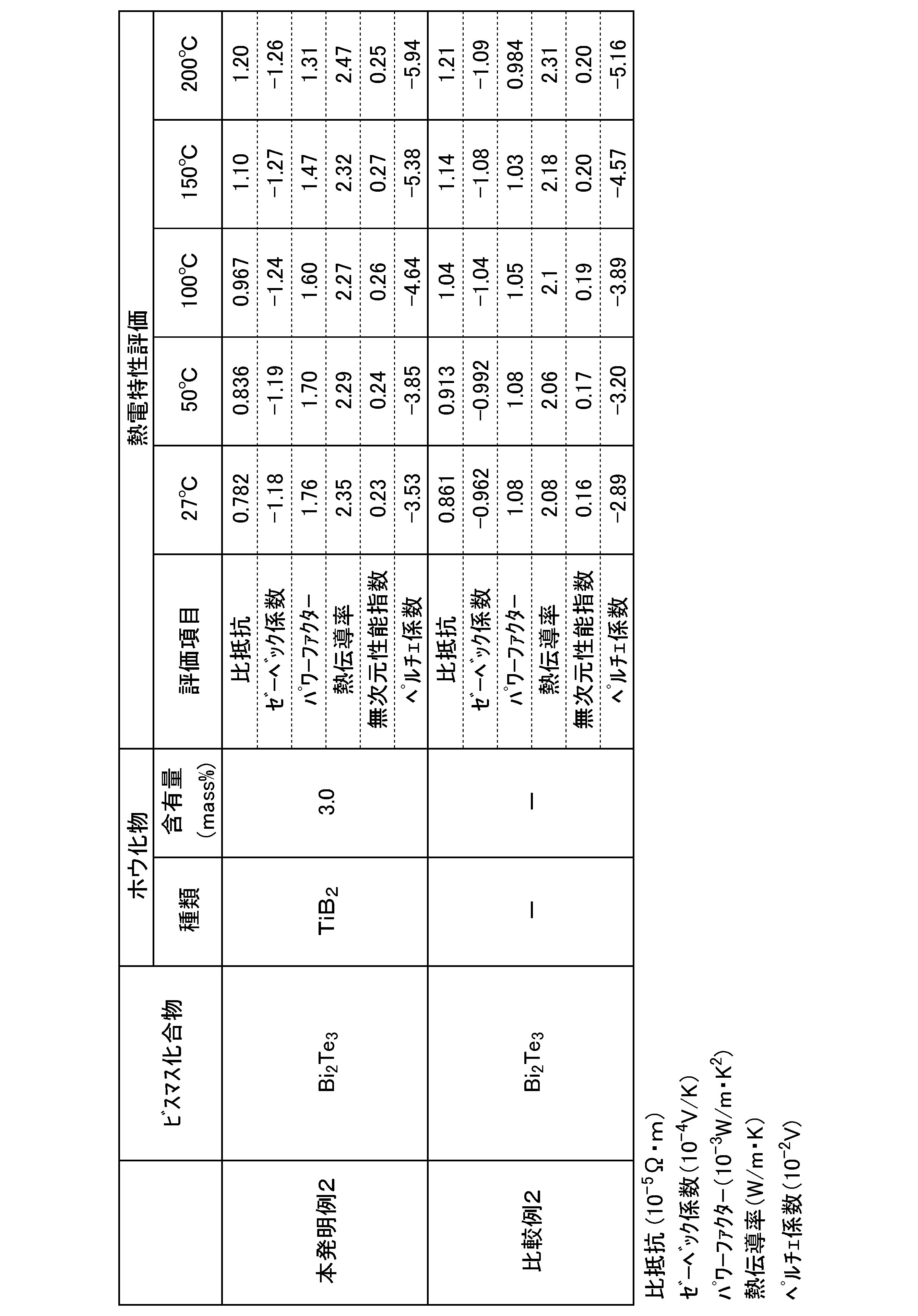
ホウ化物を添加した本発明例2においては、ホウ化物を添加しなかった比較例2に比べて、各種温度でゼーベック係数S、パワーファクターPF、ペルチェ係数の絶対値が高く、熱電特性(熱電変換効率)が優れていることが確認される。
(実施例3)
この実施例3では、実施例1で得られた本発明例1および比較例1の熱電変換材料(BixSb2―xTe3(0<x≦0.6))、実施例2で得られた本発明例2および比較例2の熱電変換材料(Bi2Te3―ySey(0≦y≦3))の強度について評価した。
上述の熱電変換材料に対して、温度27℃および200℃で、それぞれ3点曲げ試験を実施し、曲げ強さを測定した。測定結果を表3に示す。
この実施例3では、実施例1で得られた本発明例1および比較例1の熱電変換材料(BixSb2―xTe3(0<x≦0.6))、実施例2で得られた本発明例2および比較例2の熱電変換材料(Bi2Te3―ySey(0≦y≦3))の強度について評価した。
上述の熱電変換材料に対して、温度27℃および200℃で、それぞれ3点曲げ試験を実施し、曲げ強さを測定した。測定結果を表3に示す。
3点曲げ試験機は、島津オートグラフ(AG-25TD)を用いた。試験治具はSiC製3点曲げ治具で、支点間距離は12mmで行った。
試験雰囲気は、27℃では大気、200℃ではAr雰囲気で行った。クロスヘッドの変位速度は0.5mm/min、昇温速度は20℃/min、試験温度に到達後15分保持したのち、3点曲げ試験を実施した。曲げ強さは、破断時の最大荷重から以下の式を用いて、曲げ強さ(MPa)を求めた。
曲げ強さ(MPa)=3/2×Fmax×L/(t2×W)
Fmax:最大荷重(N)、L:支点間距離(mm)
t:試験片厚さ(mm)、W:試験片幅(mm)
試験雰囲気は、27℃では大気、200℃ではAr雰囲気で行った。クロスヘッドの変位速度は0.5mm/min、昇温速度は20℃/min、試験温度に到達後15分保持したのち、3点曲げ試験を実施した。曲げ強さは、破断時の最大荷重から以下の式を用いて、曲げ強さ(MPa)を求めた。
曲げ強さ(MPa)=3/2×Fmax×L/(t2×W)
Fmax:最大荷重(N)、L:支点間距離(mm)
t:試験片厚さ(mm)、W:試験片幅(mm)

BixSb2―xTe3(0<x≦0.6)にホウ化物を添加した本発明例1においては、比較例1に比べて、27℃および200℃のいずれの温度でも曲げ強度が向上した。
Bi2Te3―ySey(0≦y≦3)にホウ化物を添加した本発明例2においては、比較例2に比べて、27℃での曲げ強度が向上した。
Bi2Te3―ySey(0≦y≦3)にホウ化物を添加した本発明例2においては、比較例2に比べて、27℃での曲げ強度が向上した。
(実施例4)
この実施例4では、BixSb2―xTe3(x=0.3)を主成分とする熱電変換材料の熱電特性について評価した。
純度99.999mass%のBi粉(平均粒径2mm)、純度99.999mass%のSb粉(粒径2mm)、純度99.999mass%のTe粉(粒径2mm)を準備し、これらを秤量して石英容器入れて、酸化を防ぐために内部にArガスを封入し、700℃で5時間加熱した。これにより、表4に示す組成の塊状ビスマス化合物を得た。
次に、この塊状ビスマス化合物を乳鉢中で細かく砕いて、これを分級して平均粒径が100μmの塊状ビスマス化合物粉を得た。
この実施例4では、BixSb2―xTe3(x=0.3)を主成分とする熱電変換材料の熱電特性について評価した。
純度99.999mass%のBi粉(平均粒径2mm)、純度99.999mass%のSb粉(粒径2mm)、純度99.999mass%のTe粉(粒径2mm)を準備し、これらを秤量して石英容器入れて、酸化を防ぐために内部にArガスを封入し、700℃で5時間加熱した。これにより、表4に示す組成の塊状ビスマス化合物を得た。
次に、この塊状ビスマス化合物を乳鉢中で細かく砕いて、これを分級して平均粒径が100μmの塊状ビスマス化合物粉を得た。
そして、本発明例11,12では、表4に示すホウ化物粉(純度99.9mass%、平均粒径3μm)を準備する。これを表4に示す含有量となるように秤量し、塊状ビスマス化合物粉とホウ化物粉とを混合し、焼結原料粉を得た。
得られた焼結原料粉をカーボンシートで内側を覆ったカーボンモールドに充填した。そして、図3に示す焼結装置(通電焼結装置100)によって、焼結温度470~480℃、焼結温度での保持時間5分、加圧圧力30MPaの条件で通電焼結した。
得られた焼結原料粉をカーボンシートで内側を覆ったカーボンモールドに充填した。そして、図3に示す焼結装置(通電焼結装置100)によって、焼結温度470~480℃、焼結温度での保持時間5分、加圧圧力30MPaの条件で通電焼結した。
そして、得られた焼結体を、ダイヤモンドバンドソーを用いて所定のサイズに切断し、切断後の焼結体の表面を各種番手のサンドペーパーで研磨した。これにより、表1に示す組成の熱電変換材料を得た。
上述のようにして得られた熱電変換材料に対して、実施例1と同様に、各種温度における比抵抗R、ゼーベック係数S、パワーファクターPF、熱伝導率κ、無次元性能指数ZT、ペルチェ係数πについて評価した。評価結果を表4に示す。
上述のようにして得られた熱電変換材料に対して、実施例1と同様に、各種温度における比抵抗R、ゼーベック係数S、パワーファクターPF、熱伝導率κ、無次元性能指数ZT、ペルチェ係数πについて評価した。評価結果を表4に示す。
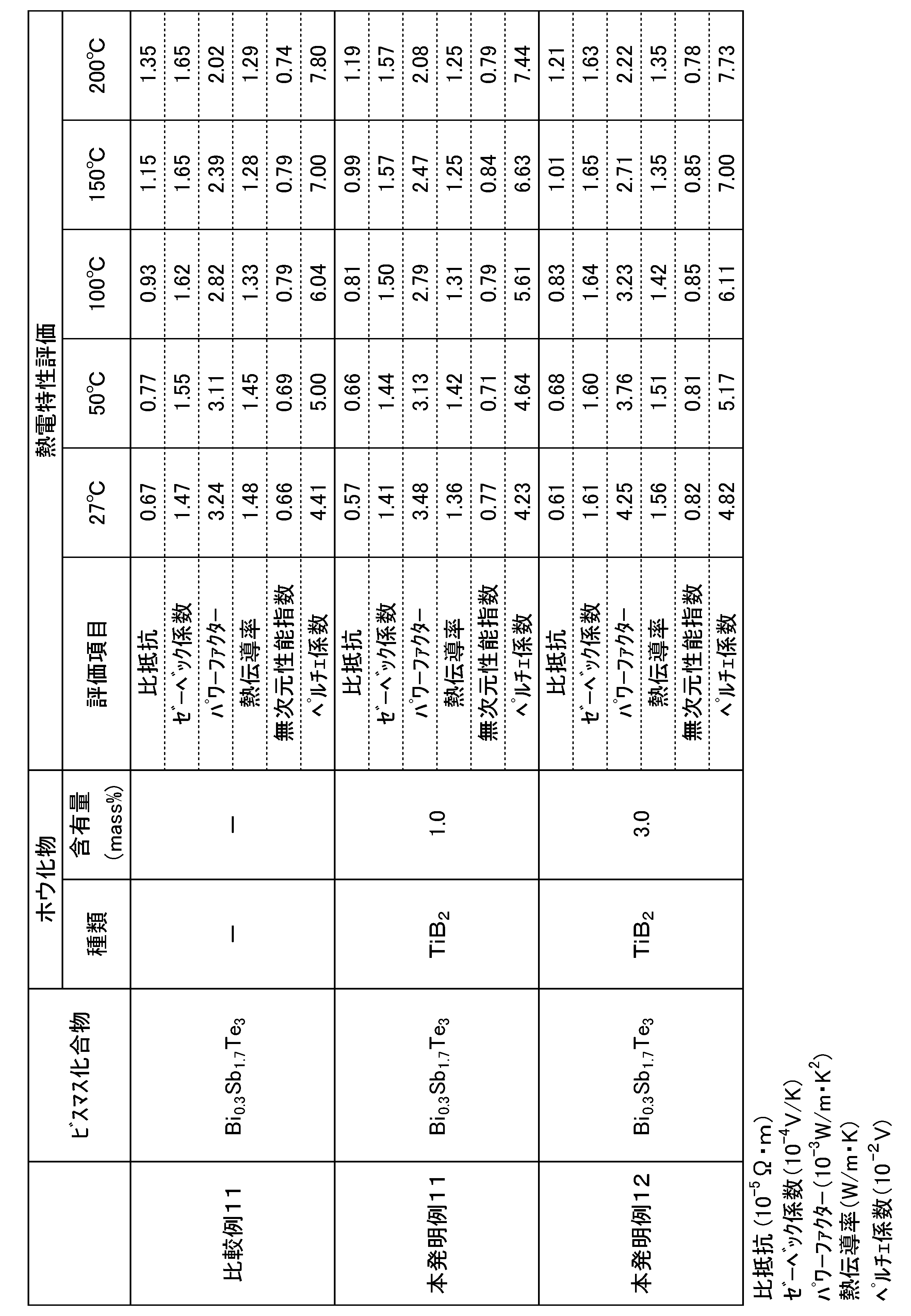
ホウ化物を添加した本発明例11,12においては、ホウ化物を添加しなかった比較例11に比べて、パワーファクターPF、無次元性能指数ZTが優れていることが確認される。
また、本発明例11,12を比較すると、ホウ化物の含有量が多くなると、パワーファクターPF、無次元性能指数ZTがさらに優れることが確認される。
さらに、実施例1の本発明例1に比べて、焼結温度を高く設定した本発明例11,12の方が、パワーファクターPF、無次元性能指数ZTが優れていることが確認される。
また、本発明例11,12を比較すると、ホウ化物の含有量が多くなると、パワーファクターPF、無次元性能指数ZTがさらに優れることが確認される。
さらに、実施例1の本発明例1に比べて、焼結温度を高く設定した本発明例11,12の方が、パワーファクターPF、無次元性能指数ZTが優れていることが確認される。
(実施例5)
この実施例5では、Bi2Te3―ySey(y=0)を主成分とする熱電変換材料の熱電特性について評価した。
純度99.999mass%のBi粉(平均粒径2mm)、純度99.999mass%のTe粉(粒径2mm)を準備し、これらを秤量して、石英容器入れて、酸化を防ぐために内部にArガスを封入し、700℃で5時間加熱した。これにより、表5に示す組成の塊状ビスマス化合物を得た。
次に、この塊状ビスマス化合物を乳鉢中で細かく砕いて、これを分級して平均粒径が100μmの塊状ビスマス化合物粉を得た。
この実施例5では、Bi2Te3―ySey(y=0)を主成分とする熱電変換材料の熱電特性について評価した。
純度99.999mass%のBi粉(平均粒径2mm)、純度99.999mass%のTe粉(粒径2mm)を準備し、これらを秤量して、石英容器入れて、酸化を防ぐために内部にArガスを封入し、700℃で5時間加熱した。これにより、表5に示す組成の塊状ビスマス化合物を得た。
次に、この塊状ビスマス化合物を乳鉢中で細かく砕いて、これを分級して平均粒径が100μmの塊状ビスマス化合物粉を得た。
そして、本発明例21,22では、表5に示すホウ化物粉(純度99.9mass%、平均粒径3μm)を準備する。これを表5に示す含有量となるように秤量し、塊状ビスマス化合物粉とホウ化物粉とを混合し、焼結原料粉を得た。
得られた焼結原料粉をカーボンシートで内側を覆ったカーボンモールドに充填した。そして、図3に示す焼結装置(通電焼結装置100)によって、焼結温度500~520℃、焼結温度での保持時間5分、加圧圧力30MPaの条件で通電焼結した。
得られた焼結原料粉をカーボンシートで内側を覆ったカーボンモールドに充填した。そして、図3に示す焼結装置(通電焼結装置100)によって、焼結温度500~520℃、焼結温度での保持時間5分、加圧圧力30MPaの条件で通電焼結した。
そして、得られた焼結体を、ダイヤモンドバンドソーを用いて所定のサイズに切断し、切断後の焼結体の表面を各種番手のサンドペーパーで研磨した。これにより、表5に示す組成の熱電変換材料を得た。
上述のようにして得られた熱電変換材料に対して、実施例1と同様に、各種温度における比抵抗R、ゼーベック係数S、パワーファクターPF、熱伝導率κ、無次元性能指数ZT、ペルチェ係数πについて評価した。また、比較例21および本発明例21については、-73℃,-43℃,-1℃の0℃以下の温度における比抵抗R、ゼーベック係数S、パワーファクターPF、ペルチェ係数πについて評価した。なお、0℃以下の熱電特性の評価は、アドバンス理工製ZEM-3の加熱炉をクライオスタットに交換して測定した。評価結果を表5に示す。
上述のようにして得られた熱電変換材料に対して、実施例1と同様に、各種温度における比抵抗R、ゼーベック係数S、パワーファクターPF、熱伝導率κ、無次元性能指数ZT、ペルチェ係数πについて評価した。また、比較例21および本発明例21については、-73℃,-43℃,-1℃の0℃以下の温度における比抵抗R、ゼーベック係数S、パワーファクターPF、ペルチェ係数πについて評価した。なお、0℃以下の熱電特性の評価は、アドバンス理工製ZEM-3の加熱炉をクライオスタットに交換して測定した。評価結果を表5に示す。

ホウ化物を添加した本発明例21,22においては、ホウ化物を添加しなかった比較例21に比べて、ゼーベック係数S、ペルチェ係数πが優れていることが確認される。
また、本発明例21,22を比較すると、ホウ化物の含有量が多くなると、ゼーベック係数S、ペルチェ係数πがさらに優れることが確認される。
さらに、実施例2の本発明例2に比べて、焼結温度を高く設定した本発明例21,22の方が、ゼーベック係数S、ペルチェ係数πが優れていることが確認される。
特に、ホウ化物を含有する本発明例21では、-73℃から50℃の比較的低温の範囲において、ゼーベック係数S、ペルチェ係数π以外に、パワーファクターPFも優れていることが確認される。
また、本発明例21,22を比較すると、ホウ化物の含有量が多くなると、ゼーベック係数S、ペルチェ係数πがさらに優れることが確認される。
さらに、実施例2の本発明例2に比べて、焼結温度を高く設定した本発明例21,22の方が、ゼーベック係数S、ペルチェ係数πが優れていることが確認される。
特に、ホウ化物を含有する本発明例21では、-73℃から50℃の比較的低温の範囲において、ゼーベック係数S、ペルチェ係数π以外に、パワーファクターPFも優れていることが確認される。
(実施例6)
この実施例6では、実施例4で得られた本発明例12,本発明例12のホウ化物の添加量を5mass%に変更した本発明例13および比較例11の熱電変換材料(BixSb2―xTe3(x=0.3))の強度について評価した。
上述の熱電変換材料に対して、実施例3と同様に、温度27℃および200℃で、それぞれ3点曲げ試験を実施し、曲げ強さを測定した。測定結果を表6に示す。
この実施例6では、実施例4で得られた本発明例12,本発明例12のホウ化物の添加量を5mass%に変更した本発明例13および比較例11の熱電変換材料(BixSb2―xTe3(x=0.3))の強度について評価した。
上述の熱電変換材料に対して、実施例3と同様に、温度27℃および200℃で、それぞれ3点曲げ試験を実施し、曲げ強さを測定した。測定結果を表6に示す。
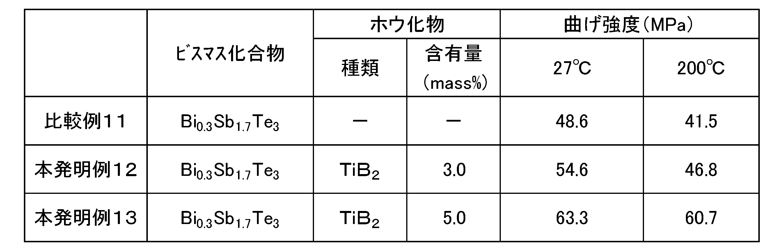
本発明例12,13および比較例11を比較すると、温度27℃および200℃において、ホウ化物の含有量が多くなると、強度が向上することが確認された。
以上のことから、本発明例によれば、熱電特性、強度に優れた熱電変換材料、および、この熱電変換材料を用いた熱電変換素子、ペルチェ素子、および、熱電変換モジュール、ペルチェモジュールを提供可能であることが確認された。
1 熱電変換モジュール(ペルチェモジュール)
10 熱電変換素子(ペルチェ素子)
11 熱電変換材料
18a,18b 電極
19a,19b 金属板
10 熱電変換素子(ペルチェ素子)
11 熱電変換材料
18a,18b 電極
19a,19b 金属板
Claims (10)
- テルルおよびアンチモン、あるいは、テルルおよびセレンの少なくとも一方とビスマスとを含むビスマス化合物と、
チタン、ジルコニウム、ハフニウムから選択される少なくとも一種の金属を含むホウ化物と、を含有することを特徴とする熱電変換材料。 - 前記ビスマス化合物は、BixSb2―xTe3(0<x≦0.6)であることを特徴とする請求項1に記載の熱電変換材料。
- 前記ビスマス化合物は、Bi2Te3―ySey(0≦y≦3)であることを特徴とする請求項1に記載の熱電変換材料。
- 前記ホウ化物が、TiB2,ZrB2,HfB2から選択される一種又は二種以上であることを特徴とする請求項1から請求項3のいずれか一項に記載の熱電変換材料。
- 前記熱電変換材料に対する前記ビスマス化合物の質量割合が、50mass%以上99.5mass%以下の範囲内とされていることを特徴とする請求項1から請求項4のいずれか一項に記載の熱電変換材料。
- 前記熱電変換材料に対する前記ホウ化物の合計含有量が0.5mass%以上15mass%以下の範囲内とされていることを特徴とする請求項1から請求項5のいずれか一項に記載の熱電変換材料。
- 請求項1から請求項6のいずれか一項に記載の熱電変換材料と、前記熱電変換材料の一方の面および対向する他方の面にそれぞれ接合された電極と、を備えたことを特徴とする熱電変換素子。
- 請求項1から請求項6のいずれか一項に記載の熱電変換材料と、前記熱電変換材料の一方の面および対向する他方の面にそれぞれ接合された電極と、を備えたことを特徴とするペルチェ素子。
- 請求項7に記載の熱電変換素子と、前記熱電変換素子の前記電極にそれぞれ接合された金属板と、を備えたことを特徴とする熱電変換モジュール。
- 請求項8に記載のペルチェ素子と、前記ペルチェ素子の前記電極にそれぞれ接合された金属板と、を備えたことを特徴とするペルチェモジュール。
Applications Claiming Priority (4)
| Application Number | Priority Date | Filing Date | Title |
|---|---|---|---|
| JP2020155147 | 2020-09-16 | ||
| JP2020-155147 | 2020-09-16 | ||
| JP2021-134026 | 2021-08-19 | ||
| JP2021134026A JP2022049670A (ja) | 2020-09-16 | 2021-08-19 | 熱電変換材料、熱電変換素子、ペルチェ素子、および、熱電変換モジュール、ペルチェモジュール |
Publications (1)
| Publication Number | Publication Date |
|---|---|
| WO2022059593A1 true WO2022059593A1 (ja) | 2022-03-24 |
Family
ID=80776990
Family Applications (1)
| Application Number | Title | Priority Date | Filing Date |
|---|---|---|---|
| PCT/JP2021/033163 Ceased WO2022059593A1 (ja) | 2020-09-16 | 2021-09-09 | 熱電変換材料、熱電変換素子、ペルチェ素子、および、熱電変換モジュール、ペルチェモジュール |
Country Status (2)
| Country | Link |
|---|---|
| TW (1) | TW202225422A (ja) |
| WO (1) | WO2022059593A1 (ja) |
Citations (2)
| Publication number | Priority date | Publication date | Assignee | Title |
|---|---|---|---|---|
| JP2001274464A (ja) * | 2000-03-23 | 2001-10-05 | Asahi Glass Co Ltd | n型熱電変換材料およびその製造方法 |
| JP2004349566A (ja) * | 2003-05-23 | 2004-12-09 | Kyocera Corp | 一方向凝固熱電結晶材料とその製造方法、これを用いた熱電素子とその製造方法、及び熱電モジュール |
-
2021
- 2021-09-09 WO PCT/JP2021/033163 patent/WO2022059593A1/ja not_active Ceased
- 2021-09-13 TW TW110133981A patent/TW202225422A/zh unknown
Patent Citations (2)
| Publication number | Priority date | Publication date | Assignee | Title |
|---|---|---|---|---|
| JP2001274464A (ja) * | 2000-03-23 | 2001-10-05 | Asahi Glass Co Ltd | n型熱電変換材料およびその製造方法 |
| JP2004349566A (ja) * | 2003-05-23 | 2004-12-09 | Kyocera Corp | 一方向凝固熱電結晶材料とその製造方法、これを用いた熱電素子とその製造方法、及び熱電モジュール |
Also Published As
| Publication number | Publication date |
|---|---|
| TW202225422A (zh) | 2022-07-01 |
Similar Documents
| Publication | Publication Date | Title |
|---|---|---|
| JP7251187B2 (ja) | 熱電変換材料、熱電変換素子、熱電変換モジュール、及び、熱電変換材料の製造方法 | |
| WO2014084163A1 (ja) | Mg-Si系熱電変換材料及びその製造方法、熱電変換用焼結体、熱電変換素子、並びに熱電変換モジュール | |
| CN108780833A (zh) | 镁系热电转换材料、镁系热电转换元件、热电转换装置、镁系热电转换材料的制造方法 | |
| KR102299167B1 (ko) | 마그네슘계 열전 변환 재료, 마그네슘계 열전 변환 소자, 열전 변환 장치, 마그네슘계 열전 변환 재료의 제조 방법 | |
| KR102409289B1 (ko) | 마그네슘계 열전 변환 재료, 마그네슘계 열전 변환 소자, 및 마그네슘계 열전 변환 재료의 제조 방법 | |
| JP7291461B2 (ja) | 熱電変換材料、熱電変換素子、及び、熱電変換モジュール | |
| JP7121227B2 (ja) | 熱電変換材料、及び、熱電変換材料の製造方法 | |
| CN111630672A (zh) | 热电转换元件 | |
| WO2022059593A1 (ja) | 熱電変換材料、熱電変換素子、ペルチェ素子、および、熱電変換モジュール、ペルチェモジュール | |
| JP2022049670A (ja) | 熱電変換材料、熱電変換素子、ペルチェ素子、および、熱電変換モジュール、ペルチェモジュール | |
| WO2021187225A1 (ja) | 熱電変換材料、熱電変換素子、及び、熱電変換モジュール | |
| JP7631702B2 (ja) | 熱電変換材料、熱電変換素子、および、熱電変換モジュール | |
| KR20220115801A (ko) | 열전 변환 재료, 열전 변환 소자, 및, 열전 변환 모듈 | |
| WO2019168029A1 (ja) | 熱電変換材料、熱電変換素子、熱電変換モジュール、及び、熱電変換材料の製造方法 | |
| JP7248157B2 (ja) | 熱電変換材料、及び、熱電変換材料の製造方法 | |
| Prasad et al. | Development of PbTe material for advanced thermoelectric power generation | |
| JP2018157130A (ja) | 熱電変換材料の製造方法 | |
| WO2019177147A1 (ja) | 熱電変換素子 |
Legal Events
| Date | Code | Title | Description |
|---|---|---|---|
| 121 | Ep: the epo has been informed by wipo that ep was designated in this application |
Ref document number: 21869280 Country of ref document: EP Kind code of ref document: A1 |
|
| NENP | Non-entry into the national phase |
Ref country code: DE |
|
| 122 | Ep: pct application non-entry in european phase |
Ref document number: 21869280 Country of ref document: EP Kind code of ref document: A1 |