WO2022054815A1 - 処理風発生装置 - Google Patents
処理風発生装置 Download PDFInfo
- Publication number
- WO2022054815A1 WO2022054815A1 PCT/JP2021/032929 JP2021032929W WO2022054815A1 WO 2022054815 A1 WO2022054815 A1 WO 2022054815A1 JP 2021032929 W JP2021032929 W JP 2021032929W WO 2022054815 A1 WO2022054815 A1 WO 2022054815A1
- Authority
- WO
- WIPO (PCT)
- Prior art keywords
- air
- outlet
- processing
- ion generator
- wind generator
- Prior art date
- Legal status (The legal status is an assumption and is not a legal conclusion. Google has not performed a legal analysis and makes no representation as to the accuracy of the status listed.)
- Ceased
Links
Images






Classifications
-
- A—HUMAN NECESSITIES
- A41—WEARING APPAREL
- A41G—ARTIFICIAL FLOWERS; WIGS; MASKS; FEATHERS
- A41G3/00—Wigs
-
- A—HUMAN NECESSITIES
- A61—MEDICAL OR VETERINARY SCIENCE; HYGIENE
- A61L—METHODS OR APPARATUS FOR STERILISING MATERIALS OR OBJECTS IN GENERAL; DISINFECTION, STERILISATION OR DEODORISATION OF AIR; CHEMICAL ASPECTS OF BANDAGES, DRESSINGS, ABSORBENT PADS OR SURGICAL ARTICLES; MATERIALS FOR BANDAGES, DRESSINGS, ABSORBENT PADS OR SURGICAL ARTICLES
- A61L2/00—Disinfection or sterilisation of materials or objects, in general; Accessories therefor
- A61L2/02—Disinfection or sterilisation of materials or objects, in general; Accessories therefor using physical processes
- A61L2/14—Plasma, i.e. ionised gases
-
- F—MECHANICAL ENGINEERING; LIGHTING; HEATING; WEAPONS; BLASTING
- F24—HEATING; RANGES; VENTILATING
- F24F—AIR-CONDITIONING; AIR-HUMIDIFICATION; VENTILATION; USE OF AIR CURRENTS FOR SCREENING
- F24F8/00—Treatment, e.g. purification, of air supplied to human living or working spaces otherwise than by heating, cooling, humidifying or drying
- F24F8/80—Self-contained air purifiers
Definitions
- the present invention relates to a processing air generator that sends out processing air having a deodorizing effect.
- a deodorizing / sterilizing device for a wig or the like As a device for removing odors and bacteria adhering to a wig or the like, a deodorizing / sterilizing device for a wig or the like according to Patent Document 1 is known.
- the deodorizing / sterilizing device for wigs and the like described in Patent Document 1 includes a mounting table on which an object for deodorizing and sterilizing such as a wig is placed, an ozone generating means for generating ozone from oxygen in the air, and an ozone generating means. Equipped with a blower fan.
- the mounting table is hemispherically formed and has an outlet.
- the ozone generated by the ozone generating means is included in the air flow (hereinafter referred to as wind) by the blower fan and blown out from the outlet of the mounting table.
- the ozone generating means is provided inside the mounting table, and the blower fan is provided inside the pedestal portion. Therefore, the wind containing ozone cannot be applied to any part of the object, and it cannot be said that it is easy to use.
- One aspect of the present invention is to realize an easy-to-use treatment air generator capable of deodorizing by applying treatment air to an arbitrary part of an object.
- the processing air generator is a processing air generator that sends out processing air that is air containing particles, and has a blower unit that sucks air from a suction port.
- the air passage that guides the air sucked by the air blower to the air outlet, the discharge part that is arranged facing the air passage and generates particles by electric discharge, and the air outlet in the processing air generator.
- an easy-to-use treatment air generator capable of deodorizing by applying treatment air to an arbitrary part of an object.
- FIG. D1 of FIG. It is sectional drawing of the cut surface D1 of FIG. It is sectional drawing of the cut surface D2 of FIG. It is an enlarged view of the area A1 of FIG.
- FIG. D2 of FIG. It is a perspective view of the wig storage apparatus on which the ion generator which concerns on this embodiment is mounted.
- An example is shown in which the ion generator is installed in the first installation portion of the stand portion using the outer shape of the lower part. It is a figure which shows the example which the ion generator is installed in the 2nd installation part of the stand part by using the hook. It is a figure which shows the example which the ion generator is installed in the 3rd installation part of the stand part by using the hook. It is a figure which shows the example which holds and uses the ion generator removed from the stand part by hand.
- a processing wind generator mounted on a wig storage device capable of deodorizing and storing a wig (wig) which is a symmetrical object
- a processing air generator an ion generator that sends out ion air as a processing air having deodorizing, sterilizing, and static elimination effects to an object is exemplified.
- FIG. 5 is a perspective view of the wig storage device 100 on which the ion generator according to the present embodiment is mounted. As shown in FIG. 5, the wig storage device 100 includes an ion generator 2 and a stand portion 3 as processing wind generators.
- the ion generator 2 generates ions by electric discharge and sends out ion air as a processing air.
- the generated ions include positive (+) ions (eg, H + (H 2 O) m (m is any natural number)) or negative (-) ions (eg, O 2- (H 2 O) n (n). May be any natural number)))) or both.
- the wig is easily damaged if stored in a charged state. Therefore, when the object is a wig, the ion generator 2 that sends out an ion wind that can remove static electricity in addition to deodorizing is effective, and deterioration of the wig can be suppressed by performing static elimination. Further, regardless of the wig, it is preferable to be able to perform sterilization in addition to deodorizing, and the ion generator 2 that sends out an ion wind capable of sterilizing is effective.
- the stand portion 3 holds the wig 4 and allows the ion generator 2 to be detachably installed.
- the stand portion 3 can install the ion generator 2 at a plurality of locations where the parts of the wig 4 to which the ion wind sent from the ion generator 2 hits are different from each other.
- the stand portion 3 has a wig holding portion 15, an arm portion 16, a leg portion 17, a hanging portion 18, and a plurality of installation portions 19.
- the wig holding portion 15 holds the wig 4 (see FIG. 6) from the inside.
- the wig holding portion 15 has a first frame 15a and a second frame 15b, each of which is formed in an elliptical shape. The four curved frame portions formed by combining the first frame 15a and the second frame 15b partially contact the inner surface of the wig 4 to hold the wig 4 from the inside.
- the arm portion 16 extends upward of the wig holding portion 15, and its upper end portion is at a position higher than that of the wig holding portion 15.
- the arm portion 16 secures a space above the wig holding portion 15 and enables the ion generator 2 to be installed above the wig holding portion 15.
- the arm portion 16 is formed in an arc shape curved toward the outside.
- the leg portion 17 is provided at the lower part of the stand portion 3 and enables the stand portion 3 to stand on its own. By providing the legs 17, the wig storage device 100 can be used in a state of being placed on a desk or the like. In the example of FIG. 5, the leg portion 17 has four legs 17a.
- the hanging portion 18 is a hook-shaped member provided upward on the upper part of the stand portion 3 so that the stand portion 3 can be suspended.
- the wig storage device 100 can be used in a state of being suspended from a bar or the like of a closet (see FIG. 8).
- the hanging portion 18 is provided at the upper end portion of the arm portion 16.
- the hanging portion 18 is preferably provided so that the open portion 18a faces the arm portion 16 side.
- the wig storage device 100 can be easily suspended so that the arm portion 16 side is located on the back side of the closet and the wig holding portion 15 side is located on the front side of the closet with respect to the bar or the like of the closet. Can be done (see FIG. 8).
- the wig 4 is placed on the wig holding portion 15 and is placed (held) on the wig holding portion 15.
- the existing wig 4 can be easily taken out.
- the installation unit 19 allows the ion generator 2 to be detachably installed on the stand unit 3.
- the installation unit 19 is provided at a plurality of locations on the stand unit so that the ion generator 2 can be installed at a plurality of locations on the stand unit 3.
- the ion wind sent from the ion generator 2 installed in each installation unit 19 hits different parts of the wig 4.
- the installation unit 19 is provided at three locations as the first installation unit 19A to the third installation unit 19C.
- the first installation unit 19A is provided at the lower part of the wig holding unit 15, and the ion generator 2 is installed at the lower part of the wig holding unit 15 with the wind direction facing upward. More specifically, the first installation portion 19A is composed of a recess 23 formed in the central portion of the four legs 17a of the leg portion 17. The inner shape of the recess 23 corresponds to the outer shape (corresponding to the first locking portion) of the lower part of the case 10 described later of the ion generator 2, and the ion generator 2 can be stably held. ..
- a recess is formed in a portion where the first frame 15a and the second frame 15b, which are the bottom of the recess 23, intersect.
- the hook 6 of the ion generator 2 is adapted to fit in this recess in the state of being installed in the first installation portion 19A.
- the second installation portion 19B is provided at the upper end portion of the arm portion 16, and the ion generator 2 is installed at the upper end portion of the arm portion 16 with the wind direction facing downward. More specifically, the second installation portion 19B is composed of a hook 24 formed downward on the upper end portion of the arm portion 16. By hooking the hook 6 of the ion generator 2 to the hook 24, the ion generator 2 can be held in a suspended state.
- the hook 24 is provided so that the open portion 24a faces the side opposite to the arm portion 16. In the configuration in which the opening portion 24a faces the arm portion 16 side, it is necessary to temporarily dive the ion generator 2 under the hook 24 and then lift and hook the ion generator 2. However, by directing the open portion 24a to the side opposite to the arm portion 16, the ion generator 2 can be easily hooked without diving under the hook 24.
- the arm portion 16 is provided with a hook 21 that can be used to hook the power cable 11 of the ion generator 2 installed in the second installation portion 19B.
- the third installation unit 19C is provided inside the upper part of the wig holding part 15, and the ion generator 2 is installed inside the upper part of the wig holding part 15 with the wind direction facing downward. More specifically, the third installation portion 19C is composed of a hook 25 formed on the second frame 15b of the wig holding portion 15. By hooking the hook 6 of the ion generator 2 to the hook 25, the ion generator 2 can be held in a suspended state.
- the hook 25 is provided so that the open portion 25a faces the side opposite to the arm portion 16.
- the second frame 15b is provided with a hook 22 that can be used to hook the power cable 11 of the ion generator 2 installed in the third installation unit 19C.
- FIG. 1 is a perspective view of the ion generator 2 according to the present embodiment.
- FIG. 2 is a schematic cross-sectional view of the cut surface D1 of FIG.
- FIG. 3 is a schematic cross-sectional view of the cut surface D2 of FIG.
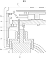
- FIG. 4 is an enlarged view of the region A1 of FIG.
- the ion generator 2 has a bell-shaped case 10, and an outlet 5 is provided on the circular surface of the case 10 which is the mouth side of the bell-shaped case 10.
- a hook 6 (locking portion, second locking portion) for suspending and installing the ion generator 2 is provided on the curved surface of the case 10 on the opposite side of the air outlet 5.
- the side where the outlet 5 is provided will be referred to as "upper”
- the curved surface side where the hook 6 is provided will be referred to as "lower”.
- a suction port 7 is formed on the side wall connecting the side of the case 10 where the outlet 5 is located and the side of the case 10 where the hook 6 is located.
- the suction port 7 is provided in the lower part of the side wall of the case 10. As shown in FIG. 3, the lower side wall of the case 10 has a constricted shape in which two opposing surfaces approach each other.
- the suction port 7 is provided so as to face both sides of this narrowed portion.
- the inside of the case 10 is provided with a discharge device (discharge section) 8, a blower fan (blower section) 9, an air passage 12, and the like.
- the discharge device 8 generates particles (at least particles that deodorize) by electric discharge. In this embodiment, ions that deodorize, sterilize, and eliminate static electricity are generated.
- the blower fan 9 sucks air from the suction port 7, and the air passage 12 guides the sucked air to the outlet 5.
- the air passage 12 is formed so as to connect the suction port 7 and the air outlet 5, and the blower fan 9 is arranged in the air passage 12.
- the discharge device 8 is arranged facing the air passage 12, and a discharge portion 8a for discharging ions is located in the air passage 12.
- the discharge unit 8a of the discharge device 8 includes two brush electrodes 8b as electrodes. Positive ions are generated by electric discharge from one brush electrode 8b, and negative ions are generated by electric discharge from the other brush electrode 8b.
- the air sent out to the air passage 12 contains the ions released from the discharge device 8 to become an ion wind, and is blown out from the outlet 5.
- the hook 6 described above is for suspending and installing the ion generator 2, and is a locking portion for detachably installing the ion generator 2 on the stand portion 3.
- the hook 6 is a rotary hook that rotatably supports the ion generator 2 (case 10), and is rotatable in a suspended state.
- the ion generator 2 has an outer shape (first locking portion) 10e of the lower portion of the case 10 as a locking portion separate from the hook 6.
- the outer shape 10e corresponds to the inner shape of the recess 23 (see FIG. 5) constituting the first installation portion 19A in the stand portion 3 described above.
- the blower fan 9 is arranged on the lower side, which is the end side opposite to the outlet 5, so that the center of gravity of the ion generator 2 is located on the lower side.
- an operation unit 20 for receiving an operation such as turning on / off the ion generator 2 is also provided on the upper surface of the ion generator 2 in which the outlet 5 is formed.
- the outlet 5 is located on one side of the upper surface of the ion generator 2 in the radial direction (positions biased to one side on the upper surface or located on one side from the center of the upper surface), and the operation unit 20 is provided on the other side. Has been done.
- the operation unit 20 and the like can be arranged on the other side, and the product size can be reduced.
- a recess 10a recessed inward in the radial direction is formed in the upper part of the side wall of the case 10 located below the operation unit 20.
- a protruding portion 10b protruding outward in the radial direction is formed below the operating portion 20.
- a circuit board 13 for driving the discharge device 8 and the blower fan 9 is disposed inside the projecting portion 10b and on the lower surface side of the operation unit 20.
- a connection portion 30 for connecting the power cable 11 is provided on the lower surface 10c of the protruding portion 10b (the surface of the recess 10a facing the opposite side of the outlet 5).
- connection portion 30 includes a board-side connection terminal (connection portion) 31 connected to the circuit board 13.
- the board-side connection terminal 31 is located inside the opening 10d formed on the lower surface 10c of the protruding portion 10b.
- the cable-side connection terminal 32 provided at one end of the power cable 11 is inserted into the connection portion 30 from the lower side of the protruding portion 10b via the opening 10d provided on the lower surface 10c, and is inserted into the substrate-side connection terminal 31. Be connected.
- the direction in which the power cable 11 is connected is directed from the opposite side (lower side) of the outlet 5 to the outlet 5. It can be in the direction toward (the direction toward the upper side).
- the connection portion of the power cable 11 does not protrude toward the outside of the case 10, and the product size can be reduced.
- the concave portion 10a has a smooth curved surface on the opposite side (lower side) of the outlet 5, the cable side connection terminal 32 is smoothly opened at the opening 10d as compared with the case where the lower side is a vertical surface. Can be plugged into.
- the air passage 12 is located on one side in a side view, and a recess 10a is formed on the other side.
- the air passage 12 is arranged on one side to create an empty space on the other side, and the recess 10a is provided by utilizing this empty space. This optimizes the component layout, which also allows the product size to be reduced.
- the sirocco fan is used as the blower fan 9
- the air passage 12 can be easily arranged on one side and the product size can be reduced.
- the opening 10d is provided with a rib 34 as a reinforcing structure surrounding the substrate-side connection terminal 31.
- the rib 34 may be integrally formed with the case 10, or may be formed by fitting another component into the opening 10d.
- a dedicated AC adapter (not shown) is provided at the other end of the power cable 11, and AC (alternating current) power is converted to DC (direct current) and supplied to the circuit board.
- a USB terminal (not shown) may be provided at the other end of the power cable 11 so that the USB terminal and the AC adapter can be connected to each other.
- a groove 29 for fitting the power cable 11 is formed on the outer surface of the case 10.
- the groove 29 extends from the outlet 5 side toward the opposite side.
- the connection portion 30 is provided on the side with the outlet 5
- the power cable 11 extends from the side with the outlet 5, which may be an obstacle when the ion generator 2 is held and used.
- the groove 29 by forming the groove 29 on the outer surface of the case 10 and fitting the power cable 11 into the groove 29 in this way, the end side (lower side) opposite to the side with the outlet 5 (upper side). It is possible to obtain a feeling of use comparable to the structure in which the power cable 11 extends from.
- the end of the groove 29 is exposed in the recess 10a, the power cable 11 can be fitted directly into the groove 29 from the recess 10a.
- the ion generator 2 may be provided with a lid portion 35 for closing the recess 10a and / or the groove portion 29.
- a lid portion 35 for closing the recess 10a with the lid portion 35.
- the power cable 11 can be reliably fitted into the groove portion 29.
- ribs may be provided on the inner side of the lid portion 35 (on the groove portion 29 side) so as to face the groove portion 29. By providing the rib, the power cable 11 can be pushed into the groove 29 by the rib.
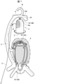
- FIG. 6 shows an example in which the ion generator 2 is installed in the first installation portion 19A of the stand portion 3 by using the outer shape 10e at the lower part.
- FIG. 6 shows an example in which the ion generator 2 is installed in the first installation portion 19A of the stand portion 3 by using the outer shape 10e at the lower part.
- FIG. 6 by installing and using the outlet 5 at the lower part of the stand portion 3 with the outlet 5 facing upward, it is possible to apply ion wind to the inner surface of the wig 4 held by the wig holding portion 15. can.
- the inner surface (the surface on the scalp side) of the wig 4 can be effectively deodorized, sterilized, and statically eliminated.
- the scalp odor adhering to the inside of the wig 4 can be effectively deodorized.
- FIG. 7 shows an example in which the ion generator 2 is installed in the second installation portion 19B of the stand portion 3 by using the hook 6.
- the ion generator 2 is installed in the second installation portion 19B of the stand portion 3 by using the hook 6.
- the ion generator 2 by installing the ion generator 2 on the upper part of the stand portion 3 with the outlet 5 facing downward, the ion wind is applied to the outer surface of the wig 4 held by the wig holding portion 15. Can be guessed.
- the outside of the wig 4 can be effectively deodorized, sterilized, and statically eliminated.
- the odor of cigarettes adhering to the outside of the wig 4 can be effectively deodorized.
- FIG. 8 shows an example in which the ion generator 2 is installed in the third installation portion 19C of the stand portion 3 by using the hook 6.
- the stand portion 3 is suspended by using the hanging portion 18.
- the ion generator 2 is directed toward the hair tips of the wig 4 held by the wig holding portion 15. You can hit the ion wind.
- the stand portion 3 in a suspended state, even the wig 4 for long hair can be exposed to the ion wind even to the tips of the hair.
- ions can be effectively distributed to the tips of the hair to deodorize, sterilize, and eliminate static electricity.
- the hook 6 of the ion generator 2 is a rotary hook
- the direction of the outlet 5 is manually oriented when the hook 6 is used while being suspended from the stand portion 3 as shown in FIGS. 7 and 8. It will be possible to change. This makes it possible to change the convection region of the ions.
- a louver may be provided at the outlet 5 of the ion generator 2 so that the ion wind is blown out diagonally with respect to the normal direction of the surface on which the outlet 5 is formed. With such a configuration, the ion generator 2 can be rotated by the wind force of the ion wind blown from one side, and the convection area of the ions can be further expanded.
- FIG. 9 shows an example in which the ion generator 2 removed from the stand portion 3 is held and used by hand. As shown in FIG. 9, it may be carried and used by the ion generator 2. This makes it possible to intensively deodorize and eliminate static electricity at any part of the wig 4. Further, brushing may be performed while applying an ion wind to the wig 4 held by the wig holding portion 15 (while emitting an ion wind toward the wig 4).
- the ion generator 2 may be provided with a louver structure in which the ion generator 5 is obliquely sent out to the outlet 5 with respect to the normal direction of the surface having the outlet.
- the louver structure in the outlet 5 By providing the louver structure in the outlet 5, the ion generator 2 can be rotated by the air (ion wind) blown from the outlet 5.
- an outlet for blowing air for rotating the ion generator 2 may be separately provided on the side wall (outer peripheral surface of the housing) of the case 10 of the ion generator 2. Even with such a configuration, the ion generator 2 can be rotated by the wind generated by the blower fan 9.
- a drive unit for rotating the ion generator 2 by a motor may be provided in the vicinity of the hook 6 without using wind.
- the ion generator 2 is exemplified as the processing air generator, but the processing air generator is a particle such as ions, electrons, ozone, radicals, active species, and charged particles (charged particles) due to electric discharge. Any discharge device may be used.
- an ion which is an example of a charged particle, is generated, it may be configured to generate both positive ions and negative ions, or it may be configured to generate either positive ions or negative ions.
- a rotatable hook 6 and an outer shape 10e at the bottom of the case 10 are exemplified as a locking portion for detachably installing the ion generator 2 on the stand portion 3.
- the locking portion is not limited to these, and any locking portion may be used as long as the ion generator 2 is detachably installed on the stand portion 3, for example, locking using a non-rotating hook or a hook-and-loop fastener. You may.
- the configuration mounted on the wig storage device 100 that holds and stores the wig (wig) is illustrated, but the object to be treated by the ion wind is not limited to the wig.
- it can be mounted on a device for holding and storing a hat, a helmet, shoes, boots, or the like.
- the processing air generator (ion generator 2) is a processing air generator that sends out processing air that is air containing particles, and is a blower unit (blower fan) that sucks air from the suction port 7. ), The air passage 12 that guides the air sucked by the air blower to the air outlet, the discharge unit (discharge device 8) that is arranged facing the air passage 12 and generates particles by discharge, and the processing.
- the wind generator has a connection portion 30 provided on the side of the outlet 5 where the outlet 5 is located and to which the power cable 11 is connected, the suction port 7 and the outlet 5, and the air outlet and the air passage.
- the groove portion 29 for fitting the power cable 11 extending from the air outlet 5 side to the opposite side thereof is provided.
- the processing wind generator is detachably installed on the support using the locking portion, and is detachable from the support. Therefore, the treated air generator removed from the support can be used to blow the treated air to any part of the object to deodorize the object.
- the connection portion 30 is provided on the outlet 5 side
- the power cable 11 extends from the outlet 5 side, which is an obstacle when the processing wind generator is held and used. There is a fear.
- the groove portion 29 extending from the outlet 5 side to the opposite side is formed on the outer surface of the case 10, the power cable 11 is fitted into the groove portion 29 to obtain the outlet 5. It is possible to obtain a feeling of use comparable to the structure in which the power cable extends from the opposite end side. As a result, it is possible to realize an easy-to-use processing air generator capable of deodorizing by applying the processing air to any part of the object.
- the processing wind generator (ion generator 2) according to the second aspect of the present invention may further have a configuration in which the lid portion 35 for closing the groove portion 29 is provided in the first aspect.
- the processing wind generator (ion generator 2) is a side surface connecting the outlet 5 side and the opposite side in the case 10 and the side surface.
- a recess 10a recessed toward the inside of the case 10 is provided on the outlet 5 side, and the connection portion 30 is located on a surface (bottom surface 10c) of the recess 10a facing the opposite side of the outlet.
- the end portion of the groove portion 29 may be configured to be exposed to the recess 10a.
- a recess 10a recessed toward the inside of the case 10 is formed on the side surface of the case 10 on the air outlet 5 side, and the connecting portion 30 is formed on the surface of the recess 10a facing the side opposite to the outlet 5. Is located.
- the direction in which the power cable 11 is connected can be set to be the direction from the opposite side of the outlet 5 toward the outlet 5.
- the connection portion of the power cable 11 does not protrude toward the outside of the case 10, and the product size can be reduced.
- the end of the groove 29 is exposed in the recess 10a, the power cable 11 can be fitted directly into the groove 29 from the recess 10a.
- the processing wind generator (ion generator 2) according to the fourth aspect of the present invention may further be configured to include a lid portion 35 for closing the recess 10a in the third aspect.
- the treated wind generator (ion generator 2) according to the fifth aspect of the present invention has the locking portion in a state where the treated wind generator is placed on the support.
- the blower portion may be configured to be located on the end side opposite to the air outlet 5, including the first locking portion (the outer shape of the lower portion 10e) to be installed.
- the locking portion suspends the treated wind generator from the support in the treated wind generator (ion generator 2) according to the sixth aspect of the present invention. It is also possible to have a configuration including a second locking portion to be installed in a state.
- the second locking portion causes the processing wind generator to be rotatably installed with respect to the support. It can also be configured.
- the outlet is located on one side. It can also be configured as such.
- the treated air generator (ion generator 2) according to the ninth aspect of the present invention sends the treated air obliquely with respect to the normal direction of the surface having the outlet. It can also be configured to have a louver structure.
- the air passage is located on one side.
- the recess may be configured to be located on the other side.
- connection portion 30 is on a surface of the recess 10a facing the opposite side of the air outlet 5.
- a connection terminal (board-side connection terminal 31) located inside the formed opening 10d may be provided, and the opening 10d may have a reinforcing structure (rib 34) surrounding the connection terminal.
Landscapes
- Engineering & Computer Science (AREA)
- Health & Medical Sciences (AREA)
- Mechanical Engineering (AREA)
- Epidemiology (AREA)
- Chemical & Material Sciences (AREA)
- General Engineering & Computer Science (AREA)
- Physics & Mathematics (AREA)
- Plasma & Fusion (AREA)
- Textile Engineering (AREA)
- Combustion & Propulsion (AREA)
- Life Sciences & Earth Sciences (AREA)
- Animal Behavior & Ethology (AREA)
- General Health & Medical Sciences (AREA)
- Public Health (AREA)
- Veterinary Medicine (AREA)
- Disinfection, Sterilisation Or Deodorisation Of Air (AREA)
Priority Applications (2)
| Application Number | Priority Date | Filing Date | Title |
|---|---|---|---|
| CN202180050645.4A CN115989044A (zh) | 2020-09-14 | 2021-09-08 | 处理风发生装置 |
| JP2022547613A JP7761573B2 (ja) | 2020-09-14 | 2021-09-08 | 処理風発生装置 |
Applications Claiming Priority (2)
| Application Number | Priority Date | Filing Date | Title |
|---|---|---|---|
| JP2020153764 | 2020-09-14 | ||
| JP2020-153764 | 2020-09-14 |
Publications (1)
| Publication Number | Publication Date |
|---|---|
| WO2022054815A1 true WO2022054815A1 (ja) | 2022-03-17 |
Family
ID=80631570
Family Applications (1)
| Application Number | Title | Priority Date | Filing Date |
|---|---|---|---|
| PCT/JP2021/032929 Ceased WO2022054815A1 (ja) | 2020-09-14 | 2021-09-08 | 処理風発生装置 |
Country Status (3)
| Country | Link |
|---|---|
| JP (1) | JP7761573B2 (https=) |
| CN (1) | CN115989044A (https=) |
| WO (1) | WO2022054815A1 (https=) |
Citations (6)
| Publication number | Priority date | Publication date | Assignee | Title |
|---|---|---|---|---|
| JPS4945788U (https=) * | 1972-07-28 | 1974-04-22 | ||
| JPH0648171A (ja) * | 1992-07-28 | 1994-02-22 | Matsushita Electric Works Ltd | 空気清浄器 |
| JP2006060877A (ja) * | 2004-08-17 | 2006-03-02 | Sumitomo Wiring Syst Ltd | 電気接続箱 |
| JP2017007536A (ja) * | 2015-06-23 | 2017-01-12 | シャープ株式会社 | 車載用送風装置及びカップホルダ収納具 |
| US20170326264A1 (en) * | 2014-11-06 | 2017-11-16 | Seoul Viosys Co., Ltd. | Compact air cleaner using uv led and photocatalytic filter |
| JP2019051316A (ja) * | 2017-09-15 | 2019-04-04 | イークーエアー アーゲー | 個人化された空気浄化装置 |
Family Cites Families (8)
| Publication number | Priority date | Publication date | Assignee | Title |
|---|---|---|---|---|
| JPS5127982Y2 (https=) * | 1971-08-02 | 1976-07-15 | ||
| CN2253561Y (zh) * | 1995-12-28 | 1997-04-30 | 叶健 | 内置式电源线存放装置 |
| JP3917105B2 (ja) * | 2003-05-02 | 2007-05-23 | 株式会社ココロ | カツラなどの脱臭・除菌装置 |
| CN201690495U (zh) * | 2010-05-14 | 2010-12-29 | 李有平 | 一种新型手机座 |
| CN203387605U (zh) * | 2013-08-13 | 2014-01-08 | 广州创维平面显示科技有限公司 | 音箱及电视机 |
| CN204862623U (zh) * | 2015-07-27 | 2015-12-16 | 宁波方太厨具有限公司 | 蒸箱微波炉一体机的背板结构 |
| CN208461488U (zh) * | 2018-05-28 | 2019-02-01 | 深圳市粤锋艺科技有限公司 | 带收纳线多功能一体折叠充电器 |
| CN210958762U (zh) * | 2020-03-20 | 2020-07-07 | 黄翠姿 | 一种家庭影院落地式超重低音炮 |
-
2021
- 2021-09-08 CN CN202180050645.4A patent/CN115989044A/zh active Pending
- 2021-09-08 WO PCT/JP2021/032929 patent/WO2022054815A1/ja not_active Ceased
- 2021-09-08 JP JP2022547613A patent/JP7761573B2/ja active Active
Patent Citations (6)
| Publication number | Priority date | Publication date | Assignee | Title |
|---|---|---|---|---|
| JPS4945788U (https=) * | 1972-07-28 | 1974-04-22 | ||
| JPH0648171A (ja) * | 1992-07-28 | 1994-02-22 | Matsushita Electric Works Ltd | 空気清浄器 |
| JP2006060877A (ja) * | 2004-08-17 | 2006-03-02 | Sumitomo Wiring Syst Ltd | 電気接続箱 |
| US20170326264A1 (en) * | 2014-11-06 | 2017-11-16 | Seoul Viosys Co., Ltd. | Compact air cleaner using uv led and photocatalytic filter |
| JP2017007536A (ja) * | 2015-06-23 | 2017-01-12 | シャープ株式会社 | 車載用送風装置及びカップホルダ収納具 |
| JP2019051316A (ja) * | 2017-09-15 | 2019-04-04 | イークーエアー アーゲー | 個人化された空気浄化装置 |
Also Published As
| Publication number | Publication date |
|---|---|
| CN115989044A (zh) | 2023-04-18 |
| JP7761573B2 (ja) | 2025-10-28 |
| JPWO2022054815A1 (https=) | 2022-03-17 |
Similar Documents
| Publication | Publication Date | Title |
|---|---|---|
| CN106969462B (zh) | 空气调节器及其控制方法 | |
| JP5863404B2 (ja) | ヘアケア装置 | |
| CN110916325A (zh) | 干燥器 | |
| US20150041675A1 (en) | Air blower, ion transmitting device, electrical appliance, and remote control holding structure | |
| WO2013154000A1 (ja) | 送風機 | |
| JP4927199B2 (ja) | イオン発生機 | |
| US20060096331A1 (en) | Cleaning device for clothes | |
| TWI761924B (zh) | 光觸媒裝置 | |
| KR200476334Y1 (ko) | 마우스피스 살균 건조기 | |
| WO2022054815A1 (ja) | 処理風発生装置 | |
| EP3693027A1 (en) | Headgear cleaner and headgear stand | |
| JP7761572B2 (ja) | 消臭装置 | |
| JP5988659B2 (ja) | 送風機 | |
| TWI768542B (zh) | 壁面設置系統 | |
| CN205514476U (zh) | 一种鞋用清洁保养装置 | |
| JP2013093173A (ja) | 送風装置およびイオン発生機 | |
| JP5960406B2 (ja) | 歯ブラシスタンド | |
| JP5815331B2 (ja) | 付着物除去具 | |
| JP5988658B2 (ja) | 送風機 | |
| JP2002228213A (ja) | 空気清浄機 | |
| JP2018000398A (ja) | 除菌装置 | |
| KR200361802Y1 (ko) | 탈부착형 코드부 멀티탭 | |
| CN217547450U (zh) | 具有除菌功能的携带盒及应用该携带盒的电动牙刷 | |
| CN218685350U (zh) | 一种筷子消毒器 | |
| WO2013021720A1 (ja) | 空調機 |
Legal Events
| Date | Code | Title | Description |
|---|---|---|---|
| 121 | Ep: the epo has been informed by wipo that ep was designated in this application |
Ref document number: 21866774 Country of ref document: EP Kind code of ref document: A1 |
|
| ENP | Entry into the national phase |
Ref document number: 2022547613 Country of ref document: JP Kind code of ref document: A |
|
| NENP | Non-entry into the national phase |
Ref country code: DE |
|
| 122 | Ep: pct application non-entry in european phase |
Ref document number: 21866774 Country of ref document: EP Kind code of ref document: A1 |