WO2022054814A1 - 消臭装置 - Google Patents
消臭装置 Download PDFInfo
- Publication number
- WO2022054814A1 WO2022054814A1 PCT/JP2021/032928 JP2021032928W WO2022054814A1 WO 2022054814 A1 WO2022054814 A1 WO 2022054814A1 JP 2021032928 W JP2021032928 W JP 2021032928W WO 2022054814 A1 WO2022054814 A1 WO 2022054814A1
- Authority
- WO
- WIPO (PCT)
- Prior art keywords
- wig
- wind
- generator
- installation
- ion generator
- Prior art date
- Legal status (The legal status is an assumption and is not a legal conclusion. Google has not performed a legal analysis and makes no representation as to the accuracy of the status listed.)
- Ceased
Links
Images




Classifications
-
- A—HUMAN NECESSITIES
- A41—WEARING APPAREL
- A41G—ARTIFICIAL FLOWERS; WIGS; MASKS; FEATHERS
- A41G3/00—Wigs
-
- A—HUMAN NECESSITIES
- A61—MEDICAL OR VETERINARY SCIENCE; HYGIENE
- A61L—METHODS OR APPARATUS FOR STERILISING MATERIALS OR OBJECTS IN GENERAL; DISINFECTION, STERILISATION OR DEODORISATION OF AIR; CHEMICAL ASPECTS OF BANDAGES, DRESSINGS, ABSORBENT PADS OR SURGICAL ARTICLES; MATERIALS FOR BANDAGES, DRESSINGS, ABSORBENT PADS OR SURGICAL ARTICLES
- A61L2/00—Disinfection or sterilisation of materials or objects, in general; Accessories therefor
- A61L2/16—Disinfection or sterilisation of materials or objects, in general; Accessories therefor using chemical substances
- A61L2/20—Gaseous substances, e.g. vapours
-
- A—HUMAN NECESSITIES
- A61—MEDICAL OR VETERINARY SCIENCE; HYGIENE
- A61L—METHODS OR APPARATUS FOR STERILISING MATERIALS OR OBJECTS IN GENERAL; DISINFECTION, STERILISATION OR DEODORISATION OF AIR; CHEMICAL ASPECTS OF BANDAGES, DRESSINGS, ABSORBENT PADS OR SURGICAL ARTICLES; MATERIALS FOR BANDAGES, DRESSINGS, ABSORBENT PADS OR SURGICAL ARTICLES
- A61L9/00—Disinfection, sterilisation or deodorisation of air
-
- F—MECHANICAL ENGINEERING; LIGHTING; HEATING; WEAPONS; BLASTING
- F24—HEATING; RANGES; VENTILATING
- F24F—AIR-CONDITIONING; AIR-HUMIDIFICATION; VENTILATION; USE OF AIR CURRENTS FOR SCREENING
- F24F8/00—Treatment, e.g. purification, of air supplied to human living or working spaces otherwise than by heating, cooling, humidifying or drying
- F24F8/10—Treatment, e.g. purification, of air supplied to human living or working spaces otherwise than by heating, cooling, humidifying or drying by separation, e.g. by filtering
- F24F8/192—Treatment, e.g. purification, of air supplied to human living or working spaces otherwise than by heating, cooling, humidifying or drying by separation, e.g. by filtering by electrical means, e.g. by applying electrostatic fields or high voltages
-
- F—MECHANICAL ENGINEERING; LIGHTING; HEATING; WEAPONS; BLASTING
- F24—HEATING; RANGES; VENTILATING
- F24F—AIR-CONDITIONING; AIR-HUMIDIFICATION; VENTILATION; USE OF AIR CURRENTS FOR SCREENING
- F24F8/00—Treatment, e.g. purification, of air supplied to human living or working spaces otherwise than by heating, cooling, humidifying or drying
- F24F8/80—Self-contained air purifiers
Definitions
- the present invention relates to a deodorizing device capable of deodorizing an object such as a wig, a hat, or boots.
- a deodorizing / sterilizing device for a wig or the like As a device for removing odors and bacteria adhering to a wig or the like, a deodorizing / sterilizing device for a wig or the like according to Patent Document 1 is known.
- the deodorizing / sterilizing device for wigs and the like described in Patent Document 1 includes a mounting table on which an object for deodorizing and sterilizing such as a wig is placed, an ozone generating means for generating ozone from oxygen in the air, and an ozone generating means. Equipped with a blower fan.
- the mounting table is hemispherically formed and has an outlet.
- the ozone generated by the ozone generating means is included in the air flow (hereinafter referred to as wind) by the blower fan and blown out from the outlet of the mounting table.
- the wind from the air outlet can be applied to the inside of the object, but cannot be applied to the outside of the object. Therefore, although the scalp odor and the like adhering to the inside of the object can be removed, the tobacco odor and the like adhering to the outside of the object cannot be removed, and it cannot be said that the usability is good.
- One aspect of the present invention is to realize an easy-to-use deodorizing device capable of selectively deodorizing a necessary part of an object.
- the deodorizing device includes a processing air generator that generates particles by discharge and sends out processing air that is air containing the particles, and the processing air. It is provided with a stand portion for holding the object to be processed and detachably installing the processing wind generator, and the stand portion is the object to which the processing wind sent from the processing wind generator hits. It is possible to install the processing wind generator at a plurality of places where the parts of the above are different.
- an easy-to-use deodorizing device capable of selectively deodorizing a required portion of an object.
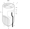
- FIG. 1 It is a perspective view of the wig storage apparatus as a deodorizing apparatus which concerns on embodiment of this invention. It is a perspective view of the ion generator provided in the wig storage device shown in FIG. 1. It is an enlarged view of the area A1 of FIG. It is a figure which shows an example of the shape of the protrusion formed in the wig holding part of the wig storage apparatus shown in FIG. It is a figure which shows the use example of the wig storage apparatus shown in FIG. 1, and shows the example which the ion generator is installed in the 1st installation part, and the wig storage apparatus is used in the state which put it in place. It is a figure which shows the use example of the wig storage apparatus shown in FIG.
- FIG. 1 shows the example which the ion generator is installed in the 2nd installation part, and the wig storage apparatus is used in the state which put it in place.
- FIG. 1 shows the use example of the wig storage apparatus shown in FIG. 1, and shows the example which the ion generator is installed in the 3rd installation part, and the wig storage apparatus is used in a suspended state.
- FIG. 1 shows the use example of the wig storage apparatus shown in FIG. 1, and shows the example which the ion generator removed from the stand part is held by hand, and the wig storage apparatus is used in a state of being placed.
- FIG. 1 shows an image diagram of the cover provided in the wig storage device shown in FIG. 1.
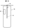
- FIG. 3 is an image diagram showing an example in which a wig storage device to which the cover 30 shown in FIG. 9 is attached is used in a suspended state.
- FIG. 9 is an image diagram showing an example in which the wig storage device to which the cover shown in FIG. 9 is attached is used in a placed state.
- a wig (wig) is used as a symmetrical object, and as a deodorizing device, a wig storage device capable of deodorizing and storing the wig is exemplified.
- FIG. 1 is a perspective view of a wig storage device 1 as a deodorizing device according to the present embodiment.
- the wig storage device 1 includes an ion generator 2 and a stand portion 3 as processing wind generators.
- the ion generator 2 generates ions corresponding to particles by electric discharge and sends out ion wind as processing wind.
- the generated ions include positive (+) ions (eg, H + (H 2 O) m (m is any natural number)) or negative (-) ions (eg, O 2- (H 2 O) n (n). May be any natural number)))) or both.
- the wig is easily damaged if stored in a charged state. Therefore, when the object is a wig, the ion generator 2 that sends out an ion wind that can remove static electricity in addition to deodorizing is effective, and deterioration of the wig can be suppressed by performing static elimination. Further, regardless of the wig, it is preferable to be able to perform sterilization in addition to deodorizing, and the ion generator 2 that sends out an ion wind capable of sterilizing is effective.
- the stand portion 3 holds the wig 4 and allows the ion generator 2 to be detachably installed. As will be described later, the stand portion 3 can install the ion generator 2 at a plurality of locations where the portions of the wig 4 to which the ion wind sent from the ion generator 2 hits are different from each other.
- FIG. 2 is a perspective view of the ion generator 2 provided in the wig storage device 1.
- the ion generator 2 has a bell-shaped case 10 and includes a discharge device (not shown) for generating ions inside the case 10 and a blower fan (not shown).
- An outlet 5 for blowing out ion wind is provided on the circular surface of the case 10 which is the mouth side of the bell shape, and the ion generator 2 is suspended on the curved surface of the case 10 opposite to the side where the outlet 5 is located.
- a hook 6 for lowering and installing is provided.
- the circular surface provided with the outlet 5 will be described as the upper surface
- the curved surface provided with the hook 6 will be described as the lower surface.
- the suction port 7 for sucking the air that becomes the ion wind is provided at the lower part of the side wall of the case 10 located at the lower part of the ion generator 2.
- the suction ports 7 are provided on both sides so as to face each other.
- An air passage is formed between the suction port 7 and the air outlet 5.
- the discharge device is installed so that the generated ions can be released into the air passage. By driving the blower fan, air is sucked from the suction port 7, and the sucked air contains ions and becomes ion wind and is blown out from the outlet 5.
- the blower fan is arranged on the curved surface of the case 10 on the side opposite to the side where the air outlet 5 is located, and the ion generator 2 has the center of gravity on the side opposite to the side where the air outlet 5 is located. have.
- the outlet 5 is located on one side in the radial direction of the upper surface of the ion generator 2, and an operation unit 8 for receiving operations such as turning on and off the ion generator 2 is provided on the other side.
- a recess 10a recessed inward in the radial direction is formed in the upper part of the side wall of the case 10 located below the operation unit 8.
- a protruding portion 10b protruding outward in the radial direction is formed below the operating portion 8.
- a circuit board (not shown) for driving the discharge device and the blower fan is disposed inside the protruding portion 10b.
- a connection portion (not shown) for connecting the power cable 11 is provided on the lower surface 10c of the protruding portion 10b.
- the cable-side connection terminal 12 provided at one end of the power cable 11 is inserted into the connection portion provided on the lower surface 10c from the lower side of the protruding portion 10b, and the board-side connection terminal provided on the circuit board (not). (Illustrated) is connected.
- a dedicated AC adapter (not shown) is provided at the other end of the power cable 11, and AC (alternating current) power is converted to DC (direct current) and supplied to the circuit board.
- a USB terminal (not shown) may be provided at the other end of the power cable 11 so that the USB terminal and the AC adapter can be connected to each other.
- the stand portion 3 has a wig holding portion (object holding portion) 15, an arm portion 16, legs 17, hanging portions 18, and a plurality of installation portions 19.
- the wig holding portion 15 holds the wig 4 from the inside.
- the wig holding portion 15 partially contacts the inner surface of the wig 4 to hold the wig 4.
- the wig holding portion 15 includes a first frame 15a, a second frame 15b, and a fixing ring 15c.
- the first frame 15a and the second frame 15b have an elliptical portion in a side view, and the fixing ring 15c is formed in a ring shape in a plan view.
- the first frame 15a and the second frame 15b are combined so that the major axis of each ellipse is aligned and the minor axis of each ellipse is shifted in the circumferential direction, and the fixing ring 15c is fitted from above in that state. It is fixed.
- the long axis of each ellipse of the first frame 15a and the second frame 15b faces in the vertical direction, and the wig 4 is held from the inside by four frames extending in four directions from the top.
- the contact area between the inner surface of the wig 4 and the wig holding portion 15 is reduced, and more ion wind is applied to the inner surface of the wig 4. Can be done.
- FIG. 3 is an enlarged view of the region A1 of FIG.
- the plurality of protrusions 20 also have a function of preventing the wig 4 from slipping off from the wig holding portion 15.
- the shape of the protrusion 20 may be a rounded shape (for example, hemispherical shape, spherical shape, side view semi-rest shape, side view spherical shape, etc.).
- FIG. 4 is a diagram showing an example of the shape of the protrusion 20.
- the figure shown by reference numeral 1001 is a view of the main part from the middle to the bottom of the stand part 3 from the front surface (the surface showing the ellipse) of the first arm 15a.
- the figure shown by reference numeral 1002 is a view of the main part from the middle to the bottom of the stand part 3 from the front surface (the surface showing the ellipse) of the second arm 15b.
- the figure shown by reference numeral 1003 is an enlarged view of the area A2 of the figure shown by reference numeral 1001, and the figure shown by reference numeral 1004 is an enlarged view of the area A3 of the figure shown by reference numeral 1002.
- the arm portion 16 extends upward toward the wig holding portion 15, and the upper end portion thereof is at a position higher than the wig holding portion 15.
- the arm portion 16 secures a space above the wig holding portion 15 and enables the ion generator 2 to be installed above the wig holding portion 15.
- the arm portion 16 is formed in an arc shape curved toward the outside.
- the arm portion 16 is connected to the first frame 15a constituting the wig holding portion 15, and the arm portion 16 and the first frame 15a are one component.
- the arm portion 16 has a folding structure and is designed to be unfolded during use. As a result, when not in use, the arm portion 16 can be folded and stored compactly, and by extension, the wig storage device 1 can be excellent in storage and portability.
- the leg portion 17 is provided at the lower part of the stand portion 3 and enables the stand portion 3 to stand on its own. By providing the legs 17, the wig storage device 1 can be used in a state of being placed on a desk or the like.
- the leg portion 17 has four legs 17a, the two legs 17a are provided integrally with the arm portion 16 and the first frame 15a, and the other two legs 17a are provided with the second frame 15b. It is provided integrally.
- the hanging portion 18 is a hook-shaped member provided upward on the upper part of the stand portion 3 so that the stand portion 3 can be suspended.
- the wig storage device 1 can be used in a state of being suspended from a bar or the like of a closet (see FIG. 7).
- the hanging portion 18 is provided at the upper end portion of the arm portion 16.
- the hanging portion 18 is preferably provided so that the open portion 18a faces the arm portion 16 side.
- the wig storage device 1 can be easily suspended so that the arm portion 16 side is located on the back side of the closet and the wig holding portion 15 side is located on the front side of the closet with respect to the closet bar or the like. be able to.
- the wig 4 is placed on the wig holding portion 15 and is placed (held) on the wig holding portion 15. The existing wig 4 can be easily taken out.
- the installation unit 19 allows the ion generator 2 to be detachably installed on the stand unit 3.
- the installation unit 19 is provided at a plurality of locations on the stand unit so that the ion generator 2 can be installed at a plurality of locations on the stand unit 3.
- the ion wind sent from the ion generator 2 installed in each installation unit 19 hits different parts of the wig 4.
- the installation units 19 are provided at three locations as the first installation unit 19A to the third installation unit 19C.
- the first installation unit 19A is provided at the lower part of the wig holding unit 15, and the ion generator 2 is installed at the lower part of the wig holding unit 15 with the wind direction facing upward. More specifically, the first installation portion 19A is composed of a recess 23 formed in the central portion of the four legs 17a of the leg portion 17. The inner shape of the recess 23 corresponds to the outer shape of the lower side of the ion generator 2, which will be described later, and the ion generator 2 can be stably held.
- a recess (not shown) is formed in a portion where the first frame 15a and the second frame 15b, which are the bottoms of the recess 23, intersect with each other. There is.
- the hook 6 of the ion generator 2 is adapted to fit in this recess in the state of being installed in the first installation portion 19A.
- the second installation portion 19B is provided at the upper end portion of the arm portion 16, and the ion generator 2 is installed at the upper end portion of the arm portion 16 with the wind direction facing downward. More specifically, the second installation portion 19B is composed of a hook 24 formed downward on the upper end portion of the arm portion 16. By hooking the hook 6 of the ion generator 2 to the hook 24, the ion generator 2 can be held in a suspended state.
- the hook 24 is provided so that the open portion 24a faces the side opposite to the arm portion 16. In the configuration in which the opening portion 24a faces the arm portion 16 side, it is necessary to temporarily dive the ion generator 2 under the hook 24 and then lift and hook the ion generator 2. However, by directing the open portion 24a to the side opposite to the arm portion 16, the ion generator 2 can be easily hooked without diving under the hook 24.
- the arm portion 16 is provided with a hook 21 that can be used to hook the power cable 11 of the ion generator 2 installed in the second installation portion 19B.
- the third installation unit 19C is provided inside the upper part of the wig holding part 15, and the ion generator 2 is installed inside the upper part of the wig holding part 15 with the wind direction facing downward. More specifically, the third installation portion 19C is composed of a hook 25 formed on the second frame 15b of the wig holding portion 15. By hooking the hook 6 of the ion generator 2 to the hook 25, the ion generator 2 can be held in a suspended state.
- the hook 25 is provided so that the open portion 25a faces the side opposite to the arm portion 16.
- the second frame 15b is provided with a hook 22 that can be used to hook the power cable 11 of the ion generator 2 installed in the third installation unit 19C.
- the hook 22 may be provided on the first frame 15a or may be provided on the arm portion 16.
- the arm portion 16, the first frame 15a, the two legs 17a, and the hanging portion 18 are integrally provided, and the second frame 15b and the other two legs 17a are integrally provided.
- the stand portion 3 can be easily assembled by unfolding the folded arm portion 16, combining the first frame 15a with the second frame 15b, and fitting the fixing ring 15c.
- the stand portion 3 By forming the stand portion 3 into a foldable structure and an assembled structure in this way, the portability of the wig storage device 1 can be improved.
- the circular member attached to the upper part of the arm portion 16 is a hanger 27 for hanging the cover 30 (see FIG. 9) described later.
- FIG. 5 shows an example in which the ion generator 2 is installed in the first installation unit 19A and used in a state where the wig storage device 1 is placed.
- the ion generator 2 by installing the ion generator 2 in the first installation portion 19A, the ion wind can be applied from below to the inner surface of the wig 4 held by the wig holding portion 15.
- the inner surface (the surface on the scalp side) of the wig 4 can be effectively deodorized, sterilized, and statically eliminated.
- the scalp odor adhering to the inside of the wig 4 can be effectively deodorized.
- the center of gravity of the ion generator 2 since the center of gravity of the ion generator 2 is located at the lower part in the present embodiment, the ion generator 2 can be stably installed in the first installation unit 19A.
- FIG. 6 shows an example in which the ion generator 2 is installed in the second installation unit 19B and used in a state where the wig storage device 1 is placed.
- the ion generator 2 by installing the ion generator 2 in the second installation portion 19B, the ion wind can be applied from above to the outer surface of the wig 4 held by the wig holding portion 15.
- the outside of the wig 4 can be effectively deodorized, sterilized, and statically eliminated.
- the odor of cigarettes adhering to the outside of the wig 4 can be effectively deodorized.
- FIG. 7 shows an example in which the ion generator 2 is installed in the third installation unit 19C and the wig storage device 1 is used in a suspended state.
- an ion wind is blown from the central portion of the stand portion 3 toward the hair tips of the wig 4 held by the wig holding portion 15. Can be done.
- the ion wind can be applied to the tips of the hair even if the wig 4 is for long hair.
- ions can be effectively distributed to the tips of the hair to deodorize, sterilize, and eliminate static electricity.
- FIG. 8 shows an example in which the ion generator 2 removed from the stand portion 3 is held by hand and used with the wig storage device 1 placed.
- brushing may be performed while applying an ion wind to the wig 4 held by the wig holding portion 15 (while emitting an ion air toward the wig 4).
- the ions can be distributed to the inside of the wig 4 (the back side of the hair) for processing. Further, by this method of use, it is possible to intensively deodorize, sterilize, and eliminate static electricity at any part of the wig 4.
- the hook 6 of the ion generator 2 as a rotary hook, the direction of the outlet 5 can be manually changed when the hook 6 is suspended from the stand portion 3 as shown in FIGS. 6 and 7. It will be possible. This makes it possible to change the convection region of the ions.
- the hook 6 of the ion generator 2 is used as a rotary hook, and a louver is provided at the outlet 5 of the ion generator 2 to allow the ion wind to flow diagonally with respect to the normal direction of the surface on which the outlet 5 is formed. You may make it blow out. With such a configuration, the ion generator 2 can be rotated by the wind force, and the convection area of the ions can be further expanded.
- FIG. 9 is an image diagram of the cover 30 of the wig storage device 1. As shown in FIG. 9, the cover 30 accommodates the stand portion 3 holding the wig 4 and the ion generator 2 inside.
- the cover 30 is formed in a tubular shape with the upper and lower ends closed, and is made of a material that can be softly folded.
- the upper surface of the cover 30 is supported from the inside by a circular hanger 27 attached to the upper part of the arm portion 16.
- the cover 30 has a fastener 31 extending in the vertical direction on the front surface, and can be opened and closed using the fastener 31. Further, the cover 30 has a transparent window 32 made of a transparent material on the front surface, and the inside can be visually recognized through the transparent window 32. A slit 33 is formed on the upper surface of the cover 30 from which the hanging portion 18 (see FIG. 1) of the stand portion 3 is pulled out. A cable opening 34 for drawing out the power cable 11 of the ion generator 2 is formed on the bottom surface of the cover 30.
- the size of such a tubular cover 30 can be, for example, a diameter of 300 mm and a length of 900 mm. When the length is 900 mm, the length of the fastener 31 is preferably about 500 mm in order to facilitate the attachment of the cover 30.
- FIG. 10 is an image diagram showing an example in which the wig storage device 1 to which the cover 30 is attached is used in a suspended state.
- FIG. 11 is an image diagram showing an example in which the wig storage device 1 to which the cover 30 is attached is used in a placed state.
- the figure indicated by reference numeral 1005 shows the front surface
- the figure indicated by reference numeral 1006 shows the back surface.
- a loop 35 for passing the string 36 is provided on the back surface of the cover 30, and the remaining portion of the lower portion of the cover 30 is used as a string when the cover 30 is used in a placed state. It can be summarized using 36.
- the ion generator 2 is exemplified as the processing air generator, but the processing air generator is a particle such as ions, electrons, ozone, radicals, active species, and charged particles (charged particles) due to electric discharge. Any discharge device may be used.
- an ion which is an example of a charged particle, it may be configured to generate both positive ions and negative ions, or it may be configured to generate either positive ions or negative ions.
- a configuration having three locations of the first installation unit 19A to the third installation unit 19C as installation locations of the ion generator 2 is exemplified, but 2 of the first installation unit 19A and the second installation unit 19B It may have a configuration having a location, or a configuration having four or more installation locations.
- a wig is exemplified as a symmetrical object, but the object is not limited to the wig.
- a hat, a helmet, shoes, boots, or the like may be the object. It can be applied by changing the shape of the stand portion 3 according to these objects.
- the configuration in which the wig storage device 1 is provided with one ion generator 2 is exemplified, but the wig storage device 1 may be configured to include a plurality of ion generators 2. In that case, by installing the ion generator 2 at a plurality of installation locations, the effect of each installation location can be obtained at the same time.
- the deodorizing device (wig storage device 1) according to the first aspect of the present invention is a processing wind generator (ion generator 2) that generates particles by discharge and sends out processing air (ion wind) that is air containing the particles. ) And a stand unit 3 for holding the object to be processed by the processing air and detachably installing the processing air generator, and the stand unit 3 is sent out from the processing air generator.
- the processing air generator can be installed at a plurality of locations where the parts of the object to which the processing air hits are different from each other.
- the stand portion 3 holds the object in partial contact with the inner surface of the object.
- the plurality of installation units 19 include a plurality of detachably installed installation units 19, and the plurality of installation units 19 are first installations in which the processing wind generator is installed under the object holding unit with the wind direction facing upward. It is also possible to include a portion 19A and a second installation portion 19B for installing the processing wind generator at the upper end portion of the arm portion 16 with the wind direction facing downward.
- the processing air generator in the first installation unit 19A, the processing air is applied to the inside of the object from the lower side of the object to the object held in the object holding unit.
- the inside of the wig can be deodorized.
- the treated air generator in the second installation unit 19B, the treated air is applied to the object held by the object holding unit from above the object to the outside of the object, and the outside of the object is applied.
- Can be deodorized For example, if the object is a wig, the outside of the wig can be deodorized.
- the plurality of installation units 19 hold the treated wind generator with the wind direction facing downward.
- a third installation portion 19C to be installed inside the upper portion of the portion may be further included.
- the processing wind generator can be further installed in the third installation unit 19C, and by installing it in the third installation unit 19C, the object is held in the object holding unit. It is possible to deodorize the lower side of the object by applying treatment air to the lower side. For example, when the object is a wig for long hair, the treatment wind can be applied to the tips of the long hair.
- the deodorizing device (wig storage device 1) according to the fourth aspect of the present invention is configured to further include a plurality of the treated wind generators in any one of the first to third aspects.
- the treatment wind generator can be installed at a plurality of installation locations at the same time, so that the effect of installing at each installation location can be obtained at the same time.
- the deodorizing device (wig storage device 1) according to the fifth aspect of the present invention further comprises, in any one of the first to fourth aspects, the stand portion 3 in a state of holding the object and the processing wind generating device. It can also be configured to include a cover to be accommodated inside. With the above configuration, it is possible to prevent dust floating in the room from adhering to the object, and the inside of the cover becomes a closed space, the ion concentration can be maintained high, and the treatment effect by ions can be enhanced. can.
- the deodorizing device (wig storage device 1) according to the sixth aspect of the present invention may be configured in any one of the first to fifth aspects, and the stand portion 3 may have a folding structure. With such a configuration, the portability of the deodorizing device can be improved.
- the object is a wig
- the processing wind generator is a processing wind for the object. It is also possible to have a configuration having a function of deodorizing the object by applying the above.
- the method of using the deodorizing device (wig storage device 1) according to the eighth aspect of the present invention is the method of using the deodorizing device (wig storage device 1) according to the seventh aspect, and is removed from the stand portion 3. Brushing the wig is performed while the treated air is discharged from the treated air generator toward the wig held by the stand portion. In this way, by applying the treatment air to the wig while brushing, the treatment air hits the inside of the wig, and the treatment effect by ions can be enhanced.
- Wig storage device deodorant device
- Ion generator treatment wind generator
- Stand part 4 Wig (wig) 5 Air outlet 7 Suction port 8 Operation unit 10
- Case 11 Power cable 12 Cable side connection terminal 15 Wig holding unit 15a 1st frame 15b 2nd frame 15c Fixing ring 16 Arm unit 18 Hanging unit 19 Installation unit 19A 1st installation unit 19B 2nd installation part 19C 3rd installation part 20 Protrusion 30 Cover
Landscapes
- Engineering & Computer Science (AREA)
- Health & Medical Sciences (AREA)
- Chemical & Material Sciences (AREA)
- Combustion & Propulsion (AREA)
- Life Sciences & Earth Sciences (AREA)
- Public Health (AREA)
- Veterinary Medicine (AREA)
- Animal Behavior & Ethology (AREA)
- General Engineering & Computer Science (AREA)
- Mechanical Engineering (AREA)
- General Health & Medical Sciences (AREA)
- Epidemiology (AREA)
- Textile Engineering (AREA)
- General Chemical & Material Sciences (AREA)
- Chemical Kinetics & Catalysis (AREA)
- Disinfection, Sterilisation Or Deodorisation Of Air (AREA)
- Electrotherapy Devices (AREA)
Priority Applications (2)
| Application Number | Priority Date | Filing Date | Title |
|---|---|---|---|
| CN202180062388.6A CN116096435A (zh) | 2020-09-14 | 2021-09-08 | 除臭装置 |
| JP2022547612A JP7761572B2 (ja) | 2020-09-14 | 2021-09-08 | 消臭装置 |
Applications Claiming Priority (2)
| Application Number | Priority Date | Filing Date | Title |
|---|---|---|---|
| JP2020-153763 | 2020-09-14 | ||
| JP2020153763 | 2020-09-14 |
Publications (1)
| Publication Number | Publication Date |
|---|---|
| WO2022054814A1 true WO2022054814A1 (ja) | 2022-03-17 |
Family
ID=80631559
Family Applications (1)
| Application Number | Title | Priority Date | Filing Date |
|---|---|---|---|
| PCT/JP2021/032928 Ceased WO2022054814A1 (ja) | 2020-09-14 | 2021-09-08 | 消臭装置 |
Country Status (3)
| Country | Link |
|---|---|
| JP (1) | JP7761572B2 (https=) |
| CN (1) | CN116096435A (https=) |
| WO (1) | WO2022054814A1 (https=) |
Cited By (1)
| Publication number | Priority date | Publication date | Assignee | Title |
|---|---|---|---|---|
| JP2023141177A (ja) * | 2022-03-23 | 2023-10-05 | 株式会社カネカ | 自動植毛装置 |
Citations (7)
| Publication number | Priority date | Publication date | Assignee | Title |
|---|---|---|---|---|
| JPS4945788U (https=) * | 1972-07-28 | 1974-04-22 | ||
| JP2001137599A (ja) * | 1999-11-17 | 2001-05-22 | Nisshin Kogyo Co Ltd Saitama Plant | 除湿機用乾燥スタンド |
| JP2003240265A (ja) * | 2002-02-18 | 2003-08-27 | Corona Corp | 除湿機 |
| JP2004332142A (ja) * | 2003-05-02 | 2004-11-25 | Kokoro:Kk | カツラなどの脱臭・除菌装置 |
| JP2007016360A (ja) * | 2005-07-11 | 2007-01-25 | Cosmo:Kk | かつら洗浄殺菌消臭乾燥装置 |
| JP3202725U (ja) * | 2015-11-09 | 2016-02-18 | 青暘企業股▲ふん▼有限公司 | 衣類送風乾燥装置 |
| JP2017217981A (ja) * | 2016-06-06 | 2017-12-14 | シャープ株式会社 | 空気清浄機 |
Family Cites Families (7)
| Publication number | Priority date | Publication date | Assignee | Title |
|---|---|---|---|---|
| JPS5127982Y2 (https=) * | 1971-08-02 | 1976-07-15 | ||
| KR100746636B1 (ko) * | 2006-07-06 | 2007-08-06 | 이기형 | 소방용품 건조장치 |
| KR20120135601A (ko) * | 2011-06-07 | 2012-12-17 | 황영민 | 오존 및 플라즈마를 이용한 의류 악취 제거 장치 |
| KR101546650B1 (ko) * | 2014-05-07 | 2015-08-24 | 주식회사 씨크릿우먼 | 통풍수단을 구비한 미용제품 거치대 |
| KR101780032B1 (ko) * | 2017-07-04 | 2017-09-19 | (주)하인스 | 수통 소독기 |
| KR101807471B1 (ko) * | 2017-07-26 | 2017-12-12 | 남윤 | 기능성 가발 유지 관리기 |
| CN108477721A (zh) * | 2018-04-18 | 2018-09-04 | 安徽金瑞祥发制品有限公司 | 一种化纤假发成型装置 |
-
2021
- 2021-09-08 JP JP2022547612A patent/JP7761572B2/ja active Active
- 2021-09-08 WO PCT/JP2021/032928 patent/WO2022054814A1/ja not_active Ceased
- 2021-09-08 CN CN202180062388.6A patent/CN116096435A/zh active Pending
Patent Citations (7)
| Publication number | Priority date | Publication date | Assignee | Title |
|---|---|---|---|---|
| JPS4945788U (https=) * | 1972-07-28 | 1974-04-22 | ||
| JP2001137599A (ja) * | 1999-11-17 | 2001-05-22 | Nisshin Kogyo Co Ltd Saitama Plant | 除湿機用乾燥スタンド |
| JP2003240265A (ja) * | 2002-02-18 | 2003-08-27 | Corona Corp | 除湿機 |
| JP2004332142A (ja) * | 2003-05-02 | 2004-11-25 | Kokoro:Kk | カツラなどの脱臭・除菌装置 |
| JP2007016360A (ja) * | 2005-07-11 | 2007-01-25 | Cosmo:Kk | かつら洗浄殺菌消臭乾燥装置 |
| JP3202725U (ja) * | 2015-11-09 | 2016-02-18 | 青暘企業股▲ふん▼有限公司 | 衣類送風乾燥装置 |
| JP2017217981A (ja) * | 2016-06-06 | 2017-12-14 | シャープ株式会社 | 空気清浄機 |
Cited By (2)
| Publication number | Priority date | Publication date | Assignee | Title |
|---|---|---|---|---|
| JP2023141177A (ja) * | 2022-03-23 | 2023-10-05 | 株式会社カネカ | 自動植毛装置 |
| JP7798255B2 (ja) | 2022-03-23 | 2026-01-14 | 株式会社カネカ | 自動植毛装置 |
Also Published As
| Publication number | Publication date |
|---|---|
| JPWO2022054814A1 (https=) | 2022-03-17 |
| CN116096435A (zh) | 2023-05-09 |
| JP7761572B2 (ja) | 2025-10-28 |
Similar Documents
| Publication | Publication Date | Title |
|---|---|---|
| KR100675254B1 (ko) | 공기 청정 장치 | |
| US7195660B2 (en) | Pillow with air filter | |
| US20060096331A1 (en) | Cleaning device for clothes | |
| WO2022054814A1 (ja) | 消臭装置 | |
| CN109395119A (zh) | 一种口腔科用口腔检查仪器消毒装置 | |
| JPWO2019098100A1 (ja) | 被り物クリーナ | |
| KR200476334Y1 (ko) | 마우스피스 살균 건조기 | |
| KR20120118288A (ko) | 의류보관장치 | |
| KR101639063B1 (ko) | 일체형 탈취 포대를 이용한 휴대용 스타일러 | |
| JP2016220758A (ja) | 衣類処理装置 | |
| JP2022061773A (ja) | 衣類処理装置および制御方法 | |
| JP2009056275A (ja) | 消臭機能付ポールハンガー | |
| JP7761573B2 (ja) | 処理風発生装置 | |
| JP2006149822A (ja) | 衣類乾燥機 | |
| KR102197534B1 (ko) | 층류 유동 공기 배출 기능을 가진 공간 살균기 | |
| KR20120015912A (ko) | 가발용 드라이어 | |
| KR101732945B1 (ko) | 앞치마 소독기 | |
| JPH08228851A (ja) | オゾンによる衣類脱臭装置 | |
| JP2022525181A (ja) | 補綴アクセサリ滅菌器 | |
| KR20210017665A (ko) | 색소폰 살균장치 | |
| JP6502168B2 (ja) | 衣類処理装置 | |
| KR20160146479A (ko) | 송풍 장치가 부설된 접이식 옷걸이, 이와 일체형 탈취 포대를 이용한 휴대용 스타일러 및 이를 이용한 옷 탈취 방법 | |
| CN216439508U (zh) | 具有消毒功能的医用柜 | |
| JP2022067610A (ja) | ドライヤー | |
| CN219829293U (zh) | 一种呼吸气囊储氧袋干燥支架及风干装置 |
Legal Events
| Date | Code | Title | Description |
|---|---|---|---|
| 121 | Ep: the epo has been informed by wipo that ep was designated in this application |
Ref document number: 21866773 Country of ref document: EP Kind code of ref document: A1 |
|
| ENP | Entry into the national phase |
Ref document number: 2022547612 Country of ref document: JP Kind code of ref document: A |
|
| NENP | Non-entry into the national phase |
Ref country code: DE |
|
| 122 | Ep: pct application non-entry in european phase |
Ref document number: 21866773 Country of ref document: EP Kind code of ref document: A1 |