WO2022054719A1 - 判定装置、切削工具システムおよび判定方法 - Google Patents
判定装置、切削工具システムおよび判定方法 Download PDFInfo
- Publication number
- WO2022054719A1 WO2022054719A1 PCT/JP2021/032496 JP2021032496W WO2022054719A1 WO 2022054719 A1 WO2022054719 A1 WO 2022054719A1 JP 2021032496 W JP2021032496 W JP 2021032496W WO 2022054719 A1 WO2022054719 A1 WO 2022054719A1
- Authority
- WO
- WIPO (PCT)
- Prior art keywords
- determination
- cutting
- unit
- cutting insert
- holder
- Prior art date
Links
Images


Classifications
-
- B—PERFORMING OPERATIONS; TRANSPORTING
- B23—MACHINE TOOLS; METAL-WORKING NOT OTHERWISE PROVIDED FOR
- B23B—TURNING; BORING
- B23B27/00—Tools for turning or boring machines; Tools of a similar kind in general; Accessories therefor
-
- B—PERFORMING OPERATIONS; TRANSPORTING
- B23—MACHINE TOOLS; METAL-WORKING NOT OTHERWISE PROVIDED FOR
- B23B—TURNING; BORING
- B23B27/00—Tools for turning or boring machines; Tools of a similar kind in general; Accessories therefor
- B23B27/14—Cutting tools of which the bits or tips or cutting inserts are of special material
- B23B27/16—Cutting tools of which the bits or tips or cutting inserts are of special material with exchangeable cutting bits or cutting inserts, e.g. able to be clamped
-
- B—PERFORMING OPERATIONS; TRANSPORTING
- B23—MACHINE TOOLS; METAL-WORKING NOT OTHERWISE PROVIDED FOR
- B23Q—DETAILS, COMPONENTS, OR ACCESSORIES FOR MACHINE TOOLS, e.g. ARRANGEMENTS FOR COPYING OR CONTROLLING; MACHINE TOOLS IN GENERAL CHARACTERISED BY THE CONSTRUCTION OF PARTICULAR DETAILS OR COMPONENTS; COMBINATIONS OR ASSOCIATIONS OF METAL-WORKING MACHINES, NOT DIRECTED TO A PARTICULAR RESULT
- B23Q17/00—Arrangements for observing, indicating or measuring on machine tools
Definitions
- the present disclosure relates to a determination device, a cutting tool system and a determination method.
- This application claims priority on the basis of Japanese Application Japanese Patent Application No. 2020-151703 filed on September 10, 2020 and incorporates all of its disclosures herein.
- Patent Document 1 Japanese Unexamined Patent Publication No. 2019-166600 discloses the following holders for turning tools. That is, the turning tool holder is a turning tool holder that holds the cutting insert, and is built into the tool body having a pedestal portion extending along the tool axis and mounting the cutting insert at the tip, and the tool body.
- the electric module includes a sensor unit and a battery unit that supplies power to the sensor unit.
- the determination device of the present disclosure includes an acquisition unit that acquires measurement results of a strain sensor attached to a holder that can hold a cutting insert, and the cutting insert in the holder based on the measurement results acquired by the acquisition unit. It is provided with a determination unit for determining the mounting state of the.
- the cutting tool system of the present disclosure includes a holder having an accommodating portion in contact with a cutting insert, a strain sensor attached to the surface of the holder, and a determination device, and the determination device acquires the measurement result of the strain sensor. Then, based on the acquired measurement result, the mounting state of the cutting insert in the holder is determined.
- the determination method of the present disclosure is a determination method in the determination device, and is a determination method in the holder based on a step of acquiring a measurement result of a strain sensor attached to a holder capable of holding a cutting insert and the acquired measurement result. It includes a step of determining the mounting state of the cutting insert.
- One aspect of the present disclosure can be realized not only as a determination device provided with such a characteristic processing unit, but also as a semiconductor integrated circuit that realizes a part or all of the determination device, or processing in the determination device.
- Can be realized as a program for making a computer execute the steps can be realized as a cutting tool system equipped with a judgment device, can be realized as a semiconductor integrated circuit that realizes a part or all of a cutting tool system, and can be cut. It can be realized as a method of processing in a tool system as a step, or as a program for causing a computer to execute a processing step in a cutting tool system.
- FIG. 1 is a diagram showing an example of a configuration of a cutting tool system according to an embodiment of the present disclosure.
- FIG. 2 is a diagram showing a configuration of a management device according to an embodiment of the present disclosure.
- FIG. 3 is a diagram showing a state in which the cutting tool according to the embodiment of the present disclosure is attached to the machine tool.
- FIG. 4 is a diagram showing a configuration of a sensor module according to an embodiment of the present disclosure.
- FIG. 5 is a diagram showing a configuration of a determination device according to an embodiment of the present disclosure.
- FIG. 6 is a diagram showing the time change of the strain value indicated by the measurement information acquired by the acquisition unit in the determination device according to the embodiment of the present disclosure.
- FIG. 1 is a diagram showing an example of a configuration of a cutting tool system according to an embodiment of the present disclosure.
- FIG. 2 is a diagram showing a configuration of a management device according to an embodiment of the present disclosure.
- FIG. 3 is a diagram showing a state
- FIG. 7 is a diagram showing a time change of the adjustment strain value calculated by the determination unit in the determination device according to the embodiment of the present disclosure.
- FIG. 8 is a diagram showing an average adjustment strain value calculated by a determination unit in the determination device according to the embodiment of the present disclosure.
- FIG. 9 is a diagram showing an average adjustment strain value calculated by an abnormality determination unit in the management device according to the embodiment of the present disclosure.
- FIG. 10 is a flowchart defining an example of an operation procedure when the determination device according to the embodiment of the present disclosure determines the mounting state before the start of cutting.
- FIG. 11 is a flowchart defining an example of an operation procedure when the determination device according to the embodiment of the present disclosure determines the mounting state after the start of cutting.
- FIG. 12 is a diagram showing an example of a sequence of determination processing in the cutting tool system according to the embodiment of the present disclosure.
- FIG. 13 is a diagram showing another example of the configuration of the cutting tool system according to the embodiment of the present disclosure.
- the present disclosure has been made to solve the above-mentioned problems, and an object thereof is a determination device capable of realizing an excellent function regarding mounting of a cutting insert in a system capable of monitoring the state of a cutting tool. It is to provide a cutting tool system and a determination method.
- the determination device is based on an acquisition unit that acquires measurement results of a strain sensor attached to a holder that can hold a cutting insert, and the measurement results acquired by the acquisition unit.
- a determination unit for determining the mounting state of the cutting insert in the holder is provided.
- the cutting insert is normally mounted in the holder. It can be automatically detected whether or not it is. Therefore, in a system capable of monitoring the state of the cutting tool, it is possible to realize an excellent function regarding the mounting of the cutting insert.
- the determination unit may determine the mounting state based on the measurement result before the start of cutting using the cutting insert.
- the cutting process can be started after confirming the determination result of the mounting state of the cutting insert. Therefore, for example, when the cutting insert is not normally mounted on the holder, the mounting state of the cutting insert is checked. Cutting can be started after improvement.
- the determination unit may determine the mounting state based on the measurement result after the start of cutting using the cutting insert.
- the determination unit is a non-cutting period during which the cutting edge of the cutting insert is not in contact with the work piece after the start of the cutting process, based on the measurement result after the start of the cutting process. May be specified and the mounting state may be determined based on the measurement result in the non-cutting period.
- the determination device is further based on the measurement result used when the determination unit determines that the cutting insert is attached to the holder before the start of the cutting process.
- the determination unit may determine the mounting state based on the reference value and the measurement result after the start of the cutting process.
- the determination device further includes a state information acquisition unit for acquiring state information indicating that work for attaching the cutting insert to the holder has been performed before the start of the cutting process, and the state information.
- the determination unit includes a determination unit that determines a reference value related to the measurement result based on the measurement result after the state information is acquired by the acquisition unit, and the determination unit is after the start of the reference value and the cutting process.
- the mounting state may be determined based on the measurement result.
- the determination device further includes a control unit that performs a change process for changing the content of the measurement operation of the strain sensor when the determination unit determines that the cutting insert is attached to the holder. There may be.
- the determination device further has a communication unit that transmits the measurement result to another device, and when the determination unit determines that the cutting insert is attached to the holder, the transmission operation by the communication unit is performed. It may be configured to include a control unit that performs a change process for changing the contents.
- a plurality of the strain sensors are attached to the holder, and the determination device further obtains the plurality of strain sensors before the determination unit determines that the cutting insert is attached to the holder. It may be configured to include a control unit for selectively operating some of the strain sensors.
- some strain sensors can be operated to reduce power consumption before the cutting insert is attached to the holder. Therefore, for example, a small-capacity battery placed in a limited space in a cutting tool can be used. In the configuration in which the measurement operation is performed by using the battery, the battery replacement frequency can be reduced by extending the life of the battery.
- control unit determines that the cutting insert is not attached to the holder in the state after the change process, or the measurement result satisfies a predetermined condition. In that case, the state before the change process may be restored.
- the determination device further includes an update unit that performs a process of updating a database of usage information, which is information regarding the use of the cutting insert, according to the determination result of the mounting state by the determination unit. You may.
- the usage time and cutting distance of the cutting insert can be controlled based on the timing when the cutting insert is attached to the holder and the timing when the cutting insert is removed from the holder.
- by appropriately managing the replacement timing of the cutting insert it is possible to suppress the increase in consumption and cost of the cutting insert due to the replacement of the cutting insert that can still be used.
- the database stores the usage information for each identification information of the cutting insert, and the determination device further acquires the identification information of the cutting insert attached to the holder.
- the updating unit may perform a process of updating the contents of the usage information corresponding to the identification information acquired by the identification information acquisition unit in the database.
- the database can be managed in association with the identification information of the cutting insert. Therefore, for example, when the cutting insert used in the past is attached to the holder and used again, the usage history of the cutting insert is displayed. It is possible to grasp and accurately manage the usage time and cutting distance.
- the cutting tool system includes a holder having an accommodating portion with which the cutting insert is in contact, a strain sensor attached to the surface of the holder, and a determination device.
- the measurement result of the strain sensor is acquired, and the mounting state of the cutting insert in the holder is determined based on the acquired measurement result.
- the cutting insert is normally mounted in the holder. It can be automatically detected whether or not it is. Therefore, in a system capable of monitoring the state of the cutting tool, it is possible to realize an excellent function regarding the mounting of the cutting insert.
- the strain sensor may be attached at a position exceeding the width of the accommodating portion from the tip of the cutting edge of the cutting insert in the side view of the holder from which the cutting insert is removed.
- the determination method according to the embodiment of the present disclosure is a determination method in the determination device, which is a step of acquiring a measurement result of a strain sensor attached to a holder capable of holding a cutting insert, and the acquired measurement. A step of determining the attachment state of the cutting insert in the holder based on the result is included.
- the cutting insert is normally mounted in the holder. It can be automatically detected whether or not it is. Therefore, in a system capable of monitoring the state of the cutting tool, it is possible to realize an excellent function regarding the mounting of the cutting insert.
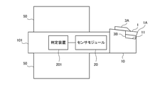
- FIG. 1 is a diagram showing an example of a configuration of a cutting tool system according to an embodiment of the present disclosure.
- the cutting tool system 401 includes a cutting tool 101, a wireless master unit 300, and a management device 301.
- the wireless master unit 300 is connected to the management device 301 by wire, for example.
- the management device 301 can communicate with a machine tool (not shown) via a wireless transmission line or a wired transmission line.
- the management device 301 may be a part of the machine tool.
- the sensor module 20 and the determination device 201 are provided in the holder 10 of the cutting tool 101.
- the sensor module 20 and the determination device 201 are connected to each other via, for example, a wire.
- the sensor module 20 generates a sensor packet storing measurement information indicating the measurement result of the strain sensor attached to the holder 10, and transmits the generated sensor packet to the determination device 201.
- the determination device 201 When the determination device 201 receives the sensor packet from the sensor module 20, it acquires measurement information from the received sensor packet and determines the mounting state of the cutting insert 1 in the holder 10 based on the acquired measurement information. The determination device 201 generates a determination packet storing determination information indicating the determination result, and transmits a radio signal including the generated determination packet to the wireless master unit 300.
- the determination device 201 when the determination device 201 receives the sensor packet from the sensor module 20, the determination device 201 transmits a radio signal including the sensor packet to the wireless master unit 300.
- the wireless master unit 300 is, for example, an access point.
- the wireless master unit 300 acquires a sensor packet included in the wireless signal received from the determination device 201 and relays it to the management device 301. Further, the wireless master unit 300 acquires the determination packet included in the wireless signal received from the determination device 201 and relays it to the management device 301.
- the management device 301 When the management device 301 receives the sensor packet from the determination device 201 via the wireless master unit 300, the management device 301 acquires measurement information from the received sensor packet. For example, the management device 301 determines the state of the cutting edge of the cutting insert 1 based on the acquired measurement information, and performs a process of displaying the determination result or notifying the user by voice.
- the management device 301 when the management device 301 receives the determination packet from the determination device 201 via the wireless master unit 300, the management device 301 acquires the determination information from the received determination packet.
- the management device 301 performs a process of displaying the determination result indicated by the acquired determination information or notifying the user by voice.
- the determination device 201 and the wireless master unit 300 conform to, for example, ZigBee (registered trademark) compliant with IEEE 802.15.4, Bluetooth (registered trademark) compliant with IEEE 802.15.1, and IEEE 802.15.3a.
- Wireless communication is performed using a communication protocol such as UWB (Ultra Wide Band).
- UWB Ultra Wide Band
- a communication protocol other than the above may be used between the determination device 201 and the wireless master unit 300.
- the cutting tool system 401 is not limited to the configuration including one cutting tool 101, but may be configured to include a plurality of cutting tools 101.
- FIG. 2 is a diagram showing a configuration of a management device according to an embodiment of the present disclosure.
- the management device 301 includes a communication unit 310, an abnormality determination unit 320, a management unit 330, a reception unit 340, a notification unit 350, and a storage unit 360.
- the abnormality determination unit 320, the management unit 330, the reception unit 340, and the notification unit 350 are realized by, for example, a processor such as a CPU (Central Processing Unit) and a DSP (Digital Signal Processor).
- the communication unit 310 is realized by, for example, a communication circuit such as a communication IC (Integrated Circuit).
- the storage unit 360 is, for example, a non-volatile memory.
- the reception unit 340 accepts operations performed by the user on input devices such as a mouse and a keyboard according to the screen displayed on the display unit of the management device 301.
- the communication unit 310 When the communication unit 310 receives the determination packet from the determination device 201 via the wireless master unit 300, the communication unit 310 acquires the determination information from the received determination packet and outputs the acquired determination information to the notification unit 350.
- the notification unit 350 When the notification unit 350 receives the determination information from the communication unit 310, the notification unit 350 performs a process of displaying the determination result indicated by the received determination information or notifying the user by voice.
- the communication unit 310 when the communication unit 310 receives the sensor packet from the determination device 201 via the wireless master unit 300, the communication unit 310 acquires measurement information from the received sensor packet and stores the acquired measurement information in the storage unit 360.
- the abnormality determination unit 320 determines the state of the cutting edge of the cutting insert 1 based on the measurement information in the storage unit 360, and outputs the determination information indicating the determination result to the notification unit 350.
- the notification unit 350 When the notification unit 350 receives the determination information from the abnormality determination unit 320, the notification unit 350 performs a process of displaying the determination result indicated by the received determination information or notifying the user by voice.
- the user when the user performs the mounting work for mounting the cutting insert 1 on the holder 10 before the start of the cutting process, the user has performed the mounting work and transfers the ID (Identifier) of the cutting insert 1 to the management device 301. Perform the input operation.
- the reception unit 340 accepts the operation of the user, generates state information indicating that the installation work has been performed, outputs the status information to the communication unit 310, and generates identification information indicating the ID of the cutting insert 1 for communication. Output to unit 310.
- the communication unit 310 When the communication unit 310 receives the status information from the reception unit 340, the communication unit 310 generates a status packet storing the received status information and transmits the generated status packet to the determination device 201 via the wireless master unit 300.
- the communication unit 310 when the communication unit 310 receives the identification information from the reception unit 340, the communication unit 310 generates an identification packet storing the received identification information, and transmits the generated identification packet to the determination device 201 via the wireless master unit 300.
- the storage unit 360 stores a usage database which is a database of usage information which is information regarding the use of the cutting insert 1.
- the usage database stores usage information for each ID of the cutting insert 1.
- the storage unit 360 uses the ID of the cutting insert 1, the cumulative usage time of the cutting insert 1, the cumulative cutting distance using the cutting insert 1, the remaining usable time of the cutting insert 1, and the remaining cutting of the cutting insert 1. It stores a usage database showing the correspondence between the possible distance, the load amount fluctuation value in the machine tool, the number of load amount fluctuations in the machine tool, and the judgment result in the abnormality determination unit 320.
- the management unit 330 calculates the usage time and cutting distance of the cutting insert 1 based on the measurement information in the storage unit 360, and updates the usage database in the storage unit 360 based on the calculated usage time and cutting distance.
- FIG. 3 is a diagram showing a state in which the cutting tool according to the embodiment of the present disclosure is attached to the machine tool.
- the cutting tool 101 is fixed by sandwiching the holder 10 with the tool post 50 in the machine tool from above and below.
- the holder 10 is a square shank having a square cross section.
- the upper surface and the lower surface of the holder 10 are sandwiched between the tool rests 50.
- the cutting tool 101 is, for example, a turning tool used for machining a rotating work piece, and is attached to a machine tool such as a lathe.
- the holder 10 can hold the cutting insert 1. That is, the cutting tool 101 is a so-called throw-away tool. More specifically, the holder 10 includes an accommodating portion 11 and fixing members 3A and 3B. The fixing members 3A and 3B hold the cutting insert 1.
- the accommodating portion 11 is a recess formed in the holder 10.
- the cutting insert 1 has a polygonal shape such as a triangle, a square, a rhombus, and a pentagon when viewed from above.
- the upper surface of the cutting insert 1 is a rake face.
- the corner portion of the cutting insert 1 is a cutting edge 1A.
- the cutting insert 1 has, for example, a through hole formed in the center of the upper surface of the cutting insert 1.
- the cutting insert 1 is fixed to the accommodating portion 11 in the holder 10 by the fixing members 3A and 3B.
- the accommodating portion 11 has a bottom surface and a side surface that intersects the bottom surface.
- the bottom surface of the accommodating portion 11 is a surface on which the fixing member 3B is placed.
- the cutting insert 1 is positioned at a predetermined position by being fixed by the fixing members 3A and 3B in a state where at least one of the cutting insert 1 and the fixing member 3B is in contact with at least one of the bottom surface and the side surface thereof. Will be done.
- the holder 10 may be configured not to include the fixing member 3B.
- the cutting insert 1 is fixed to the accommodating portion 11 in the holder 10 by the fixing member 3A. Further, the cutting insert 1 may be fastened and fixed to the accommodating portion 11 by a screw inserted into the through hole.
- the cutting tool 101 is, for example, a tool for milling used for machining a fixed work piece, and may be attached to a machine tool such as a milling machine.
- the holder 10 in the cutting tool 101 for milling can hold one or a plurality of cutting inserts 1.
- FIG. 4 is a diagram showing a configuration of a sensor module according to an embodiment of the present disclosure.
- the sensor module 20 includes a power supply circuit 21, strain sensors 22A and 22B, a processing unit 23, a communication unit 24, and a storage unit 25.
- each of the strain sensors 22A and 22B is also referred to as a strain sensor 22.
- the sensor module 20 is activated, for example, by a user operation.
- the processing unit 23 is realized by, for example, a processor such as a CPU and a DSP.
- the communication unit 24 is realized by a communication circuit such as a communication IC.
- the storage unit 25 is, for example, a non-volatile memory.
- the strain sensor 22 is attached to the holder 10.
- the strain sensor 22 is attached to the surface of the holder 10 with an adhesive.
- the strain sensor 22 is mounted on the surface of the holder 10 in the vicinity of the cutting insert 1.
- the strain sensor 22 is the surface of the holder 10 at a position exceeding the width of the accommodating portion 11 from the tip of the cutting edge 1A in the side view of the holder 10 from which the cutting insert 1 is removed, and is in the vicinity of the cutting insert 1. Attached to. That is, the distance between the tip of the cutting edge 1A of the cutting insert 1 and the strain sensor 22 in the direction parallel to the axis of the holder 10 is larger than the width of the accommodating portion 11.
- the width of the accommodating portion 11 is the length of the accommodating portion 11 in the direction parallel to the axis of the holder 10.
- the distance between the tip of the cutting edge 1A of the cutting insert 1 and the strain sensor 22 means the distance between the tip of the cutting edge 1A of the cutting insert 1 and the center of the strain sensor 22.
- the distance between the tip of the cutting edge 1A of the cutting insert 1 and the strain sensor 22 is preferably 5 mm or more, more preferably 10 mm or more.
- the distance between the tip of the cutting edge 1A of the cutting insert 1 and the strain sensor 22 is preferably 30 mm or less, more preferably 25 mm or less.
- the plurality of strain sensors 22 are attached to different surfaces of the holder 10.
- the two strain sensors 22 are attached to two adjacent surfaces of the surface of the holder 10, respectively.
- the strain sensor 22A is attached to the upper surface of the holder 10
- the strain sensor 22B is attached to the side surface of the holder 10.
- the holder 10 is a square shank, but the holder 10 is not limited to this.
- the holder 10 may be a so-called round shank.
- the two strain sensors 22 are mounted at positions separated by preferably 75 ° to 105 °, more preferably 85 ° to 95 °, and even more preferably 90 ° along the outer peripheral surface of the holder 10.
- the sensor module 20 is not limited to the configuration including the two strain sensors 22, but may be configured to include one or three or more strain sensors 22. Further, the sensor module 20 may be configured to include other sensors such as an acceleration sensor, a sound sensor, and a temperature sensor in addition to the strain sensor 22. Further, the mounting position of the strain sensor 22 on the holder 10 is not particularly limited. The strain sensor 22 may be mounted at any position on the surface of the holder 10 as long as the effects of the present disclosure can be obtained.
- the power supply circuit 21 includes, for example, a power storage device such as a primary battery, a secondary battery, a solar cell, or a capacitor.
- the power supply circuit 21 supplies the power of the power storage device to the strain sensor 22, the storage unit 25, the processing unit 23, and the communication unit 24.
- the power supply circuit 21 first supplies electric power to the storage unit 25, the processing unit 23, and the communication unit 24.
- the communication unit 24 receives the control information C from the determination device 201.
- the control information C the sensor ID of the strain sensor 22 to be operated, the sampling frequency F indicating the frequency of AD (Analog Digital) conversion of the analog signal output by the strain sensor 22, and the cycle for transmitting the sensor packet are used.
- the transmission cycle T shown is included.
- the communication unit 24 receives the control information C from the determination device 201, the communication unit 24 outputs the control information C to the processing unit 23.
- the processing unit 23 When the processing unit 23 receives the control information C from the communication unit 24, the processing unit 23 controls the power supply circuit 21 to start supplying electric power to the strain sensor 22 indicated by the control information C.
- the strain sensor 22 operates by being supplied with electric power from the power supply circuit 21.
- the strain sensor 22 that has started operation measures the strain and outputs an analog signal indicating the measured strain to the processing unit 23.
- the processing unit 23 AD-converts the analog signal received from the strain sensor 22 at the timing according to the sampling frequency F indicated by the control information C described above, and generates a strain value ⁇ which is a digital value after conversion.
- the processing unit 23 generates strain values ⁇ a and ⁇ b by AD-converting the analog signals received from the strain sensors 22A and 22B, respectively.
- the strain value ⁇ a shows the measurement result of the strain on the upper surface of the holder 10
- the strain value ⁇ b shows the measurement result of the strain on the side surface of the holder 10.
- the processing unit 23 When the processing unit 23 generates the strain values ⁇ a and ⁇ b, the processing unit 23 generates the measurement information S including the strain values ⁇ a and ⁇ b and the measurement time ts and stores it in the storage unit 25.
- the processing unit 23 acquires one or more measurement information S from the storage unit 25 at the transmission timing according to the transmission cycle T indicated by the control information C described above, and the communication unit 24 stores the sensor packet in which the acquired measurement information S is stored. Output to.
- the communication unit 24 transmits the sensor packet received from the processing unit 23 to the determination device 201.
- FIG. 5 is a diagram showing a configuration of a determination device according to an embodiment of the present disclosure.
- the determination device 201 controls the communication unit 210, the first acquisition unit 231, the state information acquisition unit 232, the identification information acquisition unit 233, the determination unit 240, and the determination unit 250.
- a unit 260, a notification unit 270, an update unit 280, and a storage unit 290 are provided.
- the first acquisition unit 231, the status information acquisition unit 232, the identification information acquisition unit 233, the determination unit 240, the determination unit 250, the control unit 260, the notification unit 270, and the update unit 280 are realized by a processor such as a CPU and a DSP, for example. Will be done.
- the communication unit 210 is realized by a communication circuit such as a communication IC.
- the storage unit 290 is, for example, a non-volatile memory.
- the determination device 201 is activated, for example, by a user operation.
- the communication unit 210 transmits the measurement result of the strain sensor 22 to another device, for example, the management device 301. More specifically, when the communication unit 210 receives the sensor packet from the sensor module 20 during the processing period Tp described later, the communication unit 210 transmits the received sensor packet to the management device 301 via the wireless master unit 300.
- the first acquisition unit 231 acquires cutting information, which is information on machining conditions,, for example, before starting cutting.
- the first acquisition unit 231 uses the name of the holder 10 used for cutting, the name of the cutting insert 1 used for cutting, the name of the work piece to be cut, and the cutting as cutting information.
- Acquire cutting parameter information including information indicating conditions.
- the first acquisition unit 231 acquires NC (Numerical Control) programs, CAM (Computer Aided Manufacturing) data, and the like as information indicating cutting conditions.
- the communication unit 210 receives the cutting parameter information as described above from a control unit (not shown) in the machine tool via a wireless transmission line, and outputs the received cutting parameter information to the first acquisition unit 231.
- the first acquisition unit 231 When the first acquisition unit 231 receives the cutting parameter information from the communication unit 210, the first acquisition unit 231 stores the received cutting parameter information in the storage unit 290.
- the first acquisition unit 231 is not limited to the configuration in which cutting parameter information is received from the machine tool via the communication unit 210.
- the first acquisition unit 231 may be configured to receive cutting parameter information from a control unit (not shown) in the management device 301 via the communication unit 210.
- the first acquisition unit 231 may be configured to acquire cutting parameter information from a database (not shown) that stores cutting parameter information.
- the database is provided in a machine tool, a management device 301, a determination device 201 or another device.
- the first acquisition unit 231 accumulates the acquired cutting parameter information in the database when new cutting parameter information is acquired from the machine tool.
- the first acquisition unit 231 may be configured to receive cutting parameter information from an input device (not shown) that accepts an input operation of cutting parameter information by the user.
- the input device may be provided in a machine tool, a management device 301, a determination device 201 or another device, or may be a single device, that is, a dedicated device.
- the state information acquisition unit 232 acquires state information indicating that the work for attaching the cutting insert 1 to the holder 10 has been performed before the start of the cutting process.
- the communication unit 210 when the communication unit 210 receives the status packet from the management device 301 via the wireless master unit 300, the communication unit 210 acquires the status information from the received status packet and outputs the acquired status information to the status information acquisition unit 232. ..
- the status information acquisition unit 232 When the status information acquisition unit 232 receives the status information from the communication unit 210, the status information acquisition unit 232 stores the received status information in the storage unit 290.
- the identification information acquisition unit 233 acquires the identification information of the cutting insert 1 attached to the holder 10.
- the communication unit 210 when the communication unit 210 receives the identification packet from the management device 301 via the wireless master unit 300, the communication unit 210 acquires the identification information from the received identification packet and outputs the acquired identification information to the identification information acquisition unit 233. ..
- the identification information acquisition unit 233 When the identification information acquisition unit 233 receives the identification information from the communication unit 210, the identification information acquisition unit 233 stores the received identification information in the storage unit 290.
- the first acquisition unit 231 acquires the measurement result of the strain sensor 22.
- the communication unit 210 acquires the measurement information S from the sensor packet received from the sensor module 20, and outputs the acquired measurement information S to the first acquisition unit 231.
- the first acquisition unit 231 When the first acquisition unit 231 receives the measurement information S from the communication unit 210, the first acquisition unit 231 stores the received measurement information S in the storage unit 290.
- control unit 260 selectively operates a part of the strain sensors 22 in the sensor module 20 before the determination unit 250 determines that the cutting insert 1 is attached to the holder 10.
- the control unit 260 determines, for example, the sensor ID of the strain sensor 22A to be operated and the frequency of AD conversion of the analog signal output by the strain sensor 22A.
- the control information C1 including the sampling frequency F1 shown and the transmission cycle T1 indicating the cycle in which the sensor packet should be transmitted is generated, and the generated control information C1 is output to the communication unit 210.
- the communication unit 210 When the communication unit 210 receives the control information C1 from the control unit 260, the communication unit 210 transmits the received control information C1 to the sensor module 20.
- the communication unit 210 After transmitting the control information C1 to the sensor module 20, the communication unit 210 receives the sensor packet transmitted from the sensor module 20 at the transmission timing according to the transmission cycle T1, and AD conversion of the sampling frequency F1 from the received sensor packet.
- the measurement information S1 including the strain value ⁇ a generated by is acquired, and the acquired measurement information S1 is output to the first acquisition unit 231.
- the first acquisition unit 231 receives the measurement information S1 from the communication unit 210, and stores the received measurement information S1 in the storage unit 290.
- the communication unit 210 transmits the received sensor packet to the management device 301 via the wireless master unit 300.
- the determination unit 250 determines the mounting state of the cutting insert 1 in the holder 10 based on the measurement result acquired by the first acquisition unit 231.
- the determination unit 250 acquires the measurement information S from the storage unit 290, and determines the mounting state based on the acquired measurement information S. For example, the determination unit 250 determines whether or not the cutting insert 1 is attached to the holder 10 based on the measurement information S.
- the state in which the cutting insert 1 is not attached to the holder 10 means that the cutting insert 1 does not exist between the fixing members 3A and 3B in the holder 10 and the cutting insert between the fixing members 3A and 3B. 1 is present and the cutting insert 1 is not normally attached.
- the determination unit 250 acquires the measurement information S from the storage unit 290 and sets the mounting state based on the acquired measurement information S. judge. Then, the determination unit 250 notifies the control unit 260, the notification unit 270, and the update unit 280 of the determination result.
- the notification unit 270 When the notification unit 270 receives the determination information from the determination unit 250, the notification unit 270 outputs the received determination information to the communication unit 210.
- the communication unit 210 When the communication unit 210 receives the determination information from the notification unit 270, it generates a determination packet storing the received determination information and transmits the generated determination packet to the management device 301 via the wireless master unit 300.
- the determination unit 250 determines the mounting state of the cutting insert 1 based on the measurement result of the strain sensor 22 before the start of the cutting process using the cutting insert 1. For example, the determination unit 250 determines whether or not the cutting insert 1 is attached to the holder 10 before the start of the cutting process.
- the determination unit 250 estimates in advance the processing period Tp, which is the period during which cutting processing using the cutting tool 101 is performed, based on the cutting information in the storage unit 290.
- the determination unit 250 acquires the measurement information S1 including the measurement time ts before the processing period Tp from the storage unit 290, the determination unit 250 determines whether or not the cutting insert 1 is attached to the holder 10 based on the acquired measurement information S1. judge.
- the storage unit 290 stores the upper limit threshold value UL1 and the lower limit threshold value LL1 regarding the strain value ⁇ a indicated by the measurement information S1 in the state before the cutting insert 1 is attached to the holder 10.
- the determination unit 250 determines whether or not the cutting insert 1 is attached to the holder 10 based on the comparison result between the strain value ⁇ a and the upper limit threshold value UL1 and the lower limit threshold value LL1 in the storage unit 290.
- the determination unit 250 determines that the cutting insert 1 is not attached to the holder 10 when the strain value ⁇ a is equal to or less than the upper limit threshold value UL1 and is equal to or more than the lower limit threshold value LL1.
- the determination unit 250 determines that the cutting insert 1 is attached to the holder 10.
- the determination unit 250 determines the mounting state of the cutting insert 1, it outputs determination information indicating the determination result to the control unit 260, the notification unit 270, and the update unit 280.
- (Change process 1) For example, when the determination unit 250 determines that the cutting insert 1 is attached to the holder 10, the control unit 260 performs a change process for changing the content of the measurement operation of the strain sensor 22. Further, for example, when the determination unit 250 determines that the cutting insert 1 is attached to the holder 10, a change process for changing the content of the transmission operation by the communication unit 210 is performed.
- control unit 260 when the control unit 260 receives the determination information indicating the determination result indicating that the cutting insert 1 is attached to the holder 10 from the determination unit 250, the control unit 260 is added to the strain sensor 22A already operating in the sensor module 20. Then, the strain sensor 22B is operated. Further, the control unit 260 changes the frequency at which the processing unit 23 in the sensor module 20 AD-converts the analog signal from the strain sensor 22A from the sampling frequency F1 to the sampling frequency F2. Further, the control unit 260 changes the transmission cycle of the sensor packet from the sensor module 20 to the determination device 201 from the transmission cycle T1 to the transmission cycle T2, so that the sensor packet from the communication unit 210 in the determination device 201 to the management device 301. Change the transmission cycle of.
- the control unit 260 indicates each sensor ID of the strain sensors 22A and 22B, a sampling frequency F2 indicating the frequency of AD conversion of the analog signal output by each strain sensor 22, and a cycle for transmitting the sensor packet.
- the control information C2 including the transmission cycle T2 is generated, and the generated control information C2 is output to the communication unit 210.
- the sampling frequency F1 is smaller than the sampling frequency F2, and the transmission cycle T1 is longer than the transmission cycle T2. Therefore, the power consumption before the determination unit 250 determines that the cutting insert 1 is attached to the holder 10 is smaller than the power consumption after the determination unit 250 determines that the cutting insert 1 is attached to the holder 10.
- the communication unit 210 When the communication unit 210 receives the control information C2 from the control unit 260, the communication unit 210 transmits the received control information C2 to the sensor module 20.
- the communication unit 210 After transmitting the control information C2 to the sensor module 20, the communication unit 210 receives the sensor packet transmitted from the sensor module 20 at the transmission timing according to the transmission cycle T2, and AD-converts the sampling frequency F2 from the received sensor packet.
- the measurement information S2 including the strain values ⁇ a and ⁇ b generated by is acquired, and the acquired measurement information S2 is output to the first acquisition unit 231.
- the first acquisition unit 231 receives the measurement information S2 from the communication unit 210, and stores the received measurement information S2 in the storage unit 290.
- the communication unit 210 transmits the received sensor packet to the management device 301 via the wireless master unit 300.
- the determination unit 240 is a reference regarding the measurement result of the strain sensor 22 based on the measurement result used when the determination unit 250 determines that the cutting insert 1 is attached to the holder 10 before the start of the cutting process. Determine the value.
- the determination unit 240 determines the reference value based on one or a plurality of measurement information S2 stored in the storage unit 290 by the first acquisition unit 231 before the start of the cutting process.
- the determination unit 240 acquires a plurality of measurement information S2 from the storage unit 290, calculates the average value of the strain value ⁇ a indicated by each acquired measurement information S2 as the reference value Sta, and the strain indicated by each measurement information S2.
- the average value of the values ⁇ b is calculated as the reference value Stb.
- the determination unit 240 stores the calculated reference values Sta and Stb in the storage unit 290.
- the determination unit 240 determines a reference value regarding the measurement result based on the measurement result after the state information is acquired by the state information acquisition unit 232.
- the determination unit 240 when the state information is stored in the storage unit 290 by the state information acquisition unit 232 before the start of the cutting process, the determination unit 240 is stored in the storage unit 290 by the first acquisition unit 2311. Alternatively, the reference value is determined based on the plurality of measurement information S2.
- the determination unit 240 acquires a plurality of measurement information S2 from the storage unit 290, calculates the average value of the strain value ⁇ a indicated by each acquired measurement information S2 as the reference value Sta, and the strain indicated by each measurement information S2.
- the average value of the values ⁇ b is calculated as the reference value Stb, and the calculated reference values Sta and Stb are stored in the storage unit 290.
- the determination unit 250 determines the mounting state of the cutting insert 1 based on the measurement result of the strain sensor 22 after the start of the cutting process using the cutting insert 1.
- the determination unit 250 acquires the measurement information S2 including the measurement time ts after the start of the machining period Tp from the storage unit 290, the determination unit 250 holds the holder based on the strain values ⁇ a and ⁇ b indicated by the acquired measurement information S2. It is determined whether or not the cutting insert 1 is attached to the 10.
- FIG. 6 is a diagram showing the time change of the strain value indicated by the measurement information acquired by the acquisition unit in the determination device according to the embodiment of the present disclosure.
- FIG. 6 shows the time change of the strain value ⁇ a indicated by the measurement information S2 during cutting.
- the horizontal axis is time and the vertical axis is strain [ ⁇ ].
- the strain value ⁇ a is a value between about 437.5 ⁇ and about 445 ⁇ .
- the strain value ⁇ a is a value including the strain ⁇ ax applied when the strain sensor 22A is installed in the holder 10.
- the strain value ⁇ b is a value including the strain ⁇ bx applied when the strain sensor 22B is installed in the holder 10.
- the strain ⁇ ax is a value that varies depending on the installation state of the strain sensor 22A
- the strain ⁇ bx is a value that varies depending on the installation state of the strain sensor 22B. Therefore, it is not easy to accurately determine the mounting state based on the comparison result between the common threshold value and the strain values ⁇ a and ⁇ b.
- the strain value ⁇ a changes as the cutting insert 1 cuts the work piece even when the mounting state such as tightening of the cutting insert 1 by the fixing members 3A and 3B is kept constant.
- the strain value ⁇ b may also change as the cutting insert 1 cuts the work piece, even when the mounting state of the cutting insert 1 is kept constant. Therefore, it is not easy to accurately determine the mounting state based on the strain values ⁇ a and ⁇ b in the machining period Tp including the period in which the cutting insert 1 cuts the work piece and the period in which the work piece is not cut.
- the determination unit 250 determines the mounting state of the cutting insert 1 based on the reference values Sta, Stb determined by the determination unit 240 and the measurement result after the start of the cutting process.
- the determination unit 250 is a non-cutting period Tn, which is a period during which the cutting edge 1A of the cutting insert 1 is not in contact with the work piece after the start of the cutting process, based on the measurement result after the start of the cutting process. Is determined, and the mounting state of the cutting insert 1 is determined based on the measurement result in the non-cutting period Tn.
- the determination unit 250 calculates the adjustment strain value used for determining the mounting state of the cutting insert 1 based on the reference values Sta and Stb in the measurement information S2 and the storage unit 290.
- the determination unit 250 calculates the difference between the strain value ⁇ a indicated by the measurement information S2 and the reference value Sta in the storage unit 290 as the adjusted strain value ⁇ as, and the strain value ⁇ b and the storage unit 290 indicated by the measurement information S2.
- the difference from the reference value Stb in is calculated as the adjusted strain value ⁇ bs.
- FIG. 7 is a diagram showing a time change of the adjustment strain value calculated by the determination unit in the determination device according to the embodiment of the present disclosure.
- FIG. 7 shows the time change of the adjusted strain value ⁇ as.
- the horizontal axis is time and the vertical axis is strain [ ⁇ ].
- the adjusted strain value ⁇ as calculated by the determination unit 250 is a value based on the reference value Sta, that is, the strain value ⁇ a before the start of cutting, and the installed state of the strain sensor 22A in the holder 10. It is a value excluding the strain ⁇ ax according to.
- the storage unit 290 stores the upper limit threshold value CUa and the lower limit threshold value CLa regarding the adjustment strain value ⁇ as.
- the determination unit 250 measures the strain value ⁇ a used for calculating the adjustment strain value ⁇ as based on the comparison result between the calculated adjustment strain value ⁇ as and the upper limit threshold value CUa and the lower limit threshold value CLa in the storage unit 290. It is determined whether the time ts is the time within the cutting period Tc or the non-cutting period Tn, which is the period during which the cutting edge 1A of the cutting insert 1 is in contact with the work piece.
- the determination unit 250 determines that the measurement time ts is within the cutting period Tc and calculates it. Discard the adjusted strain values ⁇ as and ⁇ bs.
- the determination unit 250 determines that the measurement time ts is within the non-cutting period Tn, and calculates the adjustment strain.
- the values ⁇ as and ⁇ bs are stored in the storage unit 290 in association with the measurement time ts.
- the determination unit 250 each time the determination unit 250 stores the measurement information S2 in the storage unit 290 by the first acquisition unit 231 during the machining period Tp, the determination unit 250 acquires the measurement information S2 and calculates the adjustment strain values ⁇ as and ⁇ bs. It is determined whether the corresponding measurement time ts is a time within the cutting period Tc or the non-cutting period Tn.
- the determination unit 250 determines the mounting state based on the adjustment strain values ⁇ as and ⁇ bs stored in the storage unit 290.
- the determination unit 250 has an average adjusted strain value A ⁇ as, which is a moving average of the adjusted strain values ⁇ as, and an average adjusted strain value, which is a moving average of the adjusted strain values ⁇ bs, based on the adjusted strain values ⁇ as and ⁇ bs in the storage unit 290. Calculate A ⁇ bs.
- the storage unit 290 stores the determination upper limit threshold value ThUa and the determination lower limit threshold value ThLa regarding the average adjustment strain value A ⁇ as, and the determination upper limit threshold value ThUb and the determination lower limit threshold value ThLb regarding the average adjustment strain value A ⁇ bs. is doing.
- the judgment upper limit threshold ThUa, the judgment lower limit threshold ThLa, the judgment upper limit threshold ThUb, and the judgment lower limit threshold ThLb are set in advance for each cutting insert 1, each holder 10, or each cutting condition. Will be done.
- the user reproduces a state in which a mounting defect has occurred in the cutting insert 1 in advance, and based on the average adjustment strain values A ⁇ as and A ⁇ bs calculated by the determination unit 250, the determination upper limit threshold value ThUa and the determination lower limit
- the threshold value ThLa, the determination upper limit threshold value ThUb, and the determination lower limit threshold value ThLb are set and registered in the storage unit 290.
- the determination unit 250 compares the average adjustment strain value A ⁇ as with the determination upper limit threshold value ThUa and the determination lower limit threshold value ThLa in the storage unit 290, and also compares the average adjustment strain value ThLa.
- the value A ⁇ bs is compared with the determination upper limit threshold value ThUb and the determination lower limit threshold value ThLb in the storage unit 290, and the mounting state is determined based on each comparison result.
- FIG. 8 is a diagram showing an average adjustment strain value calculated by a determination unit in the determination device according to the embodiment of the present disclosure.
- FIG. 8 shows a set of a plurality of average adjusted strain values A ⁇ as and A ⁇ bs calculated based on the measurement information S2 in the non-cutting period Tn.
- the horizontal axis is the strain [ ⁇ ] indicated by the average adjusted strain value A ⁇ bs
- the vertical axis is the strain [ ⁇ ] indicated by the average adjusted strain value A ⁇ as.
- the average adjustment strain value A ⁇ as is equal to or less than the determination upper limit threshold value ThUa and the determination lower limit threshold value ThLa or more, and the average adjustment strain value A ⁇ bs is equal to or less than the determination upper limit threshold value ThUb. If it is equal to or higher than the determination lower limit threshold value ThLb, it is determined that the cutting insert 1 is attached to the holder 10.
- the average adjustment strain value A ⁇ as is larger than the determination upper limit threshold value ThUa and the average adjustment strain value A ⁇ as is less than the determination lower limit threshold value ThLa
- the average adjustment strain value A ⁇ bs is the upper limit of the determination. If it is larger than the value ThUb, or if the average adjustment strain value A ⁇ bs is less than the determination lower limit threshold value ThLb, it is determined that the cutting insert 1 is not attached to the holder 10.
- the determination unit 250 determines the mounting state of the cutting insert 1, it outputs determination information indicating the determination result to the control unit 260, the notification unit 270, and the update unit 280.
- the determination unit 250 determines that the cutting process is completed. More specifically, the determination unit 250 determines that the cutting process has been completed when the amount of change of the strain values ⁇ a and ⁇ b indicated by the measurement information S2 per unit time is less than the predetermined value in a certain period of the predetermined length. ..
- the determination unit 250 determines that the cutting process has been completed, the determination unit 250 outputs the end information to the control unit 260.
- the control unit 260 stops the strain sensor 22B in the sensor module 20. .. Further, the control unit 260 changes the frequency at which the processing unit 23 in the sensor module 20 AD-converts the analog signal from the strain sensor 22A from the sampling frequency F2 to the sampling frequency F1. Further, the control unit 260 changes the transmission cycle of the sensor packet from the sensor module 20 to the determination device 201 from the transmission cycle T2 to the transmission cycle T1, so that the sensor packet from the communication unit 210 in the determination device 201 to the management device 301. Change the transmission cycle of.
- control unit 260 determines the sensor ID of the strain sensor 22A, the sampling frequency F1 indicating the frequency of AD conversion of the analog signal output by the strain sensor 22A, and the transmission cycle T1 indicating the cycle in which the sensor packet should be transmitted.
- the including control information C1 is generated, and the generated control information C1 is output to the communication unit 210.
- the communication unit 210 When the communication unit 210 receives the control information C1 from the control unit 260, the communication unit 210 transmits the received control information C1 to the sensor module 20.
- the communication unit 210 After transmitting the control information C1 to the sensor module 20, the communication unit 210 receives the sensor packet transmitted from the sensor module 20 at the transmission timing according to the transmission cycle T1, and AD conversion of the sampling frequency F1 from the received sensor packet.
- the measurement information S1 including the strain value ⁇ a generated by is acquired, and the acquired measurement information S1 is output to the first acquisition unit 231.
- the first acquisition unit 231 receives the measurement information S1 from the communication unit 210, and stores the received measurement information S1 in the storage unit 290.
- the communication unit 210 transmits the received sensor packet to the management device 301 via the wireless master unit 300.
- the update unit 280 performs a process of updating the database of usage information, which is information regarding the use of the cutting insert 1, according to the determination result of the mounting state by the determination unit 250. For example, the update unit 280 performs a process of updating the contents of the usage information corresponding to the identification information acquired by the identification information acquisition unit 233 in the database.
- the update unit 280 receives the identification information from the storage unit 290. It acquires and generates removal information indicating that the cutting insert 1 having the ID indicated by the identification information has been removed from the holder 10.
- the update unit 280 outputs the generated removal information to the communication unit 210.
- the communication unit 210 includes the removal information received from the update unit 280 in the determination packet and transmits it to the management device 301 via the wireless master unit 300.
- the management unit 330 in the management device 301 receives the removal information from the determination device 201 via the wireless master unit 300 and the communication unit 310, the removal received based on the measurement information in the storage unit 360.
- the usage time and cutting distance of the cutting insert 1 indicated by the information are calculated, and the usage database in the storage unit 360 is updated based on the calculated usage time and cutting distance.
- the communication unit 310 in the management device 301 receives the sensor packet from the determination device 201 via the wireless master unit 300, the communication unit 310 acquires the measurement information S2 from the received sensor packet and stores the acquired measurement information S2 in the storage unit 360.
- the abnormality determination unit 320 determines the state of the cutting edge 1A of the cutting insert 1 based on the measurement information S2 in the storage unit 360.
- the abnormality determination unit 320 calculates the adjustment strain values ⁇ as and ⁇ bs in the same manner as the determination unit 250 in the determination device 201, and the corresponding measurement time ts is a time within any of the cutting period Tc and the non-cutting period Tn. Is determined.
- the abnormality determination unit 320 determines that the measurement time ts is within the non-cutting period Tn, the calculated adjustment strain values ⁇ as and ⁇ bs are discarded.
- the abnormality determination unit 320 determines that the measurement time ts is within the cutting period Tc
- the calculated adjustment strain values ⁇ as and ⁇ bs are stored in the storage unit 360 in association with the measurement time ts.
- the abnormality determination unit 320 acquires the measurement information S2 and calculates the adjustment strain values ⁇ as and ⁇ bs, and the corresponding measurement time ts is set. It is determined whether the time is within the cutting period Tc or the non-cutting period Tn.
- the abnormality determination unit 320 determines the state of the cutting edge 1A of the cutting insert 1 based on the adjustment strain values ⁇ as and ⁇ bs stored in the storage unit 360.
- FIG. 9 is a diagram showing an average adjustment strain value calculated by an abnormality determination unit in the management device according to the embodiment of the present disclosure.
- FIG. 9 shows a set of a plurality of average adjusted strain values A ⁇ as and A ⁇ bs calculated based on the measurement information S2 in the cutting period Tc.
- the horizontal axis is the strain [ ⁇ ] indicated by the average adjusted strain value A ⁇ bs
- the vertical axis is the strain [ ⁇ ] indicated by the average adjusted strain value A ⁇ as.
- the average adjustment strain value A ⁇ as is equal to or less than the second upper limit threshold value ThUa2 and the second lower limit threshold value is ThLa2 or more, and the average adjustment strain value A ⁇ bs is the second upper limit.
- the threshold value is ThUb2 or less and the second lower limit threshold value is ThLb2 or more, it is determined that the cutting edge 1A of the cutting insert 1 is normal.
- the average adjusted strain value A ⁇ as is larger than the second upper limit threshold value ThUa2 and the average adjusted strain value A ⁇ as is less than the second lower limit threshold value ThLa2
- the average adjusted strain value A ⁇ bs is the second.
- the second upper limit threshold ThUa2 is 4 [ ⁇ ]
- the second lower limit threshold ThLa2 is 3.7 [ ⁇ ]
- the second upper limit threshold ThUb2 is 1 [ ⁇ ].
- the second lower threshold value ThLb2 is 0.7 [ ⁇ ].
- the abnormality determination unit 320 may use the arithmetic mean, synergistic mean, pruned mean, variance, standard deviation, strain degree, sharpness, median value, maximum value, minimum value, covariance, and phase of the strain values indicated by the measurement information.
- the index value of at least one of the number of relations, the partial correlation coefficient, the factor loading, and the principal component score is calculated.
- the abnormality determination unit 320 preferably calculates an index value of at least one of arithmetic mean, geometric mean, pruning average, variance, and standard deviation.
- the abnormality determination unit 320 performs preprocessing such as noise processing, FFT (Fast Fourier Transform) processing, vector transformation, and dimensional compression on the calculated index value.
- the abnormality determination unit 320 determines the state of the cutting edge 1A of the cutting insert 1 based on the comparison result between the index value after the pretreatment and a predetermined threshold value.
- the abnormality determination unit 320 determines the state of the cutting edge 1A of the cutting insert 1, it outputs the abnormality determination information indicating the determination result to the notification unit 350. Further, when the abnormality determination unit 320 determines that an abnormality has occurred in the cutting edge 1A, the abnormality determination unit 320 records the determination result in the storage unit 290.
- the notification unit 350 Upon receiving the abnormality determination information from the abnormality determination unit 320, the notification unit 350 performs a process of displaying the determination result indicated by the received abnormality determination information or notifying the user by voice.
- Each device in the cutting tool system according to the embodiment of the present disclosure includes a computer including a memory, and an arithmetic processing unit such as a CPU in the computer is a program including a part or all of each step of the following flowchart and sequence. Is read from the memory and executed. The programs of these plurality of devices can be installed from the outside. The programs of these plurality of devices are distributed in a state of being stored in a recording medium.
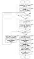
- FIG. 10 is a flowchart defining an example of an operation procedure when the determination device according to the embodiment of the present disclosure determines the mounting state before the start of cutting.
- the determination device 201 acquires cutting information, for example, before starting cutting, and estimates the processing period Tp based on the acquired cutting information (step S102).
- the determination device 201 includes control information including the sensor ID of the sensor 22A, the sampling frequency F1 indicating the frequency of AD conversion of the analog signal output by the strain sensor 22A, and the transmission cycle T1 indicating the cycle in which the sensor packet should be transmitted.
- C1 is transmitted to the sensor module 20 (step S104).
- the determination device 201 listens for the sensor packet transmitted from the sensor module 20 at the transmission timing according to the transmission cycle T1 (NO in step S106) and receives the sensor packet (YES in step S106), the determination device 201 receives the sensor packet from the received sensor packet. Acquire the measurement information S1 (step S108).
- the determination device 201 determines the mounting state of the cutting insert 1 in the holder 10 based on the measurement information S1. More specifically, the determination device 201 compares the strain value ⁇ a indicated by the measurement information S1 including the measurement time ts before the machining period Tp with the upper limit threshold value UL1 and the lower limit threshold value LL1 (step S110). ..
- the determination device 201 determines that the cutting insert 1 is not attached to the holder 10 (NO). Step S114).
- the determination device 201 transmits a determination packet containing the determination information indicating the determination result to the management device 301 (step S116).
- the determination device 201 waits for a new sensor packet from the sensor module 20 (NO in step S106).
- the determination device 201 determines that the cutting insert 1 is attached to the holder 10 (step S118). ..
- the determination device 201 transmits a determination packet containing the determination information indicating the determination result to the management device 301 (step S120).
- the determination device 201 has a sensor ID of each of the strain sensors 22A and 22B, a sampling frequency F2 indicating the frequency of AD conversion of the analog signal output by each strain sensor 22, and a transmission cycle indicating a cycle in which the sensor packet should be transmitted.
- the control information C2 including T2 is transmitted to the sensor module 20 (step S122).
- the determination device 201 receives the sensor packet transmitted from the sensor module 20 at the transmission timing according to the transmission cycle T2, and uses the average value of the strain values ⁇ a indicated by each measurement information S2 in the plurality of sensor packets as the reference value Sta. The calculation is performed, and the average value of the strain values ⁇ b indicated by the respective measurement information S2 is calculated as the reference value Stb (step S124).
- the determination device 201 stores the calculated reference values Sta and Stb in the storage unit 290 (step S126).
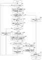
- FIG. 11 is a flowchart defining an example of an operation procedure when the determination device according to the embodiment of the present disclosure determines the mounting state after the start of cutting.
- step S204 when the determination device 201 listens for the sensor packet transmitted from the sensor module 20 at the transmission timing according to the transmission cycle T2 (NO in step S202) and receives the sensor packet (YES in step S202). , The measurement information S2 is acquired from the received sensor packet, and the sensor packet is transmitted to the management device 301 via the wireless master unit 300 (step S204).
- the amount of change of the strain values ⁇ a and ⁇ b indicated by the measurement information S2 including the measurement time ts after the start of the machining period Tp is less than the predetermined value in the period of the predetermined length. If (NO in step S206), it is determined that the cutting process has been completed (step S208).
- the determination device 201 includes control information including the sensor ID of the sensor 22A, the sampling frequency F1 indicating the frequency of AD conversion of the analog signal output by the strain sensor 22A, and the transmission cycle T1 indicating the cycle in which the sensor packet should be transmitted.
- C1 is transmitted to the sensor module 20 (step S210).
- the determination device 201 sets the adjusted strain value ⁇ as based on the strain values ⁇ a and ⁇ b indicated by the measurement information S2 including the measurement time ts after the start of the machining period Tp and the reference values Sta and Stb in the storage unit 290. , ⁇ bs are calculated (step S212).
- the determination device 201 compares the calculated adjustment strain value ⁇ as with the upper limit threshold value CUa and the lower limit threshold value CLa in the storage unit 290 (step S214).
- the determination device 201 determines that the measurement time ts is a time within the cutting period Tc. Then, the calculated adjustment strain values ⁇ as and ⁇ bs are discarded (step S218).
- the determination device 201 waits for a new sensor packet from the sensor module 20 (NO in step S202).
- the determination device 201 determines that the measurement time ts is a time within the non-cutting period Tn. Then, the calculated adjusted strain values ⁇ as and ⁇ bs are stored in the storage unit 290 in association with the measurement time ts, and the average adjusted strain values A ⁇ as and A ⁇ bs are calculated based on the adjusted strain values ⁇ as and ⁇ bs in the storage unit 290. (Step S220).
- the determination device 201 compares the calculated average adjustment strain value A ⁇ as with the determination upper limit threshold value ThUa and the determination lower limit threshold value ThLa in the storage unit 290, and stores the calculated average adjustment strain value A ⁇ bs.
- the determination upper limit threshold value ThUb and the determination lower limit threshold value ThLb in the unit 290 are compared (step S222).
- the average adjustment strain value A ⁇ bs is the upper limit of the determination.
- ThUb or when the average adjustment strain value A ⁇ bs is less than the determination lower limit threshold value ThLb (NO in step S224)
- the determination device 201 generates removal information indicating that the cutting insert 1 has been removed from the holder 10, and transmits the generated removal information and the determination information indicating the determination result to the management device 301 (step S228).
- the determination device 201 includes control information including the sensor ID of the sensor 22A, the sampling frequency F1 indicating the frequency of AD conversion of the analog signal output by the strain sensor 22A, and the transmission cycle T1 indicating the cycle in which the sensor packet should be transmitted.
- C1 is transmitted to the sensor module 20 (step S210).
- the average adjustment strain value A ⁇ as is equal to or less than the determination upper limit threshold value ThUa and the determination lower limit threshold value ThLa or more
- the average adjustment strain value A ⁇ bs is equal to or less than the determination upper limit threshold value ThUb and the determination lower limit threshold value.
- the determination device 201 transmits the determination information indicating the determination result to the management device 301 (step S232).
- the determination device 201 waits for a new sensor packet from the sensor module 20 (NO in step S202).
- FIG. 12 is a diagram showing an example of a sequence of determination processing in the cutting tool system according to the embodiment of the present disclosure.
- the determination device 201 acquires cutting information before the start of cutting (step S302).
- the determination device 201 estimates the machining period Tp based on the cutting information (step S304).
- the determination device 201 includes control information including the sensor ID of the sensor 22A, the sampling frequency F1 indicating the frequency of AD conversion of the analog signal output by the strain sensor 22A, and the transmission cycle T1 indicating the cycle in which the sensor packet should be transmitted.
- C1 is transmitted to the sensor module 20 (step S306).
- the sensor module 20 transmits a sensor packet containing the measurement information S1 including the strain value ⁇ a to the determination device 201 at the transmission timing according to the transmission cycle T1 before the start of cutting (step S308).
- the determination device 201 receives the sensor packet from the sensor module 20, and acquires the measurement information S1 from the received sensor packet (step S310).
- the determination device 201 determines the mounting state of the cutting insert 1 in the holder 10 based on the measurement information S1. For example, the determination device 201 determines that the cutting insert 1 is attached to the holder 10 (step S312).
- the determination device 201 transmits a determination packet containing the determination information indicating the determination result to the management device 301 (step S314).
- the determination device 201 has a sensor ID of each of the strain sensors 22A and 22B, a sampling frequency F2 indicating the frequency of AD conversion of the analog signal output by each strain sensor 22, and a transmission cycle T2 indicating a cycle in which the sensor packet should be transmitted.
- the control information C2 including the above is transmitted to the sensor module 20 (step S316).
- the management device 301 receives a judgment packet from the judgment device 201, performs judgment information from the received judgment packet, and performs a process of displaying the judgment result indicated by the acquired judgment information or notifying the user by voice (step S318). ).
- the sensor module 20 transmits a sensor packet containing measurement information S2 including strain values ⁇ a and ⁇ b to the determination device 201 at the transmission timing according to the transmission cycle T2 (step S320).
- the determination device 201 receives the sensor packet from the sensor module 20, and acquires the measurement information S2 from the received sensor packet (step S322).
- the determination device 201 transmits the sensor packet to the management device 301 via the wireless master unit 300 (step S324).
- the determination device 201 determines the mounting state of the cutting insert 1 in the holder 10 based on the measurement information S2 (step S326).
- the management device 301 acquires measurement information S2 from the sensor packet received from the determination device 201, and determines the state of the cutting edge 1A of the cutting insert 1 based on the acquired measurement information S2 (step S328).
- the determination device 201 transmits a determination packet containing the determination information indicating the determination result to the management device 301 (step S330).
- the management device 301 receives the judgment packet from the judgment device 201, acquires the judgment information from the received judgment packet, and performs a process of displaying the judgment result indicated by the acquired judgment information or notifying the user by voice. Further, the management device 301 performs a process of displaying the determination result of the state of the cutting edge 1A or notifying the user by voice (step S332).
- the sensor module 20 transmits a new sensor packet to the determination device 201 at the transmission timing according to the transmission cycle T2 (step S334).
- the determination unit 250 is configured to determine the mounting state of the cutting insert 1 before the start of the cutting process and after the start of the cutting process. It is not limited to. The determination unit 250 may be configured to determine the mounting state before the start of the cutting process and after the start of the cutting process, while not determining the mounting state on the other side.
- the determination unit 250 determines the non-cutting period Tn based on the measurement result of the strain sensor 22 during cutting, and obtains the above measurement result in the non-cutting period Tn. Based on this, the configuration is such that the mounting state of the cutting insert 1 is determined, but the present invention is not limited to this.
- the determination unit 250 may be configured not to determine the non-cutting period Tn. In this case, the determination unit 250 determines, for example, the mounting state of the cutting insert 1 based on the measurement result of the strain sensor 22 during the machining period Tp.
- the determination unit 250 is configured to calculate the average adjustment strain values A ⁇ as and A ⁇ bs, but the present invention is not limited to this.
- the determination unit 250 may be configured not to calculate the average adjustment strain values A ⁇ as and A ⁇ bs.
- the determination unit 250 determines, for example, the mounting state of the cutting insert 1 based on the adjustment strain values ⁇ as and ⁇ bs instead of the average adjustment strain values A ⁇ as and A ⁇ bs.
- the determination unit 250 determines, for example, the mounting state of the cutting insert 1 based on the comparison result between the adjusted strain values ⁇ as and ⁇ bs and a predetermined threshold value.
- the determination device 201 is configured to include the determination unit 240, but the present invention is not limited to this.
- the determination device 201 may be configured not to include the determination unit 240.
- the determination unit 250 determines, for example, the mounting state of the cutting insert 1 based on the moving average of the strain values ⁇ a, ⁇ b or the strain values ⁇ a, ⁇ b instead of the adjusted strain values ⁇ as, ⁇ bs.
- the determination unit 250 is configured to calculate the adjusted strain values ⁇ as and ⁇ bs based on the reference values Sta and Stb in the measurement information S2 and the storage unit 290. However, it is not limited to this.
- the determination unit 250 may be configured to calculate the adjusted strain values ⁇ as and ⁇ bs based on the measurement information S2 and the reference values Sta and Stb determined by the user.
- the user performs an operation of inputting the reference values Sta and Stb to the management device 301.
- the reception unit 340 in the management device 301 receives the operation of the user, generates reference value information indicating the reference values Sta and Stb, and outputs the reference value information to the communication unit 310.
- the communication unit 310 receives the reference value information from the reception unit 340
- the communication unit 310 generates a reference value packet storing the received reference value information and transmits it to the determination device 201 via the wireless master unit 300.
- the communication unit 210 in the determination device 201 acquires the reference value information from the reference value packet received from the management device 301 and stores it in the storage unit 290.
- the determination unit 250 calculates the adjustment strain values ⁇ as and ⁇ bs based on the measurement information S2 in the storage unit 290 and the reference values Sta and Stb indicated by the reference value information.
- the strain sensor 22 when the control unit 260 receives the determination information indicating the determination result indicating that the cutting insert 1 is attached to the holder 10 from the determination unit 250, the strain sensor 22
- the configuration is such that a change process for changing the content of the measurement operation is performed, but the present invention is not limited to this.
- the control unit 260 may be configured not to perform the above change processing.
- the control unit 260 when the control unit 260 receives the determination information indicating the determination result indicating that the cutting insert 1 is attached to the holder 10 from the determination unit 250, the control unit 260 receives the determination information.
- the configuration is such that a change process for changing the content of the transmission operation by the communication unit 210 is performed, but the present invention is not limited to this.
- the control unit 260 may be configured not to perform the above change processing.
- the control unit 260 has the strain sensor 22A among the plurality of strain sensors 22 before the determination unit 250 determines that the cutting insert 1 is attached to the holder 10.
- the control unit 260 may be configured to operate all the strain sensors 22 in the sensor module 20 before the determination unit 250 determines that the cutting insert 1 is attached to the holder 10.
- the control unit 260 determines that the cutting insert 1 is not attached to the holder 10 by the determination unit 250 in the state after the change processing is performed.
- the configuration is such that the state is returned to the state before the change process, but the present invention is not limited to this.
- the control unit 260 determines that the cutting insert 1 is not attached to the holder 10 by the determination unit 250, or the measurement result of the strain sensor 22 satisfies a predetermined condition. It may be configured to return to the state before the change processing, while not returning to the state before the change processing on the other side.
- the determination device 201 is configured to include the update unit 280, but the present invention is not limited to this.
- the determination device 201 may be configured not to include the update unit 280.
- the determination device 201 is configured to include the identification information acquisition unit 233, but the present invention is not limited to this.
- the determination device 201 may be configured not to include the identification information acquisition unit 233.
- the updating unit 280 generates, for example, removal information indicating that the cutting insert 1 used in the cutting process has been removed from the holder 10 and outputs the information to the communication unit 210.
- the holder 10 is configured to have a substantially square pillar shape, but the present invention is not limited to this.
- the holder 10 may have a structure other than a substantially quadrangular prism.
- the holder 10 may have a structure having a substantially cylindrical shape.
- the plurality of strain sensors 22 are mounted on the surface of the holder 10 at intervals of 45 ° or more around the central axis of the holder 10.
- the strain sensors 22A and 22B are mounted on the surface of the holder 10 at a distance of 45 ° from each other around the central axis of the holder 10.
- control unit 260 receives determination information indicating a determination result indicating that the cutting insert 1 is attached to the holder 10 from the determination unit 250 and performs a change process.
- the control unit 260 may be configured to perform a change process according to a user's operation.
- the cutting tool 101 is configured to include the determination device 201, but the present invention is not limited to this.
- the determination device 201 may be configured to be provided outside the cutting tool 101.
- FIG. 13 is a diagram showing another example of the configuration of the cutting tool system according to the embodiment of the present disclosure.
- the determination device 201 may be a part of the management device 301.
- the communication unit 24 in the sensor module 20 transmits the sensor packet to the determination device 201 via the wireless master unit 300.
- abnormal noise may occur during cutting, or abnormalities such as changes in the machined surface properties of the work piece may occur. There is. If such an abnormality occurs during cutting, the cause of the abnormality is to interrupt the cutting process, check the state of the cutting edge 1A of the cutting insert 1, or check the mounting state of the cutting insert 1. It is necessary to investigate, and the production efficiency is reduced. Therefore, a technique capable of determining the mounting state of the cutting insert 1 is desired.
- Patent Documents 1 to 4 use a vibration sensor, an acceleration sensor, or the like as sensors, and use such sensors to determine the mounting state of the cutting insert 1 in the holder 10. It is difficult.
- the first acquisition unit 231 acquires the measurement result of the strain sensor 22 attached to the holder 10 capable of holding the cutting insert 1.
- the determination unit 250 determines the mounting state of the cutting insert 1 in the holder 10 based on the measurement result acquired by the first acquisition unit 231.
- the cutting tool system 401 includes a holder 10 having an accommodating portion 11 in contact with the cutting insert 1, a strain sensor attached to the surface of the holder 10, and a determination device 201.
- the determination device 201 acquires the measurement result of the strain sensor 22, and determines the mounting state of the cutting insert 1 in the holder 10 based on the acquired measurement result.
- the determination method according to the embodiment of the present disclosure is the determination method in the determination device 201.
- the determination device 201 acquires the measurement result of the strain sensor 22 attached to the holder 10 capable of holding the cutting insert 1.
- the determination device 201 determines the mounting state of the cutting insert 1 in the holder 10 based on the acquired measurement result.
- the holder 10 is, for example, by a configuration and a method for determining the mounting state of the cutting insert 1 in the holder 10. Whether or not the cutting insert 1 is normally attached can be automatically detected.
- the determination device 201 the cutting tool system 401, and the determination method according to the embodiment of the present disclosure, it is possible to realize an excellent function regarding the attachment of the cutting insert 1 in the system capable of monitoring the state of the cutting tool 101. ..
- the acquisition unit that acquires the measurement results of the strain sensor attached to the holder that can hold the cutting insert, A determination unit that determines the mounting state of the cutting insert in the holder based on the measurement result acquired by the acquisition unit. It is equipped with a communication unit that transmits the measurement results to other devices.
- the acquisition unit acquires cutting information, which is information on machining conditions, before starting cutting.
- the determination unit estimates a processing period, which is a period during which cutting is performed, based on the cutting information acquired by the acquisition unit.
- the communication unit is a determination device that transmits the measurement result to the other device during the processing period estimated by the determination unit.
- the acquisition unit that acquires the measurement results of the strain sensor attached to the holder that can hold the cutting insert, A determination unit for determining the mounting state of the cutting insert in the holder based on the measurement result acquired by the acquisition unit is provided.
- the acquisition unit and the determination unit are determination devices realized by a processor.
- Cutting insert 3A, 3B Fixing member 10 Holder 11 Accommodating unit 20 Sensor module 21 Power supply circuit 22, 22A, 22B Strain sensor 23 Processing unit 24 Communication unit 25 Storage unit 50 Cutting tool stand 101 Cutting tool 201 Judgment device 210 Communication unit 231 Acquisition unit 232 Status information acquisition unit 233 Identification information acquisition unit 240 Determination unit 250 Judgment unit 260 Control unit 270 Notification unit 280 Update unit 290 Storage unit 300 Wireless master unit 301 Management device 310 Communication unit 320 Abnormality determination unit 330 Management unit 340 Reception unit 350 Notification unit 360 Storage unit 401 Cutting tool system
Landscapes
- Engineering & Computer Science (AREA)
- Mechanical Engineering (AREA)
- Cutting Tools, Boring Holders, And Turrets (AREA)
- Machine Tool Sensing Apparatuses (AREA)
- Arrangements For Transmission Of Measured Signals (AREA)
Priority Applications (1)
| Application Number | Priority Date | Filing Date | Title |
|---|---|---|---|
| JP2022519503A JP7157397B2 (ja) | 2020-09-10 | 2021-09-03 | 判定装置、切削工具システムおよび判定方法 |
Applications Claiming Priority (2)
| Application Number | Priority Date | Filing Date | Title |
|---|---|---|---|
| JP2020-151703 | 2020-09-10 | ||
| JP2020151703 | 2020-09-10 |
Publications (1)
| Publication Number | Publication Date |
|---|---|
| WO2022054719A1 true WO2022054719A1 (ja) | 2022-03-17 |
Family
ID=80631803
Family Applications (1)
| Application Number | Title | Priority Date | Filing Date |
|---|---|---|---|
| PCT/JP2021/032496 WO2022054719A1 (ja) | 2020-09-10 | 2021-09-03 | 判定装置、切削工具システムおよび判定方法 |
Country Status (2)
| Country | Link |
|---|---|
| JP (1) | JP7157397B2 (en, 2012) |
| WO (1) | WO2022054719A1 (en, 2012) |
Citations (3)
| Publication number | Priority date | Publication date | Assignee | Title |
|---|---|---|---|---|
| WO2010061567A1 (ja) * | 2008-11-27 | 2010-06-03 | Ntn株式会社 | 遠隔操作型アクチュエータ |
| JP2019209420A (ja) * | 2018-06-04 | 2019-12-12 | 株式会社日立製作所 | 切削加工システム、及び情報処理装置 |
| JP2020104257A (ja) * | 2018-12-25 | 2020-07-09 | 日立金属株式会社 | 切削工具の異常検知装置、および異常検知方法 |
Family Cites Families (3)
| Publication number | Priority date | Publication date | Assignee | Title |
|---|---|---|---|---|
| US4292865A (en) * | 1977-08-15 | 1981-10-06 | Chunghorng R. Liu | Tool holder for varying tool rake angle |
| JPH04101744A (ja) * | 1990-08-10 | 1992-04-03 | Yamazaki Mazak Corp | 自動加工装置の工具交換装置及び制御方法 |
| JPH0447905U (en, 2012) * | 1990-08-30 | 1992-04-23 |
-
2021
- 2021-09-03 JP JP2022519503A patent/JP7157397B2/ja active Active
- 2021-09-03 WO PCT/JP2021/032496 patent/WO2022054719A1/ja active Application Filing
Patent Citations (3)
| Publication number | Priority date | Publication date | Assignee | Title |
|---|---|---|---|---|
| WO2010061567A1 (ja) * | 2008-11-27 | 2010-06-03 | Ntn株式会社 | 遠隔操作型アクチュエータ |
| JP2019209420A (ja) * | 2018-06-04 | 2019-12-12 | 株式会社日立製作所 | 切削加工システム、及び情報処理装置 |
| JP2020104257A (ja) * | 2018-12-25 | 2020-07-09 | 日立金属株式会社 | 切削工具の異常検知装置、および異常検知方法 |
Also Published As
| Publication number | Publication date |
|---|---|
| JPWO2022054719A1 (en, 2012) | 2022-03-17 |
| JP7157397B2 (ja) | 2022-10-20 |
Similar Documents
| Publication | Publication Date | Title |
|---|---|---|
| JP7276673B2 (ja) | 分析装置、提供装置、判定方法、提供方法、判定プログラムおよび提供プログラム | |
| US9186765B2 (en) | Monitoring method and monitoring apparatus for machine tool, and machine tool | |
| US7676945B2 (en) | Modular measurement probe | |
| CN109623494B (zh) | 一种三合一传感器夹具及多模态刀具磨损状态监测系统 | |
| WO2018119845A1 (zh) | 数控机床的状态检测方法及系统 | |
| WO2021241150A1 (ja) | 管理装置、表示処理方法および表示処理プログラム | |
| CN106425686A (zh) | 一种数控机床刀具磨损监测方法及系统 | |
| US20200004221A1 (en) | Method and system for tool life monitoring and management in a cnc environment | |
| JP7635738B2 (ja) | 切削工具、工具システムおよび通信制御方法 | |
| US20220288739A1 (en) | Sensor system, wireless terminal, and wireless communication apparatus | |
| WO2022054719A1 (ja) | 判定装置、切削工具システムおよび判定方法 | |
| JP2014058017A (ja) | 放電加工機のデータ収集システム | |
| KR102799959B1 (ko) | 공작기계의 공구 정보관리 장치 및 방법 | |
| CN209466035U (zh) | 一种三合一传感器夹具及多模态刀具磨损状态监测系统 | |
| CN102221620A (zh) | 快速检测测试条件的系统和方法 | |
| EP4541507A1 (en) | Anomaly detection system, anomaly detection device, anomaly detection method, and computer program | |
| Suprock et al. | A low cost wireless tool tip vibration sensor for milling | |
| JP2020163567A (ja) | 情報処理装置、情報処理方法、および情報処理システム | |
| JP7036292B1 (ja) | 判定装置、切削工具システムおよび判定方法 | |
| JP2013226909A (ja) | 車内省電力制御装置 | |
| WO2022239189A1 (ja) | 加工条件管理システム、加工制御装置、加工システム、および加工プログラム | |
| CN213021372U (zh) | 一种单面大圆机针筒组件的检测装置 | |
| WO2021241149A1 (ja) | 管理装置、表示処理方法および表示処理プログラム | |
| CN113175905A (zh) | 基于时序数据波动的测微计参数自适应获取方法及系统 | |
| JP6718030B1 (ja) | メータおよび検針システム |
Legal Events
| Date | Code | Title | Description |
|---|---|---|---|
| ENP | Entry into the national phase |
Ref document number: 2022519503 Country of ref document: JP Kind code of ref document: A |
|
| 121 | Ep: the epo has been informed by wipo that ep was designated in this application |
Ref document number: 21866678 Country of ref document: EP Kind code of ref document: A1 |
|
| NENP | Non-entry into the national phase |
Ref country code: DE |
|
| 122 | Ep: pct application non-entry in european phase |
Ref document number: 21866678 Country of ref document: EP Kind code of ref document: A1 |