WO2022054128A1 - 室外機 - Google Patents
室外機 Download PDFInfo
- Publication number
- WO2022054128A1 WO2022054128A1 PCT/JP2020/033928 JP2020033928W WO2022054128A1 WO 2022054128 A1 WO2022054128 A1 WO 2022054128A1 JP 2020033928 W JP2020033928 W JP 2020033928W WO 2022054128 A1 WO2022054128 A1 WO 2022054128A1
- Authority
- WO
- WIPO (PCT)
- Prior art keywords
- back plate
- plate
- side back
- outdoor unit
- hook
- Prior art date
- Legal status (The legal status is an assumption and is not a legal conclusion. Google has not performed a legal analysis and makes no representation as to the accuracy of the status listed.)
- Ceased
Links
Images






Classifications
-
- F—MECHANICAL ENGINEERING; LIGHTING; HEATING; WEAPONS; BLASTING
- F24—HEATING; RANGES; VENTILATING
- F24F—AIR-CONDITIONING; AIR-HUMIDIFICATION; VENTILATION; USE OF AIR CURRENTS FOR SCREENING
- F24F1/00—Room units for air-conditioning, e.g. separate or self-contained units or units receiving primary air from a central station
- F24F1/06—Separate outdoor units, e.g. outdoor unit to be linked to a separate room comprising a compressor and a heat exchanger
- F24F1/26—Refrigerant piping
- F24F1/32—Refrigerant piping for connecting the separate outdoor units to indoor units
-
- F—MECHANICAL ENGINEERING; LIGHTING; HEATING; WEAPONS; BLASTING
- F24—HEATING; RANGES; VENTILATING
- F24F—AIR-CONDITIONING; AIR-HUMIDIFICATION; VENTILATION; USE OF AIR CURRENTS FOR SCREENING
- F24F1/00—Room units for air-conditioning, e.g. separate or self-contained units or units receiving primary air from a central station
- F24F1/06—Separate outdoor units, e.g. outdoor unit to be linked to a separate room comprising a compressor and a heat exchanger
- F24F1/56—Casing or covers of separate outdoor units, e.g. fan guards
Definitions
- This disclosure relates to the structure of the side back plate in the outdoor unit of an air conditioner.
- Patent Document 1 discloses a configuration in which a liquid shutoff valve and a gas shutoff valve are arranged horizontally in the left-right direction on the upper part of the back surface of an outdoor unit, and an electrical component unit is arranged near the side surface of the upper part of the machine room. Has been done.
- a side back plate in which the back surface and a part of the right side surface are integrally formed is attached to the outer shell of the outdoor unit, and a liquid closing valve and a gas closing valve are attached to the back side of the side back plate. ing.
- the present disclosure has been made to solve the above problems, and an object of the present disclosure is to provide an outdoor unit having improved workability from the back surface of an installed outdoor unit.
- the outdoor unit according to the present disclosure is housed in a housing whose inside is divided into a machine room and a blower room, a compressor housed in the machine room to compress the refrigerant, and housed in the blower room, and the refrigerant is distributed.
- the housing comprises a heat exchanger and a bottom plate on which the compressor and the heat exchanger are placed, and extends upward from the upper surface of the bottom plate, and the front surface of the machine room and the blower room.
- a front plate covering the machine room, a first portion extending upward from the upper surface of the bottom plate and covering the side surface of the machine room, and a second part covering the lower part of the back surface of the machine room are integrally configured.
- a side back plate detachably attached to the face plate and a closing valve located above the second part, covering the upper part of the back surface of the machine room, and to which the end of the pipe through which the refrigerant flows is connected are fixed. It is equipped with a back plate and a back plate.
- the side back plate is detachably attached to the front plate, and the inside of the housing can be opened by removing the side back plate. Workability is improved.
- the X direction indicates the left-right direction of the outdoor unit 50, and the arrow indicates the right-to-left direction.
- the Y direction indicates the front-rear direction of the outdoor unit 50, and the arrow indicates the front-to-back direction.
- the Z direction indicates the vertical direction of the outdoor unit 50, and the arrow indicates the upward direction from the bottom.
- FIG. 1 is a block diagram of a refrigerant circuit of an air conditioner 500 having an outdoor unit 50 according to the present embodiment.
- the air conditioner 500 includes an outdoor unit 50 and an indoor unit 40 connected to the outdoor unit 50 by a refrigerant pipe 19.
- the outdoor unit 50 accommodates a compressor 18, a four-way valve 28, an outdoor heat exchanger 14, an expansion valve 27, a liquid closing valve 6, a gas closing valve 7, and an outdoor fan 15 in a housing 55.
- the indoor unit 40 houses the indoor heat exchanger 44 and the indoor fan 45 in the housing 41.
- the compressor 18, the four-way valve 28, the outdoor heat exchanger 14, the expansion valve 27, the liquid shutoff valve 6, the gas shutoff valve 7, and the indoor heat exchanger 44 are connected by a refrigerant pipe 19.
- a refrigerant circuit is configured.
- the refrigerant pipe 19 extending from the outdoor heat exchanger 14 is provided with a thermistor detection unit 33 for detecting the temperature.
- the air conditioner 500 is provided with a control device 20a.
- the control device 20a controls the compressor 18, the expansion valve 27, the four-way valve 28, and the like based on the temperatures of the outside air, the room, and the refrigerant detected by the thermistor detection unit 33.
- the four-way valve 28 is a valve for switching the flow of the refrigerant during the cooling operation and the heating operation.
- the broken line shows the flow of the refrigerant in the four-way valve 28 during cooling operation
- the solid line shows the flow of the refrigerant in the four-way valve 28 during heating.
- the liquid shutoff valve 6 and the gas shutoff valve 7 are portions where the refrigerant pipe 19 of the outdoor heat exchanger 14 is connected to the refrigerant pipe 19 extending from the indoor heat exchanger 44.
- the control device 20a switches the four-way valve 28 to the flow direction of the refrigerant during the cooling operation shown by the broken line in FIG.
- the gas refrigerant compressed by the compressor 18 to a high temperature and high pressure flows into the outdoor heat exchanger 14 via the four-way valve 28.
- the gas refrigerant flowing into the outdoor heat exchanger 14 exchanges heat with the outdoor air passing outside the outdoor heat exchanger 14, becomes a high-pressure liquid refrigerant, and flows out from the outdoor heat exchanger 14.
- the high-pressure liquid refrigerant flowing out of the outdoor heat exchanger 14 is depressurized by the expansion valve 27 to become a low-pressure gas-liquid two-phase refrigerant, and flows into the indoor heat exchanger 44.
- the gas-liquid two-phase refrigerant flowing into the indoor heat exchanger 44 exchanges heat with the indoor air passing outside the indoor heat exchanger 44, becomes low-temperature and low-pressure gas refrigerant, and flows out from the indoor heat exchanger 44. , Is sucked into the compressor 18 via the four-way valve 28.
- the four-way valve 28 is switched to the flow direction of the refrigerant during the heating operation shown by the solid line in FIG. 1 by the control device 20a.
- the gas refrigerant compressed by the compressor 18 to a high temperature and high pressure flows into the indoor heat exchanger 44 via the four-way valve 28.
- the gas refrigerant flowing into the indoor heat exchanger 44 exchanges heat with the indoor air passing outside the indoor heat exchanger 44, becomes a high-pressure liquid refrigerant, and flows out from the indoor heat exchanger 44.
- the high-pressure liquid refrigerant flowing out of the indoor heat exchanger 44 is depressurized by the expansion valve 27 to become a low-pressure gas-liquid two-phase refrigerant, and flows into the outdoor heat exchanger 14.
- the low-pressure gas-liquid two-phase refrigerant flowing into the outdoor heat exchanger 14 exchanges heat with the outdoor air passing outside the outdoor heat exchanger 14, and becomes a low-temperature and low-pressure gas refrigerant from the outdoor heat exchanger 14. It flows out and is sucked into the compressor 18 via the four-way valve 28.
- FIG. 2 is an external view of the outdoor unit 50 according to the present embodiment as viewed from the front right side.
- FIG. 3 is an external view of the outdoor unit 50 according to the present embodiment as viewed from the rear right side.
- FIG. 4 is an internal configuration diagram of the outdoor unit 50 according to the present embodiment.
- the housing 55 of the outdoor unit 50 is composed of a bottom plate 13, a front plate 1, a back plate 3, a side back plate 2, and a top plate 4. It is configured.
- the inside of the housing 55 is divided into a blower room 9 and a machine room 10 by a separator 11 extending upward from the upper surface of the bottom plate 13.
- the front plate 1 is opened with an outlet 55a for sucking in outside air.
- the compressor 18 and the outdoor heat exchanger 14 are mounted on the upper surface of the bottom plate 13.
- the bottom plate 13 has legs 12 and constitutes the bottom surface of the housing 55.
- the front plate 1 extends upward from the upper surface of the bottom plate 13 and covers the front surfaces of the blower chamber 9 and the machine chamber 10.
- the front plate 1 is formed with an outlet 55a.
- the outdoor fan 15 is visually recognized from the outlet 55a.
- the back plate 3 covers the upper part of the back surface of the machine room 10.
- a liquid shutoff valve 6, a gas shutoff valve 7, a drain receiver 8, and a protective cover 5 are fixed to the back plate 3.
- the end of the refrigerant pipe 19 inside the outdoor unit 50 is connected to the liquid shutoff valve 6 and the gas shutoff valve 7.
- a refrigerant pipe 19 extending from the indoor unit 40 is connected to the liquid shutoff valve 6 and the gas shutoff valve 7.
- the side back plate 2 extends upward from the bottom plate 13.
- the side back plate 2 has a first portion 201 that covers the right side surface of the machine room 10 and a second portion 202 that covers the lower part of the back surface of the machine room 10.
- the first portion 201 and the second portion 202 are integrated to form the side back plate 2.
- the side back plate 2 is detachably attached to the front plate 1.
- the housing 55 has a structure in which the side surface and the back surface can be divided by the side back surface plate 2 and the back surface plate 3.
- the back surface of the blower chamber 9 is a suction port 55b.
- the outdoor heat exchanger 14 is exposed at the suction port 55b.
- the top plate 4 is placed on the upper part of the front plate 1, the side back plate 2, and the back plate 3, and constitutes the upper surface of the housing 55.
- the top plate 4 is formed with an outer peripheral edge portion 4a extending in a flange shape.
- the outer peripheral edge portion 4a of the top plate 4 extends along the side surfaces of the front plate 1, the side back plate 2, and the back plate 3.
- the blower room 9 houses an outdoor heat exchanger 14 and an outdoor fan 15.
- the outdoor heat exchanger 14 has a plurality of heat transfer tubes 14a through which the refrigerant flows.
- the outdoor heat exchanger 14 has, for example, an L-shape when viewed from above.
- the outdoor heat exchanger 14 is supported by a heat exchange support plate 32 at the end closest to the machine room 10.
- the outdoor fan 15 is arranged on the front side of the outdoor heat exchanger 14.
- the outdoor fan 15 is attached to a motor 16 held by a motor mounting base 17 arranged between the outdoor heat exchanger 14 and the outdoor fan 15.
- By driving the outdoor fan 15 air passes through the outdoor heat exchanger 14 and flows into the outdoor unit 50, and the air passes through the outdoor fan 15 and flows out to the front of the outdoor unit 50.
- the refrigerant in the outdoor heat exchanger 14 is cooled by air, and the air passing through the outdoor heat exchanger 14 is heated by exchanging heat with the refrigerant.
- the machine room 10 houses a compressor 18, an expansion valve 27 (see FIG. 5), and a four-way valve 28 (see FIG. 5).
- the machine room 10 houses a compressor 18, a four-way valve 28, an outdoor heat exchanger 14, and a refrigerant pipe 19 connecting the expansion valve 27.
- refrigerant circuit parts such as a refrigerant liquid reservoir or a muffler for silencing, which are not shown, are arranged.
- the refrigerant sent from the indoor unit 40 is compressed by the compressor 18, passes through the refrigerant pipe 19, and is sent to the outdoor heat exchanger 14 or the indoor heat exchanger 44.
- An electrical component unit 20 is arranged so as to straddle the blower room 9 and the machine room 10 above the separator 11 that separates the blower room 9 and the machine room 10.
- the electrical component unit 20 is provided with an inverter control board 21.
- the inverter control board 21 is held by the board support member 25.
- the inverter control board 21 supplies electric power to each component, for example.
- the board support member 25 also holds a control board constituting the control device 20a.
- the control device 20a has a microcomputer.
- the microcomputer has, for example, a control calculation processing device such as a CPU (Central Processing Unit).
- the microcomputer has an I / O port that manages input and output.
- the microcomputer has a storage unit (not shown).
- the storage unit is a volatile storage device such as a random access memory (RAM) capable of temporarily storing data, a hard disk, a non-volatile auxiliary storage device such as a flash memory capable of storing data for a long period of time, and the like.
- the storage unit has data as a program of the processing procedure performed by the control arithmetic processing unit.
- the control arithmetic processing unit executes the processing based on the data of the program, and the processing of each part is realized.
- FIG. 5 is an enlarged view of the machine room 10 in a state where the back plate 3 according to the present embodiment is attached, as viewed from the right front side.
- the illustration of the electrical component unit 20 is omitted.
- the four-way valve control coil 22 and the expansion valve control coil 23, which are service target parts, are arranged close to the right side of the machine room 10.
- the operation of the expansion valve 27 is controlled by the expansion valve control coil 23.
- the operation of the four-way valve 28 is controlled by the four-way valve control coil 22.
- FIG. 6 is an enlarged view of the electrical component unit 20 according to the present embodiment as viewed from the front right side.
- a terminal block 29 is attached to the control board of the electrical component unit 20.
- a four-way valve control coil 22, an expansion valve control coil 23, and a lead wire 24 extending from the thermistor detection unit 33 are connected to the control board of the electrical component unit 20.
- the lead wire 24 extends from a connector position (not shown) on the front right side in the machine room 10 with the electrical component unit 20 attached to the machine room 10. Since the connector position is provided in the machine room 10 close to the side back plate 2 side, it is easy to access when the side back plate 2 is removed.
- a lead wire hook 25a is provided on the side surface of the substrate support member 25. The lead wire 24 extending from the connector position is hooked on the lead wire hook 25a of the substrate support member 25.
- FIG. 7 is a view of the machine room 10 according to the present embodiment as viewed from above.
- the compressor 18 is arranged on the front side of the machine room 10.
- the back side of the machine room 10 is a piping routing area 26.
- a refrigerant circuit component such as an expansion valve 27, a four-way valve 28, and a muffler for storing a refrigerant liquid or muffler (not shown) is arranged.
- the piping routing area 26 accommodates an expansion valve 27, a four-way valve 28, and a refrigerant pipe 19 that connects other refrigerant circuit components (not shown) to each other.
- the expansion valve 27 is arranged close to the right side of the machine room 10. In the vicinity of the expansion valve 27, the expansion valve control coil 23 is arranged close to the right side of the machine room 10.
- the four-way valve control coil 22 connected to the four-way valve 28 is arranged in the pipe routing area 26 closer to the right side of the four-way valve 28.
- the four-way valve control coil 22 is arranged in the direction of arrow A so that there is no obstacle.
- FIG. 8 is a schematic view of the back plate 3 according to the present embodiment.
- FIG. 9 is a schematic view showing a state in which the protective cover 5 is removed from the back plate 3 according to the present embodiment.
- a liquid closing valve 6 and a gas closing valve 7 are fixed to the back plate 3.
- a protective cover 5 is detachably attached to the back plate 3 above the liquid closing valve 6 and the gas closing valve 7.
- a drain receiver 8 is attached below the liquid shutoff valve 6 and the gas shutoff valve 7.
- a second portion 202 of the side back plate 2 is located below the drain receiver 8. The drain receiver 8 is attached so as to cover the upper end of the second portion 202 of the side back plate 2. This prevents water or foreign matter from entering the drain receiving 8 and the inside of the machine room 10 from the outside.
- the protective cover 5 is a flat plate-shaped member, and has a flange portion 51 having a bent peripheral edge.
- a terminal block fixing plate 30 to which the terminal block 29 is attached is fixed to a portion covered by the protective cover 5.
- An internal / external connection line 31 connected to an external power source is connected to the terminal block 29.
- the internal / external connection line 31 supplies an external power source to the electrical component unit 20.
- the terminal block 29 is arranged above the liquid closing valve 6 and the gas closing valve 7 to prevent a short circuit of the terminal block 29 due to dew dripping from the liquid closing valve 6 and the gas closing valve 7.
- the terminal block 29 is visible from the service window 3c formed on the back plate 3.
- An LED viewing window 3b is formed at a position adjacent to the service window 3c.
- a cover-side guide portion 5a protruding downward to the right is formed in the lower right portion of the protective cover 5 toward the outdoor unit 50.
- the edge portion of the cover side guide portion 5a is not a flange portion 51, but is a wiring path for an internal / external connection line 31 connected to an external power supply.
- the back plate 3 is formed with a back step portion 301 that is recessed in a shape that follows the shape of the protective cover 5.
- the flange portion 51 of the protective cover 5 is fitted into the back step portion 301, and the protective cover 5 is attached to the back plate 3.
- a rear step portion 301 is provided, and a step-side guide portion 3a projecting downward to the right toward the outdoor unit 50 is provided.
- the cover side guide portion 5a and the step side guide portion 3a form a gap 300 in a state where the protective cover 5 is attached to the back plate 3.
- An internal / external connection line 31 connected to an external power source is inserted through the gap 300 formed by the cover side guide portion 5a and the step side guide portion 3a.
- the internal / external connection line 31 connected to the external power supply can be pulled out diagonally downward. can.
- contact between the inner / outer connecting line 31 and the liquid closing valve 6 and the gas closing valve 7 at the lower part of the inner / outer connecting line 31 is prevented.
- the terminal block 29, the liquid closing valve 6 and the gas closing valve 7 can be arranged close to each other, and the area of the back plate 3 can be reduced.
- the LED viewing window 3b provided on the back plate 3 is a window for viewing the LED arranged on the inverter control board 21.
- the LED is configured to light or blink when the compressor 18 of the outdoor unit 50 is stopped unintentionally by the user due to various abnormalities. By removing the protective cover 5 and checking the number of times the LED is lit or blinking through the LED viewing window 3b, the worker who handles the service can grasp the presence or absence of a failure or the content of the failure without removing the back plate 3. can do.
- the positional relationship between the terminal block 29, the liquid closing valve 6, and the gas closing valve 7 may be arranged side by side in the left-right direction.
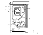
- FIG. 10 is a schematic view showing a state in which the side back plate 2 according to the present embodiment is removed. As shown in FIG. 10, the side back plate 2 has a removable configuration and is removed at the time of service.
- the liquid closing valve 6 and the gas closing valve 7 are not fixed to the side back plate 2, the liquid closing valve 6 and the gas closing valve 7 do not need to be removed from the refrigerant pipe 19 inside the outdoor unit 50. It can be attached and detached. When the side back plate 2 is removed, the side surface and the lower part of the back surface of the machine room 10 are opened. Therefore, it is easy to access the machine room 10, visibility to the inside of the machine room 10 is ensured, and workability such as parts replacement is improved.
- the thermistor detection unit 33 is arranged in the machine room 10.
- the thermistor detection unit 33 is attached to, for example, the heat transfer tube 14a of the outdoor heat exchanger 14.
- the thermistor detection unit 33 is connected to the electrical component unit 20 via the lead wire 24.
- the liquid closing valve 6, and the gas closing valve 7 are arranged in the left-right direction, the height of the back plate 3 is reduced and the second portion of the side back plate 2 is provided. Since the height of 202 can be increased, the opening area can be increased.
- FIG. 11 is a view of the machine room 10 according to the present embodiment as viewed from the right side.
- the right end portion 101 of the front plate 1 extends in a flange shape in a direction perpendicular to the front plate 1.
- a slit 35 extending in the vertical direction is formed at the right end portion 101. The slit 35 is formed so that the side back plate 2 can be attached and detached.
- the side back plate 2 is removed from the outdoor unit 50, and the machine room 10 is opened.
- a thermistor detection unit 33, an expansion valve control coil 23, and a four-way valve control coil 22 are arranged as service target parts whose service response is relatively light.
- the lead wire 24 is not shown.
- the lead wire 24 is removed from the lead wire hook 25a arranged on the right side surface of the board support member 25.
- the lead wire 24 extending from the four-way valve control coil 22 is removed from the electrical component unit 20, and the screw 22a fixing the four-way valve control coil 22 is removed. This makes it possible to provide services such as replacement of the four-way valve control coil 22.
- the lead wire 24 is removed from the lead wire hook 25a arranged on the right side surface of the substrate support member 25.
- the lead wire 24 extending from the expansion valve control coil 23 is removed from the electrical component unit 20, and the expansion valve control coil 23 is removed from the expansion valve 27 main body so as to be pulled out. This makes it possible to provide services such as replacement of the expansion valve control coil 23.
- the lead wire 24 is removed from the lead wire hook 25a arranged on the right side surface of the board support member 25.
- the lead wire 24 extending from the thermistor detection unit 33 is removed from the electrical component unit 20, and the thermistor detection unit 33 is removed from the holder. This makes it possible to provide services such as replacement of the thermistor detection unit 33.
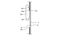
- FIG. 12 is a schematic view of the hook 203 provided on the side back plate 2 according to the present embodiment. As shown in FIG. 12, a hook 203 is provided on the side end portion 2a of the side back plate 2. The hook 203 is for attaching and detaching the side back plate 2 to the front plate 1.
- the hook 203 has a base end 203a protruding from the side end portion 2a of the side back plate 2 and a tip end 203b extending in a direction away from the base end 203a.
- an upper groove 204 is formed so that the gap 204b between the base end 203a of the hook 203 and the side end portion 2a of the side back plate 2 decreases downward.
- the lowermost portion of the upper groove 204 is a root portion 204a in which the gap 204b between the base end 203a of the hook 203 and the side end portion 2a of the side back plate 2 is constant.
- a lower groove 205 is formed so that the gap 205a between the base end 203a of the hook 203 and the side end portion 2a of the side back plate 2 decreases upward. ing.
- FIG. 13 is a schematic view showing a state in which the hook 203 according to the present embodiment is attached to the front plate 1.
- the hook 203 has a shape protruding in a direction perpendicular to the surface of the side back plate 2.
- the hook 203 provided at the side end portion 2a of the side back plate 2 is inserted into the slit 35 formed in the front plate 1.
- the gap 204b of the upper groove 204 of the hook 203 is configured to decrease downward, the upper edge portion 35a of the slit 35 is easily guided to the upper groove 204 of the hook 203.
- the gap 204b at the base portion 204a of the hook 203 is constant and is equivalent to the plate thickness of the front plate 1. The lower edge of the slit 35 is pushed and held in the root portion 204a of the hook 203.
- the side back plate 2 may have another hook in addition to the hook 203.
- the position where the other hook is placed is not limited to the above.
- the slit for attaching the other hook may be provided at a position corresponding to the other hook.
- a second hook may be formed on the side end portion 2a of the second portion 202 of the side back plate 2.
- the second hook may have the same shape as the hook 203, and may be formed so as to project from the side end portion 2a of the second portion 202 along the surface direction of the side end portion 2a.
- the second hook may be configured to form a second slit in the heat exchange support plate 32 and insert it into the second slit. The second hook allows the side back plate 2 to be detachably attached to the heat exchange support plate 32.
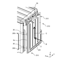
- FIG. 14 is a diagram illustrating an attachment procedure of the side back plate 2 according to the present embodiment.
- FIG. 15 is a diagram illustrating the operation of the hook 203 according to the present embodiment.
- the side back plate 2 is moved in the direction of the arrow B in FIG. 14, and the hook 203 is inserted into the slit 35.
- the direction of the arrow B in FIG. 14 is the same as the direction in which the hook 203 provided on the side end portion 2a of the first portion 201 of the side back plate 2 protrudes from the side end portion 2a of the first portion 201. Further, the direction of the arrow B in FIG. 14 is perpendicular to the opening surface of the slit 35. As a result, the hook 203 is smoothly inserted into the slit 35 that opens in the surface of the hook 203 in the direction intersecting the protruding direction.
- the side back plate 2 is slid in the direction of the arrow C in FIG. 14 to move by the stroke amount d, and the side back plate 2 is attached to the front plate 1.
- the upper edge portion 35a of the slit 35 is inserted into the gap 204b of the upper groove 204 of the hook 203. Since the gap 204b of the upper groove 204 of the hook 203 is configured to decrease downward, the upper edge portion 35a of the slit 35 is easily guided to the upper groove 204, and the insertability of the hook 203 is improved.
- the root portion 204a of the hook 203 reaches the upper edge portion 35a of the slit 35. Since the gap 204b of the root portion 204a is equivalent to the thickness of the front plate 1 on which the slit 35 is formed, the hook 203 abuts on the slit 35 to prevent the side back plate 2 from moving upward.
- the side back plate 2 is temporarily fixed to the top plate 4, the bottom plate 13, the back plate 3, and the heat exchange support plate 32 by the mounting screws 213. This completes the mounting of the side back plate 2.
- the mounting screws 213 are first removed. Since the side back plate 2 is temporarily fixed to the front plate 1 in a state where the mounting screws 213 are removed, the side back plate 2 is suppressed from falling.
- the side back plate 2 When removing the side back plate 2, if the temporary fixing is released with the mounting screws 213 of the side back plate 2 removed, the side back plate 2 may fall. As shown in FIG. 15 (3), when the side back plate 2 falls and the side back plate 2 moves downward by a stroke amount d or more, the lower groove 205 of the hook 203 hits the lower edge portion 35b of the slit 35. Contact. As a result, the downward movement of the side back plate 2 is restricted, and the side back plate 2 is prevented from falling.
- the gap 205a of the lower groove 205 of the hook 203 is configured to decrease upward, and the lower edge portion 35b of the slit 35 is easily guided by the lower groove 205, so that the side back plate 2 is surely prevented from falling. Can be done.
- the outdoor unit 50 is installed in a space installed on the premise of installing an air conditioner integrated inside and outside or a separate type outdoor unit, which is called a window type, unlike a general veranda or balcony.
- a fall prevention wall is not arranged on the outer periphery of the building.
- the hook 203 can secure the insertability of the hook 203 by increasing the total length of the slit 35 with respect to the total length of the hook 203. Further, if the difference between the total length of the slit 35 and the total length of the hook 203 is suppressed to about 3 mm or less, the hook 203 is prevented from falling off from the slit 35, which is further preferable.
- FIG. 16 is a schematic view of a cross section along a plane extending in the Z direction through the DD line of FIG.
- an upper step portion 211 is formed on the upper portion of the side back plate 2.
- the upper step portion 211 of the side back plate 2 is a recess toward the inside of the housing 55.
- the upper step portion 211 of the side back plate 2 overlaps with the flange-shaped outer peripheral edge portion 4a of the top plate 4, whereby rainwater, small animals, and external fire can enter the inside of the housing 55. It is preventing.
- the overlap amount 2c in which the upper step portion 211 and the outer peripheral edge portion 4a overlap is smaller than the stroke amount d that moves the side back plate 2 when the side back plate 2 is mounted, that is, the depth of the upper groove 204. As a result, the side back plate 2 can be attached and detached while the top plate 4 is attached.
- the back plate 3 may be divided into two parts, an upper part and a lower part.
- the upper portion may be configured to be detachable with the terminal block fixing plate 30 of the terminal block 29 attached
- the lower portion may be configured to have the liquid closing valve 6 and the gas closing valve 7 attached.
- the back plate 3 When the back plate 3 is divided into two, it is possible to prevent foreign matter from entering the machine room 10 by overlapping the upper part and the lower part. Further, when the back plate 3 is divided into two, it is preferable to attach a water blocking part between the upper part and the lower part to prevent water from entering.
- FIG. 17 is a diagram illustrating a back plate 3 according to a modified example.
- the terminal block fixing plate 30 fixed to the service window 3c is removable. With the terminal block fixing plate 30 removed, the four-way valve control coil 22 can be visually recognized from the service window 3c. Since the terminal block fixing plate 30 is removable, if the terminal block fixing plate 30 is temporarily removed, a window for visually recognizing the inside of the machine room 10 together with the LED viewing window 3b located adjacent to the terminal block fixing plate 30. Can be used as.
- the housing 55 is fixed to the liquid closing valve 6 to which the end of the refrigerant pipe 19 is connected, the gas closing valve 7, and the terminal block 29.
- the back plate 3 is included, and the side back plate 2 detachably attached to the front plate 1 is included. Therefore, the side back plate 2 can be removed and the inside of the housing 55 can be opened to the outside without removing the liquid closing valve 6, the gas closing valve 7, and the terminal block 29, so that workability in maintenance of the outdoor unit 50 can be achieved. Is improved.
- the side back plate 2 is attached by inserting the hook 203 into the slit 35 formed in the front plate 1, it is easy to attach the side back plate 2 and to position the side back plate 2.
- the lower groove 205 is formed on the hook 203, when the mounting screw 213 of the side back plate 2 is removed and lowered, the lower groove 205 of the hook 203 comes into contact with the lower edge portion 35b of the slit 35 and is on the side. The downward movement of the back plate 2 is restricted. Therefore, it is possible to prevent the side back plate 2 from falling.
- the upper groove 204 of the hook 203 has a configuration in which the gap 204b is reduced, the upper groove 204 of the hook 203 is easily guided to the upper edge portion 35a of the slit 35, and the side back plate 2 is positioned at a predetermined position. Is easy.
- the upper groove 204 of the hook 203 has the root portion 204a, when the side back plate 2 is attached, the lower edge portion 35b of the slit 35 is sandwiched between the root portions 204a and the side back plate 2 is temporarily fixed. Can be done. Therefore, the work of attaching the side back plate 2 can be performed safely and easily.
- the hook 203 and the slit 35 are disengaged without removing the top plate 4. , The side back plate 2 can be removed.
- the machine room 10 is opened and the four-way valve 28, the expansion valve 27, and the thermistor detection unit 33 are exposed, so that the work at the time of service becomes easy.
Landscapes
- Engineering & Computer Science (AREA)
- Chemical & Material Sciences (AREA)
- Combustion & Propulsion (AREA)
- Mechanical Engineering (AREA)
- General Engineering & Computer Science (AREA)
- Other Air-Conditioning Systems (AREA)
Priority Applications (3)
| Application Number | Priority Date | Filing Date | Title |
|---|---|---|---|
| JP2022548268A JP7796656B2 (ja) | 2020-09-08 | 2020-09-08 | 室外機 |
| CN202080102773.4A CN115917217B (zh) | 2020-09-08 | 2020-09-08 | 室外机 |
| PCT/JP2020/033928 WO2022054128A1 (ja) | 2020-09-08 | 2020-09-08 | 室外機 |
Applications Claiming Priority (1)
| Application Number | Priority Date | Filing Date | Title |
|---|---|---|---|
| PCT/JP2020/033928 WO2022054128A1 (ja) | 2020-09-08 | 2020-09-08 | 室外機 |
Publications (1)
| Publication Number | Publication Date |
|---|---|
| WO2022054128A1 true WO2022054128A1 (ja) | 2022-03-17 |
Family
ID=80631398
Family Applications (1)
| Application Number | Title | Priority Date | Filing Date |
|---|---|---|---|
| PCT/JP2020/033928 Ceased WO2022054128A1 (ja) | 2020-09-08 | 2020-09-08 | 室外機 |
Country Status (3)
| Country | Link |
|---|---|
| JP (1) | JP7796656B2 (https=) |
| CN (1) | CN115917217B (https=) |
| WO (1) | WO2022054128A1 (https=) |
Cited By (1)
| Publication number | Priority date | Publication date | Assignee | Title |
|---|---|---|---|---|
| EP4538604A4 (en) * | 2022-07-08 | 2025-09-17 | Daikin Ind Ltd | OUTDOOR UNIT |
Citations (2)
| Publication number | Priority date | Publication date | Assignee | Title |
|---|---|---|---|---|
| JP2002267209A (ja) * | 2001-03-09 | 2002-09-18 | Fujitsu General Ltd | スプリット型エアコンの室外機 |
| JP2010175195A (ja) * | 2009-01-30 | 2010-08-12 | Daikin Ind Ltd | 冷凍装置の室外ユニット |
Family Cites Families (7)
| Publication number | Priority date | Publication date | Assignee | Title |
|---|---|---|---|---|
| JP4721943B2 (ja) | 2006-04-04 | 2011-07-13 | 三洋電機株式会社 | 空気調和装置の室外機 |
| JP2009097726A (ja) * | 2007-10-12 | 2009-05-07 | Daikin Ind Ltd | 冷凍装置の室外ユニット |
| JP2010145063A (ja) * | 2008-12-22 | 2010-07-01 | Panasonic Corp | 空気調和装置の室外機 |
| CN103732993B (zh) * | 2011-07-07 | 2016-08-17 | 东芝开利株式会社 | 制冷循环装置的室外单元 |
| EP3059509B1 (en) * | 2014-12-26 | 2019-05-08 | Mitsubishi Electric Corporation | Outdoor unit |
| JP6305619B2 (ja) | 2015-02-17 | 2018-04-04 | 三菱電機株式会社 | 室外機 |
| WO2019159360A1 (ja) * | 2018-02-19 | 2019-08-22 | 三菱電機株式会社 | 空気調和機の室外機 |
-
2020
- 2020-09-08 WO PCT/JP2020/033928 patent/WO2022054128A1/ja not_active Ceased
- 2020-09-08 CN CN202080102773.4A patent/CN115917217B/zh active Active
- 2020-09-08 JP JP2022548268A patent/JP7796656B2/ja active Active
Patent Citations (2)
| Publication number | Priority date | Publication date | Assignee | Title |
|---|---|---|---|---|
| JP2002267209A (ja) * | 2001-03-09 | 2002-09-18 | Fujitsu General Ltd | スプリット型エアコンの室外機 |
| JP2010175195A (ja) * | 2009-01-30 | 2010-08-12 | Daikin Ind Ltd | 冷凍装置の室外ユニット |
Cited By (1)
| Publication number | Priority date | Publication date | Assignee | Title |
|---|---|---|---|---|
| EP4538604A4 (en) * | 2022-07-08 | 2025-09-17 | Daikin Ind Ltd | OUTDOOR UNIT |
Also Published As
| Publication number | Publication date |
|---|---|
| JP7796656B2 (ja) | 2026-01-09 |
| CN115917217A (zh) | 2023-04-04 |
| CN115917217B (zh) | 2026-03-17 |
| JPWO2022054128A1 (https=) | 2022-03-17 |
Similar Documents
| Publication | Publication Date | Title |
|---|---|---|
| US10753631B2 (en) | Air-conditioner indoor unit | |
| EP3214383A1 (en) | Air conditioner | |
| EP2206978A1 (en) | Outdoor unit for air conditioner | |
| JP5527198B2 (ja) | 空気調和装置の室外機 | |
| US11131479B2 (en) | Air-conditioning apparatus indoor unit | |
| JP5471309B2 (ja) | ダクト型空気調和機 | |
| WO2022054128A1 (ja) | 室外機 | |
| JP5674510B2 (ja) | 熱源ユニット | |
| JP5368223B2 (ja) | 空気調和機の室内機 | |
| JP6075399B2 (ja) | 冷凍装置の熱源ユニット | |
| CN215336670U (zh) | 一种天花机 | |
| JP6882716B2 (ja) | 空気調和機の室外機 | |
| EP4108999B1 (en) | Mobile air conditioner | |
| JP5169684B2 (ja) | 空気調和機 | |
| CN212227241U (zh) | 空调器 | |
| CN212319922U (zh) | 移动空调器 | |
| HK40089991A (zh) | 室外机 | |
| JP6984162B2 (ja) | 空気調和機の室外機 | |
| JP2010078220A (ja) | 床置型室内機 | |
| CN222634671U (zh) | 一种空调器 | |
| CN223191722U (zh) | 一种空调器 | |
| JP5232667B2 (ja) | 天井埋込型空気調和装置 | |
| CN120868513A (zh) | 一种空调器 | |
| CN120368507A (zh) | 电气箱和风管机 | |
| EP2565544A2 (en) | Air conditioner |
Legal Events
| Date | Code | Title | Description |
|---|---|---|---|
| 121 | Ep: the epo has been informed by wipo that ep was designated in this application |
Ref document number: 20953196 Country of ref document: EP Kind code of ref document: A1 |
|
| ENP | Entry into the national phase |
Ref document number: 2022548268 Country of ref document: JP Kind code of ref document: A |
|
| NENP | Non-entry into the national phase |
Ref country code: DE |
|
| 122 | Ep: pct application non-entry in european phase |
Ref document number: 20953196 Country of ref document: EP Kind code of ref document: A1 |