WO2022050397A1 - 水の電解装置及びそれを用いた水の電解方法 - Google Patents
水の電解装置及びそれを用いた水の電解方法 Download PDFInfo
- Publication number
- WO2022050397A1 WO2022050397A1 PCT/JP2021/032539 JP2021032539W WO2022050397A1 WO 2022050397 A1 WO2022050397 A1 WO 2022050397A1 JP 2021032539 W JP2021032539 W JP 2021032539W WO 2022050397 A1 WO2022050397 A1 WO 2022050397A1
- Authority
- WO
- WIPO (PCT)
- Prior art keywords
- honeycomb structure
- water
- cathode electrode
- electrode
- porous honeycomb
- Prior art date
- Legal status (The legal status is an assumption and is not a legal conclusion. Google has not performed a legal analysis and makes no representation as to the accuracy of the status listed.)
- Ceased
Links
Images




Classifications
-
- C—CHEMISTRY; METALLURGY
- C25—ELECTROLYTIC OR ELECTROPHORETIC PROCESSES; APPARATUS THEREFOR
- C25B—ELECTROLYTIC OR ELECTROPHORETIC PROCESSES FOR THE PRODUCTION OF COMPOUNDS OR NON-METALS; APPARATUS THEREFOR
- C25B1/00—Electrolytic production of inorganic compounds or non-metals
- C25B1/01—Products
- C25B1/02—Hydrogen or oxygen
- C25B1/04—Hydrogen or oxygen by electrolysis of water
-
- C—CHEMISTRY; METALLURGY
- C25—ELECTROLYTIC OR ELECTROPHORETIC PROCESSES; APPARATUS THEREFOR
- C25B—ELECTROLYTIC OR ELECTROPHORETIC PROCESSES FOR THE PRODUCTION OF COMPOUNDS OR NON-METALS; APPARATUS THEREFOR
- C25B11/00—Electrodes; Manufacture thereof not otherwise provided for
- C25B11/02—Electrodes; Manufacture thereof not otherwise provided for characterised by shape or form
- C25B11/03—Electrodes; Manufacture thereof not otherwise provided for characterised by shape or form perforated or foraminous
-
- C—CHEMISTRY; METALLURGY
- C25—ELECTROLYTIC OR ELECTROPHORETIC PROCESSES; APPARATUS THEREFOR
- C25B—ELECTROLYTIC OR ELECTROPHORETIC PROCESSES FOR THE PRODUCTION OF COMPOUNDS OR NON-METALS; APPARATUS THEREFOR
- C25B15/00—Operating or servicing cells
- C25B15/08—Supplying or removing reactants or electrolytes; Regeneration of electrolytes
-
- C—CHEMISTRY; METALLURGY
- C25—ELECTROLYTIC OR ELECTROPHORETIC PROCESSES; APPARATUS THEREFOR
- C25B—ELECTROLYTIC OR ELECTROPHORETIC PROCESSES FOR THE PRODUCTION OF COMPOUNDS OR NON-METALS; APPARATUS THEREFOR
- C25B9/00—Cells or assemblies of cells; Constructional parts of cells; Assemblies of constructional parts, e.g. electrode-diaphragm assemblies; Process-related cell features
-
- Y—GENERAL TAGGING OF NEW TECHNOLOGICAL DEVELOPMENTS; GENERAL TAGGING OF CROSS-SECTIONAL TECHNOLOGIES SPANNING OVER SEVERAL SECTIONS OF THE IPC; TECHNICAL SUBJECTS COVERED BY FORMER USPC CROSS-REFERENCE ART COLLECTIONS [XRACs] AND DIGESTS
- Y02—TECHNOLOGIES OR APPLICATIONS FOR MITIGATION OR ADAPTATION AGAINST CLIMATE CHANGE
- Y02E—REDUCTION OF GREENHOUSE GAS [GHG] EMISSIONS, RELATED TO ENERGY GENERATION, TRANSMISSION OR DISTRIBUTION
- Y02E60/00—Enabling technologies; Technologies with a potential or indirect contribution to GHG emissions mitigation
- Y02E60/30—Hydrogen technology
- Y02E60/36—Hydrogen production from non-carbon containing sources, e.g. by water electrolysis
Definitions
- the present invention relates to a water electrolyzer and a water electrolysis method using the same.
- hydrogen gas is generated from a cathode electrode by electrolyzing water using an acidic electrolytic solution or an alkaline electrolytic solution.
- technological development for efficiently generating hydrogen gas has been conventionally made.
- the water electrolyzer disclosed in Patent Document 1 has a configuration in which a unit cell constituting the device has an electrolyte membrane / electrode structure sandwiched between an anode-side separator and a cathode-side separator.
- the electrolyte membrane / electrode structure includes a cathode side feeding body in contact with the cathode side separator and an anode side feeding body in contact with the anode side separator, and a large number of electrolyte membranes / electrode structures are provided between the anode side feeding body and the solid polymer electrolyte membrane.
- a protective sheet member having a through hole formed therein is interposed. It is described that, with such a configuration, water is smoothly introduced into the through hole, water is satisfactorily supplied to the electrolyte membrane, and the generated gas can be easily separated.
- Patent Document 1 since the water electrolyzer includes a protective sheet in which a large number of through holes are formed in the electrodes, the water supply capacity from the through holes to the electrolyte membrane is increased, thereby efficiently generating hydrogen gas. It is stated that it can be made to. However, when the current density generated in the contact portion between the electrode and the protective sheet increases due to the electrolysis of water, the following problems occur.
- An object of the present invention is to provide a water electrolyzer capable of efficiently electrolyzing water and a water electrolysis method using the same in order to solve such a problem.
- the present inventors have focused on the analogy of heat and mass transfer, and found that the above problems can be solved by using this. That is, in the present invention, by providing a porous honeycomb structure on the surface of the electrode (cathode electrode) that generates hydrogen, water is forcibly supplied to the reaction electrode surface by the capillary force utilizing the porosity. At the same time, the generated hydrogen (hydrogen bubbles) is discharged from the opening of the honeycomb structure to prevent the electrodes from being covered with the gas phase. It has been found that these effects improve the critical current density of hydrogen generation in the electrolysis of water, and the electrolysis of water can be efficiently performed.
- An electrolytic tank having an anode chamber provided with an anode electrode, a cathode chamber provided with a cathode electrode, and a diaphragm for partitioning the anode chamber and the cathode chamber, and electrolyzing water to produce hydrogen. It is a water electrolyzer equipped with A water electrolyzer in which a porous honeycomb structure is provided on the surface of the cathode electrode.
- the porous honeycomb structure is a laminated structure including a first porous honeycomb structure on the cathode electrode side and a second porous honeycomb structure on the opposite side of the cathode electrode.
- the water electrolyzer according to (1) wherein the second porous honeycomb structure has a higher water transmittance than the first porous honeycomb structure.
- the second porous honeycomb structure is larger than the first porous honeycomb structure by making the opening radius larger than the opening radius of the first porous honeycomb structure.
- Water electrolyzer with increased water permeability (4) The water electrolyzer according to any one of (1) to (3), wherein the water is alkaline water. (5) A water electrolysis method for producing hydrogen by electrolyzing water using the water electrolyzer according to any one of (1) to (4).
- FIG. 1 is a schematic view of a water electrolyzer 10 according to an embodiment of the present invention.
- the water electrolyzer 10 has an anode chamber 12 provided with an anode electrode 14, a cathode chamber 11 provided with a cathode electrode 13, and a diaphragm 15 for partitioning the anode chamber 12 and the cathode chamber 11. Further, the water electrolyzer 10 includes an electrolytic cell 18 that electrolyzes the water 16 to produce hydrogen.
- the cathode electrode 13 can be made of iron, iron-rare earths, iron-nickel alloy, nickel, or the like.
- the anode electrode 14 includes nickel, nickel-based alloy, iron, nickel-coated iron, ion plate nickel (Ag + , Li + , He + , Kr + ), nickel cobalt oxide, cobalt oxide, lanthanum-doped cobalt oxide, and lanthanum strontium cobalt.
- the diaphragm 15 is composed of asbestos, polymer-reinforced asbestos, PTFE-bound potassium titanate, PTFE-bound zirconia, polysulfone-bound polyantimonic acid / antimony oxide, sintered nickel, ceramics / nickel oxide-coated nickel, polysulfone, and the like. Can be done.
- examples of the water (electrolyzed liquid) to be electrolyzed include alkaline water and acidic water.
- alkaline water a sodium hydroxide aqueous solution, a potassium hydroxide aqueous solution, or the like can be used, and more specifically, a 20 to 30% by mass potassium hydroxide aqueous solution can be used.
- acidic water hydrochloric acid, sulfuric acid, perchloric acid and the like can be used, and it is particularly preferable to use 1N perchloric acid because the corrosion resistance of the apparatus is good.
- the water electrolyzer 10 is provided with a porous honeycomb structure 17 on the surface of the cathode electrode 13.
- the honeycomb structure 17 is not particularly limited, but may be physically pressed and fixed by a wire or the like, or may be attached to the surface of the cathode electrode 13 with an adhesive that can withstand strong alkali.
- the structure of the honeycomb structure 17 can be appropriately designed according to the desired limit current density for hydrogen generation.
- FIG. 2 shows a schematic plan view of the honeycomb structure 17.
- the honeycomb structure 17 has a partition wall 27 that partitions the plurality of openings 28.
- the material of the honeycomb structure 17 is not particularly limited as long as it is porous, but it can be formed of, for example, metal or ceramics.
- the porous metal constituting the honeycomb structure 17 include iron, iron-rare earth, iron-nickel alloy, nickel and the like.
- the ceramics constituting the honeycomb structure 17 include oxide-based ceramics such as alumina, mullite, zirconia and cordierite, and non-oxide ceramics such as silicon carbide, silicon nitride and aluminum nitride.
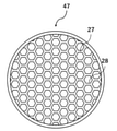
- the planar shape of the honeycomb structure 17 is not particularly limited, but it may have a rectangular plane as a whole as shown in FIG. 2 or a circular plane as a whole as shown in FIG. , Other polygonal or elliptical planes.
- the shape of the cross section of the opening 28 of the honeycomb structure 17 perpendicular to the thickness direction of the honeycomb structure 17 is not particularly limited, but is circular, elliptical, triangular, quadrangular, or more polygonal, or any of these. The combination can be mentioned.
- the thickness of the honeycomb structure 17 is preferably 0.1 mm or more.
- the liquid impregnated inside the honeycomb structure is electrolyzed while the coalesced large bubbles stay on the honeycomb structure, and the liquid is less likely to wither. Can be done.
- the upper limit of the thickness of the honeycomb structure 17 is not particularly limited, and the honeycomb structure 17 can be appropriately designed according to the desired space saving of the apparatus.
- the radius of the opening 28 of the honeycomb structure 17 is preferably 500 to 2000 ⁇ m. If the radius of the opening 28 of the honeycomb structure 17 is less than 500 ⁇ m, the pressure loss when the generated gas phase passes increases. When the radius of the opening 28 of the honeycomb structure 17 is more than 2000 ⁇ m, the area where the honeycomb structure contacts the electrodes becomes small when the wall thickness is constant.
- the "radius of an opening (also referred to as an opening radius)" of the present invention indicates the radius of a circumscribed circle in various opening shapes.
- the porosity of the partition wall 27 of the honeycomb structure 17 is preferably 10 to 80%. When the porosity of the partition wall 27 is less than 10%, the transmittance becomes small and the amount of water that can be supplied by the capillary force becomes small. When the porosity of the partition wall 27 is more than 80%, the strength of the honeycomb structure is weakened.
- the porosity of the partition wall 27 is a value measured by a mercury porosimeter.
- the average pore diameter of the partition wall 27 of the honeycomb structure 17 is preferably 0.1 to 100 ⁇ m. When the average pore diameter of the partition wall 27 is less than 0.1 ⁇ m, the porosity is also small and the transmittance is generally small. If the average pore diameter of the partition wall 27 is more than 100 ⁇ m, the capillary force becomes extremely small.
- the average pore diameter of the partition wall 27 is a value measured by a mercury porosimeter.
- the honeycomb structure 17 is not particularly limited as long as it is provided on the surface of the cathode electrode 13, but in the example shown in FIG. 1, the honeycomb structure 17 is provided on two surfaces of the rectangular parallelepiped cathode electrode 13.
- the honeycomb structure 17 may be provided on one surface of the cathode electrode 13 of a rectangular parallelepiped, three surfaces, or all four surfaces. Further, even when the cathode electrode 13 is not a rectangular parallelepiped, the honeycomb structure 17 can be provided in a desired surface region.
- the coverage of the honeycomb structure 17 on the surface of the cathode electrode 13 is preferably 50% or more. When the coverage of the honeycomb structure 17 on the surface of the cathode electrode 13 is 50% or more, the critical current density of hydrogen generation in the electrolysis of water is further improved.
- the coverage of the honeycomb structure 17 on the surface of the cathode electrode 13 is more preferably 50% or more.
- the coverage of the honeycomb structure 17 on the surface of the cathode electrode 13 can be appropriately controlled by the size, shape, number of installations, etc. of the honeycomb structure 17 with respect to the size of the surface of the cathode electrode 13.
- the honeycomb structure 17 may constitute not only the surface of the cathode electrode 13 but also the entire surface including the surface of the cathode electrode 13. With such a configuration, it is not necessary to consider how to install the honeycomb structure.
- FIG. 4 is an enlarged schematic view of the vicinity of the surface of the cathode electrode 13 of the water electrolyzer 10.
- hydrogen gas lumps may be formed on the surface of the cathode electrode.
- the volume of this hydrogen gas mass increases with time, and eventually cuts off from the surface of the cathode electrode.
- a liquid film having a finite thickness (generally referred to as a macro liquid film) exists between the hydrogen gas mass and the surface of the cathode electrode (that is, the bottom of the hydrogen gas mass).
- the honeycomb structure 17 provided on the surface of the cathode electrode 13 is a porous partition wall when hydrogen gas is generated on the surface of the cathode electrode 13. Water is supplied to the contact portion 23 with the surface of the cathode electrode 13 by the capillary phenomenon caused by 27 (water supply direction 22).
- the hydrogen gas generated on the surface of the cathode electrode 13 is discharged from the contact portion 23 through the opening 28 of the honeycomb structure 17 (hydrogen gas discharge direction 21). That is, the porous partition wall 27 of the honeycomb structure 17 functions as a water supply unit for supplying water to the contact portion 23 with the surface of the cathode electrode 13, and the opening 28 of the honeycomb structure 17 is the cathode electrode 13. It functions as a hydrogen gas discharging part that discharges the hydrogen gas generated by the contact part 23 with the surface. In this way, by supplying water and discharging hydrogen gas using separate paths, the hydrogen gas covers the contact portion 23 on the surface of the cathode electrode 13, and the problem that the critical current density is limited occurs. Can be suppressed.
- the porosity is utilized by providing the porous honeycomb structure 17 on the surface of the electrode (cathode electrode 13) for generating hydrogen. While forcibly supplying water to the reaction electrode surface by the capillary force, the generated hydrogen (hydrogen bubbles) is discharged from the opening 28 of the honeycomb structure 17 so that the electrode (cathode electrode 13) is covered with the gas phase. Suppress. Due to these effects, the critical current density of hydrogen generation in the electrolysis of water is improved, and the electrolysis of water can be efficiently performed. Further, according to such a configuration, in the electrolysis of water, the current density can be increased at a low voltage, and the area of the electrode can be reduced.
- a gap region is formed in the contact portion between the honeycomb structure 17 and the surface of the cathode electrode 13.
- the hydrogen gas generated at the bottom surface of the porous partition wall 27 of the honeycomb structure 17 travels along the bottom surface of the partition wall 27, exits to the opening 28 of the honeycomb structure 17, and is discharged from the opening 28.
- the gap region is the hydrogen gas generated on the bottom surface of the porous partition wall 27 of the honeycomb structure 17. It becomes a passage, the discharge of hydrogen gas is promoted, and the critical current density is improved.
- the surface of the contact portion between the honeycomb structure 17 and the surface of the cathode electrode 13 may be intentionally processed into a rough surface.
- the gap region required for discharging such hydrogen gas has a thickness of 5 to 50 ⁇ m.
- the water electrolyzer 20 shown in FIG. 5 has a first porous honeycomb structure 17 on the cathode electrode 13 side and a second porous structure on the opposite side of the cathode electrode 13. It is a laminated structure including a quality honeycomb structure 37, and the second honeycomb structure 37 has a higher water permeability than the first honeycomb structure 17.
- the second honeycomb structure 37 can have the same configuration as that of the first honeycomb structure 17 except that the transmittance is higher than that of the first honeycomb structure 17.
- the second honeycomb structure 37 may be formed in the same shape and size as the first honeycomb structure 17, or may be formed in a different shape and size. Further, the second honeycomb structure 37 may be formed of the same material as the first honeycomb structure 17, or may be formed of a different material.
- the second honeycomb structure 37 makes the opening radius larger than the opening radius of the first honeycomb structure 17 so that the working fluid can easily pass through, and the water permeates more than the first honeycomb structure 17. The rate may be increased.
- the second honeycomb structure 37 has an opening functioning as a hydrogen gas discharging portion for discharging the hydrogen gas from the first honeycomb structure 17, and a porous partition wall. However, it functions as a water supply unit that forcibly supplies water to the first honeycomb structure 17 due to the capillary phenomenon.
- the second honeycomb structure 37 has a higher permeability than the first honeycomb structure 17 and has a function of holding the liquid, and while the coalesced bubbles stay on the surface of the second honeycomb structure 37. Also, it functions so that the liquid is promptly supplied to the first honeycomb structure 17. Due to these effects, the critical current density of hydrogen generation in the electrolysis of water is further improved, and the electrolysis of water can be performed more efficiently.
- the first honeycomb structure 17 supplies water to the contact portion by capillarity when hydrogen gas is generated in the partition wall 27, but considering the limiting mechanism of water supply by capillary force, the length of the capillaries (that is, that is). , The thickness of the first honeycomb structure 17) can be higher in its limit, that is, the "limit current density".
- the thickness of the first honeycomb structure 17 should be thin from the limit mechanism of liquid supply by capillary force (capillary limit mechanism), but if it is too thin and is about the same as the thickness of the macro liquid film, the first Liquid withering tends to occur in the vicinity of the contact portion of the honeycomb structure 17 of No. 1, and the critical current density becomes small.
- the thickness of the first honeycomb structure 17 provided in the contact portion 23 with the cathode electrode 13 should be thin from the viewpoint of the capillary limit mechanism, but if it is thinner than the thickness of the macro liquid film, the first honeycomb structure 17 should be thin. Liquid withering tends to occur inside the structure 17, and there may be a problem that the critical current density becomes small. Therefore, on the opposite side of the first honeycomb structure 17 provided in the contact portion 23 with the cathode electrode 13 to the cathode electrode 13, a second honeycomb structure 37 having a higher transmittance than the first honeycomb structure 17 is provided.
- the second honeycomb structure 37 that supplies abundant liquid toward the first honeycomb structure 17 is provided between the first honeycomb structure 17 and the hydrogen gas mass on the surface thereof. Since it exists, even if the thickness of the first honeycomb structure 17 is reduced, the occurrence of liquid withering can be suppressed and the critical current density can be prevented from becoming small. Further, since it is preferable that the liquid supply amount of the second honeycomb structure 37 is large, it is preferable to increase the thickness of the second honeycomb structure 37 as well. Specifically, for example, when the thickness of the first honeycomb structure 17 is reduced to about 100 ⁇ m, the thickness of the second honeycomb structure 37 is preferably about 1 to 2 mm or more.
- the porous honeycomb structure does not have to be completely divided into two layers as described above, and as shown in FIG. 6, the pore distribution inside the porous honeycomb structure is inclined. It may be. By inclining the pore distribution inside the porous honeycomb structure in this way, it becomes easier to transfer the liquid, and the electrolytic capacity of the water electrolyzer is further improved.
- the inclination of the pore distribution indicates a state in which the pores 29 inside the porous honeycomb structure decrease as they approach the contact portion 23 with the cathode electrode 13.
- the laminated structure of the honeycomb structure is not limited to the one composed of the first honeycomb structure 17 and the second honeycomb structure 37, and is opposite to the cathode electrode 13 of the second honeycomb structure 37.
- a third honeycomb structure may be further provided on the side to form a three-layer laminated structure as a whole.
- the laminated structure of the honeycomb structure may be configured by laminating a plurality of honeycomb structures on the opposite side of the cathode electrode 13 of the second honeycomb structure 37 to form a total of four or more layers.
- an electrode that generates hydrogen by electrolyzing water (electrolyte solution) using the above-mentioned water electrolysis device 10 or water electrolysis device 20.
- water is forcibly supplied to the reaction electrode surface by the capillary force utilizing the porosity, and the generated hydrogen (hydrogen bubbles) is generated in the honeycomb structure. It is discharged from the opening to prevent the electrode (cathode electrode) from being covered with the gas phase. Due to these effects, the critical current density of hydrogen generation in the electrolysis of water is improved, and the electrolysis of water can be efficiently performed.
- the alkaline water was an aqueous potassium hydroxide solution, having a concentration of 10 w / v% (about 1.785 mol / L) and a pH theoretically calculated value of 14.25.
- a porous honeycomb structure having a coverage of 50% with respect to the electrode area of the portion of the cathode electrode immersed in alkaline water is physically formed by a stainless steel wire having a diameter of 0.3 mm. It was pressed and fixed.
- the honeycomb structure is composed of a composite material of CaO / Al 2 O 3 , quartz glass (SiO 2 ) and TiO 2 and has the shape shown in FIG.
- test example invention example in which the porous honeycomb structure is provided on the surface of the cathode electrode is not in the limit state in the test, and the limit current density of hydrogen generation in the electrolysis of water is improved. It can be seen that the electrolysis of water can be performed efficiently.
Landscapes
- Chemical & Material Sciences (AREA)
- Engineering & Computer Science (AREA)
- Chemical Kinetics & Catalysis (AREA)
- Electrochemistry (AREA)
- Materials Engineering (AREA)
- Metallurgy (AREA)
- Organic Chemistry (AREA)
- Inorganic Chemistry (AREA)
- Electrolytic Production Of Non-Metals, Compounds, Apparatuses Therefor (AREA)
- Electrodes For Compound Or Non-Metal Manufacture (AREA)
Abstract
水の電気分解を効率良く行うことが可能な水の電解装置及びそれを用いた水の電解方法を提供する。アノード電極を設けたアノード室と、カソード電極を設けたカソード室と、アノード室及びカソード室を区画する隔膜とを有し、水を電気分解して水素を製造する電解槽を備えた水の電解装置であって、カソード電極の表面に、多孔質のハニカム構造体が設けられている、水の電解装置。
Description
本発明は、水の電解装置及びそれを用いた水の電解方法に関するものである。
水素社会到来のためには、安価で環境に優しい水素生成プロセスが必要である。そのためには、水の電解技術のブレークスルー、すなわち低い電圧で効率よく大量の水素を生成できる技術が待ち望まれている。
一般に、水の電解装置においては、酸性の電解液またはアルカリ性の電解液を用いて水を電気分解することにより、カソード電極から水素ガスを発生させる。このような水の電解装置において、従来、効率良く水素ガスを発生させるための技術開発がなされている。
特許文献1に開示された水の電解装置は、当該装置を構成する単位セルが、電解質膜・電極構造体をアノード側セパレータ及びカソード側セパレータにより挟持された構成を有している。電解質膜・電極構造体は、カソード側セパレータに接するカソード側給電体と、アノード側セパレータに接するアノード側給電体とを備えるとともに、アノード側給電体と固体高分子電解質膜との間には、多数の貫通孔が形成された保護シート部材が介装される。そして、このような構成により、貫通孔内に水が円滑に導入され、電解質膜に対して水を良好に供給するとともに、発生ガスの離脱が容易に遂行可能になると記載されている。
特許文献1には、水の電解装置が、電極に多数の貫通孔が形成された保護シートを備えるため、貫通孔から電解質膜への水の供給力が高まり、それによって効率良く水素ガスを発生させることができると記載されている。しかしながら、水の電気分解によって、電極と保護シートとの間の接触部に生じる電流密度が増大すると以下の問題が生じる。
すなわち、電流密度が増大するにつれて、水素生成量が増加し、接触部が水素ガスに覆われ始める。接触部が完全に水素ガスに覆われて乾燥状態となり、接触部へ水が供給されなくなると、水の電解装置の電解能力は著しく劣化する。従来の水の電解装置では、電解性能の向上を求めると、このような問題に直面してしまい、水の電気分解を効率良く行うことが困難となる。
本発明は、このような問題を解決すべく、水の電気分解を効率良く行うことが可能な水の電解装置及びそれを用いた水の電解方法を提供することを課題とする。
本発明者らは研究を重ねたところ、熱と物質の移動のアナロジーに着目し、これを利用することで上記課題を解決することができることを見出した。すなわち、本発明では、水素を発生させる電極(カソード電極)の表面に、多孔質のハニカム構造体を設けることにより、多孔質性を利用した毛管力で水を強制的に反応電極面に供給しつつ、生成する水素(水素気泡)をハニカム構造体の開口部から排出して電極が気相で覆われることを抑制する。これらの効果によって、水の電気分解における水素生成の限界電流密度が向上し、水の電気分解を効率良く行うことができることを見出した。
上記課題は、以下のように特定される本発明によって解決される。
(1)アノード電極を設けたアノード室と、カソード電極を設けたカソード室と、前記アノード室及び前記カソード室を区画する隔膜とを有し、水を電気分解して水素を製造する電解槽を備えた水の電解装置であって、
前記カソード電極の表面に、多孔質のハニカム構造体が設けられている、水の電解装置。
(2)前記多孔質のハニカム構造体は、前記カソード電極側の第1の多孔質のハニカム構造体と、前記カソード電極と反対側の第2の多孔質のハニカム構造体とを備えた積層構造体であり、
前記第2の多孔質のハニカム構造体は、前記第1の多孔質のハニカム構造体よりも、水の透過率が大きい、(1)の水の電解装置。
(3)前記第2の多孔質のハニカム構造体は、開口部半径を前記第1の多孔質のハニカム構造体の開口部半径より大きくすることで、前記第1の多孔質のハニカム構造体よりも水の透過率を大きくした、(2)の水の電解装置。
(4)前記水がアルカリ水である(1)~(3)のいずれかの水の電解装置。
(5)(1)~(4)のいずれかの水の電解装置を用いて、水を電気分解して水素を製造する、水の電解方法。
(1)アノード電極を設けたアノード室と、カソード電極を設けたカソード室と、前記アノード室及び前記カソード室を区画する隔膜とを有し、水を電気分解して水素を製造する電解槽を備えた水の電解装置であって、
前記カソード電極の表面に、多孔質のハニカム構造体が設けられている、水の電解装置。
(2)前記多孔質のハニカム構造体は、前記カソード電極側の第1の多孔質のハニカム構造体と、前記カソード電極と反対側の第2の多孔質のハニカム構造体とを備えた積層構造体であり、
前記第2の多孔質のハニカム構造体は、前記第1の多孔質のハニカム構造体よりも、水の透過率が大きい、(1)の水の電解装置。
(3)前記第2の多孔質のハニカム構造体は、開口部半径を前記第1の多孔質のハニカム構造体の開口部半径より大きくすることで、前記第1の多孔質のハニカム構造体よりも水の透過率を大きくした、(2)の水の電解装置。
(4)前記水がアルカリ水である(1)~(3)のいずれかの水の電解装置。
(5)(1)~(4)のいずれかの水の電解装置を用いて、水を電気分解して水素を製造する、水の電解方法。
本発明によれば、水の電気分解を効率良く行うことが可能な水の電解装置及びそれを用いた水の電解方法を提供することができる。
以下、図面を参照して本発明の実施形態を詳細に説明する。
<水の電解装置>
図1は、本発明の実施形態に係る水の電解装置10の模式図である。水の電解装置10は、アノード電極14を設けたアノード室12と、カソード電極13を設けたカソード室11と、アノード室12及びカソード室11を区画する隔膜15とを有している。また、水の電解装置10は、水16を電気分解して水素を製造する電解槽18を備えている。
<水の電解装置>
図1は、本発明の実施形態に係る水の電解装置10の模式図である。水の電解装置10は、アノード電極14を設けたアノード室12と、カソード電極13を設けたカソード室11と、アノード室12及びカソード室11を区画する隔膜15とを有している。また、水の電解装置10は、水16を電気分解して水素を製造する電解槽18を備えている。
本発明の実施形態に係る水の電解装置10のカソード電極13、アノード電極14、及び、隔膜15は、水の電解装置に係る技術分野において、それぞれ公知の構成のものを用いることができる。具体的には、カソード電極13は、鉄、鉄-希土類、鉄-ニッケル合金、ニッケル等で構成することができる。アノード電極14は、ニッケル、ニッケル系合金、鉄、ニッケル被覆鉄、イオンプレートニッケル(Ag+、Li+、He+、Kr+)、ニッケルコバルト酸化物、酸化コバルト、ランタンドープ酸化コバルト、ランタンストロンチウムコバルト酸化物、亜鉛コバルト酸化物、貴金属酸化物等で構成することができる。隔膜15は、アスベスト、高分子補強アスベスト、PTFE結着チタン酸カリウム、PTFE結着ジルコニア、ポリスルホン結着ポリアンチモン酸/酸化アンチモン、焼結ニッケル、セラミックス/酸化ニッケル被覆ニッケル、ポリスルホン等で構成することができる。
本発明の実施形態に係る水の電解装置10において、電気分解の対象となる水(電解液)としては、アルカリ水、酸性水等が挙げられる。アルカリ水としては、水酸化ナトリウム水溶液、水酸化カリウム水溶液等を用いることができ、より具体的には、20~30質量%水酸化カリウム水溶液を用いることができる。酸性水としては、塩酸、硫酸、過塩素酸等を用いることができ、特に、1N過塩素酸を用いると、装置の耐食性等が良好となるため好ましい。
水の電解装置10は、カソード電極13の表面に、多孔質のハニカム構造体17が設けられている。ハニカム構造体17は、特に限定されないが、針金などで物理的に押しつけて固定したり、強アルカリに耐えうる接着剤によってカソード電極13の表面に貼り付けられていてもよい。ハニカム構造体17の構造は、水素生成の所望の限界電流密度によって適宜設計することができる。
図2に、ハニカム構造体17の平面模式図を示す。ハニカム構造体17は、複数の開口部28を区画する隔壁27を有している。ハニカム構造体17の材質は、多孔質であれば特に限定されないが、例えば、金属またはセラミックスで形成することができる。ハニカム構造体17を構成する多孔質の金属としては、例えば、鉄、鉄-希土類、鉄-ニッケル合金、ニッケル等が挙げられる。ハニカム構造体17を構成するセラミックスとしては、アルミナ、ムライト、ジルコニア及びコージェライト等の酸化物系セラミックス、炭化珪素、窒化珪素及び窒化アルミ等の非酸化物系セラミックス等を挙げることができる。
ハニカム構造体17の平面形状は特に限定されないが、図2に示すように全体として矩形の平面を有していてもよく、図3に示すように全体として円形の平面を有していてもよく、その他の多角形または楕円形の平面を有していてもよい。
ハニカム構造体17の開口部28の、ハニカム構造体17の厚さ方向に垂直な断面の形状については特に限定されないが、円形、楕円形、三角形、四角形、またはそれ以上の多角形、又はこれらの組み合わせが挙げられる。
ハニカム構造体17の厚さは、0.1mm以上であることが好ましい。ハニカム構造体17の厚さが0.1mm以上であると、合体大気泡がハニカム構造体上に滞留する間にハニカム構造体内部に含浸されている液体が水電解され、液枯れしにくくすることができる。ハニカム構造体17の厚さの上限についても特に限定されず、装置の所望する省スペース化に合わせて適宜設計することができる。
ハニカム構造体17の開口部28の半径は、500~2000μmであることが好ましい。ハニカム構造体17の開口部28の半径が500μm未満であると、発生した気相が通過する際の圧力損失が増大する。ハニカム構造体17の開口部28の半径が2000μm超であると、壁の厚さを一定とするとハニカム構造体が電極に接触する面積が小さくなる。本発明の「開口部の半径(または開口部半径ともいう)」は、種々の開口部形状における外接円の半径を示す。
ハニカム構造体17の隔壁27の気孔率は、10~80%であることが好ましい。隔壁27の気孔率が10%未満であると、透過率が小さくなり、毛管力で供給できる水量が小さくなる。隔壁27の気孔率が80%超であると、ハニカム構造体の強度が弱くなる。隔壁27の気孔率は、水銀ポロシメータにより測定した値である。
ハニカム構造体17の隔壁27の平均細孔径は、0.1~100μmであることが好ましい。隔壁27の平均細孔径が0.1μm未満であると、空隙率も小さくなり一般的に透過率が小さくなる。隔壁27の平均細孔径が100μm超であると、毛管力が極めて小さくなってしまう。隔壁27の平均細孔径は、水銀ポロシメータにより測定した値である。
ハニカム構造体17は、カソード電極13の表面に設けられていれば特に限定されないが、図1に示す例では、ハニカム構造体17が、直方体のカソード電極13の2つの表面に設けられている。ハニカム構造体17は、直方体のカソード電極13の1つの表面、3つの表面または4つの表面全てに設けられていてもよい。また、カソード電極13が直方体でない場合でも、所望の表面領域にハニカム構造体17を設けることができる。
カソード電極13の表面のハニカム構造体17の被覆率は、50%以上であるのが好ましい。カソード電極13の表面のハニカム構造体17の被覆率が50%以上であると、水の電気分解における水素生成の限界電流密度がより向上する。カソード電極13の表面のハニカム構造体17の被覆率は、50%以上であるのがより好ましい。カソード電極13の表面のハニカム構造体17の被覆率は、カソード電極13の表面の大きさに対する、ハニカム構造体17の大きさ、形状、設置個数などで適宜制御することができる。
ハニカム構造体17は、カソード電極13の表面だけでなく、カソード電極13の表面を含む全体を構成していてもよい。このような構成によれば、ハニカム構造体の設置法を考慮する必要が無い。
次に、本発明の実施形態に係る水の電解装置10の作用について詳述する。図4は、水の電解装置10のカソード電極13の表面近傍の拡大模式図である。一般に、水の電解装置において、カソード電極の表面上で水素ガス塊が形成されることがある。この水素ガス塊の体積は時間と共に増大し、やがてカソード電極の表面から切断離脱する。このとき、水素ガス塊とカソード電極の表面との間(すなわち水素ガス塊の底部)には、有限厚さの液膜(一般に、マクロ液膜と呼ばれる)が存在する。このような状況下においては、水素ガス塊がマクロ液膜上に滞留している間に水素ガス塊底部のマクロ液膜が水電解され消耗し尽くすときに液枯れ現象が発生する。このときの電流密度が「限界電流密度」と呼ばれる。これに対し、本発明の実施形態に係る水の電解装置10では、カソード電極13の表面に設けられたハニカム構造体17は、カソード電極13の表面で水素ガスが発生すれば、多孔質の隔壁27による毛細管現象により、カソード電極13の表面との接触部23に水を供給する(水供給方向22)。一方、カソード電極13の表面で生成した水素ガスは、接触部23から、ハニカム構造体17の開口部28を通って排出される(水素ガス排出方向21)。すなわち、ハニカム構造体17の多孔質の隔壁27が、カソード電極13の表面との接触部23に水を供給する水供給部として機能するとともに、ハニカム構造体17の開口部28がカソード電極13の表面との接触部23で生成する水素ガスを排出する水素ガス排出部として機能する。このように、水の供給と水素ガスの排出を別個の経路を用いて行うことにより、水素ガスがカソード電極13の表面の接触部23を覆ってしまい限界電流密度が制限されるという問題の発生を抑制することができる。
このように、本発明の実施形態に係る水の電解装置10では、水素を発生させる電極(カソード電極13)の表面に、多孔質のハニカム構造体17を設けることにより、多孔質性を利用した毛管力で水を強制的に反応電極面に供給しつつ、生成する水素(水素気泡)をハニカム構造体17の開口部28から排出して電極(カソード電極13)が気相で覆われることを抑制する。これらの効果によって、水の電気分解における水素生成の限界電流密度が向上し、水の電気分解を効率良く行うことができる。また、このような構成によれば、水の電気分解において、低い電圧で電流密度を上げることができ、また、電極の面積を小さくすることができるという効果も有する。
また、ハニカム構造体17と、カソード電極13の表面との接触部に隙間領域が形成されているのが好ましい。ハニカム構造体17の多孔質の隔壁27の底面で生じた水素ガスは、隔壁27の底面に沿って進むことでハニカム構造体17の開口部28へ出て、開口部28から排出される。ここで、ハニカム構造体17と、カソード電極13の表面との接触部に隙間領域が形成されていると、当該隙間領域がハニカム構造体17の多孔質の隔壁27の底面で生じた水素ガスの通路となり、水素ガスの排出が促進され、限界電流密度が向上する。当該隙間領域は、ハニカム構造体17と、カソード電極13の表面との接触部表面をあえて粗面に加工してもよい。このような水素ガスの排出に必要な隙間領域は厚さ5~50μmである。
また、本発明の別の実施形態として、図5に示す水の電解装置20は、カソード電極13側の第1の多孔質のハニカム構造体17と、カソード電極13と反対側の第2の多孔質のハニカム構造体37とを備えた積層構造体であり、第2のハニカム構造体37は、第1のハニカム構造体17よりも、水の透過率が大きい。第2のハニカム構造体37は、第1のハニカム構造体17に対し、透過率が大きい以外は、同様の構成とすることができる。
第2のハニカム構造体37は、第1のハニカム構造体17と同じ形状、大きさに形成されていてもよく、異なる形状、大きさに形成されていてもよい。また、第2のハニカム構造体37は、第1のハニカム構造体17と同じ材料により形成されていてもよく、異なる材料により形成されていてもよい。
第2のハニカム構造体37は、開口部半径を第1のハニカム構造体17の開口部半径より大きくすることで、作動流体を通しやすくして、第1のハニカム構造体17よりも水の透過率を大きくしてもよい。
このようなハニカム構造体の積層構造では、第2のハニカム構造体37は、開口部が第1のハニカム構造体17からの水素ガスを排出する水素ガス排出部として機能するとともに、多孔質の隔壁が、毛細管現象により強制的に第1のハニカム構造体17に水を供給する水供給部として機能する。そして、第2のハニカム構造体37は、第1のハニカム構造体17に比べて透過率が大きく、液を保持する機能を有し、第2のハニカム構造体37表面で合体気泡が滞留する間にも、速やかに第1のハニカム構造体17への液の供給が行われるように機能する。これらの効果によって、水の電気分解における水素生成の限界電流密度がより向上し、水の電気分解をより効率良く行うことができる。
以下、より詳細に上述のハニカム構造体の積層構造の作用について説明する。第1のハニカム構造体17は、隔壁27において、水素ガスが発生すれば毛細管現象により接触部に水を供給するが、毛管力による水供給の限界メカニズムを考慮すれば、毛細管の長さ(すなわち、第1のハニカム構造体17の厚さ)は薄いほうがよりその限界、すなわち「限界電流密度」を高くすることができる。第1のハニカム構造体17の厚さは、上述の通り毛管力による液体供給の限界メカニズム(毛管限界メカニズム)から薄いほうがよいが、薄過ぎてマクロ液膜の厚さと同程度であると、第1のハニカム構造体17の接触部近傍で液枯れが生じやすく、限界電流密度が小さくなる。
このように、カソード電極13との接触部23に設ける第1のハニカム構造体17の厚さは、毛管限界メカニズムの観点からは薄いほうがよいが、マクロ液膜の厚さより薄いと第1のハニカム構造体17内部で液枯れが生じやすく、限界電流密度が小さくなるという問題が生じるおそれがある。そこで、カソード電極13との接触部23に設ける第1のハニカム構造体17の、カソード電極13と反対側に、第1のハニカム構造体17よりも透過率が大きい第2のハニカム構造体37を設ける積層構造によれば、第1のハニカム構造体17とその表面の水素ガス塊との間に、第1のハニカム構造体17に向かって液を潤沢に供給する第2のハニカム構造体37が存在するため、第1のハニカム構造体17の厚さを薄くしても、液枯れの発生が抑制され、限界電流密度が小さくなることを防ぐことができる。また、第2のハニカム構造体37の液供給量は多いほど好ましいため、第2のハニカム構造体37の厚さも大きくするのが好ましい。具体的には、例えば、第1のハニカム構造体17の厚さを100μm程度と薄くする場合、第2のハニカム構造体37の厚さは1~2mm以上程度とするのが好ましい。また、多孔質のハニカム構造体は、上述のように完全に二層に別れていなくてもよく、図6に示すように、多孔質のハニカム構造体の内部の細孔分布を傾斜化したものであってもよい。このように、多孔質のハニカム構造体の内部の細孔分布を傾斜化することで、液の受け渡しがより容易となり、水の電解装置の電解能力がより向上する。当該細孔分布の傾斜化とは、多孔質のハニカム構造体の内部の細孔29が、カソード電極13との接触部23に近づくにつれて少なくなっている状態を示す。
また、ハニカム構造体の積層構造は、第1のハニカム構造体17と第2のハニカム構造体37とで構成されたものに限定されず、第2のハニカム構造体37のカソード電極13とは反対側に、さらに第3のハニカム構造体を設けて、全体で三層の積層構造としてもよい。同様に、ハニカム構造体の積層構造は、第2のハニカム構造体37のカソード電極13とは反対側に、複数のハニカム構造体を積層させて全体で四層以上の構成としてもよい。
<水の電解方法>
本発明の実施形態に係る水の電解方法は、上述の水の電解装置10または水の電解装置20を用いて、水(電解液)を電気分解することにより、水素を発生させる電極(カソード電極)の表面に、多孔質のハニカム構造体を設けることにより、多孔質性を利用した毛管力で水を強制的に反応電極面に供給しつつ、生成する水素(水素気泡)をハニカム構造体の開口部から排出して電極(カソード電極)が気相で覆われることを抑制する。これらの効果によって、水の電気分解における水素生成の限界電流密度が向上し、水の電気分解を効率良く行うことができる。
本発明の実施形態に係る水の電解方法は、上述の水の電解装置10または水の電解装置20を用いて、水(電解液)を電気分解することにより、水素を発生させる電極(カソード電極)の表面に、多孔質のハニカム構造体を設けることにより、多孔質性を利用した毛管力で水を強制的に反応電極面に供給しつつ、生成する水素(水素気泡)をハニカム構造体の開口部から排出して電極(カソード電極)が気相で覆われることを抑制する。これらの効果によって、水の電気分解における水素生成の限界電流密度が向上し、水の電気分解を効率良く行うことができる。
以下に本発明を実施例でさらに詳細に説明するが、本発明はこれらに限定されるものではない。
(試験例1)
アルカリ水を投入した電解槽中に、それぞれステンレス板であるアノード電極とカソード電極とを設けた。このとき、カソード電極のアルカリ水への浸漬部の電極面積は、H(高さ)17mm×W(幅)10mm=170mm2とした。アルカリ水は、水酸化カリウム水溶液であり、濃度10w/v%(約1.785mol/L)、PH理論計算値:14.25であった。
次に、カソード電極の表面に、カソード電極のアルカリ水への浸漬部の電極面積に対し、被覆率50%で多孔質のハニカム構造体を、直径0.3mmのステンレス製の針金によって物理的に押しつけ固定した。当該ハニカム構造体は、CaO・Al2O3、石英ガラス(SiO2)及びTiO2の複合材料で構成され、図3に示す形状を有する。当該ハニカム構造体は、30mm径の円形の外径を有し、縦×横=1.3mm×1.3mmの略正方形の複数の開口部と、当該開口部を区画する厚さ0.4mmの隔壁を有する。隔壁の気孔率は25%、隔壁の平均細孔径は、0.13μm、ハニカム構造体の開口率は45%であった。
アルカリ水を投入した電解槽中に、それぞれステンレス板であるアノード電極とカソード電極とを設けた。このとき、カソード電極のアルカリ水への浸漬部の電極面積は、H(高さ)17mm×W(幅)10mm=170mm2とした。アルカリ水は、水酸化カリウム水溶液であり、濃度10w/v%(約1.785mol/L)、PH理論計算値:14.25であった。
次に、カソード電極の表面に、カソード電極のアルカリ水への浸漬部の電極面積に対し、被覆率50%で多孔質のハニカム構造体を、直径0.3mmのステンレス製の針金によって物理的に押しつけ固定した。当該ハニカム構造体は、CaO・Al2O3、石英ガラス(SiO2)及びTiO2の複合材料で構成され、図3に示す形状を有する。当該ハニカム構造体は、30mm径の円形の外径を有し、縦×横=1.3mm×1.3mmの略正方形の複数の開口部と、当該開口部を区画する厚さ0.4mmの隔壁を有する。隔壁の気孔率は25%、隔壁の平均細孔径は、0.13μm、ハニカム構造体の開口率は45%であった。
次に、カソード電極及びアノード電極間に電圧をかけ、定常になるまで約30秒間待機した後、電圧を上昇させながら、電流密度を測定していった。
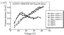
当該測定結果からアルカリ水電解特性曲線を作成し、図7に示す。なお、上記試験は3回行われ、図7の「HPP1」~「HPP3」は、これら3回の、多孔質のハニカム構造体をカソード電極の表面に設けて実施した試験の結果をそれぞれ示す。
当該測定結果からアルカリ水電解特性曲線を作成し、図7に示す。なお、上記試験は3回行われ、図7の「HPP1」~「HPP3」は、これら3回の、多孔質のハニカム構造体をカソード電極の表面に設けて実施した試験の結果をそれぞれ示す。
また、上述の試験において、カソード電極の表面に何も設けず(多孔質のハニカム構造体を設けず)裸面とした以外は、全て同様の条件で水の電気分解を行い、同様の条件にて電圧を上昇させながら、電流密度を測定し、当該測定結果からアルカリ水電解特性曲線を作成した。当該試験は4回行った。図7の「Bare surface1」~「Bare surface4」は、これら4回の、カソード電極の表面を裸面として実施した試験の結果をそれぞれ示す。
(評価結果)
図7に示すアルカリ水電解特性曲線によれば、カソード電極の表面を裸面とした試験例(比較例)である「Bare surface1」~「Bare surface4」は、いずれも電圧上昇につれて、電流密度が初めは上昇するが、途中で頭打ちになる(電流密度の最大値がある)ことがわかる。
これに対し、カソード電極の表面に多孔質のハニカム構造体を設けた試験例(発明例)である「HPP1」~「HPP3」は、電圧上昇と共に電流密度が、途中で頭打ちにならず上昇していくことがわかる。すなわち、カソード電極の表面に多孔質のハニカム構造体を設けた試験例(発明例)は、当該試験においては限界状態になっておらず、水の電気分解における水素生成の限界電流密度が向上し、水の電気分解を効率良く行うことができることがわかる。
図7に示すアルカリ水電解特性曲線によれば、カソード電極の表面を裸面とした試験例(比較例)である「Bare surface1」~「Bare surface4」は、いずれも電圧上昇につれて、電流密度が初めは上昇するが、途中で頭打ちになる(電流密度の最大値がある)ことがわかる。
これに対し、カソード電極の表面に多孔質のハニカム構造体を設けた試験例(発明例)である「HPP1」~「HPP3」は、電圧上昇と共に電流密度が、途中で頭打ちにならず上昇していくことがわかる。すなわち、カソード電極の表面に多孔質のハニカム構造体を設けた試験例(発明例)は、当該試験においては限界状態になっておらず、水の電気分解における水素生成の限界電流密度が向上し、水の電気分解を効率良く行うことができることがわかる。
10、20 水の電解装置
11 カソード室
12 アノード室
13 カソード電極
14 アノード電極
15 隔膜
16 水
17、37、47 ハニカム構造体
21 水素ガス排出方向
22 水供給方向
23 接触部
27 隔壁
28 開口部
29 細孔
11 カソード室
12 アノード室
13 カソード電極
14 アノード電極
15 隔膜
16 水
17、37、47 ハニカム構造体
21 水素ガス排出方向
22 水供給方向
23 接触部
27 隔壁
28 開口部
29 細孔
Claims (5)
- アノード電極を設けたアノード室と、カソード電極を設けたカソード室と、前記アノード室及び前記カソード室を区画する隔膜とを有し、水を電気分解して水素を製造する電解槽を備えた水の電解装置であって、
前記カソード電極の表面に、多孔質のハニカム構造体が設けられている、水の電解装置。 - 前記多孔質のハニカム構造体は、前記カソード電極側の第1の多孔質のハニカム構造体と、前記カソード電極と反対側の第2の多孔質のハニカム構造体とを備えた積層構造体であり、
前記第2の多孔質のハニカム構造体は、前記第1の多孔質のハニカム構造体よりも、水の透過率が大きい、請求項1に記載の水の電解装置。 - 前記第2の多孔質のハニカム構造体は、開口部半径を前記第1の多孔質のハニカム構造体の開口部半径より大きくすることで、前記第1の多孔質のハニカム構造体よりも水の透過率を大きくした、請求項2に記載の水の電解装置。
- 前記水がアルカリ水である請求項1~3のいずれか一項に記載の水の電解装置。
- 請求項1~4のいずれか一項に記載の水の電解装置を用いて、水を電気分解して水素を製造する、水の電解方法。
Applications Claiming Priority (2)
| Application Number | Priority Date | Filing Date | Title |
|---|---|---|---|
| JP2020-149397 | 2020-09-04 | ||
| JP2020149397A JP2022043896A (ja) | 2020-09-04 | 2020-09-04 | 水の電解装置及びそれを用いた水の電解方法 |
Publications (1)
| Publication Number | Publication Date |
|---|---|
| WO2022050397A1 true WO2022050397A1 (ja) | 2022-03-10 |
Family
ID=80491087
Family Applications (1)
| Application Number | Title | Priority Date | Filing Date |
|---|---|---|---|
| PCT/JP2021/032539 Ceased WO2022050397A1 (ja) | 2020-09-04 | 2021-09-03 | 水の電解装置及びそれを用いた水の電解方法 |
Country Status (2)
| Country | Link |
|---|---|
| JP (1) | JP2022043896A (ja) |
| WO (1) | WO2022050397A1 (ja) |
Citations (3)
| Publication number | Priority date | Publication date | Assignee | Title |
|---|---|---|---|---|
| JPH0919621A (ja) * | 1995-07-06 | 1997-01-21 | Matsushita Electric Ind Co Ltd | 脱酸素装置 |
| JPH1036988A (ja) * | 1996-07-24 | 1998-02-10 | Choichi Furuya | 気泡捕集型ガス電極 |
| CN108085715A (zh) * | 2017-12-26 | 2018-05-29 | 郑州日月信息技术有限公司 | 一种电解性能好的新能源发生器阴极板 |
-
2020
- 2020-09-04 JP JP2020149397A patent/JP2022043896A/ja active Pending
-
2021
- 2021-09-03 WO PCT/JP2021/032539 patent/WO2022050397A1/ja not_active Ceased
Patent Citations (3)
| Publication number | Priority date | Publication date | Assignee | Title |
|---|---|---|---|---|
| JPH0919621A (ja) * | 1995-07-06 | 1997-01-21 | Matsushita Electric Ind Co Ltd | 脱酸素装置 |
| JPH1036988A (ja) * | 1996-07-24 | 1998-02-10 | Choichi Furuya | 気泡捕集型ガス電極 |
| CN108085715A (zh) * | 2017-12-26 | 2018-05-29 | 郑州日月信息技术有限公司 | 一种电解性能好的新能源发生器阴极板 |
Also Published As
| Publication number | Publication date |
|---|---|
| JP2022043896A (ja) | 2022-03-16 |
Similar Documents
| Publication | Publication Date | Title |
|---|---|---|
| US5650058A (en) | Electrolytic cell and capillary gap electrode for gas-developing or gas-consuming electrolytic reactions and electrolysis process therefor | |
| US4729932A (en) | Fuel cell with integrated cooling water/static water removal means | |
| US4761348A (en) | Electrolytic cell stack with molten electrolyte migration control | |
| JP3264493B2 (ja) | 水の電解槽用二方向流イオン交換媒質支持体 | |
| NZ202496A (en) | Electrolytic cell electrode:foraminate grid bonded to pips on conductive sheet | |
| JP2005509744A (ja) | ガス拡散電極を備えた電解セル | |
| JPS60163375A (ja) | 液状電解質の電気化学的処理法 | |
| NL2023775B1 (en) | Compact electrochemical stack using corrugated electrodes | |
| JP2018048411A (ja) | オリフィスを有する酸素消費電極を用いるアルカリ金属塩化物の電気分解法 | |
| JP5904854B2 (ja) | 金属空気電池 | |
| ITMI20000150A1 (it) | Cella di elettrolisi con elettrodo a diffusione di gas | |
| US5565082A (en) | Brine electrolysis and electrolytic cell therefor | |
| US20240384424A1 (en) | Construction of an electrochemical cell | |
| KR20220109708A (ko) | 수전해 장치 | |
| JPH08507327A (ja) | 隔膜式電解槽におけるガス生成電解法用電極装置およびその使用 | |
| US5938901A (en) | Liquid permeation-type gas-diffusion electrode | |
| US5087344A (en) | Electrolysis cell for gas-evolving electrolytic processes | |
| JP2022043896A (ja) | 水の電解装置及びそれを用いた水の電解方法 | |
| EP1362133B1 (en) | Electrolysis cell with gas diffusion electrode operating at controlled pressure | |
| US3391028A (en) | Fuel cell and method of producing electricity | |
| EP3626860B1 (en) | Hydrogen production apparatus | |
| JP2005158383A (ja) | レドックス電池 | |
| US4620902A (en) | Electrolysis process using liquid electrolytes and porous electrodes | |
| JP3110555B2 (ja) | イオン交換膜電解槽 | |
| US4714533A (en) | Electrolyser for highly-active tritiated water |
Legal Events
| Date | Code | Title | Description |
|---|---|---|---|
| 121 | Ep: the epo has been informed by wipo that ep was designated in this application |
Ref document number: 21864449 Country of ref document: EP Kind code of ref document: A1 |
|
| NENP | Non-entry into the national phase |
Ref country code: DE |
|
| 122 | Ep: pct application non-entry in european phase |
Ref document number: 21864449 Country of ref document: EP Kind code of ref document: A1 |