WO2022050112A1 - パーツ連結構造及び人形玩具 - Google Patents
パーツ連結構造及び人形玩具 Download PDFInfo
- Publication number
- WO2022050112A1 WO2022050112A1 PCT/JP2021/030819 JP2021030819W WO2022050112A1 WO 2022050112 A1 WO2022050112 A1 WO 2022050112A1 JP 2021030819 W JP2021030819 W JP 2021030819W WO 2022050112 A1 WO2022050112 A1 WO 2022050112A1
- Authority
- WO
- WIPO (PCT)
- Prior art keywords
- movable part
- movable
- guide
- parts
- base part
- Prior art date
- Legal status (The legal status is an assumption and is not a legal conclusion. Google has not performed a legal analysis and makes no representation as to the accuracy of the status listed.)
- Ceased
Links
Images


Classifications
-
- A—HUMAN NECESSITIES
- A63—SPORTS; GAMES; AMUSEMENTS
- A63H—TOYS, e.g. TOPS, DOLLS, HOOPS OR BUILDING BLOCKS
- A63H3/00—Dolls
-
- A—HUMAN NECESSITIES
- A63—SPORTS; GAMES; AMUSEMENTS
- A63H—TOYS, e.g. TOPS, DOLLS, HOOPS OR BUILDING BLOCKS
- A63H13/00—Toy figures with self-moving parts, with or without movement of the toy as a whole
-
- A—HUMAN NECESSITIES
- A63—SPORTS; GAMES; AMUSEMENTS
- A63H—TOYS, e.g. TOPS, DOLLS, HOOPS OR BUILDING BLOCKS
- A63H3/00—Dolls
- A63H3/36—Details; Accessories
-
- A—HUMAN NECESSITIES
- A63—SPORTS; GAMES; AMUSEMENTS
- A63H—TOYS, e.g. TOPS, DOLLS, HOOPS OR BUILDING BLOCKS
- A63H3/00—Dolls
- A63H3/36—Details; Accessories
- A63H3/46—Connections for limbs
Definitions
- the present invention relates to a parts connecting structure of a doll toy and the like.
- a connecting structure between parts that can be expanded and contracted and bent is indispensable.
- the doll toy disclosed in Patent Document 1 has a parts connecting structure composed of a one-piece upper knee and a left-right divided two-piece lower knee. It was
- the upper part of the knee corresponds to the endoskeleton above the knee of the doll toy
- the tip of the rod-shaped main body below the knee has a spherical shape
- the spherical portion is provided with a linear groove.
- Each of the two pieces of the lower part of the knee has a linear convex portion that engages with a linear groove on the upper part of the knee and guides in the expansion / contraction direction on the inner side facing each other during assembly.
- the legs of the doll toy are assembled by sandwiching the upper part of the knee between the two pieces of the lower part of the knee.
- the engagement between the linear groove and the linear convex part is disengaged, and the spherical part of the upper part of the knee is the two pieces of the lower part of the knee. It is held rotatably inside. In other words, if the upper part of the knee is extended from the lower part of the knee to the full extent, it can be flexed as the knee of the leg.
- Patent Document 1 The parts connection structure disclosed in Patent Document 1 is a three-piece structure, and it has been desired to reduce the number of parts from the viewpoints of reduction of manufacturing cost, reduction of assembly man-hours, and the like. It was
- An object of the present invention is to provide a technique for realizing a stretchable parts connecting structure with a simple structure.
- An aspect of the present invention is a parts connecting structure used for a doll toy, comprising a movable part and a base part for accommodating the movable part so as to be movable in a predetermined advancing / retreating direction, and the movable part is a protruding portion.
- the base part has a groove-shaped rail that is movable along the advancing / retreating direction by engaging with a first guide portion that guides the movement of the movable part in the advancing / retreating direction.
- It is a parts connecting structure having a second guide portion having a portion. It was
- one end portion on one side in the advancing / retreating direction is not guided by the first guide portion but is guided by the second guide portion, and when the protruding portion is located at the one end portion. It may be assumed that the movable part is swingable. It was
- the second guide portion has an elastic protrusion on the facing surface of the rail portion and at a position immediately before the protrusion portion is located at the one end portion, and when the protrusion portion is located at the one end portion.
- the movable part may be held swingably at a predetermined extension position. It was
- the second guide portion has an elastic protrusion on the facing surface of the rail portion and at a position immediately before the protrusion is located at the other end on the other side in the advancing / retreating direction, and the protrusion has the protrusion.
- the movable part may be held in a predetermined accommodation position when it is located at the other end. It was
- the rail portion includes a first rail portion and a second rail portion provided at intervals, and the second guide portion includes a receiving portion for inserting the protruding portion into the rail portion at the interval. May have. It was
- the base part includes a third guide portion provided so as to sandwich the head at the interval in order to guide the protruding portion passing between the first rail portion and the second rail portion. May have. It was
- the base part may have a mark portion indicating the position of the receiving portion. It was
- the movable part has a plurality of recesses provided along the longitudinal direction on the surface facing the first guide portion, and the first guide portion is elastically deformed and interferes with the recess. May have. It was
- the movable part may have a first connecting portion connected to the first external part
- the base part may have a second connecting portion connected to the second external part
- a doll toy having any of the above-described parts connecting structures may be configured.
- a stretchable parts connecting structure can be realized with a simple structure.
- a front external view showing a configuration example of an assembled toy The perspective view which shows the example of the usage situation of the auxiliary arm (part connection structure). The perspective external view which shows the example of the degeneracy limit state of an auxiliary arm. The perspective external view which shows the example of the extension limit state of an auxiliary arm. A perspective external view showing an example of a movable part. Top view showing an example of a base part. XZ sectional view showing an example of a base part. A perspective external view showing an example of a base part as seen from diagonally below. A perspective view for explaining the assembly of the auxiliary arm and the expansion / contraction operation.
- FIG. 1 is a front external view showing a configuration example of a doll toy 2, which is an example of an embodiment to which the present invention is applied.
- the doll toy 2 is a so-called plastic model that reproduces the characters appearing in the original works such as manga, animation, special effects movies, games, and novels as three-dimensional objects.
- the doll toy 2 has a design imitating a humanoid robot weapon with an armor warrior as a motif, and is a doll body made by assembling parts for each part. It was
- the doll toy 2 is designed so that an exterior portion (for example, offensive armament, defensive armament, etc.) can be replaceably attached to an internal frame corresponding to the skeleton and muscles of human beings. In other words, it is designed as a partially dressable doll.
- the doll toy 2 has movable structures in various parts so that it can pose like a human. It was
- the doll toy 2 is designed so that the weapon 4 can be equipped.
- the example of weapon 4 shown in FIG. 1 is designed in the image of a large heavy artillery.
- the doll toy 2 includes an auxiliary arm 10 for holding a large weapon 4. It was
- the auxiliary arm 10 is designed with the image of a robot arm capable of expansion and contraction and bending that assists the force of the arm of the doll body of the doll toy 2.
- the auxiliary arm 10 is set to exert a sufficient auxiliary force although it is thin in appearance.
- the auxiliary arm 10 has a parts connecting structure. It was
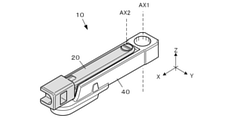
- FIG. 2 is a perspective view showing an example of a usage state of the auxiliary arm 10 (parts connecting structure).
- FIG. 3 is a perspective external view showing an example of the degeneracy limit state of the auxiliary arm 10.
- FIG. 4 is a perspective external view showing an example of the extension limit state of the auxiliary arm 10. It was
- the three orthogonal axes are the coordinates of the right-handed system, and the X-axis direction indicates the expansion / contraction direction and the front-back direction as the parts connecting structure of the auxiliary arm 10.
- the plus side of the X-axis is the extension direction and is forward.
- the Y-axis direction is a left-right direction for the auxiliary arm 10 and indicates a swing direction.
- the Y-axis plus side is to the left.
- the Z-axis direction indicates a vertical direction for the auxiliary arm 10, and the Z-axis plus side is upward. It was
- the auxiliary arm 10 can rotate about the movable part 20 connected to the weapon 4 via the connecting part 5 (first external part) and the body part 6 (second external part) of the doll toy 2 by the axis AX1. It has a base part 40, which is connected to the base part 40. It was
- the movable part 20 is slidably connected to the base part 40.
- the movable part 20 is fully pushed into the base part 40 and accommodated, and the auxiliary arm 10 is in the most degenerate state (Fig.). See 1).
- the movable part 20 is pulled out from the base part 40 to the full extent, the auxiliary arm 10 is extended to the maximum, and the shaft AX2 makes it swingable relative to the base part 40. (See FIG. 2). It was
- the connecting part 5 is rotatably connected to the movable part 20 by the shaft AX3.
- the auxiliary arm 10 has 1) the orientation of the base part 40 with respect to the body part 6, 2) the degree of withdrawal of the movable part 20 from the base part 40, and 3) the base part of the movable part 20 in the extension limit state. It can change into various forms depending on the degree of swinging with respect to 40 and the degree of rotation of the connecting part 5 with respect to the movable part 20. Of course, even if the auxiliary arm 10 itself is focused on, it can be freely expanded and contracted and bent. Then, the auxiliary arm 10 seems to support the weapon 4 in various postures corresponding to various poses of the doll toy 2. It was
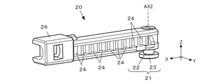
- FIG. 5 is a perspective external view showing an example of the movable part 20.
- the movable part 20 is a rod-shaped member, and has a protruding portion 21 provided on the lower surface of an end portion on the degenerate direction side (rear end side; an end portion on the minus side of the X-axis) and a protruding portion 21 on each of the left and right side surfaces in the expansion and contraction direction. It includes a plurality of recesses 24 arranged along the line, and a first connecting portion 26 provided at an end portion on the extension direction side (front end side; end portion on the X-axis plus side). It was
- the protruding portion 21 has a columnar neck portion 22 protruding downward (Z-axis minus direction), and a head portion 23 at the lower end thereof and wider than the neck portion 22.
- the head 23 forms a circular flange protruding from the neck 22 in a flange shape.
- the diameter of the head 23 is set to be the same as or slightly smaller than the left-right width of the movable part 20. It was
- the first connecting portion 26 is a portion to which the connecting part 5 (first external part; see FIG. 2) for connecting the weapon 4 is connected. It was
- FIG. 6 is a top view showing an example of the base part 40.
- FIG. 7 is an XZ cross-sectional view showing an example of the base part 40.
- FIG. 8 is a perspective external view showing an example of the base part 40 as viewed from diagonally below.
- the base part 40 is a rod-shaped part that accommodates the movable part 20 so as to be relatively movable in a predetermined advancing / retreating direction (expansion / contraction direction for the auxiliary arm 10; X-axis direction), and has a symmetrical shape.
- the base part 40 includes a second connecting portion 42, a first guide portion 50, and a second guide portion 60, which are insertion holes through which the shaft AX1 of the fuselage part 6 (second external part; see FIG. 2) is inserted. It has a third guide unit 70. It was
- the first guide portion 50 is a portion corresponding to the left and right side walls of the accommodation space for accommodating the movable part 20, and is in sliding contact with the left and right side surfaces of the movable part 20 to guide the movable part 20 in a predetermined advancing / retreating direction. It was
- the first guide portion 50 has elastic protrusions 51 on the surfaces facing the left and right side surfaces of the movable part 20, respectively.
- the elastic protrusion 51 has a convex size capable of interfering with the concave portion 24 of the movable part 20, and the tip portion has a shape that can be fitted into the concave portion 24. It was
- the second guide portion 60 is a portion corresponding to the bottom surface of the accommodation space for accommodating the movable parts 20, and is the first rail portion 61 on the degenerate side (X-axis minus side) and the extension side (X side plus side). It has a second rail portion 62 and a receiving portion 63 which is a receiving space for inserting the protruding portion 21 of the movable part 20 into these rail portions. It was
- the first rail portion 61 and the second rail portion 62 are provided so as to sandwich the receiving portion 63, that is, at intervals of the receiving portion 63.
- the first rail portion 61 and the second rail portion 62 are arranged linearly along the advancing / retreating direction (expansion / contraction direction for the auxiliary arm 10) of the movable part 20 with the receiving portion 63 interposed therebetween.
- the first rail portion 61 and the second rail portion 62 are provided on a straight line with a space of the receiving portion 63 in the advancing / retreating direction. It was
- the front-rear width (length in the X-axis direction: length in the front-rear direction) of the receiving portion 63 is set to be larger than the diameter of the head 23 of the protrusion 21, that is, the maximum front-rear width of the protrusion 21.
- the left-right width of the receiving portion 63 is set to be larger than the diameter of the head 23 of the protruding portion 21, that is, the maximum left-right width of the protruding portion 21.
- Receiving part 6 3 can insert the protruding portion 21 from the upper side to the lower side until the protruding portion 21 reaches a position below the first rail portion 61 and the second rail portion 62.
- the position of the receiving portion 63 is indicated to the user by the marking portions 57 provided on the left and right side surfaces of the first guide portion 50 (see FIGS. 4, 8 and 9), and the positioning when assembling the auxiliary arm 10 is easy. Is.
- the mark portion 57 (instruction display) is provided at a position that can be visually recognized from the outside in the first guide portion 50 and at a position corresponding to the position where the receiving portion 63 is provided.
- the first rail portion 61 has a pair of elastic protrusions 64 on the facing surfaces of the grooves.
- the elastic protrusion 64 is formed on the surface on the extension side (X-axis plus side) of the neck portion 22 of the protrusion 21 when the protrusion 21 is located at the accommodation position P1 (shown by a broken line circle in FIG. 6) corresponding to the degenerate side limit position. It is projected at a position immediately before the accommodation position P1 so as to be in close contact with the accommodation position.
- the protrusion 21 can move beyond the elastic protrusion 64 to the accommodation position P1 by elastically deforming the elastic protrusion 64.
- the elastic protrusion 64 must be exceeded again, and the elastic projection 64 functions to hold the protrusion 21 at the accommodation position P1. It was
- the second rail portion 62 also has a pair of elastic protrusions 64 on the facing surfaces of the grooves.
- the elastic protrusion 64 is in close contact with the degenerate side (X-axis minus side) surface of the neck portion 22 of the protrusion 21 when the protrusion 21 is located at the extension position P2 (shown by a broken line circle in FIG. 6), which is the limit position on the extension side. As such, it is projected at a position immediately before the extension position P2.
- the protrusion 21 can move beyond the elastic protrusion 64 to the extension position P2 by elastically deforming the elastic protrusion 64.
- the elastic protrusion 64 must be exceeded again, and the elastic protrusion 64 functions to hold the protrusion 21 at the extension position P2.
- the guide range W1 of the first guide unit 50 is wider than the guide range W2 of the second guide unit 60 on the degenerate side (X-axis minus side). Although it is set, on the contrary, on the extension side (X-axis plus side), it reaches only before the extension position P2. In other words, at one end of one end in the expansion / contraction direction, there is no guidance by the first guide unit 50, and there is guidance by the second guide unit 60. It was
- the protruding portion 21 of the movable part 20 reaches the extended position P2
- the protruding portion 21 is held at the extended position P2 by the action of the elastic protrusion 64.
- the movable part 20 does not shift in the degenerate direction, and the movable part 20 does not come into contact with the first guide portion 50 again to make the swinging operation difficult.
- an appropriate friction tacisting resistance
- the extension position P2 is a position that can be said to be a bearing portion with respect to the protrusion 21. It was
- the movable part 20 is already the first from the process until the protruding portion 21 of the movable part 20 reaches the accommodation position P1.
- the posture is maintained by the guide portion 50, and the base part 40 cannot be swung.
- the projecting portion 21 of the movable part 20 reaches the accommodating position P1
- the projecting portion 21 is held at the accommodating position P1 by the action of the elastic projection 64.
- the elastic protrusion 64 tightens the neck portion 22 to generate an appropriate resistance between the protrusion 21 and the second guide portion 60, and the movable part 20 is accommodated by the base part 40. The state is retained. It was
- the third guide portion 70 is a wall portion provided in a convex shape downward from the front lower surface of the base part 40, and has a substantially horseshoe shape when viewed from the lower surface.
- the degenerate side of the third guide portion 70 reaches a position where it hangs on the left and right of the receiving portion 63 of the second guide portion 60.
- the left and right internal widths of the third guide portion 70 are set to be slightly larger than the diameter of the head 23 of the protruding portion 21. It was
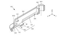
- FIG. 9 is a perspective view for explaining the assembly of the auxiliary arm 10 and the expansion / contraction operation.
- the base part 40 is cut and represented by an XZ cross section for convenience. It was
- the user While referring to the alignment of the mark portion 57, the user specifically positions the protrusion 21 at a position directly above the Z-axis plus side of the mark portion 57, and then positions the protrusion 21 of the movable part 20. 2 Insert the guide portion 60 into the receiving portion 63 from above. The user can know the limit of the insertion by the lower surface of the portion of the movable part 20 having the recess 24 touching the upper surface of the second rail portion 62 of the second guide portion 60. It was
- the protruding portion 21 inserted into the receiving portion 63 is not engaged with either the first rail portion 61 or the second rail portion 62, but the outer surface of the head 23 is the third guide portion 70.
- Left-right movement (movement in the Y-axis direction) is restricted by the inner surface of the surface, and is guided in the expansion / contraction direction (X-axis direction). Therefore, when the user slides the movable part 20 in the extension direction (X-axis plus direction) or the degenerate direction (X-axis minus direction) with the protrusion 21 guided, the protrusion 21 becomes the first rail portion 61 or Engagement with any of the second rail portions 62 completes the connection.
- the movable part 20 has a shape in which the head 23 of the protruding portion 21 protrudes from the accommodation space of the base part 40. It was
- the elastic protrusion 51 projecting from the inner surface of the first guide portion 50 becomes the same height as the recess 24 of the movable part 20.
- the elastic protrusion 51 overcomes the threshold of the adjacent recesses 24 while elastically deforming, thereby creating an appropriate feeling of operational resistance in the sliding operation of the movable part 20 and providing a feeling of operation. Improve quality. Further, the resistance when the elastic protrusion 51 gets over while elastically deforming produces an action of holding the current position of the movable part 20 with respect to the base part 40. It was
- the protruding portion 21 passes through the receiving portion 63. Since the receiving portion 63 does not have a structure corresponding to a rail portion that sandwiches and guides the neck portion 22 of the protruding portion 21 like the first rail portion 61 and the second rail portion 62, the protruding portion 21 seems to be the first rail. It may appear that it cannot move smoothly between the portion 61 and the second rail portion 62. However, while passing through the receiving portion 63, the head 23 of the protruding portion 21 is guided by the third guide portion 70, so that the head 23 smoothly slides between the first rail portion 61 and the second rail portion 62. .. It was
- the present embodiment it is possible to realize a parts connecting structure in which the number of parts is smaller than in the conventional case, and which can be expanded and contracted and can be bent.
- a part connection structure that can be expanded and contracted and bent can be realized with only two pieces.
- the structure is simple and simple, it is easy to assemble, and the manufacturing cost can be suppressed. It was
- the design of the doll toy 2 to which the present invention is applicable is not limited to this.
- it may be a beast-type or insect-type robot weapon, a multi-legged tank, or the like.
- the doll toy 2 may be a figure of a person appearing in a manga or an animation. It was
- the head 23 is extended from the lower end of the neck 22 to the entire circumference to form a disk-shaped so-called flange shape, but the shape of the head 23 is this. Not limited to.
- the head 23 may be partially extended or widened only in the left-right direction.
- the head 23 may be spherical.
- the movable part 20 is connected to the base part 40 by a ball joint at the extension position P2, so that it is possible to realize a structure that can swing not only left and right but also up and down. Is.
Landscapes
- Toys (AREA)
Applications Claiming Priority (2)
| Application Number | Priority Date | Filing Date | Title |
|---|---|---|---|
| JP2020-149636 | 2020-09-07 | ||
| JP2020149636A JP7023336B1 (ja) | 2020-09-07 | 2020-09-07 | パーツ連結構造及び人形玩具 |
Publications (1)
| Publication Number | Publication Date |
|---|---|
| WO2022050112A1 true WO2022050112A1 (ja) | 2022-03-10 |
Family
ID=78240617
Family Applications (1)
| Application Number | Title | Priority Date | Filing Date |
|---|---|---|---|
| PCT/JP2021/030819 Ceased WO2022050112A1 (ja) | 2020-09-07 | 2021-08-23 | パーツ連結構造及び人形玩具 |
Country Status (3)
| Country | Link |
|---|---|
| JP (2) | JP7023336B1 (https=) |
| CN (2) | CN116351077A (https=) |
| WO (1) | WO2022050112A1 (https=) |
Families Citing this family (2)
| Publication number | Priority date | Publication date | Assignee | Title |
|---|---|---|---|---|
| KR20240165925A (ko) | 2022-03-31 | 2024-11-25 | 스미토모 겐키 가부시키가이샤 | 쇼벨의 관리시스템, 쇼벨의 관리방법 |
| JP7675272B1 (ja) * | 2024-10-25 | 2025-05-12 | 株式会社バンダイ | 模型玩具、及び模型部品 |
Citations (8)
| Publication number | Priority date | Publication date | Assignee | Title |
|---|---|---|---|---|
| JPS6069187U (ja) * | 1983-10-19 | 1985-05-16 | 株式会社タカラ | 玩具構成部品の接続構造 |
| JPS6160995U (https=) * | 1984-09-27 | 1986-04-24 | ||
| JPS6180083U (https=) * | 1984-10-31 | 1986-05-28 | ||
| JPS6236793U (https=) * | 1985-08-21 | 1987-03-04 | ||
| JPS6278989U (https=) * | 1985-10-31 | 1987-05-20 | ||
| US4680019A (en) * | 1986-01-29 | 1987-07-14 | Kenner Parker Toys Inc. | Toy figure with individually posable limbs |
| JPH06269572A (ja) * | 1993-03-22 | 1994-09-27 | Takara Co Ltd | ロボット玩具等の腕部材の作動装置 |
| WO2014148073A1 (ja) * | 2013-03-22 | 2014-09-25 | 株式会社バンダイ | 形態変化玩具 |
Family Cites Families (9)
| Publication number | Priority date | Publication date | Assignee | Title |
|---|---|---|---|---|
| US5735726A (en) * | 1996-12-09 | 1998-04-07 | Telco Creations, Inc. | Animated sitting and standing santa character |
| CN2284635Y (zh) * | 1997-02-05 | 1998-06-24 | 林喜春 | 可往复位移及回转的传动装置 |
| JP3794124B2 (ja) * | 1997-09-17 | 2006-07-05 | 株式会社セガ | 走行模擬装置 |
| CN2897362Y (zh) * | 2006-04-18 | 2007-05-09 | 汕头市澄海区铭明塑胶实业有限公司 | 一种机器人玩具 |
| JP2009160238A (ja) * | 2008-01-07 | 2009-07-23 | Tomy Co Ltd | 歩行玩具 |
| JP2009247659A (ja) * | 2008-04-08 | 2009-10-29 | Tomy Co Ltd | 揺動玩具 |
| CN201492930U (zh) * | 2009-08-17 | 2010-06-02 | 浙江省岱山县兴发玩具厂 | 在架子上翻动的人形玩具 |
| JP6162270B1 (ja) * | 2016-01-28 | 2017-07-12 | 株式会社バンダイ | 人型玩具 |
| JP6303051B1 (ja) * | 2017-06-28 | 2018-03-28 | 株式会社バンダイ | 人形玩具 |
-
2020
- 2020-09-07 JP JP2020149636A patent/JP7023336B1/ja active Active
-
2021
- 2021-08-23 WO PCT/JP2021/030819 patent/WO2022050112A1/ja not_active Ceased
- 2021-08-31 CN CN202310342762.9A patent/CN116351077A/zh active Pending
- 2021-08-31 CN CN202111014275.7A patent/CN113577785B/zh active Active
-
2022
- 2022-02-08 JP JP2022018130A patent/JP7624939B2/ja active Active
Patent Citations (8)
| Publication number | Priority date | Publication date | Assignee | Title |
|---|---|---|---|---|
| JPS6069187U (ja) * | 1983-10-19 | 1985-05-16 | 株式会社タカラ | 玩具構成部品の接続構造 |
| JPS6160995U (https=) * | 1984-09-27 | 1986-04-24 | ||
| JPS6180083U (https=) * | 1984-10-31 | 1986-05-28 | ||
| JPS6236793U (https=) * | 1985-08-21 | 1987-03-04 | ||
| JPS6278989U (https=) * | 1985-10-31 | 1987-05-20 | ||
| US4680019A (en) * | 1986-01-29 | 1987-07-14 | Kenner Parker Toys Inc. | Toy figure with individually posable limbs |
| JPH06269572A (ja) * | 1993-03-22 | 1994-09-27 | Takara Co Ltd | ロボット玩具等の腕部材の作動装置 |
| WO2014148073A1 (ja) * | 2013-03-22 | 2014-09-25 | 株式会社バンダイ | 形態変化玩具 |
Also Published As
| Publication number | Publication date |
|---|---|
| JP2022044151A (ja) | 2022-03-17 |
| CN116351077A (zh) | 2023-06-30 |
| CN113577785B (zh) | 2023-04-21 |
| JP7023336B1 (ja) | 2022-02-21 |
| JP7624939B2 (ja) | 2025-01-31 |
| JP2022061039A (ja) | 2022-04-15 |
| CN113577785A (zh) | 2021-11-02 |
Similar Documents
| Publication | Publication Date | Title |
|---|---|---|
| JP7465188B2 (ja) | 可動構造及び人形体 | |
| CN114832390B (zh) | 人型玩具 | |
| CN108472549B (zh) | 人形玩具 | |
| JP7023336B1 (ja) | パーツ連結構造及び人形玩具 | |
| JP7129217B2 (ja) | 人形の腰部関節構造及び人形 | |
| JP7112581B1 (ja) | 玩具部品及び人形玩具 | |
| JP6604996B2 (ja) | 人型玩具 | |
| JP5650266B2 (ja) | 形態変化玩具 | |
| JP6636992B2 (ja) | 人型玩具 | |
| JP7336612B1 (ja) | 模型玩具及び関節構造体 | |
| CN1894013B (zh) | 形态变形玩具 | |
| JP7105105B2 (ja) | 人形の関節構造及び人形 | |
| JP7614285B1 (ja) | 模型玩具、及び可動構造体 | |
| CN114733212A (zh) | 可动构造体和玩具 | |
| JP7242947B1 (ja) | 模型玩具、及び可動構造体 | |
| JP7455052B2 (ja) | 組立玩具部品及び組立玩具 | |
| JP7342200B1 (ja) | 玩具の射出機構 | |
| JP7474108B2 (ja) | 可動構造および玩具 | |
| JP7808229B1 (ja) | 模型部品、および模型玩具 | |
| JP7842430B1 (ja) | 手関節構造及び模型 | |
| JP7738206B1 (ja) | 模型部品、および模型玩具 | |
| CN117919728A (zh) | 模型玩具和可动构造体 | |
| JP2014198272A (ja) | 形態変化玩具 | |
| HK1210981B (en) | Transformable toy |
Legal Events
| Date | Code | Title | Description |
|---|---|---|---|
| 121 | Ep: the epo has been informed by wipo that ep was designated in this application |
Ref document number: 21864170 Country of ref document: EP Kind code of ref document: A1 |
|
| NENP | Non-entry into the national phase |
Ref country code: DE |
|
| 122 | Ep: pct application non-entry in european phase |
Ref document number: 21864170 Country of ref document: EP Kind code of ref document: A1 |