WO2022049936A1 - Structure de refroidissement pour moteur à combustion interne - Google Patents
Structure de refroidissement pour moteur à combustion interne Download PDFInfo
- Publication number
- WO2022049936A1 WO2022049936A1 PCT/JP2021/027988 JP2021027988W WO2022049936A1 WO 2022049936 A1 WO2022049936 A1 WO 2022049936A1 JP 2021027988 W JP2021027988 W JP 2021027988W WO 2022049936 A1 WO2022049936 A1 WO 2022049936A1
- Authority
- WO
- WIPO (PCT)
- Prior art keywords
- introduction port
- refrigerant
- cylinder head
- water jacket
- internal combustion
- Prior art date
Links
Images


Classifications
-
- F—MECHANICAL ENGINEERING; LIGHTING; HEATING; WEAPONS; BLASTING
- F01—MACHINES OR ENGINES IN GENERAL; ENGINE PLANTS IN GENERAL; STEAM ENGINES
- F01P—COOLING OF MACHINES OR ENGINES IN GENERAL; COOLING OF INTERNAL-COMBUSTION ENGINES
- F01P3/00—Liquid cooling
- F01P3/02—Arrangements for cooling cylinders or cylinder heads
-
- F—MECHANICAL ENGINEERING; LIGHTING; HEATING; WEAPONS; BLASTING
- F02—COMBUSTION ENGINES; HOT-GAS OR COMBUSTION-PRODUCT ENGINE PLANTS
- F02F—CYLINDERS, PISTONS OR CASINGS, FOR COMBUSTION ENGINES; ARRANGEMENTS OF SEALINGS IN COMBUSTION ENGINES
- F02F1/00—Cylinders; Cylinder heads
- F02F1/02—Cylinders; Cylinder heads having cooling means
- F02F1/10—Cylinders; Cylinder heads having cooling means for liquid cooling
- F02F1/14—Cylinders with means for directing, guiding or distributing liquid stream
-
- F—MECHANICAL ENGINEERING; LIGHTING; HEATING; WEAPONS; BLASTING
- F02—COMBUSTION ENGINES; HOT-GAS OR COMBUSTION-PRODUCT ENGINE PLANTS
- F02F—CYLINDERS, PISTONS OR CASINGS, FOR COMBUSTION ENGINES; ARRANGEMENTS OF SEALINGS IN COMBUSTION ENGINES
- F02F1/00—Cylinders; Cylinder heads
- F02F1/24—Cylinder heads
- F02F1/26—Cylinder heads having cooling means
- F02F1/36—Cylinder heads having cooling means for liquid cooling
- F02F1/40—Cylinder heads having cooling means for liquid cooling cylinder heads with means for directing, guiding, or distributing liquid stream
Definitions
- the present invention relates to a cooling structure of an internal combustion engine in which a water jacket is formed inside a cylinder block and a cylinder head.
- a technique for controlling the flow of a refrigerant for example, engine cooling water
- a spacer for example, a spacer inside a water jacket formed around a cylinder bore of an internal combustion engine
- a cooling structure has been proposed in which the flow direction and flow velocity of the refrigerant in the water jacket are adjusted by spacers so that a plurality of cylinder bores can be cooled evenly (see Patent Documents 1 and 2).
- the flow of the refrigerant may be biased depending on the position of the introduction port for introducing the refrigerant into the water jacket and the shape of the water jacket. For example, most of the refrigerant introduced into the water jacket on the cylinder block side may flow out to the cylinder head side as it is, and the cooling efficiency of the cylinder bore may decrease.
- One of the purposes of this case is to provide a cooling structure for an internal combustion engine, which was created in light of the above-mentioned problems and can improve the cooling efficiency by the refrigerant with a simple configuration. Not limited to this purpose, it is also possible to exert an action / effect derived from each configuration shown in the “mode for carrying out the invention” described later, which cannot be obtained by the conventional technique. It can be positioned as a purpose.
- the cooling structure of the disclosed internal combustion engine includes a water jacket formed inside the cylinder block and the cylinder head surrounding the cylinder bore of the internal combustion engine, a spacer arranged inside the water jacket, and a water jacket on the cylinder block side. It is equipped with a first introduction port for introducing a refrigerant into the engine.
- the spacer is provided with a weir portion located on the cylinder head side of the first introduction port and a rib erected on the weir portion.
- the cooling efficiency by the refrigerant can be improved with a simple configuration.
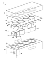
- FIG. 1 It is an exploded perspective view of the internal combustion engine to which the cooling structure as an Example is applied. It is a top view of the spacer shown in FIG. It is a figure which shows the main part of the spacer shown in FIG. 2 in an enlarged manner. It is a perspective view of the spacer shown in FIG. It is a perspective view of the spacer shown in FIG.
- FIG. 1 is a schematic exploded perspective view for explaining a configuration of an internal combustion engine 1 to which a cooling structure as an embodiment is applied.
- the internal combustion engine 1 is, for example, an engine such as a gasoline engine or a diesel engine (in this example, a four-cylinder engine), and is mounted in an engine room of a vehicle.
- the internal combustion engine 1 includes a cylinder block 2 and a cylinder head 3 fixed to the cylinder block 2.
- a plurality (four in this example) of cylindrical cylinder bores 4 having a combustion chamber inside the cylinder block 2 are formed side by side.
- the cylinder head 3 is formed with a ceiling surface portion 5 forming the upper surface of the combustion chamber.
- the shape of the cylinder bore 4 is, for example, a cylinder, and the shape of the ceiling surface portion 5 is, for example, a cone.
- An intake port and an exhaust port (not shown) are connected to the ceiling surface portion 5.
- a gasket 8 is sandwiched between the cylinder block 2 and the cylinder head 3.
- the gasket 8 has a function of ensuring the airtightness of each cylinder and the liquidtightness of the cooling water and the lubricating oil.
- the gasket 8 is provided with a plurality of through holes 31 drilled at positions corresponding to the cylinder bores 4 and a plurality of communication holes 32 drilled around the through holes 31 and smaller than the through holes 31. ..
- the plurality of through holes 31 communicate the cylinder bore 4 and the ceiling surface portion 5.
- the plurality of communication holes 32 communicate the water jacket 6 provided in the cylinder block 2 and the water jacket 7 provided in the cylinder head 3.
- a water jacket 6 surrounding the cylinder bore 4 is formed on the cylinder block 2.
- the water jacket 6 has a shape open to the upper surface side (the side on which the cylinder head 3 is arranged) of the cylinder block 2.
- the cylinder head 3 is formed with a water jacket 7 that surrounds the ceiling surface portion 5, an intake port, an exhaust port, etc. (not shown).
- the water jacket 7 has a shape that is open to the lower surface side (the side on which the cylinder block 2 is arranged) of the cylinder head 3.
- Refrigerant for example, engine cooling water
- Refrigerant flows inside the water jackets 6 and 7, and the cylinder block 2 and the cylinder head 3 are cooled by the refrigerant. Further, the water jacket 6 on the cylinder block 2 side communicates with the water jacket 7 on the cylinder head 3 side through a plurality of communication holes 32 drilled in the gasket 8.
- an inlet portion 9 serving as an inlet of the refrigerant to the water jacket 6 is provided on the intake side of the cylinder block 2, on the intake side of the cylinder block 2, an inlet portion 9 serving as an inlet of the refrigerant to the water jacket 6 is provided.
- the intake side is a side on which the intake port and the intake manifold are arranged in a top view, and is the side indicated by reference numeral A in FIGS. 1 and 2.
- the exhaust side is a side on which an exhaust port and an exhaust manifold are arranged in a top view, and is a side indicated by reference numeral B in FIGS. 1 and 2.
- the inlet portion 9 is a portion formed in an enlarged shape of the water jacket 6 in the diameter expansion direction of the cylinder bore 4. As shown in FIG. 2, the position of the inlet portion 9 is arranged on the intake side A of the cylinder bore 4 located at the end portion of the plurality of cylinder bores 4 arranged in a row.
- the cylinder block 2 is provided with a first introduction port 21 that connects the outer peripheral surface thereof and the inlet portion 9.
- the first introduction port 21 is a portion serving as a passage for introducing the refrigerant into the water jacket 6 on the cylinder block 2 side.
- the position of the first introduction port 21 is set to a position separated below the uppermost surface 2a of the cylinder block 2.
- the communication holes 32 drilled in the gasket 8 the one arranged directly above the inlet portion 9 is referred to as a second introduction port 22.
- the second introduction port 22 is a communication hole 32 for communicating the water jacket 6 on the cylinder block 2 side and the water jacket 7 on the cylinder head 3 side, and is provided at a position overlapping the inlet portion 9 in a top view.
- the second introduction port 22 for communicating the water jacket 6 on the cylinder block 2 side and the water jacket 7 on the cylinder head 3 side includes holes and openings other than the communication holes 32 drilled in the gasket 8.
- a passage for communicating these may be formed in the cylinder block 2 and the cylinder head 3, and the joint portion of the passage may be referred to as a second introduction port 22. Therefore, the second introduction port 22 is not necessarily formed in the gasket 8, in other words, the second introduction port 22 may exist even in the internal combustion engine 1 without the gasket 8.
- a spacer 10 which is a member for controlling the flow of the refrigerant is arranged inside the water jacket 6, a spacer 10 which is a member for controlling the flow of the refrigerant is arranged.
- the internal combustion engine 1 shown in FIG. 1 is provided with a spacer 10 having an exhaust side spacer 11 and an intake side spacer 12.
- the exhaust side spacer 11 is a spacer inserted into the water jacket 6 on the exhaust side B rather than the cylinder bore 4.
- the intake side spacer 12 is a spacer inserted into the water jacket 6 on the intake side A rather than the cylinder bore 4.
- the approximate shape of the exhaust side spacer 11 and the intake side spacer 12 is a curved surface shape corresponding to the internal shape of the water jacket 6, and is similar to a shape in which a plurality of tubular surfaces are connected in a waveform in a top view.
- the black arrow in FIG. 2 indicates the flow direction of the refrigerant inside the water jacket 6.
- the exhaust side spacer 11 is formed so that the height becomes lower toward the upstream side in the flow direction of the refrigerant inside the water jacket 6, that is, toward the inlet portion 9 (from the upper right to the lower left in FIG. 1). This makes it easier for the refrigerant to flow to the cylinder head 3 side (upward) of the exhaust side spacer 11.
- the downstream side (upper right side in FIG. 1) of the refrigerant inside the water jacket 6 of the exhaust side spacer 11 is about the same as the height of the intake side spacer 12, and is larger than the depth of the water jacket 6. It is set low.
- the intake side spacer 12 is formed in a shape that enters the inside of the inlet portion 9 from the water jacket 6. As shown in FIGS. 3 to 5, the intake side spacer 12 is provided with a weir portion 13, a rib 14, a wall portion 15, and a terrace portion 16.
- the weir portion 13 is a planar portion located on the cylinder head 3 side of the first introduction port 21.
- a weir portion 13 is provided between the first introduction port 21 and the second introduction port 22 inside the inlet portion 9.
- the weir portion 13 is arranged at a position that blocks the shortest path from the first introduction port 21 to the second introduction port 22.
- the weir portion 13 of this embodiment is provided at a position lower than the height of the intake side spacer 12, and the shape thereof is formed along the shape of the inlet portion 9 in a top view.
- the weir portion 13 is preferably formed to have a shape inclined toward the cylinder head 3 side (upward) toward the downstream side in the flow direction of the refrigerant, and more preferably has a smooth curved surface shape so that the gradient gradually becomes steeper. ..
- the refrigerant flowing from the first introduction port 21 by the weir portion 13 flows along the lower surface side of the weir portion 13, and is in the counterclockwise direction indicated by the black arrow, that is, the exhaust side B of the cylinder block 2. It is guided toward the upper left while gradually turning to.
- the weir portion 13 bends the flow of the refrigerant flowing from the first introduction port 21 inward in the radial direction of the cylinder bore 4 into the inlet portion 9 in the circumferential direction of the cylinder bore 4, and also bends the flow of the refrigerant flowing into the inlet portion 9 in the circumferential direction.
- the flow of the refrigerant toward the introduction port 22 side is bent in the circumferential direction of the cylinder bore 4 and functions to circulate in the water jacket 6 on the cylinder block 2 side.
- a part of the refrigerant guided in the counterclockwise direction flows on the cylinder head 3 side (upper side) of the spacer 10 and circulates around the cylinder bore 4 to the second introduction port 22 side (upper surface side) of the weir portion 13. To reach.
- the rib 14 is a plate-shaped portion erected on the surface (upper surface side) of the weir portion 13 on the side of the second introduction port 22 and rectifies the refrigerant on the second introduction port 22 side of the weir portion 13. be.
- the flow of the refrigerant circulating around the cylinder bore 4 is indicated by a white arrow in FIG.
- the rib 14 has a shape that guides the flow of the refrigerant toward the second introduction port 22.
- the rib 14 of this embodiment is formed by arranging two flat plates in parallel, and the refrigerant flows between the two flat plates into the second introduction port 22.
- the rib 14 has a shape that extends linearly from the second introduction port 22 toward the upstream side in the flow direction of the refrigerant when viewed from above.
- the rib 14 of the present embodiment extends parallel to the line connecting the boundary between the water jacket 6 and the inlet portion 9 and the second introduction port 22 when viewed from above. Further, the second introduction port 22 is arranged between the two ribs 14 in a top view.
- the rib 14 is a refrigerant that has flowed from the gap between the weir portion 13 and the water jacket 6 and the inlet portion 9 to the surface of the weir portion 13 on the side of the second introduction port 22 without circulating around the cylinder bore 4. By rectifying the flow, it also has an effect of not disturbing the flow of the refrigerant near the second introduction port 22.
- the wall portion 15 is a plate-shaped portion erected on the surface (upper surface side) of the weir portion 13 on the side of the second introduction port 22, and the refrigerant on the second introduction port 22 side of the weir portion 13 is first introduced. Prevents backflow to the mouth 21 side.
- the wall portion 15 is arranged on the upstream side of the inlet portion 9 from the rib 14 (in this embodiment, the upstream end edge of the weir portion 13 in the flow direction of the refrigerant), and is from the second introduction port 22 side of the weir portion 13.
- the refrigerant that has tried to flow back toward the first introduction port 21 through the gap between the weir portion 13 and the inlet portion 9 is guided in the direction along the rib 14 as shown by the white arrow in FIG. Works like.
- the terrace portion 16 is a terrace-shaped portion formed on the surface (upper surface side) of the weir portion 13 on the side of the second introduction port 22 so as to bulge upward from the weir portion 13.
- the terrace portion 16 projects from the inlet portion 9 when viewed from above, and extends from the inlet portion 9 to the water jacket 6 on the cylinder block 2 side on the downstream side in the flow direction of the refrigerant.
- the upper surface of the terrace portion 16 is formed in a planar shape and comes into surface contact with the lower surface of the gasket 8.
- the terrace portion 16 prevents the refrigerant on the second introduction port 22 side from the weir portion 13 from flowing out again in the direction along the peripheral surface of the cylinder bore 4, and also prevents the refrigerant from flowing out from the inlet portion 9 on the downstream side in the distribution direction. It functions so that the refrigerant flowing through the water jacket 6 does not flow into the second introduction port 22 side from the weir portion 13.
- the refrigerant circulating around the cylinder bore 4 can easily flow into the second introduction port 22.
- the refrigerant that has flowed into the water jacket 7 on the cylinder head 3 side through the second introduction port 22 is discharged to the outside of the internal combustion engine 1 through an outlet (not shown).
- the weir portion 13 of the spacer 10 is arranged above the first introduction port 21.
- the refrigerant flowing from the first introduction port 21 can be suppressed from flowing to the cylinder head 3 side as it is, and the refrigerant can be prevented from flowing into the water jacket 6 on the cylinder block 2 side. It becomes easy to circulate with.
- the rib 14 erected on the weir portion 13 the flow of the refrigerant in the vicinity of the weir portion 13 can be rectified. Therefore, the cooling efficiency by the refrigerant can be improved with a simple configuration.
- the cooling structure is provided with a second introduction port 22 for communicating the water jacket 6 on the cylinder block 2 side and the water jacket 7 on the cylinder head 3 side, and the first introduction port 21 and the second introduction port 21.
- a dam portion 13 is arranged between the 22 and the dam portion 13.
- the refrigerant on the upper surface of the weir portion 13 (the surface on the second introduction port 22 side) can be rectified.
- the refrigerant can be efficiently flowed through the second introduction port 22 to the water jacket 7 on the cylinder head 3 side. Therefore, the cooling efficiency by the refrigerant can be improved with a simple configuration.
- the second introduction port 22 is located on the cylinder head 3 side (upper side) of the weir portion 13, and the weir portion 13 directs the refrigerant flowing from the first introduction port 21 along the peripheral surface of the cylinder bore 4. It is formed in a shape that guides to. Further, the refrigerant induced by the weir portion 13 circulates on the peripheral surface of the cylinder bore 4 and flows into the cylinder head 3 side of the weir portion 13. As a result, it becomes easy to circulate the refrigerant along the peripheral surface of the cylinder bore 4, and the cooling efficiency by the refrigerant can be further improved.
- the surface (upper surface) of the weir portion 13 on the cylinder head 3 side is formed so as to be inclined toward the cylinder head side toward the downstream side in the flow direction of the refrigerant.
- the refrigerant circulating around the cylinder bore 4 can be efficiently and smoothly flowed to the second introduction port 22, and the cooling efficiency can be improved.
- the surface of the weir portion 13 not only the surface (upper surface) on the cylinder head 3 side but also the surface (lower surface) on the cylinder block 2 side may be inclined.
- the weir portion 13 may be formed in a curved surface shape that is inclined with respect to the flow of the refrigerant flowing in from the first introduction port 21.
- the refrigerant flowing in from the first introduction port 21 can be guided in the upper left direction while gradually turning in the left rotation direction indicated by the black arrow, and the cooling efficiency by the refrigerant can be improved. It can be further improved.
- a wall portion 15 is provided on the intake side spacer 12.
- the wall portion 15 is erected on the surface of the weir portion 13 on the side of the second introduction port 22 to prevent the refrigerant on the side of the second introduction port 22 from flowing back to the side of the first introduction port 21.
- the rib 14 has a shape that extends linearly along the flow direction of the refrigerant flowing through the surface (upper surface) of the weir portion 13 on the cylinder head 3 side when viewed from above. ..
- the rib 14 has a shape extending linearly from the second introduction port 22 toward the radial outer side of the second introduction port 22.
- a plurality of ribs 14 are arranged side by side at intervals in the top view.
- the second introduction port 22 is formed in the gasket 8 sandwiched between the cylinder block 2 and the cylinder head 3, and is arranged between the plurality of ribs 14 when viewed from above.
Landscapes
- Engineering & Computer Science (AREA)
- Chemical & Material Sciences (AREA)
- Combustion & Propulsion (AREA)
- Mechanical Engineering (AREA)
- General Engineering & Computer Science (AREA)
- Cylinder Crankcases Of Internal Combustion Engines (AREA)
Abstract
La présente invention concerne une structure de refroidissement pour un moteur à combustion interne comprenant une chemise d'eau qui entoure les alésages de cylindre d'un moteur à combustion interne et qui est formée à l'intérieur d'un bloc-cylindres et d'une culasse, un élément d'espacement disposé à l'intérieur de la chemise d'eau et un premier orifice d'entrée qui laisse entrer le fluide frigorigène dans la chemise d'eau sur le côté bloc-cylindres. L'élément d'espacement a une partie de barrage positionnée sur le côté de la tête de cylindre du premier orifice d'entrée et une nervure érigée sur la partie de barrage.
Priority Applications (2)
| Application Number | Priority Date | Filing Date | Title |
|---|---|---|---|
| CN202180053657.2A CN116057260A (zh) | 2020-09-01 | 2021-07-28 | 内燃机的冷却结构 |
| JP2022546160A JP7327684B2 (ja) | 2020-09-01 | 2021-07-28 | 内燃機関の冷却構造 |
Applications Claiming Priority (2)
| Application Number | Priority Date | Filing Date | Title |
|---|---|---|---|
| JP2020146595 | 2020-09-01 | ||
| JP2020-146595 | 2020-09-01 |
Publications (1)
| Publication Number | Publication Date |
|---|---|
| WO2022049936A1 true WO2022049936A1 (fr) | 2022-03-10 |
Family
ID=80491977
Family Applications (1)
| Application Number | Title | Priority Date | Filing Date |
|---|---|---|---|
| PCT/JP2021/027988 WO2022049936A1 (fr) | 2020-09-01 | 2021-07-28 | Structure de refroidissement pour moteur à combustion interne |
Country Status (3)
| Country | Link |
|---|---|
| JP (1) | JP7327684B2 (fr) |
| CN (1) | CN116057260A (fr) |
| WO (1) | WO2022049936A1 (fr) |
Citations (2)
| Publication number | Priority date | Publication date | Assignee | Title |
|---|---|---|---|---|
| JP2009243414A (ja) * | 2008-03-31 | 2009-10-22 | Daihatsu Motor Co Ltd | ウォータージャケット用スペーサ |
| JP2009264286A (ja) * | 2008-04-25 | 2009-11-12 | Toyota Motor Corp | 内燃機関の冷却構造 |
-
2021
- 2021-07-28 WO PCT/JP2021/027988 patent/WO2022049936A1/fr active Application Filing
- 2021-07-28 CN CN202180053657.2A patent/CN116057260A/zh active Pending
- 2021-07-28 JP JP2022546160A patent/JP7327684B2/ja active Active
Patent Citations (2)
| Publication number | Priority date | Publication date | Assignee | Title |
|---|---|---|---|---|
| JP2009243414A (ja) * | 2008-03-31 | 2009-10-22 | Daihatsu Motor Co Ltd | ウォータージャケット用スペーサ |
| JP2009264286A (ja) * | 2008-04-25 | 2009-11-12 | Toyota Motor Corp | 内燃機関の冷却構造 |
Also Published As
| Publication number | Publication date |
|---|---|
| CN116057260A (zh) | 2023-05-02 |
| JP7327684B2 (ja) | 2023-08-16 |
| JPWO2022049936A1 (fr) | 2022-03-10 |
Similar Documents
| Publication | Publication Date | Title |
|---|---|---|
| US6481392B1 (en) | Internal combustion engine | |
| JP6575578B2 (ja) | 多気筒エンジンの冷却構造 | |
| JP6299737B2 (ja) | 多気筒エンジンの冷却構造 | |
| JP4375261B2 (ja) | シリンダヘッドおよびこれを用いた水冷エンジン | |
| US7047915B2 (en) | Engine cooling device | |
| JP5939176B2 (ja) | 多気筒エンジンの冷却構造 | |
| US20160018169A1 (en) | Heat exchanger with flow obstructions to reduce fluid dead zones | |
| JP6358284B2 (ja) | エンジンの冷却構造 | |
| US7827973B2 (en) | Integrated positive crankcase ventilation channel | |
| WO2015098705A1 (fr) | Culasse de moteur | |
| US5207189A (en) | Cooling system for an internal combustion engine | |
| JPH0828343A (ja) | 多気筒内燃機関のシリンダブロック | |
| WO2022049936A1 (fr) | Structure de refroidissement pour moteur à combustion interne | |
| JP2000345838A (ja) | 水冷式内燃機関の冷却装置 | |
| JP2017014951A (ja) | エンジンの吸気供給構造 | |
| JP6645154B2 (ja) | インテークマニホールド | |
| JPH09242602A (ja) | シリンダヘッド | |
| JP7064175B2 (ja) | シリンダヘッド | |
| JP7040643B2 (ja) | シリンダヘッド | |
| JP7347755B2 (ja) | エンジンの冷却構造 | |
| JP2017193980A (ja) | 多気筒エンジンの冷却構造 | |
| JP4574360B2 (ja) | 吸気マニホールド | |
| JP2004027901A (ja) | 複数のエアクーラを備えた内燃機関 | |
| JPH06346784A (ja) | 二サイクルエンジンのシリンダ冷却構造 | |
| JP6550969B2 (ja) | エンジンの吸気供給構造 |
Legal Events
| Date | Code | Title | Description |
|---|---|---|---|
| 121 | Ep: the epo has been informed by wipo that ep was designated in this application |
Ref document number: 21863994 Country of ref document: EP Kind code of ref document: A1 |
|
| DPE2 | Request for preliminary examination filed before expiration of 19th month from priority date (pct application filed from 20040101) | ||
| ENP | Entry into the national phase |
Ref document number: 2022546160 Country of ref document: JP Kind code of ref document: A |
|
| NENP | Non-entry into the national phase |
Ref country code: DE |
|
| 122 | Ep: pct application non-entry in european phase |
Ref document number: 21863994 Country of ref document: EP Kind code of ref document: A1 |