WO2022045340A1 - 電動機 - Google Patents
電動機 Download PDFInfo
- Publication number
- WO2022045340A1 WO2022045340A1 PCT/JP2021/031814 JP2021031814W WO2022045340A1 WO 2022045340 A1 WO2022045340 A1 WO 2022045340A1 JP 2021031814 W JP2021031814 W JP 2021031814W WO 2022045340 A1 WO2022045340 A1 WO 2022045340A1
- Authority
- WO
- WIPO (PCT)
- Prior art keywords
- bearing
- electric motor
- rotor
- motor
- conductive member
- Prior art date
- Legal status (The legal status is an assumption and is not a legal conclusion. Google has not performed a legal analysis and makes no representation as to the accuracy of the status listed.)
- Ceased
Links
Images







Classifications
-
- H—ELECTRICITY
- H02—GENERATION; CONVERSION OR DISTRIBUTION OF ELECTRIC POWER
- H02K—DYNAMO-ELECTRIC MACHINES
- H02K11/00—Structural association of dynamo-electric machines with electric components or with devices for shielding, monitoring or protection
- H02K11/40—Structural association with grounding devices
-
- H—ELECTRICITY
- H02—GENERATION; CONVERSION OR DISTRIBUTION OF ELECTRIC POWER
- H02K—DYNAMO-ELECTRIC MACHINES
- H02K5/00—Casings; Enclosures; Supports
- H02K5/04—Casings or enclosures characterised by the shape, form or construction thereof
- H02K5/16—Means for supporting bearings, e.g. insulating supports or means for fitting bearings in the bearing-shields
Definitions
- the present invention relates to an electric motor including two bearing houses and a conductive member that conducts the bearing houses to each other.
- an inner rotor type motor in which a cylindrical rotor having a permanent magnet is arranged coaxially with the stator on the inner diameter side of a cylindrical stator that generates a rotating magnetic field is known.
- This electric motor is used, for example, for rotationally driving a blower fan mounted on an air conditioner.
- the thickness and shape of the insulating layer are determined by the mold forming the rotor core, and when adjusting the capacitance, the mold is changed and the rotor core is used. Cutting etc. is required. Therefore, there is a problem that the capacitance cannot be easily adjusted after the mold of the rotor core is completed.
- an object of the present invention is to provide an electric motor capable of easily adjusting the capacitance between the stator side and the rotor side of the electric motor to suppress the occurrence of electrolytic corrosion.
- One aspect of the motor of the present invention includes a rotor, a shaft arranged along the rotation axis of the rotor and fixed to the rotor, a first bearing arranged on one end side of the shaft, and the above.
- a second bearing arranged on the other end side of the shaft, a stator core arranged on the outer peripheral side of the rotor, a resin outer shell covering the stator core, and outer rings provided by each of the first bearing and the second bearing. It is provided with a conductive member for electrically connecting the bearings.
- a conductive member that covers at least a part of the conductive member is attached to the surface of the resin outer shell.
- the capacitance between the stator side and the rotor side of the motor can be easily adjusted to suppress the occurrence of electrolytic corrosion.
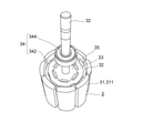
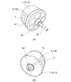
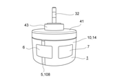
- ⁇ Overall configuration of motor> 1 to 6 are diagrams illustrating the configuration of the electric motor 1 in the present embodiment.
- the electric motor 1 is, for example, a brushless DC motor.
- the electric motor 1 is used, for example, to rotationally drive a blower fan mounted on an outdoor unit of an air conditioner.
- the motor 1 in the present embodiment includes a stator (stator) 2, a rotor (rotor) 3, a motor outer shell (resin outer shell) 10, a bracket 41, and a conduction member 5.
- a stator stator 2
- a rotor rotor 3
- a motor outer shell motor outer shell
- a conduction member 5 conduction member 5.
- an inner rotor type permanent magnet motor 1 in which a cylindrical rotor 3 having a permanent magnet portion 31 is rotatably arranged inside a cylindrical stator 2 that generates a rotating magnetic field is taken as an example. explain.
- the rotor 3 is rotatably arranged with a predetermined gap on the inner peripheral side of the stator core 21 of the stator 2.
- the rotor 3 is a surface magnet type in which a permanent magnet 31 is arranged in an annular shape on an outer peripheral surface facing the stator core 21.
- the permanent magnet 31 is fixed around the shaft 32 via the outer peripheral side iron core 32, the insulating member 33, and the inner peripheral side iron core 35.
- the shaft 32 is supported by a first bearing 33 and a second bearing 34.
- each of the bearing accommodating portion 42 (bracket 41) described later in which the first bearing 33 is accommodated and the second bearing accommodating portion 43 described later in which the second bearing 34 is accommodated are housed in the resin motor outer shell 10.
- the rotor 3 is rotatably supported.
- the permanent magnet 31 is formed in an annular shape by a plurality of (for example, 8 or 10) permanent magnet pieces 311 so that the N pole and the S pole appear alternately at equal intervals in the circumferential direction.
- a plastic magnet formed in an annular shape by solidifying the magnet powder with a resin may be used.
- the outer peripheral side iron core 32 is formed in an annular shape and is located on the inner diameter side of the permanent magnet 31.
- the outer peripheral side protrusion is formed so as to extend from one end to the other end of the outer peripheral side iron core 32 in the central axis direction.
- the inner peripheral side iron core 35 is formed in an annular shape and is located on the inner diameter side of the outer peripheral side iron core 32. Further, the center of the inner peripheral side iron core 35 is provided with a through hole penetrating in the direction of the central axis.
- the shaft 32 is fixed to a through hole provided in the inner peripheral side iron core 35 by press fitting or caulking.
- the inner peripheral side iron core 35 may be provided with a plurality of through holes (not shown) for lightening the weight between the through hole and the outer peripheral surface of the inner peripheral side iron core 35. .. These plurality of through holes are arranged at equal intervals in the circumferential direction so that the shape of the inner peripheral side iron core 35 in which the through holes are formed becomes a spoke shape when viewed from the central axis direction.
- the insulating member 33 is made of a dielectric resin such as PBT (polybutylene terephthalate) or PET (polyethylene terephthalate), and is located between the outer peripheral side iron core 32 and the inner peripheral side iron core 35.
- the insulating member 33 is integrally molded with the outer peripheral side iron core 32 and the inner peripheral side iron core 35 by insert molding in which a resin is filled between the outer peripheral side iron core 32 and the inner peripheral side iron core 35.
- the capacitance between the outer peripheral side iron core 32 and the inner peripheral side iron core 35 depends on the thickness (diameter length) of the insulating member 33.
- the electric motor 1 in which the capacitance on the rotor 3 side is adjusted by the thickness of the insulating member 33 is the inner ring 334 and 344 side by matching the capacitance on the stator 2 side and the capacitance on the rotor 3 side.
- the potential difference between the outer ring 332 and the outer ring 332 and 342 is adjusted to be small, thereby preventing electrolytic corrosion of the bearing.
- the rotor core of the rotor 3 has a structure in which two cylindrical cores, an inner peripheral side core 32 and an outer peripheral side iron core 35, are connected by an insulating member 33, but the structure of the rotor core is Is not limited to this.
- the rotor core may not be provided with the insulating member 33, and may be formed from one cylindrical core.
- the stator 2 is wound around a stator core (stator core) 21 having a cylindrical yoke portion (not shown) and a plurality of teeth portions (not shown) extending from the yoke portion to the inner diameter side, and a teeth portion via an insulator. It has a winding (not shown).
- the stator 2 is covered with a motor outer shell 10 (resin outer shell) made of resin except for the inner peripheral surface of the stator core 21 by resin integral molding (see FIG. 2). That is, the motor outer shell 10 covers the stator 2 provided with the stator core 21 and the winding, and accommodates the rotor 3 inside.
- the stator 2 is arranged on the outer peripheral side of the rotor 3 (outside in the radial direction of the permanent magnet motor 1). Further, the stator core 21 of the stator 2 is arranged so that the teeth portion of the stator core 21 faces the permanent magnet portion 31 of the rotor 3 in the radial direction. In other words, the stator 2 is arranged so that the annular permanent magnet portion 31 included in the rotor 3 faces the stator core 21 of the stator 2 in the radial direction.
- the motor outer shell 10 as the main body may have any shape, but for example, the central axis of the permanent magnet motor 1, that is, one end side (hereinafter, the rotation axis C) of the rotation axis of the rotor 3 in the axial direction (shaft 32). It is formed in a bottomed cylindrical shape having an opening O on the output side).
- the motor outer shell 10 includes an opening O and an end surface portion (bottom surface) 13 formed at an end portion on the opposite side of the opening O (the counter-output side of the shaft 32).
- the motor outer shell 10 is formed of, for example, a BMC (Bulk Molding Compound: unsaturated polyester resin) resin.
- the motor outer shell 10 does not need to be entirely formed of an insulating material such as resin, and a part of the motor outer shell 10 may be formed of a metal such as a conductive material. Further, in this embodiment, the case where the appearance of the motor outer shell 10 is columnar is illustrated, but the appearance of the motor outer shell 10 may be a square pillar or a hexagonal pillar.
- the rotor 3 is rotatably arranged on the inner peripheral side of the stator core 21 of the stator 2 with a predetermined gap between the stator core 21 and the stator core 21.
- the permanent magnet portions 31 arranged in an annular shape are arranged on the outer side (outer peripheral side) in the radial direction of the rotor 3 so as to face the stator core 21.
- the rotor 3 is fixed around the shaft 32.
- the shaft 32 is rotatably supported (held) by a first bearing 33 and a second bearing 34 (bearings, bearings) fixed to the outer peripheral surface of the shaft 32. Further, the rotor 3 rotates by accommodating (holding) the first bearing 33 in the first bearing accommodating portion 42 described later and accommodating (holding) the second bearing 34 in the second bearing accommodating portion 43 described later. It is supported freely.
- the first bearing accommodating portion 42 and the second bearing accommodating portion 43 are formed of, for example, a magnetic material of chromium nickel-based stainless steel.
- the inner ring 334 side of the first bearing 33 is fixed to one end side (counter-output side) of the shaft 32.
- the inner ring 344 side of the second bearing 34 is fixed to the other end side (output side) of the shaft 32.
- the first bearing 33 and the second bearing 34 (a pair of bearings) cooperate to rotatably support the shaft 32 and the rotor 3 connected to the shaft 32.
- first bearing 33 and the second bearing 34 for example, a ball bearing composed of an outer ring 332, 342, an inner ring 334, 344, a cage 346, a ball 338, 348, and a shield 360 is used (FIGS. 1, 4, and 6). reference).
- the bracket 41 includes a second bearing accommodating portion 43 accommodating the second bearing 34, and an end face portion 44 covering the opening O.
- the bracket 41 is arranged at one end in the direction of the rotation axis C, that is, on the output side of the shaft 32 in the motor outer shell 10 of the permanent magnet motor 1.
- the end face 44 of the bracket 41 and the second bearing accommodating portion 43 are integrally molded (see FIG. 6).
- the bracket 41 is formed, for example, by pressing a metal plate.
- the bracket 41 is attached to the end of the motor outer shell 10 on the output side by crimping, screwing, or the like as a lid that covers the opening O of the motor outer shell 10.
- the opening O of the motor outer shell 10 may be opened toward the counter-output side.
- the bracket 41 is arranged not on the output side of the shaft 32 but on the opposite output side of the shaft 32.
- the end face portion 44 of the bracket 41 is formed in a substantially disk shape in which the outer shape in the radial direction extends in the radial direction to the outer peripheral surface of the motor outer shell 10. Further, the end face portion 44 forms the outer shell of the permanent magnet motor 1 together with the outer shell 10 of the motor.
- a second bearing accommodating portion (bearing house portion) 43 for accommodating the second bearing 34 is arranged on the inner side of the permanent magnet motor 1. (See FIGS. 3 (A) and 6).
- the second bearing 34 is arranged on the counter-output side of the permanent magnet motor 1 when viewed from the second bearing accommodating portion 43.
- the second bearing accommodating portion 43 is formed in a substantially bottomed cylindrical shape by, for example, pressing.
- a first bearing accommodating portion (bearing house portion) 42 for accommodating the first bearing 33 is arranged on the inner side of the permanent magnet motor 1 in the central portion of the counter-output side end portion of the motor outer shell 10 (FIG. 3 (B) and 6).
- the first bearing 33 is arranged on the output side of the permanent magnet motor 1 when viewed from the first bearing accommodating portion 42.
- the first bearing accommodating portion 42 is formed in a substantially bottomed cylindrical shape, similarly to the second bearing accommodating portion 43.
- the first bearing accommodating portion 42 is arranged inside (inner diameter side) of the annular permanent magnet portion 31 in the radial direction of the rotor 3.
- a connection portion 45 connected to the first bearing accommodating portion 42 is provided on the inner diameter side of the end face portion 13 of the resin motor outer shell 10 which is a non-magnetic material (see FIG. 6).
- the first bearing accommodating portion 42 has a tubular portion 421 that holds the outer ring 332 side of the first bearing 33 from the radial direction and a rotor from one end of the tubular portion 421 in the rotation axis C direction.
- An annular flange portion 422 extending radially outward (outer peripheral side) in No. 3 and a crown portion 423 extending radially inward (inner peripheral side) from the other end of the tubular portion 421 in the rotation axis C direction.
- the crown portion 423 covers the other end side of the first bearing 33 in the rotation axis C direction.
- the outer peripheral edge of the annular flange portion 422 is located on the inner side (inner peripheral side) of the rotor 3 in the radial direction with respect to the permanent magnet portion 31.
- the first bearing accommodating portion 42 is formed so as not to overlap the permanent magnet portion 31 when viewed from the rotation axis C direction of the rotor 3.
- the first bearing accommodating portion 42 is arranged inside (inner diameter side) in the radial direction of the rotor 3 with respect to the permanent magnet portion 31 when viewed from the rotation axis C direction. Further, the outer peripheral edge portion (edge portion on the outer diameter side) of the flange portion 422 of the first bearing accommodating portion 42 is covered with a resin which is a non-magnetic material. That is, in the outer shell 10, the outer peripheral edge portion of the flange portion 422 of the first bearing accommodating portion 42 is covered with the resin connecting portion 45.
- the first bearing accommodating portion 42 is arranged on the inner diameter side of the permanent magnet portion 31 in the radial direction of the rotor 3. Further, the outer peripheral edge portion of the flange portion 422 included in the first bearing accommodating portion 42 is covered with the end face portion 13 (connecting portion 45) of the motor outer shell 10 made of resin, which is a non-magnetic material. As a result, the leakage flux flowing from the permanent magnet 31 to the first bearing accommodating portion 42 can be suppressed.
- the second bearing accommodating portion 43 is formed in the same shape as the first bearing accommodating portion 42, and has a tubular portion 431 that holds the outer ring 342 side of the second bearing 34 from the radial direction, and a rotating shaft C of the tubular portion 431. It has a crown 433 that extends radially inward from the other end in the direction.
- the bracket 41 includes a cover main body 414 attached along the upper end surface of the stator 2 and a fitting portion 415 integrally formed with the cover main body 414. These cover body 414 and fitting portion 415 correspond to the above-mentioned end face portion 44.
- the entire cover body 414 is formed in a disk shape as a whole.
- the fitting portion 415 is formed as an annular protrusion arranged on the outer peripheral edge portion of the cover main body 414.
- the fitting portion 415 is fitted to the output side end of the motor outer shell 10 (the upper end surface of the motor outer shell 10 in FIG. 6) from the rotation axis C direction.
- the motor outer shell 10 and the bracket 41 are axially aligned, and the second bearing 34 is housed in the second bearing accommodating portion 43 provided in the bracket 41.
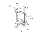
- a notch groove 108 for arranging the conductive member 5 is formed on the outer peripheral surface and the end surface of the motor outer shell 10 (see FIGS. 3 and 5).
- the notch groove 108 formed in the end surface 13 of the motor outer shell 10 extends from the vicinity of the center in the radial direction of the permanent magnet motor 1 to the outer edge portion.
- the notch groove 108 formed on the outer peripheral surface 14 of the motor outer shell 10 is formed so as to extend along the rotation axis direction of the permanent magnet motor 1 so as to be continuous from the notch groove 108 formed on the end surface 13.
- ⁇ Conduction member> When the motor 1 is driven by a PWM type inverter that performs high frequency switching, the neutral point potential of the winding does not become zero, and a voltage called a common mode voltage is generated. Due to this common mode voltage, the stray capacitance inside the motor 1 causes a potential difference (shaft voltage) between the inner rings 334 and 344 of the first bearing 33 and the second bearing 34 and the outer rings 332 and 342, respectively. ..
- Electrolytic corrosion is a phenomenon in which a bearing is damaged by a discharge (electric spark) generated when the axial voltage between the inner rings 334 and 344 of the first bearing 33 and the second bearing 34 and the outer rings 332 and 342 is high.
- electrolytic corrosion occurs in a bearing, scratches on the rolling surface of the bearing cause abnormal noise when the bearing rotates, or the rotation efficiency of the motor is lowered.
- a conduction member that conducts the first bearing accommodating portion 42 in which each of the two bearings is accommodated and the second bearing accommodating portion 43. It is equipped with 5.
- the conductive member 5 is formed by processing, for example, a conductive material (for example, SUS304 of stainless steel) into a band shape or a wire shape.
- the conductive member 5 is formed by bending a steel plate having a thickness of about 0.3 mm, which is punched out in a strip shape, into an L-shape or a U-shape along the outer surfaces of the motor outer shell 10 and the bracket 41 (. See FIGS. 3 and 6).
- the conductive member 5 has a spring characteristic in consideration of attachment to the motor 1.
- the conduction member 5 has the first bearing 33 and the second bearing 33 by conducting the first bearing accommodating portion 42 in which the first bearing 33 is accommodated and the second bearing accommodating portion 43 in which the second bearing 34 is accommodated.
- the potentials of the outer rings 332 and 342 of the bearing 34 can be set to the same potential, and the occurrence of electrolytic corrosion can be suppressed by making the potential difference between the inner and outer rings of each bearing relatively small.
- the conduction member 5 includes a connection end portion connected to the bearing accommodating portions 42 and 43, an end face side arrangement portion arranged radially extending to the end surface 13 of the outer shell of the motor 1, and an outer peripheral surface 14 of the outer shell of the motor 1. Is provided with an outer peripheral surface side arrangement portion arranged along the rotation axis C direction.
- the conductive member 5 is formed of one strip-shaped member is illustrated, but a plurality of conductive members may be connected to form the conductive member 5.
- the conductive member 5 As shown in FIGS. It is arranged so as to extend to the inside of the 415. By arranging the conductive member 5 in the notch groove 108, the conductive member 5 does not project to the surface of the outer shell of the motor 1 and the conductive member 5 can be prevented from falling off from the motor 1.
- connection ends at both ends of the conduction member 5 are bent along the tubular connection portion 45 of the resin outer shell, the tubular portion 421 of the bearing house portion 42, and the fitting portion 415 of the bracket 41. For example, it is press-fitted and fixed. As a result, both connecting ends of the conductive member 5 are fixed in contact with each of the flange portion 422 and the fitting portion 415 of the bearing house portion 42, so that the first bearing 33 and the second bearing 34 are brought into contact with each other. It is conducted.
- the means for fixing both ends of the conductive member 5 to the bearing house portion is not limited to the above-mentioned means.
- the connection end portion of the conductive member 5 may be fixed to the bearing house portions 42, 43 by a caulking member (not shown).
- the capacitance (stator capacitance) Cs on the stator 2 side is between the stator 2 and the bracket 41, and the rotor 3 side is between the rotor 3 and the shaft 32.
- Cb2 is present.
- the capacitances Cb1 and Cb2 between the inner ring and the outer ring of each bearing are considered to be smaller than the stator capacitance Cs and the rotor capacitance Cr in consideration of size, mass, material and the like.
- FIG. 8 is a non-grounded bridge type equivalent circuit diagram of the motor 1 with respect to these capacitances.
- the ground capacitance of the stator (stator) 2 is C1
- the ground capacitance of the rotor (rotor) 3 is C2
- the pulse voltage synchronized with the PWM frequency in the high frequency switching of the motor 1 is Vp
- the shaft voltage between the inner ring and the inner ring is
- C1 and C2 have relatively small values and can be approximated to C1 ⁇ C2. Therefore, the condition for minimizing the shaft voltage
- is Cr Cs.
- the capacitance of Cs can be easily increased and the capacitance of Cs can be brought closer to the capacitance of Cr. ..
- can be reduced to suppress the occurrence of electrolytic corrosion in the bearing.
- a conductive sheet (conductive member) 6 is attached to the outer peripheral surface 14 (surface) of the motor outer shell 10 so as to cover at least a part of the conductive member 5. At least a part of the conductive sheet 6 faces the stator core 21 in the radial direction via the resin motor outer shell 10. In the present embodiment, the conductive sheet 6 is adhered to the motor outer shell 10 in a state of being in contact with the conductive member 5 (see FIGS. 5, 14 and the like).
- the seat 6 and the stator core 21 function as a capacitor (capacitance), and the capacitance Cs on the stator 2 side can be increased. That is, when the conductive sheet 6 faces the stator core 21 of the conductor with the resin outer shell (motor outer shell) 10 of the insulator in between, charges are accumulated between the two conductors of the sheet 6 and the stator core 21. ..
- the stator capacitance Cs depends on the presence or absence of the sheet 6. It is known that there is almost no change in. For example, when the conductive sheet 6 attached to the outer peripheral surface 14 of the motor outer shell 10 is arranged 1 cm away from the conductive member 5 in the circumferential direction of the motor, the stator capacitance Cs does not increase due to the sheet 6. It is presumed that this is because when the conductive sheet 6 does not cover the conductive member 5 at all, the conductive sheet 6 is in a state of being electrically floated, so that the conductive sheet 6 does not function as a capacitor. Will be done.
- the size of the stator capacitance Cs that increases when the conductive sheet 6 covers at least a part of the conductive member 5 is the size of the area of the region overlapping the stator core 21 of the sheet 6 in the radial direction. It is estimated that it is roughly proportional to the static electricity. Therefore, in the present embodiment, the seat 6 is arranged in the region where the stator core 21 is projected in the outer diameter direction on the surface of the motor outer shell 10 (see FIG. 7). As a result, the capacitance Cs on the stator 2 side can be appropriately adjusted so that the sheet 6 contributes to the increase in the stator capacitance Cs without waste.
- the sheet 6 is formed so that the angle ⁇ in the circumferential direction formed by the sheet 6 attached on the outer peripheral surface 14 of the motor outer shell 10 around the rotation axis C is, for example, about 30 °. (See Figures 5 and 7 etc.).
- This angle ⁇ can be arbitrarily changed according to the desired capacitance Cs.
- the dimensions of the seat 6 in the rotation axis C direction can be arbitrarily changed.
- the sheet 6 has a rectangular shape and is arranged so that the long sides intersect the axis direction of the rotation axis C.
- the long sides of the sheet 6 are arranged orthogonal to the axial direction of the rotation axis C.
- the shape of the sheet 6 can be arbitrarily changed such as a rhombus, a circle, and a square.
- the conductive sheet 6 is formed by depositing a metal such as aluminum on the front surface of a thin plate (sheet) made of PET material and providing an adhesive surface on the back surface.
- the sheet 6 is formed by adhering a metal to a thin resin plate.
- the adhesive surface of the conductive sheet 6 is formed of a conductive adhesive.
- the adhesive surface of the conductive sheet 6 may be formed of an insulating material, and the conductive portion (metal or the like) of the sheet 6 and the stator core 21 are sandwiched between the insulating material (resin outer shell, adhesive surface). By being close to each other, it functions as a capacitor (capacitance).
- the sheet 6 may be formed of a sheet metal having a thickness of about 0.2 mm and may be fastened to the motor outer shell 10 with screws or the like.
- a rated name plate 7 may be attached to the outer peripheral surface 14 of the motor outer shell 10 separately from the seat 6 (see FIGS. 3, 5, and 7).
- the rating plate 7 is a name plate (label) on which values (rated values) such as specifications, performance, and usage limits under specified conditions are described for equipment, devices, parts, and the like.
- the rated name plate 7 may be made of the same material as the sheet 6. As a result, the material used as the rated name plate 7 can be diverted to the sheet 6, or the material used as the sheet 6 can be diverted to the rated name plate 7, and the manufacturing cost can be reduced.
- the rated name plate 7 may be used as the sheet 6 as another embodiment in which the rated name plate 7 is formed of the same material as the sheet 6. That is, the rated name plate 7 made of a conductive material may be attached to the position of the sheet 6 in FIG. 7. As a result, since the rated name plate 7 functions as the seat 6 of the present invention, it is not necessary to separately prepare the seat 6, and the manufacturing cost of the permanent magnet motor 1 can be reduced.
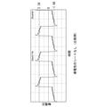
- FIG. 9 shows the output waveform of the shaft voltage in the motor (comparative example) in the state where the conductive sheet 6 is not attached
- FIG. 10 shows the conductive sheet 6 attached to the electric motor in the comparative example. It is an output waveform of the shaft voltage in the motor 1 of an Example.
- the sheet 6 is a rectangular thin plate having a width of 3.0 cm, a depth (height) of 2.0 cm, and a thickness of about 0.05 mm.
- the driving conditions of the motor were such that the applied voltage was DC380V and the rotation speed was 1,520 rotations / min.
- the maximum value of the shaft voltage on the + side is 2.34V and the maximum value on the-side is -1.68V in the comparative example (without sheet 6), whereas the maximum value on the-side is -1.68V, whereas the maximum value on the-side is -1.68V. Yes), the maximum value on the + side of the shaft voltage is 1.48V, and the maximum value on the-side is -0.77V. That is, it can be seen that by attaching the conductive sheet 6 to the motor 1, the maximum value of the shaft voltage can be reduced to about half as compared with the case where the conductive sheet 6 is not attached.
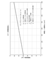
- FIG. 11 is a graph showing the stator capacitance Cs with respect to the area change of the conductive sheet 6. As shown in this figure, the stator capacitance Cs is linear with respect to changes in the area ACS of the conductive sheet 6.
- stator capacitance Cs is [Equation 1]
- Cs C 0 + k ⁇ A CS / d
- C 0 is the stator capacitance when there is no conductive sheet 6
- k is a coefficient determined by the shape of the motor such as the bracket 41
- ⁇ is the resin outer shell 10 existing between the sheet 6 and the stator core 21.
- the dielectric constant, ACS is the area of the conductive sheet 6
- d is the distance between the opposing sheet 6 and the stator core 21 via the resin outer shell 10. That is, the stator capacitance Cs can be easily adjusted by changing the area ACS of the conductive sheet 6.
- FIG. 12 is a perspective view showing a part of the electric motor 1 without the conductive sheet 6 according to the present invention.
- the resin outer shell 10 is transmitted and displayed.
- the stator capacitance Cs may be further adjusted by changing the width W of the conductive member 5.
- Table 1 and FIG. 13 show the stator capacitance Cs with respect to the change in the width W of the conductive member 5.
- stator capacitance Cs increases approximately linearly. That is, the stator capacitance Cs can also be increased (+4.75pF) by increasing the width W of the conductive member 5 (for example, changing from 5.0 mm to 10 mm).
- FIG. 14 is a partial side perspective view showing the electric motor 1 provided with the conductive sheet 6 according to the present invention. That is, No. 1 in Table 1.
- the motor 1 of the embodiment has a conductive sheet 6 attached to the motor of 1 (comparative example).
- Table 2 and FIG. 15 show the stator capacitance Cs with respect to the change in the area ACS of the rectangular conductive sheet 6.
- the case where the area ACS of the seat 6 is changed by changing the height H of the seat 6 is illustrated.
- Table 2 instead of the width T (mm) which is the length dimension, the angle ⁇ (°) formed by the sheet 6 attached on the outer peripheral surface 14 of the motor outer shell 10 around the rotation axis C (FIG. 7).
- 14 is the angle formed by the two line segments connecting both ends of the sheet 6 in the circumferential direction and the rotation axis C) as a representative value.
- r 46 (mm).
- the motor 1 (No. 7 to No. 9 in Table 2) of the embodiment provided with the conductive sheet 6 includes the conductive sheet 6.
- the stator capacitance Cs can be made larger than that of the motor of the comparative example (No. 1 in Table 1). Further, it can be seen that the amount of increase in the stator capacitance Cs due to the provision of the conductive sheet 6 is substantially linear with the amount of increase in the area ACS of the conductive sheet 6. Therefore, in the electric motor 1 of the embodiment, the stator capacitance Cs can be easily adjusted by changing the area ACS of the conductive sheet 6.
- the area ACS of the seat 6 is changed by changing the height H of the seat 6 (the length of the seat 6 in the rotation axis C direction of the motor 1), but the conductive seat.
- the area ACS of the seat 6 may be changed by changing the width T (the length of the seat 6 in the circumferential direction of the motor 1) of 6.
- a conductive sheet that covers at least a part of the conductive member is attached to the outer peripheral surface 14 (surface) of the outer peripheral surface of the motor. Therefore, when the conductive sheet and the stator core face each other via the resin outer shell, the conductive sheet functions as a capacitor and adjusts the capacitance (increases the capacitance Cs on the stator side). can.
- the capacitance on the stator side can be easily adjusted by changing the area of the conductive sheet. As a result, the balance between the capacitance on the stator side and the capacitance on the rotor side can be easily adjusted, and the shaft voltage can be reduced to suppress the occurrence of electrolytic corrosion.
Landscapes
- Engineering & Computer Science (AREA)
- Power Engineering (AREA)
- Motor Or Generator Frames (AREA)
Abstract
Description
この電食の発生を抑制する従来技術として、電動機のステータ側の静電容量とロータ側の静電容量とが概ね等しくなるよう調整することで、軸電圧を小さくして電食の発生を抑制したものが知られている(特許文献1)。
特許文献1では、ロータコアを内側コアと外側コアとに分割し、それらの間に誘電体(絶縁体)層を設けることで、静電容量が調整される。
図1~6は、本実施形態における電動機1の構成を説明する図である。これらの図に示すように、この電動機1は、例えば、ブラシレスDCモータである。この電動機1は、図示しないが、例えば空気調和機の室外機に搭載される送風ファンを回転駆動するために用いられる。
以下では、回転磁界を発生する円筒状の固定子2の径方向の内側に、永久磁石部31を有する円柱状の回転子3を回転可能に配置したインナーロータ型の永久磁石電動機1を例に説明する。
回転子3は、図6に示すように、固定子2の固定子鉄心21の内周側に所定の空隙(ギャップ)を持って回転自在に配置されている。この回転子3は、固定子鉄心21に対向する外周面に環状に永久磁石31を配置した表面磁石型である。
永久磁石31は、図1および6に示すように、外周側鉄心32、絶縁部材33および内周側鉄心35を介してシャフト32の周りに固定されている。このシャフト32は、第1軸受33および第2軸受34によって支持されている。そして、第1軸受33が収容される後述の軸受収容部42(ブラケット41)、および、第2軸受34が収容される後述の第2軸受収容部43のそれぞれが、樹脂製のモータ外郭10に固定されることで、回転子3が回転自在に支持されている。
なお、内周側鉄心35は、この貫通穴と内周側鉄心35の外周面との間に、重量を軽くするための肉抜き用の複数の貫通穴(図示せず)を備えてもよい。これらの複数の貫通穴は、中心軸方向から見て、貫通穴が形成された内周側鉄心35の形状がスポーク状になるように、円周方向に等間隔に配置される。
この絶縁部材33を設けることで、外周側鉄心32と内周側鉄心35の間の静電容量(固定子2の巻線とシャフト32の間の静電容量の一部)をより小さくできる。このとき、外周側鉄心32と内周側鉄心35の間の静電容量は、絶縁部材33の厚み(径方向の長さ)に依存している。回転子3側の静電容量が絶縁部材33の厚みによって調整されている電動機1は、固定子2側の静電容量と回転子3側の静電容量を合わせることで、内輪334、344側と外輪332、342側との間の電位差が小さくなるように調整されており、これによって軸受の電食を防止している。
なお、本実施例では、回転子3の回転子鉄心は、内周側鉄心32と外周側鉄心35の2つの円筒状の鉄心を絶縁部材33で連結する構造としたが、回転子鉄心の構造はこれに限定されない。例えば、回転子鉄心は、絶縁部材33を備えずともよく、1つの円筒状の鉄心から形成されていてもよい。
すなわち、モータ外郭10は、固定子鉄心21と巻線とを備えた固定子2を覆っており、回転子3を内部に収容する。固定子2は、回転子3の外周側(永久磁石電動機1の径方向における外側)に配置される。また、固定子2の固定子鉄心21は、同固定子鉄心21の有するティース部が回転子3の永久磁石部31と径方向で対向するように配置されている。換言すれば、固定子2は、回転子3の備える環状の永久磁石部31が固定子2の固定子鉄心21に径方向で対向するように配置されている。
モータ外郭10は、例えばBMC(Bulk Molding Compound:不飽和ポリエステル樹脂)樹脂で形成される。なお、モータ外郭10は、全体が樹脂等の絶縁性材料から形成される必要はなく、一部が導電性材料の金属で形成されてもよい。また、本実施例ではモータ外郭10の外観が円柱状である場合を例示したが、モータ外郭10の外観が四角柱状や六角柱状であってもよい。
また、第1軸受33が後述する第1軸受収容部42に収容(保持)され、第2軸受34が後述する第2軸受収容部43に収容(保持)されることで、回転子3が回転自在に支持されている。第1軸受収容部42および第2軸受収容部43は、例えばクロムニッケル系ステンレス鋼の磁性体で形成されている。
図6に示すように、第1軸受33は、同第1軸受33の内輪334側がシャフト32の一端側(反出力側)に固定されている。第2軸受34は、同第2軸受34の内輪344側がシャフト32の他端側(出力側)に固定されている。第1軸受33と第2軸受34(一対のベアリング)は協働して、シャフト32およびシャフト32に連結される回転子3を回転自在に支持している。
このブラケット41は、モータ外郭10の開口部Oを覆う蓋として、モータ外郭10の出力側の端部に圧着、ねじ止めなどされて取り付けられる。なお、モータ外郭10の開口部Oは、反出力側に向けて開口するようにしてもよい。この場合、ブラケット41は、シャフト32の出力側でなく、シャフト32の反出力側に配置される。
第1軸受収容部42は、回転子3の径方向において、環状の永久磁石部31よりも内側(内径側)に配置されている。非磁性体である樹脂製のモータ外郭10の端面部13の内径側には、第1軸受収容部42に接続される接続部45を有する(図6参照)。
冠部423は、第1軸受33の回転軸C方向の他端側を覆う。円環状のフランジ部422の外周縁は、永久磁石部31よりも回転子3の径方向における内側(内周側)に位置している。換言すると、第1軸受収容部42は、回転子3の回転軸C方向から見て、永久磁石部31と重ならないように形成されている。
すなわち、外郭10において、第1軸受収容部42のフランジ部422の外周縁部は、樹脂製の接続部45によって覆われている。
第2軸受収容部43は、第1軸受収容部42と同様の形状に形成され、第2軸受34の外輪342側を径方向から保持する筒状部431と、筒状部431の回転軸C方向の他端部から径方向の内側へと延びる冠部433と、を有する。
カバー本体414は、全体が概ね円板形状に形成されている。嵌合部415は、図6に示すように、カバー本体414の外周縁部に配置された円環形状の突起として形成されている。嵌合部415がモータ外郭10の出力側の端部(図6におけるモータ外郭10の上端面)に回転軸C方向から嵌合されることで、図3(A)および5に示すように、モータ外郭10とブラケット41とが軸合わせされるとともに、第2軸受34がブラケット41に設けられた第2軸受収容部43に収容される。
電動機1は、高周波スイッチングを行うPWM方式のインバータで駆動される場合に、巻線の中性点電位が零にならず、コモンモード電圧と呼ばれる電圧が発生する。このコモンモード電圧に起因して、電動機1の内部の浮遊容量によって、第1軸受33および第2軸受34の各々の内輪334、344と外輪332、342との間に電位差(軸電圧)を生じる。
本実施例の電動機1は、この軸受での電食の発生を抑制するために、2つの軸受のそれぞれが収容される第1軸受収容部42と第2軸受収容部43とを導通させる導通部材5を備えている。
導通部材5は、第1軸受33が収容される第1軸受収容部42と、第2軸受34が収容される第2軸受収容部43と、を導通させることにより、第1軸受33と第2軸受34の各々の外輪332、342の電位を同電位とすることができ、各軸受の内外輪間の電位差を相対的に小さくすることで電食の発生を抑制できる。
導通部材5が切り込み溝部108に配置されることにより、導通部材5が電動機1の外郭の表面に突出せず、電動機1から導通部材5が脱落するのを防止できる。
これにより、導通部材5の両接続端部がベアリングハウス部42のフランジ部422および嵌合部415のそれぞれに当接した状態で固定されることにより、第1軸受33と第2軸受34とが導通される。
ここで、固定子(ステータ)2の対地静電容量をC1、回転子(ロータ)3の対地静電容量をC2、電動機1の高周波スイッチングにおけるPWM周波数に同期したパルス電圧をVp、軸受の外輪と内輪との間の軸電圧を|Vs-Vr|とする。
このとき、軸電圧|Vs-Vr|が最小となる条件は、Cs・C2=Cr・C1である。また、PWM周波数ωでの固定子2および回転子3の対地インピーダンスをそれぞれ、Z1=(1/ωC1)、Z2=(1/ωC2)とすると、対地インピーダンスは、非常に大きな値をとるので、C1およびC2は相対的に小さな値になり、C1≒C2に近似できる。したがって、軸電圧|Vs-Vr|を最小化する条件は、Cr=Csである。本実施形態では、回転子3側の静電容量(ロータ静電容量Cr)が固定子2側の静電容量(ステータ静電容量Cs)よりも大きい状態の永久磁石電動機1、すなわちCr>Csである状態の永久磁石電動機1に、後述する導電性のシート(導電性部材)6を取り付けることで、Csの静電容量を容易に増やして、CsをCrの静電容量に近づけることができる。これにより、軸電圧|Vs-Vr|を小さくして、軸受での電食の発生を抑制することができる。
本実施形態では、シート6は、モータ外郭10の外周面14上に貼り付けられたシート6が回転軸Cまわりで成す周方向の角度θが、例えば30°程度となる長さに形成されている(図5、7等参照)。この角度θは、所望の静電容量Csに応じて任意に変更できる。例えば、シート6は、モータ外郭1の周方向において全周にわたって(θ=360°となるように)延びてもよい。シート6の回転軸C方向の寸法も同様に任意に変更可能である。
本実施形態では、導電性のシート6は、図示しないが、PET素材の薄板(シート)の表面にアルミ等の金属を蒸着し、裏面に接着面を設けて形成される。言い換えれば、シート6は、樹脂製の薄板に金属を付着させて形成される。接着面を有する薄板を用いることにより、シート6を安価に形成するとともに接着により容易にモータ外郭10の曲面状の外周面14に取り付けることができる。本実施例では、導電性のシート6の接着面は、導電性の接着剤で形成されている。なお、導電性のシート6の接着面は絶縁材で形成されていてもよく、シート6の導電部(金属等)とステータコア21とが、間に絶縁材(樹脂外郭、接着面)を介して互いに近接することで、キャパシタ(静電容量)として機能する。
あるいは他の実施形態として、シート6は、厚み0.2mm程度の板金で形成され、ねじ等でモータ外郭10に留められてもよい。
なお、定格銘板7は、シート6と同じ材料で形成されてよい。これにより、定格銘板7として使用していた材料をシート6に転用でき、あるいはシート6として使用していた材料を定格銘板7として転用でき、製造コストを削減することができる。
これら2つの図を比較すると、比較例(シート6なし)における軸電圧は+側の最大値が2.34V、-側の最大値が-1.68Vであるのに対し、実施例(シート6あり)における軸電圧の+側の最大値は1.48V、-側の最大値は-0.77Vとなっている。すなわち、電動機1に導電性のシート6を貼り付けることによって、導電性のシート6を貼り付けない場合に比べて、軸電圧の最大値を半分程度に小さくできていることが分かる。
この図に示されているように、ステータ静電容量Csは、導電性のシート6の面積ACSの変化に対して線形である。
[式1]
Cs=C0+kεACS/d
という関係式で表せる。
ここで、C0は導電性のシート6が無い場合におけるステータ静電容量であり、kはブラケット41などのモータ形状で決まる係数、εはシート6とステータコア21の間に存在する樹脂外郭10の誘電率、ACSは導電性のシート6の面積、dは樹脂外郭10を介して対向するシート6とステータコア21間の距離である。
すなわち、導電性のシート6の面積ACSを変化させることにより、ステータ静電容量Csを容易に調整することができる。
本発明の他の実施形態として、導電性のシート6の他に、導通部材5の幅Wを変化させることによって、ステータ静電容量Csを更に調整してもよい。
この導通部材5の幅Wの変化に対するステータ静電容量Csを表1および図13に示す。

この長方形状の導電性のシート6の面積ACSの変化に対するステータ静電容量Csを、表2および図15に示す。シート6の面積ACSは、シート6の高さ(電動機1の回転軸C方向におけるシート6の長さ)をH、シート6の幅(電動機1の周方向におけるシート6の長さ)をTとしたとき、ACS=T×H(mm2)で求められている。本実施例では、シート6の高さHを変化させることによりシート6の面積ACSを変化させた場合を例示する。なお、表2では、長さ寸法である幅T(mm)の代わりに、モータ外郭10の外周面14上に貼り付けられたシート6が回転軸Cまわりで成す角度θ(°)(図7、14においてシート6の周方向の両端部と回転軸Cとを結んだ2つの線分が成す角度)を代表値として示す。このとき、幅T(mm)は、回転軸Cからモータ外郭10の外周面14までの距離を半径r(mm)としたとき、円周率をπとして、T=π×r×θ/180で求めることができる。本実施例では、r=46(mm)としている。

また、表1および表2より、導電性のシート6を備える実施例のNo.7~No.9のいずれの場合においても、導電性のシート6を備えない比較例であるNo.1よりも、ステータ静電容量Csが増加(+6.10~+10.46pF)していることが分かる。
なお、本実施例では、シート6の高さH(電動機1の回転軸C方向におけるシート6の長さ)を変化させることによりシート6の面積ACSを変化させているが、導電性のシート6の幅T(電動機1の周方向におけるシート6の長さ)を変化させることでシート6の面積ACSを変化させるようにしてもよい。
これにより、ステータ側の静電容量とロータ側の静電容量との間のバランスを容易に調整することができ、軸電圧を低減して電食の発生を抑制することができる。
10…モータ外郭(樹脂外郭)
13…端面部
105…切り込み溝部
2…固定子
21…ステータコア
3…回転子
32…シャフト
33…第1軸受
34…第2軸受
41…ブラケット
44…端面部
5…導通部材
6…導電性のシート(導電性部材)
7…定格銘板
C…回転軸
Claims (8)
- 回転子と、
前記回転子の回転軸に沿って配置されて前記回転子が固定されたシャフトと、
前記シャフトの一端側に配置された第1軸受と、
前記シャフトの他端側に配置された第2軸受と、
前記回転子の外周側に配置されたステータコアと、
前記ステータコアを覆う樹脂外郭と、
前記第1軸受および前記第2軸受のそれぞれが備える外輪同士を電気的に接続する導通部材と、を備える電動機であって、
前記樹脂外郭の表面には、前記導通部材の少なくとも一部を覆う導電性部材が取り付けられる
電動機。 - 請求項1に記載の電動機であって、
前記導電性部材は、同導電性部材の少なくとも一部が、前記樹脂外郭を介して前記ステータコアと径方向で対向する
電動機。 - 請求項1または2に記載の電動機であって、
前記導電性部材は、前記導通部材に接触している
電動機。 - 請求項1~3のいずれか1項に記載の電動機であって、
前記導電性部材は、樹脂製の薄板に金属を付着させて形成される
電動機。 - 請求項1~4のいずれか1項に記載の電動機であって、
前記導電性部材は、接着面を有する
電動機。 - 請求項1~5のいずれか1項に記載の電動機であって、
前記導電性部材は、前記樹脂外郭の表面において前記ステータコアを外径方向に投影した領域内に配置される
電動機。 - 請求項1~6のいずれか1項に記載の電動機であって、
前記導電性部材は、長方形状であり、長辺が前記回転軸の軸方向に交差するように配置される
電動機。 - 請求項1~7のいずれか1項に記載の電動機であって、
前記樹脂外郭の表面には、定格銘板が取り付けられ、
前記定格銘板は、前記導電性部材と同じ材料で形成される
電動機。
Applications Claiming Priority (2)
| Application Number | Priority Date | Filing Date | Title |
|---|---|---|---|
| JP2020-146439 | 2020-08-31 | ||
| JP2020146439A JP6984704B1 (ja) | 2020-08-31 | 2020-08-31 | 電動機 |
Publications (1)
| Publication Number | Publication Date |
|---|---|
| WO2022045340A1 true WO2022045340A1 (ja) | 2022-03-03 |
Family
ID=79193342
Family Applications (1)
| Application Number | Title | Priority Date | Filing Date |
|---|---|---|---|
| PCT/JP2021/031814 Ceased WO2022045340A1 (ja) | 2020-08-31 | 2021-08-31 | 電動機 |
Country Status (2)
| Country | Link |
|---|---|
| JP (1) | JP6984704B1 (ja) |
| WO (1) | WO2022045340A1 (ja) |
Citations (6)
| Publication number | Priority date | Publication date | Assignee | Title |
|---|---|---|---|---|
| JP2007116839A (ja) * | 2005-10-20 | 2007-05-10 | Nidec Shibaura Corp | モータ |
| JP2012210064A (ja) * | 2011-03-30 | 2012-10-25 | Fujitsu General Ltd | モールドモーター |
| JP2014107998A (ja) * | 2012-11-29 | 2014-06-09 | Panasonic Corp | 電動機 |
| JP2015126583A (ja) * | 2013-12-26 | 2015-07-06 | 日本電産テクノモータ株式会社 | インナーロータ型モータ |
| CN112366878A (zh) * | 2019-07-26 | 2021-02-12 | 广东威灵电机制造有限公司 | 无刷电机及电器设备 |
| CN112366897A (zh) * | 2019-07-26 | 2021-02-12 | 广东威灵电机制造有限公司 | 无刷电机及电器设备 |
-
2020
- 2020-08-31 JP JP2020146439A patent/JP6984704B1/ja active Active
-
2021
- 2021-08-31 WO PCT/JP2021/031814 patent/WO2022045340A1/ja not_active Ceased
Patent Citations (6)
| Publication number | Priority date | Publication date | Assignee | Title |
|---|---|---|---|---|
| JP2007116839A (ja) * | 2005-10-20 | 2007-05-10 | Nidec Shibaura Corp | モータ |
| JP2012210064A (ja) * | 2011-03-30 | 2012-10-25 | Fujitsu General Ltd | モールドモーター |
| JP2014107998A (ja) * | 2012-11-29 | 2014-06-09 | Panasonic Corp | 電動機 |
| JP2015126583A (ja) * | 2013-12-26 | 2015-07-06 | 日本電産テクノモータ株式会社 | インナーロータ型モータ |
| CN112366878A (zh) * | 2019-07-26 | 2021-02-12 | 广东威灵电机制造有限公司 | 无刷电机及电器设备 |
| CN112366897A (zh) * | 2019-07-26 | 2021-02-12 | 广东威灵电机制造有限公司 | 无刷电机及电器设备 |
Also Published As
| Publication number | Publication date |
|---|---|
| JP2022041317A (ja) | 2022-03-11 |
| JP6984704B1 (ja) | 2021-12-22 |
Similar Documents
| Publication | Publication Date | Title |
|---|---|---|
| US11165312B2 (en) | Axial-gap dynamo-electric machine | |
| JP5965228B2 (ja) | アキシャルギャップ型回転電機 | |
| CN109314423B (zh) | 永磁电动机 | |
| EP3148057B1 (en) | Electric motor | |
| WO2017145274A1 (ja) | アキシャルギャップ型回転電機 | |
| JP5910674B2 (ja) | 電動機 | |
| US12231018B2 (en) | Motor and electric appliance | |
| JP6984704B1 (ja) | 電動機 | |
| JP2016208644A (ja) | ブラシ付き回転電機 | |
| GB2281819A (en) | Locating and securing commutator segments | |
| JP2008043124A (ja) | 磁石発電機 | |
| WO2003043164A1 (fr) | Machine dynamoelectrique | |
| US20130127305A1 (en) | Electric drive unit | |
| US20230124788A1 (en) | Rotary Transformer | |
| WO2021200475A1 (ja) | 永久磁石電動機 | |
| CN116317218B (zh) | 定子结构以及具有其的电机 | |
| JP7415751B2 (ja) | 電動機 | |
| KR20140145996A (ko) | 전기 모터 | |
| JP6834294B2 (ja) | 永久磁石電動機 | |
| JP7337001B2 (ja) | アキシャルギャップ型回転電機 | |
| JP7415774B2 (ja) | 電動機 | |
| JP2018074693A (ja) | 回転電機のステータ | |
| US20230155444A1 (en) | Electric motor | |
| WO2021255960A1 (ja) | アキシャルギャップ型回転電機 | |
| JP2012044848A (ja) | 整流子及び直流モータ |
Legal Events
| Date | Code | Title | Description |
|---|---|---|---|
| 121 | Ep: the epo has been informed by wipo that ep was designated in this application |
Ref document number: 21861761 Country of ref document: EP Kind code of ref document: A1 |
|
| WWE | Wipo information: entry into national phase |
Ref document number: 202317023238 Country of ref document: IN |
|
| NENP | Non-entry into the national phase |
Ref country code: DE |
|
| 122 | Ep: pct application non-entry in european phase |
Ref document number: 21861761 Country of ref document: EP Kind code of ref document: A1 |
|
| WWG | Wipo information: grant in national office |
Ref document number: 202317023238 Country of ref document: IN |