WO2022044944A1 - Vehicle - Google Patents
Vehicle Download PDFInfo
- Publication number
- WO2022044944A1 WO2022044944A1 PCT/JP2021/030336 JP2021030336W WO2022044944A1 WO 2022044944 A1 WO2022044944 A1 WO 2022044944A1 JP 2021030336 W JP2021030336 W JP 2021030336W WO 2022044944 A1 WO2022044944 A1 WO 2022044944A1
- Authority
- WO
- WIPO (PCT)
- Prior art keywords
- vehicle
- pair
- frame
- vehicle according
- wheels
- Prior art date
Links
- 210000002683 foot Anatomy 0.000 description 11
- 238000010586 diagram Methods 0.000 description 8
- 230000004048 modification Effects 0.000 description 6
- 238000012986 modification Methods 0.000 description 6
- 230000000694 effects Effects 0.000 description 5
- 239000000463 material Substances 0.000 description 3
- 125000002066 L-histidyl group Chemical group [H]N1C([H])=NC(C([H])([H])[C@](C(=O)[*])([H])N([H])[H])=C1[H] 0.000 description 2
- 210000003423 ankle Anatomy 0.000 description 2
- 230000005484 gravity Effects 0.000 description 2
- QNRATNLHPGXHMA-XZHTYLCXSA-N (r)-(6-ethoxyquinolin-4-yl)-[(2s,4s,5r)-5-ethyl-1-azabicyclo[2.2.2]octan-2-yl]methanol;hydrochloride Chemical compound Cl.C([C@H]([C@H](C1)CC)C2)CN1[C@@H]2[C@H](O)C1=CC=NC2=CC=C(OCC)C=C21 QNRATNLHPGXHMA-XZHTYLCXSA-N 0.000 description 1
- 229920001875 Ebonite Polymers 0.000 description 1
- HBBGRARXTFLTSG-UHFFFAOYSA-N Lithium ion Chemical compound [Li+] HBBGRARXTFLTSG-UHFFFAOYSA-N 0.000 description 1
- 230000009194 climbing Effects 0.000 description 1
- 230000001771 impaired effect Effects 0.000 description 1
- 238000009434 installation Methods 0.000 description 1
- 230000002452 interceptive effect Effects 0.000 description 1
- 210000003127 knee Anatomy 0.000 description 1
- 229910001416 lithium ion Inorganic materials 0.000 description 1
- 230000007935 neutral effect Effects 0.000 description 1
- 230000002093 peripheral effect Effects 0.000 description 1
- 230000000284 resting effect Effects 0.000 description 1
- 238000005096 rolling process Methods 0.000 description 1
- 239000007858 starting material Substances 0.000 description 1
- 239000011800 void material Substances 0.000 description 1
Images


Classifications
-
- B—PERFORMING OPERATIONS; TRANSPORTING
- B62—LAND VEHICLES FOR TRAVELLING OTHERWISE THAN ON RAILS
- B62K—CYCLES; CYCLE FRAMES; CYCLE STEERING DEVICES; RIDER-OPERATED TERMINAL CONTROLS SPECIALLY ADAPTED FOR CYCLES; CYCLE AXLE SUSPENSIONS; CYCLE SIDE-CARS, FORECARS, OR THE LIKE
- B62K5/00—Cycles with handlebars, equipped with three or more main road wheels
- B62K5/02—Tricycles
- B62K5/027—Motorcycles with three wheels
-
- B—PERFORMING OPERATIONS; TRANSPORTING
- B60—VEHICLES IN GENERAL
- B60L—PROPULSION OF ELECTRICALLY-PROPELLED VEHICLES; SUPPLYING ELECTRIC POWER FOR AUXILIARY EQUIPMENT OF ELECTRICALLY-PROPELLED VEHICLES; ELECTRODYNAMIC BRAKE SYSTEMS FOR VEHICLES IN GENERAL; MAGNETIC SUSPENSION OR LEVITATION FOR VEHICLES; MONITORING OPERATING VARIABLES OF ELECTRICALLY-PROPELLED VEHICLES; ELECTRIC SAFETY DEVICES FOR ELECTRICALLY-PROPELLED VEHICLES
- B60L53/00—Methods of charging batteries, specially adapted for electric vehicles; Charging stations or on-board charging equipment therefor; Exchange of energy storage elements in electric vehicles
- B60L53/30—Constructional details of charging stations
- B60L53/31—Charging columns specially adapted for electric vehicles
-
- B—PERFORMING OPERATIONS; TRANSPORTING
- B62—LAND VEHICLES FOR TRAVELLING OTHERWISE THAN ON RAILS
- B62J—CYCLE SADDLES OR SEATS; AUXILIARY DEVICES OR ACCESSORIES SPECIALLY ADAPTED TO CYCLES AND NOT OTHERWISE PROVIDED FOR, e.g. ARTICLE CARRIERS OR CYCLE PROTECTORS
- B62J1/00—Saddles or other seats for cycles; Arrangement thereof; Component parts
- B62J1/08—Frames for saddles; Connections between saddle frames and seat pillars; Seat pillars
-
- B—PERFORMING OPERATIONS; TRANSPORTING
- B62—LAND VEHICLES FOR TRAVELLING OTHERWISE THAN ON RAILS
- B62J—CYCLE SADDLES OR SEATS; AUXILIARY DEVICES OR ACCESSORIES SPECIALLY ADAPTED TO CYCLES AND NOT OTHERWISE PROVIDED FOR, e.g. ARTICLE CARRIERS OR CYCLE PROTECTORS
- B62J25/00—Foot-rests; Knee grips; Passenger hand-grips
- B62J25/04—Floor-type foot rests
-
- B—PERFORMING OPERATIONS; TRANSPORTING
- B62—LAND VEHICLES FOR TRAVELLING OTHERWISE THAN ON RAILS
- B62J—CYCLE SADDLES OR SEATS; AUXILIARY DEVICES OR ACCESSORIES SPECIALLY ADAPTED TO CYCLES AND NOT OTHERWISE PROVIDED FOR, e.g. ARTICLE CARRIERS OR CYCLE PROTECTORS
- B62J43/00—Arrangements of batteries
- B62J43/10—Arrangements of batteries for propulsion
- B62J43/16—Arrangements of batteries for propulsion on motorcycles or the like
-
- B—PERFORMING OPERATIONS; TRANSPORTING
- B62—LAND VEHICLES FOR TRAVELLING OTHERWISE THAN ON RAILS
- B62J—CYCLE SADDLES OR SEATS; AUXILIARY DEVICES OR ACCESSORIES SPECIALLY ADAPTED TO CYCLES AND NOT OTHERWISE PROVIDED FOR, e.g. ARTICLE CARRIERS OR CYCLE PROTECTORS
- B62J43/00—Arrangements of batteries
- B62J43/20—Arrangements of batteries characterised by the mounting
-
- B—PERFORMING OPERATIONS; TRANSPORTING
- B62—LAND VEHICLES FOR TRAVELLING OTHERWISE THAN ON RAILS
- B62K—CYCLES; CYCLE FRAMES; CYCLE STEERING DEVICES; RIDER-OPERATED TERMINAL CONTROLS SPECIALLY ADAPTED FOR CYCLES; CYCLE AXLE SUSPENSIONS; CYCLE SIDE-CARS, FORECARS, OR THE LIKE
- B62K21/00—Steering devices
- B62K21/02—Front wheel forks or equivalent, e.g. single tine
-
- B—PERFORMING OPERATIONS; TRANSPORTING
- B62—LAND VEHICLES FOR TRAVELLING OTHERWISE THAN ON RAILS
- B62K—CYCLES; CYCLE FRAMES; CYCLE STEERING DEVICES; RIDER-OPERATED TERMINAL CONTROLS SPECIALLY ADAPTED FOR CYCLES; CYCLE AXLE SUSPENSIONS; CYCLE SIDE-CARS, FORECARS, OR THE LIKE
- B62K3/00—Bicycles
- B62K3/002—Bicycles without a seat, i.e. the rider operating the vehicle in a standing position, e.g. non-motorized scooters; non-motorized scooters with skis or runners
-
- B—PERFORMING OPERATIONS; TRANSPORTING
- B62—LAND VEHICLES FOR TRAVELLING OTHERWISE THAN ON RAILS
- B62K—CYCLES; CYCLE FRAMES; CYCLE STEERING DEVICES; RIDER-OPERATED TERMINAL CONTROLS SPECIALLY ADAPTED FOR CYCLES; CYCLE AXLE SUSPENSIONS; CYCLE SIDE-CARS, FORECARS, OR THE LIKE
- B62K5/00—Cycles with handlebars, equipped with three or more main road wheels
- B62K5/02—Tricycles
- B62K5/06—Frames for tricycles
-
- B—PERFORMING OPERATIONS; TRANSPORTING
- B62—LAND VEHICLES FOR TRAVELLING OTHERWISE THAN ON RAILS
- B62K—CYCLES; CYCLE FRAMES; CYCLE STEERING DEVICES; RIDER-OPERATED TERMINAL CONTROLS SPECIALLY ADAPTED FOR CYCLES; CYCLE AXLE SUSPENSIONS; CYCLE SIDE-CARS, FORECARS, OR THE LIKE
- B62K5/00—Cycles with handlebars, equipped with three or more main road wheels
- B62K5/10—Cycles with handlebars, equipped with three or more main road wheels with means for inwardly inclining the vehicle body on bends
-
- B—PERFORMING OPERATIONS; TRANSPORTING
- B60—VEHICLES IN GENERAL
- B60K—ARRANGEMENT OR MOUNTING OF PROPULSION UNITS OR OF TRANSMISSIONS IN VEHICLES; ARRANGEMENT OR MOUNTING OF PLURAL DIVERSE PRIME-MOVERS IN VEHICLES; AUXILIARY DRIVES FOR VEHICLES; INSTRUMENTATION OR DASHBOARDS FOR VEHICLES; ARRANGEMENTS IN CONNECTION WITH COOLING, AIR INTAKE, GAS EXHAUST OR FUEL SUPPLY OF PROPULSION UNITS IN VEHICLES
- B60K1/00—Arrangement or mounting of electrical propulsion units
- B60K1/04—Arrangement or mounting of electrical propulsion units of the electric storage means for propulsion
- B60K2001/0455—Removal or replacement of the energy storages
-
- B—PERFORMING OPERATIONS; TRANSPORTING
- B60—VEHICLES IN GENERAL
- B60L—PROPULSION OF ELECTRICALLY-PROPELLED VEHICLES; SUPPLYING ELECTRIC POWER FOR AUXILIARY EQUIPMENT OF ELECTRICALLY-PROPELLED VEHICLES; ELECTRODYNAMIC BRAKE SYSTEMS FOR VEHICLES IN GENERAL; MAGNETIC SUSPENSION OR LEVITATION FOR VEHICLES; MONITORING OPERATING VARIABLES OF ELECTRICALLY-PROPELLED VEHICLES; ELECTRIC SAFETY DEVICES FOR ELECTRICALLY-PROPELLED VEHICLES
- B60L2200/00—Type of vehicles
- B60L2200/22—Microcars, e.g. golf cars
-
- B—PERFORMING OPERATIONS; TRANSPORTING
- B60—VEHICLES IN GENERAL
- B60L—PROPULSION OF ELECTRICALLY-PROPELLED VEHICLES; SUPPLYING ELECTRIC POWER FOR AUXILIARY EQUIPMENT OF ELECTRICALLY-PROPELLED VEHICLES; ELECTRODYNAMIC BRAKE SYSTEMS FOR VEHICLES IN GENERAL; MAGNETIC SUSPENSION OR LEVITATION FOR VEHICLES; MONITORING OPERATING VARIABLES OF ELECTRICALLY-PROPELLED VEHICLES; ELECTRIC SAFETY DEVICES FOR ELECTRICALLY-PROPELLED VEHICLES
- B60L2200/00—Type of vehicles
- B60L2200/24—Personal mobility vehicles
-
- B—PERFORMING OPERATIONS; TRANSPORTING
- B60—VEHICLES IN GENERAL
- B60Y—INDEXING SCHEME RELATING TO ASPECTS CROSS-CUTTING VEHICLE TECHNOLOGY
- B60Y2200/00—Type of vehicle
- B60Y2200/10—Road Vehicles
- B60Y2200/12—Motorcycles, Trikes; Quads; Scooters
- B60Y2200/126—Scooters
-
- B—PERFORMING OPERATIONS; TRANSPORTING
- B62—LAND VEHICLES FOR TRAVELLING OTHERWISE THAN ON RAILS
- B62K—CYCLES; CYCLE FRAMES; CYCLE STEERING DEVICES; RIDER-OPERATED TERMINAL CONTROLS SPECIALLY ADAPTED FOR CYCLES; CYCLE AXLE SUSPENSIONS; CYCLE SIDE-CARS, FORECARS, OR THE LIKE
- B62K2204/00—Adaptations for driving cycles by electric motor
Definitions
- the present invention relates to a vehicle having front wheels and rear wheels.
- Patent Document 1 an electric three-wheeled vehicle having a single front wheel and a pair of left and right rear wheels has been known (see, for example, Patent Document 1).
- a pair of left and right steps on which the feet of a standing occupant are placed are provided inside the left and right rear wheels, and a steering wheel for steering the front wheels is provided above the front wheels. Is provided, and the rear wheels are driven by an electric motor to drive the vehicle.
- One aspect of the present invention is a vehicle including a front wheel and a pair of left and right rear wheels arranged diagonally to the left and diagonally to the rear of the front wheel, which extend in the front-rear direction and have a pair of left and right wheels. Further, a pair of left and right support members having support portions for rotatably supporting the rear wheels are further provided. The pair of left and right support members are arranged in a gap between the pair of left and right support members at a predetermined distance from each other so that the front wheels of another vehicle having the same shape as the vehicle can be inserted from the rear. ..
- a plurality of vehicles can be efficiently parked in a limited space.
- FIG. 5 is an enlarged view of part VII.
- FIG. 8A is a cross-sectional view taken along the line AA of FIG. 8A.
- FIG. 8B is a cross-sectional view taken along the line BB.
- FIG. 8A is a view of arrow Z1. The figure which shows the operation corresponding to the configuration of FIG. 10A.
- FIG. 8B is a view of arrow Z2.
- the figure which shows the modification of FIG. The figure which shows another modification of FIG. It is a side view which shows the whole structure of the vehicle which concerns on 3rd Embodiment of this invention, and is the figure which shows the state which the lever member was operated to the unlock position.
- the vehicle according to the first embodiment of the present invention is a three-wheeled vehicle having a single front wheel and a pair of left and right rear wheels, and is configured so that the user can ride in a standing posture.
- This vehicle is used, for example, as a sharing vehicle that can be used by a large number of users, and a plurality of vehicles are collected and parked at a predetermined place (station).
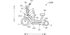
- FIG. 1 is a side view showing the overall configuration of the vehicle 100 according to the first embodiment of the present invention
- FIG. 2 is a plan view. Note that FIG. 1 also shows the usage state of the user PS (dashed-dotted line).
- the vehicle 100 is defined in the front-rear direction (length direction), the left-right direction (width direction), and the up-down direction (height direction) as shown in the figure, and the configuration of each part will be described according to this definition.
- the vehicle 100 has a front wheel 1 and a rear wheel 2, and a frame FL constituting the skeleton of the vehicle 100, and a center line CL1 (FIG. 1) passing through the center of the vehicle 100 in the left-right direction.
- the whole is symmetrical with respect to 2).
- the front wheels 1 are arranged along the center line CL1, and the left and right rear wheels 2 are arranged symmetrically with respect to the center line CL1.
- the front wheel 1 has a larger diameter than the rear wheel 2.
- the front wheel 1 may have the same diameter as the rear wheel 2, or the rear wheel 2 may have a larger diameter than the front wheel 1.
- the frame FL has a front frame 10 and a rear frame 20. As shown in FIG. 1, a part of the frame FL extends along the axis CL2 passing through the center of the vehicle 100 in the left-right direction above the center line CL1, more specifically, tilting forward with an uphill slope (upward). Extends along the axis CL2. As shown in FIG. 2, the axis CL2 overlaps the center line CL1 of the vehicle 100 in a plan view.
- FIG. 3 is a cross-sectional view (cross-sectional view along the line III-III of FIG. 1) along the axis CL2 showing the configuration of the main part on the front side of the vehicle 100.
- the front frame 10 extends in the front-rear direction along the axis CL2, that is, the support frame 11 having a substantially cylindrical cross section extending in an upward gradient toward the front, and the support frame 11. It has a vertical frame 12 having a substantially cylindrical cross section, which is provided integrally with the support frame 11 so as to penetrate the central portion in the front-rear direction.
- the vertical frame 12 is inclined so that the upper end portion is located behind the lower end portion and extends in the vertical direction, and the handle shaft 13 having a substantially circular cross section is rotatably inserted inside the vertical frame 12.
- the central portion of the handle 14 in the left-right direction is fixed to the upper end portion of the handle shaft 13, and the front fork 15 is fixed to the lower end portion.
- the front wheel 1 is rotatably supported via a rotation shaft 1a supported by the front fork 15.
- the front wheel 1 is steered by the rotation operation of the handle 14 about the handle shaft 13.
- the handle 14 extends in the left-right direction, and grips 14a gripped by the user PS are provided at both left and right ends thereof.
- a substantially arcuate front fender 16 is attached to the front fork 15 from above to the rear of the front wheel 1 so as to cover the periphery of the front wheel 1.
- the traveling motor 4 (in-wheel motor) and the brake unit 5 are housed inside the front wheel 1.
- the traveling motor 4 is arranged on the left side and the brake unit 5 is arranged on the right side.
- the vehicle 100 is configured as an electric vehicle that travels by driving a traveling motor 4.
- the brake unit 5 is configured as, for example, a drum brake unit constituting a drum brake.
- a brake unit is also provided on the rear wheel 2. As shown in FIG. 2, these brake units are operated by operating a brake lever 14b provided in front of the grip 14a of the steering wheel 14, and braking force is applied to the front wheels 1 and the rear wheels 2.
- the traveling motor 4 may be provided in the rear wheel 2 instead of the front wheel 1, or in both the front wheel 1 and the rear wheel 2. This makes it possible to improve the traction ability and the climbing ability.
- the battery 6 is a secondary battery such as a lithium ion battery that stores electric power supplied to the traveling motor 4 as an electric motor, and the electric power supplied from the battery 6 to the traveling motor 4 is controlled by a power control unit (not shown). Will be done.
- the steering wheel 14 is provided with a display unit for displaying vehicle information such as the remaining battery capacity and the set vehicle speed, as well as a starter switch for instructing on / off of the main power supply and an accelerator lever for inputting a traveling command. Etc. are provided so as to be operable by the user PS.
- the battery 6 may be arranged inside or around other structural members.
- the rear frame 20 extends in the front-rear direction along the axis CL2, that is, a pair of left and right support frames 21 having a substantially cylindrical cross section extending in an upward gradient toward the front.
- Have. Brackets 22 are joined to the rear ends of the left and right support frames 21.
- the left and right brackets 22 extend rearward and outward in the left-right direction, respectively, and rear wheel support portions 23 are provided at the rear end portions of the brackets 22, and the rear wheels 2 are supported by the rear wheel support portions 23. It is rotatably supported via the rotation shaft 2a.
- side frames 24 are projected from the left and right support frames 21 toward the outside in the left-right direction.
- a rear fender 25 is attached to the rear end portion of the side frame 24 so as to cover the periphery of the rear wheel 2 from the front to the upper side and the rear of the rear wheel 2.
- the side frame 24 is provided with a shaft portion 24a extending in the left-right direction.
- Steps (foot rests) 26, which are substantially rectangular plates in a plan view extending in the front-rear direction, are arranged adjacent to the support frames 21 on the outside in the left-right direction of the left and right support frames 21.
- the rear end portion of step 26 is rotatably supported by the shaft portion 24a.
- the maximum width of the vehicle 100 is defined by, for example, the handle 14 or the step 26.
- Rods 27 are projected downward at the center of the left and right support frames 21 in the front-rear direction.
- a support plate 28 (FIG. 2) is projected from the lower ends of the left and right rods 27 toward the outside in the left-right direction.
- the front end portion of the step 26 is placed on the upper surface of the support plate 28, whereby the downward rotation of the step 26 is restricted.
- the upper surface of the step 26 extends in the horizontal direction in parallel with the road surface 3, and the step 26 is in a horizontal posture.
- the position of step 26 (FIG. 1) in this case is called a horizontal position.
- the step 26 When the step 26 is in the horizontal posture, the user PS can ride with his / her foot on the step 26.
- the step 26 rotates upward with the shaft portion 24a as a fulcrum, the step 26 takes an upwardly inclined posture in which the front end portion moves upward.
- the position of step 26 in this case is called an inclined position.
- the support plate 28 is defined to have a protrusion amount in the left-right direction so as not to interfere with the rear wheel 2 of the other vehicle 100 when another vehicle 100 is parked behind the vehicle 100 (FIG. 5). ..
- the support plate 28 is arranged so that its tip portion is located inside the rear wheel 2 in the left-right direction.
- the support plate 28 may be omitted, and the shaft portion 24a may be provided with a portion or mechanism for restricting the downward rotation of the step 26.
- Step 26 is located below the upper end of the rear wheel 2 in a horizontal posture. As a result, the position of the center of gravity of the user PS who gets on the vehicle 100 is lowered, and the stability at the time of getting on the vehicle is improved.
- the step 26 in the horizontal posture is located above the rotation axis 2a of the rear wheel 2.
- the front end portion of the step 26 is formed so as to be inclined forward. This makes it possible to prevent the foot of the user PS from moving forward beyond step 26. Further, when the front end portion of the step 26 collides with an obstacle on the road surface during traveling, the feet of the occupant can be protected. Since the side frame 24 is provided at the rear end of the step 26 so as to bulge above the upper surface of the step 26, it is possible to prevent the foot of the user PS from moving backward beyond the step 26.
- the front frame 10 and the rear frame 20 are swingably connected via the connecting portion 7.
- the connecting portion 7 the configuration of the connecting portion 7 will be described.
- a pair of front and rear connecting frames 210 having a substantially cylindrical cross section are joined to the front ends of the left and right support frames 21 of the rear frame 20.
- the connecting frame 210 is joined to the supporting frame 21 so that the supporting frame 21 penetrates the connecting frame 210 in the front-rear direction.
- the front and rear connecting frames 210 extend in the left-right direction so as to be orthogonal to the support frame 21.
- Bearings 71 and 72 are provided at the center of the front and rear connecting frames 210 in the left-right direction, respectively, and both front and rear ends of the support frame 11 are rotatably supported by the connecting frame 210 via the bearings 71 and 72. As a result, the front frame 10 (support frame 11) can swing in the left-right direction with respect to the rear frame 20 about the axis CL2.
- the connecting portion 7 is provided with a damper member (spring member) that exerts a restoring force that regulates the swing of the front frame 10 with respect to the rear frame 20.
- the Knighthardt rubber spring 75 is used as the spring member, and the cover 76 of the Knighthardt rubber spring 75 is fixed to the front surface of the connecting frame 210 on the rear side by a bolt.
- FIG. 4 is a cross-sectional view taken along the line IV-IV of FIG. 3 showing the configuration of the Knighthardt rubber spring 75.
- the cover 76 is formed in a substantially box shape as a whole, and flange portions 76a for attaching to the connecting frame 210 are provided at both left and right ends of the cover 76.
- the Nithhardt rubber spring 75 has a substantially rhombic cam block 751 coupled to the outer peripheral surface of the support frame 11 so as to be rotatable integrally with the support frame 11 (for example, coupled via a spline or serration), and a concave shape of the cam block 751. It has a plurality of rubber rollers 752 arranged to face each surface formed on the surface.
- FIG. 4 shows an aspect of the Knighthardt rubber spring 75 when the front frame 10 is in the reference posture.
- the reference posture refers to a neutral state in which the handle shaft 13 is arranged without being tilted in the left-right direction. In this state, the restoring force does not act on the Knighthardt rubber spring 75.
- torque acts on the support frame 11 due to the swing of the front frame 10, and when the support frame 11 rotates about the axis CL2, the rubber roller 752 is pressed between the cover 76 and the cam block 751. Elastically deforms, and the rubber roller 752 becomes elliptical.
- the rotation resistance with respect to the cover 76 increases.
- the rubber roller 752 returns to its original shape due to the elastic force, and the front frame 10 returns to the reference posture.
- the front frame 10 By providing the front frame 10 so as to be swingable via the connecting portion 7 in this way, the user can easily turn the vehicle in the left-right direction.
- the user PS slightly bends the knees and ankles and tilts the upper body to the left and right.
- the front frame 10 can be swung and the front wheel 1 can be tilted to the left or right in a stable posture with both feet resting on the step 26.
- the vehicle 100 can be turned smoothly, and the turning performance is improved.
- the axis CL2 extends forward (FIG. 1). Therefore, when the vehicle 100 is turning, the turning angle of the front wheel 1 with respect to the rear wheel 2 can be increased. As a result, the turning radius can be reduced and the turning performance can be further improved.
- the Knighthardt rubber spring 75 in the connecting portion 7, when the front frame 10 is swung from the reference posture, a restoring force acts on the front frame 10 to satisfactorily suppress the swing of the front frame 10. be able to.
- the number of rubber rollers 752 of the Knighthardt rubber spring 75 may be less than or more than four. Therefore, the cam block 751 may have a shape other than the rhombus.
- a restoring force may be applied to the front frame 10 by an elastic member such as a coil spring instead of the Nithard rubber spring 75. That is, the structure of the damper member is not limited to the Knighthardt rubber spring 75.
- the load point acting on step 26 due to the weight of the user PS at the time of boarding is located in the triangular region connecting the ground contact point of the front wheel 1 and the ground contact points of the pair of left and right rear wheels 2 in a plan view. do.
- the user PS can get on the vehicle 100 in a stable posture regardless of whether the vehicle is running or stopped.
- FIG. 5 is a side view showing an example in which a plurality of (for example, four) vehicles 100 according to the first embodiment are parked
- FIG. 6 is a plan view.
- the vehicles 100 have the same configuration as each other, and for convenience, each vehicle 100 is referred to as a first vehicle 100-1, a second vehicle 100-2, a third vehicle 100-3, and a fourth vehicle 100-4 in order from the front side. There is.
- each vehicle 100 has a pair of left and right support frames 21, and the left and right support frames 21 are arranged so as to be separated by a predetermined distance L1 with the center line CL1 interposed therebetween.
- a gap SP with an open rear surface is formed between the two.
- the distance L1 is longer than the width L2 in the left-right direction of the front wheel 1.
- the front wheel 1 of another vehicle 100 can be inserted into the gap SP of the vehicle 100 from behind. That is, the front wheel 1 of the second vehicle 100-2 is placed in the gap SP of the first vehicle 100-1, the front wheel 1 of the third vehicle 100-3 is placed in the gap SP of the second vehicle 100-2, and the front wheel 1 of the third vehicle 100-3 is placed in the gap SP of the third vehicle 100-3.
- the front wheels 1 of the fourth vehicle 100-4 can be inserted into the gap SP, respectively.
- the front end portion of the step 26 in the horizontal posture comes into contact with the rear surface of the rear wheel 2 of the vehicle 100 in front, that is, the rear surface above the rotation shaft 2a.
- the front end portion of the step 26 rotates around the shaft portion 24a as a fulcrum and is pushed upward along the rear wheel 2, and the step 26 is in an inclined posture. That is, step 26 of the second vehicle 100-2 along the rear wheel 2 of the first vehicle 100-1 and step 26 of the third vehicle 100-3 along the rear wheel 2 of the second vehicle 100-2.
- Step 26 of the fourth vehicle 100-4 is pushed up along the rear wheel 2 of the third vehicle 100-3.
- Step 26 is located above the rotation axis 2a of the rear wheel 2 in the horizontal posture (FIG. 1). Therefore, when the front end portion of the step 26 comes into contact with the rear wheel 2 of the vehicle 100 in front, the step 26 can be smoothly rotated upward. If the front end of step 26 is provided so as to be inclined forward so that the front end of step 26 comes into contact with the rear wheel 2 above the rotation shaft 2a of the rear wheel 2, step 26 (front end).
- the horizontal portion other than the portion may be located at the same height as the rotating shaft 2a or below the rotating shaft 2a. However, in order to prevent the bottom surface of the step 26 from interfering with the unevenness of the road surface 3, it is preferable that the step 26 is located above the rotation shaft 2a.
- the gap of the vehicle 100 in front is provided.
- a plurality of vehicles 100 can be parked by inserting the front wheel 1 into the SP. Therefore, the overall length of the plurality of vehicles 100 in the parked state in the front-rear direction can be shortened, and the plurality of vehicles 100 can be efficiently parked in the limited parking space.
- the step 26 is rotatably provided around the shaft portion 24a, the step 26 can be retracted above the rear wheel 2 of the vehicle 100 in front when parking. As a result, the step 26 can be arranged below the upper surface of the rear wheel 2 in the horizontal posture, the position of the center of gravity of the user PS at the time of riding is lowered, and the running stability is improved.
- pins 18 are projected from the left and right outer side surfaces of the front fork 15 of the front frame 10 toward the left and right outer sides, respectively.
- the lower side of the pin 18 is formed in a substantially arc shape (for example, a semicircular shape).
- the length L3 from the tip end portion (right end portion) of the right pin 18 to the tip end portion (left end portion) of the left pin 18 is from the distance L1 between the inner side surfaces of the left and right support frames 21. Is also long.
- guides 29 are provided on the upper surfaces of the left and right support frames 21, respectively.
- FIG. 7 is an enlarged view of a main part (enlarged view of part VII) of FIG. 5 which schematically shows the configuration of the guide 29.
- the guide 29 is formed on the upper surface of the support frame 21 by bulging upward.
- a substantially arc-shaped recess 29a corresponding to the pin 18 is provided on the upper surface of the guide 29.
- an inclined surface 29b is formed so as to incline downward toward the rear.
- the top portion 29c of the front end of the inclined surface 29b is located above the bottom surface of the recess 29a.
- the front wheel 1 of the second vehicle 100-2 When the front wheel 1 of the second vehicle 100-2 is inserted into the gap SP of the first vehicle 100-1 from the rear, it protrudes from the front fork 15 of the second vehicle 100-2 as shown by the dotted line in FIG.
- the bottom surface of the pin 18 is brought into contact with the upper surface of the support frame 21 of the first vehicle 100-1.
- the pin 18 moves forward along the upper surface of the support frame 21 and the inclined surface 29b of the guide 29. Then, the pin 18 is engaged with the recess 29a beyond the top portion 29c of the inclined surface 29b.
- the front fork 15 (pin 18) of the second vehicle 100-2 is held by the support frame 21 (guide 29) of the first vehicle 100-1.
- the front wheel 1 of the second vehicle 100-2 floats up from the road surface 3 and becomes a non-grounded state, and is arranged with a gap from the front fender 16 of the first vehicle 100-1.
- the engagement of the pin 18 and the guide 29 defines the position of the second vehicle 100-2 with respect to the first vehicle 100-1, but the front wheel 1 is lifted and is not clearly shown in FIG.
- the positional relationship between the pin 18 and the guide 29 is defined so that the front wheel 1 does not come into contact with the front fender 16 of the vehicle 100 in front.
- the relationship between the first vehicle 100-1 and the second vehicle 100-2 is the relationship between the second vehicle 100-2 and the third vehicle 100-3, and the relationship between the third vehicle 100-3 and the fourth vehicle 100-.
- each vehicle 100 can be sequentially connected by engaging the pin 18 and the guide 29.
- the rear wheels 2 of the connected vehicle 100 are grounded, but the front wheels 1, which are the driving wheels, are not grounded.
- the pin 18 is engaged with the guide 29, it is necessary to move the pin 18 upward along the upper surface of the support frame 21 inclined forward to reach the guide 29, and this engaging operation is a vehicle. It can be easily realized by the inertial force when 100 is advanced along the gap SP.
- the vehicle 100 includes a front wheel 1 and a pair of left and right rear wheels 2 arranged diagonally to the left and diagonally to the rear of the front wheel 1, and extends in the front-rear direction, and a pair of left and right wheels.
- a pair of left and right support frames 21 having rear wheel support portions 23 that rotatably support the rear wheels 2 are provided (FIGS. 1 and 2).
- the pair of left and right support frames 21 are separated from each other by a predetermined distance L1 so that the front wheels 1 of another vehicle 100 having the same shape as the vehicle 100 can be inserted from the rear into the gap SP between the pair of left and right support frames 21.
- Fig. 6 are spaced apart.
- the vehicle 100 further includes a front fork 15 that rotatably supports the front wheel 1 (FIG. 1).
- the front fork 15 has a pair of left and right pins 18 projecting outward in the left-right direction, and the pair of left and right pins 18 has a distance L3 from the tip of the left pin 18 to the tip of the right pin 18. It is provided so as to be longer than a predetermined distance L1 (FIG. 6).
- the pair of left and right support frames 21 each have a guide 29 to which the pair of left and right pins 18 of the rear vehicle 100 inserted into the gap SP can be engaged from above (FIG. 7). Therefore, by engaging the pin 18 and the guide 29, the vehicles 100 can be easily connected to each other while restricting the position between the pair of front and rear vehicles 100.
- the pair of left and right pins 18 and the pair of left and right guides 29 are such that when the pair of left and right pins 18 of the rear vehicle 100 are engaged with the pair of left and right guides 29, the front wheels 1 of the rear vehicle 100 are paired left and right. It is provided so as to be located above the rear wheel 2. As a result, the front wheel 1 of the vehicle 100 behind is held in a non-grounded state, so that the plurality of vehicles 100 can be easily towed.
- the guide 29 is provided on the upper surface of the pair of left and right support frames 21 (FIG. 1).
- the pair of left and right support frames 21 are provided so that their upper surfaces are inclined downward with a downward gradient (FIG. 1).
- the front wheel 1 of the vehicle 100 can be easily floated when the vehicle 100 is advanced along the gap SP of the vehicle 100 in front.
- the vehicle 100 further includes a pair of left and right steps 26 on which the left and right feet of the user PS are placed (FIG. 1).
- the pair of left and right steps 26 are supported by the pair of left and right support frames 21 (FIG. 1).
- the vehicle 100 can be configured as a standing vehicle on which the user PS rides in a standing posture. This type of standing vehicle is small, easy to handle, and is an easily available means of transportation for the user PS.
- the pair of left and right steps 26 is from the horizontal position when the vehicle 100 is used via the pair of left and right shaft portions 24a extending in the left-right direction arranged below the upper ends of the pair of left and right rear wheels 2. Each is rotatably supported over the tilted position when not in use (Fig. 5). As a result, even when the step 26 is provided at a low position such that it comes into contact with the rear wheel 2, the step 26 can be retracted above the rear wheel 2 when parking.
- the pair of left and right steps 26 are provided so that the front ends of the pair of left and right steps 26 are positioned above the rotation shafts 2a of the pair of left and right rear wheels 2 in a horizontal posture (FIG. 1).
- the step 26 can be smoothly rotated upward along the rear surface of the rear wheel 2 of the vehicle 100 in front.
- the vehicle 100 extends in the front-rear direction with a handle 14 arranged above the front wheel 1 and a front frame 10 (support frame 11) that supports the front wheel 1 so as to be steerable by operating the handle 14.
- a connecting portion 7 that swingably supports the support frame 11 in the left-right direction with respect to the rear frame 20 (support frame 21) around the axis CL2 is provided (FIGS. 1 and 3).
- the front frame 10 that supports a single front wheel 1 is swingably supported via the connecting portion 7 with respect to the rear frame 20 that supports the pair of left and right rear wheels 2, so that the front wheels 1 can swing during turning. It can be tilted to improve the turning performance of the vehicle 100.
- Embodiment- A second embodiment of the present invention will be described with reference to FIGS. 8A to 15B. In the following, the differences from the first embodiment will be mainly described.
- the second embodiment is different from the first embodiment in that a lock mechanism for locking the swing of the front frame 10 with respect to the rear frame 20 is provided.
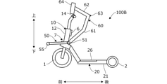
- FIGS. 8A and 8B are side views showing the overall configuration of the vehicle 100A according to the second embodiment, respectively.
- FIG. 8A is a diagram showing an unlocked state in which the lock mechanism is unlocked
- FIG. 8B is a diagram showing a locked state in which the lock mechanism is locked.
- the same parts as those in FIGS. 1 and 2 are designated by the same reference numerals.
- a lever member 50 formed by joining a plurality of rod-shaped members into a frame shape is attached to the front frame 10 of the vehicle 100A, more specifically, the holder 17 of the battery 6. ..
- FIGS. 8A, 8B, 9A, and 9B are cross-sectional views (viewing the lever member 50 from below) along the lines AA of FIG. 8A and the line BB of FIG. 8B showing the configuration of the lever member 50, respectively.
- a bracket 171 is projected from the bottom of the holder 17 toward the rear from the central portion in the left-right direction.
- a terminal portion 172 is projected upward from the tip end portion (rear end portion) of the bracket 171.
- the upper end portion of the terminal portion 172 is formed in a convex shape, and the positive and negative electrodes T1 are provided on the convex portion.
- the lever member 50 has a substantially circular shaft portion 51 extending in the left-right direction beyond the left and right end faces of the holder 17.
- the left-right central portion of the shaft portion 51 is rotatably supported on the upper surface of the bracket 171.
- a pair of front and rear arms (front arm 52, rear arm 53) having a substantially cylindrical cross section are joined to the left and right ends of the shaft portion 51.
- the front arm 52 has a pair of left and right side arms 521 and a connecting arm 522 extending in the left-right direction and connecting the front ends of the side arms 521 to each other in a plan view. It has a substantially U-shape.
- the side arm 521 is bent upward at a substantially right angle in the middle, and exhibits a substantially L-shaped side view.
- a pad 54 having a substantially rectangular parallelepiped shape is attached to the bent portion of the side arm 521.
- the bottom surface of the pad 54 is formed in a substantially arc shape in the front-rear direction.
- a sliding member 21a is mounted on the upper surfaces of the left and right support frames 21 below the pad 54 over a predetermined length in the front-rear direction.
- the sliding material 21a is provided to facilitate the sliding of the pad 54 on the support frame 21, and is composed of an elastic body such as hard rubber.
- the pad 54 may be made of an elastic body.
- the side arm 521 extends forward beyond the vertical frame 12 extending above the front wheel 1, and the connecting arm 522 is located in front of the vertical frame 12.
- a terminal portion 55 is provided so as to project upward, downward, or downward from the central portion of the connecting arm 522 in the left-right direction.
- the bottom portion of the terminal portion 55 is formed in a concave shape so as to be fitted to the upper end portion of the terminal portion 172 of the other vehicle 100A in front, and the positive and negative electrodes T2 are provided in the concave portion.
- the electrode T1 (terminal portion 172) and the electrode T2 (terminal portion 55) are connected to the battery 6 of the vehicle 100A via a power line (FIG. 14).
- the rear arm 53 has a pair of left and right side arms 531 and a connecting arm 532 that connects the rear ends of the side arms 531 to each other, and has a substantially U-shape in a plan view.
- the side arm 531 extends rearward beyond the terminal portion 172, and the connecting arm 532 is located rearward of the terminal portion 172.
- the connecting arm 532 is operated in the vertical direction by the user PS, whereby the lever member 50 rotates around the shaft portion 51 as a fulcrum.
- the position of the lever member 50 in FIG. 8A is referred to as an unlock position
- the position of the lever member 50 in FIG. 8B is referred to as a lock position.
- FIG. 10A is a diagram showing the positional relationship between the pad 54 and the sliding member 21a at the unlocked position (arrow view Z1 in FIG. 8A).
- a part of the lever member 50 is not shown.
- a gap SPA is formed between the bottom surface of the pad 54 and the sliding member 21a.
- the rear frame 20 can swing in the direction of the arrow R about the axis CL2, and the vehicle 100A can travel while tilting the front wheel 1 in the left-right direction.
- FIG. 10C is a diagram showing the positional relationship between the pad 54 and the sliding member 21a at the locked position (arrow view Z2 in FIG. 8B). As shown in FIG. 10C, when the lever member 50 is located at the locked position, the bottom surface of the pad 54 comes into contact with the upper surface of the sliding member 21a. Therefore, the rear frame 20 cannot swing around the axis CL2.
- the lever member 50 is operated to the locked position when the vehicle 100A is parked. As a result, the vehicle 100A can be parked in a stable posture in which rocking is blocked (locked).
- an outer cable in which the brake wire connected to the brake unit is housed is arranged in the vicinity of the lever member 50, and when the lever member 50 is operated from the unlocked position to the locked position, The outer cable is pressed by the lever member 50. As a result, a tensile force acts on the brake wire, and the brake units of the front wheels 1 and the rear wheels 2 can be operated. That is, the parking brake can be operated at the same time by operating the lever member 50 to the locked position.
- the lever member 50 functions not only as a locking mechanism for the vehicle 100A but also as a connecting mechanism for connecting a plurality of vehicles 100A.
- FIG. 11 is a side view showing a state in which a plurality of vehicles 100A are connected via the lever member 50
- FIG. 12 is a plan view. 11 and 12 show an example in which two vehicles 100A (first vehicle 100A-1 and second vehicle 100A-2) are connected for convenience. 11 and 12, as in FIGS. 5 and 6, the rear vehicle 100A, that is, the pin 18 of the second vehicle 100A-2 is engaged with the front vehicle 100A, that is, the guide 29 of the first vehicle 100A-1. Combined, the front wheel 1 of the second vehicle 100A-2 is in a non-grounded state.
- the lever member 50 of the second vehicle 100A-2 is in the locked position with the pin 18 of the second vehicle 100A-2 engaged with the guide 29 of the first vehicle 100A-1.
- the terminal portion 55 of the lever member 50 of the second vehicle 100A-2 is fitted to the terminal portion 172 of the holder 17 of the first vehicle 100A-1.
- the plurality of vehicles 100A can be more firmly connected via the lever member 50. Therefore, a plurality of vehicles 100A can be easily moved from the parking lot (station) to another station at once.
- the terminal portion 55 of the second vehicle 100A-2 When the terminal portion 55 of the second vehicle 100A-2 is fitted to the terminal portion 172 of the first vehicle 100A-1, the electrode T2 of the second vehicle 100A-2 and the electrode T1 of the first vehicle 100A-1 are connected. Will be done. As a result, electric power can be supplied to the battery 6 of each vehicle 100A from the electric power supply unit installed in the station.
- the terminal portions 55 and 172 of the vehicle 101A described above are used for terminal portions other than the power supply, for example, for communicating with each other the state of the vehicle such as the vehicle ID for identifying the vehicle 100A and the information on the remaining battery level.
- the terminal part to be used is also included.
- the configuration of the lock mechanism that connects the front and rear vehicles 101A is not limited to that described above.
- the vehicle 101A may be mechanically coupled to the vehicle 101A in front or behind, and the locking management thereof may be electrically performed. Locking management may be performed with a physical key.
- FIG. 13 shows a plurality of vehicles 100A (first vehicle 100A-1, second vehicle 100A-2, third vehicle 100A-3, fourth) from the power supply unit installed in the station ST, that is, the battery BT for power supply. It is a figure which shows the example of the case where electric power is supplied to each battery 6 of a vehicle 100A-4). More specifically, from the state where the first vehicle 100A-1 to the third vehicle 100A-3 are parked at the station ST, the fourth vehicle 100A-4 is newly parked at the station ST as shown by the arrow. It is a figure which shows an example. In FIG. 13, the lever member 50 is not shown.
- the station ST is a parking lot for the vehicle 100A, and is a rental place and a return place for the vehicle 100A when the vehicle 100A is used as a sharing vehicle. Since the vehicle 100A is an electric vehicle that travels by electric power from the battery 6, when the remaining capacity of the battery 6 becomes a predetermined value or less, the vehicle 100A cannot travel. Therefore, in the station ST, the battery 6 is charged at the same time while the lever member 50 of each vehicle 100A is operated to the locked position.
- the station ST may be fixed or mobile.
- the power supply unit may be an AC power supply, and in that case, power may be supplied to the battery 6 after converting AC to DC via an AC adapter.
- the moving means of the station ST may be manual or automatic.
- the installation position of the station ST can be changed according to the day of the week, time, and the like. For example, a station ST can be installed near the station during commuting hours and in the middle of the office district during the day. That is, the station ST can be installed in a place where the demand for using the vehicle 100A is high, and thereby the frequency of use of the vehicle 100A can be increased.
- FIG. 13 is an example of a manual mobile station ST.
- a hand-push type power supply cart 200 is arranged in advance in the station ST.
- the power cart 200 has, for example, a pair of left and right tires 201 and a support pole 202, and three points can be grounded to the road surface 3 and can stand on their own.
- the power supply cart 200 can be easily moved while rolling the tire 201.
- the power supply cart 200 is equipped with battery BTs at two locations on the left and right, for example.
- the power supply cart 200 has a connecting portion to which the first vehicle 100A-1 is connected. More specifically, a guide (referred to as a station guide) with which a pin 18 (FIG. 11) projecting from the front fork 15 of the first vehicle 100A-1 is engaged and a terminal portion 55 of the first vehicle 100A-1. It has a terminal portion (referred to as a station terminal portion) to which (FIG. 11) is fitted.
- the positional relationship between the station guide and the station terminal portion is the same as the positional relationship between the guide 29 and the terminal portion 172 of each vehicle 100A.
- the station terminal portion has an electrode electrically connected to the battery BT.
- the terminal portion 55 of the first vehicle 100A-1 becomes the station terminal.
- the first vehicle 100A-1 can be held in a state where the front wheel 1 is floated by being fitted to the portion.
- the battery 6 of the first vehicle 100A-1 is connected to the battery BT via the terminal portion 55, and the electric power of the battery BT can be supplied to the battery 6 to charge the battery 6.
- FIG. 14 is an electric circuit diagram schematically showing the configuration of a power supply circuit in a connected state of a plurality of vehicles 100A-1 to 100A-4.
- the terminal portion 55 (electrode T2) of each vehicle 100A-1 to 100A-4 is connected to the terminal portion 172 (electrode T1) via a power line, and controls constituting the power control unit. It is connected to the battery 6 in parallel with the terminal portion 172 via the circuit 6a.
- the terminal portion 55 of the first vehicle 100A-1 is attached to the station terminal portion BTa
- the terminal portion 55 of the second vehicle 100A-2 is attached to the terminal portion 172 of the first vehicle 100A-1
- the third vehicle 100A-3 is connected to the terminal portion 55
- the terminal portion 55 of the fourth vehicle 100A-4 is connected to the terminal portion 172 of the third vehicle 100A-3.
- the control circuit 6a of each vehicle 100A-1 to 100A-4 includes, for example, a power switch for connecting (on) or disconnecting (off) the terminal portion 55 (electrode T2) and the battery 6, and the power switch is the control circuit 6a. It is turned on and off by the controller of.
- each vehicle 100A determines whether or not the terminal portion 55 of another vehicle 100A is connected to the terminal portion 172, and if it is determined that the terminal portion 55 is connected, the power switch is turned on. Turn off. On the other hand, if it is determined that the terminal portion 55 is not connected, the power switch is turned on.
- the controller in FIG. 14, the power switches of the first vehicle 100A-1, the second vehicle 100A-2, and the third vehicle 100A-3 are turned off. Therefore, charging of the battery 6 of the first vehicle 100A-1, the second vehicle 100A-2, and the third vehicle 100A-3 from the battery BT is prevented.
- the power switch of the 4th vehicle 100A-4 is turned on.
- the battery 6 of the fourth vehicle 100A-4 is charged. That is, among the plurality of vehicles 100A-1 to 100A-4 in the connected state, the battery 6 of the vehicle 100A-4 located at the rearmost position is preferentially charged.
- the vehicle 100A-4 located at the end is used first by the user PS. Therefore, it is possible to prevent the battery 6 from becoming insufficiently charged at the start of use of the vehicle 100A.
- An SOC sensor for detecting the charge rate SOC of the battery 6 of each vehicle 100A is provided, and when the charge rate detected by the SOC sensor exceeds a predetermined value, the power switch of the previous vehicle 100A is turned on. good. That is, when the charge rate of the fourth vehicle 100A-4 exceeds the predetermined value, the power switch of the third vehicle 100A-3 is turned on, and when the charge rate of the third vehicle 100A-3 exceeds the predetermined value, the second vehicle 100A-
- the power switch of No. 2 may be turned on, and the power switch of the first vehicle 100A-1 may be turned on when the charge rate of the second vehicle 100A-2 becomes a predetermined value or more.
- the batteries 6 of each vehicle 100A-1 to 100A-4 can be sequentially charged while prioritizing them.
- a variable resistor is provided and the resistance value of the variable resistor is controlled to control the power supplied to the battery 6 of each vehicle 100A. May be controlled.
- the user PS operates the lever member 50 to the lock position to lock the swing of the vehicle 100, connect the vehicles 100 to each other, and connect the terminal portion 55 for charging the battery 6. And can be done at the same time. That is, three operations or functions can be simultaneously realized by a single rotation operation of the lever member 50 by the user PS when parking the vehicle 100.
- the terminal portion 55 is attached / detached to / from the terminal portion 172 of another vehicle 100A or the station terminal portion BTa, and if it is determined that the terminal portion 55 is attached / detached, it is determined that the vehicle 100A has started to be used and has been returned. good. Thereby, the usage time of the vehicle 100A can be easily calculated. Therefore, the vehicle 100A can be easily managed, and the user PS can be appropriately charged according to the usage time of the vehicle 100A.
- FIG. 15A is a diagram showing a modification of FIG. 13.
- the power cart 200 is connected to a two-wheeled vehicle 215 such as a bicycle.
- the power cart 200 can be easily transported together with the plurality of vehicles 100A in the connected state, and the station ST for the vehicle 100A can be quickly installed in a new place.
- the battery BT is mounted on the two-wheeled vehicle 215, and the two-wheeled vehicle 215 is provided with a connecting portion (station guide, station terminal portion) to which the first vehicle 100A-1 is connected. good.
- FIG. 15B is a diagram showing another modification of FIG. 13.
- a plurality of vehicles 100A are connected to a robot 220 having a battery BT for power supply.
- the robot 220 is a self-propelled robot having wheels that rotate by being driven by a traveling motor.
- the robot 220 automatically travels along a predetermined target route at a predetermined timing according to a predetermined program. As a result, it is possible to save the trouble of transporting the vehicle 100A by the worker.
- the vehicle 100A has a space between an unlock position that allows the front frame 10 (support frame 11) to swing with respect to the rear frame 20 (support frame 21) and a lock position that prohibits the swing by the operation of the user PS.
- a lever member 50 rotatably attached to the front frame 10 (holder 17) so as to be movable is further provided (FIGS. 8A and 8B). As a result, the swing of the vehicle 100A can be locked when the vehicle is parked, and the vehicle 100A can be in a stable parking state.
- the vehicle 100A includes a traveling motor 4 for driving the front wheels 1 and a battery 6 for supplying electric power to the traveling motor 4 (FIG. 8A).
- the lever member 50 has a terminal portion 55 (electrode T2) electrically connected to the battery 6 (FIG. 8A).
- the battery 6 can be connected to the battery BT for power supply installed in the station ST via the terminal portion 55 (FIG. 14), and the battery 6 can be easily charged. It can be carried out.
- the terminal portion 55 is a terminal portion 172 (electrode T1) of another vehicle 100A arranged in front of the vehicle 100A, that is, another vehicle 100A having the same configuration as the vehicle 100A when the lever member 50 is located at the locked position. ) Is provided so as to be electrically connected (FIG. 11). As a result, the terminal portion 55 can be easily connected to the battery BT for power supply via the terminal portions 55 and 172 of the other vehicle 100A.
- the terminal portion 55 of the first vehicle 100A-1 parked at the frontmost portion is connected to the battery BT provided in the power supply cart 200 or the like arranged in the station ST when the lever member 50 is located at the locked position. It is provided so as to be (Fig. 13). As a result, the first vehicle 100A-1 and the battery BT for power supply can be easily connected by operating the lever member 50.
- the third embodiment differs from the second embodiment mainly in the configuration of the lever member 50. That is, in the third embodiment, a seat on which the user PS can be seated is provided integrally with the lever member 50.
- FIGS. 17A and 17B are plan views. 16A and 17A show a state in which the lever member 50 is operated to the unlocked position, and FIGS. 16B and 17B show a state in which the lever member 50 is operated to the locked position.
- the configuration of the pair of left and right support frames 21 is also different from that of the second embodiment.
- the support frame 21 has a horizontal portion 211 extending substantially horizontally in the front-rear direction and a first diagonally extending diagonally upward from the front end of the horizontal portion 211 at a first inclination angle with respect to the horizontal line. It has one inclined portion 212 and a second inclined portion 213 extending diagonally upward from the front end of the first inclined portion 212 at a second inclined angle smaller than the first inclined angle.
- the connecting portion 7 for swingably connecting the front frame 10 and the rear frame 20 is provided on the second inclined portion 213.
- the left and right steps 26 are supported by the horizontal portions 211 of the left and right support frames 21, respectively.
- the pair of left and right support frames 21 are configured such that the first inclined portion 212 and the horizontal portion 211 extend diagonally toward the outside in the left-right direction toward the rear.
- the support frame 21 has a substantially C-shape in a plan view as a whole, and the distance between the left and right support frames 21 is increased toward the rear.
- the support frame 21 is configured to have a substantially C-shape in a plan view, so that the pair of left and right steps 26 are arranged inside the pair of left and right support frames 21, respectively. Therefore, when connecting the other vehicle 100B to the rear of the vehicle 100B, the front wheel 1 of the other vehicle 100B may be inserted from the rear between the left and right steps 26 which is larger than the distance L1 in FIG. 6, and the vehicle 100B may be inserted. Is easy to connect.
- the seat frame 60 is joined to the central portion in the left-right direction of the shaft portion 51 of the lever member 50.
- the seat frame 60 has a front end portion joined to the shaft portion 51 and extends rearward along the center line CL1 in a state where the lever member 50 is located at the unlocked position.
- the 1-seat frame 61 extends in the left-right direction at the connection portion between the 1st seat frame 61, the 2nd seat frame 62 erected diagonally rearward from the rear end portion of the 1st seat frame 61, and the 1st seat frame 61 and the 2nd seat frame 62. It has a third seat frame 63 that is present.
- Each of the seat frames 61 to 63 has, for example, a substantially cylindrical cross section.
- the third seat frame 63 extends to the left and right support frames 21, and when the lever member 50 is located at the unlocked position, the left and right ends of the third seat frame 63 are on the upper surface of the horizontal portion 211 of the support frame 21. It will be placed. Therefore, the downward rotation of the lever member 50 is prevented, and the lever member 50 is supported at the unlocked position.
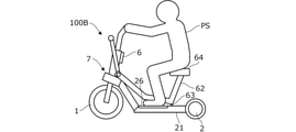
- a seat cushion 64 on which the user PS can be seated is provided at the upper end of the second seat frame 62.
- FIG. 18A and 18B are diagrams showing an example of the riding posture of the user PS in a state where the lever member 50 is operated to the unlocked position.
- FIG. 18A shows a standing posture
- FIG. 18B shows a sitting posture.
- the user PS in the standing posture, the user PS stands with his / her feet on the upper surfaces of the left and right steps 26.
- the first seat frame 61 is arranged in the inseam of the user PS, and the second seat frame 62 and the seat cushion 64 are located behind the user PS. Therefore, even when the seat is integrally provided on the lever member 50, the driving operation of the user PS in the standing posture is not hindered, and the user PS tilts the body to the left and right with the ankle as a fulcrum.
- the vehicle 100B can be driven while swinging the front frame 10 via the connecting portion 7.
- the user PS sits on the seat cushion 64 with both feet placed on the step 26.
- the weight of the user PS acts on the left and right support frames 21 via the seat cushion 64.
- the left and right ends of the third seat frame 63 which is a part of the front frame 10 are pressed against the rear frame 20 (support frame 21), so that the front frame 10 swings in the left-right direction with respect to the rear frame 20. It is suppressed and the user PS can get on the vehicle 100B in a stable posture.
- Spring portions may be provided at both left and right ends of the third seat frame 63 so that the seat frame 60 can be swingably supported via the spring portions.
- the support rigidity of the spring portion may be increased by the action of the user PS's own weight.
- a switch that turns on when the user sits on the seat cushion may be provided to limit the maximum vehicle speed of the vehicle 100B when the switch is turned on, as compared with when the switch is turned off.
- the maximum vehicle speed when the switch is turned on may be limited to a predetermined vehicle speed (for example, 6 km / h).
- the vehicle 100B can be used as a vehicle capable of traveling on the sidewalk (so-called senior car).
- FIG. 19 is a side view showing a state in which a plurality of vehicles 100B (first vehicle 100B-1, second vehicle 100B-2) according to the third embodiment are connected via a lever member 50.
- a lever member 50 when the lever member 50 is rotated to the locked position, the terminal portions 55 and 172 are connected to each other and the battery 6 is charged. It is possible.
- the following effects can be further exerted.
- the vehicle 100B rotates integrally with the lever member 50 so that the user PS cannot be seated when the lever member 50 is in the locked position, while the user PS can be seated when the lever member 50 is in the unlocked position.
- Further provided are possible seats (seat frame 60, seat cushion 64) (FIGS. 16A, 16B).
- the user PS can get on the vehicle 100B in a sitting posture while suppressing the parking space when the vehicle 100B is parked.
- the vehicles 100, 100A, and 100B are configured to have a single front wheel 1 and a pair of left and right rear wheels 2, but are arranged diagonally to the left and diagonally to the rear of one front wheel and front wheels, respectively. If it has only two rear wheels, the wheel configuration is not limited to that described above.
- one front wheel includes not only a single front wheel but also a pair of front wheels provided at one place, that is, a pair of front wheels.
- the support frame 21 as a pair of left and right support members having the rear wheel support portion 23 (support portion) is extended in the front-rear direction, but in the gap between the pair of left and right support members, the other As long as the front wheels of the vehicle are arranged apart from each other by a predetermined distance so that they can be inserted from the rear, the structure of the support member may be any.
- the pair of left and right pins 18 are projected from the front fork 15 as the front wheel support portion that rotatably supports the front wheels.
- the configuration of the protruding portion shape, mounting position, etc.
- the configuration of the guide 29 with which the pin 18 is engaged, that is, the configuration of the engaging portion is not limited to that described above.
- the pair of left and right support frames 21 support the step 26 so as to be rotatable between the horizontal position when riding and the inclined position when not riding, but the occupant's feet are supported.
- the configuration of the mounting portion to be mounted is not limited to that described above.
- the mounting portion may be omitted.
- the front frame 10 (second member) and the support frame 21 (first member) that rotatably support the front wheel 1 with the operation of the handle 14 (steering unit) are connected to each other via the connecting portion 7.
- the CL2 is rotatably connected to the center
- the configuration of the connecting portion that rotatably supports the second member in the left-right direction with respect to the first member is not limited to that described above.
- the swing mechanism may be omitted from the vehicle.
- the lever member is movable so as to be movable between the unlock position (first position) that allows the front frame 10 to swing with respect to the support frame 21 and the lock position (second position) that prohibits the swing.
- the configuration of the operation unit that can be moved between the first position and the second position by the operation of the occupant is not limited to the above. Instead of prohibiting the swing when the operation unit is operated to the second position, the swing may be suppressed more when the operation unit is operated to the second position than when the operation unit is operated to the first position. ..
- the traveling motor 4 (motor) and the battery 6 (storage unit) are mounted on the vehicles 100, 100A, 100B, and the vehicles 100, 100A, 100B are configured as electric vehicles, but the vehicle is other than the electric vehicle. There may be.
- the front wheel 1 of another vehicle (first other vehicle) is inserted from behind the vehicles 100, 100A, 100B, and the terminals of the other vehicle (second other vehicle) in front of the vehicles 100, 100A, 100B are inserted.
- the terminal portion 55 is provided on the lever member 50 so as to be connectable to the portion 172, the terminal portion may be provided at another position.
- the power cart 200 and the like are arranged in the station ST so as to support the leading vehicles 100, 100A, 100B, but the configuration of the vehicle support having the power supply unit connected to the terminal portion of the vehicle is described above. It is not limited to what you have done.
- the seat (seat frame 60, seat cushion 64) is provided integrally with the lever member 50, but when the operation unit is in the second position, the occupant cannot be seated, while the first position.
- Any configuration of the seating portion may be used as long as it is provided so as to be movable integrally with the operating portion so that the seating portion can be seated when the seating portion is located.
- the seat frame 60 when the lever member 50 is located at the unlocked position, the seat frame 60 is supported by the support frame 21, but the configuration of the support portion of the seating portion is not limited to this.
- the swing of the front frame 10 with respect to the rear frame 20 is locked or unlocked by the rotation of the lever member 50, but in this configuration, the front wheel 1 is inserted between the pair of left and right support frames 21. It can be similarly applied even if it does not have a possible void SP. That is, if the vehicle is configured so that the front frame can swing with respect to the rear frame, the vehicle swings in the same manner as described above via the operation unit that can move between the first position and the second position. It can be configured to lock or unlock.
Landscapes
- Engineering & Computer Science (AREA)
- Mechanical Engineering (AREA)
- Power Engineering (AREA)
- Transportation (AREA)
- Automatic Cycles, And Cycles In General (AREA)
- Handcart (AREA)
Abstract
A vehicle (100) comprises a front wheel (1), a pair of left and right rear wheels (2) respectively disposed diagonally left rearward and diagonally right rearward of the front wheel (1), and a pair of left and right support members (21) which extend in the longitudinal direction, respectively, and which also include support parts (23) that allow the pair of left and right rear wheels (2) to rotate, respectively. The pair of left and right support members (21) are disposed so as to be separated from each other by a predetermined distance such that the front wheel (1) of another vehicle (100) configured in the same shape as the vehicle (100) is insertable from the rear into the gap between the pair of left and right support members (21).
Description
本発明は、前輪と後輪とを有する車両に関する。
The present invention relates to a vehicle having front wheels and rear wheels.
従来より、単一の前輪と左右一対の後輪とを有する電動式の3輪車両が知られている(例えば特許文献1参照)。特許文献1記載の車両では、左右の後輪の内側に、立位姿勢の乗員の足が載置される左右一対のステップが設けられるとともに、前輪の上方に、前輪を転舵するためのハンドルが設けられ、電動モータにより後輪が駆動されて車両が走行する。
Conventionally, an electric three-wheeled vehicle having a single front wheel and a pair of left and right rear wheels has been known (see, for example, Patent Document 1). In the vehicle described in Patent Document 1, a pair of left and right steps on which the feet of a standing occupant are placed are provided inside the left and right rear wheels, and a steering wheel for steering the front wheels is provided above the front wheels. Is provided, and the rear wheels are driven by an electric motor to drive the vehicle.
上記特許文献1記載のように構成された車両を単独で駐車する場合、それほど多くの駐車スペースは必要とならない。しかしながら、複数の車両を駐車する場合には、多くの駐車スペースが必要となる。このため、限られたスペースに車両を効率的に駐車可能とすることが要求される。
When parking a vehicle configured as described in Patent Document 1 alone, not so much parking space is required. However, when parking a plurality of vehicles, a large amount of parking space is required. Therefore, it is required that the vehicle can be efficiently parked in the limited space.
本発明の一態様は、前輪と、前輪の左斜め後方および右斜め後方にそれぞれ配置された左右一対の後輪と、を備える車両であって、前後方向にそれぞれ延在するとともに、左右一対の後輪をそれぞれ回転可能に支持する支持部を有する左右一対の支持部材をさらに備える。左右一対の支持部材は、左右一対の支持部材の間の空隙に、車両と同一形状に構成された他の車両の前輪が後方から挿入可能なように互いに所定距離隔てて離間して配置される。
One aspect of the present invention is a vehicle including a front wheel and a pair of left and right rear wheels arranged diagonally to the left and diagonally to the rear of the front wheel, which extend in the front-rear direction and have a pair of left and right wheels. Further, a pair of left and right support members having support portions for rotatably supporting the rear wheels are further provided. The pair of left and right support members are arranged in a gap between the pair of left and right support members at a predetermined distance from each other so that the front wheels of another vehicle having the same shape as the vehicle can be inserted from the rear. ..
本発明によれば、複数の車両を限られたスペースに効率的に駐車することができる。
According to the present invention, a plurality of vehicles can be efficiently parked in a limited space.
-第1実施形態-
以下、図1~図7を参照して本発明の第1実施形態について説明する。本発明の第1実施形態に係る車両は、単一の前輪と左右一対の後輪とを有する三輪車両であり、ユーザが立位姿勢で乗車可能に構成される。この車両は、例えば多数のユーザが利用可能なシェアリング車両として用いられ、複数の車両が所定場所(ステーション)に集めて駐車される。 -First Embodiment-
Hereinafter, the first embodiment of the present invention will be described with reference to FIGS. 1 to 7. The vehicle according to the first embodiment of the present invention is a three-wheeled vehicle having a single front wheel and a pair of left and right rear wheels, and is configured so that the user can ride in a standing posture. This vehicle is used, for example, as a sharing vehicle that can be used by a large number of users, and a plurality of vehicles are collected and parked at a predetermined place (station).
図1は、本発明の第1実施形態に係る車両100の全体構成を示す側面図であり、図2は、平面図である。なお、図1には、ユーザPSの使用状態を併せて示す(二点鎖線)。以下では、便宜上、図示のように車両100の前後方向(長さ方向)、左右方向(幅方向)および上下方向(高さ方向)を定義し、この定義に従い各部の構成を説明する。
FIG. 1 is a side view showing the overall configuration of the vehicle 100 according to the first embodiment of the present invention, and FIG. 2 is a plan view. Note that FIG. 1 also shows the usage state of the user PS (dashed-dotted line). Hereinafter, for convenience, the vehicle 100 is defined in the front-rear direction (length direction), the left-right direction (width direction), and the up-down direction (height direction) as shown in the figure, and the configuration of each part will be described according to this definition.
図1,図2に示すように、車両100は、前輪1および後輪2と、車両100の骨格を構成するフレームFLとを有し、車両100の左右方向の中心を通る中心線CL1(図2)に対し全体が左右対称に構成される。より詳しくは、前輪1は、中心線CL1に沿って配置され、左右の後輪2は中心線CL1を挟んで左右対称位置に配置される。前輪1は後輪2よりも大径である。なお、前輪1は後輪2と同径または後輪2が前輪1よりも大径であってもよい。
As shown in FIGS. 1 and 2, the vehicle 100 has a front wheel 1 and a rear wheel 2, and a frame FL constituting the skeleton of the vehicle 100, and a center line CL1 (FIG. 1) passing through the center of the vehicle 100 in the left-right direction. The whole is symmetrical with respect to 2). More specifically, the front wheels 1 are arranged along the center line CL1, and the left and right rear wheels 2 are arranged symmetrically with respect to the center line CL1. The front wheel 1 has a larger diameter than the rear wheel 2. The front wheel 1 may have the same diameter as the rear wheel 2, or the rear wheel 2 may have a larger diameter than the front wheel 1.
フレームFLは前フレーム10と後フレーム20とを有する。図1に示すように、フレームFLの一部は、中心線CL1の上方の車両100の左右方向の中心を通る軸線CL2、より詳しくは、前方にかけて上り勾配(前上がり)で傾斜して延在する軸線CL2に沿って延在する。なお、図2に示すように、平面視では軸線CL2が車両100の中心線CL1に重なる。
The frame FL has a front frame 10 and a rear frame 20. As shown in FIG. 1, a part of the frame FL extends along the axis CL2 passing through the center of the vehicle 100 in the left-right direction above the center line CL1, more specifically, tilting forward with an uphill slope (upward). Extends along the axis CL2. As shown in FIG. 2, the axis CL2 overlaps the center line CL1 of the vehicle 100 in a plan view.
図3は、車両100の前側の要部構成を示す軸線CL2に沿った断面図(図1のIII-III線に沿った断面図)である。図1,3に示すように、前フレーム10は、軸線CL2に沿って前後方向に延在、すなわち前方にかけて上り勾配で傾斜して延在する断面略円筒形状の支持フレーム11と、支持フレーム11の前後方向中央部を貫通して支持フレーム11と一体に設けられる断面略円筒形状の縦フレーム12とを有する。縦フレーム12は、上端部が下端部よりも後方に位置するように傾斜して上下方向に延在し、縦フレーム12の内部に断面略円形状のハンドル軸13が回転可能に挿入される。ハンドル軸13の上端部には、ハンドル14の左右方向中央部が固定され、下端部にはフロントフォーク15が固定される。
FIG. 3 is a cross-sectional view (cross-sectional view along the line III-III of FIG. 1) along the axis CL2 showing the configuration of the main part on the front side of the vehicle 100. As shown in FIGS. 1 and 3, the front frame 10 extends in the front-rear direction along the axis CL2, that is, the support frame 11 having a substantially cylindrical cross section extending in an upward gradient toward the front, and the support frame 11. It has a vertical frame 12 having a substantially cylindrical cross section, which is provided integrally with the support frame 11 so as to penetrate the central portion in the front-rear direction. The vertical frame 12 is inclined so that the upper end portion is located behind the lower end portion and extends in the vertical direction, and the handle shaft 13 having a substantially circular cross section is rotatably inserted inside the vertical frame 12. The central portion of the handle 14 in the left-right direction is fixed to the upper end portion of the handle shaft 13, and the front fork 15 is fixed to the lower end portion.
前輪1はフロントフォーク15に支持された回転軸1aを介して回転可能に支持される。前輪1は、ハンドル軸13を中心としたハンドル14の回動操作により転舵される。図2に示すように、ハンドル14は左右方向に延在し、その左右両端部にユーザPSによって把持されるグリップ14aが設けられる。図1に示すように、フロントフォーク15には、前輪1の上方から後方にかけて、前輪1の周囲を覆うように略円弧状のフロントフェンダー16が取り付けられる。
The front wheel 1 is rotatably supported via a rotation shaft 1a supported by the front fork 15. The front wheel 1 is steered by the rotation operation of the handle 14 about the handle shaft 13. As shown in FIG. 2, the handle 14 extends in the left-right direction, and grips 14a gripped by the user PS are provided at both left and right ends thereof. As shown in FIG. 1, a substantially arcuate front fender 16 is attached to the front fork 15 from above to the rear of the front wheel 1 so as to cover the periphery of the front wheel 1.
詳細な図示は省略するが、前輪1の内側には、走行モータ4(インホイールモータ)と、ブレーキユニット5とが収納される。例えば左側に走行モータ4が、右側にブレーキユニット5がそれぞれ配置される。車両100は、走行モータ4の駆動により走行する電動車両として構成される。ブレーキユニット5は、例えばドラムブレーキを構成するドラムブレーキユニットとして構成される。なお、図示は省略するが、後輪2にもブレーキユニットが設けられる。これらブレーキユニットは、図2に示すようにハンドル14のグリップ14aの前方に設けられたブレーキレバー14bの操作により作動し、前輪1および後輪2に制動力が付与される。なお、走行モータ4は前輪1でなく後輪2内、または前輪1と後輪2の双方に設けられてもよい。これにより、牽引能力や登坂能力を向上することができる。
Although detailed illustration is omitted, the traveling motor 4 (in-wheel motor) and the brake unit 5 are housed inside the front wheel 1. For example, the traveling motor 4 is arranged on the left side and the brake unit 5 is arranged on the right side. The vehicle 100 is configured as an electric vehicle that travels by driving a traveling motor 4. The brake unit 5 is configured as, for example, a drum brake unit constituting a drum brake. Although not shown, a brake unit is also provided on the rear wheel 2. As shown in FIG. 2, these brake units are operated by operating a brake lever 14b provided in front of the grip 14a of the steering wheel 14, and braking force is applied to the front wheels 1 and the rear wheels 2. The traveling motor 4 may be provided in the rear wheel 2 instead of the front wheel 1, or in both the front wheel 1 and the rear wheel 2. This makes it possible to improve the traction ability and the climbing ability.
図1に示すように、縦フレーム12の後面には、ホルダ17が取り付けられ、ホルダ17によりバッテリ6が支持される。バッテリ6は、電動機としての走行モータ4に供給される電力が蓄えられるリチウムイオン電池などの二次電池であり、バッテリ6から走行モータ4に供給される電力は、不図示の電力制御ユニットにより制御される。なお、図示は省略するが、ハンドル14には、バッテリ残容量や設定車速等の車両情報を表示する表示部が設けられるとともに、メイン電源のオンオフを指令するスタータスイッチや走行指令を入力するアクセルレバーなどが、ユーザPSにより操作可能に設けられる。なお、バッテリ6は他の構造部材の内部または周辺に配置されてもよい。
As shown in FIG. 1, a holder 17 is attached to the rear surface of the vertical frame 12, and the battery 6 is supported by the holder 17. The battery 6 is a secondary battery such as a lithium ion battery that stores electric power supplied to the traveling motor 4 as an electric motor, and the electric power supplied from the battery 6 to the traveling motor 4 is controlled by a power control unit (not shown). Will be done. Although not shown, the steering wheel 14 is provided with a display unit for displaying vehicle information such as the remaining battery capacity and the set vehicle speed, as well as a starter switch for instructing on / off of the main power supply and an accelerator lever for inputting a traveling command. Etc. are provided so as to be operable by the user PS. The battery 6 may be arranged inside or around other structural members.
図1,図2に示すように、後フレーム20は、軸線CL2に沿って前後方向に延在、すなわち前方にかけて上り勾配で傾斜して延在する断面略円筒形状の左右一対の支持フレーム21を有する。左右の支持フレーム21の後端部にはそれぞれブラケット22が接合される。左右のブラケット22は、それぞれ後方かつ左右方向外側に向けて延在し、ブラケット22の後端部にそれぞれ後輪支持部23が設けられ、後輪2は、後輪支持部23により支持された回転軸2aを介して回転可能に支持される。
As shown in FIGS. 1 and 2, the rear frame 20 extends in the front-rear direction along the axis CL2, that is, a pair of left and right support frames 21 having a substantially cylindrical cross section extending in an upward gradient toward the front. Have. Brackets 22 are joined to the rear ends of the left and right support frames 21. The left and right brackets 22 extend rearward and outward in the left-right direction, respectively, and rear wheel support portions 23 are provided at the rear end portions of the brackets 22, and the rear wheels 2 are supported by the rear wheel support portions 23. It is rotatably supported via the rotation shaft 2a.
後輪2の前方において、左右の支持フレーム21には、左右方向外側に向けてそれぞれサイドフレーム24が突設される。サイドフレーム24の後端部には後輪2の前方から上方かつ後方にかけて、後輪2の周囲を覆うようにリアフェンダー25が取り付けられる。サイドフレーム24には左右方向に延在する軸部24aが設けられる。左右の支持フレーム21の左右方向外側には、それぞれ前後方向に延在する平面視略矩形状の板材であるステップ(足置き)26が支持フレーム21に隣接して配置される。ステップ26の後端部は軸部24aにより回転可能に支持される。車両100は、例えばハンドル14またはステップ26によりその最大幅が規定される。
In front of the rear wheel 2, side frames 24 are projected from the left and right support frames 21 toward the outside in the left-right direction. A rear fender 25 is attached to the rear end portion of the side frame 24 so as to cover the periphery of the rear wheel 2 from the front to the upper side and the rear of the rear wheel 2. The side frame 24 is provided with a shaft portion 24a extending in the left-right direction. Steps (foot rests) 26, which are substantially rectangular plates in a plan view extending in the front-rear direction, are arranged adjacent to the support frames 21 on the outside in the left-right direction of the left and right support frames 21. The rear end portion of step 26 is rotatably supported by the shaft portion 24a. The maximum width of the vehicle 100 is defined by, for example, the handle 14 or the step 26.
左右の支持フレーム21の前後方向中央部には、それぞれ下方に向けてロッド27が突設される。左右のロッド27の下端部には、左右方向外側に向けて支持プレート28(図2)が突設される。支持プレート28の上面にはステップ26の前端部が載置され、これによりステップ26の下方への回動が規制される。このとき、ステップ26の上面は、路面3と平行に水平方向に延在してステップ26は水平姿勢となる。この場合のステップ26の位置(図1)を水平位置と呼ぶ。ステップ26が水平姿勢であるとき、ユーザPSはステップ26上に足を載せて乗車可能である。なお、ステップ26が軸部24aを支点にして上方に回動すると、ステップ26は、前端部が上方に移動した前上がりの傾斜姿勢となる。この場合のステップ26の位置を傾斜位置と呼ぶ。
Rods 27 are projected downward at the center of the left and right support frames 21 in the front-rear direction. A support plate 28 (FIG. 2) is projected from the lower ends of the left and right rods 27 toward the outside in the left-right direction. The front end portion of the step 26 is placed on the upper surface of the support plate 28, whereby the downward rotation of the step 26 is restricted. At this time, the upper surface of the step 26 extends in the horizontal direction in parallel with the road surface 3, and the step 26 is in a horizontal posture. The position of step 26 (FIG. 1) in this case is called a horizontal position. When the step 26 is in the horizontal posture, the user PS can ride with his / her foot on the step 26. When the step 26 rotates upward with the shaft portion 24a as a fulcrum, the step 26 takes an upwardly inclined posture in which the front end portion moves upward. The position of step 26 in this case is called an inclined position.
支持プレート28は、後述するように車両100の後方に他の車両100が駐車されるとき(図5)、他の車両100の後輪2と干渉しないように左右方向の突出量が規定される。例えば支持プレート28は、その先端部が後輪2よりも左右方向内側に位置するように配置される。なお、支持プレート28を省略し、軸部24aに、ステップ26の下方への回動を制限する部位や機構を設けるようにしてもよい。
As will be described later, the support plate 28 is defined to have a protrusion amount in the left-right direction so as not to interfere with the rear wheel 2 of the other vehicle 100 when another vehicle 100 is parked behind the vehicle 100 (FIG. 5). .. For example, the support plate 28 is arranged so that its tip portion is located inside the rear wheel 2 in the left-right direction. The support plate 28 may be omitted, and the shaft portion 24a may be provided with a portion or mechanism for restricting the downward rotation of the step 26.
ステップ26は、水平姿勢において後輪2の上端部よりも下方に位置する。これにより車両100に乗車するユーザPSの重心位置が低くなり、乗車時の安定性が高まる。水平姿勢におけるステップ26は、後輪2の回転軸2aよりも上方に位置する。図1に示すように、ステップ26の前端部は、前上がりに傾斜して形成される。これにより、ユーザPSの足がステップ26を超えて前方へ移動することを防止できる。また、走行時にステップ26の前端部が路面の障害物に衝突した場合において、乗員の足を保護することができる。ステップ26の後端部には、ステップ26の上面よりも上方に膨出するようにサイドフレーム24が設けられるため、ユーザPSの足がステップ26を超えて後方へ移動することも防止できる。
Step 26 is located below the upper end of the rear wheel 2 in a horizontal posture. As a result, the position of the center of gravity of the user PS who gets on the vehicle 100 is lowered, and the stability at the time of getting on the vehicle is improved. The step 26 in the horizontal posture is located above the rotation axis 2a of the rear wheel 2. As shown in FIG. 1, the front end portion of the step 26 is formed so as to be inclined forward. This makes it possible to prevent the foot of the user PS from moving forward beyond step 26. Further, when the front end portion of the step 26 collides with an obstacle on the road surface during traveling, the feet of the occupant can be protected. Since the side frame 24 is provided at the rear end of the step 26 so as to bulge above the upper surface of the step 26, it is possible to prevent the foot of the user PS from moving backward beyond the step 26.
前フレーム10と後フレーム20とは、連結部7を介して揺動可能に連結される。以下、連結部7の構成について説明する。図3に示すように、後フレーム20のうち、左右の支持フレーム21の前端部には、断面略円筒形状の前後一対の連結フレーム210が接合される。例えば連結フレーム210を支持フレーム21が前後方向に貫通するようにして、支持フレーム21に連結フレーム210が接合される。前後の連結フレーム210は、支持フレーム21と直交するようにそれぞれ左右方向に延在する。前後の連結フレーム210の左右方向中央部にはそれぞれ軸受け71,72が設けられ、支持フレーム11の前後両端部は、軸受け71,72を介して連結フレーム210に回転可能に支持される。これにより、前フレーム10(支持フレーム11)は後フレーム20に対し軸線CL2を中心に左右方向に揺動可能となる。
The front frame 10 and the rear frame 20 are swingably connected via the connecting portion 7. Hereinafter, the configuration of the connecting portion 7 will be described. As shown in FIG. 3, a pair of front and rear connecting frames 210 having a substantially cylindrical cross section are joined to the front ends of the left and right support frames 21 of the rear frame 20. For example, the connecting frame 210 is joined to the supporting frame 21 so that the supporting frame 21 penetrates the connecting frame 210 in the front-rear direction. The front and rear connecting frames 210 extend in the left-right direction so as to be orthogonal to the support frame 21. Bearings 71 and 72 are provided at the center of the front and rear connecting frames 210 in the left-right direction, respectively, and both front and rear ends of the support frame 11 are rotatably supported by the connecting frame 210 via the bearings 71 and 72. As a result, the front frame 10 (support frame 11) can swing in the left-right direction with respect to the rear frame 20 about the axis CL2.
連結部7には、後フレーム20に対する前フレーム10の揺動を規制するような復元力を及ぼすダンパ部材(ばね部材)が設けられる。本実施形態では、ばね部材としてナイトハルトゴムばね75が用いられ、後側の連結フレーム210の前面に、ナイトハルトゴムばね75のカバー76がボルトにより固定される。
The connecting portion 7 is provided with a damper member (spring member) that exerts a restoring force that regulates the swing of the front frame 10 with respect to the rear frame 20. In the present embodiment, the Knighthardt rubber spring 75 is used as the spring member, and the cover 76 of the Knighthardt rubber spring 75 is fixed to the front surface of the connecting frame 210 on the rear side by a bolt.
図4は、ナイトハルトゴムばね75の構成を示す図3のIV-IV線に沿った断面図である。図3,図4に示すように、カバー76は全体が略ボックス状に形成され、カバー76の左右両端部に、連結フレーム210に取り付けるためのフランジ部76aが設けられる。ナイトハルトゴムばね75は、支持フレーム11と一体に回転可能なように支持フレーム11の外周面に結合(例えばスプラインまたはセレーションを介して結合)された略菱形のカムブロック751と、カムブロック751の凹状に形成された各面に対向して配置された複数のゴムローラ752とを有する。
FIG. 4 is a cross-sectional view taken along the line IV-IV of FIG. 3 showing the configuration of the Knighthardt rubber spring 75. As shown in FIGS. 3 and 4, the cover 76 is formed in a substantially box shape as a whole, and flange portions 76a for attaching to the connecting frame 210 are provided at both left and right ends of the cover 76. The Nithhardt rubber spring 75 has a substantially rhombic cam block 751 coupled to the outer peripheral surface of the support frame 11 so as to be rotatable integrally with the support frame 11 (for example, coupled via a spline or serration), and a concave shape of the cam block 751. It has a plurality of rubber rollers 752 arranged to face each surface formed on the surface.
図4は、前フレーム10が基準姿勢のときのナイトハルトゴムばね75の態様を示す。基準姿勢とは、ハンドル軸13が左右方向に傾斜せずに配置された中立状態のことをいい、この状態では、ナイトハルトゴムばね75に復元力が作用しない。図4の状態から、前フレーム10の揺動により支持フレーム11にトルクが作用して、支持フレーム11が軸線CL2を中心に回転すると、カバー76とカムブロック751との間でゴムローラ752が押圧されて弾性変形し、ゴムローラ752が楕円になる。このとき、支持フレーム11の回転角が大きくなるに従い、カバー76に対する回転抵抗は大きくなる。支持フレーム11に作用するトルクが0になると、ゴムローラ752は、弾性力により元の形状に復帰し、前フレーム10は基準姿勢に戻る。
FIG. 4 shows an aspect of the Knighthardt rubber spring 75 when the front frame 10 is in the reference posture. The reference posture refers to a neutral state in which the handle shaft 13 is arranged without being tilted in the left-right direction. In this state, the restoring force does not act on the Knighthardt rubber spring 75. From the state of FIG. 4, torque acts on the support frame 11 due to the swing of the front frame 10, and when the support frame 11 rotates about the axis CL2, the rubber roller 752 is pressed between the cover 76 and the cam block 751. Elastically deforms, and the rubber roller 752 becomes elliptical. At this time, as the rotation angle of the support frame 11 increases, the rotation resistance with respect to the cover 76 increases. When the torque acting on the support frame 11 becomes 0, the rubber roller 752 returns to its original shape due to the elastic force, and the front frame 10 returns to the reference posture.
このように前フレーム10を、連結部7を介して揺動可能に設けることで、ユーザは車両を左右方向に容易に旋回することができる。例えば、ユーザPSは車両100を左右方向に旋回するとき、膝および足首を軽く曲げて上半身を左右に傾ける。これにより、ステップ26に両足を載せたままの安定した姿勢で、前フレーム10を揺動させ、前輪1を左右に傾斜させることができる。その結果、車両100をスムーズに旋回させることができ、旋回性が向上する。また、軸線CL2は、前上がりに延在する(図1)。このため、車両100の旋回時において、後輪2に対する前輪1の切れ角を増加することができる。その結果、旋回半径を小さくすることができ、旋回性を一層向上することができる。
By providing the front frame 10 so as to be swingable via the connecting portion 7 in this way, the user can easily turn the vehicle in the left-right direction. For example, when the user PS turns the vehicle 100 in the left-right direction, the user PS slightly bends the knees and ankles and tilts the upper body to the left and right. As a result, the front frame 10 can be swung and the front wheel 1 can be tilted to the left or right in a stable posture with both feet resting on the step 26. As a result, the vehicle 100 can be turned smoothly, and the turning performance is improved. Further, the axis CL2 extends forward (FIG. 1). Therefore, when the vehicle 100 is turning, the turning angle of the front wheel 1 with respect to the rear wheel 2 can be increased. As a result, the turning radius can be reduced and the turning performance can be further improved.
さらに、連結部7にナイトハルトゴムばね75が設けられることで、基準姿勢から前フレーム10を揺動させた際に、前フレーム10に復元力が作用し、前フレーム10の揺動を良好に抑えることができる。なお、ナイトハルトゴムばね75のゴムローラ752の個数は4つより少なくまたは多くてもよい。したがって、カムブロック751は菱型以外であってもよい。ナイトハルトゴムばね75ではなく、コイルばね等の弾性部材により、前フレーム10に復元力を作用させるようにしてもよい。すなわち、ダンパ部材の構成はナイトハルトゴムばね75に限らない。
Further, by providing the Knighthardt rubber spring 75 in the connecting portion 7, when the front frame 10 is swung from the reference posture, a restoring force acts on the front frame 10 to satisfactorily suppress the swing of the front frame 10. be able to. The number of rubber rollers 752 of the Knighthardt rubber spring 75 may be less than or more than four. Therefore, the cam block 751 may have a shape other than the rhombus. A restoring force may be applied to the front frame 10 by an elastic member such as a coil spring instead of the Nithard rubber spring 75. That is, the structure of the damper member is not limited to the Knighthardt rubber spring 75.
図示は省略するが、乗車時にユーザPSの自重によりステップ26に作用する荷重点は、平面視で前輪1の接地点と左右一対の後輪2のそれぞれの接地点を結ぶ三角形の領域内に位置する。これにより、走行中および停車中のいずれにおいても、ユーザPSは車両100に安定した姿勢で乗車することができる。
Although not shown, the load point acting on step 26 due to the weight of the user PS at the time of boarding is located in the triangular region connecting the ground contact point of the front wheel 1 and the ground contact points of the pair of left and right rear wheels 2 in a plan view. do. As a result, the user PS can get on the vehicle 100 in a stable posture regardless of whether the vehicle is running or stopped.
本実施形態に係る車両100は、限られたスペースに複数台、効率的に駐車可能である。以下、この点について説明する。図5は、第1実施形態に係る車両100を複数台(例えば4台)駐車する例を示す側面図であり、図6は、平面図である。車両100は互いに同一構成であり、便宜上、各車両100を前側から順番に、第1車両100-1,第2車両100-2,第3車両100-3,第4車両100-4と呼ぶことがある。
A plurality of vehicles 100 according to this embodiment can be efficiently parked in a limited space. This point will be described below. FIG. 5 is a side view showing an example in which a plurality of (for example, four) vehicles 100 according to the first embodiment are parked, and FIG. 6 is a plan view. The vehicles 100 have the same configuration as each other, and for convenience, each vehicle 100 is referred to as a first vehicle 100-1, a second vehicle 100-2, a third vehicle 100-3, and a fourth vehicle 100-4 in order from the front side. There is.
図6に示すように、各車両100は、左右一対の支持フレーム21を有するが、左右の支持フレーム21は、中心線CL1を挟んで所定距離L1だけ離間して配置され、左右の支持フレーム21の間に、後面が開口された空隙SPが形成される。距離L1は前輪1の左右方向の幅L2よりも長い。これにより車両100の空隙SPに、後方から他の車両100の前輪1を挿入可能である。すなわち第1車両100-1の空隙SPに第2車両100-2の前輪1を、第2車両100-2の空隙SPに第3車両100-3の前輪1を、第3車両100-3の空隙SPに第4車両100-4の前輪1を、それぞれ挿入可能である。
As shown in FIG. 6, each vehicle 100 has a pair of left and right support frames 21, and the left and right support frames 21 are arranged so as to be separated by a predetermined distance L1 with the center line CL1 interposed therebetween. A gap SP with an open rear surface is formed between the two. The distance L1 is longer than the width L2 in the left-right direction of the front wheel 1. As a result, the front wheel 1 of another vehicle 100 can be inserted into the gap SP of the vehicle 100 from behind. That is, the front wheel 1 of the second vehicle 100-2 is placed in the gap SP of the first vehicle 100-1, the front wheel 1 of the third vehicle 100-3 is placed in the gap SP of the second vehicle 100-2, and the front wheel 1 of the third vehicle 100-3 is placed in the gap SP of the third vehicle 100-3. The front wheels 1 of the fourth vehicle 100-4 can be inserted into the gap SP, respectively.
前方の車両100の空隙SPに前輪1を挿入するとき、水平姿勢のステップ26の前端部が前方の車両100の後輪2の後面、すなわち回転軸2aよりも上方の後面に接触する。これにより、図5に示すようにステップ26の前端部は、軸部24aを支点に回動して後輪2に沿って上方に押し上げられ、ステップ26は傾斜姿勢となる。すなわち、第1車両100-1の後輪2に沿って第2車両100-2のステップ26が、第2車両100-2の後輪2に沿って第3車両100-3のステップ26が、第3車両100-3の後輪2に沿って第4車両100-4のステップ26が、それぞれ押し上げられる。
When the front wheel 1 is inserted into the gap SP of the vehicle 100 in front, the front end portion of the step 26 in the horizontal posture comes into contact with the rear surface of the rear wheel 2 of the vehicle 100 in front, that is, the rear surface above the rotation shaft 2a. As a result, as shown in FIG. 5, the front end portion of the step 26 rotates around the shaft portion 24a as a fulcrum and is pushed upward along the rear wheel 2, and the step 26 is in an inclined posture. That is, step 26 of the second vehicle 100-2 along the rear wheel 2 of the first vehicle 100-1 and step 26 of the third vehicle 100-3 along the rear wheel 2 of the second vehicle 100-2. Step 26 of the fourth vehicle 100-4 is pushed up along the rear wheel 2 of the third vehicle 100-3.
ステップ26は、水平姿勢において後輪2の回転軸2aよりも上方に位置する(図1)。このため、ステップ26の前端部が前方の車両100の後輪2に接触した際に、ステップ26をスムーズに上方に回動させることができる。なお、ステップ26の前端部が後輪2の回転軸2aよりも上方で後輪2と接触するように、ステップ26の前端部が前上がりに傾斜して設けられるのであれば、ステップ26(前端部以外の水平部)は回転軸2aと同一高さあるいは回転軸2aより下方に位置してもよい。もっとも、ステップ26の底面が路面3の凹凸と干渉しないようにするためには、ステップ26は回転軸2aよりも上方に位置することが好ましい。
Step 26 is located above the rotation axis 2a of the rear wheel 2 in the horizontal posture (FIG. 1). Therefore, when the front end portion of the step 26 comes into contact with the rear wheel 2 of the vehicle 100 in front, the step 26 can be smoothly rotated upward. If the front end of step 26 is provided so as to be inclined forward so that the front end of step 26 comes into contact with the rear wheel 2 above the rotation shaft 2a of the rear wheel 2, step 26 (front end). The horizontal portion other than the portion) may be located at the same height as the rotating shaft 2a or below the rotating shaft 2a. However, in order to prevent the bottom surface of the step 26 from interfering with the unevenness of the road surface 3, it is preferable that the step 26 is located above the rotation shaft 2a.
このように左右一対の支持フレーム21が、互いに離間された状態で、かつ、支持フレーム21間の空隙SPが後方に面して開放された状態で配置されることで、前方の車両100の空隙SPに前輪1を挿入して複数の車両100を駐車することができる。このため、駐車状態の複数の車両100の全体の前後方向の長さを短くすることができ、限られた駐車スペースに複数の車両100を効率よく駐車することができる。また、ステップ26を、軸部24aを中心にして回動可能に設けるので、駐車時に、前方の車両100の後輪2の上方にステップ26を退避させることができる。その結果、ステップ26を水平姿勢において後輪2の上面より下方に配置することができ、乗車時のユーザPSの重心位置が低くなって走行安定性が高まる。
By arranging the pair of left and right support frames 21 in a state of being separated from each other and in a state where the gap SP between the support frames 21 is open facing the rear in this way, the gap of the vehicle 100 in front is provided. A plurality of vehicles 100 can be parked by inserting the front wheel 1 into the SP. Therefore, the overall length of the plurality of vehicles 100 in the parked state in the front-rear direction can be shortened, and the plurality of vehicles 100 can be efficiently parked in the limited parking space. Further, since the step 26 is rotatably provided around the shaft portion 24a, the step 26 can be retracted above the rear wheel 2 of the vehicle 100 in front when parking. As a result, the step 26 can be arranged below the upper surface of the rear wheel 2 in the horizontal posture, the position of the center of gravity of the user PS at the time of riding is lowered, and the running stability is improved.
図1に示すように、前フレーム10のフロントフォーク15の左右外側の側面には、それぞれ左右方向外側に向けてピン18が突設される。ピン18は、下側が略円弧状(例えば半円状)に形成される。図6に示すように、右側のピン18の先端部(右端部)から左側のピン18の先端部(左端部)までの長さL3は、左右の支持フレーム21の内側面間の距離L1よりも長い。図1,図2に示すように、左右の支持フレーム21の上面には、それぞれガイド29が設けられる。
As shown in FIG. 1, pins 18 are projected from the left and right outer side surfaces of the front fork 15 of the front frame 10 toward the left and right outer sides, respectively. The lower side of the pin 18 is formed in a substantially arc shape (for example, a semicircular shape). As shown in FIG. 6, the length L3 from the tip end portion (right end portion) of the right pin 18 to the tip end portion (left end portion) of the left pin 18 is from the distance L1 between the inner side surfaces of the left and right support frames 21. Is also long. As shown in FIGS. 1 and 2, guides 29 are provided on the upper surfaces of the left and right support frames 21, respectively.
図7は、ガイド29の構成を概略的に示す図5の要部拡大図(VII部拡大図)である。図7に示すように、ガイド29は、支持フレーム21の上面に、上方に膨出して形成される。ガイド29の上面には、ピン18に対応した略円弧状の凹部29aが設けられる。ガイド29の後端部には、後方にかけて下方に傾斜するような傾斜面29bが形成される。なお、傾斜面29bの前端の頂部29cは凹部29aの底面よりも上方に位置する。
FIG. 7 is an enlarged view of a main part (enlarged view of part VII) of FIG. 5 which schematically shows the configuration of the guide 29. As shown in FIG. 7, the guide 29 is formed on the upper surface of the support frame 21 by bulging upward. A substantially arc-shaped recess 29a corresponding to the pin 18 is provided on the upper surface of the guide 29. At the rear end of the guide 29, an inclined surface 29b is formed so as to incline downward toward the rear. The top portion 29c of the front end of the inclined surface 29b is located above the bottom surface of the recess 29a.
第1車両100-1の空隙SPに、第2車両100-2の前輪1が後方から挿入されると、図7の点線に示すように、第2車両100-2のフロントフォーク15から突設されたピン18の底面が、第1車両100-1の支持フレーム21の上面に接触する。この状態から第2車両100-2をさらに前方に押し込まれると(図7の矢印)、ピン18が支持フレーム21の上面およびガイド29の傾斜面29bに沿って前方に移動する。そして、ピン18は、傾斜面29bの頂部29cを超えて凹部29aに係合される。これにより、第2車両100-2のフロントフォーク15(ピン18)が第1車両100-1の支持フレーム21(ガイド29)により保持される。
When the front wheel 1 of the second vehicle 100-2 is inserted into the gap SP of the first vehicle 100-1 from the rear, it protrudes from the front fork 15 of the second vehicle 100-2 as shown by the dotted line in FIG. The bottom surface of the pin 18 is brought into contact with the upper surface of the support frame 21 of the first vehicle 100-1. When the second vehicle 100-2 is pushed further forward from this state (arrow in FIG. 7), the pin 18 moves forward along the upper surface of the support frame 21 and the inclined surface 29b of the guide 29. Then, the pin 18 is engaged with the recess 29a beyond the top portion 29c of the inclined surface 29b. As a result, the front fork 15 (pin 18) of the second vehicle 100-2 is held by the support frame 21 (guide 29) of the first vehicle 100-1.
このとき、図5に示すように、第2車両100-2の前輪1は、路面3から浮き上がり、非接地状態になるとともに、第1車両100-1のフロントフェンダー16から隙間を空けて配置される。換言すると、ピン18とガイド29との係合によって第1車両100-1に対する第2車両100-2の位置が規定されるが、前輪1が浮き上がるとともに、図5で明確に示してはいないが、前方の車両100のフロントフェンダー16に前輪1が接触しないようにピン18とガイド29との位置関係が規定される。なお、第1車両100-1と第2車両100-2との関係は、第2車両100-2と第3車両100-3との関係、および第3車両100-3と第4車両100-4との関係についても同様であり、したがって、第3車両100-3および第4車両100-4の前輪1も非接地状態になる。
At this time, as shown in FIG. 5, the front wheel 1 of the second vehicle 100-2 floats up from the road surface 3 and becomes a non-grounded state, and is arranged with a gap from the front fender 16 of the first vehicle 100-1. To. In other words, the engagement of the pin 18 and the guide 29 defines the position of the second vehicle 100-2 with respect to the first vehicle 100-1, but the front wheel 1 is lifted and is not clearly shown in FIG. The positional relationship between the pin 18 and the guide 29 is defined so that the front wheel 1 does not come into contact with the front fender 16 of the vehicle 100 in front. The relationship between the first vehicle 100-1 and the second vehicle 100-2 is the relationship between the second vehicle 100-2 and the third vehicle 100-3, and the relationship between the third vehicle 100-3 and the fourth vehicle 100-. The same applies to the relationship with 4, and therefore, the front wheels 1 of the third vehicle 100-3 and the fourth vehicle 100-4 are also in a non-grounded state.
このように本実施形態では、ピン18とガイド29との係合により、各車両100を順次連結することができる。車両100の連結状態では、連結された車両100の後輪2は接地されるが、駆動輪である前輪1は非接地状態となる。これにより、連結状態の複数の車両100を、所定場所までまとめて牽引することが可能である。例えばシェアリング車両としての用途の高い場所に容易に移動することができる。ピン18をガイド29に係合する場合には、前上がりに傾斜した支持フレーム21の上面に沿ってピン18をガイド29に至るまで上方に移動させる必要があるが、この係合動作は、車両100を空隙SPに沿って前進させた場合の慣性力により容易に実現することができる。
As described above, in the present embodiment, each vehicle 100 can be sequentially connected by engaging the pin 18 and the guide 29. In the connected state of the vehicle 100, the rear wheels 2 of the connected vehicle 100 are grounded, but the front wheels 1, which are the driving wheels, are not grounded. As a result, it is possible to tow a plurality of vehicles 100 in a connected state together to a predetermined place. For example, it can be easily moved to a place where it is highly used as a sharing vehicle. When the pin 18 is engaged with the guide 29, it is necessary to move the pin 18 upward along the upper surface of the support frame 21 inclined forward to reach the guide 29, and this engaging operation is a vehicle. It can be easily realized by the inertial force when 100 is advanced along the gap SP.
第1実施形態によれば以下のような作用効果を奏することができる。
(1)車両100は、前輪1と、前輪1の左斜め後方および右斜め後方にそれぞれ配置された左右一対の後輪2と、を備えるとともに、前後方向にそれぞれ延在するとともに、左右一対の後輪2をそれぞれ回転可能に支持する後輪支持部23を有する左右一対の支持フレーム21を備える(図1,図2)。左右一対の支持フレーム21は、左右一対の支持フレーム21の間の空隙SPに、車両100と同一形状に構成された他の車両100の前輪1が後方から挿入可能なように互いに所定距離L1隔てて離間して配置される(図6)。これにより、複数の車両100の駐車状態において、その全体の前後方向の長さを短くすることができ、限られたスペースに複数の車両100を効率的に駐車することができる。 According to the first embodiment, the following effects can be obtained.
(1) Thevehicle 100 includes a front wheel 1 and a pair of left and right rear wheels 2 arranged diagonally to the left and diagonally to the rear of the front wheel 1, and extends in the front-rear direction, and a pair of left and right wheels. A pair of left and right support frames 21 having rear wheel support portions 23 that rotatably support the rear wheels 2 are provided (FIGS. 1 and 2). The pair of left and right support frames 21 are separated from each other by a predetermined distance L1 so that the front wheels 1 of another vehicle 100 having the same shape as the vehicle 100 can be inserted from the rear into the gap SP between the pair of left and right support frames 21. Are spaced apart (Fig. 6). As a result, in the parked state of the plurality of vehicles 100, the overall length in the front-rear direction can be shortened, and the plurality of vehicles 100 can be efficiently parked in the limited space.
(1)車両100は、前輪1と、前輪1の左斜め後方および右斜め後方にそれぞれ配置された左右一対の後輪2と、を備えるとともに、前後方向にそれぞれ延在するとともに、左右一対の後輪2をそれぞれ回転可能に支持する後輪支持部23を有する左右一対の支持フレーム21を備える(図1,図2)。左右一対の支持フレーム21は、左右一対の支持フレーム21の間の空隙SPに、車両100と同一形状に構成された他の車両100の前輪1が後方から挿入可能なように互いに所定距離L1隔てて離間して配置される(図6)。これにより、複数の車両100の駐車状態において、その全体の前後方向の長さを短くすることができ、限られたスペースに複数の車両100を効率的に駐車することができる。 According to the first embodiment, the following effects can be obtained.
(1) The
(2)車両100は、前輪1を回転可能に支持するフロントフォーク15をさらに備える(図1)。フロントフォーク15は、左右方向外側にそれぞれ突設された左右一対のピン18を有し、左右一対のピン18は、左方のピン18の先端から右方のピン18の先端までの距離L3が所定距離L1よりも長くなるように設けられる(図6)。これにより、前方の車両100の左右の支持フレーム21の空隙SPに前輪1を挿入した際に、支持フレーム21の上面に沿ってピン18を摺動させることができ、前輪1を路面3から容易に浮かせることができる。
(2) The vehicle 100 further includes a front fork 15 that rotatably supports the front wheel 1 (FIG. 1). The front fork 15 has a pair of left and right pins 18 projecting outward in the left-right direction, and the pair of left and right pins 18 has a distance L3 from the tip of the left pin 18 to the tip of the right pin 18. It is provided so as to be longer than a predetermined distance L1 (FIG. 6). As a result, when the front wheel 1 is inserted into the gap SP of the left and right support frame 21 of the vehicle 100 in front, the pin 18 can be slid along the upper surface of the support frame 21, and the front wheel 1 can be easily moved from the road surface 3. Can be floated on.
(3)左右一対の支持フレーム21は、それぞれ空隙SPに挿入された後方の車両100の左右一対のピン18が上方から係合可能なガイド29を有する(図7)。したがって、ピン18とガイド29との係合により、前後一対の車両100間の位置を規制しながら車両100同士を容易に連結することができる。
(3) The pair of left and right support frames 21 each have a guide 29 to which the pair of left and right pins 18 of the rear vehicle 100 inserted into the gap SP can be engaged from above (FIG. 7). Therefore, by engaging the pin 18 and the guide 29, the vehicles 100 can be easily connected to each other while restricting the position between the pair of front and rear vehicles 100.
(4)左右一対のピン18と左右一対のガイド29とは、左右一対のガイド29に後方の車両100の左右一対のピン18が係合されたとき、後方の車両100の前輪1が左右一対の後輪2よりも上方に位置するように設けられる。これにより後方の車両100の前輪1が非接地状態で保持されるため、複数の車両100の牽引等を容易に行うことができる。
(4) The pair of left and right pins 18 and the pair of left and right guides 29 are such that when the pair of left and right pins 18 of the rear vehicle 100 are engaged with the pair of left and right guides 29, the front wheels 1 of the rear vehicle 100 are paired left and right. It is provided so as to be located above the rear wheel 2. As a result, the front wheel 1 of the vehicle 100 behind is held in a non-grounded state, so that the plurality of vehicles 100 can be easily towed.
(5)ガイド29は、左右一対の支持フレーム21の上面に設けられる(図1)。左右一対の支持フレーム21は、その上面が後方にかけて下り勾配で傾斜するように設けられる(図1)。これにより、前方の車両100の空隙SPに沿って車両100を前進させた際に、車両100の前輪1を容易に浮かせることができる。
(5) The guide 29 is provided on the upper surface of the pair of left and right support frames 21 (FIG. 1). The pair of left and right support frames 21 are provided so that their upper surfaces are inclined downward with a downward gradient (FIG. 1). As a result, the front wheel 1 of the vehicle 100 can be easily floated when the vehicle 100 is advanced along the gap SP of the vehicle 100 in front.
(6)車両100は、ユーザPSの左右の足が載置される左右一対のステップ26をさらに備える(図1)。左右一対のステップ26は、左右一対の支持フレーム21によりそれぞれ支持される(図1)。これにより車両100を、ユーザPSが立位姿勢で乗車する立乗車両として構成することができる。この種の立乗車両は、小型で扱いやすく、ユーザPSにとって手軽に利用可能な移動手段である。
(6) The vehicle 100 further includes a pair of left and right steps 26 on which the left and right feet of the user PS are placed (FIG. 1). The pair of left and right steps 26 are supported by the pair of left and right support frames 21 (FIG. 1). As a result, the vehicle 100 can be configured as a standing vehicle on which the user PS rides in a standing posture. This type of standing vehicle is small, easy to handle, and is an easily available means of transportation for the user PS.
(7)左右一対のステップ26は、左右一対の後輪2の上端よりも下方に配置された左右方向に延在する左右一対の軸部24aを介して、車両100の利用時の水平位置から非利用時の傾斜位置にかけてそれぞれ回動可能に支持される(図5)。これにより、ステップ26を後輪2と接触するような低位置に設けた場合であっても、駐車時にステップ26を後輪2の上方に退避させることができる。
(7) The pair of left and right steps 26 is from the horizontal position when the vehicle 100 is used via the pair of left and right shaft portions 24a extending in the left-right direction arranged below the upper ends of the pair of left and right rear wheels 2. Each is rotatably supported over the tilted position when not in use (Fig. 5). As a result, even when the step 26 is provided at a low position such that it comes into contact with the rear wheel 2, the step 26 can be retracted above the rear wheel 2 when parking.
(8)左右一対のステップ26は、水平姿勢で左右一対のステップ26の前端部がそれぞれ左右一対の後輪2の回転軸2aよりも上方に位置するように設けられる(図1)。これにより、車両100の前輪1を前方の車両100の空隙SPに挿入した際に、前方の車両100の後輪2の後面に沿って、ステップ26をスムーズに上方に回動させることができる。
(8) The pair of left and right steps 26 are provided so that the front ends of the pair of left and right steps 26 are positioned above the rotation shafts 2a of the pair of left and right rear wheels 2 in a horizontal posture (FIG. 1). As a result, when the front wheel 1 of the vehicle 100 is inserted into the gap SP of the vehicle 100 in front, the step 26 can be smoothly rotated upward along the rear surface of the rear wheel 2 of the vehicle 100 in front.
(9)車両100は、前輪1の上方に配置されたハンドル14と、ハンドル14の操作に伴い前輪1を転舵可能に支持する前フレーム10(支持フレーム11)と、前後方向に延在する軸線CL2を中心にして後フレーム20(支持フレーム21)に対し支持フレーム11を左右方向に揺動可能に支持する連結部7と、を備える(図1,図3)。このように左右一対の後輪2を支持する後フレーム20に対し単一の前輪1を支持する前フレーム10を、連結部7を介して揺動可能に支持することで、旋回時に前輪1が傾斜し、車両100の旋回性を向上することができる。
(9) The vehicle 100 extends in the front-rear direction with a handle 14 arranged above the front wheel 1 and a front frame 10 (support frame 11) that supports the front wheel 1 so as to be steerable by operating the handle 14. A connecting portion 7 that swingably supports the support frame 11 in the left-right direction with respect to the rear frame 20 (support frame 21) around the axis CL2 is provided (FIGS. 1 and 3). In this way, the front frame 10 that supports a single front wheel 1 is swingably supported via the connecting portion 7 with respect to the rear frame 20 that supports the pair of left and right rear wheels 2, so that the front wheels 1 can swing during turning. It can be tilted to improve the turning performance of the vehicle 100.
-第2実施形態-
図8A~図15Bを参照して本発明の第2実施形態について説明する。なお、以下では、第1実施形態との相違点を主に説明する。第2実施形態が第1実施形態と異なるのは、後フレーム20に対する前フレーム10の揺動をロックするロック機構が設けられる点である。 -Second Embodiment-
A second embodiment of the present invention will be described with reference to FIGS. 8A to 15B. In the following, the differences from the first embodiment will be mainly described. The second embodiment is different from the first embodiment in that a lock mechanism for locking the swing of thefront frame 10 with respect to the rear frame 20 is provided.
図8A~図15Bを参照して本発明の第2実施形態について説明する。なお、以下では、第1実施形態との相違点を主に説明する。第2実施形態が第1実施形態と異なるのは、後フレーム20に対する前フレーム10の揺動をロックするロック機構が設けられる点である。 -Second Embodiment-
A second embodiment of the present invention will be described with reference to FIGS. 8A to 15B. In the following, the differences from the first embodiment will be mainly described. The second embodiment is different from the first embodiment in that a lock mechanism for locking the swing of the
図8A、図8Bは、それぞれ第2実施形態に係る車両100Aの全体構成を示す側面図である。特に、図8Aは、ロック機構をアンロックしたアンロック状態を示す図であり、図8Bは、ロック機構をロックしたロック状態を示す図である。なお、図1、図2と同一の箇所には同一の符号を付す。図8A、図8Bに示すように、車両100Aの前フレーム10、より詳しくはバッテリ6のホルダ17には、複数の棒状部材を接合して全体が枠状に形成されたレバー部材50が取り付けられる。
8A and 8B are side views showing the overall configuration of the vehicle 100A according to the second embodiment, respectively. In particular, FIG. 8A is a diagram showing an unlocked state in which the lock mechanism is unlocked, and FIG. 8B is a diagram showing a locked state in which the lock mechanism is locked. The same parts as those in FIGS. 1 and 2 are designated by the same reference numerals. As shown in FIGS. 8A and 8B, a lever member 50 formed by joining a plurality of rod-shaped members into a frame shape is attached to the front frame 10 of the vehicle 100A, more specifically, the holder 17 of the battery 6. ..
図9A,図9Bは、それぞれレバー部材50の構成を示す図8AのA-A線および図8BのB-B線に沿った断面図(レバー部材50を下方から見た図)である。図8A、図8B,図9A,図9Bに示すように、ホルダ17の底部には、その左右方向中央部から後方に向けてブラケット171が突設される。ブラケット171の先端部(後端部)には、上方に向けて端子部172が突設される。端子部172の上端部は凸状に形成されるとともに、その凸部に、プラスマイナスの電極T1が設けられる。
9A and 9B are cross-sectional views (viewing the lever member 50 from below) along the lines AA of FIG. 8A and the line BB of FIG. 8B showing the configuration of the lever member 50, respectively. As shown in FIGS. 8A, 8B, 9A, and 9B, a bracket 171 is projected from the bottom of the holder 17 toward the rear from the central portion in the left-right direction. A terminal portion 172 is projected upward from the tip end portion (rear end portion) of the bracket 171. The upper end portion of the terminal portion 172 is formed in a convex shape, and the positive and negative electrodes T1 are provided on the convex portion.
レバー部材50は、ホルダ17の左右端面を超えて左右方向に延在する略円形状の軸部51を有する。軸部51の左右方向中央部は、ブラケット171の上面に回転可能に支持される。軸部51の左右両端部には、断面略円筒形状の前後一対のアーム(前アーム52,後アーム53)が接合される。図9A,図9Bに示すように、前アーム52は、左右一対のサイドアーム521と、左右方向に延在し、サイドアーム521の前端部同士を連結する連結アーム522とを有し、平面視で略U字形状を呈する。図8Aに示すように、サイドアーム521は、途中で上方に向けて略直角に折り曲げられ、側面視略L字形状を呈する。
The lever member 50 has a substantially circular shaft portion 51 extending in the left-right direction beyond the left and right end faces of the holder 17. The left-right central portion of the shaft portion 51 is rotatably supported on the upper surface of the bracket 171. A pair of front and rear arms (front arm 52, rear arm 53) having a substantially cylindrical cross section are joined to the left and right ends of the shaft portion 51. As shown in FIGS. 9A and 9B, the front arm 52 has a pair of left and right side arms 521 and a connecting arm 522 extending in the left-right direction and connecting the front ends of the side arms 521 to each other in a plan view. It has a substantially U-shape. As shown in FIG. 8A, the side arm 521 is bent upward at a substantially right angle in the middle, and exhibits a substantially L-shaped side view.
サイドアーム521の折曲部には、略直方体形状のパッド54が取り付けられる。パッド54の底面は前後方向にかけて略円弧状に形成される。パッド54の下方の左右の支持フレーム21の上面には、前後方向所定長さにわたって滑り材21aが装着される。滑り材21aは、支持フレーム21上のパッド54の摺動を容易にするために設けられ、例えば硬質ゴム等の弾性体により構成される。なお、パッド54を弾性体により構成してもよい。
A pad 54 having a substantially rectangular parallelepiped shape is attached to the bent portion of the side arm 521. The bottom surface of the pad 54 is formed in a substantially arc shape in the front-rear direction. A sliding member 21a is mounted on the upper surfaces of the left and right support frames 21 below the pad 54 over a predetermined length in the front-rear direction. The sliding material 21a is provided to facilitate the sliding of the pad 54 on the support frame 21, and is composed of an elastic body such as hard rubber. The pad 54 may be made of an elastic body.
サイドアーム521は、前輪1の上方に延在する縦フレーム12を超えて前方に延在し、連結アーム522は、縦フレーム12よりも前方に位置する。連結アーム522の左右方向中央部には、上方および下方に向けて、または下方に向けて、端子部55が突設される。端子部55の底部は、前方の他の車両100Aの端子部172の上端部に嵌合可能なように凹状に形成され、その凹部に、プラスマイナスの電極T2が設けられる。車両100Aのバッテリ6には、電力線を介して電極T1(端子部172)と電極T2(端子部55)とが接続される(図14)。
The side arm 521 extends forward beyond the vertical frame 12 extending above the front wheel 1, and the connecting arm 522 is located in front of the vertical frame 12. A terminal portion 55 is provided so as to project upward, downward, or downward from the central portion of the connecting arm 522 in the left-right direction. The bottom portion of the terminal portion 55 is formed in a concave shape so as to be fitted to the upper end portion of the terminal portion 172 of the other vehicle 100A in front, and the positive and negative electrodes T2 are provided in the concave portion. The electrode T1 (terminal portion 172) and the electrode T2 (terminal portion 55) are connected to the battery 6 of the vehicle 100A via a power line (FIG. 14).
図9A,図9Bに示すように、後アーム53は、左右一対のサイドアーム531と、サイドアーム531の後端部同士を連結する連結アーム532とを有し、平面視で略U字状を呈する。図9Aに示すアンロック状態で、サイドアーム531は、端子部172を超えて後方に延在し、連結アーム532は、端子部172よりも後方に位置する。但し、図8Aに示すように、立位姿勢のユーザPSからは十分に離れている。連結アーム532はユーザPSにより上下方向に操作され、これによりレバー部材50が軸部51を支点に回動する。なお、図8Aのレバー部材50の位置をアンロック位置、図8Bのレバー部材50の位置をロック位置と呼ぶ。
As shown in FIGS. 9A and 9B, the rear arm 53 has a pair of left and right side arms 531 and a connecting arm 532 that connects the rear ends of the side arms 531 to each other, and has a substantially U-shape in a plan view. Present. In the unlocked state shown in FIG. 9A, the side arm 531 extends rearward beyond the terminal portion 172, and the connecting arm 532 is located rearward of the terminal portion 172. However, as shown in FIG. 8A, it is sufficiently far from the user PS in the standing posture. The connecting arm 532 is operated in the vertical direction by the user PS, whereby the lever member 50 rotates around the shaft portion 51 as a fulcrum. The position of the lever member 50 in FIG. 8A is referred to as an unlock position, and the position of the lever member 50 in FIG. 8B is referred to as a lock position.
ユーザPSが、ロック一にあるレバー部材50の後側の連結アーム532を最大に下方に操作すると、前側の連結アーム522が縦フレーム12の前面に当接し、連結アーム532の上方への移動が制限される。このとき、レバー部材50はアンロック位置に位置する。図8Aに示すように、アンロック位置では、パッド54が滑り材21aよりも上方に位置して滑り材21aから離間する。
When the user PS operates the connecting arm 532 on the rear side of the lever member 50 in the lock to the maximum downward position, the connecting arm 522 on the front side comes into contact with the front surface of the vertical frame 12, and the connecting arm 532 moves upward. Be restricted. At this time, the lever member 50 is located at the unlocked position. As shown in FIG. 8A, in the unlocked position, the pad 54 is located above the sliding member 21a and is separated from the sliding member 21a.
図10Aは、アンロック位置におけるパッド54と滑り材21aとの位置関係を示す図(図8Aの矢視Z1図)である。なお、図10Aではレバー部材50の一部の図示を省略する。図10Aに示すように、レバー部材50がアンロック位置に位置するとき、パッド54の底面と滑り材21aとの間に空隙SPaが形成される。これにより図10Bに示すように、後フレーム20が軸線CL2を中心として矢印R方向に揺動可能となり、前輪1を左右方向に傾斜させながら車両100Aを走行することが可能である。
FIG. 10A is a diagram showing the positional relationship between the pad 54 and the sliding member 21a at the unlocked position (arrow view Z1 in FIG. 8A). In FIG. 10A, a part of the lever member 50 is not shown. As shown in FIG. 10A, when the lever member 50 is located at the unlocked position, a gap SPA is formed between the bottom surface of the pad 54 and the sliding member 21a. As a result, as shown in FIG. 10B, the rear frame 20 can swing in the direction of the arrow R about the axis CL2, and the vehicle 100A can travel while tilting the front wheel 1 in the left-right direction.
レバー部材50がアンロック位置に位置する状態で、ユーザPSが後側の連結アーム532を上方に操作すると、パッド54が滑り材21aに接触する。この状態からユーザPSがさらに、連結アーム532が縦フレーム12またはバッテリ6の後面に当接するまで連結アーム532を最大に上方に操作すると、パッド54は滑り材21aの上面を摺動しながら後方に移動する。このとき、レバー部材50はロック位置に位置する。
When the user PS operates the rear connecting arm 532 upward while the lever member 50 is located at the unlocked position, the pad 54 comes into contact with the sliding material 21a. From this state, when the user PS further operates the connecting arm 532 upward until the connecting arm 532 abuts on the rear surface of the vertical frame 12 or the battery 6, the pad 54 slides backward while sliding on the upper surface of the sliding material 21a. Moving. At this time, the lever member 50 is located at the locked position.
図10Cは、ロック位置におけるパッド54と滑り材21aとの位置関係を示す図(図8Bの矢視Z2図)である。図10Cに示すように、レバー部材50がロック位置に位置するとき、パッド54の底面が滑り材21aの上面に当接する。このため、軸線CL2を中心とした後フレーム20の揺動が不能となる。
FIG. 10C is a diagram showing the positional relationship between the pad 54 and the sliding member 21a at the locked position (arrow view Z2 in FIG. 8B). As shown in FIG. 10C, when the lever member 50 is located at the locked position, the bottom surface of the pad 54 comes into contact with the upper surface of the sliding member 21a. Therefore, the rear frame 20 cannot swing around the axis CL2.
レバー部材50は、車両100Aの駐車時にロック位置に操作される。これにより揺動が阻止(ロック)された安定した姿勢で、車両100Aを駐車することができる。なお、図示は省略するが、レバー部材50の近傍には、ブレーキユニットに接続されたブレーキワイヤが収容されるアウタケーブルが配置され、レバー部材50がアンロック位置からロック位置に操作されると、レバー部材50によりアウタケーブルが押圧される。これによりブレーキワイヤに引張力が作用し、前輪1および後輪2のブレーキユニットを作動することができる。すなわち、レバー部材50のロック位置への操作により、同時に駐車ブレーキを作動することができる。
The lever member 50 is operated to the locked position when the vehicle 100A is parked. As a result, the vehicle 100A can be parked in a stable posture in which rocking is blocked (locked). Although not shown, an outer cable in which the brake wire connected to the brake unit is housed is arranged in the vicinity of the lever member 50, and when the lever member 50 is operated from the unlocked position to the locked position, The outer cable is pressed by the lever member 50. As a result, a tensile force acts on the brake wire, and the brake units of the front wheels 1 and the rear wheels 2 can be operated. That is, the parking brake can be operated at the same time by operating the lever member 50 to the locked position.
レバー部材50は、車両100Aのロック機構としてだけでなく、複数の車両100Aを連結する連結機構としても機能する。図11は、レバー部材50を介して複数の車両100Aが連結された状態を示す側面図であり、図12は平面図である。なお、図11,図12では、便宜上、2台の車両100A(第1車両100A-1,第2車両100A-2)を連結した例を示す。図11,図12は、図5,図6と同様、後側の車両100A、すなわち第2車両100A-2のピン18が、前側の車両100A、すなわち第1車両100A-1のガイド29に係合され、第2車両100A-2の前輪1が非接地状態となっている。
The lever member 50 functions not only as a locking mechanism for the vehicle 100A but also as a connecting mechanism for connecting a plurality of vehicles 100A. FIG. 11 is a side view showing a state in which a plurality of vehicles 100A are connected via the lever member 50, and FIG. 12 is a plan view. 11 and 12 show an example in which two vehicles 100A (first vehicle 100A-1 and second vehicle 100A-2) are connected for convenience. 11 and 12, as in FIGS. 5 and 6, the rear vehicle 100A, that is, the pin 18 of the second vehicle 100A-2 is engaged with the front vehicle 100A, that is, the guide 29 of the first vehicle 100A-1. Combined, the front wheel 1 of the second vehicle 100A-2 is in a non-grounded state.
図11,図12に示すように、第2車両100A-2のピン18を第1車両100A-1のガイド29に係合した状態で、第2車両100A-2のレバー部材50がロック位置に操作されると、第2車両100A-2のレバー部材50の端子部55が第1車両100A-1のホルダ17の端子部172に嵌合される。これにより、複数の車両100Aを、レバー部材50を介してより強固に連結することができる。このため、複数の車両100Aをまとめて駐車場(ステーション)から他のステーションに容易に移動することができる。
As shown in FIGS. 11 and 12, the lever member 50 of the second vehicle 100A-2 is in the locked position with the pin 18 of the second vehicle 100A-2 engaged with the guide 29 of the first vehicle 100A-1. When operated, the terminal portion 55 of the lever member 50 of the second vehicle 100A-2 is fitted to the terminal portion 172 of the holder 17 of the first vehicle 100A-1. As a result, the plurality of vehicles 100A can be more firmly connected via the lever member 50. Therefore, a plurality of vehicles 100A can be easily moved from the parking lot (station) to another station at once.
第2車両100A-2の端子部55が第1車両100A-1の端子部172に嵌合されると、第2車両100A-2の電極T2と第1車両100A-1の電極T1とが接続される。これにより、ステーションに設置された電力供給部から各車両100Aのバッテリ6に電力を供給することができる。なお、上述した車両101Aの端子部55,172には、電源以外として用いられる端子部、例えば車両100Aを識別する車両IDやバッテリ残量の情報などの車両の状態を相互に通信するために用いられる端子部も含まれる。前後の車両101Aを連結するロック機構の構成は上述したものに限らない。例えば、車両101Aと前方または後方の車両101Aとを機械的に結合し、その施錠管理を電気的に行うように構成してもよい。施錠管理は物理的な鍵で行うようにしてもよい。
When the terminal portion 55 of the second vehicle 100A-2 is fitted to the terminal portion 172 of the first vehicle 100A-1, the electrode T2 of the second vehicle 100A-2 and the electrode T1 of the first vehicle 100A-1 are connected. Will be done. As a result, electric power can be supplied to the battery 6 of each vehicle 100A from the electric power supply unit installed in the station. The terminal portions 55 and 172 of the vehicle 101A described above are used for terminal portions other than the power supply, for example, for communicating with each other the state of the vehicle such as the vehicle ID for identifying the vehicle 100A and the information on the remaining battery level. The terminal part to be used is also included. The configuration of the lock mechanism that connects the front and rear vehicles 101A is not limited to that described above. For example, the vehicle 101A may be mechanically coupled to the vehicle 101A in front or behind, and the locking management thereof may be electrically performed. Locking management may be performed with a physical key.
図13は、ステーションSTに設置された電力供給部、すなわち電力供給用のバッテリBTから複数の車両100A(第1車両100A-1,第2車両100A-2,第3車両100A-3,第4車両100A-4)の各バッテリ6に電力が供給される場合の例を示す図である。より具体的には、第1車両100A-1~第3車両100A-3がステーションSTに駐車されている状態から、矢印に示すように新たに第4車両100A-4がステーションSTに駐車される例を示す図である。なお、図13では、レバー部材50の図示を省略する。
FIG. 13 shows a plurality of vehicles 100A (first vehicle 100A-1, second vehicle 100A-2, third vehicle 100A-3, fourth) from the power supply unit installed in the station ST, that is, the battery BT for power supply. It is a figure which shows the example of the case where electric power is supplied to each battery 6 of a vehicle 100A-4). More specifically, from the state where the first vehicle 100A-1 to the third vehicle 100A-3 are parked at the station ST, the fourth vehicle 100A-4 is newly parked at the station ST as shown by the arrow. It is a figure which shows an example. In FIG. 13, the lever member 50 is not shown.
ステーションSTは、車両100Aの駐車場であり、車両100Aがシェアリング車両として用いられる場合における車両100Aの貸出場所および返却場所である。車両100Aはバッテリ6からの電力により走行する電動車両であるため、バッテリ6の残容量が所定値以下になると、車両100Aは走行不能になる。このため、ステーションSTでは、各車両100Aのレバー部材50がロック位置に操作された状態で、バッテリ6への充電が同時に行われる。
The station ST is a parking lot for the vehicle 100A, and is a rental place and a return place for the vehicle 100A when the vehicle 100A is used as a sharing vehicle. Since the vehicle 100A is an electric vehicle that travels by electric power from the battery 6, when the remaining capacity of the battery 6 becomes a predetermined value or less, the vehicle 100A cannot travel. Therefore, in the station ST, the battery 6 is charged at the same time while the lever member 50 of each vehicle 100A is operated to the locked position.
ステーションSTは、固定式でも移動式でもよい。固定式のステーションSTの場合、電力供給部は交流電源であってもよく、その場合には、ACアダプタを介して交流を直流に変換した後、バッテリ6に電力を供給すればよい。移動式のステーションSTの場合、ステーションSTの移動手段は手動、自動のいずれであってもよい。移動式のステーションSTとして構成した場合、曜日や時間等に応じてステーションSTの設置位置を変更することができる。例えば通勤時間帯には駅の近くに、日中はオフィス街の真ん中に、ステーションSTを設置することができる。すなわち、車両100Aの利用要求が高い場所にステーションSTを設置することができ、これにより車両100Aの利用頻度を高めることができる。
The station ST may be fixed or mobile. In the case of the fixed station ST, the power supply unit may be an AC power supply, and in that case, power may be supplied to the battery 6 after converting AC to DC via an AC adapter. In the case of a mobile station ST, the moving means of the station ST may be manual or automatic. When configured as a mobile station ST, the installation position of the station ST can be changed according to the day of the week, time, and the like. For example, a station ST can be installed near the station during commuting hours and in the middle of the office district during the day. That is, the station ST can be installed in a place where the demand for using the vehicle 100A is high, and thereby the frequency of use of the vehicle 100A can be increased.
図13は、手動の移動式ステーションSTの一例である。具体的には、ステーションSTには、予め手押し式の電源カート200が配置される。電源カート200は、例えば左右一対のタイヤ201と支持ポール202とを有し、3点が路面3に接地して自立することができる。図13の自立状態から例えば支持ポール202を折り畳むことで、電源カート200は、タイヤ201を転がしながら容易に移動可能である。電源カート200は例えば左右2箇所にバッテリBTを搭載する。
FIG. 13 is an example of a manual mobile station ST. Specifically, a hand-push type power supply cart 200 is arranged in advance in the station ST. The power cart 200 has, for example, a pair of left and right tires 201 and a support pole 202, and three points can be grounded to the road surface 3 and can stand on their own. By folding the support pole 202, for example, from the self-supporting state of FIG. 13, the power supply cart 200 can be easily moved while rolling the tire 201. The power supply cart 200 is equipped with battery BTs at two locations on the left and right, for example.
さらに図示は省略するが、電源カート200は、第1車両100A-1が連結される連結部を有する。より具体的には、第1車両100A-1のフロントフォーク15から突設されたピン18(図11)が係合するガイド(ステーションガイドと呼ぶ)と、第1車両100A-1の端子部55(図11)が嵌合する端子部(ステーション端子部と呼ぶ)とを有する。ステーションガイドとステーション端子部との位置関係は、各車両100Aのガイド29と端子部172との位置関係と同一である。ステーション端子部は、バッテリBTと電気的に接続される電極を有する。
Although not shown further, the power supply cart 200 has a connecting portion to which the first vehicle 100A-1 is connected. More specifically, a guide (referred to as a station guide) with which a pin 18 (FIG. 11) projecting from the front fork 15 of the first vehicle 100A-1 is engaged and a terminal portion 55 of the first vehicle 100A-1. It has a terminal portion (referred to as a station terminal portion) to which (FIG. 11) is fitted. The positional relationship between the station guide and the station terminal portion is the same as the positional relationship between the guide 29 and the terminal portion 172 of each vehicle 100A. The station terminal portion has an electrode electrically connected to the battery BT.
これにより、第1車両100A-1のピン18をステーションガイドに係合して第1車両100A-1のレバー部材50をロック位置に操作すると、第1車両100A-1の端子部55がステーション端子部に嵌合され、前輪1を浮かせた状態で第1車両100A-1を保持することができる。また、端子部55を介して第1車両100A-1のバッテリ6がバッテリBTに接続され、バッテリBTの電力をバッテリ6に供給してバッテリ6を充電することができる。
As a result, when the pin 18 of the first vehicle 100A-1 is engaged with the station guide and the lever member 50 of the first vehicle 100A-1 is operated to the locked position, the terminal portion 55 of the first vehicle 100A-1 becomes the station terminal. The first vehicle 100A-1 can be held in a state where the front wheel 1 is floated by being fitted to the portion. Further, the battery 6 of the first vehicle 100A-1 is connected to the battery BT via the terminal portion 55, and the electric power of the battery BT can be supplied to the battery 6 to charge the battery 6.
図13に示すように複数の車両100A-1~100A-4が連結されて駐車された場合、例えば以下のように各車両100A-1~100A-4のバッテリ6の充電が行われる。図14は、複数の車両100A-1~100A-4の連結状態における電源回路の構成を概略的に示す電気回路図である。図14に示すように、各車両100A-1~100A-4の端子部55(電極T2)は、電力線を介して端子部172(電極T1)に接続されるとともに、電力制御ユニットを構成する制御回路6aを介して、端子部172と並列にバッテリ6に接続される。
When a plurality of vehicles 100A-1 to 100A-4 are connected and parked as shown in FIG. 13, for example, the battery 6 of each vehicle 100A-1 to 100A-4 is charged as follows. FIG. 14 is an electric circuit diagram schematically showing the configuration of a power supply circuit in a connected state of a plurality of vehicles 100A-1 to 100A-4. As shown in FIG. 14, the terminal portion 55 (electrode T2) of each vehicle 100A-1 to 100A-4 is connected to the terminal portion 172 (electrode T1) via a power line, and controls constituting the power control unit. It is connected to the battery 6 in parallel with the terminal portion 172 via the circuit 6a.
図14では、第1車両100A-1の端子部55がステーション端子部BTaに、第2車両100A-2の端子部55が第1車両100A-1の端子部172に、第3車両100A-3の端子部55が第2車両100A-2の端子部172に、第4車両100A-4の端子部55が第3車両100A-3の端子部172にそれぞれ接続される。各車両100A-1~100A-4の制御回路6aは、例えば端子部55(電極T2)とバッテリ6とを接続(オン)または切断(オフ)する電源スイッチを含み、電源スイッチは、制御回路6aのコントローラによりオンオフされる。
In FIG. 14, the terminal portion 55 of the first vehicle 100A-1 is attached to the station terminal portion BTa, the terminal portion 55 of the second vehicle 100A-2 is attached to the terminal portion 172 of the first vehicle 100A-1, and the third vehicle 100A-3. The terminal portion 55 is connected to the terminal portion 172 of the second vehicle 100A-2, and the terminal portion 55 of the fourth vehicle 100A-4 is connected to the terminal portion 172 of the third vehicle 100A-3. The control circuit 6a of each vehicle 100A-1 to 100A-4 includes, for example, a power switch for connecting (on) or disconnecting (off) the terminal portion 55 (electrode T2) and the battery 6, and the power switch is the control circuit 6a. It is turned on and off by the controller of.
具体的には、各車両100Aのコントローラは、端子部172に他の車両100Aの端子部55が接続されているか否かを判定し、端子部55が接続されていると判定すると、電源スイッチをオフする。一方、端子部55が接続されていないと判定すると、電源スイッチをオンする。このようなコントローラでの処理により、図14では、第1車両100A-1、第2車両100A-2および第3車両100A-3の電源スイッチがオフされる。このため、バッテリBTから第1車両100A-1、第2車両100A-2および第3車両100A-3のバッテリ6への充電が阻止される。
Specifically, the controller of each vehicle 100A determines whether or not the terminal portion 55 of another vehicle 100A is connected to the terminal portion 172, and if it is determined that the terminal portion 55 is connected, the power switch is turned on. Turn off. On the other hand, if it is determined that the terminal portion 55 is not connected, the power switch is turned on. By such processing by the controller, in FIG. 14, the power switches of the first vehicle 100A-1, the second vehicle 100A-2, and the third vehicle 100A-3 are turned off. Therefore, charging of the battery 6 of the first vehicle 100A-1, the second vehicle 100A-2, and the third vehicle 100A-3 from the battery BT is prevented.
一方、第4車両100A-4の電源スイッチはオンされる。これにより第4車両100A-4のバッテリ6が充電される。すなわち、連結状態における複数の車両100A-1~100A-4のうち、最後尾に位置する車両100A-4のバッテリ6が優先的に充電される。ステーションSTに駐車された車両100A-1~100A-4のうち、最後尾に位置する車両100A-4は、ユーザPSにより最初に利用される。このため、車両100Aの利用開始時に、バッテリ6が充電不足となることを防ぐことができる。
On the other hand, the power switch of the 4th vehicle 100A-4 is turned on. As a result, the battery 6 of the fourth vehicle 100A-4 is charged. That is, among the plurality of vehicles 100A-1 to 100A-4 in the connected state, the battery 6 of the vehicle 100A-4 located at the rearmost position is preferentially charged. Of the vehicles 100A-1 to 100A-4 parked at the station ST, the vehicle 100A-4 located at the end is used first by the user PS. Therefore, it is possible to prevent the battery 6 from becoming insufficiently charged at the start of use of the vehicle 100A.
各車両100Aのバッテリ6の充電率SOCを検出するSOCセンサを設け、SOCセンサにより検出される充電率が所定値以上になると、その一台前の車両100Aの電源スイッチをオンするようにしてもよい。すなわち、第4車両100A-4の充電率が所定値以上になると第3車両100A-3の電源スイッチをオンし、第3車両100A-3の充電率が所定値以上になると第2車両100A-2の電源スイッチをオンし、第2車両100A-2の充電率が所定値以上になると第1車両100A-1の電源スイッチをオンするようにしてもよい。
An SOC sensor for detecting the charge rate SOC of the battery 6 of each vehicle 100A is provided, and when the charge rate detected by the SOC sensor exceeds a predetermined value, the power switch of the previous vehicle 100A is turned on. good. That is, when the charge rate of the fourth vehicle 100A-4 exceeds the predetermined value, the power switch of the third vehicle 100A-3 is turned on, and when the charge rate of the third vehicle 100A-3 exceeds the predetermined value, the second vehicle 100A- The power switch of No. 2 may be turned on, and the power switch of the first vehicle 100A-1 may be turned on when the charge rate of the second vehicle 100A-2 becomes a predetermined value or more.
これにより、各車両100A-1~100A-4のバッテリ6を、優先順位を付けながら順次充電することができる。なお、各車両100Aの制御回路6aにオンオフ式の電源スイッチを設ける代わりに、例えば可変抵抗器を設け、可変抵抗器の抵抗値を制御することで、各車両100Aのバッテリ6に供給される電力を制御するようにしてもよい。
As a result, the batteries 6 of each vehicle 100A-1 to 100A-4 can be sequentially charged while prioritizing them. Instead of providing an on / off type power switch in the control circuit 6a of each vehicle 100A, for example, a variable resistor is provided and the resistance value of the variable resistor is controlled to control the power supplied to the battery 6 of each vehicle 100A. May be controlled.
このように本実施形態では、ユーザPSがレバー部材50をロック位置に操作することにより、車両100の揺動ロックと、車両100同士の連結と、バッテリ6を充電するための端子部55の接続と、を同時に行うことができる。すなわち、車両100を駐車する際のユーザPSによるレバー部材50の単一の回動操作により、3つの動作ないし機能を同時に実現することができる。
As described above, in the present embodiment, the user PS operates the lever member 50 to the lock position to lock the swing of the vehicle 100, connect the vehicles 100 to each other, and connect the terminal portion 55 for charging the battery 6. And can be done at the same time. That is, three operations or functions can be simultaneously realized by a single rotation operation of the lever member 50 by the user PS when parking the vehicle 100.
なお、端子部55が他の車両100Aの端子部172またはステーション端子部BTaに着脱されたか否かを判定し、着脱されたと判定すると、車両100Aが利用開始および返却されたと判定するようにしてもよい。これにより、車両100Aの利用時間を容易に算出することができる。したがって、車両100Aの管理が容易であり、ユーザPSに対し車両100Aの利用時間に応じた課金を適切に行うことができる。
It should be noted that even if it is determined whether or not the terminal portion 55 is attached / detached to / from the terminal portion 172 of another vehicle 100A or the station terminal portion BTa, and if it is determined that the terminal portion 55 is attached / detached, it is determined that the vehicle 100A has started to be used and has been returned. good. Thereby, the usage time of the vehicle 100A can be easily calculated. Therefore, the vehicle 100A can be easily managed, and the user PS can be appropriately charged according to the usage time of the vehicle 100A.
図15Aは、図13の変形例を示す図である。図15Aでは、電源カート200が自転車などの二輪車両215に連結される。これにより、電源カート200を、連結状態の複数の車両100Aとともに容易に運搬することができ、車両100AのためのステーションSTを新たな場所に迅速に設置することができる。なお、電源カート200を省略し、二輪車両215にバッテリBTを搭載するとともに、第1車両100A-1が連結される連結部(ステーションガイド、ステーション端子部)を二輪車両215に設けるようにしてもよい。
FIG. 15A is a diagram showing a modification of FIG. 13. In FIG. 15A, the power cart 200 is connected to a two-wheeled vehicle 215 such as a bicycle. As a result, the power cart 200 can be easily transported together with the plurality of vehicles 100A in the connected state, and the station ST for the vehicle 100A can be quickly installed in a new place. Even if the power cart 200 is omitted, the battery BT is mounted on the two-wheeled vehicle 215, and the two-wheeled vehicle 215 is provided with a connecting portion (station guide, station terminal portion) to which the first vehicle 100A-1 is connected. good.
図15Bは、図13の別の変形例を示す図である。図15Bでは、複数の車両100Aが電力供給用のバッテリBTを有するロボット220に連結される。ロボット220は、走行モータの駆動により回転する車輪を有する自走式ロボットである。ロボット220は、予め定められたプログラムに従い所定のタイミングで所定の目標経路に沿って自動走行する。これにより、作業員による車両100Aの運搬の手間を省くことができる。
FIG. 15B is a diagram showing another modification of FIG. 13. In FIG. 15B, a plurality of vehicles 100A are connected to a robot 220 having a battery BT for power supply. The robot 220 is a self-propelled robot having wheels that rotate by being driven by a traveling motor. The robot 220 automatically travels along a predetermined target route at a predetermined timing according to a predetermined program. As a result, it is possible to save the trouble of transporting the vehicle 100A by the worker.
第2実施形態によれば、第1実施形態での作用効果に加え、さらに以下のような作用効果を奏することができる。
(1)車両100Aは、ユーザPSの操作により後フレーム20(支持フレーム21)に対する前フレーム10(支持フレーム11)の揺動を許容するアンロック位置と揺動を禁止するロック位置との間を移動可能なように、前フレーム10(ホルダ17)に回動可能に取り付けられたレバー部材50をさらに備える(図8A,図8B)。これにより、駐車時に車両100Aの揺動をロックすることができ、車両100Aを安定した駐車状態とすることができる。 According to the second embodiment, in addition to the action and effect in the first embodiment, the following actions and effects can be further exerted.
(1) Thevehicle 100A has a space between an unlock position that allows the front frame 10 (support frame 11) to swing with respect to the rear frame 20 (support frame 21) and a lock position that prohibits the swing by the operation of the user PS. A lever member 50 rotatably attached to the front frame 10 (holder 17) so as to be movable is further provided (FIGS. 8A and 8B). As a result, the swing of the vehicle 100A can be locked when the vehicle is parked, and the vehicle 100A can be in a stable parking state.
(1)車両100Aは、ユーザPSの操作により後フレーム20(支持フレーム21)に対する前フレーム10(支持フレーム11)の揺動を許容するアンロック位置と揺動を禁止するロック位置との間を移動可能なように、前フレーム10(ホルダ17)に回動可能に取り付けられたレバー部材50をさらに備える(図8A,図8B)。これにより、駐車時に車両100Aの揺動をロックすることができ、車両100Aを安定した駐車状態とすることができる。 According to the second embodiment, in addition to the action and effect in the first embodiment, the following actions and effects can be further exerted.
(1) The
(2)車両100Aは、前輪1を駆動する走行モータ4と、走行モータ4に電力を供給するバッテリ6と、を備える(図8A)。レバー部材50は、バッテリ6に電気的に接続される端子部55(電極T2)を有する(図8A)。これにより、レバー部材50の操作により、端子部55を介してバッテリ6を、ステーションSTに設置された電力供給用のバッテリBTに接続することができ(図14)、バッテリ6の充電を容易に行うことができる。
(2) The vehicle 100A includes a traveling motor 4 for driving the front wheels 1 and a battery 6 for supplying electric power to the traveling motor 4 (FIG. 8A). The lever member 50 has a terminal portion 55 (electrode T2) electrically connected to the battery 6 (FIG. 8A). Thereby, by operating the lever member 50, the battery 6 can be connected to the battery BT for power supply installed in the station ST via the terminal portion 55 (FIG. 14), and the battery 6 can be easily charged. It can be carried out.
(3)端子部55は、レバー部材50がロック位置に位置するとき、車両100Aの前方に配置された他の車両100A、すなわち車両100Aと同一構成の他の車両100Aの端子部172(電極T1)に電気的に接続されるように設けられる(図11)。これにより他の車両100Aの端子部55,172を介して、端子部55を電力供給用のバッテリBTに容易に接続することができる。
(3) The terminal portion 55 is a terminal portion 172 (electrode T1) of another vehicle 100A arranged in front of the vehicle 100A, that is, another vehicle 100A having the same configuration as the vehicle 100A when the lever member 50 is located at the locked position. ) Is provided so as to be electrically connected (FIG. 11). As a result, the terminal portion 55 can be easily connected to the battery BT for power supply via the terminal portions 55 and 172 of the other vehicle 100A.
(4)最前部に駐車された第1車両100A-1の端子部55は、レバー部材50がロック位置に位置するとき、ステーションSTに配置された電源カート200等に設けられたバッテリBTに接続されるように設けられる(図13)。これにより、第1車両100A-1と電力供給用のバッテリBTとを、レバー部材50の操作により容易に接続することができる。
(4) The terminal portion 55 of the first vehicle 100A-1 parked at the frontmost portion is connected to the battery BT provided in the power supply cart 200 or the like arranged in the station ST when the lever member 50 is located at the locked position. It is provided so as to be (Fig. 13). As a result, the first vehicle 100A-1 and the battery BT for power supply can be easily connected by operating the lever member 50.
-第3実施形態-
図16A~図19を参照して本発明の第3実施形態について説明する。以下では第2実施形態との相違点を主に説明する。第3実施形態が第2実施形態と異なるのは、主にレバー部材50の構成である。すなわち、第3実施形態では、レバー部材50と一体に、ユーザPSが着座可能なシートが設けられる。 -Third Embodiment-
A third embodiment of the present invention will be described with reference to FIGS. 16A to 19. Hereinafter, the differences from the second embodiment will be mainly described. The third embodiment differs from the second embodiment mainly in the configuration of thelever member 50. That is, in the third embodiment, a seat on which the user PS can be seated is provided integrally with the lever member 50.
図16A~図19を参照して本発明の第3実施形態について説明する。以下では第2実施形態との相違点を主に説明する。第3実施形態が第2実施形態と異なるのは、主にレバー部材50の構成である。すなわち、第3実施形態では、レバー部材50と一体に、ユーザPSが着座可能なシートが設けられる。 -Third Embodiment-
A third embodiment of the present invention will be described with reference to FIGS. 16A to 19. Hereinafter, the differences from the second embodiment will be mainly described. The third embodiment differs from the second embodiment mainly in the configuration of the
図16A,図16Bは、第3実施形態に係る車両100Bの側面図であり、図17A,図17Bは、平面図である。なお、図16A,図17Aはレバー部材50がアンロック位置に操作された状態を、図16B,図17Bはロック位置に操作された状態を、それぞれ示す。なお、第3実施形態は、左右一対の支持フレーム21の構成も第2実施形態のものと異なる。
16A and 16B are side views of the vehicle 100B according to the third embodiment, and FIGS. 17A and 17B are plan views. 16A and 17A show a state in which the lever member 50 is operated to the unlocked position, and FIGS. 16B and 17B show a state in which the lever member 50 is operated to the locked position. In the third embodiment, the configuration of the pair of left and right support frames 21 is also different from that of the second embodiment.
すなわち、図16Aに示すように、支持フレーム21は、前後方向に略水平に延在する水平部211と、水平部211の前端から水平線に対する第1傾斜角で斜め上方に斜めに延在する第1傾斜部212と、第1傾斜部212の前端から第1傾斜角よりも小さい第2傾斜角で斜め上方に延在する第2傾斜部213とを有する。前フレーム10と後フレーム20とを揺動可能に連結する連結部7は、第2傾斜部213に設けられる。図17Aに示すように、左右のステップ26は、それぞれ左右の支持フレーム21の水平部211に支持される。さらに、左右一対の支持フレーム21は、第1傾斜部212および水平部211が後方にかけて左右方向外側にかけて斜めに延在するように構成される。これにより支持フレーム21は全体で平面視略ハ字状となり、左右の支持フレーム21間の距離が後方にかけて拡大される。
That is, as shown in FIG. 16A, the support frame 21 has a horizontal portion 211 extending substantially horizontally in the front-rear direction and a first diagonally extending diagonally upward from the front end of the horizontal portion 211 at a first inclination angle with respect to the horizontal line. It has one inclined portion 212 and a second inclined portion 213 extending diagonally upward from the front end of the first inclined portion 212 at a second inclined angle smaller than the first inclined angle. The connecting portion 7 for swingably connecting the front frame 10 and the rear frame 20 is provided on the second inclined portion 213. As shown in FIG. 17A, the left and right steps 26 are supported by the horizontal portions 211 of the left and right support frames 21, respectively. Further, the pair of left and right support frames 21 are configured such that the first inclined portion 212 and the horizontal portion 211 extend diagonally toward the outside in the left-right direction toward the rear. As a result, the support frame 21 has a substantially C-shape in a plan view as a whole, and the distance between the left and right support frames 21 is increased toward the rear.
左右一対のステップ26の位置は、第2実施形態(図8A,図12)のものと同一である。但し、第3実施形態では、支持フレーム21が平面視略ハ字状に構成されることにより、左右一対のステップ26は、左右一対の支持フレーム21のそれぞれ左右内側に配置される。したがって、車両100Bの後方に他の車両100Bを連結する際、他の車両100Bの前輪1は、図6の距離L1よりも拡大された左右のステップ26間に後方から挿入すればよく、車両100Bの連結が容易である。
The positions of the pair of left and right steps 26 are the same as those of the second embodiment (FIGS. 8A and 12). However, in the third embodiment, the support frame 21 is configured to have a substantially C-shape in a plan view, so that the pair of left and right steps 26 are arranged inside the pair of left and right support frames 21, respectively. Therefore, when connecting the other vehicle 100B to the rear of the vehicle 100B, the front wheel 1 of the other vehicle 100B may be inserted from the rear between the left and right steps 26 which is larger than the distance L1 in FIG. 6, and the vehicle 100B may be inserted. Is easy to connect.
図16A,図16B,図17A,図17Bに示すように、レバー部材50の軸部51の左右方向中央部には、シートフレーム60が接合される。図16A、図17Aに示すように、シートフレーム60は、レバー部材50がアンロック位置に位置する状態で、前端部が軸部51に接合されて中心線CL1に沿って後方に延在する第1シートフレーム61と、第1シートフレーム61の後端部から斜め後方に立設された第2シートフレーム62と、第1シートフレーム61と第2シートフレーム62との接続部において左右方向に延在する第3シートフレーム63とを有する。各シートフレーム61~63は、例えば断面略円筒形状を呈する。
As shown in FIGS. 16A, 16B, 17A, and 17B, the seat frame 60 is joined to the central portion in the left-right direction of the shaft portion 51 of the lever member 50. As shown in FIGS. 16A and 17A, the seat frame 60 has a front end portion joined to the shaft portion 51 and extends rearward along the center line CL1 in a state where the lever member 50 is located at the unlocked position. The 1-seat frame 61 extends in the left-right direction at the connection portion between the 1st seat frame 61, the 2nd seat frame 62 erected diagonally rearward from the rear end portion of the 1st seat frame 61, and the 1st seat frame 61 and the 2nd seat frame 62. It has a third seat frame 63 that is present. Each of the seat frames 61 to 63 has, for example, a substantially cylindrical cross section.
第3シートフレーム63は、左右の支持フレーム21にかけて延在し、レバー部材50がアンロック位置に位置するとき、第3シートフレーム63の左右両端部は、支持フレーム21の水平部211の上面に載置される。このため、レバー部材50の下方への回動が阻止され、レバー部材50がアンロック位置に支持される。第2シートフレーム62の上端部には、ユーザPSが着座可能なシートクッション64が設けられる。
The third seat frame 63 extends to the left and right support frames 21, and when the lever member 50 is located at the unlocked position, the left and right ends of the third seat frame 63 are on the upper surface of the horizontal portion 211 of the support frame 21. It will be placed. Therefore, the downward rotation of the lever member 50 is prevented, and the lever member 50 is supported at the unlocked position. A seat cushion 64 on which the user PS can be seated is provided at the upper end of the second seat frame 62.
図18A、図18Bは、レバー部材50がアンロック位置に操作された状態における、ユーザPSの乗車姿勢の一例を示す図である。特に、図18Aは立位姿勢を、図18Bは着座姿勢を示す。
18A and 18B are diagrams showing an example of the riding posture of the user PS in a state where the lever member 50 is operated to the unlocked position. In particular, FIG. 18A shows a standing posture, and FIG. 18B shows a sitting posture.
図18Aに示すように、立位姿勢では、ユーザPSは左右のステップ26の上面に足を載せて起立する。この状態では、第1シートフレーム61がユーザPSの股下に配置され、第2シートフレーム62およびシートクッション64はユーザPSの後方に位置する。このため、レバー部材50にシートを一体に設けた場合であっても、立位姿勢のユーザPSの運転操作は妨げられず、ユーザPSは足首を支点にして身体を左右に傾斜させることで、連結部7を介して前フレーム10を揺動させながら車両100Bを運転することができる。
As shown in FIG. 18A, in the standing posture, the user PS stands with his / her feet on the upper surfaces of the left and right steps 26. In this state, the first seat frame 61 is arranged in the inseam of the user PS, and the second seat frame 62 and the seat cushion 64 are located behind the user PS. Therefore, even when the seat is integrally provided on the lever member 50, the driving operation of the user PS in the standing posture is not hindered, and the user PS tilts the body to the left and right with the ankle as a fulcrum. The vehicle 100B can be driven while swinging the front frame 10 via the connecting portion 7.
図18Bに示すように、着座姿勢では、ユーザPSは両足をステップ26に載置したままシートクッション64に着座する。この状態では、シートクッション64を介して左右の支持フレーム21にユーザPSの自重が作用する。これにより、前フレーム10の一部である第3シートフレーム63の左右両端部が、後フレーム20(支持フレーム21)に押さえ付けられるため、後フレーム20に対する前フレーム10の左右方向の揺動が抑えられ、ユーザPSは安定した姿勢で車両100Bに乗車することができる。
As shown in FIG. 18B, in the sitting posture, the user PS sits on the seat cushion 64 with both feet placed on the step 26. In this state, the weight of the user PS acts on the left and right support frames 21 via the seat cushion 64. As a result, the left and right ends of the third seat frame 63, which is a part of the front frame 10, are pressed against the rear frame 20 (support frame 21), so that the front frame 10 swings in the left-right direction with respect to the rear frame 20. It is suppressed and the user PS can get on the vehicle 100B in a stable posture.
第3シートフレーム63の左右両端部にばね部を設け、シートフレーム60がばね部を介して揺動可能に支持されるようにしてもよい。この場合、ばね部の支持剛性を、ユーザPSの自重が作用することにより大きくするようにしてもよい。これにより、着座姿勢時に、立位姿勢時よりも前フレーム10の揺動を抑えることができる。なお、シートクッションにユーザが着座したときにオンするスイッチを設け、スイッチのオン時にスイッチのオフ時よりも車両100Bの最高車速を制限するようにしてもよい。例えばスイッチのオン時の最高車速を所定車速(例えば6km/h)に制限するようにしてもよい。これにより車両100Bを、歩道を走行可能な車両(いわゆるシニアカー)として用いることができる。
Spring portions may be provided at both left and right ends of the third seat frame 63 so that the seat frame 60 can be swingably supported via the spring portions. In this case, the support rigidity of the spring portion may be increased by the action of the user PS's own weight. As a result, it is possible to suppress the swing of the front frame 10 in the sitting posture as compared with the standing posture. A switch that turns on when the user sits on the seat cushion may be provided to limit the maximum vehicle speed of the vehicle 100B when the switch is turned on, as compared with when the switch is turned off. For example, the maximum vehicle speed when the switch is turned on may be limited to a predetermined vehicle speed (for example, 6 km / h). As a result, the vehicle 100B can be used as a vehicle capable of traveling on the sidewalk (so-called senior car).
図19は、第3実施形態に係る複数の車両100B(第1車両100B-1、第2車両100B-2)がレバー部材50を介して連結された状態を示す側面図である。なお、図示は省略するが、第3実施形態においても第2実施形態と同様、レバー部材50がロック位置に回動操作されると、端子部55,172同士が接続され、バッテリ6の充電が可能である。
FIG. 19 is a side view showing a state in which a plurality of vehicles 100B (first vehicle 100B-1, second vehicle 100B-2) according to the third embodiment are connected via a lever member 50. Although not shown, in the third embodiment as in the second embodiment, when the lever member 50 is rotated to the locked position, the terminal portions 55 and 172 are connected to each other and the battery 6 is charged. It is possible.
第3実施形態によれば、第1実施形態および第2実施形態での作用効果に加え、さらに以下のような作用効果を奏することができる。
(1)車両100Bは、レバー部材50がロック位置に位置するときにユーザPSが着座不能となる一方、アンロック位置に位置するときに着座可能となるように、レバー部材50と一体に回動可能に設けられたシート(シートフレーム60、シートクッション64)をさらに備える(図16A,図16B)。これにより、車両100Bの駐車時の駐車スペースを抑えながら、車両100Bの利用時にユーザPSは着座姿勢で車両100Bに乗車することができる。 According to the third embodiment, in addition to the effects of the first embodiment and the second embodiment, the following effects can be further exerted.
(1) Thevehicle 100B rotates integrally with the lever member 50 so that the user PS cannot be seated when the lever member 50 is in the locked position, while the user PS can be seated when the lever member 50 is in the unlocked position. Further provided are possible seats (seat frame 60, seat cushion 64) (FIGS. 16A, 16B). As a result, the user PS can get on the vehicle 100B in a sitting posture while suppressing the parking space when the vehicle 100B is parked.
(1)車両100Bは、レバー部材50がロック位置に位置するときにユーザPSが着座不能となる一方、アンロック位置に位置するときに着座可能となるように、レバー部材50と一体に回動可能に設けられたシート(シートフレーム60、シートクッション64)をさらに備える(図16A,図16B)。これにより、車両100Bの駐車時の駐車スペースを抑えながら、車両100Bの利用時にユーザPSは着座姿勢で車両100Bに乗車することができる。 According to the third embodiment, in addition to the effects of the first embodiment and the second embodiment, the following effects can be further exerted.
(1) The
(2)シートは、レバー部材50がアンロック位置に位置するとき、左右一対の支持フレーム21により支持される(図16A)。これにより、前フレーム10の揺動が抑えられ、ユーザPSは安定した姿勢で車両100Bに乗車することができる。
(2) The seat is supported by a pair of left and right support frames 21 when the lever member 50 is located at the unlocked position (FIG. 16A). As a result, the swing of the front frame 10 is suppressed, and the user PS can get on the vehicle 100B in a stable posture.
上記実施形態は、種々の形態に変更することができる。以下、いくつかの変形例について説明する。上記実施形態では、車両100,100A,100Bが単一の前輪1と左右一対の後輪2とを有するように構成したが、一つの前輪と前輪の左斜め後方および右斜め後方にそれぞれ配置された二つの後輪を有するのであれば、車輪の構成は上述したものに限らない。なお、一つの前輪には、単一の前輪だけでなく、例えば1か所に設けられた一対の前輪、すなわちペア前輪も含まれる。
The above embodiment can be changed to various forms. Hereinafter, some modification examples will be described. In the above embodiment, the vehicles 100, 100A, and 100B are configured to have a single front wheel 1 and a pair of left and right rear wheels 2, but are arranged diagonally to the left and diagonally to the rear of one front wheel and front wheels, respectively. If it has only two rear wheels, the wheel configuration is not limited to that described above. In addition, one front wheel includes not only a single front wheel but also a pair of front wheels provided at one place, that is, a pair of front wheels.
上記実施形態では、後輪支持部23(支持部)を有する左右一対の支持部材としての支持フレーム21を前後方向に延在するようにしたが、左右一対の支持部材の間の空隙に、他の車両の前輪が後方から挿入可能なように互いに所定距離隔てて離間して配置されるのであれば、支持部材の構成はいかなるものでもよい。上記実施形態では、前輪を回転可能に支持する前輪支持部としてのフロントフォーク15から左右一対のピン18を突設するようにしたが、前輪支持部から左右方向外側に突設されるのであれば、突出部の構成(形状や取付位置等)は上述したものに限らない。ピン18が係合するガイド29の構成、すなわち係合部の構成も上述したものに限らない。
In the above embodiment, the support frame 21 as a pair of left and right support members having the rear wheel support portion 23 (support portion) is extended in the front-rear direction, but in the gap between the pair of left and right support members, the other As long as the front wheels of the vehicle are arranged apart from each other by a predetermined distance so that they can be inserted from the rear, the structure of the support member may be any. In the above embodiment, the pair of left and right pins 18 are projected from the front fork 15 as the front wheel support portion that rotatably supports the front wheels. , The configuration of the protruding portion (shape, mounting position, etc.) is not limited to that described above. The configuration of the guide 29 with which the pin 18 is engaged, that is, the configuration of the engaging portion is not limited to that described above.
上記実施形態では、左右一対の支持フレーム21により、乗車時の水平位置と非乗車時の傾斜位置との間を回動可能となるようにステップ26を支持するようにしたが、乗員の足が載置される載置部の構成は上述したものに限らない。載置部を省略してもよい。上記実施形態では、ハンドル14(操舵部)の操作に伴い前輪1を回転可能に支持する前フレーム10(第2部材)と支持フレーム21(第1部材)とを、連結部7を介して軸線CL2を中心に回動可能に連結するようにしたが、第1部材に対し第2部材を左右方向に揺動可能に支持する連結部の構成は上述したものに限らない。揺動機構を車両から省略してもよい。
In the above embodiment, the pair of left and right support frames 21 support the step 26 so as to be rotatable between the horizontal position when riding and the inclined position when not riding, but the occupant's feet are supported. The configuration of the mounting portion to be mounted is not limited to that described above. The mounting portion may be omitted. In the above embodiment, the front frame 10 (second member) and the support frame 21 (first member) that rotatably support the front wheel 1 with the operation of the handle 14 (steering unit) are connected to each other via the connecting portion 7. Although the CL2 is rotatably connected to the center, the configuration of the connecting portion that rotatably supports the second member in the left-right direction with respect to the first member is not limited to that described above. The swing mechanism may be omitted from the vehicle.
上記実施形態では、支持フレーム21に対する前フレーム10の揺動を許容するアンロック位置(第1位置)と揺動を禁止するロック位置(第2位置)との間を移動可能なようにレバー部材50を回動可能に設けたが、乗員の操作により第1位置と第2位置との間を移動可能な操作部の構成は上述したものに限らない。操作部が第2位置に操作されたときに揺動を禁止するのではなく、第2位置に操作されたときに第1位置に操作されたときよりも揺動を抑制するようにしてもよい。
In the above embodiment, the lever member is movable so as to be movable between the unlock position (first position) that allows the front frame 10 to swing with respect to the support frame 21 and the lock position (second position) that prohibits the swing. Although the 50 is rotatably provided, the configuration of the operation unit that can be moved between the first position and the second position by the operation of the occupant is not limited to the above. Instead of prohibiting the swing when the operation unit is operated to the second position, the swing may be suppressed more when the operation unit is operated to the second position than when the operation unit is operated to the first position. ..
上記実施形態では、車両100,100A,100Bに走行モータ4(電動機)とバッテリ6(蓄電部)とを搭載し、車両100,100A,100Bを電動車両として構成したが、車両は電動車両以外であってもよい。上記実施形態では、車両100,100A,100Bの後方から他車両(第1他車両)の前輪1が挿入されるとともに、車両100,100A、100Bの前方の他車両(第2他車両)の端子部172と接続可能に、レバー部材50に端子部55を設けたが、他の位置に端子部を設けてもよい。上記実施形態では、先頭の車両100,100A,100Bを支持するようにステーションSTに電源カート200等を配置したが、車両の端子部に接続される電力供給部を有する車両支持体の構成は上述したものに限らない。
In the above embodiment, the traveling motor 4 (motor) and the battery 6 (storage unit) are mounted on the vehicles 100, 100A, 100B, and the vehicles 100, 100A, 100B are configured as electric vehicles, but the vehicle is other than the electric vehicle. There may be. In the above embodiment, the front wheel 1 of another vehicle (first other vehicle) is inserted from behind the vehicles 100, 100A, 100B, and the terminals of the other vehicle (second other vehicle) in front of the vehicles 100, 100A, 100B are inserted. Although the terminal portion 55 is provided on the lever member 50 so as to be connectable to the portion 172, the terminal portion may be provided at another position. In the above embodiment, the power cart 200 and the like are arranged in the station ST so as to support the leading vehicles 100, 100A, 100B, but the configuration of the vehicle support having the power supply unit connected to the terminal portion of the vehicle is described above. It is not limited to what you have done.
上記実施形態では、レバー部材50と一体にシート(シートフレーム60、シートクッション64)を設けるようにしたが、操作部が第2位置に位置するときに乗員が着座不能となる一方、第1位置に位置するときに着座可能となるように、操作部と一体に移動可能に設けられるのであれば、着座部の構成はいかなるものでもよい。上記実施形態では、レバー部材50がアンロック位置に位置するとき、支持フレーム21によりシートフレーム60が支持されるようにしたが、着座部の支持部の構成はこれに限らない。
In the above embodiment, the seat (seat frame 60, seat cushion 64) is provided integrally with the lever member 50, but when the operation unit is in the second position, the occupant cannot be seated, while the first position. Any configuration of the seating portion may be used as long as it is provided so as to be movable integrally with the operating portion so that the seating portion can be seated when the seating portion is located. In the above embodiment, when the lever member 50 is located at the unlocked position, the seat frame 60 is supported by the support frame 21, but the configuration of the support portion of the seating portion is not limited to this.
上記実施形態では、レバー部材50の回動により後フレーム20に対する前フレーム10の揺動をロックまたはアンロックするようにしたが、この構成は、左右一対の支持フレーム21の間に前輪1を挿入可能な空隙SPを有するものでなくても、同様に適用することができる。すなわち、後フレームに対し前フレームが揺動可能に構成される車両であれば、第1位置と第2位置との間を移動可能な操作部を介して上述したのと同様に、揺動をロックまたはアンロックするように構成することができる。
In the above embodiment, the swing of the front frame 10 with respect to the rear frame 20 is locked or unlocked by the rotation of the lever member 50, but in this configuration, the front wheel 1 is inserted between the pair of left and right support frames 21. It can be similarly applied even if it does not have a possible void SP. That is, if the vehicle is configured so that the front frame can swing with respect to the rear frame, the vehicle swings in the same manner as described above via the operation unit that can move between the first position and the second position. It can be configured to lock or unlock.
以上の説明はあくまで一例であり、本発明の特徴を損なわない限り、上述した実施形態および変形例により本発明が限定されるものではない。上記実施形態と変形例の1つまたは複数を任意に組み合わせることも可能であり、変形例同士を組み合わせることも可能である。
The above description is merely an example, and the present invention is not limited to the above-described embodiments and modifications as long as the features of the present invention are not impaired. It is also possible to arbitrarily combine one or a plurality of the above-described embodiments and the modified examples, and it is also possible to combine the modified examples.
1 前輪、2 後輪、4 走行モータ、6 バッテリ、7 連結部、10 前フレーム、14 ハンドル、18 ピン、20 後フレーム、21 支持フレーム、24a 軸部、26 ステップ、29 ガイド、50 レバー部材、55 端子部、60 シートフレーム、64 シートクッション、100,100A,100B 車両、172 端子部、200 電源カート
1 front wheel, 2 rear wheel, 4 traveling motor, 6 battery, 7 connecting part, 10 front frame, 14 handle, 18 pin, 20 rear frame, 21 support frame, 24a shaft part, 26 steps, 29 guide, 50 lever member, 55 terminal part, 60 seat frame, 64 seat cushion, 100, 100A, 100B vehicle, 172 terminal part, 200 power supply cart
Claims (15)
- 前輪と、
前記前輪の左斜め後方および右斜め後方にそれぞれ配置された左右一対の後輪と、を備える車両であって、
前後方向にそれぞれ延在するとともに、前記左右一対の後輪をそれぞれ回転可能に支持する支持部を有する左右一対の支持部材をさらに備え、
前記左右一対の支持部材は、前記左右一対の支持部材の間の空隙に、前記車両と同一形状に構成された他の車両の前輪が後方から挿入可能なように互いに所定距離隔てて離間して配置されることを特徴とする車両。 With the front wheel
A vehicle including a pair of left and right rear wheels arranged diagonally to the left and diagonally to the rear of the front wheels, respectively.
Further provided with a pair of left and right support members having support portions that extend in the front-rear direction and rotatably support the pair of left and right rear wheels, respectively.
The pair of left and right support members are separated from each other by a predetermined distance so that the front wheels of another vehicle having the same shape as the vehicle can be inserted from the rear into the gap between the pair of left and right support members. A vehicle characterized by being placed. - 請求項1に記載の車両において、
前記前輪を回転可能に支持する前輪支持部をさらに備え、
前記前輪支持部は、左右方向外側にそれぞれ突設された左右一対の突出部を有し、
前記左右一対の突出部は、その一方の突出部の先端から他方の突出部の先端までの距離が前記所定距離よりも長くなるように設けられることを特徴とする車両。 In the vehicle according to claim 1,
Further provided with a front wheel support portion that rotatably supports the front wheel,
The front wheel support portion has a pair of left and right projecting portions projecting outward in the left-right direction.
The vehicle is characterized in that the pair of left and right protrusions are provided so that the distance from the tip of one of the protrusions to the tip of the other protrusion is longer than the predetermined distance. - 請求項2に記載の車両において、
前記左右一対の支持部材は、それぞれ前記他の車両の前記左右一対の突出部が上方から係合可能な係合部を有することを特徴とする車両。 In the vehicle according to claim 2.
The left and right pair of support members are characterized in that each of the left and right pair of protrusions of the other vehicle has an engaging portion that can be engaged from above. - 請求項3に記載の車両において、
前記左右一対の突出部と前記係合部とは、前記係合部に前記他の車両の前記左右一対の突出部が係合されたとき、前記他の車両の前輪が前記左右一対の後輪よりも上方に位置するように設けられることを特徴とする車両。 In the vehicle according to claim 3,
When the pair of left and right protrusions of the other vehicle is engaged with the pair of left and right protrusions and the engagement portion, the front wheels of the other vehicle are the pair of left and right rear wheels. A vehicle characterized in that it is provided so as to be located above. - 請求項3または4に記載の車両において、
前記係合部は、前記左右一対の支持部材の上面に設けられ、
前記左右一対の支持部材は、前記上面が後方にかけて下り勾配で傾斜するように設けられることを特徴とする車両。 In the vehicle according to claim 3 or 4.
The engaging portion is provided on the upper surface of the pair of left and right support members.
The vehicle is characterized in that the pair of left and right support members are provided so that the upper surface thereof is inclined downward with a downward gradient. - 請求項1~5のいずれか1項に記載の車両において、
乗員の左右の足が載置される左右一対の載置部をさらに備え、
前記左右一対の載置部は、前記左右一対の支持部材によりそれぞれ支持されることを特徴とする車両。 In the vehicle according to any one of claims 1 to 5,
It also has a pair of left and right mounting parts on which the left and right feet of the occupant are mounted.
A vehicle characterized in that the pair of left and right mounting portions are supported by the pair of left and right support members, respectively. - 請求項6に記載の車両において、
前記左右一対の載置部は、前記左右一対の後輪の上端よりも下方に配置された左右方向に延在する左右一対の軸部を介して、乗車時の水平位置から非乗車時の傾斜位置にかけてそれぞれ回動可能に支持されることを特徴とする車両。 In the vehicle according to claim 6.
The pair of left and right mounting portions are inclined from a horizontal position when riding to a non-riding portion via a pair of left and right shaft portions extending in the left-right direction arranged below the upper ends of the pair of left and right rear wheels. A vehicle characterized in that each is rotatably supported toward a position. - 請求項7に記載の車両において、
前記左右一対の載置部は、前記水平位置に位置するとき、前記左右一対の載置部の前端部がそれぞれ前記左右一対の後輪の回転軸よりも上方に位置するように設けられることを特徴とする車両。 In the vehicle according to claim 7.
When the pair of left and right mounting portions are located in the horizontal position, the front end portions of the pair of left and right mounting portions are provided so as to be positioned above the rotation axes of the pair of left and right rear wheels. Characterized vehicle. - 請求項1~8のいずれか1項に記載の車両において、
前記左右一対の支持部材は、第1部材であり、
前記前輪の上方に配置された操舵部と、
前記操舵部の操作に伴い前記前輪を転舵可能に支持する第2部材と、
前後方向に延在する軸線を中心にして前記第1部材に対し前記第2部材を左右方向に揺動可能に支持する連結部と、をさらに備えることを特徴とする車両。 In the vehicle according to any one of claims 1 to 8.
The pair of left and right support members are first members, and are
The steering unit located above the front wheels and
A second member that supports the front wheels so that they can be steered by operating the steering unit, and
A vehicle further comprising a connecting portion that swingably supports the second member in the left-right direction with respect to the first member about an axis extending in the front-rear direction. - 請求項9に記載の車両において、
乗員の操作により前記第1部材に対する前記第2部材の揺動を許容する第1位置と揺動を禁止または抑制する第2位置との間を移動可能なように、前記第1部材または第2部材に移動可能に取り付けられた操作部をさらに備えることを特徴とする車両。 In the vehicle according to claim 9.
The first member or the second member can be moved between a first position that allows the second member to swing with respect to the first member and a second position that prohibits or suppresses the swing by the operation of an occupant. A vehicle characterized by further comprising an operation unit movably attached to a member. - 請求項10に記載の車両において、
前記前輪を駆動する電動機と、
前記電動機に電力を供給する蓄電部と、をさらに備え、
前記操作部は、前記蓄電部に電気的に接続される端子部を有することを特徴とする車両。 In the vehicle according to claim 10.
The motor that drives the front wheels and
Further equipped with a power storage unit that supplies electric power to the motor,
The vehicle is characterized in that the operation unit has a terminal unit electrically connected to the power storage unit. - 請求項11に記載の車両において、
前記他の車両は第1他車両であり、
前記端子部は、前記操作部が前記第2位置に位置するとき、前記車両の前方に配置された前記車両と同一形状に構成された第2他車両の端子部に電気的に接続されるように設けられることを特徴とする車両。 In the vehicle according to claim 11.
The other vehicle is the first other vehicle.
The terminal portion is electrically connected to a terminal portion of a second other vehicle having the same shape as the vehicle arranged in front of the vehicle when the operation unit is located at the second position. A vehicle characterized by being installed in. - 請求項11に記載の車両において、
前記端子部は、前記操作部が前記第2位置に位置するとき、前記車両を支持するように前記車両の前方に配置された車両支持体に設けられた電力供給部に接続されるように設けられることを特徴とする車両。 In the vehicle according to claim 11.
The terminal portion is provided so as to be connected to a power supply unit provided on a vehicle support arranged in front of the vehicle so as to support the vehicle when the operation unit is located at the second position. A vehicle characterized by being able to be. - 請求項10~13のいずれか1項に記載の車両において、
前記操作部が前記第2位置に位置するときに乗員が着座不能となる一方、前記第1位置に位置するときに着座可能となるように、前記操作部と一体に移動可能に設けられた着座部をさらに備えることを特徴とする車両。 In the vehicle according to any one of claims 10 to 13.
A seat that is movably provided integrally with the operation unit so that the occupant cannot be seated when the operation unit is located at the second position, while the occupant can be seated when the operation unit is located at the first position. A vehicle characterized by having more parts. - 請求項14に記載の車両において、
前記着座部は、前記操作部が前記第1位置に位置するとき、前記第1部材により支持されることを特徴とする車両。 In the vehicle according to claim 14,
The seating portion is a vehicle characterized in that it is supported by the first member when the operating portion is located at the first position.
Priority Applications (3)
| Application Number | Priority Date | Filing Date | Title |
|---|---|---|---|
| JP2022544511A JP7549023B2 (en) | 2020-08-28 | 2021-08-19 | vehicle |
| US18/022,495 US20230348011A1 (en) | 2020-08-28 | 2021-08-19 | Vehicle |
| EP21861372.7A EP4206064A4 (en) | 2020-08-28 | 2021-08-19 | Vehicle |
Applications Claiming Priority (2)
| Application Number | Priority Date | Filing Date | Title |
|---|---|---|---|
| JP2020-144531 | 2020-08-28 | ||
| JP2020144531 | 2020-08-28 |
Publications (1)
| Publication Number | Publication Date |
|---|---|
| WO2022044944A1 true WO2022044944A1 (en) | 2022-03-03 |
Family
ID=80355151
Family Applications (1)
| Application Number | Title | Priority Date | Filing Date |
|---|---|---|---|
| PCT/JP2021/030336 WO2022044944A1 (en) | 2020-08-28 | 2021-08-19 | Vehicle |
Country Status (4)
| Country | Link |
|---|---|
| US (1) | US20230348011A1 (en) |
| EP (1) | EP4206064A4 (en) |
| JP (1) | JP7549023B2 (en) |
| WO (1) | WO2022044944A1 (en) |
Families Citing this family (1)
| Publication number | Priority date | Publication date | Assignee | Title |
|---|---|---|---|---|
| JPWO2022091785A1 (en) * | 2020-10-27 | 2022-05-05 |
Citations (7)
| Publication number | Priority date | Publication date | Assignee | Title |
|---|---|---|---|---|
| JPS5847676A (en) * | 1981-09-16 | 1983-03-19 | 本田技研工業株式会社 | Locking device for parking of tricycle |
| JPS59153674A (en) * | 1983-02-21 | 1984-09-01 | ヤマハ発動機株式会社 | Releaser for locking of rocking of rocking type car |
| JPH08310254A (en) | 1995-05-17 | 1996-11-26 | Honda Motor Co Ltd | Battery mounting structure for electric motor car |
| DE202009010927U1 (en) * | 2009-08-14 | 2010-12-23 | Kahle, Rolf | Trike |
| JP3184391U (en) * | 2012-03-30 | 2013-06-27 | イボルブ スポーツ リミテッド | Kickskater front tube reset structure |
| JP2017109551A (en) * | 2015-12-15 | 2017-06-22 | 豊田鉄工株式会社 | Multi-wheel vehicle |
| CN107499152A (en) * | 2017-08-01 | 2017-12-22 | 朱长锋 | Shared electric car Intelligent charging management system and its management method |
Family Cites Families (8)
| Publication number | Priority date | Publication date | Assignee | Title |
|---|---|---|---|---|
| US4087107A (en) * | 1976-08-16 | 1978-05-02 | General Motors Corporation | Cambering vehicle with trailing arm seat for vehicle operator |
| US6220612B1 (en) * | 1999-11-05 | 2001-04-24 | J. Gildo Beleski, Jr. | Cambering vehicle and mechanism |
| DE102005048751A1 (en) * | 2005-10-10 | 2007-04-12 | Wanzl Metallwarenfabrik Gmbh | Luggage trolleys |
| CN201566671U (en) * | 2009-11-10 | 2010-09-01 | 武汉创元铝制休闲用品有限责任公司 | Externally-suspended lock ring device of baggage handcart |
| TR201104532A1 (en) * | 2011-05-09 | 2012-11-21 | Demi̇ray Selenay | Shopping trolley with sections for personal use. |
| US9643679B2 (en) * | 2015-02-11 | 2017-05-09 | Razor Usa Llc | Scooter with rotational connection |
| US10179624B1 (en) * | 2018-08-28 | 2019-01-15 | Edward O'Donnell | Golf trike |
| JP6915179B1 (en) * | 2020-05-01 | 2021-08-04 | 本田技研工業株式会社 | vehicle |
-
2021
- 2021-08-19 EP EP21861372.7A patent/EP4206064A4/en active Pending
- 2021-08-19 JP JP2022544511A patent/JP7549023B2/en active Active
- 2021-08-19 WO PCT/JP2021/030336 patent/WO2022044944A1/en unknown
- 2021-08-19 US US18/022,495 patent/US20230348011A1/en active Pending
Patent Citations (7)
| Publication number | Priority date | Publication date | Assignee | Title |
|---|---|---|---|---|
| JPS5847676A (en) * | 1981-09-16 | 1983-03-19 | 本田技研工業株式会社 | Locking device for parking of tricycle |
| JPS59153674A (en) * | 1983-02-21 | 1984-09-01 | ヤマハ発動機株式会社 | Releaser for locking of rocking of rocking type car |
| JPH08310254A (en) | 1995-05-17 | 1996-11-26 | Honda Motor Co Ltd | Battery mounting structure for electric motor car |
| DE202009010927U1 (en) * | 2009-08-14 | 2010-12-23 | Kahle, Rolf | Trike |
| JP3184391U (en) * | 2012-03-30 | 2013-06-27 | イボルブ スポーツ リミテッド | Kickskater front tube reset structure |
| JP2017109551A (en) * | 2015-12-15 | 2017-06-22 | 豊田鉄工株式会社 | Multi-wheel vehicle |
| CN107499152A (en) * | 2017-08-01 | 2017-12-22 | 朱长锋 | Shared electric car Intelligent charging management system and its management method |
Non-Patent Citations (1)
| Title |
|---|
| See also references of EP4206064A4 |
Also Published As
| Publication number | Publication date |
|---|---|
| EP4206064A1 (en) | 2023-07-05 |
| US20230348011A1 (en) | 2023-11-02 |
| EP4206064A4 (en) | 2024-02-28 |
| JP7549023B2 (en) | 2024-09-10 |
| JPWO2022044944A1 (en) | 2022-03-03 |
Similar Documents
| Publication | Publication Date | Title |
|---|---|---|
| KR101377986B1 (en) | The self balancing scooter to restore steering mechanism's regular position | |
| US9102375B2 (en) | Drifting kart | |
| JP6935610B1 (en) | vehicle | |
| KR20110093171A (en) | Motor scooter having three wheel | |
| JP7519031B2 (en) | Electric walking aid | |
| WO2022044944A1 (en) | Vehicle | |
| JP5369999B2 (en) | vehicle | |
| KR20130104788A (en) | Tilting angle restriction member and tilting apparatus for three wheel electric vehicle having the same | |
| US11851130B2 (en) | Vehicle | |
| JP6972321B2 (en) | Electric vehicle | |
| JP7515003B2 (en) | vehicle | |
| JP2007062669A (en) | Toppling preventive device of small-sized electrically driven vehicle | |
| WO2022191115A1 (en) | Vehicle | |
| JP2012056444A (en) | Walking type delivery vehicle | |
| JP2019189053A (en) | Electric vehicle | |
| JP2008100547A (en) | Golf cart | |
| JP7012833B2 (en) | Electric vehicle | |
| WO2020075404A1 (en) | Irregular ground traveling vehicle | |
| JP2022026353A (en) | Two-front-wheel type vehicle | |
| US20230391416A1 (en) | Vehicle | |
| JP2019073156A (en) | Electric vehicle | |
| JPH10155838A (en) | Miniaturized vehicle | |
| KR20130104792A (en) | Support plate having slit for pedal pivot moving and tilting apparatus for three wheel electric vehicle having the same | |
| JP7068359B2 (en) | Mobile and electric vehicles | |
| JP7012834B2 (en) | Electric vehicle |
Legal Events
| Date | Code | Title | Description |
|---|---|---|---|
| 121 | Ep: the epo has been informed by wipo that ep was designated in this application |
Ref document number: 21861372 Country of ref document: EP Kind code of ref document: A1 |
|
| ENP | Entry into the national phase |
Ref document number: 2022544511 Country of ref document: JP Kind code of ref document: A |
|
| NENP | Non-entry into the national phase |
Ref country code: DE |
|
| ENP | Entry into the national phase |
Ref document number: 2021861372 Country of ref document: EP Effective date: 20230328 |