WO2022044754A1 - 加飾成形体およびその製造方法 - Google Patents
加飾成形体およびその製造方法 Download PDFInfo
- Publication number
- WO2022044754A1 WO2022044754A1 PCT/JP2021/029090 JP2021029090W WO2022044754A1 WO 2022044754 A1 WO2022044754 A1 WO 2022044754A1 JP 2021029090 W JP2021029090 W JP 2021029090W WO 2022044754 A1 WO2022044754 A1 WO 2022044754A1
- Authority
- WO
- WIPO (PCT)
- Prior art keywords
- layer
- decorative
- molded
- decorative film
- base material
- Prior art date
- Legal status (The legal status is an assumption and is not a legal conclusion. Google has not performed a legal analysis and makes no representation as to the accuracy of the status listed.)
- Ceased
Links
Images






Classifications
-
- B—PERFORMING OPERATIONS; TRANSPORTING
- B29—WORKING OF PLASTICS; WORKING OF SUBSTANCES IN A PLASTIC STATE IN GENERAL
- B29C—SHAPING OR JOINING OF PLASTICS; SHAPING OF MATERIAL IN A PLASTIC STATE, NOT OTHERWISE PROVIDED FOR; AFTER-TREATMENT OF THE SHAPED PRODUCTS, e.g. REPAIRING
- B29C39/00—Shaping by casting, i.e. introducing the moulding material into a mould or between confining surfaces without significant moulding pressure; Apparatus therefor
- B29C39/02—Shaping by casting, i.e. introducing the moulding material into a mould or between confining surfaces without significant moulding pressure; Apparatus therefor for making articles of definite length, i.e. discrete articles
- B29C39/10—Shaping by casting, i.e. introducing the moulding material into a mould or between confining surfaces without significant moulding pressure; Apparatus therefor for making articles of definite length, i.e. discrete articles incorporating preformed parts or layers, e.g. casting around inserts or for coating articles
-
- B—PERFORMING OPERATIONS; TRANSPORTING
- B32—LAYERED PRODUCTS
- B32B—LAYERED PRODUCTS, i.e. PRODUCTS BUILT-UP OF STRATA OF FLAT OR NON-FLAT, e.g. CELLULAR OR HONEYCOMB, FORM
- B32B27/00—Layered products comprising a layer of synthetic resin
-
- B—PERFORMING OPERATIONS; TRANSPORTING
- B32—LAYERED PRODUCTS
- B32B—LAYERED PRODUCTS, i.e. PRODUCTS BUILT-UP OF STRATA OF FLAT OR NON-FLAT, e.g. CELLULAR OR HONEYCOMB, FORM
- B32B3/00—Layered products comprising a layer with external or internal discontinuities or unevennesses, or a layer of non-planar shape; Layered products comprising a layer having particular features of form
- B32B3/26—Layered products comprising a layer with external or internal discontinuities or unevennesses, or a layer of non-planar shape; Layered products comprising a layer having particular features of form characterised by a particular shape of the outline of the cross-section of a continuous layer; characterised by a layer with cavities or internal voids ; characterised by an apertured layer
- B32B3/30—Layered products comprising a layer with external or internal discontinuities or unevennesses, or a layer of non-planar shape; Layered products comprising a layer having particular features of form characterised by a particular shape of the outline of the cross-section of a continuous layer; characterised by a layer with cavities or internal voids ; characterised by an apertured layer characterised by a layer formed with recesses or projections, e.g. hollows, grooves, protuberances, ribs
-
- B—PERFORMING OPERATIONS; TRANSPORTING
- B60—VEHICLES IN GENERAL
- B60R—VEHICLES, VEHICLE FITTINGS, OR VEHICLE PARTS, NOT OTHERWISE PROVIDED FOR
- B60R13/00—Elements for body-finishing, identifying, or decorating; Arrangements or adaptations for advertising purposes
-
- B—PERFORMING OPERATIONS; TRANSPORTING
- B60—VEHICLES IN GENERAL
- B60R—VEHICLES, VEHICLE FITTINGS, OR VEHICLE PARTS, NOT OTHERWISE PROVIDED FOR
- B60R19/00—Wheel guards; Radiator guards, e.g. grilles; Obstruction removers; Fittings damping bouncing force in collisions
- B60R19/02—Bumpers, i.e. impact receiving or absorbing members for protecting vehicles or fending off blows from other vehicles or objects
Definitions
- Emblems with metallic luster are often placed on the front grill of automobiles.
- ACC adaptive cruise control, constant speed driving / inter-vehicle distance control device
- a radio wave radar device for measuring the inter-vehicle distance and the distance to obstacles is installed on the back side of the front grill. Be placed.
- the radio wave radar device is arranged on the back side of the emblem and transmits / receives radio waves via the emblem. For this reason, the emblem is required to have radio wave transmission as well as design.
- Patent Documents 1 and 2 describe a decorative molded body having radio wave transmission as a radio wave transmitting cover.
- this type of decorative molded body has a laminated structure in which a transparent layer, a decorative layer, and a base material layer are laminated from the front side (front side of the vehicle). have.
- the front surface of the transparent layer has a planar shape, and the back surface has an uneven shape.
- the decorative layer is arranged so as to follow the uneven shape of the transparent layer.
- the decorative layer is visible from the outside through the transparent layer. Since the decorative layer has an uneven shape, the design is displayed three-dimensionally in the decorative molded body.
- the base material layer is arranged so as to sandwich the decorative layer from the back side.
- the substrate layer is arranged so as to fill the recesses of the transparent layer and the decorative layer.
- a film to be a decorative layer is first shaped by vacuum forming, and then the shaped film is arranged in a molding mold to form a transparent layer on one surface of the film. Is manufactured, and finally, a base material layer is formed on the other surface of the film (paragraphs [0067]-[0072] of Patent Document 1). Further, in the decorative molded body described in Patent Document 2, a transparent layer is first injection-molded, then a decorative layer is formed on the back surface of the transparent layer by a method such as printing or vapor deposition, and finally the decorative layer is formed. It is manufactured by a process of injection molding a base material layer using the transparent layer on which the above-mentioned material is formed as an insert material (paragraph [0023] of Patent Document 2).
- the thickness of the part through which radio waves pass through is important to keep the thickness of the part through which radio waves pass through constant.
- the transparent layer, the decorative layer, and the base material layer are individually manufactured and integrated by adhesion or fitting, the thickness of the manufactured layers varies (molding error), so that the layers are laminated.
- the total thickness is difficult to be constant.
- air, moisture, or the like is present between the layers, the radio wave permeability may decrease due to the change in the dielectric constant of the portion. Therefore, in order to achieve good radio wave transmission, it is also important that there is no air, moisture, etc. between the layers. For this purpose, it is necessary to eliminate the mixing of air and moisture in the process of laminating each layer, and it is necessary to perform work such as evacuation in each process.
- the present invention has been made in view of such an actual situation, and an object of the present invention is to provide a decorative molded body having good radio wave transmission. Another object of the present invention is to provide a method for manufacturing the decorative molded product at low cost.
- the decorative molded article of the present invention has a transparent layer having a front surface visible from the outside and a back surface having an uneven shape, with the stacking direction as the front and back directions, and the uneven shape.
- the transparent layer, the decorative film layer, and the base material layer are integrated by the molding layer.
- the transparent layer is arranged on the molding die with the surface facing the mold surface, and the transparent layer side.
- the heat-curable material for molding the molded layer is injected, and the decorative film layer and the molded layer are molded while the decorative film body is formed along the uneven shape of the back surface of the transparent layer. It is characterized by having a molding step of integrating the base material layer into the transparent layer and the decorative film layer via the molding layer.
- the second manufacturing method of the decorative molded article of the present invention is the first manufacturing method among the preferred manufacturing methods in which the decorative molded article of the present invention has a frame member, and is molded.
- the transparent layer is arranged on the mold with the surface facing the mold surface, and the decorative film body having a flat surface and the base material layer are arranged in order from the transparent layer side, and further, the base material layer is arranged.
- the material is injected to form the decorative film layer and the molded layer while the decorative film body is formed along the uneven shape of the back surface of the transparent layer, and the transparent layer and the addition are formed through the molded layer. It is characterized by having a molding step of integrating the base material layer and the frame member into the decorative film layer.
- the third manufacturing method of the decorative molded article of the present invention is the second manufacturing method among the preferred manufacturing methods in which the decorative molded article of the present invention has a frame member.
- the thermosetting material for molding the molding layer is injected into the cavity formed between the two, and the decorative film layer and the decorative film layer are formed along the uneven shape of the back surface of the transparent layer. It is characterized by having a molding step of molding the molded layer and integrating the transparent layer, the decorative film layer, and the base material layer into the frame member via the molded layer.
- the decorative molded product of the present invention has a molded layer between the decorative film layer and the base material layer.
- the molding layer is molded from a thermosetting material. The heat and pressure applied during molding of the molding layer form a decorative film layer in close contact with the transparent layer so as to follow the uneven shape of the back surface of the transparent layer, and the base material layer is integrated with the decorative film layer.
- the decorative film layer is brought into close contact with the back surface of the transparent layer having an uneven shape by using the molding of the molded layer, and the layers including the base material layer are fixed to each other. .. Since heat and pressure are applied during molding, a decorative film layer that follows the uneven shape of the back surface of the transparent layer can be obtained even when the unevenness is sharp. This improves the design of the decorative molded product. Further, by enhancing the shape followability of the decorative film layer and bringing it into close contact with the transparent layer, the gap between the transparent layer and the decorative film layer can be eliminated as much as possible, so that the radio wave transmission property is improved.
- the preform for shaping the decorative film layer into the uneven shape of the transparent layer in advance is not required, and the layers can be fixed to each other in one molding, so that the manufacturing man-hours can be reduced. The cost can be reduced. Further, as compared with the case where each layer is laminated in order, the steps of removing air and moisture can be reduced, and air and moisture are less likely to enter between the layers. Therefore, the radio wave transmission of the decorative molded product is improved.
- the decorative molded product of the present invention has a base material layer. Therefore, even if the uneven shape due to the transparent layer and the decorative film layer appears on the back surface of the molded layer, by arranging the base material layer so as to fill the recesses, the transparent layer, the decorative film layer, the molded layer, And the thickness (total thickness) of the laminate composed of the base material layer can be made constant. As a result, the thickness of the portion through which the radio wave emitted from the radio wave radar device is transmitted becomes constant, so that good radio wave transmission is realized in the decorative molded body of the present invention.
- Patent Document 3 describes a radio wave transmitting component for a vehicle having a surface layer portion, a middle layer portion made of the same material as the surface layer portion, and a back layer portion.
- the surface layer portion is first injection-molded, and then the concave portion on the back surface is decorated by coloring, and then the surface layer portion and the same material as the surface layer portion are applied. It is manufactured by a process of arranging a sheet material made of the above material in a molding die and finally injection molding the back layer portion from the sheet material side (paragraphs [0026]-[0028] of Patent Document 3).
- the sheet material is molded along the uneven shape of the surface layer portion by the pressure when the back layer portion is injection-molded to become the middle layer portion.
- the back layer portion is made of AES resin (acrylonitrile-EPDM-styrene copolymer) or ABS resin (acrylonitrile-butadiene-styrene copolymer) (paragraph [0025]), and no thermosetting material is used.
- the middle layer portion of the same material as the surface layer portion is merely arranged (paragraph [0007]. ], [0031]).
- the sheet material (middle layer portion) is made of the same material as the surface layer portion, and is not a decorative film layer.
- the decorative molded product described in Patent Document 3 is completely different in composition and manufacturing method from the decorative molded product of the present invention having a transparent layer, a decorative film layer, a molded layer, and a base material layer.
- the first manufacturing method of the decorative molded body of the present invention includes a member arranging step and a molding step.
- the decorative film body having a flat surface is arranged in a molding mold together with the transparent layer and the base material layer.
- the "decorative film body” is a member before becoming a decorative film layer that exhibits an uneven shape along the back surface shape of the transparent layer.
- the thermosetting material is injected into the cavity formed between the decorative film body and the base material layer to mold the molded layer.
- the flat decorative film body is deformed along the uneven shape of the transparent layer and adheres to the back surface of the transparent layer to become the decorative film layer.
- the base material layer is integrated via the molding layer.
- the decorative film layer which is in close contact with the back surface of the transparent layer having an uneven shape is formed by using the decorative film body which exhibits a flat shape.
- the base material layer can be fixed by sandwiching the molded layer between the molded decorative film layers. Since heat and pressure are applied during molding, the decorative film body can accurately follow the uneven shape of the back surface of the transparent layer even when the unevenness is sharp. As a result, the gap between the transparent layer and the decorative film layer can be eliminated as much as possible, and a decorative molded product having excellent design and radio wave transmission can be manufactured.
- the preform of the decorative film layer is not required and the layers can be fixed by one molding, the manufacturing man-hours can be reduced and the cost can be reduced. Further, as compared with the case where each layer is laminated in order, the steps of removing air and moisture can be reduced, and air and moisture are less likely to enter between the layers. This makes it possible to manufacture a decorative molded body having excellent radio wave transmission.
- the thermosetting material is injected and integrally molded with the transparent layer, the decorative film body, and the base material layer arranged in the molding die.
- the total thickness of the decorative molded product can be adjusted depending on the state after molding. Further, even if there is a variation in thickness (molding error) in the decorative film body, the base material layer, etc., it can be absorbed by the cavity, so that the total thickness of the decorative molded body should be constant. Can be done. As a result, it is possible to manufacture a decorative molded product having excellent radio wave transmission.
- the transparent layer, the decorative film body, and the base material layer are manufactured in advance.
- the steps of manufacturing each do not need to be performed in series by a series of lines, but can be performed in parallel by separate lines. Therefore, the yield of the decorative molded product as a product can be increased as compared with the case where each process is performed in series.
- the second manufacturing method of the decorative molded body of the present invention is one form of the first manufacturing method described above, and is a method of manufacturing a decorative molded body having a frame member. That is, in the member arranging step, the decorative film body having a flat surface is arranged in a molding mold together with the transparent layer and the base material layer, and the frame member is arranged on the peripheral edge of the base material layer. Then, in the molding step, the thermosetting material is injected into the cavity formed between the decorative film body and the base material layer to mold the molded layer. As a result, the flat decorative film body is deformed along the uneven shape of the transparent layer and adheres to the back surface of the transparent layer to become the decorative film layer. At the same time, the base material layer and the frame member are integrated via the molding layer.
- the third manufacturing method of the decorative molded product of the present invention is the same as the second manufacturing method described above, which is a manufacturing method of the decorative molded product having a frame member.
- the third manufacturing method of the present invention is the same as the second manufacturing method of the present invention in that the decorative film body is attached to the frame member and the decorative film unit is manufactured in advance before the member arranging step. different. That is, first, in the pasting process, a decorative film unit is manufactured. Next, in the member arranging step, the decorative film unit is arranged in the mold together with the transparent layer and the base material layer. Then, in the molding step, the thermosetting material is injected into the cavity formed between the decorative film body and the base material layer to mold the molded layer. As a result, the flat decorative film body is deformed along the uneven shape of the transparent layer and adheres to the back surface of the transparent layer to become the decorative film layer. At the same time, the base material layer is integrated via the molding layer.
- a decorative molded body having a frame member and excellent in design and radio wave transmission can be manufactured at low cost by a simplified manufacturing process as in the second manufacturing method. can do.
- the third manufacturing method of the present invention by attaching the decorative film body to the frame member in advance, the displacement of the decorative film body is suppressed and the placement in the molding die becomes easy. Further, in consideration of appearance, it is necessary to prevent the decorative film layer from protruding from the outer periphery of the decorative molded product. Normally, the protruding portion of the decorative film layer is cut after the decorative molded product is manufactured, but the cost is high because three-dimensional processing is required.
- the decorative film body may be cut into a desired shape and then attached to the frame member. Therefore, it can be cut by relatively inexpensive processing, and the amount of waste of the decorative film body can be reduced, which leads to cost reduction.
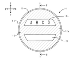
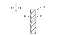
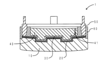
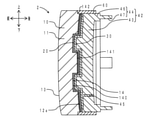
- FIG. 2 is a sectional view taken along line IV-IV of FIG. It is a partially enlarged view of the decorative film layer constituting the decorative molded body.
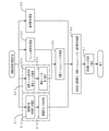
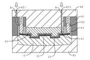
- It is a flowchart which shows the manufacturing process of the decorative molded article. It is a vertical sectional view of the molding die in a member arrangement process. It is a vertical sectional view of the molding die in the vacuum drawing process after a member arrangement process. It is a vertical sectional view of the mold compaction state of a molding die. It is a vertical sectional view of the molding die in a molding process.
- the decorative molded body of the present invention is embodied as an emblem placed in front of a radio wave radar device mounted on an automobile.
- the front-rear direction corresponds to the stacking direction and the front-back direction of the members.
- the decorative molded body 1 has a circular shape when viewed from the front.
- the decorative molded body 1 includes a transparent layer 10, a decorative film layer 20, a molding layer 30, a base material layer 40, a frame member 50, and a sealing member 60.
- the transparent layer 10 has a main body portion 11 and coating film portions 12a and 12b.
- the main body 11 is made of a polycarbonate resin and has a disk shape.
- the main body 11 has a front surface 13 that is visible from the front of the vehicle and a rear surface 14 that is arranged on the opposite side of the front surface 13 in the front-rear direction.
- the front surface 13 is included in the concept of a surface in the present invention.
- the rear surface 14 is included in the concept of the back surface in the present invention.
- the front surface 13 has a curved surface shape that is slightly curved forward.
- a hard coat layer (not shown) is formed on the front surface 13 to prevent scratches.
- the rear surface 14 has a concave portion 140, a convex portion 141, and a notch portion 142.
- the recess 140 has a groove shape extending in the left-right direction.
- the notch 142 is formed in a concave shape on the entire peripheral edge of the rear surface 14.
- the convex portion 141 is a portion other than the concave portion 140 and the notch portion 142.
- the rear surface 14 has an uneven shape due to the concave portion 140 and the convex portion 141.
- the coating film portion 12a is arranged on the entire convex portion 141 of the rear surface 14.
- the coating film portion 12a corresponds to the dotted line hatched portion in FIG.
- the coating film portion 12b is arranged in a part of the recess 140 of the rear surface 14.
- the coating film portion 12b corresponds to the character portion of "ABCD" when viewed from the front.
- the coating film portions 12a and 12b are made of a black acrylic evaporative drying type paint. The coating film portions 12a and 12b pass through the transparent layer 10 and are visually recognized as black from the front.
- the decorative film layer 20 is arranged behind the transparent layer 10.
- the decorative film layer 20 is arranged so as to follow the uneven shape of the rear surface 14 of the transparent layer 10.
- the decorative film layer 20 is sandwiched between the transparent layer 10 and the molding layer 30 described later, and is in close contact with the transparent layer 10.
- the decorative film layer 20 has a resin film 21 and a decorative layer 22.
- the resin film 21 is made of acrylic resin.
- the decorative layer 22 is an indium film and is formed on the front surface of the resin film 21.
- the decorative film layer 20 passes through the transparent layer 10 and is visually recognized from the front in the portion where the coating film portions 12a and 12b are not arranged. That is, the metallic luster of the decorative layer 22 is visually recognized from the front.
- the molded layer 30 is arranged behind the decorative film layer 20.
- the molded layer 30 is arranged so as to follow the uneven shape of the decorative film layer 20, and is arranged so as to surround the outer periphery of the base material layer 40 described later.
- the molded layer 30 is in close contact with the decorative film layer 20 and the base material layer 40.
- the molded layer 30 has a bottomed tubular shape when viewed from the rear, and the uneven shape of the rear surface 14 of the transparent layer 10 appears on the bottom (central portion).
- the molded layer 30 is made of a thermosetting material having silicone rubber.
- the thermosetting material can be molded at a temperature lower than the whitening temperature of indium.
- the base material layer 40 is arranged on the back side of the molded layer 30.
- the base material layer 40 is housed in the bottom of the bottomed cylindrical molded layer 30.
- the base material layer 40 is made of a polycarbonate resin and has a disk shape.
- the front surface of the base material layer 40 has a convex portion corresponding to the concave portion 140 of the rear surface 14 of the transparent layer 10, and the rear surface is a smooth surface without unevenness.
- the rear surface has a curved surface having the same curvature as the front surface 13 of the transparent layer 10, in other words, the front surface 13 is offset rearward.
- the base material layer 40 and the decorative film layer 20 are fixed and integrated by the molding layer 30. As shown in FIGS.
- an injection hole 41 penetrating in the front-rear direction is formed in the lower center of the base material layer 40.
- the injection hole 41 is included in the concept of the injection portion in the present invention.
- the injection hole 41 is filled with a thermosetting material which is a molding material of the molding layer 30.
- a millimeter-wave radar 9 is installed behind the decorative molded body 1.
- the injection hole 41 is arranged outside the irradiation range of the radio wave emitted from the millimeter wave radar 9.
- the millimeter wave radar 9 is included in the concept of the radio wave radar device in the present invention.
- the frame member 50 is arranged so as to surround the outer periphery of the base material layer 40 via the molding layer 30.
- the frame member 50 is made of PBT (polybutylene terephthalate) resin.
- the frame member 50 has a frame main body 51 and a mounting portion 52.
- the frame body 51 has a ring shape.
- the frame body 51 is attached to the peripheral edge of the decorative film layer 20. That is, the peripheral edge portion of the decorative film layer 20 is sandwiched between the frame main body 51 and the transparent layer 10.
- the mounting portion 52 has a flat plate shape and protrudes from the rear surface of the frame main body 51.
- Four mounting portions 52 are arranged at equal intervals in the circumferential direction of the frame main body 51.
- the mounting portion 52 serves as a portion for mounting the decorative molded body 1 to a mating member such as a front grill.
- the sealing member 60 is arranged in a ring shape on the outer peripheral side of the frame member 50.
- the sealing member 60 is arranged in the notch 142 of the rear surface 14 of the transparent layer 10.
- the sealing member 60 covers the outer peripheral end surface of the decorative film layer 20.
- the sealing member 60 is made of a thermosetting material having the same silicone rubber as the molded layer 30.
- FIG. 6 shows a flowchart of the manufacturing process of the decorative molded product.
- the method for manufacturing the decorative molded body of the present embodiment includes a member preparation step (S1 to S4), a pasting step (S5), a member placement step (S6), and a molding step (S7). ) And.
- the transparent layer 10 is manufactured (S1). Specifically, after the main body 11 is manufactured by injection molding and a hard coat layer is formed on the front surface 13 by painting (S1a), the coating film portions 12a and 12b are screened at predetermined positions on the rear surface 14 of the main body 11. It is formed by printing (S1b). At the same time, a flat decorative film body 200 is manufactured (S2). Specifically, as the material of the decorative film body 200, a strip-shaped sheet in which the resin film 21 and the decorative layer 22 are laminated is manufactured (S2a), and the strip-shaped sheet is cut out into a predetermined shape (S2b). In parallel, the frame member 50 is manufactured by injection molding (S3). In parallel, the base material layer 40 is manufactured by injection molding (S4).
- the decorative film body 200 is attached to the frame member 50 to manufacture the decorative film unit 53 (S5).
- the manufactured transparent layer 10, the decorative film unit 53, and the base material layer 40 are arranged in a molding die (S6).
- the molding layer 30 is molded from the thermosetting material, and the decorative film layer 20, the base material layer 40, and the frame member 50 are integrated (S7).
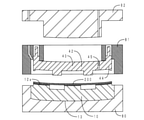
- FIG. 7 shows a vertical sectional view of the molding die in the member arranging process.
- FIG. 8 shows a vertical sectional view of the molding die in the evacuation step after the member arranging step.
- the lower die 80, the middle die 81, and the upper die 82 are used as the molding die.
- the lower mold 80, the middle mold 81, and the upper mold 82 are preheated to 80 to 120 ° C., which is equal to or lower than the indium whitening temperature.
- the transparent layer 10 is arranged on the lower mold 80 with the front surface 13 facing the mold surface side (lower side).
- the decorative film unit 53 and the base material layer 40 are arranged on the medium-sized 81.
- the decorative film unit 53 is arranged with the decorative film body 200 on the transparent layer 10 side (lower side).
- the decorative film body 200 is arranged while maintaining a flat surface.
- the base material layer 40 is arranged with the front surface having the convex portion facing the decorative film body 200 side (lower side).
- the medium mold 81 and the upper mold 82 are moved downward, and the upper mold 82 is brought into contact with the upper surface of the base material layer 40 of the medium mold 81.
- the decorative film body 200 remains flat. In this state, a vacuum is drawn between the transparent layer 10 arranged on the lower mold 80 and the decorative film body 200, and between the decorative film body 200 and the base material layer 40. As a result, the upper and lower regions of the decorative film body 200 are in a vacuum state.
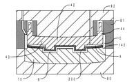
- FIG. 9 shows a vertical sectional view of the molded mold in a molded state.
- FIG. 10 shows a vertical sectional view of the molding die in the molding step.
- FIG. 11 shows a cross-sectional view in the stacking direction of the decorative molded product obtained after the mold is opened.
- FIG. 11 corresponds to FIG. 4 described above.
- the upper cavity A is formed by the medium-sized mold 81, the decorative film unit 53, and the base material layer 40.
- the lower cavity B is formed by the transparent layer 10 and the decorative film body 200.
- the outer peripheral cavity C is formed by the medium size 81, the notch 142 of the transparent layer 10, and the decorative film unit 53.
- the silicone rubber material R filled in the upper cavity A is cured by being heated and pressed by the molding dies 80, 81, 82 to become the molding layer 30.
- the molded layer 30 is in close contact with the decorative film layer 20, the base material layer 40, and the frame body 51. As a result, the decorative film layer 20, the base material layer 40, and the frame member 50 are integrated.
- the silicone rubber material R is injected through the sprue 821 of the upper mold 82.
- the injected silicone rubber material R is filled in the outer peripheral cavity C through the medium mold 81.
- the silicone rubber material R filled in the outer peripheral cavity C is cured by being heated and pressed by the molding dies 80, 81, 82 to become a sealing member 60.
- the mold is opened to manufacture the decorative molded body 1 as shown in FIG.
- the decorative molded body 1 of the present embodiment has a molded layer 30 between the decorative film layer 20 and the base material layer 40.
- the decorative film layer 20 is brought into close contact with the rear surface 14 of the transparent layer 10 having an uneven shape by utilizing the molding of the molded layer 30, and the base material layer 40 is integrated. Since heat and pressure are applied when the molding layer 30 is molded, the decorative film layer 20 follows the uneven shape and adheres even when the unevenness of the rear surface 14 of the transparent layer 10 is sharp.
- the decorative molded body 1 is excellent in design and radio wave transmission. Further, since the preform of the decorative film layer 20 is unnecessary and the layers can be fixed by one molding, the manufacturing man-hours can be reduced and the manufacturing cost can be suppressed. Further, as compared with the case where each layer is laminated in order, the steps of removing air and moisture can be reduced, and air and moisture are less likely to enter between the layers. In this respect as well, the decorative molded body 1 is excellent in radio wave transmission.
- the front surface of the base material layer 40 has a convex portion corresponding to the concave portion 140 of the rear surface 14 of the transparent layer 10, and the rear surface has a shape in which the front surface 13 of the transparent layer 10 is offset rearward.
- the base material layer 40 is arranged so as to fill the recesses, so that the transparent layer 10, the decorative film layer 20, the molded layer 30, and the molded layer 30 are arranged.
- the thickness (total thickness) of the laminate composed of the base material layer 40 is constant. In other words, the thickness of the portion through which the radio wave emitted from the millimeter wave radar 9 is transmitted becomes constant. Therefore, the decorative molded body 1 is excellent in radio wave transmission.
- the decorative molded body 1 has a frame member 50.
- the constituent members such as the transparent layer 10 are stably supported, and the decorative molded body 1 can be easily attached to the mating member.
- the molded layer 30 and the frame member 50 separate members, it is possible to select an appropriate material according to the function required for each member.
- the molded layer 30 is molded from a thermosetting material having silicone rubber and has viscoelasticity. The viscoelastic force of the molded layer 30 can firmly hold the base material layer 40 and the frame member 50. Further, since the impact resistance is enhanced by the presence of the molded layer 30, the transparent layer 10 is not easily cracked.
- the frame member 50 is made of PBT resin, it is possible to secure predetermined strength, heat resistance, wear resistance and the like.
- the decorative molded body 1 has a sealing member 60.
- the space between the transparent layer 10, the decorative film layer 20, and the frame body 51 is sealed, and the intrusion of air and moisture is effectively suppressed. Further, since the sealing member 60 covers the outer peripheral end surface of the decorative film layer 20, the designability is improved.
- the decorative film layer 200 which exhibits a flat shape by utilizing the molding of the molded layer 30 is used, and the decorative film layer which is in close contact with the rear surface 14 of the transparent layer 10 having an uneven shape. 20 is molded, and the base layer 40 is fixed by sandwiching the molded layer 30 between the molded decorative film layers 20.
- the decorative film body 200 can accurately follow the uneven shape of the rear surface 14 of the transparent layer 10. can. Therefore, according to the manufacturing method of the present embodiment, it is possible to manufacture the decorative molded body 1 having excellent design and radio wave transmission.
- the preform of the decorative film layer 20 is unnecessary, and the layers can be fixed by one molding, so that the manufacturing man-hours can be reduced and the cost can be reduced. can. Further, as compared with the case where each layer is laminated in order, the steps of removing air and moisture can be reduced, and air and moisture are less likely to enter between the layers. Therefore, according to the manufacturing method of the present embodiment, it is possible to manufacture the decorative molded body 1 having excellent radio wave transmission.
- the transparent layer 10, the decorative film unit 53, and the base material layer 40 are arranged in the molding dies 80, 81, 82, and the thermosetting material R is injected to perform integral molding. conduct.
- the total thickness of the decorative molded product 1 to be manufactured can be adjusted according to the state after molding. Further, even if there is a variation in thickness (molding error) in the decorative film body 200, the base material layer 40, etc., it can be absorbed by the cavities A and B, so that the total thickness of the decorative molded body 1 can be absorbed.
- the error can be constant.
- the thermosetting material R has silicone rubber and can be molded at an indium whitening temperature (about 120 to 150 ° C. or higher) or lower. Therefore, the decorative layer 22 (indium film) of the decorative film layer 20 is difficult to whiten.
- the transparent layer 10, the decorative film unit 53, and the base material layer 40 are manufactured separately.
- the process of manufacturing each is not performed in series by a series of lines, but is performed in parallel by separate lines. Therefore, the yield of the decorative molded body 1 can be increased as compared with the case where each step is performed in series.
- the decorative molded body 1 having the frame member 50 and having excellent design and radio wave transmission can be manufactured at low cost and with good yield by a simplified manufacturing process. can.
- the manufacturing method of the present embodiment by attaching the decorative film body 200 to the frame member 50 in advance, the displacement of the decorative film body 200 is suppressed and the placement on the medium size 81 becomes easy. Further, in consideration of appearance, it is necessary to prevent the decorative film layer 20 from protruding from the outer periphery of the decorative molded body 1. Normally, the protruding portion of the decorative film layer 20 is cut after the decorative molded body 1 is manufactured, but the cost is high because three-dimensional processing is required. According to the manufacturing method of the present embodiment, when the decorative film unit 53 is manufactured, the decorative film body 200 can be cut into a desired shape and then attached to the frame member 50. Therefore, it can be cut by relatively inexpensive processing, and the amount of waste of the decorative film body 200 can be reduced, which leads to cost reduction.
- the decorative film body 200 is cut out to be larger than the outer diameter of the frame body 51 and slightly protrudes from the frame body 51. Attach it in a state of being.
- the sealing member 60 it is possible to avoid deterioration of the design. That is, since the protruding portion of the decorative film body 200 is embedded when the sealing member 60 is molded, a good design can be realized.
- ⁇ Second embodiment> The difference between the decorative molded body of the present embodiment and the decorative molded body of the first embodiment is that the base material layer and the frame member are integrally made of the same material. Here, the differences will be mainly described.
- FIG. 12 shows a cross-sectional view in the stacking direction of the decorative molded product of the present embodiment.
- FIG. 12 corresponds to FIG. 4 above.
- the same members as those in FIG. 4 are indicated by the same reference numerals.
- the decorative molded body 2 includes a transparent layer 10, a decorative film layer 20, a molding layer 30, a back surface member 42, and a sealing member 60.
- the transparent layer 10, the decorative film layer 20, and the molded layer 30 are laminated in order from the front to the rear, as in the first embodiment.
- the molded layer 30 is made of a thermosetting material having silicone rubber, and is in close contact with the decorative film layer 20 and the back surface member 42.
- the sealing member 60 is made of a thermosetting material having the same silicone rubber as the molded layer 30, and is arranged in the notch 142 of the rear surface 14 of the transparent layer 10.
- the sealing member 60 is arranged in a ring shape on the outer peripheral side of the back surface member 42.
- the frame member 44 is arranged so as to surround the outer periphery of the base material layer 43.
- the frame member 44 has a frame main body 46 and a mounting portion 47.
- the frame body 46 has a ring shape.
- the mounting portion 47 has a flat plate shape and protrudes from the rear surface of the frame main body 46.
- Four mounting portions 47 are arranged at equal intervals in the circumferential direction of the frame main body 46.
- the manufacturing method of the present embodiment corresponds to a mode in which the base material layer and the frame member are an integral body (back surface member) in the second manufacturing method of the present invention. That is, in the method for manufacturing a decorative molded body of the present embodiment, a transparent layer is placed on a molding die with the surface facing the mold surface, and the decorative film body and the back surface member exhibit a flat shape in order from the transparent layer side.
- a heat-curable material for forming a molding layer is injected into a cavity formed between the decorative film body and the back surface member after the member arranging step of arranging the decorative film body and the back surface member, and the decorative film body is formed. It has a molding step of forming a decorative film layer and a molding layer along the uneven shape of the back surface of the transparent layer, and integrating the decorative film layer and the back surface member.
- the transparent layer 10 and the flat decorative film body 200 are prepared in the same manner as in the manufacturing method of the first embodiment. Further, the back surface member 42 is manufactured by injection molding (these correspond to the member preparation steps of the first embodiment).
- FIG. 13 shows a vertical sectional view of the molding die in the member arranging process.
- a lower die 80, a middle die 81, and an upper die 82 are used, and these are preheated to 80 to 120 ° C.
- the transparent layer 10 is arranged on the lower mold 80 with the front surface 13 facing the mold surface side (lower side).
- the decorative film body 200 is arranged on the upper side of the transparent layer 10 while maintaining the flatness.
- a back member 42 is arranged on the medium-sized 81.
- the back surface member 42 is arranged with the front surface of the base material layer 43 facing the decorative film body 200 side (lower side). After that, as in the first embodiment, the middle mold 81 and the upper mold 82 are moved downward, and the upper mold 82 is brought into contact with the upper surface of the back member 42 (base material layer 43) of the middle mold 81. In this state, a vacuum is drawn between the transparent layer 10 arranged on the lower mold 80 and the decorative film body 200, and between the decorative film body 200 and the back surface member 42. As a result, the upper and lower regions of the decorative film body 200 are in a vacuum state.
- the silicone rubber material R is injected through the sprue 821 of the upper mold 82.
- the injected silicone rubber material R is filled in the outer peripheral cavity C through the medium mold 81.
- the silicone rubber material R filled in the outer peripheral cavity C is cured by being heated and pressed by the molding dies 80, 81, 82 to become a sealing member 60.
- the mold is opened to manufacture the decorative molded body 2 shown in FIG. 12 above.
- the decorative molded article of the present embodiment and the method for producing the same have the same effect and effect with respect to the portion having a common configuration.
- the decorative molded body 2 of the present embodiment has a back surface member 42.
- the back surface member 42 is an integral body integrally molded from one material, and has a base material layer 43 and a frame member 44. Since the base material layer and the frame member are integrated, it is more difficult for moisture to enter as compared with the form in which each is a separate body. Further, by combining the base material layer and the frame member into one component, the number of components can be reduced and the cost can be reduced.
- the manufacturing process can be further simplified. Further, since one back member 42 may be arranged on the medium mold 81, the arrangement on the molding die (member arrangement step) becomes easy.
- the material of the transparent layer (main body) is not particularly limited as long as the transparency can be maintained, and may be a transparent resin material such as an acrylic resin, a polyethylene terephthalate (PET) resin, a transparent glass material, or the like, in addition to the polycarbonate resin in the above embodiment. ..
- the hard coat layer is formed on the surface of the main body, but the hard coat layer may not be present.
- another layer may be formed separately from the hard coat layer or in addition to the hard coat layer.
- the shape of the transparent layer is not particularly limited, and any shape such as an elliptical plate or a polygonal plate may be adopted in addition to the disk shape in the above embodiment.
- the surface of the transparent layer is curved to be convexly curved to the front side (front), but the surface shape may be a curved surface or flat surface to be concavely curved to the back side (rear).
- the uneven shape of the back surface of the transparent layer may be appropriately determined according to the design to be displayed.
- the concave portion is made to correspond to the glossy decorative portion (the portion where the decorative film layer is visible), and the convex portion is made to correspond to the black coating film portion, but the concave portion and the convex portion are opposite to each other. You may do it.
- the transparent layer does not necessarily have to have a coating film portion.
- the coating film portion is arranged on the entire convex portion and a part of the concave portion on the back surface, but may be arranged on only one of the convex portion and the concave portion, for example.
- the material and color of the coating film portion are not particularly limited.
- the method for manufacturing the coating film portion is also not particularly limited.
- the decorative film layer may be visible from the entire region, or may be partially masked by a coating film portion or the like and visible from only a partial region.
- the structure of the decorative film layer is not particularly limited, and may be a multi-layer structure composed of the resin film and the decorative layer shown in the above embodiment, or a single-layer structure composed of a single substance such as a resin film or a metal film.
- a non-stretchable PET resin or the like can be adopted as the resin film in addition to the acrylic resin.
- the resin film may be transparent or colored.
- the decorative layer may be formed on one side of the resin film or may be formed on both sides.
- a glossy metal material such as tin or gold or a resin material may be applied as the decorative layer.
- the decorative layer does not necessarily have to have gloss, and may be imparted with decorativeness by coloring or the like.
- the shape of the decorative film layer may be appropriately determined according to the shape of the transparent layer.
- the molding layer is molded from a thermosetting material.
- a thermosetting material in addition to the silicone rubber in the above embodiment, an epoxy resin, a phenol resin, or the like may be used. From the viewpoint of enhancing the holding power of the base material layer, a material having viscoelasticity such as silicone rubber is suitable as the thermosetting material.
- the thermosetting material may have an adhesive component, a coloring component, and the like in addition to the elastomer and resin components.
- thermosetting materials it is desirable to consider the molding temperature so that heating during molding does not adversely affect other members.
- the decorative film layer contains indium
- the thermosetting material is preferably a material that is liquid at room temperature or a material that is semi-solid.
- a translucent material is adopted as the thermosetting material, for example, a backlight is arranged on the back side of the decorative molded body, and the light is emitted to the base material layer, the molding layer, the decorative film layer, and the transparent. It is also possible to display the layer transparently.
- the surface of the molded layer exhibits an uneven shape along the uneven shape of the decorative film layer.
- the back surface may have the same uneven shape as the front surface, or may have a different shape such as a flat surface or a curved surface.
- the front surface of the base material layer may have a shape that follows the shape of the back surface of the molded layer, and the back surface has the same shape as the front surface of the transparent layer (a shape in which the front surface of the transparent layer is offset in the stacking direction).
- the material of the base material is not particularly limited as long as it can maintain predetermined strength, heat resistance, environmental resistance, chemical resistance, etc., and is not easily deformed during molding of the molded layer in addition to the polycarbonate (PC) resin in the above embodiment. From this point of view, examples thereof include high heat resistant AES resin having relatively high heat resistance among AES resins, high heat resistant ABS resin having relatively high heat resistance among ABS resins, and PC / ABS resin. Further, when the decorative molded body has a frame member, the base material layer and the frame member may be integrally molded from the same material as in the second embodiment.
- the base material layer Since the base material layer is arranged on the back side of the molded layer, it has an injection portion into which a thermosetting material is injected when the molded layer is molded.
- the shape, size, number, etc. of the injection portion are not particularly limited.
- a hole having an arbitrary shape such as the cylindrical hole shown in the above embodiment may be used, or a notch portion having an arbitrary shape may be used.
- Two or more injection portions may be formed.
- the injection portion When the radio wave radar device is arranged on the back side of the decorative molded body of the present invention, the injection portion may be arranged outside the irradiation range of the radio wave emitted from the radio wave radar device so as not to affect the transmission and reception of the radio wave. desirable.
- the radio wave radar device include millimeter wave radar and microwave radar.
- the decorative molded body has a frame member, but the frame member is not an essential member in the decorative molded body of the present invention.
- the material thereof is not particularly limited as long as it can maintain predetermined strength, heat resistance, environmental resistance, chemical resistance, etc., and examples thereof include high-strength PET resin in addition to the PBT resin in the above embodiment. ..
- the frame member may be transparent or colored. Further, as described above, the frame member and the base material layer may be integrally molded from the same material.
- the frame member may be configured to have a frame body and a mounting portion in consideration of mountability to the mating member.
- the shape of the frame body may be a shape corresponding to the outer peripheral shape of the transparent layer, but may be a different shape. Examples of the shape of the frame body include a circular frame shape (ring shape), an elliptical frame shape, and a polygonal frame shape.
- the mounting portion may be arranged so as to protrude from the back surface of the frame body, for example.
- the shape and number of the mounting portions are not particularly limited, and for example, a configuration having a locking claw, a locking hole, or the like may be used.
- the frame body In the function of the frame member to support the constituent member, it is desirable that the peripheral edge portion of the decorative film layer is sandwiched between the transparent layer and the frame member. In this case, as shown in the first embodiment, the frame body may be attached over the entire peripheral edge of the decorative film layer.
- the decorative molded body has a sealing member, but the sealing member is not an essential member in the decorative molded body of the present invention.
- the sealing member is not particularly limited as long as it has a sealing property.
- it may be manufactured from the same thermosetting material as the molded layer, such as silicone rubber, epoxy resin, and phenol resin. Alternatively, it may be manufactured from a thermoplastic material.
- the sealing member is arranged in a frame shape so as to cover the outer peripheral end surface of the decorative film layer.
- the color of the sealing member is not particularly limited, but in the above embodiment, since the sealing member is arranged in the notch on the back surface of the transparent layer, the sealing member is visually recognized through the transparent layer. In this case, by making the sealing member the same color as the coating film portion, the boundary between the sealing member and the coating film portion becomes difficult to see, and the designability is improved.
- the method for manufacturing a decorative molded body of the present invention includes a member placement step of arranging constituent members in a molding die, and a molding step of molding a decorative film layer into an uneven shape while molding a molding layer to integrate the constituent members. And have.
- the structure of the molding die is not limited to the above embodiment.
- the heating of the molding die may be appropriately adjusted according to the molding temperature of the thermosetting material which is the material of the molding layer. As shown in the above embodiment, when the decorative film layer contains indium, it is desirable to keep the molding die below the indium whitening temperature.
- the decorative film body is attached to the frame member in advance to manufacture the decorative film unit (attachment step), but the decorative film body is not attached to the frame member (decorative film). It may be placed in the mold as it is (without manufacturing the unit).
- the decorative film body when placed in the molding die may have a shape different from the shape in close contact with the back surface of the transparent layer (final shape as the decorative film layer).
- a flat decorative film body is used, but the shape of the decorative film body is not necessarily limited to a flat shape, and may be a curved shape or a shape having a slightly uneven shape.
- the decorative film body may be attached before or after the frame member is arranged in the medium size.
- the size of the decorative film body should be the same as or slightly larger than the outer shape of the frame body.
- constituent members such as a transparent layer are manufactured by injection molding.
- a liquid silicone rubber material was injection-molded to form a molded layer.
- the method for manufacturing the constituent members is not particularly limited.
- a semi-solid thermosetting material may be placed on the upper side of the decorative film body (base material layer side, upper cavity A in the above embodiment) and compression molded.
- the decorative molded body of the present invention can be used not only for emblems for vehicles such as automobiles, but also for emblems, key chains, straps, and the like attached to products. When used as a vehicle emblem, it may be placed on the front grill of the vehicle.
Landscapes
- Engineering & Computer Science (AREA)
- Mechanical Engineering (AREA)
- Injection Moulding Of Plastics Or The Like (AREA)
- Laminated Bodies (AREA)
- Vehicle Waterproofing, Decoration, And Sanitation Devices (AREA)
- Casting Or Compression Moulding Of Plastics Or The Like (AREA)
Abstract
加飾成形体(1)は、外部から視認される表面(13)と凹凸形状を有する裏面(14)とを有する透明層(10)と、該凹凸形状に沿うように透明層(10)の裏側に配置される加飾フィルム層(20)と、加飾フィルム層(20)の裏側に配置され熱硬化性材料からなる成形層(30)と、成形層(30)の裏側に配置される基材層(40)と、を備え、成形層(30)により透明層(10)、加飾フィルム層(20)、および基材層(40)が一体化されている。加飾成形体(1)の製造方法においては、熱硬化性材料による成形層(30)の成形時に、平面状の加飾フィルム体(200)を透明層(10)の裏面(14)の凹凸形状に沿わせながら加飾フィルム層(20)を成形すると共に基材層(40)を一体化する。
Description
本発明は、車両に装着される加飾成形体、特に電波レーダ装置から出射される電波の経路に配置される加飾成形体、およびその製造方法に関する。
自動車のフロントグリルには、金属光沢を有するエンブレムが配置されることが多い。また、ACC(アダプティブクルーズコントロール、定速走行・車間距離制御装置)が搭載される場合には、フロントグリルの背面側に、車間距離や障害物などとの距離を測定するための電波レーダ装置が配置される。この場合、電波レーダ装置は、エンブレムの背面側に配置され、エンブレムを介して電波を送受信する。このため、エンブレムには意匠性と共に電波透過性が要求される。
例えば特許文献1、2には、電波透過カバーとして、電波透過性を有する加飾成形体が記載されている。この種の加飾成形体は、特許文献1の図1、図2に記載されているように、表側(車両前方側)から透明層、加飾層、および基材層が積層された積層構造を有している。透明層の表面は平面形状を有し、裏面は凹凸形状を有している。加飾層は、透明層の凹凸形状に沿うように配置されている。加飾層は、透明層を通して外部から視認される。加飾層が凹凸形状を有することにより、加飾成形体において意匠が立体的に表示される。基材層は、裏側から加飾層を挟むように配置されている。基材層は、透明層および加飾層による凹部を充填するように配置される。これにより、透明層、加飾層、および基材層からなる積層体の厚さを一定にしている。
特許文献1に記載されている加飾成形体は、まず加飾層になるフィルムを真空成形により賦形し、次に賦形されたフィルムを成形型内に配置してフィルムの一面に透明層を成形し、最後にフィルムの他面に基材層を成形するという工程で製造されている(特許文献1の段落[0067]-[0072])。また、特許文献2に記載されている加飾成形体は、まず透明層を射出成形し、次に透明層の裏面に加飾層を印刷、蒸着などの方法により形成し、最後に加飾層が形成された透明層をインサート材として基材層を射出成形するという工程で製造されている(特許文献2の段落[0023])。
加飾層を透明層の凹凸形状に沿うように透明層の裏面に密着して配置することは、意匠性、電波透過性の観点から重要である。しかしながら、凹凸がシャープな場合、蒸着、吹きつけなどの方法では、加飾層を精度良く形成することは難しい。また、真空成形により、平面形状のフィルムを凹凸形状に沿わせる方法もあるが、この方法でもフィルムを凹凸形状(特に凹部)に追従させることは難しい。また、特許文献1に記載されているように、フィルムを予め凹凸形状に賦形しておく方法があるが、プレフォームを行うと、製造工数が増加してコスト高になる。
加飾成形体において良好な電波透過性を実現するためには、電波が透過する部分の厚さを一定にすることが重要になる。例えば、透明層、加飾層、および基材層を個々に製造し、接着やはめ込みなどにより一体化させる場合、製造された層の厚さにばらつき(成形誤差)があるため、積層した際の総厚さが一定になりにくい。また、層間に空気、水分などが存在すると、その部分の誘電率の変化により電波透過性が低下するおそれがある。よって、良好な電波透過性を実現するためには、層間に空気、水分などが存在しないことも重要になる。このためには、各層を積層する工程で空気や水分が混入するのを排除しなければならず、工程ごとに真空引きなどの作業が必要になる。
さらに、製品としての加飾成形体の歩留まりを高くすることも重要である。不良品は、製造の工程ごとに発生する可能性がある。このため、一連の工程を直列的に行う場合には、製品の歩留まりが低くなるおそれがある。これを回避するためには、少なくとも一部の工程を並列的に行うことが望ましい。
本発明は、このような実状に鑑みてなされたものであり、電波透過性が良好な加飾成形体を提供することを課題とする。また、当該加飾成形体を低コストで製造する方法を提供することを課題とする。
(1)上記課題を解決するため、本発明の加飾成形体は、積層方向を表裏方向として、外部から視認される表面と凹凸形状を有する裏面とを有する透明層と、該凹凸形状に沿うように該透明層の裏側に配置される加飾フィルム層と、該加飾フィルム層の裏側に配置され熱硬化性材料からなる成形層と、該成形層の裏側に配置される基材層と、を備え、該成形層により該透明層、該加飾フィルム層、および該基材層が一体化されていることを特徴とする。
(2)本発明の加飾成形体の好適な製造方法の一つである第一の製造方法は、成形型に、前記表面を型面側にして前記透明層を配置し、該透明層側から順に、平面状を呈する加飾フィルム体と、前記基材層と、を配置する部材配置工程と、型締め後、該加飾フィルム体と該基材層との間に形成されたキャビティに前記成形層を成形するための前記熱硬化性材料を注入し、該加飾フィルム体を該透明層の前記裏面の凹凸形状に沿わせながら前記加飾フィルム層および該成形層を成形すると共に、該成形層を介して該透明層および該加飾フィルム層に該基材層を一体化する成形工程と、を有することを特徴とする。
(3)本発明の加飾成形体の第二の製造方法は、本発明の加飾成形体がフレーム部材を有する形態の好適な製造方法のうちの一つ目の製造方法であって、成形型に、前記表面を型面側にして前記透明層を配置し、該透明層側から順に、平面状を呈する加飾フィルム体と、前記基材層と、を配置し、さらに該基材層の周縁部に前記フレーム部材を配置する部材配置工程と、型締め後、該加飾フィルム体と該基材層との間に形成されたキャビティに前記成形層を成形するための前記熱硬化性材料を注入し、該加飾フィルム体を該透明層の前記裏面の凹凸形状に沿わせながら前記加飾フィルム層および該成形層を成形すると共に、該成形層を介して該透明層および該加飾フィルム層に該基材層および該フレーム部材を一体化する成形工程と、を有することを特徴とする。
(4)本発明の加飾成形体の第三の製造方法は、本発明の加飾成形体がフレーム部材を有する形態の好適な製造方法のうちの二つ目の製造方法であって、前記フレーム部材に平面状を呈する加飾フィルム体を貼着し加飾フィルムユニットを製造する貼着工程と、成形型に、前記表面を型面側にして前記透明層を配置し、該加飾フィルム体を該透明層側にして該加飾フィルムユニットを配置し、該フレーム部材の内側に前記基材層を配置する部材配置工程と、型締め後、該加飾フィルム体と該基材層との間に形成されたキャビティに前記成形層を成形するための前記熱硬化性材料を注入し、該加飾フィルム体を該透明層の前記裏面の凹凸形状に沿わせながら前記加飾フィルム層および該成形層を成形すると共に、該成形層を介して該透明層、該加飾フィルム層、および該フレーム部材に該基材層を一体化する成形工程と、を有することを特徴とする。
(1)本発明の加飾成形体は、加飾フィルム層と基材層との間に成形層を有する。成形層は、熱硬化性材料から成形される。成形層の成形時に加えられる熱および圧力により、透明層の裏面の凹凸形状に沿うように透明層に密着した加飾フィルム層が成形されると共に、基材層が加飾フィルム層に一体化される。
本発明の加飾成形体においては、成形層の成形を利用して、凹凸形状を有する透明層の裏面に加飾フィルム層を密着させ、さらに基材層を含めた層同士を固定している。成形時に熱および圧力が加わるため、凹凸がシャープな場合でも、透明層の裏面の凹凸形状に追従した加飾フィルム層が得られる。これにより、加飾成形体の意匠性が向上する。また、加飾フィルム層の形状追従性を高めて透明層に密着させることにより、透明層と加飾フィルム層との間の空隙を極力無くすことができるため、電波透過性が向上する。また、加飾フィルム層を予め透明層の凹凸形状に賦形するためのプレフォームは不要であり、層同士の固定を一回の成形で行うことができるため、製造工数を少なくすることができコストを削減することができる。また、各層を順に積層させる場合と比較して、空気や水分を除去する工程を減らすことができるし、層間に空気および水分が侵入しにくい。よって、加飾成形体の電波透過性が向上する。
本発明の加飾成形体は基材層を有する。よって、透明層および加飾フィルム層による凹凸形状が成形層の裏面に現れていても、当該凹部を充填するように基材層を配置することにより、透明層、加飾フィルム層、成形層、および基材層からなる積層体の厚さ(総厚さ)を一定にすることができる。これにより、電波レーダ装置から出射される電波が透過する部分の厚さが一定になるため、本発明の加飾成形体においては、良好な電波透過性が実現される。
ちなみに、特許文献3には、表層部、該表層部と同材質の中層部、および裏層部を備える車両用電波透過部品が記載されている。特許文献3に記載されている電波透過部品(加飾成形体)は、まず表層部を射出成形した後、裏面の凹部に着色による加飾を施し、次に表層部と、表層部と同じ材料からなるシート材とを成形型内に配置して、最後にシート材側から裏層部を射出成形するという工程で製造されている(特許文献3の段落[0026]-[0028])。特許文献3に記載されている製造方法によると、裏層部を射出成形する際の圧力により、シート材が表層部の凹凸形状に沿って成形され中層部になる。しかしながら、裏層部はAES樹脂(アクリロニトリル-EPDM-スチレン共重合体)またはABS樹脂(アクリロニトリル-ブタジエン-スチレン共重合体)からなり(段落[0025])、熱硬化性材料は使用されていない。また、特許文献3においては、電波透過性が悪い裏層部の厚さを薄くするという課題を解決するために、表層部と同材質の中層部を配置しているに過ぎない(段落[0007]、[0031])。すなわち、シート材(中層部)は、表層部と同じ材料からなり、加飾フィルム層ではない。特許文献3に記載されている加飾成形体は、透明層、加飾フィルム層、成形層、および基材層を有する本発明の加飾成形体とは、構成および製造方法が全く異なる。
(2)本発明の加飾成形体の第一の製造方法は、部材配置工程と成形工程とを有する。部材配置工程において、平面状を呈する加飾フィルム体を、透明層および基材層と共に成形型に配置する。ここで「加飾フィルム体」は、透明層の裏面形状に沿った凹凸状を呈する加飾フィルム層になる前の部材である。そして成形工程において、加飾フィルム体と基材層との間に形成されたキャビティに、熱硬化性材料を注入して成形層を成形する。これにより、平面状の加飾フィルム体は、透明層の凹凸形状に沿うように変形しながら透明層の裏面に密着して加飾フィルム層になる。同時に、成形層を介して基材層が一体化される。
本発明の第一の製造方法によると、成形層の成形を利用することにより、平面状を呈する加飾フィルム体を用いて、凹凸形状を有する透明層の裏面に密着した加飾フィルム層を成形すると共に、成形された加飾フィルム層に成形層を挟んで基材層を固定することができる。成形時に熱および圧力が加わるため、凹凸がシャープな場合でも、加飾フィルム体を透明層の裏面の凹凸形状に精度良く追従させることができる。結果、透明層と加飾フィルム層との間の空隙を極力無くすことができ、意匠性および電波透過性に優れる加飾成形体を製造することができる。また、加飾フィルム層のプレフォームは不要であり、層同士の固定を一回の成形で行うことができるため、製造工数を少なくすることができコストを削減することができる。また、各層を順に積層させる場合と比較して、空気や水分を除去する工程を減らすことができるし、層間に空気および水分が侵入しにくい。これにより、電波透過性に優れる加飾成形体を製造することができる。
本発明の第一の製造方法によると、透明層、加飾フィルム体、および基材層を成形型に配置した状態で、熱硬化性材料を注入して一体成形を行う。この場合、型締め後の状態により、加飾成形体の総厚さを調整することができる。また、仮に加飾フィルム体、基材層などに厚さのばらつき(成形誤差)がある場合でも、それをキャビティで吸収することができるため、加飾成形体の総厚さを一定にすることができる。結果、電波透過性に優れる加飾成形体を製造することができる。
本発明の第一の製造方法によると、透明層、加飾フィルム体、基材層を予め製造しておく。ここで、各々を製造する工程は、一連のラインにより直列的に行う必要はなく、別々のラインで並列的に行うことができる。したがって、各工程を直列的に行う場合と比較して、製品としての加飾成形体の歩留まりを高くすることができる。
(3)本発明の加飾成形体の第二の製造方法は、上記第一の製造方法の一形態であり、フレーム部材を有する加飾成形体の製造方法である。すなわち、部材配置工程において、平面状を呈する加飾フィルム体を、透明層および基材層と共に成形型に配置すると共に、基材層の周縁部にフレーム部材を配置する。そして成形工程において、加飾フィルム体と基材層との間に形成されたキャビティに、熱硬化性材料を注入して成形層を成形する。これにより、平面状の加飾フィルム体は、透明層の凹凸形状に沿うように変形しながら透明層の裏面に密着して加飾フィルム層になる。同時に、成形層を介して基材層およびフレーム部材が一体化される。
フレーム部材は、透明層などの構成部材を支持する機能を有すると共に、加飾成形体を相手部材に取り付けるための部材としての機能を有する。本発明の第二の製造方法によると、フレーム部材を有し意匠性および電波透過性に優れる加飾成形体を、第一の製造方法と同様に、簡略化された製造工程で低コストで製造することができる。
(4)本発明の加飾成形体の第三の製造方法は、上記第二の製造方法と同様に、フレーム部材を有する加飾成形体の製造方法である。本発明の第三の製造方法は、部材配置工程の前に、フレーム部材に加飾フィルム体を貼着し、予め加飾フィルムユニットを製造しておく点で本発明の第二の製造方法と異なる。すなわち、まずは貼着工程において、加飾フィルムユニットを製造する。次に部材配置工程において、加飾フィルムユニットを、透明層および基材層と共に成形型に配置する。そして成形工程において、加飾フィルム体と基材層との間に形成されたキャビティに、熱硬化性材料を注入して成形層を成形する。これにより、平面状の加飾フィルム体は、透明層の凹凸形状に沿うように変形しながら透明層の裏面に密着して加飾フィルム層になる。同時に、成形層を介して基材層が一体化される。
本発明の第三の製造方法によると、フレーム部材を有し意匠性および電波透過性に優れる加飾成形体を、第二の製造方法と同様に、簡略化された製造工程で低コストで製造することができる。さらに本発明の第三の製造方法によると、予め加飾フィルム体をフレーム部材に貼着しておくことで、加飾フィルム体のずれが抑制され成形型への配置が容易になる。また、見栄えを考慮すると、加飾成形体の外周から加飾フィルム層がはみ出さないようにする必要がある。通常は、加飾成形体の製造後に加飾フィルム層のはみ出し部分を切断するが、三次元加工が必要になるなどしてコスト高になる。本発明の第三の製造方法によると、加飾フィルム体を所望の形状に切断してからフレーム部材に貼着すればよい。よって、比較的安価な加工で切断することができ、加飾フィルム体の廃棄量を低減することもできるため、コスト削減につながる。
本発明の加飾成形体およびその製造方法の実施の形態について説明する。実施の形態において、加飾成形体は、自動車に搭載される電波レーダ装置の前方に配置されるエンブレムとして具現化されている。以下の図においては、前後方向が部材の積層方向、表裏方向に対応している。
<第一実施形態>
[加飾成形体の構成]
まず、本実施形態の加飾成形体の構成について説明する。図1に、本実施形態の加飾成形体の斜視図を示す。図2に、同加飾成形体の正面図(前面図)を示す。図3に、同加飾成形体の背面図(後面図)を示す。図4に、図2のIV-IV断面図を示す。図5に、同加飾成形体を構成する加飾フィルム層の一部拡大図を示す。なお、説明の便宜上、図2においては、塗膜部に対応する部分のうち文字以外の部分に点線のハッチングを施している。
[加飾成形体の構成]
まず、本実施形態の加飾成形体の構成について説明する。図1に、本実施形態の加飾成形体の斜視図を示す。図2に、同加飾成形体の正面図(前面図)を示す。図3に、同加飾成形体の背面図(後面図)を示す。図4に、図2のIV-IV断面図を示す。図5に、同加飾成形体を構成する加飾フィルム層の一部拡大図を示す。なお、説明の便宜上、図2においては、塗膜部に対応する部分のうち文字以外の部分に点線のハッチングを施している。
図1~図4に示すように、加飾成形体1は、正面から見て円形を呈している。加飾成形体1は、透明層10と、加飾フィルム層20と、成形層30と、基材層40と、フレーム部材50と、封止部材60と、を備えている。
透明層10は、本体部11と塗膜部12a、12bとを有している。本体部11は、ポリカーボネート樹脂からなり、円板状を呈している。本体部11は、車両前方から視認される前面13と、前後方向において前面13と反対側に配置される後面14と、を有している。前面13は、本発明における表面の概念に含まれる。後面14は、本発明における裏面の概念に含まれる。前面13は、若干前方に凸状に湾曲した曲面状を呈している。前面13には、傷つきを防止するための図示しないハードコート層が形成されている。後面14は、凹部140と、凸部141と、切欠部142と、を有している。凹部140は、左右方向に延在する溝状を呈している。切欠部142は、後面14の周縁部全体に凹状に形成されている。凸部141は、凹部140および切欠部142以外の部分である。凹部140および凸部141により、後面14は凹凸状を呈している。
塗膜部12a、12bのうち、塗膜部12aは、後面14の凸部141全体に配置されている。塗膜部12aは、図2における点線ハッチング部分に対応している。塗膜部12bは、後面14の凹部140の一部に配置されている。塗膜部12bは、前方から見た場合の「ABCD」の文字部分に対応している。塗膜部12a、12bは、黒色のアクリル系蒸発乾燥型塗料からなる。塗膜部12a、12bは、透明層10を透過して前方から黒色に視認される。
加飾フィルム層20は、透明層10の後側に配置されている。加飾フィルム層20は、透明層10の後面14の凹凸形状に沿うように配置されている。加飾フィルム層20は、透明層10と後述する成形層30との間に挟持され、透明層10に密着している。加飾フィルム層20は、図5に示すように、樹脂フィルム21と加飾層22とを有している。樹脂フィルム21は、アクリル樹脂からなる。加飾層22は、インジウム膜であり、樹脂フィルム21の前面に形成されている。加飾フィルム層20は、塗膜部12a、12bが配置されていない部分において、透明層10を透過して前方から視認される。すなわち、前方から加飾層22の金属光沢が視認される。
成形層30は、加飾フィルム層20の後側に配置されている。成形層30は、加飾フィルム層20の凹凸形状に沿うように配置されると共に、後述する基材層40の外周を囲むように配置されている。成形層30は、加飾フィルム層20および基材層40に密着している。成形層30は後方から見て有底筒状を呈し、底部(中央部)には透明層10の後面14の凹凸形状が現れている。成形層30は、シリコーンゴムを有する熱硬化性材料からなる。当該熱硬化性材料は、インジウムの白化温度より低温で成形可能である。
基材層40は、成形層30の裏側に配置されている。基材層40は、有底筒状の成形層30の底部に収容されている。基材層40は、ポリカーボネート樹脂からなり、円板状を呈している。基材層40の前面は透明層10の後面14の凹部140に対応した凸部を有し、後面は凹凸が無い平滑面である。後面は、透明層10の前面13と同じ曲率を有する曲面状、換言すると、前面13を後方にオフセットした形状を呈している。基材層40と加飾フィルム層20とは、成形層30により固着され一体化されている。図3および図4に示すように、基材層40の中央下部には、前後方向に貫通する注入孔41が穿設されている。注入孔41は本発明における注入部の概念に含まれる。注入孔41には、成形層30の成形材料である熱硬化性材料が充填されている。加飾成形体1の後方には、ミリ波レーダ9が設置される。注入孔41は、ミリ波レーダ9から出射される電波の照射範囲外に配置されている。ミリ波レーダ9は、本発明における電波レーダ装置の概念に含まれる。
フレーム部材50は、成形層30を介して基材層40の外周を囲むように配置されている。フレーム部材50は、PBT(ポリブチレンテレフタレート)樹脂からなる。フレーム部材50は、フレーム本体51と、取付部52と、を有している。フレーム本体51は、リング状を呈している。フレーム本体51は、加飾フィルム層20の周縁部に貼着されている。すなわち、加飾フィルム層20の周縁部は、フレーム本体51と透明層10との間に挟持されている。取付部52は、平板状を呈しフレーム本体51の後面から突出している。取付部52は、フレーム本体51の周方向に等間隔で四つ配置されている。取付部52は、加飾成形体1をフロントグリルなどの相手部材に取り付けるための部位になる。
封止部材60は、フレーム部材50の外周側にリング状に配置されている。封止部材60は、透明層10の後面14の切欠部142に配置されている。封止部材60は、加飾フィルム層20の外周端面を覆っている。封止部材60は、成形層30と同じシリコーンゴムを有する熱硬化性材料からなる。
[加飾成形体の製造方法]
次に、本実施形態の加飾成形体の製造方法について説明する。本実施形態の製造方法は、本発明の第三の製造方法に対応している。図6に、加飾成形体の製造工程のフローチャートを示す。図6に示すように、本実施形態の加飾成形体の製造方法は、部材準備工程(S1~S4)と、貼着工程(S5)と、部材配置工程(S6)と、成形工程(S7)と、を有している。
次に、本実施形態の加飾成形体の製造方法について説明する。本実施形態の製造方法は、本発明の第三の製造方法に対応している。図6に、加飾成形体の製造工程のフローチャートを示す。図6に示すように、本実施形態の加飾成形体の製造方法は、部材準備工程(S1~S4)と、貼着工程(S5)と、部材配置工程(S6)と、成形工程(S7)と、を有している。
まず、透明層10を製造する(S1)。具体的には、本体部11を射出成形により製造し、その前面13にハードコート層を塗装により形成した(S1a)後、本体部11の後面14の所定位置に塗膜部12a、12bをスクリーン印刷により形成する(S1b)。並行して、平面状の加飾フィルム体200を製造する(S2)。具体的には、加飾フィルム体200の素材として、樹脂フィルム21と加飾層22とが積層された帯状シートを製造し(S2a)、それを所定形状に切り抜く(S2b)。並行して、フレーム部材50を射出成形により製造する(S3)。並行して、基材層40を射出成形により製造する(S4)。
次に、フレーム部材50に加飾フィルム体200を貼着して、加飾フィルムユニット53を製造する(S5)。それから、製造された透明層10、加飾フィルムユニット53、基材層40を成形型に配置する(S6)。そして、熱硬化性材料により成形層30を成形すると共に、加飾フィルム層20、基材層40、およびフレーム部材50を一体化する(S7)。
以下、部材配置工程(S6)および成形工程(S7)について図面を参照しながら説明する。まず、部材配置工程について説明する。図7に、部材配置工程における成形型の上下方向断面図を示す。図8に、部材配置工程後の真空引き工程における成形型の上下方向断面図を示す。図7に示すように、成形型としては、下型80、中型81、上型82を使用する。下型80、中型81、上型82は、予め、インジウムの白化温度以下である80~120℃に加温しておく。下型80には、透明層10を、前面13を型面側(下側)にして配置する。中型81には、加飾フィルムユニット53と基材層40とを配置する。加飾フィルムユニット53は、加飾フィルム体200を透明層10側(下側)にして配置する。加飾フィルム体200は、平面状が維持されたまま配置される。基材層40は、凸部を有する前面を加飾フィルム体200側(下側)にして配置する。なお、中型81を使用して、加飾フィルムユニット53の製造(フレーム部材50の製造および加飾フィルム体200の貼着)を行う場合には、中型81に予め配置されている加飾フィルムユニット53の内側に、基材層40を配置すればよい。それから、図8に白抜き矢印で示すように、中型81および上型82を下方に移動させ、上型82を中型81の基材層40の上面に接触させる。この段階では、加飾フィルム体200は平面状が維持されたままである。この状態において、下型80に配置された透明層10と加飾フィルム体200との間、および加飾フィルム体200と基材層40との間を真空引きする。これにより、加飾フィルム体200の上下領域は真空状態になる。
次に、成形工程について説明する。図9に、成形型の型締め状態の上下方向断面図を示す。図10に、成形工程における成形型の上下方向断面図を示す。図11に、型開き後に得られる加飾成形体の積層方向断面図を示す。図11は、前出の図4に対応している。まず、図9に示すように、下型80、中型81、上型82を型締めする。すると、加飾フィルム体200は、基材層40の下面(前面)の凸部に接触する。これにより、接触した部分は下方に凸状に変形する。型締め状態において、中型81、加飾フィルムユニット53、および基材層40により、上側キャビティAが形成される。透明層10および加飾フィルム体200により、下側キャビティBが形成される。中型81、透明層10の切欠部142、および加飾フィルムユニット53により、外周キャビティCが形成される。
次に、図10に白抜き矢印で示すように、上型82のスプルー820を通して、シリコーンゴム材料Rを注入する。シリコーンゴム材料Rは、常温において液状の材料であり、液状の状態で注入される。注入されたシリコーンゴム材料Rは、基材層40の注入孔41を通って上側キャビティAに充填される。ここで、下側キャビティBは真空状態である。よって、上側キャビティAにシリコーンゴム材料Rが充填されることにより、その圧力により加飾フィルム体200が下方に変形し、透明層10の後面14の凹凸形状に沿って密着して加飾フィルム層20になる。これにより、下側キャビティBが消滅する。また、上側キャビティAに充填されたシリコーンゴム材料Rは、成形型80、81、82により加熱、加圧されることにより硬化して、成形層30になる。成形層30は、加飾フィルム層20、基材層40およびフレーム本体51に密着する。これにより、加飾フィルム層20、基材層40、およびフレーム部材50が一体化される。
同時に、上型82のスプルー821を通して、シリコーンゴム材料Rを注入する。注入されたシリコーンゴム材料Rは、中型81を通って外周キャビティCに充填される。外周キャビティCに充填されたシリコーンゴム材料Rは、成形型80、81、82により加熱、加圧されることにより硬化して、封止部材60になる。最後に型開きして、図11に示すように、加飾成形体1が製造される。
[作用効果]
次に、本実施形態の加飾成形体およびその製造方法の作用効果について説明する。本実施形態の加飾成形体1は、加飾フィルム層20と基材層40との間に成形層30を有する。加飾成形体1においては、成形層30の成形を利用して、凹凸形状を有する透明層10の後面14に加飾フィルム層20を密着させると共に、基材層40を一体化している。成形層30を成形する際には熱および圧力が加わるため、透明層10の後面14の凹凸がシャープな場合でも、加飾フィルム層20は当該凹凸形状に追従して密着する。このため、透明層10と加飾フィルム層20との間に電波透過性に影響を与えるような空隙は無く、加飾成形体1は意匠性および電波透過性に優れる。また、加飾フィルム層20のプレフォームは不要であり、層同士の固定を一回の成形で行うことができるため、製造工数が少なくなり製造コストも抑えられる。また、各層を順に積層させる場合と比較して、空気や水分を除去する工程を減らすことができるし、層間に空気および水分が侵入しにくい。この点においても、加飾成形体1は、電波透過性に優れる。
次に、本実施形態の加飾成形体およびその製造方法の作用効果について説明する。本実施形態の加飾成形体1は、加飾フィルム層20と基材層40との間に成形層30を有する。加飾成形体1においては、成形層30の成形を利用して、凹凸形状を有する透明層10の後面14に加飾フィルム層20を密着させると共に、基材層40を一体化している。成形層30を成形する際には熱および圧力が加わるため、透明層10の後面14の凹凸がシャープな場合でも、加飾フィルム層20は当該凹凸形状に追従して密着する。このため、透明層10と加飾フィルム層20との間に電波透過性に影響を与えるような空隙は無く、加飾成形体1は意匠性および電波透過性に優れる。また、加飾フィルム層20のプレフォームは不要であり、層同士の固定を一回の成形で行うことができるため、製造工数が少なくなり製造コストも抑えられる。また、各層を順に積層させる場合と比較して、空気や水分を除去する工程を減らすことができるし、層間に空気および水分が侵入しにくい。この点においても、加飾成形体1は、電波透過性に優れる。
基材層40の前面は、透明層10の後面14の凹部140に対応した凸部を有し、後面は、透明層10の前面13を後方にオフセットした形状を呈している。この場合、成形層30の後面が凹凸形状を有していても、基材層40がその凹部を充填するように配置されるため、透明層10、加飾フィルム層20、成形層30、および基材層40からなる積層体の厚さ(総厚さ)は一定になる。換言すると、ミリ波レーダ9から出射される電波が透過する部分の厚さが一定になる。よって、加飾成形体1は、電波透過性に優れる。
加飾成形体1は、フレーム部材50を有する。これにより、透明層10などの構成部材が安定して支持されると共に、加飾成形体1の相手部材への取り付けが容易になる。また、成形層30とフレーム部材50とを別部材にすることにより、各部材に要求される機能に応じて、適切な材料を選択することができる。成形層30は、シリコーンゴムを有する熱硬化性材料から成形され、粘弾性を有する。成形層30の粘弾性力により、基材層40およびフレーム部材50を強固に保持することができる。また、成形層30の存在により耐衝撃性が高まるため、透明層10が割れにくい。他方、フレーム部材50は、PBT樹脂製であるため、所定の強度、耐熱性、耐摩耗性などを確保することができる。
加飾成形体1は、封止部材60を有する。これにより、透明層10、加飾フィルム層20、およびフレーム本体51の間が封止され、空気や水分の侵入が効果的に抑制される。また、封止部材60により、加飾フィルム層20の外周端面が被覆されるため、意匠性が向上する。
本実施形態の製造方法においては、成形層30の成形を利用することにより、平面状を呈する加飾フィルム体200を用いて、凹凸形状を有する透明層10の後面14に密着した加飾フィルム層20を成形すると共に、成形された加飾フィルム層20に成形層30を挟んで基材層40を固定する。成形層30の成形時に熱および圧力を加えることにより、透明層10の後面14の凹凸がシャープな場合でも、加飾フィルム体200を透明層10の後面14の凹凸形状に精度良く追従させることができる。よって、本実施形態の製造方法によると、意匠性および電波透過性に優れる加飾成形体1を製造することができる。また、上述したように、加飾フィルム層20のプレフォームは不要であり、層同士の固定を一回の成形で行うことができるため、製造工数を少なくすることができコストを削減することができる。また、各層を順に積層させる場合と比較して、空気や水分を除去する工程を減らすことができるし、層間に空気および水分が侵入しにくい。よって、本実施形態の製造方法によると、電波透過性に優れる加飾成形体1を製造することができる。
本実施形態の製造方法においては、透明層10、加飾フィルムユニット53、および基材層40を成形型80、81、82に配置した状態で、熱硬化性材料Rを注入して一体成形を行う。この場合、型締め後の状態により、製造される加飾成形体1の総厚さを調整することができる。また、仮に加飾フィルム体200、基材層40などに厚さのばらつき(成形誤差)がある場合でも、それをキャビティA、Bで吸収することができるため、加飾成形体1の総厚さを一定にすることができる。また、熱硬化性材料Rはシリコーンゴムを有し、インジウムの白化温度(120~150℃程度以上)以下で成形可能である。よって、加飾フィルム層20の加飾層22(インジウム膜)が白化しにくい。
本実施形態の製造方法によると、透明層10、加飾フィルムユニット53、基材層40、を別々に製造しておく。ここで、各々を製造する工程は、一連のラインにより直列的に行うのではなく、別々のラインで並列的に行う。このため、各工程を直列的に行う場合と比較して、加飾成形体1の歩留まりを高くすることができる。このように、本実施形態の製造方法によると、フレーム部材50を有し意匠性および電波透過性に優れる加飾成形体1を、簡略化された製造工程で低コストで歩留まりよく製造することができる。
さらに本実施形態の製造方法によると、予め加飾フィルム体200をフレーム部材50に貼着しておくことで、加飾フィルム体200のずれが抑制され中型81への配置が容易になる。また、見栄えを考慮すると、加飾成形体1の外周から加飾フィルム層20がはみ出さないようにする必要がある。通常は、加飾成形体1の製造後に加飾フィルム層20のはみ出し部分を切断するが、三次元加工が必要になるなどしてコスト高になる。本実施形態の製造方法によると、加飾フィルムユニット53を製造する際に、加飾フィルム体200を所望の形状に切断してからフレーム部材50に貼着することができる。よって、比較的安価な加工で切断することができ、加飾フィルム体200の廃棄量を低減することもできるため、コスト削減につながる。
なお、加飾フィルムユニット53を製造する場合、加飾フィルム体200を確実に固定するために、加飾フィルム体200をフレーム本体51の外径よりも大きめに切り抜いて、フレーム本体51から若干はみ出した状態で貼着する。しかし、封止部材60を配置することにより、意匠性の低下を回避することができる。すなわち、封止部材60の成形時に、加飾フィルム体200のはみ出し部分が埋設されるため、良好な意匠を実現することができる。
<第二実施形態>
本実施形態の加飾成形体と第一実施形態の加飾成形体との相違点は、基材層およびフレーム部材が同一材料からなる一体物である点である。ここでは、相違点を中心に説明する。
本実施形態の加飾成形体と第一実施形態の加飾成形体との相違点は、基材層およびフレーム部材が同一材料からなる一体物である点である。ここでは、相違点を中心に説明する。
[加飾成形体の構成]
図12に、本実施形態の加飾成形体の積層方向断面図を示す。図12は、前出図4に対応している。図12中、図4と同じ部材については同じ符号で示す。図12に示すように、加飾成形体2は、透明層10と、加飾フィルム層20と、成形層30と、背面部材42と、封止部材60と、を備えている。透明層10、加飾フィルム層20、成形層30は、第一実施形態と同様に、前方から後方に向かって順に積層されている。成形層30は、シリコーンゴムを有する熱硬化性材料からなり、加飾フィルム層20および背面部材42に密着している。封止部材60は、第一実施形態と同様に、成形層30と同じシリコーンゴムを有する熱硬化性材料からなり、透明層10の後面14の切欠部142に配置されている。封止部材60は、背面部材42の外周側にリング状に配置されている。
図12に、本実施形態の加飾成形体の積層方向断面図を示す。図12は、前出図4に対応している。図12中、図4と同じ部材については同じ符号で示す。図12に示すように、加飾成形体2は、透明層10と、加飾フィルム層20と、成形層30と、背面部材42と、封止部材60と、を備えている。透明層10、加飾フィルム層20、成形層30は、第一実施形態と同様に、前方から後方に向かって順に積層されている。成形層30は、シリコーンゴムを有する熱硬化性材料からなり、加飾フィルム層20および背面部材42に密着している。封止部材60は、第一実施形態と同様に、成形層30と同じシリコーンゴムを有する熱硬化性材料からなり、透明層10の後面14の切欠部142に配置されている。封止部材60は、背面部材42の外周側にリング状に配置されている。
背面部材42は、成形層30の裏側に配置されている。背面部材42は、成形層30により固着され一体化されている。背面部材42は、ポリカーボネート樹脂からなる一体物である。背面部材42は、基材層43とフレーム部材44とを有している。基材層43、フレーム部材44は、各々、第一実施形態の加飾成形体1における基材層40、フレーム部材50に対応している。
基材層43は、円板状を呈している。基材層43の前面は透明層10の後面14の凹部140に対応した凸部を有し、後面は凹凸が無い平滑面である。後面は、透明層10の前面13と同じ曲率を有する曲面状、換言すると、前面13を後方にオフセットした形状を呈している。基材層43の中央下部には、前後方向に貫通する注入孔45が穿設されている。注入孔45は本発明における注入部の概念に含まれる。注入孔45には、成形層30の成形材料である熱硬化性材料が充填されている。第一実施形態と同様に、注入孔45は、加飾成形体2の後方に配置されるミリ波レーダから出射される電波の照射範囲外に配置されている。
フレーム部材44は、基材層43の外周を囲むように配置されている。フレーム部材44は、フレーム本体46と、取付部47と、を有している。フレーム本体46は、リング状を呈している。取付部47は、平板状を呈しフレーム本体46の後面から突出している。取付部47は、フレーム本体46の周方向に等間隔で四つ配置されている。
[加飾成形体の製造方法]
次に、本実施形態の加飾成形体の製造方法について説明する。本実施形態の製造方法は、本発明の第二の製造方法において、基材層およびフレーム部材が一体物(背面部材)である形態に対応している。すなわち、本実施形態の加飾成形体の製造方法は、成形型に、表面を型面側にして透明層を配置し、該透明層側から順に、平面状を呈する加飾フィルム体および背面部材を配置する部材配置工程と、型締め後、該加飾フィルム体と該背面部材との間に形成されたキャビティに成形層を成形するための熱硬化性材料を注入し、該加飾フィルム体を該透明層の裏面の凹凸形状に沿わせながら加飾フィルム層および成形層を成形すると共に、該加飾フィルム層および該背面部材を一体化する成形工程と、を有する。
次に、本実施形態の加飾成形体の製造方法について説明する。本実施形態の製造方法は、本発明の第二の製造方法において、基材層およびフレーム部材が一体物(背面部材)である形態に対応している。すなわち、本実施形態の加飾成形体の製造方法は、成形型に、表面を型面側にして透明層を配置し、該透明層側から順に、平面状を呈する加飾フィルム体および背面部材を配置する部材配置工程と、型締め後、該加飾フィルム体と該背面部材との間に形成されたキャビティに成形層を成形するための熱硬化性材料を注入し、該加飾フィルム体を該透明層の裏面の凹凸形状に沿わせながら加飾フィルム層および成形層を成形すると共に、該加飾フィルム層および該背面部材を一体化する成形工程と、を有する。
本実施形態の製造方法においても、第一実施形態の製造方法と同様に、透明層10および平面状の加飾フィルム体200を準備する。また、背面部材42を射出成形により製造する(これらは、第一実施形態の部材準備工程に対応する)。
以下、部材配置工程および成形工程について、図面を参照しながら、第一実施形態との相違点を中心に説明する。まず、部材配置工程について説明する。図13に、部材配置工程における成形型の上下方向断面図を示す。図13に示すように、成形型としては、下型80、中型81、上型82を使用し、これらは予め80~120℃に加温しておく。下型80には、透明層10を、前面13を型面側(下側)にして配置する。そして、透明層10の上側に加飾フィルム体200を平面状を維持したまま配置する。中型81には、背面部材42を配置する。背面部材42は、基材層43の前面を加飾フィルム体200側(下側)にして配置する。この後、第一実施形態と同様に、中型81および上型82を下方に移動させ、上型82を中型81の背面部材42(基材層43)の上面に接触させる。この状態において、下型80に配置された透明層10と加飾フィルム体200との間、および加飾フィルム体200と背面部材42との間を真空引きする。これにより、加飾フィルム体200の上下領域は真空状態になる。
次に、成形工程について説明する。図14に、成形型の型締め状態の上下方向断面図を示す。図15に、成形工程における成形型の上下方向断面図を示す。まず、図14に示すように、下型80、中型81、上型82を型締めする。すると、加飾フィルム体200は、背面部材42の下面(前面)の凸部に接触する。加飾フィルム体200において、基材層43の凸部に押された部分は下方に凸状に変形する。型締め状態において、背面部材42および加飾フィルム体200により、上側キャビティAが形成される。透明層10および加飾フィルム体200により、下側キャビティBが形成される。中型81、透明層10の切欠部142、加飾フィルム体200、および背面部材42により、外周キャビティCが形成される。
次に、図15に示すように、上型82のスプルー820を通して、シリコーンゴム材料Rを注入する。注入されたシリコーンゴム材料Rは、背面部材42の注入孔45を通って上側キャビティAに充填される。ここで、下側キャビティBは真空状態である。よって、上側キャビティAにシリコーンゴム材料Rが充填されることにより、その圧力により加飾フィルム体200が下方に変形し、透明層10の後面14の凹凸形状に沿って密着して加飾フィルム層20になる。これにより、下側キャビティBが消滅する。また、上側キャビティAに充填されたシリコーンゴム材料Rは、成形型80、81、82により加熱、加圧されることにより硬化して、成形層30になる。成形層30は、加飾フィルム層20および背面部材42に密着する。これにより、加飾フィルム層20および背面部材42が一体化される。
同時に、上型82のスプルー821を通して、シリコーンゴム材料Rを注入する。注入されたシリコーンゴム材料Rは、中型81を通って外周キャビティCに充填される。外周キャビティCに充填されたシリコーンゴム材料Rは、成形型80、81、82により加熱、加圧されることにより硬化して、封止部材60になる。最後に型開きして、前出図12に示す加飾成形体2が製造される。
[作用効果]
次に、本実施形態の加飾成形体およびその製造方法の作用効果について説明する。本実施形態の加飾成形体およびその製造方法と、第一実施形態のそれとは、構成が共通する部分に関しては、同様の作用効果を有する。本実施形態の加飾成形体2は、背面部材42を有する。背面部材42は、一つの材料で一体的に成形された一体物であり、基材層43とフレーム部材44とを有する。基材層とフレーム部材とが一体化されているため、各々が別体である形態と比較して、水分がより侵入しにくい。また、基材層とフレーム部材とを一部品にすることにより、部品点数が少なくなり、コストを削減できることに加えて、第一実施形態のように加飾フィルム体をフレーム部材に貼着する必要もない。よって、本実施形態においては、製造工程をより簡略化することができる。また、中型81には一つの背面部材42を配置すればよいため、成形型への配置(部材配置工程)が容易になる。
次に、本実施形態の加飾成形体およびその製造方法の作用効果について説明する。本実施形態の加飾成形体およびその製造方法と、第一実施形態のそれとは、構成が共通する部分に関しては、同様の作用効果を有する。本実施形態の加飾成形体2は、背面部材42を有する。背面部材42は、一つの材料で一体的に成形された一体物であり、基材層43とフレーム部材44とを有する。基材層とフレーム部材とが一体化されているため、各々が別体である形態と比較して、水分がより侵入しにくい。また、基材層とフレーム部材とを一部品にすることにより、部品点数が少なくなり、コストを削減できることに加えて、第一実施形態のように加飾フィルム体をフレーム部材に貼着する必要もない。よって、本実施形態においては、製造工程をより簡略化することができる。また、中型81には一つの背面部材42を配置すればよいため、成形型への配置(部材配置工程)が容易になる。
<その他の形態>
以上、本発明の加飾成形体およびその製造方法の実施の形態について説明した。しかしながら、実施の形態は上記形態に特に限定されるものではない。当業者が行いうる種々の変形的形態、改良的形態で実施することも可能である。
以上、本発明の加飾成形体およびその製造方法の実施の形態について説明した。しかしながら、実施の形態は上記形態に特に限定されるものではない。当業者が行いうる種々の変形的形態、改良的形態で実施することも可能である。
[透明層]
透明層(本体部)の材質は、透明性を維持できれば特に限定されず、上記実施形態におけるポリカーボネート樹脂の他、アクリル樹脂、ポリエチレンテレフタレート(PET)樹脂などの透明樹脂材料、透明ガラス材料などでもよい。上記実施形態においては、本体部の表面にハードコート層を形成したが、ハードコート層は無くてもよい。本体部の材質に応じて、ハードコート層とは別の、またはハードコート層に加えて他の層を形成してもよい。
透明層(本体部)の材質は、透明性を維持できれば特に限定されず、上記実施形態におけるポリカーボネート樹脂の他、アクリル樹脂、ポリエチレンテレフタレート(PET)樹脂などの透明樹脂材料、透明ガラス材料などでもよい。上記実施形態においては、本体部の表面にハードコート層を形成したが、ハードコート層は無くてもよい。本体部の材質に応じて、ハードコート層とは別の、またはハードコート層に加えて他の層を形成してもよい。
透明層の形状は、特に限定されず、上記実施形態における円板状の他、楕円板状、多角形板状など任意の形状を採用すればよい。上記実施形態においては、透明層の表面を表側(前方)に凸状に湾曲した曲面状にしたが、表面形状は、裏側(後方)に凹状に湾曲した曲面状でも平面状でもよい。透明層の裏面の凹凸形状は、表示したい意匠に応じて適宜決定すればよい。上記実施形態においては、凹部を光沢を有する加飾部位(加飾フィルム層が視認可能な部位)に対応させ、凸部を黒色の塗膜部に対応させたが、凹部と凸部とを反対にしてもよい。
透明層は、必ずしも塗膜部を有しなくてもよい。上記実施形態においては、塗膜部を、裏面の凸部全体と凹部の一部とに配置したが、例えば凸部および凹部のいずれか一方のみに配置してもよい。塗膜部の材質、色などは特に限定されない。塗膜部の製造方法も特に限定されない。透明層においては、全領域から加飾フィルム層が視認できてもよく、塗膜部などにより部分的にマスキングされ一部領域のみから視認できてもよい。透明層の裏面形状と加飾フィルム層の視認可能領域とを組み合わせることにより、加飾成形体において種々の意匠を表示することができる。
[加飾フィルム層]
加飾フィルム層の構成は、特に限定されず、上記実施形態において示した樹脂フィルムと加飾層とからなる複層構造でも、樹脂フィルム、金属フィルムなどの単体からなる単層構造でもよい。加飾フィルム層を樹脂フィルムと加飾層とから構成する場合、樹脂フィルムとしては、アクリル樹脂の他、非延伸性PET樹脂などを採用することができる。樹脂フィルムは、透明でも着色されてもよい。加飾層は、樹脂フィルムの一面に形成されてもよく、両面に形成されてもよい。加飾層としては、インジウムの他、スズ、金などの光沢を有する金属材料または樹脂材料を適用してもよい。なお、加飾層は必ずしも光沢を有する必要はなく、着色などで加飾性が付与されてもよい。加飾フィルム層の形状は、透明層の形状に応じて適宜決定すればよい。
加飾フィルム層の構成は、特に限定されず、上記実施形態において示した樹脂フィルムと加飾層とからなる複層構造でも、樹脂フィルム、金属フィルムなどの単体からなる単層構造でもよい。加飾フィルム層を樹脂フィルムと加飾層とから構成する場合、樹脂フィルムとしては、アクリル樹脂の他、非延伸性PET樹脂などを採用することができる。樹脂フィルムは、透明でも着色されてもよい。加飾層は、樹脂フィルムの一面に形成されてもよく、両面に形成されてもよい。加飾層としては、インジウムの他、スズ、金などの光沢を有する金属材料または樹脂材料を適用してもよい。なお、加飾層は必ずしも光沢を有する必要はなく、着色などで加飾性が付与されてもよい。加飾フィルム層の形状は、透明層の形状に応じて適宜決定すればよい。
[成形層]
成形層は、熱硬化性材料により成形される。熱硬化性材料としては、上記実施形態におけるシリコーンゴムの他、エポキシ樹脂、フェノール樹脂などを有するものでもよい。基材層の保持力を高めるという観点から、熱硬化性材料としては、シリコーンゴムなどの粘弾性を有する材料が好適である。熱硬化性材料は、エラストマーおよび樹脂成分に加えて、接着成分、着色成分などを有してもよい。
成形層は、熱硬化性材料により成形される。熱硬化性材料としては、上記実施形態におけるシリコーンゴムの他、エポキシ樹脂、フェノール樹脂などを有するものでもよい。基材層の保持力を高めるという観点から、熱硬化性材料としては、シリコーンゴムなどの粘弾性を有する材料が好適である。熱硬化性材料は、エラストマーおよび樹脂成分に加えて、接着成分、着色成分などを有してもよい。
熱硬化性材料においては、成形時の加熱が他の部材に悪影響を及ぼさないよう、成形温度を考慮することが望ましい。例えば、加飾フィルム層にインジウムが含まれる場合には、インジウムの白化温度より低温で成形可能な材料を用いることが望ましい。この点においても、シリコーンゴムが好適である。成形性を考慮すると、熱硬化性材料は、常温で液状を呈する材料または半固体状を呈する材料が好適である。また、熱硬化性材料として、透光性を有する材料を採用すると、例えば加飾成形体の裏側にバックライトを配置して、その光を基材層、成形層、加飾フィルム層、および透明層を透過させて表示することも可能である。成形層の表面は、加飾フィルム層の凹凸形状に沿った凹凸状を呈する。他方裏面は、表面と同じ凹凸状でも、平面状、曲面状などの異なる形状でもよい。
[基材層]
本発明の加飾成形体においては、電波レーダ装置から出射される電波が透過する部分に相当する透明層、加飾フィルム層、成形層、および基材層からなる積層体の厚さ(総厚さ)が一定であることが望ましい。よって、基材層は、総厚さが一定になるように配置すればよい。基材層の表面は、成形層の裏面の形状に沿った形状でよく、裏面は透明層の表面と同じ形状(透明層の表面を積層方向にオフセットした形状)が望ましい。基材層の材質は、所定の強度、耐熱性、耐環境性、耐薬品性などを維持できれば特に限定されず、上記実施形態におけるポリカーボネート(PC)樹脂の他、成形層の成形時に変形しにくいという観点から、AES樹脂の中でも比較的耐熱性が高い高耐熱AES樹脂、ABS樹脂の中でも比較的耐熱性が高い高耐熱ABS樹脂、PC/ABS樹脂などが挙げられる。また、加飾成形体がフレーム部材を有する場合、第二実施形態のように、基材層とフレーム部材とを同一材料から一体的に成形してもよい。
本発明の加飾成形体においては、電波レーダ装置から出射される電波が透過する部分に相当する透明層、加飾フィルム層、成形層、および基材層からなる積層体の厚さ(総厚さ)が一定であることが望ましい。よって、基材層は、総厚さが一定になるように配置すればよい。基材層の表面は、成形層の裏面の形状に沿った形状でよく、裏面は透明層の表面と同じ形状(透明層の表面を積層方向にオフセットした形状)が望ましい。基材層の材質は、所定の強度、耐熱性、耐環境性、耐薬品性などを維持できれば特に限定されず、上記実施形態におけるポリカーボネート(PC)樹脂の他、成形層の成形時に変形しにくいという観点から、AES樹脂の中でも比較的耐熱性が高い高耐熱AES樹脂、ABS樹脂の中でも比較的耐熱性が高い高耐熱ABS樹脂、PC/ABS樹脂などが挙げられる。また、加飾成形体がフレーム部材を有する場合、第二実施形態のように、基材層とフレーム部材とを同一材料から一体的に成形してもよい。
基材層は成形層の裏側に配置されるため、成形層を成形する際に熱硬化性材料が注入される注入部を有する。注入部の形状、大きさ、数などは特に限定されない。例えば、上記実施形態において示した円筒状孔などの任意の形状の孔でもよいし、任意の形状の切欠部でもよい。注入部は、二つ以上形成されていてもよい。本発明の加飾成形体の裏側に電波レーダ装置が配置される場合、電波の送受信に影響を与えないよう、注入部は電波レーダ装置から出射される電波の照射範囲外に配置されることが望ましい。電波レーダ装置としては、ミリ波レーダ、マイクロ波レーダが挙げられる。
[フレーム部材]
上記実施形態においては、加飾成形体がフレーム部材を有する形態を示したが、本発明の加飾成形体において、フレーム部材は必須の部材ではない。フレーム部材を有する場合、その材質は、所定の強度、耐熱性、耐環境性、耐薬品性などを維持できれば特に限定されず、上記実施形態におけるPBT樹脂の他、高強度PET樹脂などが挙げられる。フレーム部材は、透明でも着色されてもよい。また、上述したように、フレーム部材と基材層とを同一材料から一体的に成形してもよい。
上記実施形態においては、加飾成形体がフレーム部材を有する形態を示したが、本発明の加飾成形体において、フレーム部材は必須の部材ではない。フレーム部材を有する場合、その材質は、所定の強度、耐熱性、耐環境性、耐薬品性などを維持できれば特に限定されず、上記実施形態におけるPBT樹脂の他、高強度PET樹脂などが挙げられる。フレーム部材は、透明でも着色されてもよい。また、上述したように、フレーム部材と基材層とを同一材料から一体的に成形してもよい。
フレーム部材は、相手部材への取り付け性を考慮して、フレーム本体と取付部とを有する構成にするとよい。フレーム本体の形状は、透明層の外周形状に対応する形状にすればよいが、異なる形状にしてもよい。フレーム本体の形状は、円形枠状(リング状)、楕円形枠状、多角形枠状などが挙げられる。取付部は、例えばフレーム本体の裏面から突出するよう配置すればよい。取付部の形状、数は特に限定されず、例えば、係止爪、係止穴などを有する構成にしてもよい。
構成部材を支持するというフレーム部材の機能において、加飾フィルム層の周縁部は、透明層とフレーム部材との間に挟持されることが望ましい。この場合、第一実施形態に示したように、フレーム本体は、加飾フィルム層の周縁部全周に亘って貼着されてもよい。
[封止部材]
上記実施形態においては、加飾成形体が封止部材を有する形態を示したが、本発明の加飾成形体において、封止部材は必須の部材ではない。封止部材を有する場合、その材質は、シール性を有するものであれば特に限定されない。例えば、シリコーンゴム、エポキシ樹脂、フェノール樹脂など、成形層と同じ熱硬化性材料で製造すればよい。あるいは、熱可塑性材料により製造してもよい。
上記実施形態においては、加飾成形体が封止部材を有する形態を示したが、本発明の加飾成形体において、封止部材は必須の部材ではない。封止部材を有する場合、その材質は、シール性を有するものであれば特に限定されない。例えば、シリコーンゴム、エポキシ樹脂、フェノール樹脂など、成形層と同じ熱硬化性材料で製造すればよい。あるいは、熱可塑性材料により製造してもよい。
封止部材は、加飾フィルム層の外周端面を覆うように枠状に配置される。封止部材の色は特に限定されないが、上記実施形態においては、封止部材を透明層の裏面の切欠部に配置したため、透明層を透過して封止部材が視認される。この場合、封止部材を塗膜部と同色にすることで、封止部材と塗膜部との境界が見えにくくなり、意匠性が向上する。
[製造方法]
本発明の加飾成形体の製造方法は、構成部材を成形型に配置する部材配置工程と、成形層を成形しながら加飾フィルム層を凹凸形状に成形し、構成部材を一体化する成形工程と、を有する。成形型の構成は、上記実施形態に限定されない。成形型の加熱については、成形層の材料である熱硬化性材料の成形温度に応じて適宜調整すればよい。上記実施形態に示したように、加飾フィルム層がインジウムを含む場合には、成形型をインジウムの白化温度以下に維持することが望ましい。
本発明の加飾成形体の製造方法は、構成部材を成形型に配置する部材配置工程と、成形層を成形しながら加飾フィルム層を凹凸形状に成形し、構成部材を一体化する成形工程と、を有する。成形型の構成は、上記実施形態に限定されない。成形型の加熱については、成形層の材料である熱硬化性材料の成形温度に応じて適宜調整すればよい。上記実施形態に示したように、加飾フィルム層がインジウムを含む場合には、成形型をインジウムの白化温度以下に維持することが望ましい。
第一実施形態においては、予めフレーム部材に加飾フィルム体を貼着して加飾フィルムユニットを製造したが(貼着工程)、加飾フィルム体をフレーム部材に貼着せずに(加飾フィルムユニットを製造せずに)、そのまま成形型に配置してもよい。成形型に配置される際の加飾フィルム体は、透明層の裏面に密着する形状(加飾フィルム層としての最終形状)とは異なる形状を有すればよい。上記実施形態においては平面状の加飾フィルム体を使用したが、加飾フィルム体の形状は、必ずしも平面状に限定されず、湾曲状や、若干凹凸状を有する形状などでもよい。また、加飾フィルムユニットを製造する場合、加飾フィルム体の貼着は、フレーム部材を中型に配置する前でも、配置した後でもよい。加飾フィルム体の大きさは、フレーム本体の外形と同じか少し大きめにするとよい。
上記実施形態においては、部材準備工程において、透明層などの構成部材を射出成形により製造した。また、液状のシリコーンゴム材料を射出成形して成形層を成形した。しかし、構成部材の製造方法は、特に限定されない。例えば成形層については、半固体状の熱硬化性材料を、加飾フィルム体の上側(基材層側、上記実施形態においては上側キャビティA)に配置して、圧縮成形してもよい。
[用途]
本発明の加飾成形体は、自動車などの車両用エンブレムの他、商品に付されるエンブレム、キーホルダー、ストラップなどにも用いることができる。車両用エンブレムとして用いる場合、車両のフロントグリルなどに配置すればよい。
本発明の加飾成形体は、自動車などの車両用エンブレムの他、商品に付されるエンブレム、キーホルダー、ストラップなどにも用いることができる。車両用エンブレムとして用いる場合、車両のフロントグリルなどに配置すればよい。
1:加飾成形体、2:加飾成形体、9:ミリ波レーダ、10:透明層、11:本体部、12a、12b:塗膜部、13:前面(表面)、14:後面(裏面)、20:加飾フィルム層、21:樹脂フィルム、22:加飾層、30:成形層、40:基材層、41:注入孔、42:背面部材、43:基材層、44:フレーム部材、45:注入孔、46:フレーム本体、47:取付部、50:フレーム部材、51:フレーム本体、52:取付部、53:加飾フィルムユニット、60:封止部材、80:下型、81:中型、82:上型、140:凹部、141:凸部、142:切欠部、200:加飾フィルム体、820、821:スプルー、A:上側キャビティ、B:下側キャビティ、C:外周キャビティ。
Claims (17)
- 積層方向を表裏方向として、
外部から視認される表面と凹凸形状を有する裏面とを有する透明層と、
該凹凸形状に沿うように該透明層の裏側に配置される加飾フィルム層と、
該加飾フィルム層の裏側に配置され熱硬化性材料からなる成形層と、
該成形層の裏側に配置される基材層と、
を備え、
該成形層により該透明層、該加飾フィルム層、および該基材層が一体化されていることを特徴とする加飾成形体。 - 前記基材層は、前記成形層を成形する際に前記熱硬化性材料が注入される注入部を有する請求項1に記載の加飾成形体。
- 前記基材層の裏側に電波レーダ装置が配置される場合に、
前記注入部は、該電波レーダ装置から出射される電波の照射範囲外に配置される請求項2に記載の加飾成形体。 - 前記熱硬化性材料は、シリコーンゴム、エポキシ樹脂、またはフェノール樹脂を有する請求項1ないし請求項3のいずれかに記載の加飾成形体。
- 前記加飾フィルム層は、樹脂フィルムと該樹脂フィルムに形成される加飾層とを有する請求項1ないし請求項4のいずれかに記載の加飾成形体。
- 前記加飾層はインジウム膜であり、
前記熱硬化性材料は、インジウムの白化温度より低温で成形可能な材料である請求項5に記載の加飾成形体。 - さらに、前記基材層の周縁部に配置されるフレーム部材を有する請求項1ないし請求項6のいずれかに記載の加飾成形体。
- 前記加飾フィルム層の周縁部は、前記透明層と前記フレーム部材との間に挟持される請求項7に記載の加飾成形体。
- 前記フレーム部材は、フレーム本体と、該フレーム本体の裏面から突出する取付部と、を有する請求項7または請求項8に記載の加飾成形体。
- 前記フレーム部材は、前記基材層と同一材料からなり、該基材層と一体的に成形されている請求項7ないし請求項9のいずれかに記載の加飾成形体。
- さらに、前記加飾フィルム層の外周端面を覆うように枠状に配置される封止部材を有する請求項1ないし請求項10のいずれかに記載の加飾成形体。
- 前記封止部材は、前記成形層と同一材料からなる請求項11に記載の加飾成形体。
- 電波レーダ装置から出射される電波を透過する車両用エンブレムである請求項1ないし請求項12のいずれかに記載の加飾成形体。
- 請求項1に記載の加飾成形体の製造方法であって、
成形型に、前記表面を型面側にして前記透明層を配置し、該透明層側から順に、平面状を呈する加飾フィルム体と、前記基材層と、を配置する部材配置工程と、
型締め後、該加飾フィルム体と該基材層との間に形成されたキャビティに前記成形層を成形するための前記熱硬化性材料を注入し、該加飾フィルム体を該透明層の前記裏面の凹凸形状に沿わせながら前記加飾フィルム層および該成形層を成形すると共に、該成形層を介して該透明層および該加飾フィルム層に該基材層を一体化する成形工程と、
を有することを特徴とする加飾成形体の製造方法。 - 請求項7に記載の加飾成形体の製造方法であって、
成形型に、前記表面を型面側にして前記透明層を配置し、該透明層側から順に、平面状を呈する加飾フィルム体と、前記基材層と、を配置し、さらに該基材層の周縁部に前記フレーム部材を配置する部材配置工程と、
型締め後、該加飾フィルム体と該基材層との間に形成されたキャビティに前記成形層を成形するための前記熱硬化性材料を注入し、該加飾フィルム体を該透明層の前記裏面の凹凸形状に沿わせながら前記加飾フィルム層および該成形層を成形すると共に、該成形層を介して該透明層および該加飾フィルム層に該基材層および該フレーム部材を一体化する成形工程と、
を有することを特徴とする加飾成形体の製造方法。 - 請求項7に記載の加飾成形体の製造方法であって、
前記フレーム部材に平面状を呈する加飾フィルム体を貼着し加飾フィルムユニットを製造する貼着工程と、
成形型に、前記表面を型面側にして前記透明層を配置し、該加飾フィルム体を該透明層側にして該加飾フィルムユニットを配置し、該フレーム部材の内側に前記基材層を配置する部材配置工程と、
型締め後、該加飾フィルム体と該基材層との間に形成されたキャビティに前記成形層を成形するための前記熱硬化性材料を注入し、該加飾フィルム体を該透明層の前記裏面の凹凸形状に沿わせながら前記加飾フィルム層および該成形層を成形すると共に、該成形層を介して該透明層、該加飾フィルム層、および該フレーム部材に該基材層を一体化する成形工程と、
を有することを特徴とする加飾成形体の製造方法。 - 前記基材層は、前記熱硬化性材料が注入される注入部を有し、
前記成形工程において、該熱硬化性材料は、該基材層に形成された該注入部を通って前記キャビティに注入される請求項14ないし請求項16のいずれかに記載の加飾成形体の製造方法。
Priority Applications (1)
| Application Number | Priority Date | Filing Date | Title |
|---|---|---|---|
| CN202180047635.5A CN115835944A (zh) | 2020-08-24 | 2021-08-05 | 装饰成形体及其制造方法 |
Applications Claiming Priority (2)
| Application Number | Priority Date | Filing Date | Title |
|---|---|---|---|
| JP2020-140898 | 2020-08-24 | ||
| JP2020140898A JP2022036602A (ja) | 2020-08-24 | 2020-08-24 | 加飾成形体およびその製造方法 |
Publications (1)
| Publication Number | Publication Date |
|---|---|
| WO2022044754A1 true WO2022044754A1 (ja) | 2022-03-03 |
Family
ID=80352304
Family Applications (1)
| Application Number | Title | Priority Date | Filing Date |
|---|---|---|---|
| PCT/JP2021/029090 Ceased WO2022044754A1 (ja) | 2020-08-24 | 2021-08-05 | 加飾成形体およびその製造方法 |
Country Status (3)
| Country | Link |
|---|---|
| JP (1) | JP2022036602A (ja) |
| CN (1) | CN115835944A (ja) |
| WO (1) | WO2022044754A1 (ja) |
Families Citing this family (2)
| Publication number | Priority date | Publication date | Assignee | Title |
|---|---|---|---|---|
| JP7619291B2 (ja) * | 2022-01-19 | 2025-01-22 | 豊田合成株式会社 | 樹脂成形品及び樹脂成形品の製造方法 |
| JP2024042283A (ja) * | 2022-09-15 | 2024-03-28 | 株式会社ファルテック | 複合部材、車両用外装部品及び複合部材製造方法 |
Citations (6)
| Publication number | Priority date | Publication date | Assignee | Title |
|---|---|---|---|---|
| JPH05155271A (ja) * | 1991-12-09 | 1993-06-22 | Nishikawa Kasei Co Ltd | 車両用内装パネル |
| JP2002301769A (ja) * | 2001-04-05 | 2002-10-15 | Johnson Controls Automotive Systems Corp | 車両用シートの表皮材の接着装置 |
| JP2014070899A (ja) * | 2012-09-27 | 2014-04-21 | Toyoda Gosei Co Ltd | 車両用ミリ波レーダ装置 |
| JP2016141355A (ja) * | 2015-02-05 | 2016-08-08 | 豊田合成株式会社 | 車両用電波透過カバー |
| WO2021084776A1 (ja) * | 2019-10-31 | 2021-05-06 | 住友理工株式会社 | 加飾成形体、加飾成形体の製造方法、及び、加飾成形体を用いた加工品の製造方法 |
| WO2021084775A1 (ja) * | 2019-10-31 | 2021-05-06 | 住友理工株式会社 | 加飾成形体及びその製造方法 |
-
2020
- 2020-08-24 JP JP2020140898A patent/JP2022036602A/ja active Pending
-
2021
- 2021-08-05 WO PCT/JP2021/029090 patent/WO2022044754A1/ja not_active Ceased
- 2021-08-05 CN CN202180047635.5A patent/CN115835944A/zh not_active Withdrawn
Patent Citations (6)
| Publication number | Priority date | Publication date | Assignee | Title |
|---|---|---|---|---|
| JPH05155271A (ja) * | 1991-12-09 | 1993-06-22 | Nishikawa Kasei Co Ltd | 車両用内装パネル |
| JP2002301769A (ja) * | 2001-04-05 | 2002-10-15 | Johnson Controls Automotive Systems Corp | 車両用シートの表皮材の接着装置 |
| JP2014070899A (ja) * | 2012-09-27 | 2014-04-21 | Toyoda Gosei Co Ltd | 車両用ミリ波レーダ装置 |
| JP2016141355A (ja) * | 2015-02-05 | 2016-08-08 | 豊田合成株式会社 | 車両用電波透過カバー |
| WO2021084776A1 (ja) * | 2019-10-31 | 2021-05-06 | 住友理工株式会社 | 加飾成形体、加飾成形体の製造方法、及び、加飾成形体を用いた加工品の製造方法 |
| WO2021084775A1 (ja) * | 2019-10-31 | 2021-05-06 | 住友理工株式会社 | 加飾成形体及びその製造方法 |
Also Published As
| Publication number | Publication date |
|---|---|
| CN115835944A (zh) | 2023-03-21 |
| JP2022036602A (ja) | 2022-03-08 |
Similar Documents
| Publication | Publication Date | Title |
|---|---|---|
| US11462824B2 (en) | Cover element | |
| CN107444289B (zh) | 车辆用装饰件 | |
| CN106476717B (zh) | 车辆用部件 | |
| US8974712B2 (en) | Method of manufacturing radome | |
| EP2853448B1 (en) | Decorative member for vehicle | |
| JP2019070650A (ja) | 自動車用レーダーセンサのためのカバー | |
| US20220227031A1 (en) | Method for manufacturing decorative molded body and method for manufacturing processed product using decorative molded body | |
| US20140093665A1 (en) | Decorative member for vehicle | |
| WO2022044754A1 (ja) | 加飾成形体およびその製造方法 | |
| US4985194A (en) | Method of making a decorative object having a notch-cut back side | |
| JP4771118B2 (ja) | 樹脂積層部材の製造方法 | |
| JP2010111011A (ja) | 車両用電波透過カバー、及び車両用電波透過カバーの製造方法 | |
| JP2001525741A (ja) | 共成型プロセスにおいて使用されるプラスチックフィルムの予成形方法ならびにこの方法を利用して製造される改良型のペイントフィルムによって被覆された部材 | |
| WO2018101165A1 (ja) | レーダカバー及びレーダカバーの製造方法 | |
| US20220234327A1 (en) | Decorative molded body and method for manufacturing the same | |
| JP2016150497A (ja) | 車両用加飾パネルの製造方法 | |
| CN111093934A (zh) | 用于车辆雷达的热塑性雷达罩的制造方法 | |
| CN118011325A (zh) | 用于车辆的雷达罩 | |
| WO2019064330A1 (ja) | 外装用加飾部品及び外装用加飾部品の製造方法 | |
| CN118369197A (zh) | 部件的注塑成型 | |
| EP3124197B1 (en) | Method for manufacturing a component for a motor-vehicle interior | |
| US20060244171A1 (en) | In-Mold Decoration process | |
| WO2021241089A1 (ja) | 車両用ガーニッシュ | |
| US20240198928A1 (en) | Emblem for vehicle with built-in heater and manufacturing method thereof | |
| EP3210743B1 (en) | Injection molded part with insert film |
Legal Events
| Date | Code | Title | Description |
|---|---|---|---|
| 121 | Ep: the epo has been informed by wipo that ep was designated in this application |
Ref document number: 21861182 Country of ref document: EP Kind code of ref document: A1 |
|
| NENP | Non-entry into the national phase |
Ref country code: DE |
|
| 122 | Ep: pct application non-entry in european phase |
Ref document number: 21861182 Country of ref document: EP Kind code of ref document: A1 |