WO2022044654A1 - 超音波診断装置および超音波診断装置の制御方法 - Google Patents
超音波診断装置および超音波診断装置の制御方法 Download PDFInfo
- Publication number
- WO2022044654A1 WO2022044654A1 PCT/JP2021/027704 JP2021027704W WO2022044654A1 WO 2022044654 A1 WO2022044654 A1 WO 2022044654A1 JP 2021027704 W JP2021027704 W JP 2021027704W WO 2022044654 A1 WO2022044654 A1 WO 2022044654A1
- Authority
- WO
- WIPO (PCT)
- Prior art keywords
- mammary gland
- breast
- ultrasonic
- ratio
- velocity value
- Prior art date
- Legal status (The legal status is an assumption and is not a legal conclusion. Google has not performed a legal analysis and makes no representation as to the accuracy of the status listed.)
- Ceased
Links
Images




Classifications
-
- A—HUMAN NECESSITIES
- A61—MEDICAL OR VETERINARY SCIENCE; HYGIENE
- A61B—DIAGNOSIS; SURGERY; IDENTIFICATION
- A61B8/00—Diagnosis using ultrasonic, sonic or infrasonic waves
- A61B8/52—Devices using data or image processing specially adapted for diagnosis using ultrasonic, sonic or infrasonic waves
- A61B8/5207—Devices using data or image processing specially adapted for diagnosis using ultrasonic, sonic or infrasonic waves involving processing of raw data to produce diagnostic data, e.g. for generating an image
-
- A—HUMAN NECESSITIES
- A61—MEDICAL OR VETERINARY SCIENCE; HYGIENE
- A61B—DIAGNOSIS; SURGERY; IDENTIFICATION
- A61B6/00—Apparatus or devices for radiation diagnosis; Apparatus or devices for radiation diagnosis combined with radiation therapy equipment
- A61B6/50—Apparatus or devices for radiation diagnosis; Apparatus or devices for radiation diagnosis combined with radiation therapy equipment specially adapted for specific body parts; specially adapted for specific clinical applications
- A61B6/502—Apparatus or devices for radiation diagnosis; Apparatus or devices for radiation diagnosis combined with radiation therapy equipment specially adapted for specific body parts; specially adapted for specific clinical applications for diagnosis of breast, i.e. mammography
-
- A—HUMAN NECESSITIES
- A61—MEDICAL OR VETERINARY SCIENCE; HYGIENE
- A61B—DIAGNOSIS; SURGERY; IDENTIFICATION
- A61B8/00—Diagnosis using ultrasonic, sonic or infrasonic waves
- A61B8/08—Clinical applications
- A61B8/0825—Clinical applications for diagnosis of the breast, e.g. mammography
-
- A—HUMAN NECESSITIES
- A61—MEDICAL OR VETERINARY SCIENCE; HYGIENE
- A61B—DIAGNOSIS; SURGERY; IDENTIFICATION
- A61B8/00—Diagnosis using ultrasonic, sonic or infrasonic waves
- A61B8/08—Clinical applications
- A61B8/0833—Clinical applications involving detecting or locating foreign bodies or organic structures
- A61B8/085—Clinical applications involving detecting or locating foreign bodies or organic structures for locating body or organic structures, e.g. tumours, calculi, blood vessels, nodules
-
- A—HUMAN NECESSITIES
- A61—MEDICAL OR VETERINARY SCIENCE; HYGIENE
- A61B—DIAGNOSIS; SURGERY; IDENTIFICATION
- A61B8/00—Diagnosis using ultrasonic, sonic or infrasonic waves
- A61B8/08—Clinical applications
- A61B8/0858—Clinical applications involving measuring tissue layers, e.g. skin, interfaces
-
- A—HUMAN NECESSITIES
- A61—MEDICAL OR VETERINARY SCIENCE; HYGIENE
- A61B—DIAGNOSIS; SURGERY; IDENTIFICATION
- A61B8/00—Diagnosis using ultrasonic, sonic or infrasonic waves
- A61B8/13—Tomography
- A61B8/14—Echo-tomography
-
- A—HUMAN NECESSITIES
- A61—MEDICAL OR VETERINARY SCIENCE; HYGIENE
- A61B—DIAGNOSIS; SURGERY; IDENTIFICATION
- A61B8/00—Diagnosis using ultrasonic, sonic or infrasonic waves
- A61B8/52—Devices using data or image processing specially adapted for diagnosis using ultrasonic, sonic or infrasonic waves
- A61B8/5215—Devices using data or image processing specially adapted for diagnosis using ultrasonic, sonic or infrasonic waves involving processing of medical diagnostic data
- A61B8/5223—Devices using data or image processing specially adapted for diagnosis using ultrasonic, sonic or infrasonic waves involving processing of medical diagnostic data for extracting a diagnostic or physiological parameter from medical diagnostic data
-
- A—HUMAN NECESSITIES
- A61—MEDICAL OR VETERINARY SCIENCE; HYGIENE
- A61B—DIAGNOSIS; SURGERY; IDENTIFICATION
- A61B8/00—Diagnosis using ultrasonic, sonic or infrasonic waves
- A61B8/54—Control of the diagnostic device
-
- G—PHYSICS
- G01—MEASURING; TESTING
- G01S—RADIO DIRECTION-FINDING; RADIO NAVIGATION; DETERMINING DISTANCE OR VELOCITY BY USE OF RADIO WAVES; LOCATING OR PRESENCE-DETECTING BY USE OF THE REFLECTION OR RERADIATION OF RADIO WAVES; ANALOGOUS ARRANGEMENTS USING OTHER WAVES
- G01S7/00—Details of systems according to groups G01S13/00, G01S15/00, G01S17/00
- G01S7/52—Details of systems according to groups G01S13/00, G01S15/00, G01S17/00 of systems according to group G01S15/00
- G01S7/52017—Details of systems according to groups G01S13/00, G01S15/00, G01S17/00 of systems according to group G01S15/00 particularly adapted to short-range imaging
- G01S7/52046—Techniques for image enhancement involving transmitter or receiver
- G01S7/52049—Techniques for image enhancement involving transmitter or receiver using correction of medium-induced phase aberration
-
- A—HUMAN NECESSITIES
- A61—MEDICAL OR VETERINARY SCIENCE; HYGIENE
- A61B—DIAGNOSIS; SURGERY; IDENTIFICATION
- A61B6/00—Apparatus or devices for radiation diagnosis; Apparatus or devices for radiation diagnosis combined with radiation therapy equipment
- A61B6/52—Devices using data or image processing specially adapted for radiation diagnosis
- A61B6/5211—Devices using data or image processing specially adapted for radiation diagnosis involving processing of medical diagnostic data
- A61B6/5217—Devices using data or image processing specially adapted for radiation diagnosis involving processing of medical diagnostic data extracting a diagnostic or physiological parameter from medical diagnostic data
-
- A—HUMAN NECESSITIES
- A61—MEDICAL OR VETERINARY SCIENCE; HYGIENE
- A61B—DIAGNOSIS; SURGERY; IDENTIFICATION
- A61B8/00—Diagnosis using ultrasonic, sonic or infrasonic waves
- A61B8/44—Constructional features of the ultrasonic, sonic or infrasonic diagnostic device
- A61B8/4427—Device being portable or laptop-like
-
- A—HUMAN NECESSITIES
- A61—MEDICAL OR VETERINARY SCIENCE; HYGIENE
- A61B—DIAGNOSIS; SURGERY; IDENTIFICATION
- A61B8/00—Diagnosis using ultrasonic, sonic or infrasonic waves
- A61B8/44—Constructional features of the ultrasonic, sonic or infrasonic diagnostic device
- A61B8/4444—Constructional features of the ultrasonic, sonic or infrasonic diagnostic device related to the probe
- A61B8/4472—Wireless probes
-
- A—HUMAN NECESSITIES
- A61—MEDICAL OR VETERINARY SCIENCE; HYGIENE
- A61B—DIAGNOSIS; SURGERY; IDENTIFICATION
- A61B8/00—Diagnosis using ultrasonic, sonic or infrasonic waves
- A61B8/46—Ultrasonic, sonic or infrasonic diagnostic devices with special arrangements for interfacing with the operator or the patient
- A61B8/467—Ultrasonic, sonic or infrasonic diagnostic devices with special arrangements for interfacing with the operator or the patient characterised by special input means
-
- A—HUMAN NECESSITIES
- A61—MEDICAL OR VETERINARY SCIENCE; HYGIENE
- A61B—DIAGNOSIS; SURGERY; IDENTIFICATION
- A61B8/00—Diagnosis using ultrasonic, sonic or infrasonic waves
- A61B8/56—Details of data transmission or power supply
Definitions
- the propagation time of ultrasonic waves is calculated based on the length of the ultrasonic path and the speed of sound in the medium in the subject. It is known that the difference between the sound velocity value used in this calculation and the actual sound velocity value in the medium causes deterioration of the resolution of the ultrasonic image. In the human body, the speed of sound is about 1550 m / s for the liver and the like, whereas it is 1420 m / s for fat, and has different values depending on the tissue. Therefore, in order to improve the resolution of the ultrasonic image, for example, as disclosed in Patent Document 1, a technique for changing the sound velocity value used for calculation in the fat layer and other layers has been developed.
- the ultrasonic diagnostic apparatus comprises an ultrasonic probe, an image acquisition unit that generates an ultrasonic image by transmitting and receiving an ultrasonic beam to a subject using the ultrasonic probe, and a breast of the subject. It is equipped with an initial condition setting unit that sets the basic sound velocity value for generating an ultrasonic image of the breast based on the ratio of breast glands in the breast calculated by analyzing the captured radiographic image, and the image acquisition unit is basic. It is characterized by generating an ultrasonic image of the breast using the sound velocity value.
- the ultrasonic diagnostic apparatus may include an input device for inputting the proportion of the mammary gland calculated by analyzing the radiographic image, and in this case, the initial condition setting unit is input via the input device.
- the basic sound velocity value can be set using the ratio of the mammary gland.
- the ultrasonic diagnostic apparatus can include an input device for inputting a radiographic image and a mammary gland ratio calculation unit that calculates the ratio of the mammary gland by analyzing the radiographic image input via the input device.
- the initial condition setting unit can set the basic sound velocity value using the mammary gland ratio calculated by the mammary gland ratio calculation unit.
- the ratio of the mammary gland the ratio of the volume of the mammary gland in the breast region to the volume of the breast in the breast region can be used. Further, the ratio of the mammary gland is preferably the ratio of the volume of the mammary gland in the mammary gland region to the volume of the breast in the mammary gland region.
- the ratio of the mammary gland may be expressed by the ratio R1 of the volume of the mammary gland in the breast region to the volume of the breast in the breast region and the ratio R2 of the thickness of the mammary layer in the breast region to the breast thickness in the breast region obtained by tomosynthesis.
- the initial condition setting unit determines the basic sound velocity value V1 (m / s) for the mammary gland as the ratio R1 (%) of the volume of the mammary gland and the ratio R2 (%) of the thickness of the mammary gland layer.
- the control method of the ultrasonic diagnostic apparatus of the present invention sets a basic sound velocity value for generating an ultrasonic image based on the ratio of breast glands in the breast calculated by analyzing a radiographic image obtained by photographing the breast of a subject. However, it is characterized in that an ultrasonic image of the breast is generated using the basic sound velocity value.
- the ultrasonic diagnostic apparatus is a basic sound velocity value for generating an ultrasonic image of a breast based on the ratio of breast glands in the breast calculated by analyzing a radiographic image of the breast of a subject. Since the image acquisition unit generates an ultrasonic image of the breast using the basic sound velocity value, the resolution of the ultrasonic image of the breast layer can be improved.
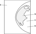
- Embodiment 1 of this invention It is a block diagram which shows the structure of the ultrasonic diagnostic apparatus which concerns on Embodiment 1 of this invention. It is a block diagram which shows the structure of the transmission / reception circuit in Embodiment 1 of this invention. It is a block diagram which shows the structure of the image generation part in Embodiment 1 of this invention. It is a figure which shows typically the example of the radiographic image used for the calculation of the ratio of a mammary gland. It is a figure which shows typically the example of the ultrasonic image generated in Embodiment 1 of this invention. It is a figure which shows typically the breast examined using the method of tomosynthesis. It is a block diagram which shows the structure of the ultrasonic diagnostic apparatus which concerns on Embodiment 2 of this invention.
- FIG. 1 shows the configuration of the ultrasonic diagnostic apparatus 1 according to the first embodiment of the present invention.
- the ultrasonic diagnostic apparatus 1 includes an ultrasonic probe 2 and a diagnostic apparatus main body 3.
- the ultrasonic probe 2 and the diagnostic device main body 3 are connected to each other by wireless communication.
- the ultrasonic probe 2 includes an oscillator array 11, and a transmission / reception circuit 12 and a probe-side wireless communication unit 13 are sequentially connected to the oscillator array 11. Further, the transmission / reception circuit 12 and the probe-side wireless communication unit 13 are connected to the probe control unit 16.
- main body control unit 29 is connected to the main body side wireless communication unit 21, the image generation unit 22, the display control unit 23, the initial condition setting unit 25, and the extraction unit 26.
- the input device 30 is connected to the main body control unit 29.
- main body side processor 31 is configured by the image generation unit 22, the display control unit 23, the initial condition setting unit 25, the extraction unit 26, and the main body control unit 29.
- the vibrator array 11 of the ultrasonic probe 2 shown in FIG. 1 has a plurality of ultrasonic vibrators arranged one-dimensionally or two-dimensionally. Each of these ultrasonic transducers transmits ultrasonic waves according to a drive signal supplied from the transmission / reception circuit 12, receives ultrasonic echoes from a subject, and outputs a signal based on the ultrasonic echoes.
- Each ultrasonic transducer is, for example, a piezoelectric ceramic represented by PZT (Lead Zirconate Titanate), a polymer piezoelectric element represented by PVDF (Poly Vinylidene Di Fluoride), and PMN-.
- PT Lead Magnesium Niobate-Lead Titanate: lead magnesiumidene fluoride-lead zirconate titanate
- the transmission / reception circuit 12 transmits ultrasonic waves from the vibrator array 11 under the control of the probe control unit 16 and generates a sound line signal based on the received signal acquired by the vibrator array 11.
- the transmission / reception circuit 12 includes a pulser 32 connected to the oscillator array 11, an amplification unit 33 sequentially connected in series from the oscillator array 11, an AD (Analog Digital) conversion unit 34, and a beam. It has a former 35.
- the pulsar 32 includes, for example, a plurality of pulse generators, and transmits from a plurality of ultrasonic oscillators of the oscillator array 11 based on a transmission delay pattern selected according to a control signal from the probe control unit 16.
- Each drive signal is supplied to a plurality of ultrasonic transducers by adjusting the delay amount so that the ultrasonic waves to be generated form an ultrasonic beam.
- the piezoelectric body expands and contracts, and the pulsed or continuous wave ultrasonic waves are generated from each ultrasonic vibrator. Is generated, and an ultrasonic beam is formed from the combined waves of those ultrasonic waves.
- the transmitted ultrasonic beam is reflected by, for example, a target such as a site of a subject, and propagates toward the vibrator array 11 of the ultrasonic probe 2.
- the ultrasonic echo propagating toward the oscillator array 11 in this way is received by each ultrasonic oscillator constituting the oscillator array 11.
- each ultrasonic vibrator constituting the vibrator array 11 expands and contracts by receiving the propagating ultrasonic echo, generates a received signal which is an electric signal, and amplifies these received signals. Output to 33.
- the amplification unit 33 amplifies the signal input from each ultrasonic vibrator constituting the vibrator array 11, and transmits the amplified signal to the AD conversion unit 34.
- the AD conversion unit 34 converts the signal transmitted from the amplification unit 33 into digital reception data.
- the beam former 35 gives a delay to each received data received from the main body side wireless communication unit 21 according to the basic sound velocity value V1 set by the initial condition setting unit 25, and adds the so-called reception focus. Perform processing. In the process of adding the respective delays to each received data, the ultrasonic waves emitted from the ultrasonic oscillators pass through the reflection points in the subject in each ultrasonic oscillator constituting the oscillator array 11.
- each received data converted by the AD conversion unit 34 is phase-adjusted and added, and a sound line signal in which the focus of the ultrasonic echo is narrowed down is acquired.
- the probe-side wireless communication unit 13 is composed of a circuit or the like including an antenna for transmitting and receiving radio waves, and under the control of the probe control unit 16, the probe-side wireless communication unit 13 and the main body-side wireless communication unit 21 of the diagnostic device main body 3 Perform wireless communication. At this time, the probe-side wireless communication unit 13 generates a transmission signal representing the sound line signal by modulating the carrier based on the sound line signal generated by the transmission / reception circuit 12, and diagnoses the generated transmission signal. Wireless transmission is performed to the main body side wireless communication unit 21 of the main body 3.
- the probe control unit 16 controls each unit of the ultrasonic probe 2 based on a program stored in advance. Further, although not shown, the ultrasonic probe 2 has a built-in battery that supplies electric power to each part of the ultrasonic probe 2.
- the main body side wireless communication unit 21 of the diagnostic apparatus main body 3 is configured by a circuit or the like including an antenna for transmitting and receiving radio waves like the probe side wireless communication unit 13, and is under the control of the main body control unit 29. Then, wireless communication is performed with the probe-side wireless communication unit 13 of the ultrasonic probe 2. At this time, the main body side wireless communication unit 21 demodulates the transmission signal wirelessly transmitted from the probe side wireless communication unit 13 to obtain a sound line signal. The main body side wireless communication unit 21 sends the obtained sound line signal to the image generation unit 22.
- the main body side wireless communication unit 21 generates a transmission signal representing the control information or the like by modulating the carrier based on the control information or the like for controlling the ultrasonic probe 2, and the generated transmission signal is used on the probe side. Wireless transmission is performed to the wireless communication unit 13.
- the carrier modulation method for example, ASK, PSK, QPSK, 16QAM and the like are used in the same manner as the modulation method used by the probe-side wireless communication unit 13.
- the image generation unit 22 has a configuration in which a signal processing unit 36, a DSC (Digital Scan Converter) 37, and an image processing unit 38 are sequentially connected in series.
- a signal processing unit 36 a DSC (Digital Scan Converter) 37
- an image processing unit 38 is sequentially connected in series.
- the signal processing unit 36 attenuates the sound line signal received from the main body side wireless communication unit 21 by a distance according to the depth of the ultrasonic reflection position using the basic sound velocity value V1 set by the initial condition setting unit 25. After the correction of the above, the envelope detection process is performed to generate a B-mode image signal which is tomographic image information about the tissue in the subject.
- the DSC 37 converts the B-mode image signal generated by the signal processing unit 36 into an image signal according to a normal television signal scanning method (raster conversion).
- the image processing unit 38 performs various necessary image processing such as gradation processing on the B mode image signal input from the DSC 37, and then sends the B mode image signal to the display control unit 23 and the extraction unit 26.
- the B-mode image signal that has been image-processed by the image processing unit 38 is simply referred to as an ultrasonic image.
- the display control unit 23 Under the control of the main body control unit 29, the display control unit 23 performs predetermined processing on the ultrasonic image or the like generated by the image generation unit 22 and displays it on the monitor 24.
- the monitor 24 performs various displays under the control of the display control unit 23.
- the monitor 24 includes, for example, a display device such as an LCD (Liquid Crystal Display) and an organic EL display (Organic Electroluminescence Display).
- the input device 30 inputs information on the proportion of breast glands in the breast, which is calculated by analyzing a radiographic image of the breast of the subject, to the diagnostic device main body 3 from an external device (not shown) such as a radiographic image diagnostic device. Is for.
- the input device 30 is composed of, for example, a device for a user to perform an input operation such as a keyboard, a mouse, a trackball, a touch pad, and a touch panel, and a connection terminal for inputting data from an external device (not shown). ..
- a radiographic image S in which the breast B of the subject is photographed by so-called mammography imaging as shown in FIG. 4 is used.
- mammography imaging the breast B of the subject is usually placed between the detector for detecting radiation and the radiation source, and the radiation emitted from the radiation source and attenuated through the breast B is emitted by the detector.
- a radiation image S composed of pixels corresponding to the intensity of the detected radiation is generated.
- the breast B of the subject differs in the proportion of mammary glands and the proportion of fat depending on the location. Therefore, each pixel in the radiographic image S has different luminances corresponding to the local transmittance of the breast B due to the proportion of mammary glands present and the proportion of fat present.
- the radiation image S is analyzed by the method disclosed in Japanese Patent Application Laid-Open No. 2010-253245, and the ratio of the presence of the mammary gland in the corresponding imaging location for each pixel of the radiation image S and the imaging location thereof.
- the thickness of the breast B calculating the volume of the mammary gland, and dividing the calculated volume of the mammary gland by the volume of the breast B, the proportion of the mammary gland in the breast B can be calculated.
- the volume of the breast B is the volume of the breast B in the breast region A, which is the entire region of the breast B shown in the radiographic image S.
- the initial condition setting unit 25 sets the basic sound velocity value V1 for generating an ultrasonic image of the breast B based on the information of the ratio of the mammary gland in the breast B of the subject input via the input device 30. ..
- the initial condition setting unit 25 stores the mammary gland sound velocity value V11 (m / s) determined for the mammary gland and the fat sound velocity value V12 (m / s) determined for the fat, for example, the subject.
- the proportion R (%) of the mammary gland in the breast B the mammary gland sound velocity value V11 (m / s) and the fat sound velocity value V12 (m / s)
- V1 [R1 x V11 + (100-R1) x V12] / 100 ... (1) Can be set by.
- breast B has a fat layer, a mammary gland layer, and a muscle layer.
- the mammary gland layer is a mixture of mammary glands and fat, and the abundance ratio of mammary glands and fat in the mammary gland layer varies from subject to individual. Therefore, the speed of sound in the mammary gland layer also varies from subject to subject. Therefore, in the conventional ultrasonic diagnostic apparatus, it may be difficult to generate an ultrasonic image in which the mammary gland layer is clearly depicted by using a sound velocity suitable for the mammary gland layer.
- the image generation unit 22 According to the initial condition setting unit 25, in order to calculate the basic sound velocity value V1 in consideration of the ratio R of the mammary gland in the breast B of the subject, the image generation unit 22 generates an ultrasonic image in which the mammary gland layer is clearly shown. be able to.
- the extraction unit 26 analyzes the ultrasonic image generated by the image generation unit 22, and as shown in FIG. 5, processes to extract the fat layer L1, the mammary gland layer L2, and the muscle layer L3 existing in the ultrasonic image U. I do.
- the extraction unit 26 is a method for extracting the fat layer L1, the breast layer L2 and the muscle layer L3 from the ultrasonic image U, for example, a deep learning method such as so-called U-net, a so-called template matching method, SVM (Support vector).
- machine Machine learning method using support vector machine) and adaboost, Csurka et al .: Visual Categorization with Bags of Keypoints, Proc. Of ECCV Workshop on Statistical Learning in Computer Vision, pp.59-74 (2004) ) Can be used, such as the machine learning method described in.
- the information of the fat layer L1, the mammary gland layer L2 or the muscle layer L3 extracted by the extraction unit 26 in this way is transmitted from the main body side wireless communication unit 21 to the probe side wireless communication unit 13 via the main body control unit 29. After that, it is input from the probe side wireless communication unit 13 to the probe control unit 16, and under the control of the probe control unit 16, the transmission / reception circuit 12 focuses on the depth of the fat layer L1, the mammary gland layer L2, or the muscle layer L3. It is used when transmitting and receiving ultrasonic beams.
- the image generation unit 22, the display control unit 23, the initial condition setting unit 25, the extraction unit 26, and the main body control unit 29 are used to cause the CPU (Central Processing Unit) and the CPU to perform various processes. It is composed of the control programs of FPGA (Field Programmable Gate Array), DSP (Digital Signal Processor: Digital Signal Processor), ASIC (Application Specific Integrated Circuit), GPU (Graphics). It may be configured by using a Processing Unit (graphics processing unit) or another IC (Integrated Circuit), or may be configured by combining them.
- FPGA Field Programmable Gate Array
- DSP Digital Signal Processor: Digital Signal Processor
- ASIC Application Specific Integrated Circuit
- GPU Graphics
- the image generation unit 22, the display control unit 23, the initial condition setting unit 25, the extraction unit 26, and the main unit control unit 29 of the main body side processor 31 are configured to be partially or wholly integrated into one CPU or the like. You can also.
- the operation of the ultrasonic diagnostic apparatus 1 according to the first embodiment of the present invention to generate an ultrasonic image U according to the basic sound velocity value V1 will be described.
- information representing the ratio R of the mammary glands in the breast B of the subject is input to the diagnostic device main body 3 from an external device such as a radiographic image diagnostic device or a user.
- Information representing the ratio R of the mammary gland is sent to the initial condition setting unit 25 via the main body control unit 29.
- the initial condition setting unit 25 sets the basic sound velocity value V1 used for generating the ultrasonic image U by using the information representing the ratio R of the mammary glands in the breast B of the subject.
- the initial condition setting unit 25 stores, for example, the mammary gland sound velocity value V11 (m / s) defined for the mammary gland and the fat sound velocity value V12 (m / s) defined for the fat, and is a subject.
- the ratio R (%) of the mammary gland in the breast B the mammary gland sound velocity value V11 (m / s) and the fat sound velocity value V12 (m / s)
- the basic sound velocity value V1 (m / s) is calculated by the equation (1). Can be set by.
- the mammary gland layer L2 of the breast B of the subject is a layer in which mammary glands and fat are mixed, and in general, there are individual differences in the abundance ratio of mammary glands and fat. exist.
- the initial condition setting unit 25 can accurately calculate the basic sound velocity value V1 corresponding to the sound velocity value in the mammary gland layer L2 of the breast B of the subject in consideration of the ratio R of the mammary glands in the breast B of the subject. ..
- the information of the basic sound velocity value V1 set by the initial condition setting unit 25 is transmitted to the probe side wireless communication unit 13 via the main body side wireless communication unit 21, and further transmitted to the probe control unit 16.
- the transmission / reception circuit 12 performs reception focus processing using the basic sound velocity value V1 set by the initial condition setting unit 25, and generates a sound line signal.
- the sound line signal generated by the transmission / reception circuit 12 in this way is transmitted to the main body side wireless communication unit 21 via the probe side wireless communication unit 13, and further transmitted to the image generation unit 22.
- the image generation unit 22 generates an ultrasonic image U as shown in FIG. 5 by using the basic sound velocity value V1 set by the initial condition setting unit 25 and the sound wave signal received from the main body side wireless communication unit 21.
- a deviation between the sound velocity value used for generating the ultrasonic image U and the actual sound velocity value in the corresponding portion causes a decrease in the resolution of the ultrasonic image U. It has been known.
- a constant sound velocity value stored in advance is often used as the sound velocity value in the mammary gland layer where individual differences are large, and this sound velocity value and the actual sound velocity value in the mammary gland layer are There was a gap between them.
- the ratio of the mammary gland in the mammary gland layer L2 is calculated in the ultrasonic image U. Regardless of R, the entire mammary gland layer L2 is visualized with high brightness, so it is difficult to calculate the ratio R of the mammary glands based on the ultrasonic image U.
- the basic sound velocity value V1 is calculated by using the ratio R of the mammary glands calculated based on the radiation image S, and since it accurately represents the actual sound velocity value in the mammary gland layer L2 of the subject, the image.
- the ultrasonic image U generated by the generation unit 22 using the basic sound velocity value V1 the mammary gland layer L2 is clearly depicted.
- the ultrasonic image U generated by the image generation unit 22 in this way is sent to the display control unit 23, subjected to various processing, and then displayed on the monitor 24. As described above, the basic operation of the ultrasonic diagnostic apparatus 1 according to the first embodiment of the present invention is completed.
- the ultrasonic image U generated by the image generation unit 22 is also sent to the extraction unit 26.
- the extraction unit 26 analyzes the ultrasonic image U and extracts the fat layer L1, the mammary gland layer L2, and the muscle layer L3 of the breast B of the subject from the ultrasonic image U, as shown in FIG.
- the depth information in the ultrasonic image U of the fat layer L1, the mammary gland layer L2, and the muscle layer L3 extracted in this way is transmitted to the main body control unit 29.
- the depth information in the ultrasonic image U of the fat layer L1, the mammary gland layer L2, or the muscle layer L3 is transmitted from the main body control unit 29 to the main body side wireless communication unit 21 by a user input operation via the input device 30. It is transmitted to the probe side wireless communication unit 13 via the probe side, and further transmitted to the probe control unit 16.
- the transmission / reception circuit 12 under the control of the probe control unit 16, based on the depth information in the ultrasonic image U of the fat layer L1, the mammary gland layer L2 or the muscle layer L3, the fat layer L1, the mammary gland layer L2 or the muscle layer L3. Sends and receives ultrasonic beams to focus on the depth of.
- the transmission / reception circuit 12 newly generates received data, and the image generation unit 22 newly generates an ultrasonic image U focused on the depth of the fat layer L1, the mammary gland layer L2, or the muscle layer L3.
- the depth information in the ultrasonic image U of the mammary gland layer L2 is transmitted from the main body control unit 29 to the main body side wireless communication unit. It is transmitted to the probe side wireless communication unit 13 via 21 and further transmitted to the probe control unit 16.
- the probe control unit 16 controls the transmission / reception circuit 12 so as to focus on the mammary gland layer L2.
- a sound line signal is newly generated in the transmission / reception circuit 12, and an ultrasonic image U is newly generated by the image generation unit 22 based on the sound line signal.
- the ultrasonic image U thus generated the depth of the mammary gland layer L2 is focused, so that the mammary gland layer L2 is more clearly depicted.
- the initial condition setting unit 25 sets the basic sound velocity value V1 based on the ratio R of the breast glands in the breast B of the subject. Since the sound line signal is generated by the transmission / reception circuit 12 using the basic sound velocity value V1 and the ultrasonic image U is generated by the image generation unit 22 using this sound line signal, the ultrasonic image U of the breast layer L2 is generated. The resolution can be improved.
- the image generation unit 22 is provided in the diagnostic apparatus main body 3, but may be provided in the ultrasonic probe 2 instead of being provided in the diagnostic apparatus main body 3.
- the information of the basic sound velocity value V1 set by the initial condition setting unit 25 is transmitted to the probe side wireless communication unit 13 via the main body side wireless communication unit 21, and further, the image in the ultrasonic probe 2 is obtained. It is sent to the generation unit 22. Further, the ultrasonic image U generated by the image generation unit 22 is transmitted to the main body side wireless communication unit 21 via the probe side wireless communication unit 13, and further transmitted to the display control unit 23 and the extraction unit 26.
- the ultrasonic probe 2 and the diagnostic device main body 3 are connected to each other by wireless communication, they can also be connected to each other by wired communication.
- the diagnostic device main body 3 may be a portable so-called handheld type composed of a tablet type terminal or the like, or may be a stationary type installed in a medical field such as a hospital.
- an ultrasonic image U focused on the depth of the mammary gland layer L2 is generated, an ultrasonic image U focused on the fat layer L1 or the muscle layer L3 may be generated. ..
- the depth information in the ultrasonic image U of the fat layer L1 is transmitted via the main body side wireless communication unit 21. It is transmitted to the probe-side wireless communication unit 13, and is transmitted from the probe-side wireless communication unit 13 to the probe control unit 16.
- the main body control unit 29 stores the fat sound velocity value V12, and based on the information indicating the instruction to focus on the depth of the fat layer L1 input by the user, the information representing the fat sound velocity value V12 is wirelessly transmitted to the main body side. Transmission is performed to the probe-side wireless communication unit 13 via the communication unit 21. The information representing the fat sound velocity value V12 is transmitted from the probe-side wireless communication unit 13 to the transmission / reception circuit 12 via the probe control unit 16.
- the transmission / reception circuit 12 transmits / receives an ultrasonic beam so as to focus on the depth of the fat layer L1 under the control of the probe control unit 16, and performs reception focus processing using the fat sound velocity value V12 to perform sound. Generate a new line signal.
- the sound line signal generated in this way is transmitted from the probe-side wireless communication unit 13 to the main body-side wireless communication unit 21, and further transmitted to the image generation unit 22.
- the image generation unit 22 generates an ultrasonic image U based on a sound line signal received from the main body side wireless communication unit 21. In this ultrasonic image U, the fat layer L1 is clearly depicted.
- the main body control unit 29 stores a muscle sound wave value V13 different from the basic sound wave value V1 and the fat sound wave value V12 and determined for the muscle, and the muscle layer is stored by the user via the input device 30.
- a muscle sound wave value V13 different from the basic sound wave value V1 and the fat sound wave value V12 and determined for the muscle
- the muscle layer is stored by the user via the input device 30.
- the ratio R of the mammary gland in the breast B of the subject is calculated as the ratio of the volume of the mammary gland to the volume of the breast region A is used
- the ratio R is calculated by another method. May be used.
- a region having a brightness higher than a certain value that is, a region having a high density of the mammary gland is recognized as a mammary gland region M, and is disclosed in Japanese Patent Application Laid-Open No. 2010-253245. It is also possible to calculate the ratio R of the mammary gland by calculating the volume of the mammary gland region M and the volume of the mammary gland and dividing the calculated volume of the mammary gland by the volume of the mammary gland region M. As a result, the influence of the region consisting almost exclusively of fat existing around the mammary gland region M can be excluded.
- the ratio R of the mammary gland is calculated from the ratio of the volume of the mammary gland to the volume of the breast region A. Also, it is possible to calculate the value of the ratio R of the mammary gland having a higher correlation with the ratio of the mammary gland in the mammary gland layer L2 shown in the ultrasonic image U. Therefore, the initial condition setting unit 25 can calculate the basic sound velocity value V1 that more accurately represents the sound velocity value in the mammary gland layer L2.
- so-called tomosynthesis imaging is performed on the breast B with the breast B of the subject sandwiched between the compression plate P1 and the imaging table P2, and the breast thickness T1 and the mammary gland in the mammary gland region M are performed. It is also possible to calculate the thickness T2 of the mammary gland layer L4 in the region M and calculate the ratio of the thickness T2 of the mammary gland layer L4 to the breast thickness T1 as the ratio R of the mammary gland.
- the mammary gland layer L4 is a layer extracted from a region depicted with high brightness in the tomosynthesis image obtained by tomosynthesis imaging.
- the mammary gland layer L4 is a region in which fat and a mammary gland are mixed, but the proportion of the mammary gland is relatively high, and the region other than the mammary gland layer L4 is a region composed of substantially fat such as subcutaneous fat.
- This mammary gland layer L4 does not exactly match the mammary gland layer L2 in the ultrasonic image U, but has a high correlation with the mammary gland layer L2 in the ultrasonic image U.
- the region depicted with high brightness in the tomosynthesis image is, for example, a region having high brightness equal to or higher than a predetermined brightness threshold value.
- the ratio R of the mammary gland is the ratio R1 (%) of the mammary gland calculated by the ratio of the volume of the mammary gland to the volume of the mammary gland region M, and the ratio R2 of the thickness T2 of the mammary gland layer L4 to the breast thickness T1 obtained by tomosynthesis. %)
- the initial condition setting unit 25 includes a mammary gland ratio R1 (%), a mammary gland layer L4 thickness T2 ratio R2 (%), and a mammary gland sound velocity value V11 (m / s).
- V1 (R1 / R2) x V11 + (1-R1 / R2) x V12 It is also possible to set the basic sound velocity value V1.
- the ratio of the volume of the mammary gland to the volume of the mammary gland region M is present in the mammary gland layer L4 with respect to the breast thickness T1 obtained by tomosynthesis. It can be approximated as the proportion of mammary glands. Therefore, by dividing the ratio R1 by the ratio R2, the ratio of the mammary gland in the mammary gland layer L4 can be calculated. As a result, the initial condition setting unit 25 can calculate the basic sound velocity value V1 that more accurately represents the sound velocity value in the mammary gland layer L2.
- the ratio R of the breast gland is input to the ultrasonic diagnostic apparatus 1 from an external device (not shown) or a user via the input device 30, but the radiographic image S is analyzed in the ultrasonic diagnostic apparatus 1. It is also possible to calculate the ratio R of the mammary gland.
- FIG. 7 shows the configuration of the ultrasonic diagnostic apparatus 1A according to the second embodiment of the present invention.
- the ultrasonic diagnostic apparatus 1A includes the diagnostic apparatus main body 3A instead of the diagnostic apparatus main body 3 in the ultrasonic diagnostic apparatus 1 of the first embodiment shown in FIG.
- the diagnostic device main body 3A is the diagnostic device main body 3 in the first embodiment, in which the mammary gland ratio calculation unit 39 is added and the main body control unit 29A is provided instead of the main body control unit 29.
- the mammary gland ratio calculation unit 39 is connected to the initial condition setting unit 25. Further, instead of the main body side processor 31, the main body side processor 31A including the mammary gland ratio calculation unit 39 is configured.
- the input device 30 is used to input a radiographic image S in which the breast B of the subject is photographed by mammography or the like to the diagnostic device main body 3A from an external device (not shown) such as a radiographic image diagnostic device.
- the mammary gland ratio calculation unit 39 recognizes a region of the breast region A whose brightness is higher than a certain value, that is, a region where the density of the mammary gland is high as the mammary gland region M, and is disclosed in Japanese Patent Application Laid-Open No. 2010-253245. It is also possible to calculate the ratio R of the mammary gland by calculating the volume of the mammary gland region M and the volume of the mammary gland and dividing the calculated volume of the mammary gland by the volume of the mammary gland region M.
- the radiographic image S obtained by tomosynthesis imaging as shown in FIG. 6 is analyzed to calculate the breast thickness T1 in the mammary gland region M and the thickness T2 of the mammary gland layer L4 in the mammary gland region M, and the mammary gland layer with respect to the breast thickness T1.
- the ratio of the thickness T2 of L4 can also be calculated as the ratio R of the mammary gland.
- the ultrasonic diagnostic apparatus 1 is converted from an external device or a user (not shown) via the input device 30 in the first embodiment.
- the initial condition setting unit 25 sets the basic sound wave value V1 based on the ratio R of the mammary gland in the breast B of the subject, and the basic sound wave value V1 is used. Since the sound line signal is generated by the transmission / reception circuit 12 and the ultrasonic image U is generated by the image generation unit 22 using this sound line signal, the resolution of the ultrasonic image U of the mammary gland layer L2 can be improved. ..
- 1,1A ultrasonic diagnostic device 1,1A ultrasonic diagnostic device, 2 ultrasonic probe, 3,3A diagnostic device main body, 11 oscillator array, 12 transmission / reception circuit, 13 probe side wireless communication unit, 16 probe control unit, 21 main unit side wireless communication unit, 22 image Generation unit, 23 display control unit, 24 monitor, 25 initial condition setting unit, 26 extraction unit, 29, 29A main unit control unit, 30 input device, 31, 31A main unit side processor, 32 pulser, 33 amplification unit, 34 AD conversion unit , 35 beam former, 36 signal processing unit, 37 DSC, 38 image processing unit, 39 breast ratio calculation unit, A breast region, B breast, L1 fat layer, L2 breast layer, L3 muscle layer, M breast region, P1 compression plate , P2 imaging table, S radiation image, T1 breast thickness, T2 thickness, U ultrasound image.
Landscapes
- Health & Medical Sciences (AREA)
- Life Sciences & Earth Sciences (AREA)
- Engineering & Computer Science (AREA)
- Physics & Mathematics (AREA)
- Medical Informatics (AREA)
- General Health & Medical Sciences (AREA)
- Veterinary Medicine (AREA)
- Pathology (AREA)
- Biomedical Technology (AREA)
- Heart & Thoracic Surgery (AREA)
- Nuclear Medicine, Radiotherapy & Molecular Imaging (AREA)
- Molecular Biology (AREA)
- Surgery (AREA)
- Animal Behavior & Ethology (AREA)
- Biophysics (AREA)
- Public Health (AREA)
- Radiology & Medical Imaging (AREA)
- Computer Vision & Pattern Recognition (AREA)
- Vascular Medicine (AREA)
- Computer Networks & Wireless Communication (AREA)
- General Physics & Mathematics (AREA)
- Radar, Positioning & Navigation (AREA)
- Remote Sensing (AREA)
- Dentistry (AREA)
- Oral & Maxillofacial Surgery (AREA)
- High Energy & Nuclear Physics (AREA)
- Optics & Photonics (AREA)
- Physiology (AREA)
- Ultra Sonic Daignosis Equipment (AREA)
Priority Applications (3)
| Application Number | Priority Date | Filing Date | Title |
|---|---|---|---|
| EP21861082.2A EP4205665B1 (en) | 2020-08-27 | 2021-07-27 | Ultrasonic diagnostic device and method for controlling ultrasonic diagnostic device |
| JP2022545558A JP7622074B2 (ja) | 2020-08-27 | 2021-07-27 | 超音波診断装置および超音波診断装置の制御方法 |
| US18/170,243 US12440189B2 (en) | 2020-08-27 | 2023-02-16 | Ultrasound diagnostic apparatus and control method of ultrasound diagnostic apparatus |
Applications Claiming Priority (2)
| Application Number | Priority Date | Filing Date | Title |
|---|---|---|---|
| JP2020143275 | 2020-08-27 | ||
| JP2020-143275 | 2020-08-27 |
Related Child Applications (1)
| Application Number | Title | Priority Date | Filing Date |
|---|---|---|---|
| US18/170,243 Continuation US12440189B2 (en) | 2020-08-27 | 2023-02-16 | Ultrasound diagnostic apparatus and control method of ultrasound diagnostic apparatus |
Publications (1)
| Publication Number | Publication Date |
|---|---|
| WO2022044654A1 true WO2022044654A1 (ja) | 2022-03-03 |
Family
ID=80353077
Family Applications (1)
| Application Number | Title | Priority Date | Filing Date |
|---|---|---|---|
| PCT/JP2021/027704 Ceased WO2022044654A1 (ja) | 2020-08-27 | 2021-07-27 | 超音波診断装置および超音波診断装置の制御方法 |
Country Status (4)
| Country | Link |
|---|---|
| US (1) | US12440189B2 (https=) |
| EP (1) | EP4205665B1 (https=) |
| JP (1) | JP7622074B2 (https=) |
| WO (1) | WO2022044654A1 (https=) |
Cited By (2)
| Publication number | Priority date | Publication date | Assignee | Title |
|---|---|---|---|---|
| WO2024127992A1 (ja) * | 2022-12-15 | 2024-06-20 | 富士フイルム株式会社 | 超音波診断装置および超音波診断装置の制御方法 |
| WO2024181188A1 (ja) * | 2023-03-02 | 2024-09-06 | 富士フイルム株式会社 | 超音波診断装置および超音波診断装置の制御方法 |
Families Citing this family (1)
| Publication number | Priority date | Publication date | Assignee | Title |
|---|---|---|---|---|
| JP7836694B2 (ja) * | 2022-03-29 | 2026-03-27 | 富士フイルム株式会社 | 放射線画像処理装置及びその作動方法 |
Citations (7)
| Publication number | Priority date | Publication date | Assignee | Title |
|---|---|---|---|---|
| JP2009089940A (ja) * | 2007-10-10 | 2009-04-30 | Toshiba Corp | 超音波診断装置 |
| JP2010253245A (ja) | 2009-03-31 | 2010-11-11 | Fujifilm Corp | 乳腺含有率推定装置及び方法 |
| JP2015136449A (ja) | 2014-01-21 | 2015-07-30 | 日立アロカメディカル株式会社 | 超音波診断装置及びビームフォーミング方法 |
| US20150265251A1 (en) * | 2014-03-18 | 2015-09-24 | Samsung Electronics Co., Ltd. | Apparatus and method for visualizing anatomical elements in a medical image |
| JP2017113095A (ja) * | 2015-12-21 | 2017-06-29 | キヤノン株式会社 | 光音響装置、情報取得装置、情報取得方法、およびプログラム |
| JP2018102923A (ja) * | 2016-12-22 | 2018-07-05 | キヤノン株式会社 | 表示制御装置、画像表示方法、及びプログラム |
| JP2020022523A (ja) * | 2016-12-01 | 2020-02-13 | 国立大学法人 東京大学 | 超音波画像化装置、超音波画像化方法、超音波画像化プログラム、及び超音波ct装置 |
Family Cites Families (8)
| Publication number | Priority date | Publication date | Assignee | Title |
|---|---|---|---|---|
| JP4709604B2 (ja) * | 2004-08-03 | 2011-06-22 | 株式会社東芝 | 画像表示装置、画像表示方法、記憶媒体及びプログラム |
| JP5052123B2 (ja) | 2006-12-27 | 2012-10-17 | 富士フイルム株式会社 | 医用撮像システム及び方法 |
| JP5388476B2 (ja) * | 2008-05-08 | 2014-01-15 | 株式会社東芝 | 画像表示装置、乳房x線撮影装置および画像表示プログラム |
| EP2494925A1 (en) * | 2011-03-03 | 2012-09-05 | Koninklijke Philips Electronics N.V. | Calculating the speed of ultrasound in at least two tissue types |
| JP6008581B2 (ja) * | 2012-05-25 | 2016-10-19 | 富士フイルム株式会社 | 超音波診断装置、超音波診断装置の制御方法、及び超音波診断プログラム |
| JP6512969B2 (ja) * | 2015-07-06 | 2019-05-15 | キヤノン株式会社 | 処理装置、光音響装置、処理方法、及びプログラム |
| WO2018043193A1 (ja) * | 2016-08-30 | 2018-03-08 | キヤノン株式会社 | 情報取得装置および信号処理方法 |
| WO2019069898A1 (ja) * | 2017-10-02 | 2019-04-11 | 株式会社Lily MedTech | 医用画像装置 |
-
2021
- 2021-07-27 EP EP21861082.2A patent/EP4205665B1/en active Active
- 2021-07-27 JP JP2022545558A patent/JP7622074B2/ja active Active
- 2021-07-27 WO PCT/JP2021/027704 patent/WO2022044654A1/ja not_active Ceased
-
2023
- 2023-02-16 US US18/170,243 patent/US12440189B2/en active Active
Patent Citations (7)
| Publication number | Priority date | Publication date | Assignee | Title |
|---|---|---|---|---|
| JP2009089940A (ja) * | 2007-10-10 | 2009-04-30 | Toshiba Corp | 超音波診断装置 |
| JP2010253245A (ja) | 2009-03-31 | 2010-11-11 | Fujifilm Corp | 乳腺含有率推定装置及び方法 |
| JP2015136449A (ja) | 2014-01-21 | 2015-07-30 | 日立アロカメディカル株式会社 | 超音波診断装置及びビームフォーミング方法 |
| US20150265251A1 (en) * | 2014-03-18 | 2015-09-24 | Samsung Electronics Co., Ltd. | Apparatus and method for visualizing anatomical elements in a medical image |
| JP2017113095A (ja) * | 2015-12-21 | 2017-06-29 | キヤノン株式会社 | 光音響装置、情報取得装置、情報取得方法、およびプログラム |
| JP2020022523A (ja) * | 2016-12-01 | 2020-02-13 | 国立大学法人 東京大学 | 超音波画像化装置、超音波画像化方法、超音波画像化プログラム、及び超音波ct装置 |
| JP2018102923A (ja) * | 2016-12-22 | 2018-07-05 | キヤノン株式会社 | 表示制御装置、画像表示方法、及びプログラム |
Non-Patent Citations (2)
| Title |
|---|
| CSURKA ET AL.: "Visual Categorization with Bags of Keypoints", PROC. OF ECCV WORKSHOP ON STATISTICAL LEARNING IN COMPUTER VISION, 2004, pages 59 - 74 |
| See also references of EP4205665A4 |
Cited By (2)
| Publication number | Priority date | Publication date | Assignee | Title |
|---|---|---|---|---|
| WO2024127992A1 (ja) * | 2022-12-15 | 2024-06-20 | 富士フイルム株式会社 | 超音波診断装置および超音波診断装置の制御方法 |
| WO2024181188A1 (ja) * | 2023-03-02 | 2024-09-06 | 富士フイルム株式会社 | 超音波診断装置および超音波診断装置の制御方法 |
Also Published As
| Publication number | Publication date |
|---|---|
| EP4205665A4 (en) | 2024-02-21 |
| JPWO2022044654A1 (https=) | 2022-03-03 |
| JP7622074B2 (ja) | 2025-01-27 |
| US12440189B2 (en) | 2025-10-14 |
| EP4205665B1 (en) | 2026-05-06 |
| US20230190237A1 (en) | 2023-06-22 |
| EP4205665A1 (en) | 2023-07-05 |
Similar Documents
| Publication | Publication Date | Title |
|---|---|---|
| JP7163402B2 (ja) | 超音波診断装置および超音波診断装置の制御方法 | |
| US12440189B2 (en) | Ultrasound diagnostic apparatus and control method of ultrasound diagnostic apparatus | |
| JP2013005876A (ja) | 超音波診断装置 | |
| JP7074871B2 (ja) | 超音波診断装置および超音波診断装置の制御方法 | |
| JP7719261B2 (ja) | 超音波システムおよび超音波システムの制御方法 | |
| JP2015043835A (ja) | 超音波診断装置および超音波画像生成方法 | |
| KR20170033222A (ko) | 초음파 프로브, 이를 포함하는 초음파 영상 장치 및 그 제어 방법 | |
| US20240000431A1 (en) | Ultrasound system and control method of ultrasound system | |
| WO2021014926A1 (ja) | 超音波診断装置および超音波診断装置の制御方法 | |
| JP7854439B2 (ja) | 超音波システムおよび超音波システムの制御方法 | |
| US12383231B2 (en) | Ultrasound diagnostic apparatus and control method of ultrasound diagnostic apparatus | |
| JP7817901B2 (ja) | 超音波診断装置の制御方法および超音波診断装置 | |
| JP7668291B2 (ja) | 超音波診断装置および超音波診断装置の制御方法 | |
| EP4335380B1 (en) | Ultrasound diagnostic apparatus and control method for ultrasound diagnostic apparatus | |
| EP4166980B1 (en) | Ultrasound system, ultrasound probe, control method of ultrasound system, and control method of ultrasound probe | |
| US12383239B2 (en) | Ultrasound diagnostic apparatus and control method of ultrasound diagnostic apparatus | |
| US20240081779A1 (en) | Ultrasound diagnostic apparatus and control method for ultrasound diagnostic apparatus | |
| EP4195146A1 (en) | Ultrasound diagnostic apparatus and control method of ultrasound diagnostic apparatus | |
| JP2024039916A (ja) | 超音波診断装置および超音波診断装置の制御方法 | |
| WO2023276501A1 (ja) | 超音波診断装置および超音波診断装置の制御方法 | |
| JP2024060462A (ja) | 超音波診断装置および超音波診断装置の制御方法 | |
| JP2016179125A (ja) | 超音波画像表示装置 | |
| JP2012196413A (ja) | 超音波診断装置および超音波画像生成方法 | |
| WO2021020039A1 (ja) | 超音波診断装置および超音波診断装置の制御方法 | |
| JP2007312924A (ja) | 超音波診断装置および超音波診断画像表示方法 |
Legal Events
| Date | Code | Title | Description |
|---|---|---|---|
| 121 | Ep: the epo has been informed by wipo that ep was designated in this application |
Ref document number: 21861082 Country of ref document: EP Kind code of ref document: A1 |
|
| ENP | Entry into the national phase |
Ref document number: 2022545558 Country of ref document: JP Kind code of ref document: A |
|
| NENP | Non-entry into the national phase |
Ref country code: DE |
|
| ENP | Entry into the national phase |
Ref document number: 2021861082 Country of ref document: EP Effective date: 20230327 |