WO2022044586A1 - 感染抑制装置 - Google Patents
感染抑制装置 Download PDFInfo
- Publication number
- WO2022044586A1 WO2022044586A1 PCT/JP2021/026316 JP2021026316W WO2022044586A1 WO 2022044586 A1 WO2022044586 A1 WO 2022044586A1 JP 2021026316 W JP2021026316 W JP 2021026316W WO 2022044586 A1 WO2022044586 A1 WO 2022044586A1
- Authority
- WO
- WIPO (PCT)
- Prior art keywords
- air
- seat
- forming unit
- barrier forming
- control device
- Prior art date
- Legal status (The legal status is an assumption and is not a legal conclusion. Google has not performed a legal analysis and makes no representation as to the accuracy of the status listed.)
- Ceased
Links
Images



Classifications
-
- A—HUMAN NECESSITIES
- A47—FURNITURE; DOMESTIC ARTICLES OR APPLIANCES; COFFEE MILLS; SPICE MILLS; SUCTION CLEANERS IN GENERAL
- A47C—CHAIRS; SOFAS; BEDS
- A47C7/00—Parts, details, or accessories of chairs or stools
- A47C7/62—Accessories for chairs
- A47C7/72—Adaptations for incorporating lamps, radio sets, bars, telephones, ventilation, heating or cooling arrangements or the like
- A47C7/74—Adaptations for incorporating lamps, radio sets, bars, telephones, ventilation, heating or cooling arrangements or the like for ventilation, heating or cooling
-
- A—HUMAN NECESSITIES
- A61—MEDICAL OR VETERINARY SCIENCE; HYGIENE
- A61L—METHODS OR APPARATUS FOR STERILISING MATERIALS OR OBJECTS IN GENERAL; DISINFECTION, STERILISATION OR DEODORISATION OF AIR; CHEMICAL ASPECTS OF BANDAGES, DRESSINGS, ABSORBENT PADS OR SURGICAL ARTICLES; MATERIALS FOR BANDAGES, DRESSINGS, ABSORBENT PADS OR SURGICAL ARTICLES
- A61L9/00—Disinfection, sterilisation or deodorisation of air
-
- B—PERFORMING OPERATIONS; TRANSPORTING
- B60—VEHICLES IN GENERAL
- B60H—ARRANGEMENTS OF HEATING, COOLING, VENTILATING OR OTHER AIR-TREATING DEVICES SPECIALLY ADAPTED FOR PASSENGER OR GOODS SPACES OF VEHICLES
- B60H1/00—Heating, cooling or ventilating devices
-
- B—PERFORMING OPERATIONS; TRANSPORTING
- B60—VEHICLES IN GENERAL
- B60H—ARRANGEMENTS OF HEATING, COOLING, VENTILATING OR OTHER AIR-TREATING DEVICES SPECIALLY ADAPTED FOR PASSENGER OR GOODS SPACES OF VEHICLES
- B60H3/00—Other air-treating devices
- B60H3/06—Filtering
-
- B—PERFORMING OPERATIONS; TRANSPORTING
- B60—VEHICLES IN GENERAL
- B60N—SEATS SPECIALLY ADAPTED FOR VEHICLES; VEHICLE PASSENGER ACCOMMODATION NOT OTHERWISE PROVIDED FOR
- B60N2/00—Seats specially adapted for vehicles; Arrangement or mounting of seats in vehicles
- B60N2/56—Heating or ventilating devices
-
- B—PERFORMING OPERATIONS; TRANSPORTING
- B64—AIRCRAFT; AVIATION; COSMONAUTICS
- B64D—EQUIPMENT FOR FITTING IN OR TO AIRCRAFT; FLIGHT SUITS; PARACHUTES; ARRANGEMENT OR MOUNTING OF POWER PLANTS OR PROPULSION TRANSMISSIONS IN AIRCRAFT
- B64D11/00—Passenger or crew accommodation; Flight-deck installations not otherwise provided for
- B64D11/06—Arrangements of seats, or adaptations or details specially adapted for aircraft seats
-
- F—MECHANICAL ENGINEERING; LIGHTING; HEATING; WEAPONS; BLASTING
- F24—HEATING; RANGES; VENTILATING
- F24F—AIR-CONDITIONING; AIR-HUMIDIFICATION; VENTILATION; USE OF AIR CURRENTS FOR SCREENING
- F24F13/00—Details common to, or for air-conditioning, air-humidification, ventilation or use of air currents for screening
- F24F13/02—Ducting arrangements
- F24F13/06—Outlets for directing or distributing air into rooms or spaces, e.g. ceiling air diffuser
- F24F13/068—Outlets for directing or distributing air into rooms or spaces, e.g. ceiling air diffuser formed as perforated walls, ceilings or floors
-
- F—MECHANICAL ENGINEERING; LIGHTING; HEATING; WEAPONS; BLASTING
- F24—HEATING; RANGES; VENTILATING
- F24F—AIR-CONDITIONING; AIR-HUMIDIFICATION; VENTILATION; USE OF AIR CURRENTS FOR SCREENING
- F24F7/00—Ventilation
- F24F7/003—Ventilation in combination with air cleaning
-
- F—MECHANICAL ENGINEERING; LIGHTING; HEATING; WEAPONS; BLASTING
- F24—HEATING; RANGES; VENTILATING
- F24F—AIR-CONDITIONING; AIR-HUMIDIFICATION; VENTILATION; USE OF AIR CURRENTS FOR SCREENING
- F24F8/00—Treatment, e.g. purification, of air supplied to human living or working spaces otherwise than by heating, cooling, humidifying or drying
- F24F8/20—Treatment, e.g. purification, of air supplied to human living or working spaces otherwise than by heating, cooling, humidifying or drying by sterilisation
- F24F8/22—Treatment, e.g. purification, of air supplied to human living or working spaces otherwise than by heating, cooling, humidifying or drying by sterilisation using UV light
-
- F—MECHANICAL ENGINEERING; LIGHTING; HEATING; WEAPONS; BLASTING
- F24—HEATING; RANGES; VENTILATING
- F24F—AIR-CONDITIONING; AIR-HUMIDIFICATION; VENTILATION; USE OF AIR CURRENTS FOR SCREENING
- F24F8/00—Treatment, e.g. purification, of air supplied to human living or working spaces otherwise than by heating, cooling, humidifying or drying
- F24F8/80—Self-contained air purifiers
-
- F—MECHANICAL ENGINEERING; LIGHTING; HEATING; WEAPONS; BLASTING
- F24—HEATING; RANGES; VENTILATING
- F24F—AIR-CONDITIONING; AIR-HUMIDIFICATION; VENTILATION; USE OF AIR CURRENTS FOR SCREENING
- F24F9/00—Use of air currents for screening, e.g. air curtains
-
- Y—GENERAL TAGGING OF NEW TECHNOLOGICAL DEVELOPMENTS; GENERAL TAGGING OF CROSS-SECTIONAL TECHNOLOGIES SPANNING OVER SEVERAL SECTIONS OF THE IPC; TECHNICAL SUBJECTS COVERED BY FORMER USPC CROSS-REFERENCE ART COLLECTIONS [XRACs] AND DIGESTS
- Y02—TECHNOLOGIES OR APPLICATIONS FOR MITIGATION OR ADAPTATION AGAINST CLIMATE CHANGE
- Y02T—CLIMATE CHANGE MITIGATION TECHNOLOGIES RELATED TO TRANSPORTATION
- Y02T30/00—Transportation of goods or passengers via railways, e.g. energy recovery or reducing air resistance
Definitions
- the present invention relates to an infection control device mounted on a vehicle, for example, for controlling infection between passengers.
- Patent Document 1 proposes a device that supplies clean air from the side of the headrest of a seat to the periphery of the face of a passenger seated in the seat.
- the device of Patent Document 1 is provided integrally with the seat. Therefore, in order to introduce the device of Patent Document 1, it is necessary to replace the entire seat. Therefore, the existing seats cannot be used as they are, and there is a risk that the introduction cost will increase. Further, the device of Patent Document 1 has a problem that it is difficult to accommodate seats of various shapes and its versatility is low.
- an object of the present invention is to provide an infection control device having high versatility and capable of suppressing the introduction cost.
- the present invention is an infection control device for suppressing airborne transmission of a occupant seated in a seat for the purpose of solving the above-mentioned problems, and purifies and purifies the air taken in from the intake port and the intake port.
- An air barrier that has an air purifying mechanism for air and an air outlet that blows out the clean air in front of the seat, and can blow out the clean air in a layered layer perpendicular to the left-right direction of the seat from the air outlet.
- the air barrier forming unit comprises a forming unit, which provides an infection control device configured to be removable from the seat.
- an infection control device having high versatility and capable of suppressing the introduction cost.
- FIGS. 1A and 1B are schematic views showing a configuration example of an air barrier forming unit in the infection control device of FIGS. 5A and 5B.
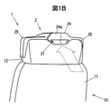
- FIGS. 1A and 1B are perspective views when the infection control device according to the embodiment of the present invention is attached to a seat.
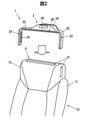
- FIG. 2 is an explanatory diagram illustrating the attachment of the air barrier forming unit to the seat in the infection control device of FIGS. 1A and 1B.
- FIG. 3 is a schematic diagram showing a configuration example of an air barrier forming unit in the infection control device of FIGS. 1A and 1B.
- the infection control device 1 is a device for suppressing airborne infection of a seated person seated in the seat 10.
- the seat 10 provided with the infection control device 1 is an aircraft seat (audience seat)
- the seat 10 provided with the infection control device 1 is not limited to the seat of an aircraft, and may be, for example, a seat of a long-distance train such as a Shinkansen or a limited express train, or a seat of a vehicle such as a bus, and is also applicable to a seat other than a vehicle. It is possible.
- the infection control device 1 can not only decompose and inactivate bacteria and viruses, but also suppress odors and remove particulate matter (PM), so that a large number of passengers can stay in a closed space for a long time. It can be used particularly favorably in vehicles that are forced to spend time in.
- PM particulate matter
- the seat 10 has a seat surface (not shown) and a backrest 11 extending upward from the rear end of the seat surface.
- a headrest 12 is provided on the upper part of the backrest 11.
- the seat 10 may have a reclining function capable of adjusting the inclination angle of the backrest 11 with respect to the seat surface.
- a plurality of seats 10 are arranged side by side in the cabin of an aircraft. More specifically, a plurality of seats 10 are arranged side by side in the front-rear direction and the left-right direction of the seat 10.
- the backrest 11 side of the seat 10 is the rear side, and the opposite side is the front side.
- the side of the seat 10 is in the left-right direction.
- the front-rear direction and the left-right direction with respect to the traveling direction of the vehicle coincide with the front-rear direction and the left-right direction of the seat 10, but the traveling direction of the vehicle and the seat 10 are not limited to this.
- the front-back direction and the left-right direction do not have to match.
- each of the front-back, left-right, and up-down directions shall represent the direction with respect to the seat 10.
- the infection control device 1 includes an air barrier forming unit 2.
- the air barrier forming unit 2 is provided for each seat 10.
- the air barrier forming unit 2 has an intake port 21 that takes in air from the rear, an air purifying mechanism 22 that purifies the air taken in from the intake port 21 to make clean air, and an outlet 23 that blows clean air forward. is doing. Details of the air barrier forming unit 2 will be described later.
- the air barrier forming unit 2 is configured to be removable from the seat 10. That is, the infection control device 1 includes a mounting portion 3 for detachably mounting the air barrier forming unit 2 to the seat 10.
- the mounting portion 3 is composed of the magic tape (registered trademark) 31.
- the velcro (registered trademark) 31 is attached to the upper surface and both side surfaces of the headrest 12 of the seat 10, and the contact surface with the headrest 12 in the air barrier forming unit 2 (the lower surface of the main body portion 24 described later, the arm portion 25 extending to the left and right). It is provided on the lower surface of the arm portion 25 and the side surface of the arm portion 25 extending vertically).
- the air barrier forming unit 2 is very lightweight because it uses a light emitting diode as the light source 223, and it is easy to use a simple mounting portion 3 such as the magic tape (registered trademark) 31. It can be fixed sufficiently.
- the specific configuration of the mounting portion 3 is not limited to this, and for example, the air barrier forming unit 2 may be fastened and fixed to the seat 10 by using bolts, or the air barrier may be fastened and fixed by using a band such as a nylon band or a rubber band.
- the forming unit 2 may be fixed to the seat 10 (for example, a portion of the headrest 12).
- a dedicated jig may be attached to the seat 10 and the air barrier forming unit 2 may be fixed to the jig.
- a jig may be fixed to the support of the headrest 12 and the air barrier forming unit 2 may be attached to the jig.
- the existing seat 10 can be used as it is, and the introduction cost can be significantly reduced as compared with the conventional technology of replacing each seat 10. Will be possible.
- the existing seat 10 can be used for seats 10 having various shapes, versatility is improved.
- the intake port 21 of the air barrier forming unit 2 is an opening provided in the back surface 24a of the main body portion 24 accommodating the air purifying mechanism 22, and is formed in a slit shape extending to the left and right in the present embodiment (FIG. 1B). reference).
- the main body portion 24 is placed on the headrest 12, extends to the left and right from the main body portion 24, and two arm portions 25 are formed so as to sandwich the headrest 12 from the left and right.
- the air barrier forming unit 2 is formed as a whole in a U shape rotated 90 degrees counterclockwise when viewed from the front, and is arranged so as to cover the upper side and the side of the headrest 12.
- the air outlet 23 is an opening formed at the front end portion of each of the two arm portions 25 (the front end portion of the arm portion 25 located on the side of the headrest 12), and is formed in a slit shape extending vertically.
- both outlets 23 are formed on the side of the headrest 12 so as to sandwich the headrest 12 from the left and right. Clean air is blown out from the outlet 23 so as to form a layer perpendicular to the left-right direction of the seat 10 (that is, parallel to the up-down and front-back directions) (broken line arrow in FIG. 1A). A).
- the air barrier forming unit 2 further has an upper air outlet 26 formed above the headrest 12 so as to face the front of the seat 10.
- the upper air outlet 26 is an opening formed in the front end portion of the arm portion 25 located above the main body portion 24 and the headrest 12, and is formed in a slit shape extending to the left and right. From the upper air outlet 26, clean air is blown out in a layer parallel to the left-right direction of the seat 10 toward the front. Here, clean air is blown out parallel to the seat surface (floor surface), and the clean air blown out from the upper outlet 26 is a layered shape perpendicular to the vertical direction (layered shape parallel to the left-right and front-back directions). ) (Dashed arrow B in FIG. 1A).
- the upper end portion of both outlets 23 and the side end portion of the upper outlet 26 are connected, and the two outlets 23 and the upper outlet 26 are integrated.
- the present invention is not limited to this, and the outlet 23 and the upper outlet 26 may be configured separately without connecting the outlet 23 and the upper outlet 26.
- the main body 24 is provided with an air purifying mechanism 22 and a fan 27.
- the air purifying mechanism 22 decomposes and inactivates bacteria and viruses, suppresses odors, and removes particulate matter from the air introduced from the intake port 21.
- the air purification mechanism 22 includes a photocatalyst-supported filter 221 in which a photocatalyst that exerts a photocatalyst function by irradiation with ultraviolet rays is carried and collects dust, a photocatalyst-supported filter 222 that collects dust that has passed through the photocatalyst-supported filter 221 and a photocatalyst. It has a light source 223 that irradiates the carrying filter 221 with ultraviolet rays.
- a first light emitting diode group 223a and a second light emitting diode group 223b in which light emitting diodes emitting ultraviolet light are arranged in a plane are used as the light source 223, a first light emitting diode group 223a and a second light emitting diode group 223b in which light emitting diodes emitting ultraviolet light are arranged in a plane are used. Further, a photocatalyst-supported filter 221 and a collection filter 222 are arranged between these two light emitting diode groups 223a and 223b. Further, in the present embodiment, a net-shaped (or sponge-shaped) pre-filter 224 is provided in the vicinity of the intake port 21.
- the air purification mechanism 22 sequentially arranges the pre-filter 224, the first light emitting diode group 223a, the photocatalyst-supporting filter 221, the collection filter 222, and the second light emitting diode group 223b in order from the intake port 21 side (right side in the figure). It is composed of.
- both light emitting diodes groups 223a and 223b having different emission wavelengths are used.
- the first light emitting diode group 223a uses a light emitting diode that emits deep ultraviolet light having a wavelength of 250 nm or more and 280 nm or less
- the second light emitting diode group 223b uses a light emitting diode that emits ultraviolet light having a wavelength of 360 nm or more and 380 nm or less.
- the first light emitting diode group 223a is mainly used for inactivating bacteria and viruses
- the second light emitting diode group 223b is mainly used for activating a photocatalyst.
- a photocatalyst containing apatite is supported on the first light emitting diode group 223a side, and a photocatalyst containing titanium oxide is supported on the second light emitting diode group 223b side. I used the one.
- a photocatalyst containing apatite which has a high ability to adsorb bacteria and viruses and has a high ability to inactivate, is provided on the side of the first light emitting diode group 223a, which is irradiated with deep ultraviolet light having a wavelength of 250 nm or more and 280 nm or less, which has a high bactericidal ability but a relatively weak intensity. By carrying it, the ability to inactivate bacteria and viruses can be further enhanced.
- the photocatalyst-supported filter 221 for example, one having a wall member that partitions a large number of spaces in a honeycomb shape and having a large number of photocatalyst particles enclosed in each space partitioned by the wall member can be used.
- the photocatalyst-supported filter 221 is, for example, a medium-high performance filter having a collection rate of 0.4 ⁇ m particles of less than 99%.
- the collection filter 222 for example, a quasi-HEPA filter (High Efficiency Particulate Air Filter) having a collection rate of 0.3 ⁇ m particles of 90% or more can be used.
- the collection filter 222 is not essential and can be omitted.
- the air purifying mechanism 22 having such a configuration, it is possible not only to decompose and inactivate bacteria and viruses, but also to suppress odors and remove particulate matter by removing odor-causing substances, which makes it comfortable for passengers. Can improve sex.
- NOx and the like can be decomposed, and fine particles such as PM2.5 can also be removed.
- light-shielding members that block ultraviolet light may be provided before and after the air purifying mechanism 22.
- the light-shielding member it is desirable to use a member that shields light but does not obstruct the passage of air. For example, a plurality of punching metals having a large number of holes are used, and the positions of the holes are shifted and stacked at predetermined intervals. It is possible to use the members and the like.
- the fan 27 is for sucking (intake) and discharging (blowing) air, and is provided downstream of the air cleaning mechanism 22 (on the side opposite to the intake port 21).
- the air introduced into the main body 24 from the intake port 21 by the fan 27 is purified by the air purifying mechanism 22 to become clean air, and is blown through the flow path in the main body 24 and the flow path in the arm 25. It will be blown out in layers from the outlet 23 and the upper outlet 26.
- the position where the fan 27 is provided is not limited to the one shown in the drawing, and may be provided near the outlet 23 or the upper outlet 26, for example, both in the vicinity of the outlet 23 and the upper outlet 26 and the main body portion 24.
- a fan may be provided in the. Further, as the fan 27, a vertical fan (line flow fan (registered trademark)) or a fan in which a plurality of small fans are arranged one above the other may be used.
- an air barrier that is, an air barrier (also referred to as an air curtain) can be formed on both sides and above the seat 10. It is possible to suppress the invasion of bacteria and viruses into the space partitioned by this air barrier, and to suppress airborne infection of the seated person in the seat 10.
- the air barrier forming unit 2 has a sensor 28 for detecting the state of the air taken in from the intake port 21 and a display 29 for displaying the state of the air detected by the sensor 28.
- a sensor 28 any one of a temperature sensor, a humidity sensor, an odor sensor, and a dust sensor, or a combination of one or more can be used.
- a sensor biosensor or the like capable of detecting a virus or a bacterium can be used as the sensor 28.
- the display 29 is provided so as to face forward on the front surface of the main body 24 (a portion above the upper outlet 26).
- the display 29 comprises, for example, a liquid crystal display, and displays the state of air taken in from the intake port 21.
- the display 29 of the small terminal can be used. It can also be configured to display the state of the air.
- the state of air detected by the sensor 28 can be configured to be output to an external device by wireless communication or the like.
- This makes it possible to analyze the distribution of air conditions (for example, temperature distribution, odor distribution, etc.) in the vehicle (inside the cabin, etc.) with an external device, for example, based on the analysis results, for example, new It will be possible to develop various aircraft and design aircraft air conditioning (air conditioning analysis). Further, by providing a display for displaying the analysis result in the cockpit or the like, it becomes possible to grasp the air state distribution even in the cockpit or the like.
- the air barrier forming unit 2 may have an air volume adjusting mechanism capable of adjusting the amount of clean air blown out from the outlet 23 and the upper outlet 26.
- the air volume adjusting mechanism is configured to be able to adjust the amount of clean air blown out by, for example, adjusting the rotation speed of the fan 27 by controlling the drive current of the fan 27 or by appropriately controlling the PWM control or the like.
- the air volume adjusting mechanism may be configured so that the amount of clean air blown out from the outlet 23 can be reduced to zero, that is, the blowing of clean air (formation of an air barrier) can be stopped.
- a controller that can be operated by the seated person may be provided on the armrest or the like of the seat 10, and the air barrier forming unit 2 (or each seat 10) may be individually adjusted by the operation of the controller. Further, it is not possible to adjust the air volume individually by the seated person, and the air volume of all the air barrier forming units 2 in the vehicle (inside the cabin) can be collectively managed.
- the external device may be configured to automatically adjust the air volume (blow-out amount) of each air barrier forming unit 2. For example, based on the analysis result of the distribution of the air state, it is possible to perform control such as increasing the air volume (blowing amount) of the air barrier forming unit 2 in the area where the detected value of the odor is large.
- the air barrier forming unit 2 is a blowout direction control mechanism that controls the blowout direction of clean air from the outlet 23 and the upper outlet 26 according to the reclining angle of the backrest 11 (the angle formed by the seat surface and the backrest 11). May have.
- the blowout direction control mechanism controls the angle of the fin 23a (see FIG. 3) provided at the blowout port 23 according to the reclining angle of the backrest 11, so that clean air is blown forward regardless of the reclining angle. Can be done.
- the blowout direction control mechanism is configured to be able to select whether the blowout direction of clean air from the outlet 23 or the upper outlet 26 is parallel to the seat surface (floor surface) or perpendicular to the backrest 11. May be done. If the clean air is blown out toward the floor, dust on the floor may fly up and adversely affect the surroundings. Therefore, the clean air should be blown out horizontally to the floor. It is preferable that the direction is higher than the horizontal direction.
- the arm portion 25 is configured to be expandable and contractible in the left-right direction so that the seats 10 having different sizes of the headrest 12 can be accommodated.
- the specific configuration of the mechanism for expanding and contracting the arm portion 25 is not particularly limited, but as shown in FIG. 4, for example, the portion extending to the left and right of the arm portion 25 is divided and the outer wall of the divided portion is divided.
- the arm portion 25 may be configured to be expandable and contractible by configuring the 25a and 25b so as to overlap each other and changing the overlapping width thereof. In the example of FIG.
- a protrusion 251 projecting outward is provided on the outer wall 25a of the arm portion 25 located inside at the overlapping portion, and the protrusion 251 is accommodated on the outer wall 25b of the arm portion 25 located outside at the overlapping portion.
- the mechanism of FIG. 4 is merely an example, and the specific configuration of the mechanism for expanding and contracting the arm portion 25 is not limited to the one shown in the figure.
- the power supply to the air purifying mechanism 22, the sensor 28, and the like may be performed by a built-in battery, or may be configured to supply power from the outside.
- the air barrier forming unit 2 may be connected to an external power source such as a vehicle power source.
- an external power source such as a vehicle power source.
- a general power cable used for AC or DC power supply may be used, or for example, power supply by a USB cable or power supply from a cigar socket is also possible.
- the air barrier forming unit 2 since the air barrier forming unit 2 is provided on the headrest 12, the outer walls of the main body portion 24 and the arm portion 25 are prevented so that the sound of the fan 27 and the sound of the air flow do not cause discomfort to the seated person. It is more preferable to construct the material with a material and structure having high soundproofing property.
- a sound absorbing structure using a sound absorbing material such as glass wool or urethane sponge, embossing, an uneven plate, or the like may be provided on at least a part of the outer wall of the main body portion 24 or the arm portion 25.
- the infection control device 1 is applied to the seat 10 for one person, but since the air barrier forming unit 2 in the present embodiment has a structure attached to the headrest 12, one person.
- This embodiment is applicable not only to the seat 10 for the seat 10 but also to the bench seat in which the headrest 12 is individually provided.
- the air barrier forming unit 2 is configured to be removable from the seat 10.
- the infection control device 1 can be introduced simply by attaching the air barrier forming unit 2 to the existing seat 10, and the introduction cost can be significantly reduced as compared with the conventional technology that requires replacement of each seat 10.
- the air barrier forming unit 2 can be applied to the seats 10 having various shapes, and the conventional technique in which the seat 10 and the air barrier forming unit 2 are integrally configured. It is possible to increase the versatility in comparison with.
- the infection control device 1 according to the present embodiment it is possible to control infection between passengers even in a narrow space such as a vehicle where it is difficult to secure a social distance.
- FIGS. 5A and 5B are perspective views when the infection control device 1a according to another embodiment of the present invention is attached to a seat.
- FIG. 6 is a schematic diagram showing a configuration example of the air barrier forming unit 2 in the infection control device 1a of FIGS. 5A and 5B.
- the main body portion 24 is provided on the back surface of the seat 10, and the arm portion 25 extending to the left and right from the main body portion 24 sandwiches the backrest 11 from the left and right. It is provided. Further, it has a head portion 241 extending upward from the main body portion 24 and facing forward above the headrest 12, and an upper outlet 26 is provided at the front end portion of the head portion 241.
- the clean air sent out by the fan 27 in the main body portion 24 is distributed to both arm portions 25 and the head portion 241 and blown out from both outlets 23 and the upper outlet 26.
- the main body 24 since the main body 24 is provided on the back surface of the seat 10, the discomfort of the seated person due to the sound and vibration of the fan 27 is further suppressed.
- the upper outlet 26 is not essential and can be omitted.
- the present invention has a seat other than a vehicle, for example, a seat in a movie theater or a theater, a seat in a waiting room of a hospital, or at the time of treatment. It can also be applied to the seats used.
- the infection control device (2) is provided with an air barrier forming unit (2) capable of blowing out the clean air in a vertical layer, and the air barrier forming unit (2) is detachably configured with respect to the seat (10). 1).
- the air barrier forming unit (2) has two arm portions (25) provided so as to sandwich the backrest (11) or the headrest (12) of the seat (10) from the left and right.
- the air barrier forming unit (2) is formed above the headrest (12) so as to face the front of the seat (10), and has a layered shape parallel to the left-right direction of the seat (10) in the front.
- the air barrier forming unit (2) has a sensor (28) for detecting the state of air taken in from the intake port (21) and the intake port (21) detected by the sensor (28).
- the infection control device (1) according to any one of [1] to [3], further comprising a display (29) for displaying the state of air taken in from the air.
Landscapes
- Engineering & Computer Science (AREA)
- Mechanical Engineering (AREA)
- Chemical & Material Sciences (AREA)
- Combustion & Propulsion (AREA)
- General Engineering & Computer Science (AREA)
- Health & Medical Sciences (AREA)
- Aviation & Aerospace Engineering (AREA)
- Animal Behavior & Ethology (AREA)
- Physics & Mathematics (AREA)
- Life Sciences & Earth Sciences (AREA)
- Transportation (AREA)
- General Health & Medical Sciences (AREA)
- Public Health (AREA)
- Veterinary Medicine (AREA)
- Epidemiology (AREA)
- Thermal Sciences (AREA)
- Chair Legs, Seat Parts, And Backrests (AREA)
- Seats For Vehicles (AREA)
- Air-Conditioning For Vehicles (AREA)
- Disinfection, Sterilisation Or Deodorisation Of Air (AREA)
- Fluid-Driven Valves (AREA)
Abstract
感染抑制装置1は、座席10に着席する着席者の空気感染を抑制するための装置であって、吸気口21、吸気口21から吸気した空気を清浄化して清浄空気とする空気清浄化機構22、及び、座席10の前方に清浄空気を吹き出す吹出口23を有し、吹出口23から座席10の左右方向に対して垂直な層状に清浄空気を吹き出し可能なエアバリア形成ユニット2を備え、エアバリア形成ユニット2は、座席10に対して着脱可能に構成されている。
Description
本発明は、例えば乗り物に搭載され、乗客間での感染を抑制するための感染抑制装置に関する。
航空機等の乗り物において、乗客間でのウィルスや細菌の感染が問題となっている。特許文献1では、座席のヘッドレストの側部から、座席に着席している乗客の顔の周囲へと清浄空気を供給する装置が提案されている。
特許文献1の装置は、座席と一体に設けられている。そのため、特許文献1の装置を導入するためには、座席全体を取り替える必要があった。そのため、既存の座席をそのまま利用することができずに導入コストが高くなってしまうおそれがあった。また、特許文献1の装置では、様々な形状の座席に対応することが困難であり、汎用性が低いという課題があった。
そこで、本発明は、汎用性が高く導入コストを抑制可能な感染抑制装置を提供することを目的とする。
本発明は、上記課題を解決することを目的として、座席に着席する着席者の空気感染を抑制するための感染抑制装置であって、吸気口、前記吸気口から吸気した空気を清浄化して清浄空気とする空気清浄化機構、及び、前記座席の前方に前記清浄空気を吹き出す吹出口を有し、前記吹出口から前記座席の左右方向に対して垂直な層状に前記清浄空気を吹き出し可能なエアバリア形成ユニットを備え、前記エアバリア形成ユニットは、前記座席に対して着脱可能に構成されている、感染抑制装置を提供する。
本発明によれば、汎用性が高く導入コストを抑制可能な感染抑制装置を提供できる。
[実施の形態]
以下、本発明の実施の形態を添付図面にしたがって説明する。
以下、本発明の実施の形態を添付図面にしたがって説明する。
図1A,図1Bは、本発明の一実施の形態に係る感染抑制装置を座席に取付けた際の斜視図である。図2は、図1A,図1Bの感染抑制装置におけるエアバリア形成ユニットの座席への取付けを説明する説明図である。図3は、図1A,図1Bの感染抑制装置におけるエアバリア形成ユニットの構成例を示す模式図である。
図1~3に示すように、感染抑制装置1は、座席10に着席する着席者の空気感染を抑制するための装置である。本実施の形態では、感染抑制装置1を設ける座席10が、航空機の座席(客席)である場合について説明する。ただし、感染抑制装置1を設ける座席10は航空機の座席に限らず、例えば、新幹線や特急電車等の長距離列車、あるいはバス等の乗り物の座席であってもよく、乗り物以外の座席にも適用可能である。詳細は後述するが、感染抑制装置1では、細菌やウィルスの分解及び不活化のみならず、臭いの抑制や粒子状物質(PM)の除去も可能であるため、多数の乗客が長時間閉鎖空間で過ごすことが強いられる乗り物において、特に好適に用いることができる。
座席10は、図示しない座面と、座面の後方の端部から上方に延びる背もたれ11と、を有している。背もたれ11の上部には、ヘッドレスト12が設けられている。座席10は、座面に対する背もたれ11の傾斜角度を調整可能なリクライニング機能を有していてもよい。
航空機のキャビンには、複数の座席10が整列して配置されている。より詳細には、座席10の前後方向及び左右方向に、複数の座席10が整列して配置されている。なお、ここでは、座席10の背もたれ11側を後方、その反対側を前方としている。また、座席10の側方を左右方向としている。一般的な航空機(旅客機)においては、乗り物の進行方向に対する前後方向、左右方向が、座席10の前後方向、左右方向と一致しているが、これに限らず、乗り物の進行方向と座席10の前後方向、左右方向が一致していなくてもよい。以下、前後、左右、上下の各方向は、座席10を基準とした方向を表すものとする。
感染抑制装置1は、エアバリア形成ユニット2を備えている。エアバリア形成ユニット2は、座席10毎に設けられる。エアバリア形成ユニット2は、後方から吸気する吸気口21と、吸気口21から吸気した空気を清浄化して清浄空気とする空気清浄化機構22と、前方に清浄空気を吹き出す吹出口23と、を有している。エアバリア形成ユニット2の詳細については、後述する。
本実施の形態に係る感染抑制装置1では、エアバリア形成ユニット2は、座席10に対して着脱可能に構成されている。すなわち、感染抑制装置1は、エアバリア形成ユニット2を、座席10に対して着脱可能に取付ける取付部3を備えている。
図3に示すように、本実施の形態では、取付部3が、マジックテープ(登録商標)31から構成されている。マジックテープ(登録商標)31は、座席10のヘッドレスト12の上面及び両側面に取付けられると共に、エアバリア形成ユニット2におけるヘッドレスト12との接触面(後述する本体部24の下面、左右に延びるアーム部25の下面、及び上下に延びるアーム部25の側面)に、それぞれ設けられている。詳細は後述するが、エアバリア形成ユニット2では、光源223として発光ダイオードを用いているために非常に軽量であり、マジックテープ(登録商標)31のような簡易な取付部3を用いても、容易にかつ十分に固定可能である。
なお、取付部3の具体的な構成はこれに限らず、例えば、ボルトを用いてエアバリア形成ユニット2を座席10に締結固定してもよいし、ナイロンバンドやゴムバンド等のバンドを用いてエアバリア形成ユニット2を座席10(例えばヘッドレスト12の部分)に固定してもよい。また、座席10に専用の治具を取付け、その治具にエアバリア形成ユニット2を固定するように構成してもよい。例えば、ヘッドレスト12の支柱に治具を固定し、その治具にエアバリア形成ユニット2を取付ける構成とすることもできる。また、座席10の枠等に係止するラッチ等の係止部をエアバリア形成ユニット2に設けておき、係止部を座席10に係止してエアバリア形成ユニット2を固定する構造等も可能である。
エアバリア形成ユニット2を、座席10に対して着脱可能とすることで、既存の座席10をそのまま利用することが可能になり、座席10ごと取り替える従来技術と比較して、導入コストを大幅に抑えることが可能になる。また、様々な形状の座席10に対応できるため、汎用性が向上する。
以下、エアバリア形成ユニット2について詳細に説明する。エアバリア形成ユニット2の吸気口21は、空気清浄化機構22を収容する本体部24の背面24aに設けられた開口であり、本実施の形態では左右に延びるスリット状に形成されている(図1B参照)。本実施の形態では、本体部24はヘッドレスト12の上に載置されており、本体部24から左右に延び、ヘッドレスト12を左右から挟み込むように2つのアーム部25が形成されている。エアバリア形成ユニット2は、全体として、前方から見て反時計回りに90度回転したコ字状に形成されており、ヘッドレスト12の上方と側方を覆うように配置されている。
吹出口23は、2つのアーム部25のそれぞれの前端部(ヘッドレスト12の側方に位置するアーム部25の前端部)に形成された開口であり、上下に延びるスリット状に形成されている。本実施の形態では、両吹出口23は、ヘッドレスト12を左右から挟み込むように、ヘッドレスト12の側方に形成されることになる。吹出口23からは、座席10の左右方向に対して垂直(すなわち、上下及び前後方向に対して平行)な層状となるように、清浄空気がそれぞれ吹出される(図1(a)の破線矢印A)。
また、エアバリア形成ユニット2は、ヘッドレスト12の上方に座席10の前方に臨むように形成された上側吹出口26をさらに有している。上側吹出口26は、本体部24及びヘッドレスト12の上方に位置するアーム部25の前端部に形成された開口であり、左右に延びるスリット状に形成されている。上側吹出口26からは、前方に向かって、座席10の左右方向に対して平行な層状に清浄空気が吹き出される。ここでは、座面(床面)に対して平行に清浄空気を吹き出しており、上側吹出口26から吹き出される清浄空気は、上下方向に対して垂直な層状(左右及び前後方向に平行な層状)とされる(図1Aの破線矢印B)。
本実施の形態では、両吹出口23の上端部と上側吹出口26の側端部が連結され、2つの吹出口23と上側吹出口26とが一体となっている。ただし、これに限らず、吹出口23と上側吹出口26とを連結せず、吹出口23と上側吹出口26とを別個に構成してもよい。上側吹出口26を有することで、座席10の上側からの空気の侵入が抑えられ、乗客等の飛沫感染をより抑制可能になる。なお、上側吹出口26は必須ではなく、省略可能である。
図3に示すように、本体部24には、空気清浄化機構22とファン27とが設けられている。空気清浄化機構22は、吸気口21から導入された空気に対して、細菌やウィルスの分解及び不活化を行い、かつ、臭いの抑制や粒子状物質の除去を行うものである。空気清浄化機構22は、紫外線の照射により光触媒機能を発揮する光触媒が担持され塵埃を捕集する光触媒担持フィルタ221と、光触媒担持フィルタ221を通過した塵埃を捕集する捕集フィルタ222と、光触媒担持フィルタ221に紫外線を照射する光源223と、を有している。
本実施の形態では、光源223として、紫外光を発する発光ダイオードを平面状に配置した第1発光ダイオード群223a及び第2発光ダイオード群223bを用いている。また、これら両発光ダイオード群223a,223bの間に光触媒担持フィルタ221と捕集フィルタ222を配置している。また、本実施の形態では、吸気口21の近傍に、また、ネット状(あるいはスポンジ状)のプレフィルタ224が設けられている。空気清浄化機構22は、吸気口21側(図示右側)から順に、プレフィルタ224、第1発光ダイオード群223a、光触媒担持フィルタ221、捕集フィルタ222、及び第2発光ダイオード群223bを順次配置して構成されている。
本実施の形態では、両発光ダイオード群223a,223bとして発光波長が異なるものを用いている。具体的には、第1発光ダイオード群223aでは、波長250nm以上280nm以下の深紫外光を発する発光ダイオードを用い、第2発光ダイオード群223bでは、波長360nm以上380nm以下の紫外光を発する発光ダイオードを用いた。第1発光ダイオード群223aは、主に細菌やウィルスの不活化のために用いられ、第2発光ダイオード群223bは、主に光触媒を活性化させるために用いられる。
さらに、本実施の形態では、光触媒担持フィルタ221として、第1発光ダイオード群223a側に、アパタイトを含有する光触媒が担持され、第2発光ダイオード群223b側に、酸化チタンを含む光触媒が担持されたものを用いた。殺菌能力が高いものの比較的強度の弱い波長250nm以上280nm以下の深紫外光が照射される第1発光ダイオード群223a側に、細菌やウィルスの吸着力及び不活化する能力が高いアパタイトを含む光触媒を担持させることで、細菌やウィルスを不活化させる能力をより高めることができる。
光触媒担持フィルタ221としては、例えば、ハニカム状に多数の空間を仕切る壁部材を有し、当該壁部材で仕切られた各空間内に多数の光触媒の粒子が封じ込められたものを用いることができる。光触媒担持フィルタ221は、例えば、0.4μmの粒子の捕集率が99%未満である中高性能フィルタとされる。
捕集フィルタ222としては、例えば、0.3μmの粒子の捕集率が90%以上の準HEPAフィルタ(High Efficiency Particulate Air Filter)を用いることができる。なお、捕集フィルタ222は必須ではなく、省略可能である。
このような構成の空気清浄化機構22を用いることで、細菌やウィルスの分解及び不活化のみならず、臭いの原因物質の除去による臭いの抑制や粒子状物質の除去も可能となり、乗客の快適性を向上できる。この空気清浄化機構22では、NOxなども分解可能であり、またPM2.5等の微粒子も除去可能である。
図示していないが、空気清浄化機構22の前後には、紫外光を遮断する遮光部材が設けられてもよい。遮光部材としては、光を遮蔽しつつも空気の通過を妨げないものを用いることが望ましく、例えば、多数の孔を有するパンチングメタルを複数枚用い、孔の位置をずらし所定の間隔をあけて重ねられた部材等を用いることができる。
ファン27は、空気の吸入(吸気)及び排出(吹き出し)を行うためのものであり、空気清浄化機構22の下流(吸気口21とは反対側)に設けられている。ファン27によって吸気口21から本体部24内に導入された空気は、空気清浄化機構22によって浄化され清浄空気となり、本体部24内の流路やアーム部25内の流路を通って、吹出口23や上側吹出口26から層状に吹き出されることになる。なお、ファン27を設ける位置は図示のものに限らず、例えば、吹出口23や上側吹出口26の近傍に設けてもよく、吹出口23や上側吹出口26の近傍と本体部24との両方にファンを設けてもよい。また、ファン27としては、縦型ファン(ラインフローファン(登録商標))や、複数の小型のファンを上下に並べて配置したものを用いてもよい。
吹出口23及び上側吹出口26から層状に空気を吹き出すことによって、座席10の両側及び上方にエアバリア、すなわち空気の障壁(エアカーテンとも呼称される)を形成することができる。このエアバリアによって区画された空間への細菌やウィルスの侵入を抑制し、座席10の着席者の空気感染を抑制することが可能になる。
また、エアバリア形成ユニット2に、吸気口21から吸気される空気の状態を検出するためのセンサ28と、センサ28が検出した空気の状態を表示する表示器29と、を有している。センサ28としては、温度センサ、湿度センサ、臭いセンサ、埃センサのいずれか、あるいは1つ以上を組み合わせて用いることができる。また、現在は実用化されていないが、将来的には、センサ28として、ウィルスや細菌を検出可能なセンサ(バイオセンサ等)を用いることもできる。
表示器29は、本体部24の前面(上側吹出口26よりも上側の部分)に前方に臨むように設けられている。表示器29は、例えば液晶ディスプレイからなり、吸気口21から吸気される空気の状態を表示する。これに限らず、エアバリア形成ユニット2と別体に表示器29を有する小型端末を備えるようにし、エアバリア形成ユニット2と小型端末との間で無線通信を行うことで、小型端末の表示器29に空気の状態を表示するように構成することもできる。小型端末を座席10のアームレスト等に配置することで、着席者は振り返ったり立ち上がったりすることなく、より容易に空気の状態を確認することが可能になる。
また、センサ28で検出した空気の状態は、無線通信等により外部装置に出力するように構成することもできる。これにより、例えば、外部装置にて、乗り物内(キャビン内など)の空気の状態の分布(例えば温度の分布、臭いの分布など)を解析することができ、分析結果を基に、例えば、新規な機体の開発や、航空機空調設計(空調解析)等を行うことが可能になる。また、分析結果を表示する表示器をコックピット等に設けることで、コックピット等でも、空気の状態分布を把握することが可能になる。
また、エアバリア形成ユニット2は、吹出口23や上側吹出口26からの清浄空気の吹出量を調整可能な風量調整機構を有していてもよい。風量調整機構は、例えば、ファン27の駆動電流の制御、あるいはPWM制御等の適宜な制御によってファン27の回転数を調整することにより、清浄空気の吹出量を調整可能に構成される。また、風量調整機構は、吹出口23からの清浄空気の吹出量をゼロにする、すなわち清浄空気の吹き出し(エアバリアの形成)を停止できるように構成されてもよい。
風量の調整については、座席10のアームレスト等に着席者が操作可能なコントローラを設け、当該コントローラの操作によってエアバリア形成ユニット2毎に(あるいは座席10毎に)個別に調整可能としてもよい。また、着席者による個別の風量の調整は不可とし、乗り物内(キャビン内)の全てのエアバリア形成ユニット2の風量を一括管理するように構成することもできる。上述のように外部装置にて空気の状態の分布を分析する場合、その外部装置により、それぞれのエアバリア形成ユニット2の風量(吹出量)を自動的に調整するように構成することもできる。例えば、空気の状態の分布の分析結果を基に、臭いの検出値が大きいエリアでエアバリア形成ユニット2の風量(吹出量)を大きくする等の制御を行うことができる。
さらに、エアバリア形成ユニット2は、背もたれ11のリクライニング角度(座面と背もたれ11とのなす角度)に応じて、吹出口23や上側吹出口26からの清浄空気の吹き出し方向を制御する吹き出し方向制御機構を有していてもよい。吹き出し方向制御機構は、吹出口23に設けられたフィン23a(図3参照)の角度を、背もたれ11のリクライニング角度に応じて制御することで、リクライニング角度によらず、前方に清浄空気を吹き出すことができる。また、吹き出し方向制御機構は、吹出口23や上側吹出口26からの清浄空気の吹き出し方向が、座面(床面)に対して平行か、あるいは背もたれ11に垂直な方向かを選択可能に構成されてもよい。なお、清浄空気の吹き出し方向が床面側に向いていると、床面の塵等が舞い上がり周囲に悪影響を及ぼすおそれがあるため、清浄空気の吹き出し方向は、床面に対して水平方向か、水平方向よりも上方の方向であるとよい。
図1~3では図示を省略しているが、ヘッドレスト12の大きさが異なる座席10にも対応できるように、アーム部25は左右方向に伸縮可能に構成されていることが望ましい。アーム部25を伸縮する機構の具体的な構成については特に限定されるものではないが、例えば図4に示すように、アーム部25のうち左右に延びる部分を分割すると共に、その分割部の外壁25a,25b同士を重ね合わせるように構成し、その重なり幅を変更することで、アーム部25を伸縮可能に構成してもよい。図4の例では、重なり部分で内側に位置するアーム部25の外壁25aに外方に突出する突起251を設けると共に、重なり部分で外側に位置するアーム部25の外壁25bに突起251を収容する複数の凹部252を左右方向に離間して設け、突起251を収容する凹部252を適宜選択することで、アーム部25の左右方向における伸縮幅を調整可能となっている。図4の例では、突起251をバネ等の付勢部材253により外方に付勢するよう構成することで、突起251を収容する凹部252の変更、すなわちアーム部25の伸縮幅の調整をより容易としている。ただし、図4の機構はあくまで一例であり、アーム部25を伸縮する機構の具体的な構成は図示のものに限定されない。
空気清浄化機構22やセンサ28等への電源供給は、内蔵されたバッテリにより行われてもよいし、外部から電源供給するように構成してもよい。外部から電源供給する場合、例えば、エアバリア形成ユニット2を乗り物の電源等の外部電源に接続するとよい。外部電源への接続形態としては、交流または直流の電源供給に用いる一般的な電源ケーブルを用いてもよいし、例えば、USBケーブルによる電源供給、シガーソケットからの電源供給も可能である。
さらに、本実施の形態では、ヘッドレスト12にエアバリア形成ユニット2を設けるため、ファン27の音や空気の流れによる音が着席者に不快感を与えないように、本体部24やアーム部25の外壁を防音性の高い材質や構造で構成することがより好ましい。例えば、本体部24やアーム部25の外壁の少なくとも一部に、グラスウールやウレタンスポンジなどの吸音材や、エンボスや凹凸板等を用いた吸音構造を設けてもよい。
本実施の形態では、感染抑制装置1を1人用の座席10に適用する場合について説明したが、本実施の形態におけるエアバリア形成ユニット2はヘッドレスト12に取付けられる構造となっているため、1人用の座席10に限らず、ヘッドレスト12が個別に設けられたベンチシートにも、本実施の形態は適用可能である。
(実施の形態の作用及び効果)
以上説明したように、本実施の形態に係る感染抑制装置1では、エアバリア形成ユニット2が、座席10に対して着脱可能に構成されている。これにより、既存の座席10にエアバリア形成ユニット2を取り付けるのみで感染抑制装置1を導入可能となり、座席10ごと取り替える必要がある従来技術と比較して、導入コストを大幅に削減することが可能になる。また、座席10と別体にエアバリア形成ユニット2を構成することにより、様々な形状の座席10にもエアバリア形成ユニット2を適用可能となり、座席10とエアバリア形成ユニット2とを一体に構成した従来技術と比較して、汎用性を高めることが可能である。本実施の形態に係る感染抑制装置1を用いることで、ソーシャルディスタンスを確保することが難しい乗り物等の狭い空間においても、乗客間の感染抑制が可能になる。
以上説明したように、本実施の形態に係る感染抑制装置1では、エアバリア形成ユニット2が、座席10に対して着脱可能に構成されている。これにより、既存の座席10にエアバリア形成ユニット2を取り付けるのみで感染抑制装置1を導入可能となり、座席10ごと取り替える必要がある従来技術と比較して、導入コストを大幅に削減することが可能になる。また、座席10と別体にエアバリア形成ユニット2を構成することにより、様々な形状の座席10にもエアバリア形成ユニット2を適用可能となり、座席10とエアバリア形成ユニット2とを一体に構成した従来技術と比較して、汎用性を高めることが可能である。本実施の形態に係る感染抑制装置1を用いることで、ソーシャルディスタンスを確保することが難しい乗り物等の狭い空間においても、乗客間の感染抑制が可能になる。
(他の実施の形態)
図5A,図5Bは、本発明の他の実施の形態に係る感染抑制装置1aを座席に取付けた際の斜視図である。図6は、図5A,図5Bの感染抑制装置1aにおけるエアバリア形成ユニット2の構成例を示す模式図である。
図5A,図5Bは、本発明の他の実施の形態に係る感染抑制装置1aを座席に取付けた際の斜視図である。図6は、図5A,図5Bの感染抑制装置1aにおけるエアバリア形成ユニット2の構成例を示す模式図である。
図5A,図5B、及び図6に示す感染抑制装置1aでは、本体部24が座席10の背面に設けられており、本体部24から左右に延びるアーム部25が背もたれ11を左右から挟み込むように設けられている。また、本体部24から上方に延び、ヘッドレスト12の上方で前方に臨むように設けられたヘッド部241を有しており、ヘッド部241の前端部に上側吹出口26が設けられている。本体部24でファン27により送り出された清浄空気は、両アーム部25とヘッド部241とに分配され、両吹出口23及び上側吹出口26から吹き出される。感染抑制装置1aでは、本体部24が座席10の背面に設けられるため、ファン27の音や振動による着席者の不快感がより抑制される。
(変形例)
上記実施の形態では、1つのエアバリア形成ユニット2が2つの吹出口23と上側吹出口26とを有する場合について説明したが、これに限らず、例えば、2つの吹出口23を有するエアバリア形成ユニットと、上側吹出口26を有するエアバリア形成ユニットとを別体に構成してもよい。また、吹出口23,26毎に別体にエアバリア形成ユニットを構成することもできる。つまり、複数のエアバリア形成ユニットを1つの座席10に取付けるようにしてもよい。
上記実施の形態では、1つのエアバリア形成ユニット2が2つの吹出口23と上側吹出口26とを有する場合について説明したが、これに限らず、例えば、2つの吹出口23を有するエアバリア形成ユニットと、上側吹出口26を有するエアバリア形成ユニットとを別体に構成してもよい。また、吹出口23,26毎に別体にエアバリア形成ユニットを構成することもできる。つまり、複数のエアバリア形成ユニットを1つの座席10に取付けるようにしてもよい。
また、上記実施の形態では、上側吹出口26を有する場合について説明したが、上側吹出口26は必須ではなく、省略可能である。
また、上記実施の形態では、座席10が飛行機の座席である場合について説明したが、本発明は、乗り物以外の座席、例えば、映画館や劇場等の座席、あるいは病院の待合室の座席や治療時に使用される座席等にも適用可能である。
(実施の形態のまとめ)
次に、以上説明した実施の形態から把握される技術思想について、実施の形態における符号等を援用して記載する。ただし、以下の記載における各符号等は、特許請求の範囲における構成要素を実施の形態に具体的に示した部材等に限定するものではない。
次に、以上説明した実施の形態から把握される技術思想について、実施の形態における符号等を援用して記載する。ただし、以下の記載における各符号等は、特許請求の範囲における構成要素を実施の形態に具体的に示した部材等に限定するものではない。
[1]座席(10)に着席する着席者の空気感染を抑制するための感染抑制装置(1)であって、吸気口(21)、前記吸気口(21)から吸気した空気を清浄化して清浄空気とする空気清浄化機構(22)、及び、前記座席(10)の前方に前記清浄空気を吹き出す吹出口(23)を有し、前記吹出口(23)から前記座席の左右方向に対して垂直な層状に前記清浄空気を吹き出し可能なエアバリア形成ユニット(2)を備え、前記エアバリア形成ユニット(2)は、前記座席(10)に対して着脱可能に構成されている、感染抑制装置(1)。
[2]前記エアバリア形成ユニット(2)は、前記座席(10)の背もたれ(11)又はヘッドレスト(12)を左右から挟み込むように設けられた2つのアーム部(25)を有し、前記2つのアーム部(25)のそれぞれの前端部に、前記吹出口(23)が形成されている、[1]に記載の感染抑制装置(1)。
[3]前記エアバリア形成ユニット(2)は、前記ヘッドレスト(12)の上方に前記座席(10)の前方に臨むように形成され、前方に前記座席(10)の左右方向に対して平行な層状に前記清浄空気を吹出す上側吹出口(26)をさらに有する、[2]に記載の感染抑制装置(1)。
[4]前記エアバリア形成ユニット(2)は、前記吸気口(21)から吸気される空気の状態を検出するためのセンサ(28)と、前記センサ(28)で検出した前記吸気口(21)から吸気される空気の状態を表示する表示器(29)と、をさらに有する、[1]乃至[3]の何れか1項に記載の感染抑制装置(1)。
以上、本発明の実施の形態を説明したが、上記に記載した実施の形態は特許請求の範囲に係る発明を限定するものではない。また、実施の形態の中で説明した特徴の組合せの全てが発明の課題を解決するための手段に必須であるとは限らない点に留意すべきである。また、本発明は、その趣旨を逸脱しない範囲で適宜変形して実施することが可能である。
1…感染抑制装置
2…エアバリア形成ユニット
21…吸気口
22…空気清浄化機構
23…吹出口
24…本体部
25…アーム部
26…上側吹出口
27…ファン
28…センサ
29…表示器
3…取付部
31…マジックテープ(登録商標)
10…座席
11…背もたれ
12…ヘッドレスト
2…エアバリア形成ユニット
21…吸気口
22…空気清浄化機構
23…吹出口
24…本体部
25…アーム部
26…上側吹出口
27…ファン
28…センサ
29…表示器
3…取付部
31…マジックテープ(登録商標)
10…座席
11…背もたれ
12…ヘッドレスト
Claims (4)
- 座席に着席する着席者の空気感染を抑制するための感染抑制装置であって、
吸気口、前記吸気口から吸気した空気を清浄化して清浄空気とする空気清浄化機構、及び、前記座席の前方に前記清浄空気を吹き出す吹出口を有し、前記吹出口から前記座席の左右方向に対して垂直な層状に前記清浄空気を吹き出し可能なエアバリア形成ユニットを備え、
前記エアバリア形成ユニットは、前記座席に対して着脱可能に構成されている、
感染抑制装置。 - 前記エアバリア形成ユニットは、前記座席の背もたれ又はヘッドレストを左右から挟み込むように設けられた2つのアーム部を有し、前記2つのアーム部のそれぞれの前端部に、前記吹出口が形成されている、
請求項1に記載の感染抑制装置。 - 前記エアバリア形成ユニットは、前記ヘッドレストの上方に前記座席の前方に臨むように形成され、前方に前記座席の左右方向に対して平行な層状に前記清浄空気を吹出す上側吹出口をさらに有する、
請求項2に記載の感染抑制装置。 - 前記エアバリア形成ユニットは、前記吸気口から吸気される空気の状態を検出するためのセンサと、前記センサで検出した前記吸気口から吸気される空気の状態を表示する表示器と、をさらに有する、
請求項1乃至3の何れか1項に記載の感染抑制装置。
Applications Claiming Priority (2)
| Application Number | Priority Date | Filing Date | Title |
|---|---|---|---|
| JP2020141535A JP7012795B1 (ja) | 2020-08-25 | 2020-08-25 | 感染抑制装置 |
| JP2020-141535 | 2020-08-25 |
Publications (1)
| Publication Number | Publication Date |
|---|---|
| WO2022044586A1 true WO2022044586A1 (ja) | 2022-03-03 |
Family
ID=80353179
Family Applications (1)
| Application Number | Title | Priority Date | Filing Date |
|---|---|---|---|
| PCT/JP2021/026316 Ceased WO2022044586A1 (ja) | 2020-08-25 | 2021-07-13 | 感染抑制装置 |
Country Status (3)
| Country | Link |
|---|---|
| JP (1) | JP7012795B1 (ja) |
| TW (1) | TWI778751B (ja) |
| WO (1) | WO2022044586A1 (ja) |
Cited By (5)
| Publication number | Priority date | Publication date | Assignee | Title |
|---|---|---|---|---|
| JP2023131802A (ja) * | 2022-03-10 | 2023-09-22 | テイ・エス テック株式会社 | 車両用通知システム |
| JP2023146468A (ja) * | 2022-03-29 | 2023-10-12 | 日機装株式会社 | 空気浄化装置 |
| CN117403504A (zh) * | 2022-07-14 | 2024-01-16 | 约瑟夫福格勒公司 | 用于筑路机的鼓风机装置 |
| JP2024079654A (ja) * | 2022-11-30 | 2024-06-11 | リア・コーポレーション | 空気偏向器 |
| EP4438810A1 (de) | 2023-03-27 | 2024-10-02 | Joseph Vögele AG | Strassenbaumaschine mit sitzkonsole zur frischluftversorgung sowie verfahren |
Families Citing this family (3)
| Publication number | Priority date | Publication date | Assignee | Title |
|---|---|---|---|---|
| JP2024002693A (ja) * | 2022-06-24 | 2024-01-11 | 株式会社竹中工務店 | 空調家具 |
| JP7845092B2 (ja) * | 2022-07-12 | 2026-04-14 | 株式会社デンソー | Pmセンサ |
| KR102864316B1 (ko) * | 2022-11-28 | 2025-09-25 | 주식회사 스마트름뱅이 | 공기정화모듈을 구비하는 차량용 헤드레스트 |
Citations (11)
| Publication number | Priority date | Publication date | Assignee | Title |
|---|---|---|---|---|
| US5160517A (en) * | 1990-11-21 | 1992-11-03 | Hicks Richard E | System for purifying air in a room |
| KR20150061828A (ko) * | 2013-11-28 | 2015-06-05 | 서울바이오시스 주식회사 | 살충 및 살균 기능을 포함하는 좌석 시스템 |
| JP2016112300A (ja) * | 2014-12-17 | 2016-06-23 | シャープ株式会社 | バックル及び車載用空気清浄機 |
| JP2016132353A (ja) * | 2015-01-20 | 2016-07-25 | パナソニックIpマネジメント株式会社 | 車載用空気清浄機およびそれを搭載した自動車 |
| JP2016203798A (ja) * | 2015-04-22 | 2016-12-08 | シャープ株式会社 | 固定具 |
| CN207617469U (zh) * | 2017-09-21 | 2018-07-17 | 格拉默车辆内饰(天津)有限公司 | 一种具有空气净化功能的驾驶员座椅 |
| KR20190093421A (ko) * | 2018-02-01 | 2019-08-09 | 한국과학기술원 | 미세먼지 정화와 환기가 동시에 가능한 공기청정기 |
| KR102089551B1 (ko) * | 2019-04-29 | 2020-03-16 | 코오롱글로텍주식회사 | 공기 청정기가 내장된 자동차용 헤드레스트 |
| KR102096443B1 (ko) * | 2019-10-14 | 2020-04-02 | 윤상근 | 버스용 실내 공기 정화 장치 |
| US20200114734A1 (en) * | 2018-10-12 | 2020-04-16 | Iqair Ag | Adapter plate for an air purifier for use in vehicles |
| WO2020137465A1 (ja) * | 2018-12-25 | 2020-07-02 | 日機装株式会社 | 感染抑制装置 |
Family Cites Families (5)
| Publication number | Priority date | Publication date | Assignee | Title |
|---|---|---|---|---|
| DE102004002074B3 (de) | 2004-01-15 | 2005-04-28 | Daimler Chrysler Ag | Fahrzeugsitz |
| JP2014141236A (ja) | 2012-12-27 | 2014-08-07 | Calsonic Kansei Corp | 車両用空気調和システム |
| CN204393889U (zh) * | 2014-10-29 | 2015-06-17 | 佛山市顺德区中兴汽车用品有限公司 | 一种无缝连接式空调坐垫 |
| JP7614483B2 (ja) | 2019-05-30 | 2025-01-16 | テイ・エス テック株式会社 | シート |
| CN111532292B (zh) | 2020-03-27 | 2022-02-15 | 中车工业研究院有限公司 | 基于疫情的客货两用轨道列车 |
-
2020
- 2020-08-25 JP JP2020141535A patent/JP7012795B1/ja active Active
-
2021
- 2021-07-13 WO PCT/JP2021/026316 patent/WO2022044586A1/ja not_active Ceased
- 2021-08-19 TW TW110130574A patent/TWI778751B/zh active
Patent Citations (11)
| Publication number | Priority date | Publication date | Assignee | Title |
|---|---|---|---|---|
| US5160517A (en) * | 1990-11-21 | 1992-11-03 | Hicks Richard E | System for purifying air in a room |
| KR20150061828A (ko) * | 2013-11-28 | 2015-06-05 | 서울바이오시스 주식회사 | 살충 및 살균 기능을 포함하는 좌석 시스템 |
| JP2016112300A (ja) * | 2014-12-17 | 2016-06-23 | シャープ株式会社 | バックル及び車載用空気清浄機 |
| JP2016132353A (ja) * | 2015-01-20 | 2016-07-25 | パナソニックIpマネジメント株式会社 | 車載用空気清浄機およびそれを搭載した自動車 |
| JP2016203798A (ja) * | 2015-04-22 | 2016-12-08 | シャープ株式会社 | 固定具 |
| CN207617469U (zh) * | 2017-09-21 | 2018-07-17 | 格拉默车辆内饰(天津)有限公司 | 一种具有空气净化功能的驾驶员座椅 |
| KR20190093421A (ko) * | 2018-02-01 | 2019-08-09 | 한국과학기술원 | 미세먼지 정화와 환기가 동시에 가능한 공기청정기 |
| US20200114734A1 (en) * | 2018-10-12 | 2020-04-16 | Iqair Ag | Adapter plate for an air purifier for use in vehicles |
| WO2020137465A1 (ja) * | 2018-12-25 | 2020-07-02 | 日機装株式会社 | 感染抑制装置 |
| KR102089551B1 (ko) * | 2019-04-29 | 2020-03-16 | 코오롱글로텍주식회사 | 공기 청정기가 내장된 자동차용 헤드레스트 |
| KR102096443B1 (ko) * | 2019-10-14 | 2020-04-02 | 윤상근 | 버스용 실내 공기 정화 장치 |
Cited By (7)
| Publication number | Priority date | Publication date | Assignee | Title |
|---|---|---|---|---|
| JP2023131802A (ja) * | 2022-03-10 | 2023-09-22 | テイ・エス テック株式会社 | 車両用通知システム |
| JP2023146468A (ja) * | 2022-03-29 | 2023-10-12 | 日機装株式会社 | 空気浄化装置 |
| JP7546009B2 (ja) | 2022-03-29 | 2024-09-05 | 日機装株式会社 | 空気浄化装置 |
| CN117403504A (zh) * | 2022-07-14 | 2024-01-16 | 约瑟夫福格勒公司 | 用于筑路机的鼓风机装置 |
| EP4306716A1 (de) * | 2022-07-14 | 2024-01-17 | Joseph Vögele AG | Gebläseeinrichtung für eine strassenbaumaschine |
| JP2024079654A (ja) * | 2022-11-30 | 2024-06-11 | リア・コーポレーション | 空気偏向器 |
| EP4438810A1 (de) | 2023-03-27 | 2024-10-02 | Joseph Vögele AG | Strassenbaumaschine mit sitzkonsole zur frischluftversorgung sowie verfahren |
Also Published As
| Publication number | Publication date |
|---|---|
| TW202208001A (zh) | 2022-03-01 |
| JP2022037412A (ja) | 2022-03-09 |
| JP7012795B1 (ja) | 2022-01-28 |
| TWI778751B (zh) | 2022-09-21 |
Similar Documents
| Publication | Publication Date | Title |
|---|---|---|
| JP7012795B1 (ja) | 感染抑制装置 | |
| JP6669845B1 (ja) | 感染抑制装置 | |
| JP4469390B2 (ja) | 車両用シート | |
| US11672882B1 (en) | Air treatment system for vehicles | |
| US11382993B2 (en) | Portable sanitizing systems and methods with range guidance | |
| KR101973536B1 (ko) | 광촉매 장치 | |
| JP7737243B2 (ja) | 空気清浄システム | |
| JP2026001150A (ja) | 乗物用シート | |
| US20220144038A1 (en) | Systems and methods useful for air treatment in a vehicle | |
| CN106553684A (zh) | 用于儿童的便携式可控环境系统 | |
| JP7755390B2 (ja) | 可搬型殺菌システムおよび方法 | |
| US20220265890A1 (en) | Fluid processing | |
| US20240399937A1 (en) | Vehicle seat | |
| EP2682320B1 (en) | Device for disinfecting the air in underground railway carriages | |
| CN110370896A (zh) | 一种车用空调回风装置、车用空调系统及车体 | |
| CN216091536U (zh) | 车辆消毒护罩 | |
| JP4192673B2 (ja) | 空気清浄機能を備えた車両用シート | |
| US20230088479A1 (en) | Vehicle with modular air treatment unit | |
| JP3028806B2 (ja) | 空気清浄装置 | |
| EP4112471B1 (en) | Ventilation assembly in an aircraft | |
| JP7653887B2 (ja) | 感染抑制装置 | |
| CN210760172U (zh) | 一种车用空调回风装置、车用空调系统及车体 | |
| CN116472190A (zh) | 用于交通工具舱室的消毒系统 | |
| KR102864316B1 (ko) | 공기정화모듈을 구비하는 차량용 헤드레스트 | |
| KR102591419B1 (ko) | 엘리베이터용 공기살균정화패널 및 이를 포함하는 엘리베이터 |
Legal Events
| Date | Code | Title | Description |
|---|---|---|---|
| 121 | Ep: the epo has been informed by wipo that ep was designated in this application |
Ref document number: 21861016 Country of ref document: EP Kind code of ref document: A1 |
|
| NENP | Non-entry into the national phase |
Ref country code: DE |
|
| 122 | Ep: pct application non-entry in european phase |
Ref document number: 21861016 Country of ref document: EP Kind code of ref document: A1 |