WO2022044576A1 - 樹脂成形品の弾性率の推定方法、樹脂成形品の応力推定方法、プログラム、コンピュータ可読記録媒体、樹脂成形品の弾性率の算定装置、樹脂成形品の製造方法、樹脂成形品の弾性率のデータ取得方法、樹脂成形品の形状最適化方法、樹脂成形品の変形予測方法、樹脂成形品の破壊寿命予測方法 - Google Patents
樹脂成形品の弾性率の推定方法、樹脂成形品の応力推定方法、プログラム、コンピュータ可読記録媒体、樹脂成形品の弾性率の算定装置、樹脂成形品の製造方法、樹脂成形品の弾性率のデータ取得方法、樹脂成形品の形状最適化方法、樹脂成形品の変形予測方法、樹脂成形品の破壊寿命予測方法 Download PDFInfo
- Publication number
- WO2022044576A1 WO2022044576A1 PCT/JP2021/026082 JP2021026082W WO2022044576A1 WO 2022044576 A1 WO2022044576 A1 WO 2022044576A1 JP 2021026082 W JP2021026082 W JP 2021026082W WO 2022044576 A1 WO2022044576 A1 WO 2022044576A1
- Authority
- WO
- WIPO (PCT)
- Prior art keywords
- resin molded
- molded product
- elastic modulus
- side plate
- molded article
- Prior art date
- Legal status (The legal status is an assumption and is not a legal conclusion. Google has not performed a legal analysis and makes no representation as to the accuracy of the status listed.)
- Ceased
Links
Images






Classifications
-
- B—PERFORMING OPERATIONS; TRANSPORTING
- B29—WORKING OF PLASTICS; WORKING OF SUBSTANCES IN A PLASTIC STATE IN GENERAL
- B29C—SHAPING OR JOINING OF PLASTICS; SHAPING OF MATERIAL IN A PLASTIC STATE, NOT OTHERWISE PROVIDED FOR; AFTER-TREATMENT OF THE SHAPED PRODUCTS, e.g. REPAIRING
- B29C45/00—Injection moulding, i.e. forcing the required volume of moulding material through a nozzle into a closed mould; Apparatus therefor
- B29C45/14—Injection moulding, i.e. forcing the required volume of moulding material through a nozzle into a closed mould; Apparatus therefor incorporating preformed parts or layers, e.g. injection moulding around inserts or for coating articles
-
- B—PERFORMING OPERATIONS; TRANSPORTING
- B29—WORKING OF PLASTICS; WORKING OF SUBSTANCES IN A PLASTIC STATE IN GENERAL
- B29C—SHAPING OR JOINING OF PLASTICS; SHAPING OF MATERIAL IN A PLASTIC STATE, NOT OTHERWISE PROVIDED FOR; AFTER-TREATMENT OF THE SHAPED PRODUCTS, e.g. REPAIRING
- B29C45/00—Injection moulding, i.e. forcing the required volume of moulding material through a nozzle into a closed mould; Apparatus therefor
- B29C45/17—Component parts, details or accessories; Auxiliary operations
- B29C45/76—Measuring, controlling or regulating
Definitions
- the present invention relates to a technique for calculating the elastic modulus of a resin molded product and a technique for calculating the internal stress of the resin molded product.
- Residual stress is generated inside the resin molded product in a series of processes for molding the resin, but if the residual stress is excessive, the resin molded product will warp, deform, or crack over time. Therefore, at the design stage of the resin molded product, the residual stress is estimated by using an analysis model (see, for example, JP-A-2006-205740 and JP-A-2012-152964).
- the elastic modulus (E) and strain of the resin molded product with respect to each temperature are required to derive the residual stress change based on the temperature change history of the resin molded product.
- ⁇ E ⁇ ⁇
- the actual elastic modulus (that is, relaxation elastic modulus) of the resin molded product in the process is conventional. It is considered that the elastic modulus is lower than the elastic modulus obtained by the three-point bending test or the like. Nevertheless, when the relationship between the temperature and elastic modulus acquired by a conventional method such as a three-point bending test is input to the analysis model, a higher residual stress value than the actual value is calculated. As a result, it is necessary to secure a large design margin of the resin molded product, which may lead to excessive quality.
- an object of the present invention is to accurately calculate the elastic modulus of the resin molded product in the process of removing it from the mold and then cooling it.
- the first aspect of the present invention is a process of removing from a mold and then cooling by using a theoretical formula when a bonded plate in which two plates having different thermal expansion coefficients are bonded is curved in response to a temperature change. It is a method of calculating the elasticity of a resin molded product, and is included in the first step of acquiring the relationship between the surface temperature and the shrinkage rate of the resin molded product in the process of taking it out from the mold and then cooling it, and the resin molded product.
- the secondary side plate In the second step of acquiring the measured values of the surface temperature and the warp amount of the joint plate, the shrinkage rate measured in the first step, the warp amount of the joint plate obtained in the second step, and the theoretical formula. Based on the third step of acquiring the relationship between the surface temperature and the elasticity of the secondary side plate, and the process of taking out from the mold and then cooling based on the relationship between the surface temperature and the elasticity of the secondary side plate. This is a method for calculating the elasticity of a resin molded product, which includes a fourth step of acquiring the relationship between the surface temperature of the resin molded product and the elasticity.
- a second aspect of the present invention is to obtain the resin molded product based on the relationship between the surface temperature of the resin molded product, the shrinkage rate and the elastic rate, which is obtained in the method for calculating the elasticity of the resin molded product.
- This is a stress calculation method for a resin molded product, which calculates the stress of the resin molded product in the process of taking it out of the mold and then cooling it.
- the third aspect of the present invention is to use a theoretical formula for joining two plates having different thermal expansion coefficients and bending the joint plate in response to a temperature change, and then cooling the joint plate after removing it from the mold. It is a program to execute a method of calculating the elasticity of the resin molded product in the process of performing, and the method acquires the relationship between the surface temperature of the resin molded product and the shrinkage rate in the process of taking out from the mold and then cooling.
- the first step joins a primary side plate containing a material having a thermal expansion coefficient different from the thermal expansion coefficient of the resin material contained in the resin molded product, and a secondary side plate containing the same resin material as the resin molded product.
- the fourth aspect of the present invention is a program for causing a computer to execute the stress calculation method for the resin molded product.
- the fifth aspect of the present invention is a computer-readable recording medium in which the program is recorded.
- a sixth aspect of the present invention is a process of removing from a mold and then cooling by using a theoretical formula when a bonded plate in which two plates having different thermal expansion coefficients are bonded is curved in response to a temperature change.
- a calculation device that calculates the elastic coefficient of a resin molded product, the first data acquisition unit that acquires the relationship between the surface temperature and shrinkage rate of the resin molded product in the process of taking it out of the mold and then cooling it, and the resin molding.
- the second data acquisition unit that acquires the measured values of the surface temperature of the next side plate and the amount of warpage of the joint plate, the shrinkage rate measured by the first data acquisition unit, and the joint plate acquired by the second data acquisition unit.
- a seventh aspect of the present invention determines at least one selected from the shape, material, and molding conditions of the resin molded product based on the internal stress calculated by the stress calculation method of the resin molded product. , A method for manufacturing a resin molded product, which manufactures a resin molded product based on the determination.
- the eighth aspect of the present invention is a process of removing from a mold and then cooling by using a theoretical formula when a bonded plate in which two plates having different thermal expansion coefficients are bonded is curved in response to a temperature change.
- the secondary side plate is formed in a joint plate in which a primary side plate containing a material having a thermal expansion coefficient different from the thermal expansion coefficient of the resin material contained in the above and a secondary side plate containing the same resin material as the resin molded product are joined.
- a method for acquiring elasticity data of a resin molded product which comprises a fourth step of acquiring data on the elasticity of the resin molded product by acquiring the relationship between the surface temperature of the resin molded product and the elasticity of the resin molded product. be.
- the ninth aspect of the present invention is the shape optimization of the resin molded product, which optimizes the shape of the resin molded product based on the internal stress of the resin molded product calculated by the stress calculation method of the resin molded product. The method.
- the tenth aspect of the present invention is a deformation prediction method for a resin molded product, which predicts deformation of the resin molded product based on the internal stress of the resin molded product calculated by the stress calculation method for the resin molded product. ..
- the eleventh aspect of the present invention is to predict the fracture life of the resin molded product based on the internal stress of the resin molded product calculated by the stress calculation method of the resin molded product. The method.
- the elastic modulus of the resin molded product in the process of being taken out from the mold and then cooled can be calculated with high accuracy.
- the resin material for molding the resin molded product to which the method for calculating the elastic modulus of the resin molded product according to the present invention is applied is not particularly limited, and a conventionally known resin material can be used. Further, a resin mixture obtained by blending a plurality of resin materials is also included in the above resin materials. Further, pigments such as nucleating agents, carbon black and inorganic fired pigments, antioxidants, stabilizers, plasticizers, lubricants, mold release agents and flame retardants are added to the resin to obtain desired properties.
- the applied resin material is also included.
- the shape of the resin molded product is not particularly limited, and the present invention can be applied to a resin molded product having any shape. In the present invention, the "elastic modulus of the resin molded product" means "the elastic modulus of the resin material for molding the resin molded product". The same applies to the relaxed modulus.
- Bimetal method The elastic modulus of a resin molded product obtained by the conventional method does not take into consideration the viscoelastic behavior (stress relaxation, etc.) in the process of cooling after being taken out from the mold, and the obtained elastic modulus is obtained.
- the principle of bimetal to the resin material, resin molding that fluctuates in the process of being taken out from the mold and then cooled.
- the elastic modulus of a product can be calculated accurately.
- Bimetal is a kind of composite metal material in which two metal plates having different coefficients of thermal expansion are joined, and has a property of being curved by a temperature change.
- the properties of bimetal are not limited to metal plates, and a bonded plate obtained by joining two plates of materials having different coefficients of thermal expansion has the same properties. Therefore, in the present embodiment, a primary side plate containing a material having a thermal expansion coefficient different from the thermal expansion coefficient of the resin material contained in the resin molded product for which the elastic modulus is calculated is included, and the same resin material as the resin molded product is included.
- the elastic modulus of the resin molded product is calculated using the joint plate to which the secondary side plate is joined.
- the method for calculating the elastic modulus of this resin molded product is referred to as "bimetal method" in the following description.
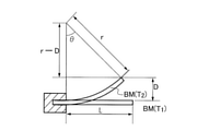
- FIG. 1 is a diagram illustrating the principle of the bimetal method.
- a state (BM (T 1 )) at a temperature T 1 which is an initial temperature before bending and a temperature T 2 after bending are shown.
- BM (T 2 ) in.
- the coefficients of thermal expansion of the primary side plate and the secondary side plate of the joint plate BM are set to ⁇ 1 and ⁇ 2 , respectively, and the elastic moduli (longitudinal elastic modulus) of the primary side plate and the secondary side plate of the joint plate BM are set to E 1 and E, respectively. Let it be 2 .
- the elastic modulus ratio m E 1 / E 2
- the plate thickness ratio n h 1 / h 2 .
- Equation (2) is geometrically established for the warp amount D of the joint plate BM (T 2 ) at the temperature T 2 after bending.
- L is the length of the joint plate BM (T 1 ) at the temperature T 1 .
- equation (1) and the equation (2) to the equation (3) are established.
- the elastic modulus of the resin molded product in the process of being taken out from the mold and then cooled is calculated by using the above theoretical formula (3). Therefore, a joint plate is prepared by joining a secondary side plate containing the same resin material as the resin molded product and a primary side plate containing a material having a thermal expansion coefficient different from that of the resin molded product.
- the primary side plate may be any material regardless of metal or resin as long as the coefficient of thermal expansion is different from that of the resin material of the resin molded product.
- the method of joining the primary side plate and the secondary side plate is not limited, but can be joined by injection molding. For example, insert molding in which the primary side plate is used as an insert member of a metal material or a resin material, or two-color molding in which both the primary side plate and the secondary side plate are made of a resin material can be used.
- the coefficient of thermal expansion ⁇ 2 of the secondary side plate is the molding shrinkage rate of the resin molded product ( Hereinafter, it is appropriately referred to simply as “shrinkage rate”).
- shrinkage rate the temperature dependence of the shrinkage rate of the secondary side plate, as will be described later, in the process of taking out the resin molded product from the mold and then cooling the resin molded product, the displacement amount of a predetermined portion on the surface of the resin molded product is sequentially measured. Obtained by that.
- the influence of the temperature distribution in the molded product is not taken into consideration. Normally, the influence of this temperature distribution is minor and can be ignored, but when considering this, the temperatures at the start of measurement of the material of the primary side plate and the resin material of the secondary side plate are set to T 1_start and T 2_start , respectively. Further, by using the following formula (4) in which the temperature at time t is expressed as T 1_t and T 2_t , instead of the above formula (1), the elastic modulus of the resin molded product can be obtained with higher accuracy. In particular, when the difference between the coefficient of thermal expansion ⁇ 1 of the material of the primary side plate and the coefficient of thermal expansion ⁇ 2 of the resin material of the secondary side plate is small, it is preferable to use this.
- the primary side plate is a resin material plate in a state that can be regarded as a solid.
- a crystalline resin material is used as the primary side plate, it is used in a state where crystallization is sufficiently advanced by performing an annealing treatment for a long time. Then, the temperature dependence of the physical properties of the primary side plate (elastic modulus E 1 , thermal expansion coefficient ⁇ 1 ) is acquired in advance.
- the method of acquiring the physical properties of the primary side plate at a predetermined temperature may be a standard method specified by JIS or ISO.
- the primary side plate When a metal material is used as the primary side plate, the temperature dependence of the physical properties (elastic modulus, coefficient of thermal expansion) of the metal material is extremely low, and no special pretreatment is required. Compared to this, the number of man-hours required for measurement preparation is small.
- the coefficient of thermal expansion of the resin material used for the secondary side plate is small, if a metal material having a similarly small thermal expansion coefficient and high rigidity is used for the primary side plate, the absolute value of the warp amount D of the joint plate becomes. Since it may become small and difficult to measure, it is preferable to use the primary side plate of the above-mentioned resin material so that this absolute value becomes large to some extent from the viewpoint of accurately measuring the warp amount D.
- the combination of the thermal expansion coefficients of the resin material for generating an appropriate warp amount D may be selected in consideration of the difference in the thermal expansion coefficients of the resin material of the primary side plate and the secondary side plate as described later.
- the coefficient of thermal expansion has anisotropy for both the material of the primary side plate (particularly when a resin material is used) and the resin material of the secondary side plate, the coefficient of thermal expansion in the flow direction during molding is achieved. Is used as the coefficient of thermal expansion in the present invention.
- the temperature T 1 is the temperature immediately after the resin molded product is taken out from the mold.
- the temperature T 2 is, for example, room temperature.
- the secondary containing the same resin material as the resin molded product By sequentially measuring the warp amount D of the joint plate when the temperature is changed from the temperature (same as the temperature) to the temperature T 2 (for example, room temperature), the secondary containing the same resin material as the resin molded product from the above formula (3).
- the temperature dependence of the elastic coefficient E 2 of the side plate can be calculated.
- the calculation may be performed by modifying the formula (3) based on the above formula (4).
- the temperature dependence of the elastic modulus E 2 of the secondary side plate based on the above theoretical formula may be calculated by substituting the value of each measurement result into each formula, but CAE is used. It may be done by analysis.
- CAE analysis software "ANSYS Mechanical" of ANSYS can analytically derive the warp amount D of the joint plate from the data of temperature and shape (including deformation), thermal expansion coefficient and elastic modulus. It is possible to calculate the elastic modulus E2 of the secondary side plate that matches the warp amount D of the joint plate actually measured by the bimetal method.
- the calculated elastic modulus of the secondary side plate can be used as the elastic modulus of the resin molded product.
- the warp amount D of the joint plate measured by the bimetal method is a value that reflects the relaxed elastic modulus of the resin material of the secondary side plate (that is, the resin material contained in the resin molded product for which the elastic modulus is calculated). .. That is, the elastic modulus of the secondary side plate is calculated by calculating the elastic modulus of the secondary side plate based on the measured warp amount D, and the calculated elastic modulus of the secondary side plate is the viscoelasticity in the process of cooling the resin molded product after it is taken out from the mold.
- the elastic behavior is taken into consideration. Therefore, the temperature dependence of the elastic modulus of the secondary side plate calculated as described above matches the temperature dependence of the elastic modulus in the process of cooling the resin molded product after it is taken out from the mold.
- FIG. 2 shows each step of the method for calculating elastic modulus of a resin molded product according to an embodiment. Hereinafter, each step will be described in order.
- the first step S1 in FIG. 2 is a step of acquiring the relationship between the surface temperature and the shrinkage rate of the resin molded product in the process of taking it out from the mold and then cooling it.
- the temperature dependence of the shrinkage rate of the resin molded product that is, the temperature dependence of the thermal expansion coefficient of the secondary side plate
- Data is required, and this data is acquired in the first step S1.
- the displacement amount of a predetermined portion on the surface of the resin molded product is measured while measuring the surface temperature of the resin molded product, and the predetermined portion is measured.
- the shrinkage rate of the resin molded product is calculated based on the measured value of the displacement amount of.
- the surface temperature of the resin molded product can be obtained by thermography.
- the portion to be measured (measurement target portion) of the displacement amount of the resin molded product can be arbitrarily defined.
- the measurement target portion may be, for example, an outer edge portion of the resin molded product.
- the difference between the vertical and / or horizontal length of the resin molded product immediately after being taken out from the mold and the value after cooling is used as the measurement target portion. It can be a displacement amount.
- the measurement target portion may be, for example, a portion including at least two lines parallel to the surface of the resin molded product. The change in the distance between the two lines can be used as the displacement amount of the measurement target portion. At least two wires may be formed by spraying onto a resin molded product immediately after being taken out from the mold.
- a portion including at least two lines molded in the resin molded product may be used as the measurement target portion.
- the distance between the two lines immediately after being taken out from the mold is X and the displacement amount is ⁇ x
- the shrinkage rate is expressed by ( ⁇ x / X) ⁇ 100 (%).
- images of the measurement target portion of the resin molded product are sequentially acquired by an imaging means such as a CCD camera, and the measurement target portion is based on the acquired image. Measure the amount of displacement.
- a pattern is formed on the surface of the resin molded product immediately after being taken out from the mold, a measurement target portion is specified from the pattern attached to the surface, and the displacement amount of the measurement target portion is measured.
- this measuring method since the local shrinkage rate of the surface of the resin molded product can be measured, the shrinkage rate distribution of the surface of the resin molded product can be obtained.
- this measurement method will be described with reference to FIGS. 3 to 6.
- the surface of a resin molded product with a pattern is divided into a plurality of regions, and the displacement amount between each region is measured from the deformation of the symbol in each region with one region as one symbol, and this displacement amount is used.
- the shrinkage rate of the resin molded product can be calculated. Since the shrinkage rate is calculated in each region, in this method, the distribution of the shrinkage rate of the resin molded product can be measured based on the displacement amount of each region after the resin molded product is taken out from the mold.
- the pattern attached to the surface of the resin molded product is not limited, and examples thereof include a speckled pattern, a streak pattern, a marble pattern, and a leather-like pattern.
- the pattern attached to the surface of the resin molded product may be one molded into the resin molded product (texture), or ink (for example, pigment ink) is sprayed by spraying immediately after being taken out from the mold (for example, within 5 seconds). It may be formed by doing.
- FIG. 3A shows an example in which the speckled pattern 11, which is an example of the pattern, is attached to the surface 1s of the resin molded product 1.
- FIG. 3B shows an example in which the surface 1s of the resin molded product 1 of FIG. 3A is divided into a plurality of regions R. Regions R1 to R4 in FIG. 3 (c) are enlarged views of a part of FIG. 3 (b).
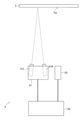
- FIG. 4 shows an exemplary arrangement of the data acquisition device 2 for acquiring the relationship between the surface temperature of the resin molded product 1 and the shrinkage rate.
- the data acquisition device 2 includes a stereo camera 21 including a pair of left side camera 21L and right side camera 21R, a thermography 23 (infrared sensor), and a control device 25.
- the left side camera 21L and the right side camera 21R of the stereo camera 21 sequentially acquire images of the surface 1s of the resin molded product 1 in the process of taking them out of the mold and then cooling them.
- thermography 23 measures the amount of infrared rays radiated from the surface 1s of the resin molded product 1 in synchronization with the imaging timing of the stereo camera 21, and acquires a temperature distribution image of the surface 1s.
- the control device 25 is connected to the stereo camera 21 and the thermography 23, and is configured to obtain the relationship between the temperature of each region set on the surface 1s of the resin molded product 1 and the shrinkage rate of the resin molded product 1.
- the above is just an example, and the configuration may be appropriately changed to have the same function.
- a single camera may be used instead of the stereo camera.
- the stereo camera 21 and the thermography 23 may be connected to different control devices instead of the same control device 25. In that case, the separately acquired surface temperature and shrinkage data may be integrated later so that the timings are synchronized, and the relationship between the surface temperature and the shrinkage of the resin molded product 1 may be acquired.
- FIG. 5 illustrates the difference between immediately after taking out the pattern from the mold and after cooling (that is, the difference before and after shrinkage) for the pattern included in a part of the plurality of regions included in the speckled pattern 11.
- the regions R1 to R4 immediately after being taken out from the mold are the same as those in FIG. 3 (c).
- the regions R1c to R4c indicate the contracted regions after the regions R1 to R4 immediately after being taken out from the mold are cooled.
- the measurement target portion (the portion defined by the distance D1) is specified from the symbols of the adjacent regions (for example, regions R2 and R4).
- the displacement amount is (D1-D2) and the contraction rate is ⁇ (D1-D2) / D1 ⁇ ⁇ 100 (%). be.
- the shrinkage rate distribution of the resin molded product 1 can be calculated.
- the measurement target site based on the symbol of the adjacent region is not limited to the example of FIG. 5, and can be arbitrarily defined.
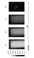
- the temperature distribution image of the surface 1s of the resin molded product 1 acquired by the thermography 23 is taken out from the mold and then cooled (in the order of (a) ⁇ (b) ⁇ (c) ⁇ (d)). ). Based on the temperature distribution image acquired by the thermography 23, it is possible to acquire the temperature in each region set on the surface 1s of the resin molded product 1 in the process of taking out from the mold and then cooling.
- the control device 25 controls so that the imaging timing of the stereo camera 21 and the measurement timing of the infrared amount of the thermography 23 are synchronized with each other.
- the control device 25 further measures the amount of displacement of each region with reference to a predetermined measurement target portion between adjacent regions immediately after being taken out from the mold, based on the images sequentially output from the stereo camera 21.
- the temperature of each region is acquired based on the temperature distribution image sequentially output from the thermography 23. From the above, according to the measurement method described with reference to FIGS. 3 to 6, the relationship between the surface temperature of the resin molded product 1 and the shrinkage rate in the process of taking out from the mold and then cooling is determined on the surface of the resin molded product 1. It can be acquired for each of the plurality of regions set in 1s (that is, the shrinkage rate distribution is acquired).
- the shrinkage ratio distribution of the resin molded product 1 It is not essential to obtain the shrinkage ratio distribution of the resin molded product 1. For example, if the shrinkage rate of the portion of interest on the surface of the resin molded product 1 can be obtained, the bimetal method can be applied to the portion.
- the second step S2 in FIG. 2 is a step of measuring the surface temperature of the secondary side plate of the joint plate and the amount of warpage of the joint plate. More specifically, the second step S2 includes a primary side plate containing a material having a thermal expansion coefficient different from the thermal expansion coefficient of the resin material contained in the resin molded product 1, and the same resin material as the resin molded product 1. A joint plate to which the secondary side plate and the secondary side plate are joined is manufactured by injection molding, and the measured values of the surface temperature of the secondary side plate and the amount of warpage of the joint plate are obtained in the manufactured joint plate.
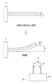
- FIG. 7 shows an exemplary arrangement of the data acquisition device 2 for acquiring the relationship between the surface temperature of the resin molded product 1 and the shrinkage rate.
- the manufactured joint plate 3 is formed by joining the primary side plate 31 and the secondary side plate 32.
- the primary side plate 31 is a primary side plate containing a material having a coefficient of thermal expansion different from the coefficient of thermal expansion of the resin material contained in the resin molded product 1.
- the secondary side plate 32 contains the same resin material as the resin molded product 1.
- the material of the primary side plate 31 may be any material as long as the difference in the coefficient of thermal expansion is different from the resin material of the secondary side plate 32, but if the difference in the coefficient of thermal expansion is too small, the amount of warpage of the joint plate to be measured is small.
- the elastic modulus of the secondary side plate 32 in the subsequent third step S3.
- the difference in the coefficient of thermal expansion is too large, the amount of warpage becomes large and it becomes necessary to consider the non-linearity of the material elasticity.
- the resin material used for the secondary side plate 32 contains a reinforcing inorganic filler such as glass fiber or carbon fiber (reinforced resin material)
- the amount of warpage is larger than that in the case where it is not mixed. descend.
- the coefficient of thermal expansion of the resin itself contained in the resin material used for the secondary side plate 32 is small.
- the difference in the coefficient of thermal expansion between the primary side plate 31 and the secondary side plate 32 is a resin material having a relatively large coefficient of thermal expansion as the secondary side plate 32 (a resin material that does not contain a reinforcing inorganic filler (non-reinforcing inorganic filler).
- a resin material having a coefficient of thermal expansion of 100 ⁇ 10 -6 [1 / K] or more, such as a reinforced resin material the range is within the range of 80 ⁇ 10 -6 to 170 ⁇ 10 -6 [1 / K].
- a resin material having a relatively small coefficient of thermal expansion such as a reinforced resin material, for example, a resin material having a coefficient of thermal expansion of 60 ⁇ 10 -6 [1 / K] or less
- a resin material having a relatively small coefficient of thermal expansion such as a reinforced resin material, for example, a resin material having a coefficient of thermal expansion of 60 ⁇ 10 -6 [1 / K] or less
- 15 ⁇ 10 -6 to 45 ⁇ 10 -6 [1 / K] is preferable.
- the method for manufacturing the joint plate 3 is not limited, but when the primary side plate 31 is used as a resin material, the resin material is insert-molded as an insert member, or the primary side plate 31 and the secondary side plate 32 are two-colored. Can be molded.
- the surface texture of the primary side plate 31 may be roughened in advance in order to improve the adhesion between the primary side plate 31 and the secondary side plate 32.
- the gate side of the injection molding apparatus is the fixed end of the joint plate 3, and the flow end side of the secondary side plate 32 is the free end.
- a material having a high affinity with the resin material of the secondary side plate 32 that is, the resin material contained in the resin molded product 1 is selected to improve the adhesion between the resin layers. It is preferable to increase it.
- the fixing tool 4 is not limited, but for example, a vise (vise) can be used as the fixing tool 4 to fix the joint plate 3.
- a vise vise
- a heat insulating plate is attached to the vise in advance, and the fixed end (end on the gate side) of the joint plate 3 immediately after being taken out from the mold is fixed with the vise via the heat insulating plate and cooled indoors.
- the camera 27 is arranged so as to acquire an image of the joint plate 3 from a direction orthogonal to a curved surface in which the joint plate 3 curves in response to a change in temperature.
- the thermography 28 measures the amount of infrared rays radiated from the surface of the secondary side plate 32 of the joint plate 3 in synchronization with the imaging timing of the camera 27, and acquires a temperature distribution image of the surface of the secondary side plate 32. Since it is sufficient that the surface temperature of the secondary side plate 32 can be obtained according to the passage of time, a thermocouple may be used instead of the thermography 28 or in addition to the thermography 23. In this case, the surface temperature of the secondary side plate 32 can be obtained by attaching a thermocouple to the surface of the secondary side plate 32 immediately after being taken out from the mold and sequentially receiving the output of the thermocouple by the control device 25. ..
- the control device 25 acquires the warp amount D of the joint plate 3 based on the images sequentially acquired from the camera 27, and acquires the temperature distribution image of the secondary side plate 32 of the joint plate 3 from the thermography 28.
- the temperature at the free end of the secondary side plate 32 in the temperature distribution image is evaluated, but when the secondary side plate 32 is molded from a reinforced resin material, the shrinkage rate is relatively small and the joint plate 3 is in the longitudinal direction.
- the temperature distribution may affect the amount of warpage. In such a case, it is preferable to consider the overall temperature distribution of the secondary side plate 32.
- the control device 25 determines the surface temperature of the secondary side plate 32 of the joint plate 3 and the warp of the joint plate 3. The relationship of the quantity D can be obtained.
- the shape of the joint plate 3, that is, the plate thickness, length, and width of the primary side plate 31 and the secondary side plate 32 can be appropriately determined by those skilled in the art so that a warp amount D within a desired range can be obtained. can. If the warp amount D is too small, it is difficult to accurately calculate the elastic modulus of the secondary side plate 32 in the subsequent third step S3. For example, when a reinforced resin material is used as the secondary side plate 32, it tends to be less likely to bend than a non-reinforced resin material. In that case, the length and the plate thickness can be adjusted with respect to the case of the non-reinforced resin material so as to be easily curved.
- the third step S3 in FIG. 2 is a step of acquiring the relationship between the surface temperature and the elastic modulus of the secondary side plate 32 of the joint plate 3. More specifically, in the third step S3, the shrinkage rate of the resin molded product 1 measured in the first step S1, the warp amount D of the joint plate 3 measured in the second step S2, and the above-mentioned bimetal method. Based on the formula (3), the relationship between the surface temperature of the secondary side plate 32 of the joint plate 3 and the elastic modulus is acquired.
- the relationship between the surface temperature of the resin molded product 1 and the shrinkage rate was obtained in the first step S1, but since the secondary side plate 32 of the joint plate 3 contains the resin material of the resin molded product 1, in the first step S1. , It is equivalent to acquiring the relationship between the surface temperature of the secondary side plate 32 and the thermal expansion coefficient ⁇ 2 .
- the second step S2 the relationship between the surface temperature of the secondary side plate 32 of the joint plate 3 and the warp amount D of the joint plate 3 has been acquired.
- the temperature dependence of the elastic modulus E 1 of the primary side plate 31 and the coefficient of thermal expansion ⁇ 1 has been measured in advance, and the plate thickness ratio n of the primary side plate 31 and the secondary side plate 32 and the length L of the joint plate are It is known.
- the fourth step S4 of FIG. 2 is a step of acquiring the relationship between the surface temperature and the elastic modulus of the resin molded product 1. More specifically, in the fourth step S4, based on the relationship between the surface temperature of the secondary side plate and the elastic modulus, the relationship between the surface temperature and the elastic modulus of the resin molded product 1 in the process of being taken out from the mold and then cooled is examined. get. In the third step S3, the relationship between the surface temperature of the secondary side plate 32 and the elastic modulus was acquired. However, since the resin molded product 1 contains the same resin material as the secondary side plate 32, the surface temperature and elastic modulus of the resin molded product 1 are obtained. The relationship between the rates can be the same as the relationship between the surface temperature of the secondary side plate 32 and the elastic modulus.
- a secondary side plate having the same resin material as the resin molded product is used.
- the joint plate is manufactured by injection molding using the method, and the elasticity of the secondary side plate, that is, the elasticity of the resin molded product is calculated based on the measured values of the surface temperature of the secondary side plate and the amount of warpage of the joint plate.
- the measured value of the warp amount of the joint plate reflects the influence of viscoelasticity (stress relaxation, etc.) in the process of solidification of the secondary side plate, the above formula is based on this measured value.
- the elastic modulus calculated from (3) is close to the measured value.
- the method for acquiring data on elastic modulus of resin molded product according to one embodiment is to execute the above steps S1 to S4 to obtain data on elastic modulus of resin molded product 1. Is a way to get.
- the stress calculation method for the resin molded product according to the embodiment is the relationship between the surface temperature and the shrinkage rate of the resin molded product acquired in the first step S1 of the above-mentioned method for calculating the elasticity.
- the calculated elastic modulus is a value close to the actual measurement, so that the internal stress of the resin molded product calculated based on the elastic modulus has high accuracy. It becomes a thing.
- FIG. 8 shows a data acquisition device 2 (a device for calculating the elastic modulus of the resin molded product) for executing the above-mentioned method for calculating the elastic modulus of the resin molded product. It is a block diagram which shows the hardware configuration of 1).
- the control device 25 of the data acquisition device 2 includes a CPU (Central Processing Unit) 251, a ROM (Read-only Memory) 252, a RAM (Random Access Memory) 253, a storage 254, and input / output (input / output). I / O) Interface 255 is provided.
- a CPU Central Processing Unit
- ROM Read-only Memory
- RAM Random Access Memory
- the input / output interface 255 is connected to the stereo camera 21, the camera 27, and the thermography 23, 28, for example, by wire.
- An elastic modulus calculation program, a stress calculation program, and the like are recorded in the ROM 252.
- the CPU 251 expands the program recorded in the ROM 252 into the RAM 253 and executes it as needed.
- the CPU 251 By executing the elasticity calculation program, the CPU 251 sends a data acquisition command to the stereo camera 21 and the thermography 23 at the same timing in the first step S1, and acquires image data from the stereo camera 21.
- the data of the temperature distribution image of the resin molded product 1 is acquired from the thermography 23.
- the CPU 251 sends a data acquisition command to the camera 27 and the thermography 28 at the same timing in the second step S2 by executing the elasticity calculation program, and acquires an image of the joint plate 3 from the camera 27. Then, the data of the temperature distribution image of the surface of the secondary side plate 32 of the joining plate 3 is acquired from the thermography 28.
- the elastic modulus calculation program includes a contraction rate acquisition module 401, a warp amount acquisition module 402, and an elastic modulus acquisition module 403, 404.
- the shrinkage rate acquisition module 401 determines the surface temperature and shrinkage rate of the resin molded product 1 in the process of being taken out from the mold and then cooled based on the data acquired in the first step S1 from the stereo camera 21 and the thermography 23.
- the warp amount acquisition module 402 obtains the measured values of the surface temperature of the secondary side plate 32 of the joint plate 3 and the warp amount of the joint plate 3 based on the data acquired in the second step S2 from the camera 27 and the thermography 28. It is a program module to be acquired.
- the elastic modulus acquisition module 403 is based on the shrinkage rate of the resin molded product 1 acquired by the shrinkage coefficient acquisition module 401, the warp amount of the joint plate 3 acquired by the warp amount acquisition module 402, and the formula (3) of the bimetal method. Based on this, it is a program module that acquires the relationship between the surface temperature of the secondary side plate 32 and the elastic modulus.
- the elastic modulus acquisition module 404 is a resin molded product in the process of being taken out from the mold and then cooled based on the relationship between the surface temperature of the secondary side plate 32 of the joint plate 3 and the elastic modulus acquired by the elastic modulus acquisition module 403. It is a program module for acquiring the relationship between the surface temperature and the elastic modulus of 1.
- the relationship between the surface temperature of the resin molded product 1 and the elastic modulus is the surface temperature and elasticity of the secondary side plate 32 of the joint plate 3. It can be the same as the relationship of rates.
- the stress calculation program may be any program as long as it calculates the internal stress of the resin molded product 1.
- the CPU 251 executes the stress calculation program, the relationship between the surface temperature and the shrinkage of the resin molded product 1 acquired by the shrinkage acquisition module 401 of the elastic modulus calculation program, and the elastic modulus acquisition module 404 of the elastic modulus calculation program.
- the internal stress of the resin molded product 1 can be calculated based on the relationship between the surface temperature of the resin molded product 1 and the elastic modulus obtained in 1.
- the elastic modulus calculation program and / or the stress calculation program may be recorded on a computer-readable recording medium.
- the manufacturing method of the resin molded product is based on the internal stress calculated by the stress calculation method of the resin molded product, and the shape, material, and the shape of the resin molded product. It is a method of determining at least one selected from molding conditions and manufacturing a resin molded product based on the determination. That is, by combining the internal stress of the resin molded product calculated by the stress calculation method of the resin molded product and the flow analysis, the shape of the resin molded product and / or the temperature of the molding die can be determined.
- the method for optimizing the shape of the resin molded product according to one embodiment is based on the internal stress of the resin molded product calculated by the above-mentioned stress calculation method for the resin molded product. This is a method for optimizing the shape of a resin molded product.
- the internal stress of the resin molded product can be obtained by the stress calculation method for the resin molded product. The distribution can be obtained. Therefore, for example, the shape of the resin molded product can be optimized so that the internal stress does not increase locally.
- the stress calculation step of calculating the internal stress of the resin molded product by the stress calculation method of the resin molded product and the internal stress calculated by the stress calculation step are predetermined.
- Calculated by a stress calculation process including a site specifying step for specifying a site of a resin molded product higher than the threshold and a shape changing step for changing the shape of the resin molded product including the site specified by the site specifying step.
- the stress calculation step, the site identification step, and the shape changing step may be repeated until the internal stress becomes equal to or less than the threshold value.
- the deformation prediction method of the resin molded product is based on the internal stress of the resin molded product calculated by the stress calculation method of the resin molded product. It is a method of predicting the deformation of.
- the stress calculation method for the resin molded product the internal stress of the resin molded product can be calculated with high accuracy. Therefore, if this internal stress is used, the deformation of the resin molded product can be predicted with high accuracy.
- CAE Computer-aided Engineering
- the fracture life prediction method for a resin molded product is based on the internal stress of the resin molded product calculated by the stress calculation method for the resin molded product. This is a method for predicting the fracture life of a molded product. Since the stress calculation method for the resin molded product can calculate the internal stress of the resin molded product with high accuracy, the fracture life of the resin molded product can be predicted with high accuracy by using this internal stress. It is preferable to use computer-aided analysis for predicting the fracture life of the resin molded product, and for example, CAE analysis can be used.
- a plate-shaped resin molded product (plate thickness 3.2 mm, length 130.0 mm, plate width 13.0 mm) was produced by an injection molding method. Molding was performed with a mold temperature of 140 ° C. and a holding pressure of 80 MPa.
- the resin material used is polyacetal resin (Duracon (registered trademark) M270-44 (manufactured by Polyplastics)).
- the pigment ink was sprayed on the resin molded product to give an irregular spot pattern on the surface of the resin molded product.
- the part on the flow end side of the resin molded product was set as the measurement target part, and a digital 3D-correlation system VIC-3D (manufactured by Correlated Solutions) was used. The amount of displacement of the measurement target site was measured, and the shrinkage rate was derived.
- the relationship between the temperature of the resin molded product and the shrinkage rate was obtained by acquiring the temperature of the measurement target part in the process of taking it out from the mold and then cooling it by thermography. The results are shown in FIG. As shown in FIG.
- the molding shrinkage rate of the resin molded product increases in the process of cooling from the temperature (108 ° C.) immediately after the resin molded product is taken out from the mold to room temperature (23 ° C.), and the resin molded product shrinks at 23 ° C. The rate was 1.7%.
- -Primary side plate Aluminum alloy (A5052P) (plate thickness 3.0 mm, length 130.0 mm, plate width 13.0 mm)
- -Secondary side plate Resin molded product (plate thickness 3.2 mm, length) of the same resin material (polyacetal resin (Duracon (registered trademark) M270-44 (manufactured by Polyplastics))) as that used in the first step.
- the surface is based on the relationship between the surface temperature of the resin molded product (same as the secondary side plate in the second step) and the amount of warpage of the joint plate, and the relationship between the surface temperature of the resin molded product obtained in the first step and the shrinkage rate.
- the calculated elastic modulus for each temperature is shown in "Elastic modulus (Example)" of FIG.
- FIG. 10 the relationship between the temperature and the shrinkage rate shown in FIG. 9 is also described.
- the “elastic modulus (comparative example)” in FIG. 10 indicates the elastic modulus obtained by the method conventionally used for the plate-shaped resin molded product. That is, the elastic modulus (comparative example) is obtained by carrying out a three-point bending test according to ISO178 and JIS K7171 at different temperatures to obtain the relationship between the temperature and the elastic modulus of the plate-shaped resin molded product. .. As shown in FIG. 10, it can be seen that the elastic modulus (Example) is lower than the elastic modulus (Comparative Example) in all temperature ranges. This is because the elastic modulus (Example) takes into consideration stress relaxation associated with the viscoelastic behavior of the resin molded product in the process of taking it out from the mold and then cooling it.
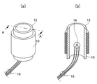
- FIG. 11 (b) is a cross-sectional view taken along the line AA'in FIG. 11 (a).
- the insert molded product includes a resin member 10 and a cylindrical insert member 12 to which a strain gauge 14 is attached at a position (inner wall) that does not come into contact with the resin member 10.
- the strain gauge 14 was connected to a strain measuring instrument (not shown) using a cable 16.
- the insert-molded product uses the same polyacetal resin used in the first and second steps as the resin member, and the insert member is a flat-walled hollow cylinder made of Ti-6Al-4V (cylinder outer diameter 25 mm, cylinder).
- a resin member (outer diameter 35 mm, inner diameter 25 mm, height 30 mm) was insert-molded on the outer periphery of the insert member using a portion inner diameter 21 mm, height 45 mm).
- KFU-2-120-D17-11 manufactured by Kyowa Electric Co., Ltd. was used as the strain gauge attached to the insert molded product.
- the mold temperature was set to 80 ° C. and the holding pressure was set to 80 MPa.
- the holding pressure time was set to 20 seconds, and the cooling time in the mold was set to 20 seconds.
- the inner wall temperature and internal stress (circumferential stress) of the insert member 12 in the process of taking out the insert molded product from the mold and then cooling it were measured.
- the strain value (initial value A) of the inner wall of the insert member in the state where the resin member is not molded is measured in advance by the strain gauge attached to the inner wall of the insert member, and the strain is measured by the strain gauge.
- the resin member was insert-molded on the outer periphery of the insert member, and the strain value (B) of the inner wall of the insert member in the process of taking out the insert-molded product from the mold and then cooling the insert member was continuously measured.
- the internal stress (circumferential stress) of the resin member 10 in the insert molded product is used by using the strain generated on the inner wall of the insert member 12 obtained by calculating the strain change value (BA) from this and the initial value A. ) was calculated.
- the temperature of the insert member 12 in the process of taking out from the mold and then cooling was measured.
- the temperature of the insert member 12 that is, the surface temperature of the resin member 10 in contact with the temperature
- Data showing the relationship of internal stress (circumferential stress) was acquired and used as the measured value.
- the internal stress (actual measurement 1 to 3) of the resin member 10 after cooling was 15.3 MPa.
- FIG. 12 shows the relationship between the surface temperature and the internal stress derived by inputting the relationship between the surface temperature and the shrinkage rate and the relationship between the surface temperature and the elastic modulus (comparative example) shown in FIG. 10 in the same structural analysis model. Is shown as "analysis (comparative example)".
- analysis comparative example
- the present invention relates to the patent application of Japanese Patent Application No. 2020-141575 filed with the Japan Patent Office on August 25, 2020, and the entire contents of this application are incorporated herein by reference.
Landscapes
- Engineering & Computer Science (AREA)
- Manufacturing & Machinery (AREA)
- Mechanical Engineering (AREA)
- Injection Moulding Of Plastics Or The Like (AREA)
Abstract
本発明の一実施形態は、金型から取り出してから冷却する過程の前記樹脂成形品の表面温度と収縮率の関係を取得する第1工程と、樹脂成形品に含まれる樹脂材料の熱膨張係数とは異なる熱膨張係数の材料を含む一次側板と、樹脂成形品と同一の樹脂材料を含む二次側板と、を接合させた接合板において、二次側板の表面温度と接合板の反り量の測定値を取得する第2工程と、第1工程において測定された収縮率、第2工程において取得された接合板の反り量、及び、理論式に基づいて、二次側板の表面温度と弾性率の関係を取得する第3工程と、二次側板の表面温度と弾性率の関係に基づいて、金型から取り出してから冷却する過程の樹脂成形品の表面温度と弾性率の関係を取得する第4工程と、を含む、樹脂成形品の弾性率の算定方法である。
Description
本発明は、樹脂成形品の弾性率を算定する技術、及び、樹脂成形品の内部応力を算出する技術に関する。
樹脂を成形する一連のプロセスで樹脂成形品の内部に残留応力が発生するが、残留応力が過大である場合、時間の経過によって樹脂成形品に反りや変形、クラックが発生する。そこで、樹脂成形品の設計段階で、解析モデルを用いて残留応力を推定することが行われている(例えば、特開2006-205740号公報,特開2012-152964号公報を参照)。
解析モデルを用いて樹脂成形品の残留応力を推定する場合、樹脂成形品の温度変化履歴に基づく残留応力変化を導出するためには、各温度に対する樹脂成形品の弾性率(E)と歪み(ε)に基づいて残留応力(σ)を逐次的に算出する(σ=E×ε)。
ここで、従来は、例えばISO178及びJIS K7171に沿った3点曲げ試験などによる弾性率の測定を異なる温度で実施することにより、樹脂成形品の温度と弾性率の関係を取得し、解析モデルに入力していた。
ここで、従来は、例えばISO178及びJIS K7171に沿った3点曲げ試験などによる弾性率の測定を異なる温度で実施することにより、樹脂成形品の温度と弾性率の関係を取得し、解析モデルに入力していた。
しかし、金型から取り出してから冷却する過程での樹脂には応力緩和等の粘弾性の挙動があることから、当該過程における実際の樹脂成形品の弾性率(つまり、緩和弾性率)は、従来の3点曲げ試験などにより取得される弾性率よりも低い値になると考えられる。それにも関わらず、3点曲げ試験などの従来の手法で取得された温度と弾性率の関係を解析モデルに入力すると、実際よりも高い残留応力の値が算出されてしまう。結果として、樹脂成形品の設計余裕度を大きく確保する必要があり、過剰品質を招来する虞がある。
そこで、本発明は、金型から取り出してから冷却する過程の樹脂成形品の弾性率を精度良く算定することを目的とする。
本発明の第1の観点は、熱膨張係数が異なる2枚の板を接合させた接合板が温度変化に応じて湾曲するときの理論式を用いて、金型から取り出してから冷却する過程の樹脂成形品の弾性率を算定する方法であって、金型から取り出してから冷却する過程の前記樹脂成形品の表面温度と収縮率の関係を取得する第1工程と、前記樹脂成形品に含まれる樹脂材料の熱膨張係数とは異なる熱膨張係数の材料を含む一次側板と、前記樹脂成形品と同一の樹脂材料を含む二次側板と、を接合させた接合板において、前記二次側板の表面温度と前記接合板の反り量の測定値を取得する第2工程と、第1工程において測定された収縮率、第2工程において取得された前記接合板の反り量、及び、前記理論式に基づいて、前記二次側板の表面温度と弾性率の関係を取得する第3工程と、前記二次側板の表面温度と弾性率の関係に基づいて、金型から取り出してから冷却する過程の前記樹脂成形品の表面温度と弾性率の関係を取得する第4工程と、を含む、樹脂成形品の弾性率の算定方法である。
本発明の第2の観点は、前記樹脂成形品の弾性率の算定方法において取得された、前記樹脂成形品の表面温度と、収縮率及び弾性率との関係に基づいて、前記樹脂成形品を金型から取り出してから冷却する過程の前記樹脂成形品の応力を算出する、樹脂成形品の応力算出方法である。
本発明の第3の観点は、熱膨張係数が異なる2枚の板を接合させた接合板が温度変化に応じて湾曲するときの理論式を用いて、コンピュータに、金型から取り出してから冷却する過程の樹脂成形品の弾性率を算定する方法を実行させるプログラムであって、前記方法は、金型から取り出してから冷却する過程の前記樹脂成形品の表面温度と収縮率の関係を取得する第1工程と、前記樹脂成形品に含まれる樹脂材料の熱膨張係数とは異なる熱膨張係数の材料を含む一次側板と、前記樹脂成形品と同一の樹脂材料を含む二次側板と、を接合させた接合板において、前記二次側板の表面温度と前記接合板の反り量の測定値を取得する第2工程と、第1工程において測定された前記収縮率、第2工程において取得された前記接合板の反り量、及び、前記理論式に基づいて、前記二次側板の表面温度と弾性率の関係を取得する第3工程と、前記二次側板の表面温度と弾性率の関係に基づいて、金型から取り出してから冷却する過程の前記樹脂成形品の表面温度と弾性率の関係を取得する第4工程と、を含む、プログラムである。
本発明の第4の観点は、コンピュータに、前記樹脂成形品の応力算出方法を実行させるプログラムである。
本発明の第5の観点は、前記プログラムが記録されたコンピュータ可読記録媒体である。
本発明の第6の観点は、熱膨張係数が異なる2枚の板を接合させた接合板が温度変化に応じて湾曲するときの理論式を用いて、金型から取り出してから冷却する過程の樹脂成形品の弾性率を算定する算定装置であって、金型から取り出してから冷却する過程の前記樹脂成形品の表面温度と収縮率の関係を取得する第1データ取得部と、前記樹脂成形品に含まれる樹脂材料の熱膨張係数とは異なる熱膨張係数の材料を含む一次側板と、前記樹脂成形品と同一の樹脂材料を含む二次側板と、を接合させた接合板において、前記二次側板の表面温度と前記接合板の反り量の測定値を取得する第2データ取得部と、第1データ取得部によって測定された収縮率、第2データ取得部によって取得された前記接合板の反り量、及び、前記理論式に基づいて、前記二次側板の表面温度と弾性率の関係を取得する第3データ取得部と、前記二次側板の表面温度と弾性率の関係に基づいて、金型から取り出してから冷却する過程の前記樹脂成形品の表面温度と弾性率の関係を取得する第4データ取得部と、を備えた、樹脂成形品の弾性率の算定装置である。
本発明の第7の観点は、前記樹脂成形品の応力算出方法によって算出された内部応力に基づいて、前記樹脂成形品の形状、材料、及び、成形条件から選択される少なくとも1つを決定し、当該決定に基づいて樹脂成形品を製造する、樹脂成形品の製造方法である。
本発明の第8の観点は、熱膨張係数が異なる2枚の板を接合させた接合板が温度変化に応じて湾曲するときの理論式を用いて、金型から取り出してから冷却する過程の樹脂成形品の弾性率のデータを取得する方法であって、金型から取り出してから冷却する過程の前記樹脂成形品の表面温度と収縮率の関係を取得する第1工程と、前記樹脂成形品に含まれる樹脂材料の熱膨張係数とは異なる熱膨張係数の材料を含む一次側板と、前記樹脂成形品と同一の樹脂材料を含む二次側板と、を接合させた接合板において、前記二次側板の表面温度と前記接合板の反り量の測定値を取得する第2工程と、第1工程において測定された収縮率、第2工程において取得された前記接合板の反り量、及び、前記理論式に基づいて、前記二次側板の表面温度と弾性率の関係を取得する第3工程と、前記二次側板の表面温度と弾性率の関係に基づいて、金型から取り出してから冷却する過程の前記樹脂成形品の表面温度と弾性率の関係を取得することにより、前記樹脂成形品の弾性率のデータを取得する第4工程と、を含む、樹脂成形品の弾性率のデータ取得方法である。
本発明の第9の観点は、前記樹脂成形品の応力算出方法によって算出された前記樹脂成形品の内部応力に基づいて、前記樹脂成形品の形状を最適化する、樹脂成形品の形状最適化方法である。
本発明の第10の観点は、前記樹脂成形品の応力算出方法によって算出された樹脂成形品の内部応力に基づいて、前記樹脂成形品の変形予測を行う、樹脂成形品の変形予測方法である。
本発明の第11の観点は、前記樹脂成形品の応力算出方法によって算出された前記樹脂成形品の内部応力に基づいて、前記樹脂成形品の破壊寿命を予測する、樹脂成形品の破壊寿命予測方法である。
本発明の一態様によれば、金型から取り出してから冷却する過程の樹脂成形品の弾性率を精度良く算定することができる。
本発明に係る樹脂成形品の弾性率の算定方法が適用される樹脂成形品を成形するための樹脂材料は、特に限定されず従来公知の樹脂材料を用いることができる。また、複数の樹脂材料をブレンドした樹脂混合物も上記樹脂材料に含まれる。さらに、樹脂に対して核剤、カーボンブラック、無機焼成顔料等の顔料、酸化防止剤、安定剤、可塑剤、滑剤、離型剤及び難燃剤等の添加剤を添加して、所望の特性を付与した樹脂材料も含まれる。
樹脂成形品の形状も特に限定されず、如何なる形状の樹脂成形品に対しても本発明を適用することができる。
なお、本発明において「樹脂成形品の弾性率」とは、「樹脂成形品を成形するための樹脂材料の弾性率」を意味する。緩和弾性率についても同様である。
樹脂成形品の形状も特に限定されず、如何なる形状の樹脂成形品に対しても本発明を適用することができる。
なお、本発明において「樹脂成形品の弾性率」とは、「樹脂成形品を成形するための樹脂材料の弾性率」を意味する。緩和弾性率についても同様である。
(1)バイメタル法
従来の手法による樹脂成形品の弾性率の算定は、金型から取り出されてから冷却する過程の粘弾性の挙動(応力緩和等)が考慮されておらず、得られる弾性率が、実際よりも高い値になってしまうという課題に鑑み、発明者が鋭意研究した結果、バイメタルの原理を樹脂材料に適用することで金型から取り出されてから冷却する過程で変動する樹脂成形品の弾性率を精度良く算定できることを見出した。
バイメタルとは、熱膨張係数の異なる2枚の金属板を接合した一種の複合金属材料であり、温度変化によって湾曲する性質を有する。しかし、バイメタルの性質は金属板に限らず、熱膨張係数が異なる材料の2枚の板を接合させた接合板は同様の性質を有する。そこで、本実施形態では、弾性率の算定対象の樹脂成形品に含まれる樹脂材料の熱膨張係数とは異なる熱膨張係数の材料を含む一次側板と、当該樹脂成形品と同一の樹脂材料を含む二次側板と、を接合させた接合板を利用して、樹脂成形品の弾性率を算定する。この樹脂成形品の弾性率の算定方法を、以下の説明では「バイメタル法」と表記する。
従来の手法による樹脂成形品の弾性率の算定は、金型から取り出されてから冷却する過程の粘弾性の挙動(応力緩和等)が考慮されておらず、得られる弾性率が、実際よりも高い値になってしまうという課題に鑑み、発明者が鋭意研究した結果、バイメタルの原理を樹脂材料に適用することで金型から取り出されてから冷却する過程で変動する樹脂成形品の弾性率を精度良く算定できることを見出した。
バイメタルとは、熱膨張係数の異なる2枚の金属板を接合した一種の複合金属材料であり、温度変化によって湾曲する性質を有する。しかし、バイメタルの性質は金属板に限らず、熱膨張係数が異なる材料の2枚の板を接合させた接合板は同様の性質を有する。そこで、本実施形態では、弾性率の算定対象の樹脂成形品に含まれる樹脂材料の熱膨張係数とは異なる熱膨張係数の材料を含む一次側板と、当該樹脂成形品と同一の樹脂材料を含む二次側板と、を接合させた接合板を利用して、樹脂成形品の弾性率を算定する。この樹脂成形品の弾性率の算定方法を、以下の説明では「バイメタル法」と表記する。
図1は、バイメタル法の原理を説明する図である。
図1では、熱膨張係数が異なる2枚の板を接合させた接合板BMについて、湾曲前の初期の温度である温度T1における状態(BM(T1))と、湾曲後の温度T2における状態(BM(T2))とを図示している。このとき、接合板BMの一次側板及び二次側板の熱膨張係数をそれぞれα1,α2とし、接合板BMの一次側板及び二次側板の弾性率(縦弾性係数)をそれぞれE1,E2とする。また、接合板BMの一次側板及び二次側板の板厚をそれぞれ、h1,h2とし、接合板BMの板厚をh(=h1+h2)とする。このとき、温度T2での曲率半径rについて、以下の式(1)が成立することが知られている。なお、式(1)において、弾性率比m=E1/E2、板厚比n=h1/h2である。
図1では、熱膨張係数が異なる2枚の板を接合させた接合板BMについて、湾曲前の初期の温度である温度T1における状態(BM(T1))と、湾曲後の温度T2における状態(BM(T2))とを図示している。このとき、接合板BMの一次側板及び二次側板の熱膨張係数をそれぞれα1,α2とし、接合板BMの一次側板及び二次側板の弾性率(縦弾性係数)をそれぞれE1,E2とする。また、接合板BMの一次側板及び二次側板の板厚をそれぞれ、h1,h2とし、接合板BMの板厚をh(=h1+h2)とする。このとき、温度T2での曲率半径rについて、以下の式(1)が成立することが知られている。なお、式(1)において、弾性率比m=E1/E2、板厚比n=h1/h2である。

他方、湾曲後の温度T2における接合板BM(T2)の反り量Dについて、幾何学的に以下の式(2)が成立する。なお、Lは、温度T1における接合板BM(T1)の長さである。
さらに、式(1)及び式(2)から式(3)が成立する。
さらに、式(1)及び式(2)から式(3)が成立する。


一実施形態では、上記理論式(3)を利用して、金型から取り出してから冷却する過程の樹脂成形品の弾性率を算定する。そこで、樹脂成形品と同一の樹脂材料を含む二次側板と、樹脂成形品の熱膨張係数とは異なる熱膨張係数の材料を含む一次側板と、を接合した接合板を作成する。一次側板は、樹脂成形品の樹脂材料とは熱膨張係数が異なる限り、金属、樹脂を問わず、如何なる材料であってもよい。一次側板と二次側板の接合方法は、限定するものではないが、射出成形により接合させることができる。例えば、一次側板を金属材料又は樹脂材料のインサート部材とするインサート成形、あるいは、一次側板と二次側板を共に樹脂材料とした二色成形を利用することができる。
金型から取り出してから冷却する過程の樹脂成形品の温度変化においてバイメタル法を適用する場合、式(3)において、二次側板の熱膨張係数α2は、当該樹脂成形品の成形収縮率(以下、適宜、単に「収縮率」と表記する。)と等価である。なお、二次側板の収縮率の温度依存性は、後述するように、樹脂成形品を金型から取り出してから冷却する過程において、樹脂成形品を表面の所定の部位の変位量を逐次測定することによって得られる。
なお、上記式(1)から(3)においては、成形品内の温度分布の影響を考慮していない。通常、この温度分布の影響は軽微なため無視してもよいが、これを考慮する場合、一次側板の材料と二次側板の樹脂材料それぞれの測定開始時の温度をT1_startとT2_startとし、また時間tにおける温度をT1_tとT2_tとして表した下記式(4)を、上記式(1)の代わりに用いることで、樹脂成形品の弾性率を、より高い精度で求めることができる。特に、一次側板の材料の熱膨張係数α1と二次側板の樹脂材料の熱膨張係数α2との差が小さい組み合わせの場合は、これを用いることが好ましい。

樹脂材料の一次側板を使用する場合、一次側板は、固体とみなすことができる状態の樹脂材板を使用する。例えば一次側板として結晶性樹脂材料を使用する場合、長時間アニール処理を行って結晶化が十分に進んだ状態で使用する。その上で、予め、一次側板の物性(弾性率E1、熱膨張係数α1)の温度依存性を取得しておく。この場合、一次側板の所定の温度における物性の取得方法は、JIS又はISOで規定される標準の方法でよい。
一次側板として金属材料を使用する場合、金属材料の物性(弾性率、熱膨張係数)の温度依存性が極めて低く、特別な前処理が必要ないことから、一次側板として樹脂材料を使用する場合と比較して測定準備に要する工数が少なくて済む。
ただし、二次側板に用いる樹脂材料の熱膨張係数が小さい場合には、同様に熱膨張係数が小さく、かつ剛性の高い金属材料を一次側板に用いると、接合板の反り量Dの絶対値が小さくなり、測定が困難になる可能性があるため、正確な反り量Dを測定する観点では、この絶対値がある程度大きくなるように、上述の樹脂材料の一次側板を使用することが好ましい。適当な反り量Dを生じさせるための樹脂材料の熱膨張係数の組み合わせについては、後述するように一次側板と二次側板の樹脂材料の熱膨張係数の差を考慮して選択すればよい。
なお、本発明において、一次側板の材料(特に樹脂材料を用いる場合)、二次側板の樹脂材料いずれについても、熱膨張係数が異方性を有する場合は、成形時の流動方向の熱膨張係数を本発明における熱膨張係数として用いるものとする。
一次側板として金属材料を使用する場合、金属材料の物性(弾性率、熱膨張係数)の温度依存性が極めて低く、特別な前処理が必要ないことから、一次側板として樹脂材料を使用する場合と比較して測定準備に要する工数が少なくて済む。
ただし、二次側板に用いる樹脂材料の熱膨張係数が小さい場合には、同様に熱膨張係数が小さく、かつ剛性の高い金属材料を一次側板に用いると、接合板の反り量Dの絶対値が小さくなり、測定が困難になる可能性があるため、正確な反り量Dを測定する観点では、この絶対値がある程度大きくなるように、上述の樹脂材料の一次側板を使用することが好ましい。適当な反り量Dを生じさせるための樹脂材料の熱膨張係数の組み合わせについては、後述するように一次側板と二次側板の樹脂材料の熱膨張係数の差を考慮して選択すればよい。
なお、本発明において、一次側板の材料(特に樹脂材料を用いる場合)、二次側板の樹脂材料いずれについても、熱膨張係数が異方性を有する場合は、成形時の流動方向の熱膨張係数を本発明における熱膨張係数として用いるものとする。
金型から取り出してから冷却する過程の樹脂成形品の温度変化においてバイメタル法を適用する場合、式(3)において、温度T1は、樹脂成形品を金型から取り出した直後の温度であり、温度T2は例えば室温である。
以上から、所定形状(つまり、式(3)のh1,h2,h,Lが規定された形状)の接合板を形成し、温度T1(樹脂成形品を金型から取り出した直後の温度と同じ)から温度T2(例えば室温)まで温度を変化させたときの接合板の反り量Dを逐次測定することで、上記式(3)から樹脂成形品と同じ樹脂材料を含む二次側板の弾性率E2の温度依存性を算定することができる。
なお、ここで成形品内の温度分布を考慮する場合は、上述の式(4)に基づいて式(3)を修正して計算すればよい。
以上から、所定形状(つまり、式(3)のh1,h2,h,Lが規定された形状)の接合板を形成し、温度T1(樹脂成形品を金型から取り出した直後の温度と同じ)から温度T2(例えば室温)まで温度を変化させたときの接合板の反り量Dを逐次測定することで、上記式(3)から樹脂成形品と同じ樹脂材料を含む二次側板の弾性率E2の温度依存性を算定することができる。
なお、ここで成形品内の温度分布を考慮する場合は、上述の式(4)に基づいて式(3)を修正して計算すればよい。
また、上記理論式に基づく二次側板の弾性率E2の温度依存性の算定は、各測定結果の値を各式に代入して計算を行うことにより行ってもよいが、CAEを用いた解析により行ってもよい。例えばANSYS社のCAE解析ソフト「ANSYS Mechanical」には、温度と形状(変形含む)及び熱膨張係数や弾性率のデータから、接合板の反り量Dを解析的に導出できるため、これを用いてバイメタル法で実測される接合板の反り量Dと一致する二次側板の弾性率E2を算定することができる。
二次側板には樹脂成形品と同じ樹脂材料が含まれていることから、算定された二次側板の弾性率を、樹脂成形品の弾性率とすることができる。
バイメタル法によって測定される接合板の反り量Dは、二次側板の樹脂材料(つまり、弾性率算定の対象となる樹脂成形品に含まれる樹脂材料)の緩和弾性率が反映された値である。すなわち、測定された反り量Dに基づいて二次側板の弾性率を算定することで、算定される二次側板の弾性率は、樹脂成形品が金型から取り出してから冷却する過程での粘弾性の挙動が考慮されたものとなる。そのため、上述したようにして算定される二次側板の弾性率の温度依存性は、樹脂成形品が金型から取り出してから冷却する過程での弾性率の温度依存性と合致したものとなる。
バイメタル法によって測定される接合板の反り量Dは、二次側板の樹脂材料(つまり、弾性率算定の対象となる樹脂成形品に含まれる樹脂材料)の緩和弾性率が反映された値である。すなわち、測定された反り量Dに基づいて二次側板の弾性率を算定することで、算定される二次側板の弾性率は、樹脂成形品が金型から取り出してから冷却する過程での粘弾性の挙動が考慮されたものとなる。そのため、上述したようにして算定される二次側板の弾性率の温度依存性は、樹脂成形品が金型から取り出してから冷却する過程での弾性率の温度依存性と合致したものとなる。
(2)樹脂成形品の弾性率の算定方法
図2に、一実施形態に係る樹脂成形品の弾性率の算定方法の各工程を示す。以下、各工程について順に説明する。
図2に、一実施形態に係る樹脂成形品の弾性率の算定方法の各工程を示す。以下、各工程について順に説明する。
[第1工程S1]
図2の第1工程S1は、金型から取り出してから冷却する過程における樹脂成形品の表面温度と収縮率の関係を取得する工程である。
前述したように、バイメタル法を適用して樹脂成形品の弾性率を算定するためには、樹脂成形品の収縮率の温度依存性(つまり、二次側板の熱膨張係数の温度依存性)のデータが必要であり、このデータを第1工程S1で取得する。
第1工程S1では、樹脂成形品を金型から取り出してから冷却する過程において、樹脂成形品の表面温度を測定しながら樹脂成形品の表面の所定の部位の変位量を測定し、所定の部位の変位量の測定値に基づいて樹脂成形品の収縮率を算出する。
樹脂成形品の表面温度は、サーモグラフィによって取得することができる。樹脂成形品の変位量の測定対象となる部位(測定対象部位)は、任意に定義することができる。
図2の第1工程S1は、金型から取り出してから冷却する過程における樹脂成形品の表面温度と収縮率の関係を取得する工程である。
前述したように、バイメタル法を適用して樹脂成形品の弾性率を算定するためには、樹脂成形品の収縮率の温度依存性(つまり、二次側板の熱膨張係数の温度依存性)のデータが必要であり、このデータを第1工程S1で取得する。
第1工程S1では、樹脂成形品を金型から取り出してから冷却する過程において、樹脂成形品の表面温度を測定しながら樹脂成形品の表面の所定の部位の変位量を測定し、所定の部位の変位量の測定値に基づいて樹脂成形品の収縮率を算出する。
樹脂成形品の表面温度は、サーモグラフィによって取得することができる。樹脂成形品の変位量の測定対象となる部位(測定対象部位)は、任意に定義することができる。
測定対象部位は、例えば、樹脂成形品の外縁部分であってもよい。例えば、樹脂成形品の形状が矩形である場合には、樹脂成形品の縦及び/又は横の長さについて、金型から取り出した直後の値と冷却後の値との差分を測定対象部位の変位量とすることができる。
測定対象部位は、例えば、樹脂成形品の表面に平行に付された少なくとも2本の線を含む部位であってもよい。2本の線の間の距離の変化を測定対象部位の変位量とすることができる。少なくとも2本の線は、金型から取り出した直後の樹脂成形品にスプレーで塗布して形成してもよい。あるいは、樹脂成形品において成形された少なくとも2本の線を含む部位(例えば、樹脂成形品に形成された段差部分等)を測定対象部位としてもよい。金型から取り出した直後の2本の線の間の距離をXとし、変位量をΔxとすると、収縮率は(Δx/X)×100(%)により表される。
測定対象部位は、例えば、樹脂成形品の表面に平行に付された少なくとも2本の線を含む部位であってもよい。2本の線の間の距離の変化を測定対象部位の変位量とすることができる。少なくとも2本の線は、金型から取り出した直後の樹脂成形品にスプレーで塗布して形成してもよい。あるいは、樹脂成形品において成形された少なくとも2本の線を含む部位(例えば、樹脂成形品に形成された段差部分等)を測定対象部位としてもよい。金型から取り出した直後の2本の線の間の距離をXとし、変位量をΔxとすると、収縮率は(Δx/X)×100(%)により表される。
好ましくは、樹脂成形品が金型から取り出してから冷却する過程において、樹脂成形品の測定対象部位の画像を逐次、CCDカメラ等の撮像手段によって取得し、取得した画像に基づいて測定対象部位の変位量を測定する。撮像手段の撮像タイミングをサーモグラフィによる樹脂成形品の表面温度の取得タイミングと同期させることで、表面温度と測定対象部位の変位量の関係を容易かつ正確に取得することができる。また、撮像手段の倍率を変更することで、僅かな変位量も容易かつ正確に測定することができる。
好ましい実施形態では、金型から取り出した直後の樹脂成形品の表面に模様を付し、表面に付された模様から測定対象部位を特定し、測定対象部位の変位量を測定する。この測定方法によれば、樹脂成形品の表面の局所的な収縮率を測定することができるため、樹脂成形品の表面の収縮率分布を得ることができる。以下、この測定方法について、図3~図6を参照して説明する。
この測定方法では、模様が付された樹脂成形品の表面を複数の領域に分割し、一領域を一図柄として各領域の図柄の変形から各領域間の変位量を測定し、この変位量に基づいて、樹脂成形品の収縮率を算出することができる。各領域において収縮率が算出されるため、この方法では、樹脂成形品を金型から取り出した後の各領域の変位量に基づいて樹脂成形品の収縮率の分布を測定することができる。
なお、樹脂成形品の表面に付す模様は限定しないが、例えば、斑点模様、筋状模様、マーブル模様、皮革状模様等が挙げられる。樹脂成形品の表面に付される模様は、樹脂成形品に成形されたもの(シボ)でもよいし、金型から取り出した直後(例えば5秒以内)にスプレーによりインク(例えば顔料インク)を噴霧することで形成してもよい。
この測定方法では、模様が付された樹脂成形品の表面を複数の領域に分割し、一領域を一図柄として各領域の図柄の変形から各領域間の変位量を測定し、この変位量に基づいて、樹脂成形品の収縮率を算出することができる。各領域において収縮率が算出されるため、この方法では、樹脂成形品を金型から取り出した後の各領域の変位量に基づいて樹脂成形品の収縮率の分布を測定することができる。
なお、樹脂成形品の表面に付す模様は限定しないが、例えば、斑点模様、筋状模様、マーブル模様、皮革状模様等が挙げられる。樹脂成形品の表面に付される模様は、樹脂成形品に成形されたもの(シボ)でもよいし、金型から取り出した直後(例えば5秒以内)にスプレーによりインク(例えば顔料インク)を噴霧することで形成してもよい。
図3(a)には、模様の一例である斑点模様11が樹脂成形品1の表面1sに付される例が示される。図3(b)は、図3(a)の樹脂成形品1の表面1sが複数の領域Rに分割される例が示される。図3(c)の領域R1~R4は、図3(b)の一部を拡大して示す図である。樹脂成形品1の表面に付す模様を斑点模様11のように不規則な模様とすることで、模様を複数の領域Rに分割したときに各領域に含まれる図柄がすべて異なるようになるため、樹脂成形品1の収縮率の分布を算出するのに都合が良い。
図4に、樹脂成形品1の表面温度と収縮率の関係を取得するためのデータ取得装置2の例示的な配置を示す。
データ取得装置2は、1対の左側カメラ21L及び右側カメラ21Rを含むステレオカメラ21と、サーモグラフィ23(赤外線センサ)と、制御装置25とを備える。
ステレオカメラ21の左側カメラ21L及び右側カメラ21Rは、金型から取り出してから冷却する過程において樹脂成形品1の表面1sの画像を逐次、取得する。左側カメラ21L及び右側カメラ21Rがそれぞれ異なる方向から樹脂成形品1の表面1sを撮像することで、左側カメラ21L及び右側カメラ21Rの視差を利用し、表面1sが平坦でない場合であっても表面1s上の測定対象部位の正確な変位量を得ることができる。
サーモグラフィ23は、ステレオカメラ21の撮像タイミングと同期して、樹脂成形品1の表面1sから放射される赤外線量を測定し、表面1sの温度分布画像を取得する。
制御装置25は、ステレオカメラ21、及び、サーモグラフィ23と接続され、樹脂成形品1の表面1sに設定された各領域の温度と樹脂成形品1の収縮率の関係を求めるように構成される。
なお、上記はあくまで一例であり、同様の機能を有する構成に適宜変更してもよい。例えば表面1sが平坦な場合はステレオカメラでなく単一のカメラを用いてもよい。また、ステレオカメラ21とサーモグラフィ23は同一の制御装置25でなく、それぞれ別の制御装置に接続してもよい。その場合は、別々に取得された表面温度と収縮率のデータを、タイミングが同期するように後で統合して、樹脂成形品1の表面温度と収縮率の関係を取得すればよい。
データ取得装置2は、1対の左側カメラ21L及び右側カメラ21Rを含むステレオカメラ21と、サーモグラフィ23(赤外線センサ)と、制御装置25とを備える。
ステレオカメラ21の左側カメラ21L及び右側カメラ21Rは、金型から取り出してから冷却する過程において樹脂成形品1の表面1sの画像を逐次、取得する。左側カメラ21L及び右側カメラ21Rがそれぞれ異なる方向から樹脂成形品1の表面1sを撮像することで、左側カメラ21L及び右側カメラ21Rの視差を利用し、表面1sが平坦でない場合であっても表面1s上の測定対象部位の正確な変位量を得ることができる。
サーモグラフィ23は、ステレオカメラ21の撮像タイミングと同期して、樹脂成形品1の表面1sから放射される赤外線量を測定し、表面1sの温度分布画像を取得する。
制御装置25は、ステレオカメラ21、及び、サーモグラフィ23と接続され、樹脂成形品1の表面1sに設定された各領域の温度と樹脂成形品1の収縮率の関係を求めるように構成される。
なお、上記はあくまで一例であり、同様の機能を有する構成に適宜変更してもよい。例えば表面1sが平坦な場合はステレオカメラでなく単一のカメラを用いてもよい。また、ステレオカメラ21とサーモグラフィ23は同一の制御装置25でなく、それぞれ別の制御装置に接続してもよい。その場合は、別々に取得された表面温度と収縮率のデータを、タイミングが同期するように後で統合して、樹脂成形品1の表面温度と収縮率の関係を取得すればよい。
図5は、斑点模様11に含まれる複数の領域の一部の領域に含まれる図柄について、金型から取り出した直後と冷却後の違い(つまり、収縮前後の違い)を例示する。図5において、金型から取り出した直後の領域R1~R4は、図3(c)と同じである。図5において、領域R1c~R4cは、金型から取り出した直後の領域R1~R4が冷却した後の収縮した領域を示している。
ここで、図5に示すように、隣接する領域(例えば、領域R2,R4)の図柄から測定対象部位(距離D1で規定される部位)が特定される。測定対象部位における収縮前の距離をD1とし、収縮後の距離をD2とすると、変位量は(D1-D2)であり、収縮率は{(D1-D2)/D1}×100(%)である。他の隣接する領域における収縮率も同様に測定することで、樹脂成形品1の収縮率分布を算出することができる。なお、隣接する領域の図柄を基にした測定対象部位は、図5の例示に限定されず、任意に定義することができる。
ここで、図5に示すように、隣接する領域(例えば、領域R2,R4)の図柄から測定対象部位(距離D1で規定される部位)が特定される。測定対象部位における収縮前の距離をD1とし、収縮後の距離をD2とすると、変位量は(D1-D2)であり、収縮率は{(D1-D2)/D1}×100(%)である。他の隣接する領域における収縮率も同様に測定することで、樹脂成形品1の収縮率分布を算出することができる。なお、隣接する領域の図柄を基にした測定対象部位は、図5の例示に限定されず、任意に定義することができる。
図6に、サーモグラフィ23によって取得される樹脂成形品1の表面1sの温度分布画像を、金型から取り出してから冷却する過程((a)→(b)→(c)→(d)の順)で例示している。サーモグラフィ23によって取得される温度分布画像に基づいて、金型から取り出してから冷却する過程の、樹脂成形品1の表面1sに設定される各領域における温度を取得することができる。
制御装置25は、ステレオカメラ21の撮像タイミングと、サーモグラフィ23の赤外線量の測定タイミングと、が同期するように制御する。制御装置25はさらに、ステレオカメラ21から逐次出力される画像に基づいて、金型から取り出した直後の隣接領域間において予め定義された測定対象部位を基準として各領域の変位量を測定するとともに、サーモグラフィ23から逐次出力される温度分布画像に基づいて各領域の温度を取得する。
以上から、図3~図6を参照して説明した測定方法によれば、金型から取り出してから冷却する過程の樹脂成形品1の表面温度と収縮率の関係を、樹脂成形品1の表面1sに設定された複数の領域の各々について取得する(つまり、収縮率分布を取得する)ことができる。
以上から、図3~図6を参照して説明した測定方法によれば、金型から取り出してから冷却する過程の樹脂成形品1の表面温度と収縮率の関係を、樹脂成形品1の表面1sに設定された複数の領域の各々について取得する(つまり、収縮率分布を取得する)ことができる。
なお、樹脂成形品1の収縮率分布を取得することは必須ではない。例えば、樹脂成形品1の表面において注目する部分の収縮率を取得することができれば、当該部分についてバイメタル法を適用することができる。
[第2工程S2]
図2の第2工程S2は、接合板の二次側板の表面温度と接合板の反り量を測定する工程である。
より具体的には、第2工程S2では、樹脂成形品1に含まれる樹脂材料の熱膨張係数とは異なる熱膨張係数の材料を含む一次側板と、樹脂成形品1と同一の樹脂材料を含む二次側板と、を接合させた接合板を射出成形によって作製し、作製した接合板において、二次側板の表面温度と接合板の反り量の測定値を取得する。
図2の第2工程S2は、接合板の二次側板の表面温度と接合板の反り量を測定する工程である。
より具体的には、第2工程S2では、樹脂成形品1に含まれる樹脂材料の熱膨張係数とは異なる熱膨張係数の材料を含む一次側板と、樹脂成形品1と同一の樹脂材料を含む二次側板と、を接合させた接合板を射出成形によって作製し、作製した接合板において、二次側板の表面温度と接合板の反り量の測定値を取得する。
図7に、樹脂成形品1の表面温度と収縮率の関係を取得するためのデータ取得装置2の例示的な配置を示す。
図7において、作製された接合板3は、一次側板31と二次側板32が接合されたものである。一次側板31は、樹脂成形品1に含まれる樹脂材料の熱膨張係数とは異なる熱膨張係数の材料を含む一次側板である。二次側板32は、樹脂成形品1と同一の樹脂材料を含む。
一次側板31の材料は、二次側板32の樹脂材料と熱膨張係数が異なる限り、如何なる材料でもよいが、熱膨張係数の差が少な過ぎる場合には、測定される接合板の反り量が小さくなり、後の第3工程S3において精度良く二次側板32の弾性率を算定することが難しい。逆に、熱膨張係数の差が大き過ぎる場合には、反り量が大きくなって材料弾性の非線形性を考慮する必要が生ずる。また、二次側板32に使用される樹脂材料にガラス繊維や炭素繊維等の強化用無機充填剤が含まれている場合(強化樹脂材料)には、混入されていない場合と比べて反り量が低下する。二次側板32に使用される樹脂材料に含まれる樹脂自体の熱膨張係数が小さい場合も同様である。
以上の観点から、一次側板31と二次側板32の熱膨張係数の差は、二次側板32として熱膨張係数の比較的大きい樹脂材料(強化用無機充填剤が含まれていない樹脂材料(非強化樹脂材料)など、例えば熱膨張係数が100×10-6[1/K]以上の樹脂材料)を使用する場合、80×10-6~170×10-6[1/K]の範囲内であることが好ましく、二次側板32として熱膨張係数の比較的小さい樹脂材料(強化樹脂材料など、例えば熱膨張係数が60×10-6[1/K]以下の樹脂材料)を使用する場合、15×10-6~45×10-6[1/K]の範囲内であることが好ましい。
図7において、作製された接合板3は、一次側板31と二次側板32が接合されたものである。一次側板31は、樹脂成形品1に含まれる樹脂材料の熱膨張係数とは異なる熱膨張係数の材料を含む一次側板である。二次側板32は、樹脂成形品1と同一の樹脂材料を含む。
一次側板31の材料は、二次側板32の樹脂材料と熱膨張係数が異なる限り、如何なる材料でもよいが、熱膨張係数の差が少な過ぎる場合には、測定される接合板の反り量が小さくなり、後の第3工程S3において精度良く二次側板32の弾性率を算定することが難しい。逆に、熱膨張係数の差が大き過ぎる場合には、反り量が大きくなって材料弾性の非線形性を考慮する必要が生ずる。また、二次側板32に使用される樹脂材料にガラス繊維や炭素繊維等の強化用無機充填剤が含まれている場合(強化樹脂材料)には、混入されていない場合と比べて反り量が低下する。二次側板32に使用される樹脂材料に含まれる樹脂自体の熱膨張係数が小さい場合も同様である。
以上の観点から、一次側板31と二次側板32の熱膨張係数の差は、二次側板32として熱膨張係数の比較的大きい樹脂材料(強化用無機充填剤が含まれていない樹脂材料(非強化樹脂材料)など、例えば熱膨張係数が100×10-6[1/K]以上の樹脂材料)を使用する場合、80×10-6~170×10-6[1/K]の範囲内であることが好ましく、二次側板32として熱膨張係数の比較的小さい樹脂材料(強化樹脂材料など、例えば熱膨張係数が60×10-6[1/K]以下の樹脂材料)を使用する場合、15×10-6~45×10-6[1/K]の範囲内であることが好ましい。
接合板3の作製方法は限定するものではないが、一次側板31を樹脂材料とする場合は、当該樹脂材料をインサート部材としてインサート成形するか、あるいは、一次側板31と二次側板32を二色成形することができる。一次側板31と二次側板32の密着性を高めるために一次側板31の表面性状を予め粗化してもよい。
接合板3を射出成形して作製する場合、射出成形装置のゲート側を接合板3の固定端とし、二次側板32の流動末端側を自由端とする。
一次側板31を樹脂材料とする場合は、二次側板32の樹脂材料(すなわち、樹脂成形品1に含まれる樹脂材料)と親和性の高い材料を選択する等して、樹脂層間の密着性を高めるようにすることが好ましい。
接合板3を射出成形して作製する場合、射出成形装置のゲート側を接合板3の固定端とし、二次側板32の流動末端側を自由端とする。
一次側板31を樹脂材料とする場合は、二次側板32の樹脂材料(すなわち、樹脂成形品1に含まれる樹脂材料)と親和性の高い材料を選択する等して、樹脂層間の密着性を高めるようにすることが好ましい。
図7に示すように、固定具4を使用して接合板3の一端を固定し、片持ち梁の状態とする。固定具4は限定するものではないが、例えば、固定具4としてバイス(万力)を使用し、接合板3を固定することができる。その場合、バイスに予め断熱板を取り付けておき、金型から取り出した直後の接合板3の固定端(ゲート側の端部)を、断熱板を介してバイスで固定し、室内で冷却する。
カメラ27は、接合板3が温度の変化に応じて湾曲する湾曲面と直交する方向から接合板3の画像を取得するように配置される。
サーモグラフィ28は、カメラ27の撮像タイミングと同期して、接合板3の二次側板32の表面から放射される赤外線量を測定し、二次側板32の表面の温度分布画像を取得する。なお、二次側板32の時刻の経過に応じた表面温度を取得できればよいため、サーモグラフィ28に代えて、あるいはサーモグラフィ23に加えて、熱電対を使用してもよい。この場合、金型から取り出した直後の二次側板32の表面に熱電対を取り付け、熱電対の出力を制御装置25で逐次受信することで、二次側板32の表面温度を取得することができる。
サーモグラフィ28は、カメラ27の撮像タイミングと同期して、接合板3の二次側板32の表面から放射される赤外線量を測定し、二次側板32の表面の温度分布画像を取得する。なお、二次側板32の時刻の経過に応じた表面温度を取得できればよいため、サーモグラフィ28に代えて、あるいはサーモグラフィ23に加えて、熱電対を使用してもよい。この場合、金型から取り出した直後の二次側板32の表面に熱電対を取り付け、熱電対の出力を制御装置25で逐次受信することで、二次側板32の表面温度を取得することができる。
制御装置25は、カメラ27から逐次取得する画像に基づいて接合板3の反り量Dを取得するとともに、サーモグラフィ28から接合板3の二次側板32の温度分布画像を取得する。当該温度分布画像のうち二次側板32の自由端の温度を評価対象とするが、二次側板32が強化樹脂材料により成形した場合には、収縮率が比較的小さく接合板3の長手方向の温度分布が反り量に影響を及ぼすことがある。そのような場合には、二次側板32の全体の温度分布を考慮することが好ましい。
カメラ27から画像を取得するタイミングと、サーモグラフィ28によって温度分布画像を取得するタイミングとは同期しているため、制御装置25は、接合板3の二次側板32の表面温度と接合板3の反り量Dの関係を取得することができる。
なお、接合板3の形状、つまり、一次側板31及び二次側板32の板厚、長さ、幅は、当業者が適宜、所望の範囲内の反り量Dが得られるように決定することができる。反り量Dが小さ過ぎると、後の第3工程S3において精度良く二次側板32の弾性率を算定することが難しい。例えば、二次側板32として強化樹脂材料を使用する場合には、非強化樹脂材料と比べて湾曲し難くなる傾向にある。その場合、湾曲しやすくなるように非強化樹脂材料の場合に対して長さや板厚を調整することができる。
[第3工程S3]
図2の第3工程S3は、接合板3の二次側板32の表面温度と弾性率の関係を取得する工程である。
より具体的には、第3工程S3では、第1工程S1において測定された樹脂成形品1の収縮率、第2工程S2において測定された接合板3の反り量D、及び、バイメタル法の上記式(3)に基づいて、接合板3の二次側板32の表面温度と弾性率の関係を取得する。
図2の第3工程S3は、接合板3の二次側板32の表面温度と弾性率の関係を取得する工程である。
より具体的には、第3工程S3では、第1工程S1において測定された樹脂成形品1の収縮率、第2工程S2において測定された接合板3の反り量D、及び、バイメタル法の上記式(3)に基づいて、接合板3の二次側板32の表面温度と弾性率の関係を取得する。
ここで、第1工程S1において樹脂成形品1の表面温度と収縮率の関係を取得したが、接合板3の二次側板32は樹脂成形品1の樹脂材料を含むため、第1工程S1では、二次側板32の表面温度と熱膨張係数α2の関係を取得したことと等価である。
第2工程S2において接合板3の二次側板32の表面温度と接合板3の反り量Dの関係を取得済みである。また、一次側板31の弾性率E1、熱膨張係数α1の温度依存性は予め測定済みであり、一次側板31と二次側板32の板厚比n、及び、接合板の長さLは既知である。
したがって、式(3)において、弾性率比m(=E1/E2)に含まれる二次側板32の弾性率E2を異なる温度に対して導出することで、二次側板32の表面温度と弾性率E2の関係を取得することができる。
第2工程S2において接合板3の二次側板32の表面温度と接合板3の反り量Dの関係を取得済みである。また、一次側板31の弾性率E1、熱膨張係数α1の温度依存性は予め測定済みであり、一次側板31と二次側板32の板厚比n、及び、接合板の長さLは既知である。
したがって、式(3)において、弾性率比m(=E1/E2)に含まれる二次側板32の弾性率E2を異なる温度に対して導出することで、二次側板32の表面温度と弾性率E2の関係を取得することができる。
[第4工程S4]
図2の第4工程S4は、樹脂成形品1の表面温度と弾性率の関係を取得する工程である。
より具体的には、第4工程S4では、二次側板の表面温度と弾性率の関係に基づいて、金型から取り出してから冷却する過程の樹脂成形品1の表面温度と弾性率の関係を取得する。
第3工程S3では、二次側板32の表面温度と弾性率の関係を取得したが、樹脂成形品1は、二次側板32と同じ樹脂材料を含むため、樹脂成形品1の表面温度と弾性率の関係は、二次側板32の表面温度と弾性率の関係と同一とすることができる。
図2の第4工程S4は、樹脂成形品1の表面温度と弾性率の関係を取得する工程である。
より具体的には、第4工程S4では、二次側板の表面温度と弾性率の関係に基づいて、金型から取り出してから冷却する過程の樹脂成形品1の表面温度と弾性率の関係を取得する。
第3工程S3では、二次側板32の表面温度と弾性率の関係を取得したが、樹脂成形品1は、二次側板32と同じ樹脂材料を含むため、樹脂成形品1の表面温度と弾性率の関係は、二次側板32の表面温度と弾性率の関係と同一とすることができる。
上記樹脂成形品の弾性率の算定方法によれば、樹脂成形品が金型から取り出してから冷却する過程の弾性率を算定する際に、樹脂成形品と同一の樹脂材料を有する二次側板を用いて接合板を射出成形で作製し、二次側板の表面温度と接合板の反り量の測定値に基づいて、二次側板の弾性率、すなわち、樹脂成形品の弾性率を算定する。ここで、接合板の反り量の測定値は、二次側板が固化する過程での粘弾性の影響(応力緩和等)が反映されたものとなっているため、この測定値に基づいて上記式(3)から算出される弾性率は、実測に近い値となる。
(3)樹脂成形品の弾性率のデータ取得方法
一実施形態に係る樹脂成形品の弾性率のデータ取得方法は、上記工程S1~S4を実行することにより、樹脂成形品1の弾性率のデータを取得する方法である。
一実施形態に係る樹脂成形品の弾性率のデータ取得方法は、上記工程S1~S4を実行することにより、樹脂成形品1の弾性率のデータを取得する方法である。
(4)樹脂成形品の応力算出方法
一実施形態に係る樹脂成形品の応力算出方法は、上記弾性率の算定方法の第1工程S1で取得された樹脂成形品の表面温度と収縮率の関係、及び、第4工程S4で取得された樹脂成形品の表面温度と弾性率の関係に基づいて、樹脂成形品を金型から取り出してから冷却する過程の樹脂成形品の内部応力を算出する方法である。
前述したように、上記樹脂成形品の弾性率の算定方法では、算出される弾性率が実測に近い値となるため、当該弾性率を基に算定される樹脂成形品の内部応力は精度が高いものとなる。
一実施形態に係る樹脂成形品の応力算出方法は、上記弾性率の算定方法の第1工程S1で取得された樹脂成形品の表面温度と収縮率の関係、及び、第4工程S4で取得された樹脂成形品の表面温度と弾性率の関係に基づいて、樹脂成形品を金型から取り出してから冷却する過程の樹脂成形品の内部応力を算出する方法である。
前述したように、上記樹脂成形品の弾性率の算定方法では、算出される弾性率が実測に近い値となるため、当該弾性率を基に算定される樹脂成形品の内部応力は精度が高いものとなる。
(5)樹脂成形品の弾性率を算定する情報処理装置
図8は、上述した樹脂成形品の弾性率の算定方法を実行するためのデータ取得装置2(樹脂成形品の弾性率の算定装置の一例)のハードウェア構成を示すブロック図である。
図8に示すように、データ取得装置2の制御装置25は、CPU(Central Processing Unit)251、ROM(Read-only Memory)252、RAM(Random Access Memory)253、ストレージ254、及び、入出力(I/O)インタフェース255を備える。入出力インタフェース255は、ステレオカメラ21、カメラ27、及び、サーモグラフィ23,28と例えば有線で接続される。
ROM252には、弾性率算定プログラム、応力算出プログラム等が記録される。CPU251は、必要に応じてROM252に記録されているプログラムをRAM253に展開して実行する。
図8は、上述した樹脂成形品の弾性率の算定方法を実行するためのデータ取得装置2(樹脂成形品の弾性率の算定装置の一例)のハードウェア構成を示すブロック図である。
図8に示すように、データ取得装置2の制御装置25は、CPU(Central Processing Unit)251、ROM(Read-only Memory)252、RAM(Random Access Memory)253、ストレージ254、及び、入出力(I/O)インタフェース255を備える。入出力インタフェース255は、ステレオカメラ21、カメラ27、及び、サーモグラフィ23,28と例えば有線で接続される。
ROM252には、弾性率算定プログラム、応力算出プログラム等が記録される。CPU251は、必要に応じてROM252に記録されているプログラムをRAM253に展開して実行する。
CPU251は、弾性率算定プログラムを実行することで、第1工程S1において、ステレオカメラ21及びサーモグラフィ23に対して同期したタイミングでデータ取得指令を送出し、ステレオカメラ21から画像のデータを取得し、サーモグラフィ23から樹脂成形品1の温度分布画像のデータを取得する。また、CPU251は、弾性率算定プログラムを実行することで、第2工程S2において、カメラ27及びサーモグラフィ28に対して同期したタイミングでデータ取得指令を送出し、カメラ27から接合板3の画像を取得し、サーモグラフィ28から接合板3の二次側板32の表面の温度分布画像のデータを取得する。
図8に示すように、弾性率算定プログラムは、収縮率取得モジュール401、反り量取得モジュール402、及び、弾性率取得モジュール403,404を含む。
収縮率取得モジュール401は、第1工程S1において取得された、ステレオカメラ21及びサーモグラフィ23からのデータに基づいて、金型から取り出してから冷却する過程の樹脂成形品1の表面温度と収縮率の関係を取得するプログラムモジュールである。
反り量取得モジュール402は、第2工程S2において取得された、カメラ27及びサーモグラフィ28からのデータに基づいて、接合板3の二次側板32の表面温度と接合板3の反り量の測定値を取得するプログラムモジュールである。
弾性率取得モジュール403は、収縮率取得モジュール401によって取得された樹脂成形品1の収縮率、反り量取得モジュール402によって取得された接合板3の反り量、及び、バイメタル法の式(3)に基づいて、二次側板32の表面温度と弾性率の関係を取得するプログラムモジュールである。
弾性率取得モジュール404は、弾性率取得モジュール403によって取得された、接合板3の二次側板32の表面温度と弾性率の関係に基づいて、金型から取り出してから冷却する過程の樹脂成形品1の表面温度と弾性率の関係を取得するプログラムモジュールである。接合板3の二次側板32と樹脂成形品1とが同一材料である場合には、樹脂成形品1の表面温度と弾性率の関係は、接合板3の二次側板32の表面温度と弾性率の関係と同一とすることができる。
収縮率取得モジュール401は、第1工程S1において取得された、ステレオカメラ21及びサーモグラフィ23からのデータに基づいて、金型から取り出してから冷却する過程の樹脂成形品1の表面温度と収縮率の関係を取得するプログラムモジュールである。
反り量取得モジュール402は、第2工程S2において取得された、カメラ27及びサーモグラフィ28からのデータに基づいて、接合板3の二次側板32の表面温度と接合板3の反り量の測定値を取得するプログラムモジュールである。
弾性率取得モジュール403は、収縮率取得モジュール401によって取得された樹脂成形品1の収縮率、反り量取得モジュール402によって取得された接合板3の反り量、及び、バイメタル法の式(3)に基づいて、二次側板32の表面温度と弾性率の関係を取得するプログラムモジュールである。
弾性率取得モジュール404は、弾性率取得モジュール403によって取得された、接合板3の二次側板32の表面温度と弾性率の関係に基づいて、金型から取り出してから冷却する過程の樹脂成形品1の表面温度と弾性率の関係を取得するプログラムモジュールである。接合板3の二次側板32と樹脂成形品1とが同一材料である場合には、樹脂成形品1の表面温度と弾性率の関係は、接合板3の二次側板32の表面温度と弾性率の関係と同一とすることができる。
応力算出プログラムは、樹脂成形品1の内部応力を算出するものであれば如何なるプログラムであってもよい。CPU251が応力算出プログラムを実行することで、弾性率算定プログラムの収縮率取得モジュール401で取得された樹脂成形品1の表面温度と収縮率の関係、及び、弾性率算定プログラムの弾性率取得モジュール404で取得された樹脂成形品1の表面温度と弾性率の関係に基づいて、樹脂成形品1の内部応力を算出することができる。
一実施形態では、弾性率算定プログラム及び/又は応力算出プログラムは、コンピュータ可読記録媒体に記録されてもよい。
(6)樹脂成形品の製造方法
一実施形態に係る樹脂成形品の製造方法は、上記樹脂成形品の応力算出方法によって算定された内部応力に基づいて、樹脂成形品の形状、材料、及び、成形条件から選択される少なくとも1つを決定し、当該決定に基づいて樹脂成形品を製造する方法である。
すなわち、上記樹脂成形品の応力算出方法により算出した樹脂成形品の内部応力と、流動解析とを組み合わせれば、樹脂成形品の形状、及び/又は、成形型の温度を決定することができる。
一実施形態に係る樹脂成形品の製造方法は、上記樹脂成形品の応力算出方法によって算定された内部応力に基づいて、樹脂成形品の形状、材料、及び、成形条件から選択される少なくとも1つを決定し、当該決定に基づいて樹脂成形品を製造する方法である。
すなわち、上記樹脂成形品の応力算出方法により算出した樹脂成形品の内部応力と、流動解析とを組み合わせれば、樹脂成形品の形状、及び/又は、成形型の温度を決定することができる。
(7)樹脂成形品の形状を最適化する方法
一実施形態に係る樹脂成形品の形状最適化方法は、上記樹脂成形品の応力算出方法によって算定された樹脂成形品の内部応力に基づいて、樹脂成形品の形状を最適化する方法である。上記樹脂成形品の弾性率の算定方法において、第1工程では、樹脂成形品の収縮率の分布を取得することができるため、上記樹脂成形品の応力算出方法によって、樹脂成形品の内部応力の分布を求めることができる。そのため、例えば樹脂成形品の内部応力が局所的に高くなることがないように、その形状を最適化することができる。
一実施形態に係る樹脂成形品の形状最適化方法は、上記樹脂成形品の応力算出方法によって樹脂成形品の内部応力を算出する応力算出工程と、応力算出工程によって算定された内部応力が所定の閾値よりも高い樹脂成形品の部位を特定する部位特定工程と、部位特定工程によって特定された部位を含む樹脂成形品の形状を変更する形状変更工程と、を含み、応力算出工程によって算定される内部応力が閾値以下となるまで、応力算出工程、部位特定工程、及び、形状変更工程を繰り返し行うことであってもよい。
一実施形態に係る樹脂成形品の形状最適化方法は、上記樹脂成形品の応力算出方法によって算定された樹脂成形品の内部応力に基づいて、樹脂成形品の形状を最適化する方法である。上記樹脂成形品の弾性率の算定方法において、第1工程では、樹脂成形品の収縮率の分布を取得することができるため、上記樹脂成形品の応力算出方法によって、樹脂成形品の内部応力の分布を求めることができる。そのため、例えば樹脂成形品の内部応力が局所的に高くなることがないように、その形状を最適化することができる。
一実施形態に係る樹脂成形品の形状最適化方法は、上記樹脂成形品の応力算出方法によって樹脂成形品の内部応力を算出する応力算出工程と、応力算出工程によって算定された内部応力が所定の閾値よりも高い樹脂成形品の部位を特定する部位特定工程と、部位特定工程によって特定された部位を含む樹脂成形品の形状を変更する形状変更工程と、を含み、応力算出工程によって算定される内部応力が閾値以下となるまで、応力算出工程、部位特定工程、及び、形状変更工程を繰り返し行うことであってもよい。
(8)樹脂成形品の変形予測方法
一実施形態に係る樹脂成形品の変形予測方法は、上記樹脂成形品の応力算出方法によって算定された樹脂成形品の内部応力に基づいて、前記樹脂成形品の変形予測を行う方法である。上記樹脂成形品の応力算出方法では、精度の高い樹脂成形品の内部応力を算出することができるため、この内部応力を用いれば、樹脂成形品の変形を精度良く予測することができる。樹脂成形品の変形を予想するには、コンピュータによる解析を用いることが好ましく、例えば、CAE(Computer-aided Engineering)解析を用いることができる。
一実施形態に係る樹脂成形品の変形予測方法は、上記樹脂成形品の応力算出方法によって算定された樹脂成形品の内部応力に基づいて、前記樹脂成形品の変形予測を行う方法である。上記樹脂成形品の応力算出方法では、精度の高い樹脂成形品の内部応力を算出することができるため、この内部応力を用いれば、樹脂成形品の変形を精度良く予測することができる。樹脂成形品の変形を予想するには、コンピュータによる解析を用いることが好ましく、例えば、CAE(Computer-aided Engineering)解析を用いることができる。
(9)樹脂成形品の破壊寿命予測方法
一実施形態に係る樹脂成形品の破壊寿命予測方法は、上記樹脂成形品の応力算出方法によって算定された樹脂成形品の内部応力に基づいて、前記樹脂成形品の破壊寿命を予測する方法である。上記樹脂成形品の応力算出方法では、精度の高い樹脂成形品の内部応力を算出することができるため、この内部応力を用いれば、樹脂成形品の破壊寿命を精度良く予測することができる。樹脂成形品の破壊寿命の予測には、コンピュータによる解析を用いることが好ましく、例えば、CAE解析を用いることができる。
一実施形態に係る樹脂成形品の破壊寿命予測方法は、上記樹脂成形品の応力算出方法によって算定された樹脂成形品の内部応力に基づいて、前記樹脂成形品の破壊寿命を予測する方法である。上記樹脂成形品の応力算出方法では、精度の高い樹脂成形品の内部応力を算出することができるため、この内部応力を用いれば、樹脂成形品の破壊寿命を精度良く予測することができる。樹脂成形品の破壊寿命の予測には、コンピュータによる解析を用いることが好ましく、例えば、CAE解析を用いることができる。
以下、樹脂成形品の弾性率の算定方法及び応力算出方法の実施例について説明する。
実施例の第1工程では、板状の樹脂成形品(板厚3.2mm,長さ130.0mm,板幅13.0mm)を射出成形法により作製した。金型温度を140℃とし、保圧力を80MPaとして成形した。使用した樹脂材料は、ポリアセタール樹脂(ジュラコン(登録商標)M270-44(ポリプラスチックス社製))である。樹脂成形品を金型から取り出した後5秒以内に、樹脂成形品に対して顔料インクを噴霧し、樹脂成形品の表面に不規則な斑点模様を付した。
作製した樹脂成形品の代表的な収縮率を取得するために、樹脂成形品の流動末端側の部位を測定対象部位とし、デジタル3D-コリレーションシステムVIC-3D(Correlated Solutions社製)を用いて当該測定対象部位の変位量を測定し、収縮率を導出した。同時に、サーモグラフィによって、金型から取り出してから冷却する過程での測定対象部位の温度を取得することによって、樹脂成形品の温度と収縮率の関係を取得した。その結果を図9に示す。
図9に示すように、樹脂成形品を金型から取り出した直後の温度(108℃)から室温(23℃)まで冷却する過程で樹脂成形品の成形収縮率が上昇し、23℃での収縮率は1.7%であった。
作製した樹脂成形品の代表的な収縮率を取得するために、樹脂成形品の流動末端側の部位を測定対象部位とし、デジタル3D-コリレーションシステムVIC-3D(Correlated Solutions社製)を用いて当該測定対象部位の変位量を測定し、収縮率を導出した。同時に、サーモグラフィによって、金型から取り出してから冷却する過程での測定対象部位の温度を取得することによって、樹脂成形品の温度と収縮率の関係を取得した。その結果を図9に示す。
図9に示すように、樹脂成形品を金型から取り出した直後の温度(108℃)から室温(23℃)まで冷却する過程で樹脂成形品の成形収縮率が上昇し、23℃での収縮率は1.7%であった。
実施例の第2工程では、以下の接合板を以下の条件でインサート成形により作製した。
・一次側板:アルミニウム合金(A5052P)(板厚3.0mm,長さ130.0mm,板幅13.0mm)
・二次側板:第1工程で使用したものと同じ樹脂材料(ポリアセタール樹脂(ジュラコン(登録商標)M270-44(ポリプラスチックス社製)))の樹脂成形品(板厚3.2mm,長さ130.0mm,板幅13.0mm)
・金型温度:140℃
・保圧力:80MPa
断熱板を取り付けたバイスによって金型から取り出した直後の接合板を固定し、室内で接合板を冷却し、二次側板の自由端の表面温度と接合板の反り量を測定した。このとき、接合板の長手方向の端部3mmをバイスによって固定した。
・一次側板:アルミニウム合金(A5052P)(板厚3.0mm,長さ130.0mm,板幅13.0mm)
・二次側板:第1工程で使用したものと同じ樹脂材料(ポリアセタール樹脂(ジュラコン(登録商標)M270-44(ポリプラスチックス社製)))の樹脂成形品(板厚3.2mm,長さ130.0mm,板幅13.0mm)
・金型温度:140℃
・保圧力:80MPa
断熱板を取り付けたバイスによって金型から取り出した直後の接合板を固定し、室内で接合板を冷却し、二次側板の自由端の表面温度と接合板の反り量を測定した。このとき、接合板の長手方向の端部3mmをバイスによって固定した。
樹脂成形品(第2工程の二次側板と同じ)の表面温度と接合板の反り量の関係、及び、第1工程で取得した樹脂成形品の表面温度と収縮率の関係を基に、表面温度ごとの弾性率を算定したものを図10の「弾性率(実施例)」に示す。なお、図10では、図9に示した温度と収縮率の関係も記載してある。
図10の「弾性率(比較例)」は、上記板状の樹脂成形品に対して、従来用いられていた方法によって取得した弾性率を示している。すなわち、弾性率(比較例)は、ISO178及びJIS K7171に沿った3点曲げ試験を異なる温度で実施することにより、上記板状の樹脂成形品の温度と弾性率の関係を取得したものである。
図10に示すように、弾性率(実施例)は、すべての温度範囲で弾性率(比較例)よりも低くなっていることがわかる。これは、弾性率(実施例)が、金型から取り出してから冷却する過程の樹脂成形品の粘弾性の挙動に伴う応力緩和を考慮したものとなっているためである。
図10に示すように、弾性率(実施例)は、すべての温度範囲で弾性率(比較例)よりも低くなっていることがわかる。これは、弾性率(実施例)が、金型から取り出してから冷却する過程の樹脂成形品の粘弾性の挙動に伴う応力緩和を考慮したものとなっているためである。
次に、図11(a)に示す円筒状のインサート成形品を成形した。図11(b)は、図11(a)におけるA-A’面の断面図である。インサート成形品は、樹脂部材10、及び、樹脂部材10に接触しない位置(内壁)に歪ゲージ14が取り付けられた円筒状のインサート部材12からなる。歪ゲージ14は、ケーブル16を用いて歪測定器(図示せず)と接続した。
インサート成形品は、樹脂部材として上記第1工程及び第2工程で使用したものと同一のポリアセタール樹脂を用い、インサート部材としてTi-6Al-4V製の均肉中空円筒(円筒部外径25mm、円筒部内径21mm、高さ45mm)を用いて、インサート部材の外周に樹脂部材(外径35mm、内径25mm、高さ30mm)をインサート成形した。また、インサート成形品に取付けられた歪ゲージは、株式会社共和電業製のKFU-2-120-D17-11を用いた。
成形条件として、金型温度を80℃に設定し、保圧力を80MPaに設定した。保圧時間は20秒、金型内での冷却時間は20秒にそれぞれ設定した。
インサート成形品は、樹脂部材として上記第1工程及び第2工程で使用したものと同一のポリアセタール樹脂を用い、インサート部材としてTi-6Al-4V製の均肉中空円筒(円筒部外径25mm、円筒部内径21mm、高さ45mm)を用いて、インサート部材の外周に樹脂部材(外径35mm、内径25mm、高さ30mm)をインサート成形した。また、インサート成形品に取付けられた歪ゲージは、株式会社共和電業製のKFU-2-120-D17-11を用いた。
成形条件として、金型温度を80℃に設定し、保圧力を80MPaに設定した。保圧時間は20秒、金型内での冷却時間は20秒にそれぞれ設定した。
インサート成形品を金型から取り出してから冷却する過程におけるインサート部材12の内壁温度と内部応力(円周方向応力)を測定した。具体的には、インサート部材内壁に取り付けた歪ゲージにより、樹脂部材が成形されていない状態のインサート部材内壁の歪の値(初期値A)を予め測定しておき、歪ゲージによる歪の測定を継続しながら、インサート部材の外周に樹脂部材をインサート成形し、当該インサート成形品を金型から取り出してから冷却する過程でのインサート部材内壁の歪の値(B)を連続的に測定した。これと初期値Aから歪の変化値(B-A)を計算して得られる、インサート部材12の内壁に生じた歪を用いて、インサート成形品における樹脂部材10の内部応力(円周方向応力)を算出した。
さらに上記過程において、インサート部材に熱電対も取り付けておくことで、金型から取り出してから冷却する過程におけるインサート部材12の温度を測定した。このとき、インサート部材12の歪の値を取得するタイミングと、インサート部材12の温度を取得するタイミングとを同期させることで、インサート部材12の温度(すなわちこれに接する樹脂部材10の表面温度)と内部応力(円周方向応力)の関係を示すデータを取得し、これを実測値とした。図12に示すように、冷却後の樹脂部材10の内部応力(実測1~3)は、15.3MPaであった。
他方、図11(a)に示す円筒状のインサート成形品の構造解析モデルに、図10に示した表面温度と収縮率の関係、及び、表面温度と弾性率(実施例)の関係を入力して導出した、表面温度と内部応力の関係を、図12に「解析(実施例)」として示す。同じ構造解析モデルに、図10に示した表面温度と収縮率の関係、及び、表面温度と弾性率(比較例)の関係を入力して導出した、表面温度と内部応力の関係を、図12に「解析(比較例)」として示す。
図12に示すように、解析(実施例)による値は、全温度範囲において実測値と良く一致した。それに対して、解析(比較例)による値は、インサート成形品が冷却するにつれて実測値と大きく乖離した。
図12に示すように、解析(実施例)による値は、全温度範囲において実測値と良く一致した。それに対して、解析(比較例)による値は、インサート成形品が冷却するにつれて実測値と大きく乖離した。
以上、本発明の実施形態について詳細に説明したが、本発明は上記の実施形態に限定されない。また、上記の実施形態は、本発明の主旨を逸脱しない範囲において、種々の改良や変更が可能である。
本発明は、2020年8月25日に日本国特許庁に出願された特願2020-141575の特許出願に関連しており、この出願のすべての内容がこの明細書に参照によって組み込まれる。
Claims (16)
- 熱膨張係数が異なる2枚の板を接合させた接合板が温度変化に応じて湾曲するときの理論式を用いて、金型から取り出してから冷却する過程の樹脂成形品の弾性率を算定する方法であって、
金型から取り出してから冷却する過程の前記樹脂成形品の表面温度と収縮率の関係を取得する第1工程と、
前記樹脂成形品に含まれる樹脂材料の熱膨張係数とは異なる熱膨張係数の材料を含む一次側板と、前記樹脂成形品と同一の樹脂材料を含む二次側板と、を接合させた接合板において、前記二次側板の表面温度と前記接合板の反り量の測定値を取得する第2工程と、
第1工程において測定された収縮率、第2工程において取得された前記接合板の反り量、及び、前記理論式に基づいて、前記二次側板の表面温度と弾性率の関係を取得する第3工程と、
前記二次側板の表面温度と弾性率の関係に基づいて、金型から取り出してから冷却する過程の前記樹脂成形品の表面温度と弾性率の関係を取得する第4工程と、
を含む、樹脂成形品の弾性率の算定方法。 - 前記一次側板と前記二次側板との熱膨張係数の差が15×10-6~170×10-6[1/K]の範囲内である、
請求項1に記載された、樹脂成形品の弾性率の算定方法。 - 前記一次側板は、金属材料からなる、
請求項2に記載された、樹脂成形品の弾性率の算定方法。 - 前記第1工程は、金型から取り出してから冷却する過程の前記樹脂成形品の表面温度を測定しながら前記樹脂成形品の表面の所定の部位の変位量を測定し、前記所定の部位の変位量の測定値に基づいて前記樹脂成形品の収縮率を算出すること、を含む、
請求項1~3のいずれかに記載された、樹脂成形品の弾性率の算定方法。 - 前記第1工程は、金型から取り出してから冷却する過程の前記樹脂成形品の表面温度を測定しながら前記所定の部位を含む樹脂成形品の表面の画像を取得し、取得した画像に基づいて前記所定の部位の変位量を測定する、
請求項4に記載された、樹脂成形品の弾性率の算定方法。 - 前記第1工程は、金型から取り出した直後の前記樹脂成形品の表面に模様を付し、表面に付された模様から前記所定の部位を特定することを含む、
請求項4又は5に記載された、樹脂成形品の弾性率の算定方法。 - 請求項1~6のいずれか一項に記載された樹脂成形品の弾性率の算定方法において取得された、前記樹脂成形品の表面温度と、収縮率及び弾性率との関係に基づいて、前記樹脂成形品を金型から取り出してから冷却する過程の前記樹脂成形品の内部応力を算出する、
樹脂成形品の応力算出方法。 - 熱膨張係数が異なる2枚の板を接合させた接合板が温度変化に応じて湾曲するときの理論式を用いて、コンピュータに、金型から取り出してから冷却する過程の樹脂成形品の弾性率を算定する方法を実行させるプログラムであって、
前記方法は、
金型から取り出してから冷却する過程の前記樹脂成形品の表面温度と収縮率の関係を取得する第1工程と、
前記樹脂成形品に含まれる樹脂材料の熱膨張係数とは異なる熱膨張係数の材料を含む一次側板と、前記樹脂成形品と同一の樹脂材料を含む二次側板と、を接合させた接合板において、前記二次側板の表面温度と前記接合板の反り量の測定値を取得する第2工程と、
第1工程において測定された前記収縮率、第2工程において取得された前記接合板の反り量、及び、前記理論式に基づいて、前記二次側板の表面温度と弾性率の関係を取得する第3工程と、
前記二次側板の表面温度と弾性率の関係に基づいて、金型から取り出してから冷却する過程の前記樹脂成形品の表面温度と弾性率の関係を取得する第4工程と、
を含む、プログラム。 - コンピュータに、請求項7に記載された樹脂成形品の応力算出方法を実行させるプログラム。
- 請求項8又は9に記載されたプログラムが記録されたコンピュータ可読記録媒体。
- 熱膨張係数が異なる2枚の板を接合させた接合板が温度変化に応じて湾曲するときの理論式を用いて、金型から取り出してから冷却する過程の樹脂成形品の弾性率を算定する算定装置であって、
金型から取り出してから冷却する過程の前記樹脂成形品の表面温度と収縮率の関係を取得する第1データ取得部と、
前記樹脂成形品に含まれる樹脂材料の熱膨張係数とは異なる熱膨張係数の材料を含む一次側板と、前記樹脂成形品と同一の樹脂材料を含む二次側板と、を接合させた接合板において、前記二次側板の表面温度と前記接合板の反り量の測定値を取得する第2データ取得部と、
第1データ取得部によって測定された収縮率、第2データ取得部によって取得された前記接合板の反り量、及び、前記理論式に基づいて、前記二次側板の表面温度と弾性率の関係を取得する第3データ取得部と、
前記二次側板の表面温度と弾性率の関係に基づいて、金型から取り出してから冷却する過程の前記樹脂成形品の表面温度と弾性率の関係を取得する第4データ取得部と、
を備えた、樹脂成形品の弾性率の算定装置。 - 請求項7に記載された樹脂成形品の応力算出方法によって算出された内部応力に基づいて、前記樹脂成形品の形状、材料、及び、成形条件から選択される少なくとも1つを決定し、当該決定に基づいて樹脂成形品を製造する、樹脂成形品の製造方法。
- 熱膨張係数が異なる2枚の板を接合させた接合板が温度変化に応じて湾曲するときの理論式を用いて、金型から取り出してから冷却する過程の樹脂成形品の弾性率のデータを取得する方法であって、
金型から取り出してから冷却する過程の前記樹脂成形品の表面温度と収縮率の関係を取得する第1工程と、
前記樹脂成形品に含まれる樹脂材料の熱膨張係数とは異なる熱膨張係数の材料を含む一次側板と、前記樹脂成形品と同一の樹脂材料を含む二次側板と、を接合させた接合板において、前記二次側板の表面温度と前記接合板の反り量の測定値を取得する第2工程と、
第1工程において測定された収縮率、第2工程において取得された前記接合板の反り量、及び、前記理論式に基づいて、前記二次側板の表面温度と弾性率の関係を取得する第3工程と、
前記二次側板の表面温度と弾性率の関係に基づいて、金型から取り出してから冷却する過程の前記樹脂成形品の表面温度と弾性率の関係を取得することにより、前記樹脂成形品の弾性率のデータを取得する第4工程と、
を含む、樹脂成形品の弾性率のデータ取得方法。 - 請求項7に記載された樹脂成形品の応力算出方法によって算出された前記樹脂成形品の内部応力に基づいて、前記樹脂成形品の形状を最適化する、
樹脂成形品の形状最適化方法。 - 請求項7に記載された樹脂成形品の応力算出方法によって算出された樹脂成形品の内部応力に基づいて、前記樹脂成形品の変形予測を行う、
樹脂成形品の変形予測方法。 - 請求項7に記載された樹脂成形品の応力算出方法によって算出された前記樹脂成形品の内部応力に基づいて、前記樹脂成形品の破壊寿命を予測する、
樹脂成形品の破壊寿命予測方法。
Priority Applications (1)
| Application Number | Priority Date | Filing Date | Title |
|---|---|---|---|
| JP2021552216A JP7001874B1 (ja) | 2020-08-25 | 2021-07-12 | 樹脂成形品の弾性率の推定方法、樹脂成形品の応力推定方法、プログラム、コンピュータ可読記録媒体、樹脂成形品の弾性率の算定装置、樹脂成形品の製造方法、樹脂成形品の弾性率のデータ取得方法、樹脂成形品の形状最適化方法、樹脂成形品の変形予測方法、樹脂成形品の破壊寿命予測方法 |
Applications Claiming Priority (2)
| Application Number | Priority Date | Filing Date | Title |
|---|---|---|---|
| JP2020-141575 | 2020-08-25 | ||
| JP2020141575 | 2020-08-25 |
Publications (1)
| Publication Number | Publication Date |
|---|---|
| WO2022044576A1 true WO2022044576A1 (ja) | 2022-03-03 |
Family
ID=80353118
Family Applications (1)
| Application Number | Title | Priority Date | Filing Date |
|---|---|---|---|
| PCT/JP2021/026082 Ceased WO2022044576A1 (ja) | 2020-08-25 | 2021-07-12 | 樹脂成形品の弾性率の推定方法、樹脂成形品の応力推定方法、プログラム、コンピュータ可読記録媒体、樹脂成形品の弾性率の算定装置、樹脂成形品の製造方法、樹脂成形品の弾性率のデータ取得方法、樹脂成形品の形状最適化方法、樹脂成形品の変形予測方法、樹脂成形品の破壊寿命予測方法 |
Country Status (2)
| Country | Link |
|---|---|
| JP (1) | JP7001874B1 (ja) |
| WO (1) | WO2022044576A1 (ja) |
Cited By (1)
| Publication number | Priority date | Publication date | Assignee | Title |
|---|---|---|---|---|
| WO2024135648A1 (ja) * | 2022-12-23 | 2024-06-27 | ポリプラスチックス株式会社 | 弾性率算定方法、応力算出方法、コンピュータ可読記録媒体及び弾性率算定装置 |
Citations (4)
| Publication number | Priority date | Publication date | Assignee | Title |
|---|---|---|---|---|
| JP2003077190A (ja) * | 2001-06-21 | 2003-03-14 | Ricoh Co Ltd | 貼り合わせ型光記録媒体の製造方法および光記録媒体 |
| JP2006205740A (ja) * | 2006-04-19 | 2006-08-10 | Hitachi Ltd | 樹脂成形品の設計支援装置および方法 |
| JP2012152964A (ja) * | 2011-01-24 | 2012-08-16 | Sharp Corp | 変形量予測装置、変形量予測方法、プログラムおよび記録媒体 |
| JP2012219884A (ja) * | 2011-04-07 | 2012-11-12 | Jtekt Corp | インサート成形品の応力解析方法 |
Family Cites Families (3)
| Publication number | Priority date | Publication date | Assignee | Title |
|---|---|---|---|---|
| JP4509065B2 (ja) * | 2006-06-16 | 2010-07-21 | キヤノン株式会社 | シミュレーション方法およびシミュレーション装置 |
| JP4855866B2 (ja) * | 2006-06-19 | 2012-01-18 | 東レエンジニアリング株式会社 | 射出成形解析方法、そり変形解析方法およびその装置 |
| JP6468197B2 (ja) * | 2013-12-20 | 2019-02-13 | 住友ベークライト株式会社 | 熱硬化性樹脂組成物および金属樹脂複合体 |
-
2021
- 2021-07-12 JP JP2021552216A patent/JP7001874B1/ja active Active
- 2021-07-12 WO PCT/JP2021/026082 patent/WO2022044576A1/ja not_active Ceased
Patent Citations (4)
| Publication number | Priority date | Publication date | Assignee | Title |
|---|---|---|---|---|
| JP2003077190A (ja) * | 2001-06-21 | 2003-03-14 | Ricoh Co Ltd | 貼り合わせ型光記録媒体の製造方法および光記録媒体 |
| JP2006205740A (ja) * | 2006-04-19 | 2006-08-10 | Hitachi Ltd | 樹脂成形品の設計支援装置および方法 |
| JP2012152964A (ja) * | 2011-01-24 | 2012-08-16 | Sharp Corp | 変形量予測装置、変形量予測方法、プログラムおよび記録媒体 |
| JP2012219884A (ja) * | 2011-04-07 | 2012-11-12 | Jtekt Corp | インサート成形品の応力解析方法 |
Cited By (1)
| Publication number | Priority date | Publication date | Assignee | Title |
|---|---|---|---|---|
| WO2024135648A1 (ja) * | 2022-12-23 | 2024-06-27 | ポリプラスチックス株式会社 | 弾性率算定方法、応力算出方法、コンピュータ可読記録媒体及び弾性率算定装置 |
Also Published As
| Publication number | Publication date |
|---|---|
| JPWO2022044576A1 (ja) | 2022-03-03 |
| JP7001874B1 (ja) | 2022-01-20 |
Similar Documents
| Publication | Publication Date | Title |
|---|---|---|
| Casavola et al. | Residual stress measurement in fused deposition modelling parts | |
| TWI293916B (en) | Control apparatus for injection molding machine | |
| JP5505086B2 (ja) | 連続鋳造における鋳型内状態の推定方法、装置及びプログラム | |
| JP7001874B1 (ja) | 樹脂成形品の弾性率の推定方法、樹脂成形品の応力推定方法、プログラム、コンピュータ可読記録媒体、樹脂成形品の弾性率の算定装置、樹脂成形品の製造方法、樹脂成形品の弾性率のデータ取得方法、樹脂成形品の形状最適化方法、樹脂成形品の変形予測方法、樹脂成形品の破壊寿命予測方法 | |
| JP2019181801A (ja) | 収縮率予測装置、収縮率予測モデル学習装置、及びプログラム | |
| JP5475400B2 (ja) | 局部応力測定方法及び樹脂材料の応力−歪み曲線を導出する方法ならびに樹脂成形品の寿命予測方法 | |
| JP4854586B2 (ja) | 光学素子のプレス成形シミュレーション方法及びプログラム | |
| EP2149039A2 (en) | Method and apparatus for rapid temperature measurement | |
| CN109562442B (zh) | 模具的寿命预测方法及模具的制造方法 | |
| JP7542399B2 (ja) | 樹脂成形品の収縮挙動の予測方法、樹脂成形品の変形を予測する方法、樹脂成形品の離型不良要因の予測方法、樹脂成形品の脆弱部発生を予測する方法、樹脂成形品の成形条件の決定方法、樹脂成形品を成形する金型の設計方法、樹脂成形品の製造方法、プログラム、コンピュータ可読記録媒体 | |
| CN120595717A (zh) | 一种基于机床滑枕热成像的温度补偿方法 | |
| WO2026025728A1 (zh) | 一种基于红外图像的纤维铺放内应力监测方法 | |
| CN118550192B (zh) | 一种导体尺寸在线检测及自动反馈调节系统及方法 | |
| Skozrit et al. | Validation of numerical model by means of digital image correlation and thermography | |
| CN107530934B (zh) | 各向异性树脂成型体的构造解析方法 | |
| WO2024135648A1 (ja) | 弾性率算定方法、応力算出方法、コンピュータ可読記録媒体及び弾性率算定装置 | |
| JP4963288B2 (ja) | 材料のポアソン比測定方法 | |
| JP3897628B2 (ja) | 樹脂成形過程における成形品の変形予測方法、予測システムおよび成形品の製造方法 | |
| JP5776886B2 (ja) | 金型の変形量測定システム | |
| JP2015189117A (ja) | 樹脂の流動固化挙動の解析方法 | |
| JP4850803B2 (ja) | 材料内部の温度推定方法、熱流束の推定方法、装置、及びコンピュータプログラム | |
| JP7240919B2 (ja) | 成形品の内部応力算出方法、寿命予測方法、変形予測方法、設計方法、及び成形方法 | |
| JP2002234045A (ja) | 射出成形用金型の設計方法及び成形品の収縮率測定装置 | |
| JP2013202786A (ja) | 成形品収縮変形予測装置、成形品収縮変形予測方法及び成形品収縮変形予測プログラム | |
| JP6053525B2 (ja) | 樹脂成形品の物性を予測する方法 |
Legal Events
| Date | Code | Title | Description |
|---|---|---|---|
| ENP | Entry into the national phase |
Ref document number: 2021552216 Country of ref document: JP Kind code of ref document: A |
|
| 121 | Ep: the epo has been informed by wipo that ep was designated in this application |
Ref document number: 21861006 Country of ref document: EP Kind code of ref document: A1 |
|
| NENP | Non-entry into the national phase |
Ref country code: DE |
|
| 122 | Ep: pct application non-entry in european phase |
Ref document number: 21861006 Country of ref document: EP Kind code of ref document: A1 |