WO2022044473A1 - 移動体制御システム、制御装置、及び、移動体制御方法 - Google Patents
移動体制御システム、制御装置、及び、移動体制御方法 Download PDFInfo
- Publication number
- WO2022044473A1 WO2022044473A1 PCT/JP2021/021115 JP2021021115W WO2022044473A1 WO 2022044473 A1 WO2022044473 A1 WO 2022044473A1 JP 2021021115 W JP2021021115 W JP 2021021115W WO 2022044473 A1 WO2022044473 A1 WO 2022044473A1
- Authority
- WO
- WIPO (PCT)
- Prior art keywords
- moving body
- path
- control device
- turning
- target line
- Prior art date
- Legal status (The legal status is an assumption and is not a legal conclusion. Google has not performed a legal analysis and makes no representation as to the accuracy of the status listed.)
- Ceased
Links
Images


Classifications
-
- G—PHYSICS
- G05—CONTROLLING; REGULATING
- G05D—SYSTEMS FOR CONTROLLING OR REGULATING NON-ELECTRIC VARIABLES
- G05D1/00—Control of position, course, altitude or attitude of land, water, air or space vehicles, e.g. using automatic pilots
- G05D1/02—Control of position or course in two dimensions
- G05D1/021—Control of position or course in two dimensions specially adapted to land vehicles
- G05D1/0268—Control of position or course in two dimensions specially adapted to land vehicles using internal positioning means
- G05D1/0274—Control of position or course in two dimensions specially adapted to land vehicles using internal positioning means using mapping information stored in a memory device
-
- G—PHYSICS
- G05—CONTROLLING; REGULATING
- G05D—SYSTEMS FOR CONTROLLING OR REGULATING NON-ELECTRIC VARIABLES
- G05D1/00—Control of position, course, altitude or attitude of land, water, air or space vehicles, e.g. using automatic pilots
- G05D1/02—Control of position or course in two dimensions
- G05D1/021—Control of position or course in two dimensions specially adapted to land vehicles
- G05D1/0276—Control of position or course in two dimensions specially adapted to land vehicles using signals provided by a source external to the vehicle
- G05D1/028—Control of position or course in two dimensions specially adapted to land vehicles using signals provided by a source external to the vehicle using a RF signal
- G05D1/0282—Control of position or course in two dimensions specially adapted to land vehicles using signals provided by a source external to the vehicle using a RF signal generated in a local control room
-
- G—PHYSICS
- G05—CONTROLLING; REGULATING
- G05D—SYSTEMS FOR CONTROLLING OR REGULATING NON-ELECTRIC VARIABLES
- G05D1/00—Control of position, course, altitude or attitude of land, water, air or space vehicles, e.g. using automatic pilots
- G05D1/02—Control of position or course in two dimensions
- G05D1/021—Control of position or course in two dimensions specially adapted to land vehicles
- G05D1/0212—Control of position or course in two dimensions specially adapted to land vehicles with means for defining a desired trajectory
-
- G—PHYSICS
- G05—CONTROLLING; REGULATING
- G05D—SYSTEMS FOR CONTROLLING OR REGULATING NON-ELECTRIC VARIABLES
- G05D1/00—Control of position, course, altitude or attitude of land, water, air or space vehicles, e.g. using automatic pilots
- G05D1/02—Control of position or course in two dimensions
- G05D1/021—Control of position or course in two dimensions specially adapted to land vehicles
- G05D1/0231—Control of position or course in two dimensions specially adapted to land vehicles using optical position detecting means
- G05D1/0246—Control of position or course in two dimensions specially adapted to land vehicles using optical position detecting means using a video camera in combination with image processing means
- G05D1/0251—Control of position or course in two dimensions specially adapted to land vehicles using optical position detecting means using a video camera in combination with image processing means extracting 3D information from a plurality of images taken from different locations, e.g. stereo vision
-
- G—PHYSICS
- G05—CONTROLLING; REGULATING
- G05D—SYSTEMS FOR CONTROLLING OR REGULATING NON-ELECTRIC VARIABLES
- G05D1/00—Control of position, course, altitude or attitude of land, water, air or space vehicles, e.g. using automatic pilots
- G05D1/20—Control system inputs
- G05D1/24—Arrangements for determining position or orientation
- G05D1/243—Means capturing signals occurring naturally from the environment, e.g. ambient optical, acoustic, gravitational or magnetic signals
- G05D1/2435—Extracting 3D information
-
- G—PHYSICS
- G05—CONTROLLING; REGULATING
- G05D—SYSTEMS FOR CONTROLLING OR REGULATING NON-ELECTRIC VARIABLES
- G05D1/00—Control of position, course, altitude or attitude of land, water, air or space vehicles, e.g. using automatic pilots
- G05D1/20—Control system inputs
- G05D1/24—Arrangements for determining position or orientation
- G05D1/247—Arrangements for determining position or orientation using signals provided by artificial sources external to the vehicle, e.g. navigation beacons
-
- G—PHYSICS
- G05—CONTROLLING; REGULATING
- G05D—SYSTEMS FOR CONTROLLING OR REGULATING NON-ELECTRIC VARIABLES
- G05D1/00—Control of position, course, altitude or attitude of land, water, air or space vehicles, e.g. using automatic pilots
- G05D1/60—Intended control result
- G05D1/646—Following a predefined trajectory, e.g. a line marked on the floor or a flight path
Definitions
- the present invention relates to a mobile control system, a control device, and a mobile control method.
- a transfer robot (AGV; Automated Guided Vehicle) is used to move these articles.
- Patent Document 1 discloses a technique related to turning control of an automatic guided vehicle.
- Patent Document 2 discloses that the traveling body is remotely controlled to detect the coordinates and the azimuth of the target position, and the course to the detected target position is guided by a turning or straight-ahead pattern.
- Patent Document 3 discloses a technique for tracking a route composed of a directed straight line and a directed arc with a robot moving vehicle.
- Japanese Unexamined Patent Publication No. 61-121215 Japanese Unexamined Patent Publication No. 05-257529 Japanese Unexamined Patent Publication No. 11-327641
- the transfer robot as described above is controlled to follow the target traveling line (hereinafter, also referred to as the target line). However, the transfer robot may deviate from the target line due to an error in travel control or the like. The transfer robot that deviates from the target line is controlled to return to the target line, but the suitable route for returning to the target line is not clear.
- FIG. 33 is a view of the transfer robot 101 off the target line as viewed from above. As shown by the broken line, a plurality of routes can be considered for the transfer robot 101 to return to the target line, but it is not clear which route is the shortest route for the transfer robot 101.
- a mobile body control system capable of controlling the moving body so that the moving body travels on a suitable route for returning to the target line.
- a mobile body control method capable of controlling the moving body so that the moving body travels on a suitable route for returning to the target line.
- the moving body control system includes a moving body and a control device for controlling the moving body so as to follow a target line, and the control device includes a turning radius of the moving body, the moving body, and the above-mentioned. Based on the distance to the target line and the angle formed by the traveling direction of the moving body and the target line, a route for returning to the target line including a turning path with the turning radius is determined, and the moving body is determined. Is characterized in that the moving body is controlled so as to travel on the route.
- the turning radius of the moving body controlled to follow the target line, the distance between the moving body and the target line, and the angle formed by the traveling direction of the moving body and the target line.
- a determining means for determining a route for returning to the target line including a turning path with the turning radius, and a control means for controlling the moving body so that the moving body travels on the path. It is characterized by having.
- the moving body control method includes a turning radius of the moving body controlled to follow the target line, a distance between the moving body and the target line, a traveling direction of the moving body, and the target line.
- a mobile body control system capable of controlling the moving body so that the moving body travels on a suitable route for returning to the target line.
- a mobile body control method capable of controlling the moving body so that the moving body travels on a suitable route for returning to the target line.
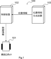
- FIG. 1 is a diagram showing a configuration example of a transport system according to an embodiment.
- the transfer system 100 includes a transfer robot 101, a control device 102, and a position information generation device 103.
- the transfer robot 101 conveys an article.
- the position information generation device 103 generates the position information of the transfer robot 101, and transmits the generated position information to the control device 102.
- the control device 102 generates control information for transporting the article by the transport robot 101 based on the position information of the transport robot 101, and transmits the generated control information to the transport robot 101.
- the transfer system 100 may include a plurality of transfer robots. In that case, the position information generation device 103 generates the position information of each of the plurality of transfer robots. Further, the control device 102 transmits control information for transporting the article to each of the plurality of transport robots.
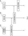
- FIG. 2 is a sequence diagram showing an operation example of the transport system according to the above embodiment.
- step S1 the position information generation device 103 generates the position information of the transfer robot 101, and transmits the generated position information to the control device 102.
- step S2 the control device 102 generates control information for transporting the article by the transport robot 101 based on the position information, and transmits the generated control information to the transport robot 101.
- step S3 the transfer robot 101 conveys the article based on the received control information.
- the transfer robot 101 can be a type of robot that puts an article on the robot itself or a type of robot that pulls an article by a towing device.
- the two transfer robots may cooperate to move (convey) the article.
- the control device 102 can control these transfer robots in consideration of not only the situation of the two transfer robots but also the surrounding environment and the like. Therefore, for example, even if an obstacle exists around the transfer robot (on the path of the transfer robot), the control device 102 can execute control to avoid the obstacle.
- the transfer robot 101 may be a type of transfer robot in which a magnetic tape or a QR code (registered trademark) is attached to the floor and the transfer robot 101 moves by relying on the magnetic tape or the like in a factory or the like. ..
- FIG. 3 is a diagram for explaining the control of the transfer robot 101 according to the embodiment.
- the transfer robot 101 deviating from the target traveling line (target line) is viewed from above.
- the target driving line is shown as a straight line, but the target driving line is not limited to the straight line.
- the path length (indicated by the broken line) for the transfer robot 101 to return to the target traveling line is minimized under predetermined conditions. Specifically, the path length (distance) from the initial position (x 0 , y 0 , ⁇ 0 ) to the target position (x a , 0, 0) on the target travel line (x axis) is minimized.
- x a is an arbitrary value.
- the predetermined conditions are as follows.
- the center of gravity velocity V can be represented by the following equation (1).
- the center-of-gravity velocity V is fixed and is set to a constant velocity.
- the angular velocity ⁇ is expressed by the following equation (2) and is limited by the maximum angular velocity ⁇ max as shown in the following equation (3).
- the limitation of the angular velocity is caused by, for example, the performance of the motor that drives the wheels of the transfer robot 101.
- the path length C from the initial position (x 0 , y 0 , ⁇ 0 ) to the target position (x a , 0, 0) on the target traveling line of the transfer robot 101 is calculated by the following equation (4).
- the time T represents the time required for the transfer robot 101 to reach the target position (x a , 0, 0) from the initial position (x 0 , y 0 , ⁇ 0 ).
- the embodiment of the present invention is not limited thereto. Further, the embodiment of the present invention is not limited to the transfer robot that conveys the article, and can be applied to a moving body configured to follow the target traveling line. In that case, the transport system is also referred to as a mobile control system.
- FIG. 4 is a diagram showing an example of a schematic configuration of a transport system according to the first embodiment.
- the transfer system 100 includes a transfer robot 101, a control device 102, a position information generation device 103, a transfer planning device 104, and a camera device 105.
- the configuration shown in FIG. 4 is an example, and does not limit the number of the transfer robot 101 and the camera device 105 included in the transfer system 100.
- the transfer robot 101 is configured to be able to communicate with the control device 102, moves based on a control command (control information) from the control device 102, and conveys an article (not shown). Further, the transfer robot 101 has a pair of drive wheels 123 arranged so that the respective axles pass through the center of gravity of the transfer robot 101.
- the camera device 105 is a device that captures an image of the field 106.
- the transport system 100 includes, for example, a depth camera, a stereo camera, and the like.
- a depth camera is a camera capable of taking a depth image in which each pixel value of an image indicates the distance from the camera to an object.
- the stereo camera is a camera capable of measuring the depth direction (height direction) of the object by photographing the object from a plurality of different directions using two cameras.
- the camera device 105 is installed on the ceiling, pillars, and the like. By integrating the image data captured by the plurality of camera devices 105, the field 106 may be overlooked.
- the camera device 105 is connected to the position information generation device 103.
- the camera device 105 images the field 106 at a predetermined interval (predetermined sampling cycle) and transmits the image data to the position information generation device 103.
- the camera device 105 captures the situation of the field 106 in real time and transmits the image data including the situation to the position information generation device 103.
- the position information generation device 103 generates information regarding the position of an object in the field 106 (for example, a factory or a distribution warehouse).
- the position information generation device 103 identifies an object located in the field 106 based on the image data received from the camera device 105, and generates position information of the object. For example, the position information generation device 103 generates the position information of the transfer robot 101.
- the position information generation device 103 analyzes the image data acquired from the camera device 105 to analyze an object in the field 106 (for example, a transport robot 101, an article to be transported, an obstacle placed in the field 106, etc.). To identify.
- the position information generation device 103 may treat an object that does not exist in the initial state of the field 106 as an “obstacle”.
- the position information generation device 103 calculates the position (absolute position) of an object in a three-dimensional coordinate system (X-axis, Y-axis, Z-axis) with an arbitrary point (for example, an entrance / exit) in the field 106 as the origin.
- the position information generation device 103 transmits the calculated position information of the object (hereinafter referred to as object position information) to the control device 102.
- the position information generation device 103 may calculate the position of the object in the two-dimensional coordinate system (X-axis, Y-axis) having an arbitrary point in the field 106 as the origin.
- the transport planning device 104 generates article transport plan information including information on the transport source and the transport destination of the article transported by the transfer robot 101. Specifically, the transport planning device 104 provides an operation screen (GUI; Graphical User Interface) for inputting a transport source and a transport destination of the article to be transported specified by the operator. The transport planning device 104 generates article transport plan information based on the information input by the GUI. The transport planning device 104 transmits the generated article transport plan information to the control device 102.
- GUI Graphical User Interface
- the control device 102 controls the transfer robot 101 by using the object position information acquired from the position information generation device 103 and the article transfer plan information acquired from the transfer planning device 104.
- the control device 102 acquires the transfer plan information
- the control device 102 selects the transfer robot 101 waiting in the field 106, and instructs the selected transfer robot 101 to go to the transfer source included in the transfer plan information. do.
- the control device 102 transmits a control command (control information) to the selected transfer robot 101, and remotely controls the transfer robot 101 so as to head toward the transfer source.
- the transfer robot 101 moves to the transfer source based on the control command from the control device 102, and when the preparation for transfer of the article is completed, the transfer robot 101 sends a "completion notification" to the control device 102.
- the control device 102 may determine that the transfer preparation by the transfer robot 101 is completed after a predetermined time (for example, 30 seconds) has elapsed after the transfer robot 101 has moved to a predetermined position.
- control device 102 When the control device 102 acquires the transfer preparation completion notification from the transfer robot 101, the control device 102 sends a control command to the transfer robot 101 so that the transfer robot 101 moves to the transfer destination included in the article transfer plan information. Remotely control.
- FIG. 5 is a diagram showing an example of the functional configuration (processing module) of the transfer robot according to the first embodiment.
- the transfer robot 101 includes a communication control unit 201, a drive unit 202, and a sensor 203.
- the communication control unit 201 is a means for controlling communication with the control device 102.
- the communication control unit 201 communicates with the control device 102 by using a wireless communication means such as a wireless LAN (Local Area Network), LTE (Long Term Evolution), or a network used in a specific area such as local 5G.
- a wireless communication means such as a wireless LAN (Local Area Network), LTE (Long Term Evolution), or a network used in a specific area such as local 5G.
- the drive unit 202 is a means for driving the two wheels of the transfer robot 101 based on the control command (control information) received from the control device 102.
- the control device 102 transmits a control command including the start of rotation of the motor, the rotation speed of the motor, the stop of rotation of the motor, and the like to the transfer robot 101.
- the drive unit 202 controls the motor and the like according to the control command to drive the two wheels of the transfer robot 101.
- the sensor 203 detects the orientation of the transfer robot 101.
- the transfer robot 101 transmits the detected information regarding the orientation of the transfer robot 101 to the control device 102 via the communication control unit 201.
- the sensor 203 can be a gyro sensor.
- FIG. 6 is a diagram showing an example of the functional configuration (processing module) of the position information generation device according to the first embodiment.
- the position information generation device 103 includes a communication control unit 301, a position information generation unit 302, and a storage unit 303.
- the communication control unit 301 is a means for controlling communication with other devices (for example, camera device 105 and control device 102) connected by wire (for example, LAN, optical fiber, etc.) or wirelessly.
- the position information generation unit 302 is a means for generating the above-mentioned object position information.
- the position information generation unit 302 generates object position information based on the image data acquired from the camera device 105.
- the camera device 105 transmits image data together with its own identifier (ID; Identifier) to the position information generation device 103.
- the position information generation device 103 identifies the camera device 105, which is the source of the image data, from the identifier.
- the camera device 105 is fixed to the ceiling or the like, and continuously transmits the image data of the field 106 to the position information generation device 103.
- the position information generation unit 302 detects an object by, for example, the following method.
- the storage unit 303 stores information in which the identifier of the camera device 105 and the area photographed by the camera device 105 are associated with each other. By referring to the corresponding information, the position information generation unit 302 can grasp an image corresponding to which area in the field 106 the acquired image data corresponds to.
- the storage unit 303 stores the initial image data of the area captured by the camera device 105.
- the initial image data is image data in which an object that does not exist in the initial state is not shown in the field 106.
- the position information generation unit 302 compares the acquired image data with the corresponding initial image data, and if there is a difference, determines that the image data includes an object to be detected.
- the object to be detected by the position information generation unit 302 includes a transfer robot 101, an article to be transferred, an obstacle placed in the passage of the field 106, and the like.
- the object discrimination by the position information generation unit 302 is not limited to the method using the above initial image data.
- the position information generation unit 302 may calculate the coordinates of the object and detect the existence of the object on the passage (on the link) based on the coordinates of the object and the normal coordinate information of the field.
- the position information generation unit 302 When the position information generation unit 302 detects an object, it approximates the object to, for example, a rectangular shape, and calculates the coordinates of the four points. Specifically, the position information generation unit 302 uses the relative coordinates (X coordinate, Y coordinate) of the object with respect to the absolute coordinates of the reference point based on the number of pixels from the reference point (for example, the lower left of the image) to the object in the image data. To calculate. At that time, the position information generation unit 302 calculates the relative coordinates of the object based on the information (resolution of the image pickup device, etc.) of the camera device 105 that has acquired the image data.
- the position information generation unit 302 calculates the relative coordinates of the object based on the information (resolution of the image pickup device, etc.) of the camera device 105 that has acquired the image data.
- the absolute coordinates of the reference point of the acquired image data are known in advance.
- the position information generation unit 302 calculates the absolute coordinates (XY coordinates) in the field of the object by adding the relative coordinates of the object calculated above to the absolute coordinates of the reference point. Further, when the image data is captured by the depth camera, the position information generation unit 302 reads out the pixel values corresponding to the calculated X and Y coordinates to obtain the Z coordinate (height) of the object. And.
- the position information generation unit 302 calculates the absolute positions of the four points forming the object by executing such processing for the four corners of the object.
- the position information generation unit 302 determines the type of the object included in the acquired image.
- the position information generation unit 302 calculates the size of the object detected from the absolute coordinates of the above four points.
- the position information generation unit 302 may determine the type of the object based on the calculated size. For example, since the size of the transfer robot 101 is known in advance, if the size of the object and the size of the transfer robot 101 match, the position information generation unit 302 determines that the detected object is the transfer robot 101. On the other hand, when the size of the detected object and the size of the transfer robot 101 do not match, the position information generation unit 302 determines that the detected object is an obstacle.
- the method of determining whether or not the robot is a transfer robot based on the size of the object is an example, and other methods can also be used. For example, even if the transfer robot 101 is detected by attaching a marker having an identification function such as a QR code (registered trademark) or an AR (Augmented Reality) marker to the transfer robot 101 and the position information generation unit 302 reading the marker. good.
- a marker is attached to the transfer robot 101, and it is described that the detected object is the transfer robot 101 and that the transfer robot 101 can be identified.
- the transfer robot 101 may be identified by the position information generation unit 302 transmitting a specific signal or message to the transfer robot 101 and the transfer robot 101 receiving the signal or the like responding with an identification number or the like. .. That is, the position information generation unit 302 can identify the transfer robot 101 by a signal or the like from the transfer robot 101 without adding identification information (for example, characters or patterns) to the outside of the transfer robot 101.
- the position information generation unit 302 transmits the detected object type (transfer robot 101, obstacle, etc.) and its absolute position to the control device 102.
- the absolute position of the object may be the absolute coordinates of the four points forming the calculated object, or may be the absolute coordinates of one point representing the object (for example, the center of the object).
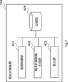
- FIG. 7 is a diagram showing an example of the functional configuration (processing module) of the transport planning device according to the first embodiment.
- the transport planning device 104 includes a communication control unit 401, a transport plan information generation unit 402, a display unit 403, and a storage unit 404.
- the communication control unit 401 is a means for controlling communication with other devices, like the communication control unit 301 of the position information generation device 103.
- the transportation plan information generation unit 402 is a means for generating the above-mentioned goods transportation plan information.
- the transport plan information generation unit 402 generates information regarding the GUI for inputting the transport source and the transport destination of the goods to be transported specified by the operator.
- the transport plan information generation unit 402 delivers the generated GUI information to the display unit 403.
- the display unit 403 displays the GUI information on the display unit 403.
- the display unit 403 can be, for example, a liquid crystal display or the like.
- the transport plan information generation unit 402 may generate information for displaying the GUI on a terminal (not shown) used by the operator, and transmit the generated information to the terminal.
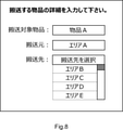
- the transport plan information generation unit 402 displays, for example, a screen as shown in FIG.
- the transport plan information generation unit 402 transmits the information input by the operator to the control device 102.
- the transport plan information generation unit 402 corresponds to information for specifying the article to be transported (for example, the article name, serial number, etc.), the place where the article is placed (transport source), and the transport destination of the article. It is attached and transmitted to the control device 102 as the article transportation plan information.
- the transport plan information generation unit 402 may convert the name in the field input by the operator into the absolute coordinates in the field, and transmit the converted absolute coordinates to the control device 102.
- FIG. 9 is a diagram showing an example of the functional configuration (processing module) of the control device according to the first embodiment.
- the control device 102 includes a communication control unit 501, a route calculation unit 502, a robot control unit 503, and a storage unit 504.
- the communication control unit 501 controls communication with other devices in the same manner as the communication control unit 401 and the like of the transfer planning device 104.
- the communication control unit 501 stores the object position information acquired from the position information generation device 103 and the article transfer plan information acquired from the transfer planning device 104 in the storage unit 504.
- the route calculation unit 502 is a means for calculating a route (for example, a target travel line) for the transport robot 101 to transport the article from the transfer source to the transfer destination based on the article transfer plan information generated by the transfer planning device 104. be.
- the route calculation unit 502 calculates a route for transporting an article from a transport source to a transport destination by using a route search algorithm such as the Dijkstra method or the Bellman-Ford method. Further, the route calculation unit 502 stores the calculated route and the transfer robot 101 using the route in the storage unit 504 in association with each other.
- the robot control unit 503 is a control means for controlling the transfer robot 101.
- the robot control unit 503 transmits control information for transporting the article by the transport robot 101 to the transport robot 101. That is, the robot control unit 503 controls the transfer robot 101 by transmitting a control command (control information) to the transfer robot 101.
- the robot control unit 503 may transmit all control commands at once so that the transfer robot 101 can move from the transfer source to the transfer destination, or the transfer commands may be sequentially transmitted according to the position of the transfer robot 101 or the like. You may send it.
- the robot control unit 503 generates a control command so that the transfer robot 101 follows and travels the route calculated by the route calculation unit 502, and transmits the control command to the transfer robot 101.
- the robot control unit 503 calculates the time and speed for rotating the motor of the transfer robot 101 according to the distance between the current position of the transfer robot 101 and the calculated arrival position.
- the robot control unit 503 When rotating (or turning) the transfer robot 101, the robot control unit 503 uses a model of circular motion that draws a curve by the speed difference between the left and right wheels. Specifically, the robot control unit 503 calculates the input speed to the left and right wheels for reaching the target position from the current position in a circular orbit based on the target position and the position and orientation of the transfer robot 101. The robot control unit 503 generates a control command to be transmitted to the transfer robot 101 based on the calculated input speed.
- the control device 102 can be implemented as a cloud server on a network (for example, a wireless communication network such as the Internet or LTE).
- a network for example, a wireless communication network such as the Internet or LTE.
- the calculation process of the left and right wheel speeds of the transfer robot 101 will be described in more detail.
- the center of gravity speed V [m / s] and the angular velocity ⁇ [rad / s] of the transfer robot 101 are used. Can be calculated.
- the center-of-gravity velocity V of the transfer robot 101 can be expressed by the following equation (5).
- the angular velocity ⁇ of the transfer robot 101 can be expressed by the following equation (6) using the distance d [m] between the left and right wheels.
- the right wheel speed v r and the left wheel speed v l can be calculated as shown in the following equations (7) and (8), respectively.
- the left and right wheel speeds can be calculated by obtaining the angular velocity ⁇ .
- the control device 102 transmits a control command to the transfer robot 101 according to the calculated left and right wheel speeds.
- the robot control unit 503 has a turning radius calculation unit 511, an angular velocity determination unit 512, and a wheel speed calculation unit 513.
- the preset center of gravity velocity V and maximum angular velocity ⁇ max can be stored in the storage unit 504 of the control device 102, and the turning radius calculation unit 511 stores the stored center of gravity velocity V and maximum angular velocity ⁇ max . It can be acquired and the turning radius R can be calculated.
- the angular velocity determination unit 512 is based on the calculated turning radius R, the target traveling line calculated by the route calculation unit 502, the position information of the transfer robot 101 acquired from the position information generation device 103, and the sensor 203 of the transfer robot 101.
- the angular velocity of the transfer robot 101 is determined using the detected direction (angle) of the transfer robot 101.
- the angular velocity is determined from among - ⁇ max , 0, + ⁇ max (ie, ternary control) using a preset maximum angular velocity ⁇ max .
- the target travel line is acquired as a vector e corresponding to the X axis.
- the position information acquired from the position information generation device 103 is converted into position information based on the target traveling line (X-axis) and used.
- the first position of the transfer robot 101 is also referred to as an initial position (x 0 , y 0 ).
- the y-coordinate of the initial position corresponds to the distance from the target traveling line (X-axis).
- the orientation of the transfer robot 101 is detected by the sensor 203 and is represented by an angle ⁇ formed by the target traveling line (X-axis) and the traveling direction of the transfer robot 101.
- the first angle ⁇ formed by the transfer robot 101 is also referred to as an initial angle ⁇ 0 .
- the angular velocity determination unit 512 determines the angular velocity ⁇ , the route for returning to the target traveling line is also determined. That is, the angular velocity determination unit 512 can function as a determination means for determining a route for returning to the target line.
- the wheel speed calculation unit 513 uses the determined angular velocity ⁇ , the center of gravity speed V, and the distance d between the left and right wheels, and the left and right wheel speeds vr as shown in the above equations (7) and (8). , V l is calculated. Further, the wheel speed calculation unit 513 transmits control information for controlling the transfer robot 101 based on the calculated left and right wheel speeds v r and v l . That is, the wheel speed calculation unit 513 can function as a control means for controlling the transfer robot 101 so that the transfer robot 101 travels on a route for returning to the target travel line.
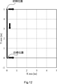
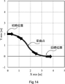
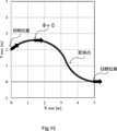
- FIGS. 12 to 19 are diagrams illustrating a specific example of a path according to an angular velocity determined by the robot control unit 503.
- the route shown in FIG. 12 is an example in the case where the angular velocity ⁇ is not limited, and is not applied in the present embodiment.
- This example is only an example when there is no limitation of the angular velocity ⁇ .
- the path for returning to the target line is configured by combining two turning paths having different angular velocities (turning directions) and one straight path.
- the two turning paths are paths in which the transfer robot 101 turns at each of two angular velocities having different positive and negative values.
- the path for returning to the target line is configured by combining two turning paths having different angular velocities (turning directions).
- FIG. 15 shows an example when the initial angle ⁇ 0 > 0.
- the range of the initial angle ⁇ 0 is 0 ⁇ 0 ⁇ ⁇ / 2
- the path for returning to the target line is configured by combining two turning paths having different angular velocities (turning directions).
- FIG. 16 to 19 show examples when the initial angle ⁇ 0 ⁇ 0, respectively.
- the example of FIG. 18 may be included in the example of the turning portion of FIG. 13 or FIG.
- the example of FIG. 19 shows an example of returning to the x-axis (target line) from the fourth quadrant of the XY coordinates after crossing the x-axis.
- the path for returning to the target line is configured by combining two turning paths having different angular velocities (turning directions) and one straight path.
- the shortest path to return to the target traveling line can be realized by controlling according to the initial position and the initial angle of the transfer robot.
- FIG. 20 is a flowchart showing an operation example of the control device according to the first embodiment. Each step of the flowchart can be carried out by the robot control unit 503 of the control device 102.
- the control device 102 calculates the turning radius R of the transfer robot 101.
- the turning radius R can be calculated as shown in the following equation (9) by using the preset center of gravity velocity V and the maximum angular velocity ⁇ max .
- the control device 102 acquires the initial position (x 0 , y 0 ) of the transfer robot 101 and the angle ⁇ 0 formed by the traveling direction of the transfer robot 101 and the target travel line.
- the control device 102 conveys based on the preset maximum angular velocity ⁇ max , the calculated turning radius R, the acquired initial position (x 0 , y 0 ), and the initial angle ⁇ 0 .
- the angular velocity ⁇ of the robot 101 is determined. The details of the angular velocity determination process will be described later.
- control device 102 calculates the left and right wheel speeds v r and v l as shown in the above equations (7) and (8) using the determined angular velocity ⁇ .
- the control device 102 transmits control information for controlling the transfer robot 101 based on the left and right wheel speeds v r and v l calculated in S104.
- the control device 102 conveys the transfer robot 101 based on the turning radius R of the transfer robot 101, the initial position (x 0 , y 0 ), and the initial angle ⁇ 0 so that the transfer robot 101 can return to the target travel line by the shortest route.
- the angular velocity ⁇ of the robot 101 is determined.
- the angular velocity ⁇ is limited by a preset maximum angular velocity ⁇ max and is determined from ⁇ max , 0, + ⁇ ma (ie, ternary control).
- the control device 102 determines whether or not the transfer robot 101 is on the target travel line based on the initial position and the initial angle of the transfer robot 101. That is, it is determined whether or not the position of the transfer robot 101 is converged on the x-axis. If it converges on the x-axis, the process ends. On the other hand, if it does not converge on the x-axis, the process proceeds to S202.
- control device 102 determines whether or not the y coordinate satisfies the relationship represented by the following equation (10).
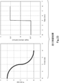
- FIG. 22 shows an example of a control result corresponding to the example of FIG.
- the angular velocity ⁇ starts at -0.5 [rad / sec], becomes 0 [rad / sec] in the straight section, and then becomes +0.5 [rad / sec]. ..
- FIG. 23 shows an example of the control result corresponding to the path in which the turning is started when the transfer robot 101 faces the direction orthogonal to the X axis. That is, FIG. 23 shows an example when there is no straight section.
- the angular velocity ⁇ starts at -0.5 [rad / sec] and is +0.5 [rad / sec] when the transfer robot 101 faces in the direction orthogonal to the X axis. ].
- FIG. 24 shows an example of a control result corresponding to the example of FIG. As shown in the graph on the right, the angular velocity ⁇ starts at -0.5 [rad / sec] and becomes +0.5 [rad / sec] at the turning point.
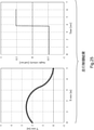
- FIG. 25 shows an example of a control result corresponding to the example of FIG.
- FIG. 26 shows an example of a control result corresponding to the example of FIG.
- the angular velocity ⁇ starts at -0.5 [rad / sec], becomes 0 [rad / sec] in the straight section, and then becomes +0.5 [rad / sec]. ..
- FIG. 27 shows an example of a control result corresponding to the example of FIG. As shown in the graph on the right, the angular velocity ⁇ starts at -0.5 [rad / sec] and becomes +0.5 [rad / sec] at the turning point.
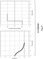
- FIG. 28 shows an example of a control result corresponding to the example of FIG. As shown in the graph on the right, the angular velocity ⁇ starts at +0.5 [rad / sec] and turns at the same angular velocity to the target traveling line.
- FIG. 29 shows an example of a control result corresponding to the example of FIG.
- the angular velocity ⁇ starts at +0.5 [rad / sec]
- turns to the side ( ⁇ 0)
- the control device 102 transports the transfer robot 101 so as to travel on a suitable route (shortest distance route) for returning to the target travel line under predetermined conditions.
- the angular velocity ⁇ of the transfer robot 101 can be determined based on the turning radius R of the robot 101, the initial position (x 0 , y 0 ), and the initial angle ⁇ 0 .
- FIG. 30 is a diagram showing an example of the hardware configuration of the control device 102.
- the control device 102 can be configured by an information processing device (so-called computer).
- the control device 102 includes a processor 311, a memory 312, an input / output interface 313, a communication interface 314, and the like.
- the components such as the processor 311 are connected by an internal bus 315 or the like and are configured to be able to communicate with each other.
- control device 102 may include hardware (not shown) or may not include an input / output interface 313 if necessary.
- number of processors 311 and the like included in the control device 102 is not limited to the example of FIG. 30, and for example, a plurality of processors 311 may be included in the control device 102.
- the processor 311 is a programmable device such as a CPU (Central Processing Unit), an MPU (Micro Processing Unit), and a DSP (Digital Signal Processor). Alternatively, the processor 311 may be a device such as an FPGA (Field Programmable Gate Array) or an ASIC (Application Specific Integrated Circuit). The processor 311 executes various programs including an operating system (OS).
- OS operating system
- the memory 312 is a RAM (RandomAccessMemory), a ROM (ReadOnlyMemory), an HDD (HardDiskDrive), an SSD (SolidStateDrive), or the like.
- the memory 312 stores an OS program, an application program, and various data.
- the input / output interface 313 is an interface of a display device or an input device (not shown).
- the display device is, for example, a liquid crystal display or the like.
- the input device is, for example, a device that accepts user operations such as a keyboard and a mouse.
- the communication interface 314 is a circuit, module, etc. that communicates with other devices.
- the communication interface 314 includes a NIC (Network Interface Card), a wireless communication circuit, and the like.
- NIC Network Interface Card
- the function of the control device 102 is realized by various processing modules.
- the processing module is realized, for example, by the processor 311 executing a program stored in the memory 312.
- the program can also be recorded on a computer-readable storage medium.
- the storage medium may be a non-transient such as a semiconductor memory, a hard disk, a magnetic recording medium, or an optical recording medium. That is, the present invention can also be embodied as a computer program product. Further, the above program can be downloaded via a network or updated by using a storage medium in which the program is stored. Further, the processing module may be realized by a semiconductor chip.
- the position information generation device 103, the transfer planning device 104, and the like can also be configured by the information processing device in the same manner as the control device 102, and the basic hardware configuration thereof is not different from that of the control device 102, so the description thereof is omitted. do.
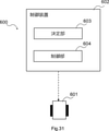
- FIG. 31 is a diagram showing an example of a schematic configuration of the mobile control system according to the second embodiment.
- the mobile body control system 600 in the present embodiment includes a mobile body 601 and a control device 602 that controls the mobile body 601 so as to follow the target line.
- the control device 602 includes a determination unit 603 and a control unit 604.
- the determination unit 603 includes a turning path with the turning radius based on the turning radius of the moving body 601 and the distance between the moving body 601 and the target line, and the angle formed by the traveling direction of the moving body 601 and the target line. , Determine the route to return to the target line.
- the control unit 604 controls the moving body 601 so that the moving body 601 travels on the above route.
- the above-mentioned processing unit is realized by, for example, a CPU (Central Processing Unit) of a computer that operates according to a program, and a communication interface of the computer.
- the CPU reads a program from a program recording medium (a non-transitory recording medium that can be read by a computer) such as a program storage device of the computer, and uses a communication interface as necessary according to the program. Therefore, it can operate as each processing unit of each of the above-mentioned devices.
- a program recording medium a non-transitory recording medium that can be read by a computer
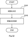
- FIG. 32 is a flowchart showing an operation example of the control device according to the second embodiment.
- the control device 602 (decision unit 603) is based on the turning radius of the moving body 601, the distance between the moving body 601 and the target line, and the angle formed by the traveling direction of the moving body 601 and the target line. Then, the route for returning to the target line is determined, including the turning path with the turning radius.
- control device 602 controls the moving body 601 so that the moving body 601 travels on the above route.
- the mobile control system 600 in the second embodiment is the transport system 100 in the first embodiment.
- the description of the first embodiment may also be applied to the second embodiment.
- the second embodiment is not limited to this example.
- the function of the position information generation device 103 may be realized by the control device 102.
- the position information generation device 103 may execute a process related to the determination of the position of the object, and the control device 102 may determine the type of the object.
- the location information generation device 103 may be installed inside the field, and the control device 102 may be mounted on a server on the network. That is, the transport system disclosed in the present application may be realized as an edge cloud system.
- a camera capable of detecting the height of the object for example, a depth camera
- a normal camera may be used.
- an infrared sensor or a distance sensor may be used as a sensor for detecting the position of an object.
- the control device is The target including a turning path with the turning radius based on the turning radius of the moving body, the distance between the moving body and the target line, and the angle formed by the traveling direction of the moving body and the target line. Determine the route to return to the line,
- a moving body control system characterized in that the moving body is controlled so that the moving body travels on the path.
- Appendix 2 The mobile control system according to Appendix 1, wherein the route further includes a straight route in a direction orthogonal to the target line.
- Appendix 3 The mobile control system according to Appendix 2, wherein the straight path is included in the path when y> 2R, where y is the distance and R is the turning radius.
- Appendix 6 The mobile control system according to Appendix 5, wherein the angular velocity is limited to a predetermined range.
- the turn is based on the turning radius of the moving body controlled to follow the target line, the distance between the moving body and the target line, and the angle formed by the traveling direction of the moving body and the target line.
- a control device comprising a control means for controlling the moving body so that the moving body travels on the path.
- Appendix 10 The control device according to Appendix 9, wherein the route further includes a straight route in a direction orthogonal to the target line.
- Appendix 11 The control device according to Appendix 10, wherein the straight path is included in the path when y> 2R, where y is the distance and R is the turning radius.
- Appendix 14 The control device according to Appendix 13, wherein the angular velocity is limited to a predetermined range.
- the turn is based on the turning radius of the moving body controlled to follow the target line, the distance between the moving body and the target line, and the angle formed by the traveling direction of the moving body and the target line.
- a decision step that determines the path to return to the target line, including a turning path by radius.
- a moving body control method comprising a control step for controlling the moving body so that the moving body travels on the path.
- Appendix 17 The moving body control method according to Appendix 16, wherein the route further includes a straight route in a direction orthogonal to the target line.
- Appendix 18 The moving body control method according to Appendix 17, wherein the straight path is included in the path when y> 2R, where y is the distance and R is the turning radius.
- Appendix 21 The moving body control method according to Appendix 20, wherein the angular velocity is limited to a predetermined range.
- the present invention is suitably applicable to the transportation of goods such as factories and distribution warehouses.
Landscapes
- Engineering & Computer Science (AREA)
- Radar, Positioning & Navigation (AREA)
- Physics & Mathematics (AREA)
- Aviation & Aerospace Engineering (AREA)
- Remote Sensing (AREA)
- General Physics & Mathematics (AREA)
- Automation & Control Theory (AREA)
- Computer Vision & Pattern Recognition (AREA)
- Multimedia (AREA)
- Electromagnetism (AREA)
- Control Of Position, Course, Altitude, Or Attitude Of Moving Bodies (AREA)
Priority Applications (2)
| Application Number | Priority Date | Filing Date | Title |
|---|---|---|---|
| US18/020,538 US12386356B2 (en) | 2020-08-25 | 2021-06-03 | Moving body control system, control apparatus, and moving body control method |
| JP2022545326A JP7501643B2 (ja) | 2020-08-25 | 2021-06-03 | 移動体制御システム、制御装置、及び、移動体制御方法 |
Applications Claiming Priority (2)
| Application Number | Priority Date | Filing Date | Title |
|---|---|---|---|
| JP2020-142065 | 2020-08-25 | ||
| JP2020142065 | 2020-08-25 |
Publications (1)
| Publication Number | Publication Date |
|---|---|
| WO2022044473A1 true WO2022044473A1 (ja) | 2022-03-03 |
Family
ID=80353100
Family Applications (1)
| Application Number | Title | Priority Date | Filing Date |
|---|---|---|---|
| PCT/JP2021/021115 Ceased WO2022044473A1 (ja) | 2020-08-25 | 2021-06-03 | 移動体制御システム、制御装置、及び、移動体制御方法 |
Country Status (3)
| Country | Link |
|---|---|
| US (1) | US12386356B2 (https=) |
| JP (1) | JP7501643B2 (https=) |
| WO (1) | WO2022044473A1 (https=) |
Citations (2)
| Publication number | Priority date | Publication date | Assignee | Title |
|---|---|---|---|---|
| JP2002132344A (ja) * | 2000-10-24 | 2002-05-10 | Nippon Seiki Co Ltd | 移動体の誘導方法 |
| JP2014219782A (ja) * | 2013-05-07 | 2014-11-20 | 第一施設工業株式会社 | 自立走行装置 |
Family Cites Families (8)
| Publication number | Priority date | Publication date | Assignee | Title |
|---|---|---|---|---|
| JPS61112215A (ja) | 1984-11-06 | 1986-05-30 | Komatsu Ltd | 無人車両の旋回制御方法 |
| JP2920017B2 (ja) | 1992-03-11 | 1999-07-19 | 新キャタピラー三菱株式会社 | 走行体のコース学習誘導方法およびその装置 |
| US6134486A (en) | 1998-04-20 | 2000-10-17 | The United States Of America As Represented By The Secretary Of The Navy | Robot and method of control for an autonomous vehicle to track a path consisting of directed straight lines and circles with positional feedback and continuous curvature |
| US9789869B2 (en) * | 2012-11-02 | 2017-10-17 | Toyota Jidosha Kabushiki Kaisha | Driving support apparatus and driving support method |
| JP2015055906A (ja) | 2013-09-10 | 2015-03-23 | 株式会社日立産機システム | 移動体の走行制御手段に対して制御指令を出力する位置検出装置及び移動体システム |
| US10390474B2 (en) * | 2017-06-19 | 2019-08-27 | Cnh Industrial America Llc. | Path planning system for a work vehicle |
| CN115136091B (zh) * | 2020-02-27 | 2025-07-29 | 三菱重工业株式会社 | 控制装置、移动体、移动控制系统、控制方法及存储介质 |
| CN111764235B (zh) * | 2020-06-19 | 2022-02-18 | 三一汽车制造有限公司 | 工程机械转弯控制方法、工程机械和计算机设备 |
-
2021
- 2021-06-03 US US18/020,538 patent/US12386356B2/en active Active
- 2021-06-03 JP JP2022545326A patent/JP7501643B2/ja active Active
- 2021-06-03 WO PCT/JP2021/021115 patent/WO2022044473A1/ja not_active Ceased
Patent Citations (2)
| Publication number | Priority date | Publication date | Assignee | Title |
|---|---|---|---|---|
| JP2002132344A (ja) * | 2000-10-24 | 2002-05-10 | Nippon Seiki Co Ltd | 移動体の誘導方法 |
| JP2014219782A (ja) * | 2013-05-07 | 2014-11-20 | 第一施設工業株式会社 | 自立走行装置 |
Also Published As
| Publication number | Publication date |
|---|---|
| JP7501643B2 (ja) | 2024-06-18 |
| US12386356B2 (en) | 2025-08-12 |
| US20230297121A1 (en) | 2023-09-21 |
| JPWO2022044473A1 (https=) | 2022-03-03 |
Similar Documents
| Publication | Publication Date | Title |
|---|---|---|
| CN112631269B (zh) | 自主移动机器人及自主移动机器人的控制程序 | |
| KR101539270B1 (ko) | 충돌회피 및 자율주행을 위한 센서융합 기반 하이브리드 반응 경로 계획 방법, 이를 수행하기 위한 기록 매체 및 이동로봇 | |
| JP7416072B2 (ja) | 搬送システム、制御装置、及び搬送方法 | |
| JP7559883B2 (ja) | 搬送システム、制御装置、搬送方法及びプログラム | |
| CN106541404A (zh) | 一种机器人视觉定位导航方法 | |
| US11112780B2 (en) | Collaborative determination of a load footprint of a robotic vehicle | |
| EP4024155B1 (en) | Method, system and computer program product of control of unmanned aerial vehicles | |
| CN111857114A (zh) | 一种机器人编队移动方法、系统、设备和存储介质 | |
| KR102892772B1 (ko) | 포인트-라인 피처를 이용한 슬램의 최적화 방법 및 장치 | |
| Irwansyah et al. | ROS-based multi-sensor integrated localization system for cost-effective and accurate indoor navigation system | |
| Medjaldi et al. | Cost-Effective Real-Time Obstacle Detection and Avoidance for AGVs using YOLOv8 and RGB-D Sensors | |
| Pussente et al. | Advanced drone-based powerline inspection using image segmentation and adaptive visual control | |
| JP7563455B2 (ja) | 移動体制御システム、制御装置、及び、移動体制御方法 | |
| JP7501643B2 (ja) | 移動体制御システム、制御装置、及び、移動体制御方法 | |
| JP2020042516A (ja) | 移動経路生成装置、移動装置、移動経路生成方法、及びプログラム | |
| Atali et al. | Path planning of mobile robots based on qr code | |
| CN113837332B (zh) | 货架角度调整方法、装置、电子设备和计算机可读介质 | |
| WO2021039212A1 (ja) | システム、位置情報管理装置、位置特定方法及びプログラム | |
| CN121563366B (zh) | 机器人的自主转运方法、设备和存储介质 | |
| Nandikolla et al. | Navigation and path planning of an autonomous mobile robot | |
| CN112241165B (zh) | 用于控制无人设备的方法和装置 | |
| EP4689711A1 (en) | 3d sensor-based obstacle detection for autonomous vehicles and mobile robots | |
| Nagata et al. | Autonomous Flight and Path Planning for an Indoor Inspection Drone Using LiDAR | |
| TW202610925A (zh) | 用於判定貨櫃輪之貨櫃艙上之貨櫃位置的方法、控制器、定位裝置及電腦程式 | |
| Devaraju | Dynamic AGV routing depending on sensor-based collision avoidance: A case |
Legal Events
| Date | Code | Title | Description |
|---|---|---|---|
| 121 | Ep: the epo has been informed by wipo that ep was designated in this application |
Ref document number: 21860904 Country of ref document: EP Kind code of ref document: A1 |
|
| ENP | Entry into the national phase |
Ref document number: 2022545326 Country of ref document: JP Kind code of ref document: A |
|
| NENP | Non-entry into the national phase |
Ref country code: DE |
|
| 122 | Ep: pct application non-entry in european phase |
Ref document number: 21860904 Country of ref document: EP Kind code of ref document: A1 |
|
| WWG | Wipo information: grant in national office |
Ref document number: 18020538 Country of ref document: US |