WO2022044432A1 - Dispositif de commande électronique - Google Patents
Dispositif de commande électronique Download PDFInfo
- Publication number
- WO2022044432A1 WO2022044432A1 PCT/JP2021/017531 JP2021017531W WO2022044432A1 WO 2022044432 A1 WO2022044432 A1 WO 2022044432A1 JP 2021017531 W JP2021017531 W JP 2021017531W WO 2022044432 A1 WO2022044432 A1 WO 2022044432A1
- Authority
- WO
- WIPO (PCT)
- Prior art keywords
- control device
- circuit
- electronic control
- external
- output
- Prior art date
Links
- 239000003990 capacitor Substances 0.000 claims description 20
- 239000004065 semiconductor Substances 0.000 claims description 4
- 238000003745 diagnosis Methods 0.000 abstract description 15
- 238000011084 recovery Methods 0.000 abstract description 2
- 230000000717 retained effect Effects 0.000 abstract 1
- CNQCVBJFEGMYDW-UHFFFAOYSA-N lawrencium atom Chemical compound [Lr] CNQCVBJFEGMYDW-UHFFFAOYSA-N 0.000 description 22
- 238000010586 diagram Methods 0.000 description 14
- 206010014357 Electric shock Diseases 0.000 description 4
- 238000000605 extraction Methods 0.000 description 4
- 238000000034 method Methods 0.000 description 4
- HBBGRARXTFLTSG-UHFFFAOYSA-N Lithium ion Chemical compound [Li+] HBBGRARXTFLTSG-UHFFFAOYSA-N 0.000 description 3
- 229910001416 lithium ion Inorganic materials 0.000 description 3
- 230000000694 effects Effects 0.000 description 2
- 238000005516 engineering process Methods 0.000 description 2
- 230000006378 damage Effects 0.000 description 1
- 239000000284 extract Substances 0.000 description 1
- 230000007257 malfunction Effects 0.000 description 1
- 238000012986 modification Methods 0.000 description 1
- 230000004048 modification Effects 0.000 description 1
- 230000002093 peripheral effect Effects 0.000 description 1
Images


Classifications
-
- B—PERFORMING OPERATIONS; TRANSPORTING
- B60—VEHICLES IN GENERAL
- B60L—PROPULSION OF ELECTRICALLY-PROPELLED VEHICLES; SUPPLYING ELECTRIC POWER FOR AUXILIARY EQUIPMENT OF ELECTRICALLY-PROPELLED VEHICLES; ELECTRODYNAMIC BRAKE SYSTEMS FOR VEHICLES IN GENERAL; MAGNETIC SUSPENSION OR LEVITATION FOR VEHICLES; MONITORING OPERATING VARIABLES OF ELECTRICALLY-PROPELLED VEHICLES; ELECTRIC SAFETY DEVICES FOR ELECTRICALLY-PROPELLED VEHICLES
- B60L3/00—Electric devices on electrically-propelled vehicles for safety purposes; Monitoring operating variables, e.g. speed, deceleration or energy consumption
- B60L3/0023—Detecting, eliminating, remedying or compensating for drive train abnormalities, e.g. failures within the drive train
- B60L3/0084—Detecting, eliminating, remedying or compensating for drive train abnormalities, e.g. failures within the drive train relating to control modules
-
- B—PERFORMING OPERATIONS; TRANSPORTING
- B60—VEHICLES IN GENERAL
- B60L—PROPULSION OF ELECTRICALLY-PROPELLED VEHICLES; SUPPLYING ELECTRIC POWER FOR AUXILIARY EQUIPMENT OF ELECTRICALLY-PROPELLED VEHICLES; ELECTRODYNAMIC BRAKE SYSTEMS FOR VEHICLES IN GENERAL; MAGNETIC SUSPENSION OR LEVITATION FOR VEHICLES; MONITORING OPERATING VARIABLES OF ELECTRICALLY-PROPELLED VEHICLES; ELECTRIC SAFETY DEVICES FOR ELECTRICALLY-PROPELLED VEHICLES
- B60L3/00—Electric devices on electrically-propelled vehicles for safety purposes; Monitoring operating variables, e.g. speed, deceleration or energy consumption
- B60L3/0007—Measures or means for preventing or attenuating collisions
-
- B—PERFORMING OPERATIONS; TRANSPORTING
- B60—VEHICLES IN GENERAL
- B60L—PROPULSION OF ELECTRICALLY-PROPELLED VEHICLES; SUPPLYING ELECTRIC POWER FOR AUXILIARY EQUIPMENT OF ELECTRICALLY-PROPELLED VEHICLES; ELECTRODYNAMIC BRAKE SYSTEMS FOR VEHICLES IN GENERAL; MAGNETIC SUSPENSION OR LEVITATION FOR VEHICLES; MONITORING OPERATING VARIABLES OF ELECTRICALLY-PROPELLED VEHICLES; ELECTRIC SAFETY DEVICES FOR ELECTRICALLY-PROPELLED VEHICLES
- B60L3/00—Electric devices on electrically-propelled vehicles for safety purposes; Monitoring operating variables, e.g. speed, deceleration or energy consumption
- B60L3/04—Cutting off the power supply under fault conditions
Definitions
- the present invention relates to the configuration of an in-vehicle electronic control device, and particularly relates to a technique effective for being applied to an electronic control device mounted on an electric vehicle such as a hybrid vehicle or an electric vehicle.
- HEV Hybrid Electric Vehicle
- EV Electric Vehicle
- a high voltage power supply of about 400V is supplied from a lithium ion battery to an inverter in order to operate a motor. If the high-voltage power supply line comes into contact with the body of the vehicle in the event of a collision, there is a risk of electric shock by touching the vehicle.
- HEV vehicles use a lithium-ion battery and a relay between the loads to control the high-voltage power supply line to be cut off except when the vehicle is in operation.
- Patent Document 1 describes "a power supply circuit mounted on a vehicle and having a battery, a load and a relay, a relay control unit that controls the relay to connect and detach the battery and the load, and the above in the event of a vehicle collision.
- a power supply cutoff device having a breaking mechanism for separating a battery and a load by breaking a signal line provided between a relay control unit and the relay is disclosed.
- HEV vehicles use relays between the lithium-ion battery and the load, but the relays are controlled due to the failure of the circuit parts that control the relays or the destruction of the unit due to a vehicle collision. There is a possibility that an ON failure may occur in which the relay is stuck in the ON state and cannot be turned OFF due to a short circuit between the output circuit and the peripheral circuit.
- Patent Document 1 discloses a technique for forcibly shutting off a relay by cutting a high voltage power supply line with a cutting blade when a vehicle collides.
- the high-voltage power supply line can be reliably cut off in the event of a vehicle collision, but since the harness is disconnected even when the relay is ON and has not failed, it is necessary to replace the harness even in the case of a malfunction or a minor collision. Occurs. In addition, it is not possible to prevent a relay ON failure due to a circuit failure.
- an object of the present invention is the reliability and convenience of an electronic control device mounted on an electric vehicle, which can be easily restored while reliably shutting off the high voltage power supply line in the event of a vehicle collision or failure of the power cutoff circuit.
- An object of the present invention is to provide an electronic control device having excellent properties.
- the present invention presents an external load switching element for driving an external load, a control device for driving the external load switching element, a connection between an internal GND and an external GND, or an internal power supply system and an external power supply system.
- a transistor for cutting off the connection a diagnostic circuit of a control circuit that controls the external load by the external load switching element, and a diagnostic circuit that outputs a diagnostic result by inputting a diagnostic signal of the control device, and the diagnosis.
- An output holding circuit that holds the output signal of the circuit is provided, and the connection between the internal GND and the external GND or the connection between the internal power supply system and the external power supply system is cut off by the breaking transistor based on the signal held by the output holding circuit. It is characterized by that.
- the present invention in an electronic control device mounted on an electric vehicle, in the event of a vehicle collision or a failure of a power cutoff circuit, the high voltage power supply line is surely cut off, and the reliability and convenience of easy recovery are achieved.
- An excellent electronic control device can be realized.
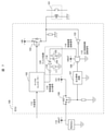
- FIG. 1 is a schematic configuration diagram of the electronic control device of this embodiment.
- the electronic control unit (ECU: Electronic Control Unit) 100 of this embodiment has an external load switching element 103 for driving an external load 101 and a micro for driving an external load switching element 103.
- a control device 102 such as a controller is provided.
- the control device diagnostic signal 114 from the control device 102 is input to the NOR circuit 106 through filters such as a filter capacitor 104 and a filter resistor 105 so as to be HI at normal times. Further, the output control circuit diagnostic signal 115 is input to the NOR circuit 106 as a signal that becomes LO when the external load 101 is turned on.
- the electronic control unit (ECU) 100 includes an output holding circuit 107 for holding the output from the NOR circuit 106, and a charge extraction transistor 108 for extracting the gate charge of the breaking transistor 109.
- the breaking transistor 109 has a function of cutting off an external GND (vehicle GND) 111 of a vehicle or the like and an ECU internal GND (ECU GND) 112.
- the effect of GND cutoff can be controlled by whether the vehicle GND111 or ECU GND112 is used as the GND in the electronic control unit (ECU) 100, but in order to maintain the cutoff state after the cutoff, the GND of the output holding circuit 107 and The GND of the charge extraction transistor 108 is shared with the external GND (vehicle GND) 111.
- the controller diagnostic signal 114 is LO-output until the controller 102 such as a microcontroller is activated.
- the output control circuit diagnostic signal 115 is pulled up by the battery voltage VBAT110, the HI output is maintained.
- the NOR circuit 106 outputs LO and the output holding circuit 107 also outputs LO, so that the charge extraction transistor 108 is turned off. Since the breaking transistor 109 is turned on by the battery voltage VBAT110, the ECU internal GND 112 is connected to the external GND 111 of the vehicle or the like.
- the control device diagnosis signal 114 is HI output. Since the NOR circuit 106 maintains the LO output, the breaking transistor 109 keeps ON, and the ECU internal GND 112 maintains the connection with the external GND 111 of the vehicle or the like.
- the output control circuit signal 115 is output in LO. Since the control device diagnostic signal 114 is HI and the NOR circuit 106 maintains the LO output, the breaking transistor 109 keeps ON, and the ECU internal GND 112 maintains the connection with the external GND 111 of the vehicle or the like.
- the output control circuit diagnostic signal 115 is HI and the external load 101.
- the NOR circuit 106 maintains the LO output, so that the breaking transistor 109 is kept ON, and the ECU internal GND 112 maintains the connection with the external GND 111 of the vehicle or the like.
- control device diagnostic signal 114 is LO due to a failure of the internal circuit of the electronic control device (ECU) 100 or an external signal (collision signal) 113 from the outside
- the output control circuit diagnostic signal 115 Is LO, so the NOR circuit 106 is HI.
- the charge extraction transistor 108 receives the HI output of the output holding circuit 107, turns on, and extracts the gate voltage of the breaking transistor 109. Since the breaking transistor 109 is turned off, the connection between the internal GND 112 of the ECU and the external GND 111 of the vehicle or the like is cut off.
- the external load 101 is cut off from the path through which the current flows to the external GND 111 of the vehicle or the like through the external load switching element 103, so that the external load 101 is cut off. ..
- the control device diagnostic signal 114 not only fails in the internal circuit or the like, but also receives a signal from an ECU different from the electronic control unit (ECU) 100 and outputs the control device diagnostic signal 114 as an LO output to obtain an external load 101. It can also be used to prevent ON failures.
- the cutoff transistor 109 that cuts off the internal GND 112 of the ECU and the external GND 111 of the vehicle or the like is held off by the output holding circuit 107, the battery voltage VBAT110 supplied to the electronic control unit (ECU) 100 is once turned off. By turning it on again, the holding of the output holding circuit 107 is released, so that the external load 101 can be turned on again.
- the electronic control device (ECU) 100 of this embodiment includes an external load switching element 103 for driving an external load 101, a control device 102 for driving an external load switching element 103, an ECU internal GND 112, and a vehicle.
- a breaking transistor 109 that cuts off the connection of the external GND 111 such as the above, a diagnostic signal of the control circuit that controls the external load 101 by the external load switching element 103 (output control circuit diagnostic signal 115), and a diagnostic signal of the control device 102 (control). It is provided with a diagnostic circuit (NOR circuit 106) that receives a device diagnostic signal 114) as an input and outputs a diagnostic result, and an output holding circuit 107 that holds an output signal of the diagnostic circuit (NOR circuit 106). Based on the held signal, the disconnection transistor 109 cuts off the connection between the internal GND 112 of the ECU and the external GND 111 of the vehicle or the like.
- the ON failure of the external load 101 is based on the diagnostic signal of the control circuit (output control circuit diagnostic signal 115) that controls the external load 101 by the external load switching element 103 and the diagnostic signal of the control device 102 (control device diagnostic signal 114). Is detected.
- the external load 101 is a relay that controls the high voltage power supply line, it is possible to prevent electric shock even if the high voltage power supply line comes into contact with the body by surely shutting off.
- FIG. 3 is a schematic configuration diagram of the electronic control device of this embodiment.
- the electronic control device (ECU) 100 of this embodiment has a filter capacitor 104, 118 and a filter resistor 105 for the control device diagnosis signal 114 with respect to the first embodiment (FIG. 1).
- 117 and a filter circuit 120 using a filter diode 116 and the like have been added.
- Other configurations are the same as those in the first embodiment (FIG. 1).
- the purpose of the filter circuit 120 is to exclude the DC component by the filter capacitor 118.
- the PWM output is input as the input of the filter circuit 120, the voltage is divided between the filter capacitor 118 and other circuits at the time of PWM HI input, and the electric charge is accumulated in the filter capacitor 104.
- the electric charge of the filter capacitor 118 is discharged through the filter resistor 117. Since the charge of the filter capacitor 104 is limited to the filter diode 116, no charge is emitted from the filter resistor 117.
- the filter output becomes HI output.
- the controller output signal 119 outputs PWM in the normal state.
- the controller diagnostic signal 114 becomes HI through the filter circuit 120.
- control device diagnosis signal 114 becomes LO by the filter circuit 120.
- control device diagnosis signal 114 becomes LO, so that if the external load 101 turns ON and fails, it is cut off. It becomes possible to do.
- the electronic control device (ECU) 100 of this embodiment includes a filter circuit 120 composed of filter capacitors 104 and 118, filter resistors 105 and 117, and filter diode 116.
- the filter circuit 120 is connected between the control device 102 and the diagnostic circuit (NOR circuit 106). Then, the PWM output from the control device 102 is excluded from the DC component output from the control device 102 via the filter circuit 120, and the diagnostic circuit (NOR circuit 106) is used as the diagnostic signal (control device diagnostic signal 114) of the control device 102. ).
- the PWM output from the control device 102 is stopped, and then the ECU internal GND 112 and the vehicle external GND 111 are used. Controls the time it takes to disconnect.
- FIG. 4 is a schematic configuration diagram of the electronic control device of this embodiment.
- the filter circuit 120 is located between the control device 102 such as a microcontroller and the external load switching element 103 with respect to the first embodiment (FIG. 1). Has been added.
- Other configurations are the same as those in the first embodiment (FIG. 1).
- the electronic control device (ECU) 100 of this embodiment includes a filter circuit 120 composed of filter capacitors 104 and 118, filter resistors 105 and 117, and a filter diode 116.
- the filter circuit 120 is connected between the control device 102 and the external load switching element 103.
- the gate voltage of the external load switching element 103 becomes HI, the external load switching element 103 turns on, and the external load 101 can be turned on.
- control device diagnosis signal 114 becomes LO output, so that the external load 101 fails to turn ON and the output control circuit diagnosis signal 115 becomes LO.
- breaking transistor 109 it is possible to cut off the current path of the external load 101 and prevent the external load 101 from failing to turn on.
- FIG. 5 is a schematic configuration diagram of the electronic control device of this embodiment.
- the electronic control unit (ECU) 100 of the present embodiment does not output the control device diagnosis signal 114 from the control device 102 but the electronic control unit (ECU) with respect to the first embodiment (FIG. 1). ) It is directly input from 100 external signals.
- the control device diagnostic signal 114 may be configured to be input to the NOR circuit 106 via the filter circuit 120 as in the second embodiment (FIG. 3).
- the electronic control unit (ECU) 100 of the present embodiment has an external signal 113 (for example, a vehicle collision signal) input from the outside as a diagnostic signal (control device diagnostic signal 114) of the control device 102. Is used.
- the external controller (not shown) of the electronic control unit (ECU) 100 makes it possible to forcibly turn off the ON state of the external load 101.
- FIG. 6 is a schematic configuration diagram of the electronic control device of this embodiment.
- the external load 101 is configured such that a current flows through the external load switching element 103 to the external GND 111 of the vehicle or the like. As shown in FIG. 6, the electrons of the present embodiment are configured.
- the control device (ECU) 100 is a method of controlling the external load 101 by supplying the ECU power supply VB 121 of the electronic control device (ECU) 100 to the external load 101.
- the ECU power supply VB121 is supplied to the external load 101, so that the output control circuit diagnostic signal 115 becomes LO due to the NOT circuit 122.
- the control circuit diagnostic signal 114 is LO, the NOR circuit 106 becomes HI.
- control device diagnostic signal 114 may be configured to use the external signal 113 as in the fourth embodiment.
- the breaking transistor 109 Since the HI input of the NOR circuit 106 is held by the output holding circuit 107, the breaking transistor 109 is turned off, so that the connection between the battery voltage VBAT110 and the ECU power supply VB121 is cut off.
- the power supply of the ECU power supply VB121 is cut off, the output of the external load 101 is cut off, so that the external load 101 is cut off.
- the diagnostic circuits are the NOT circuit 122 and the NOR circuit 106, and the external load 101 is subjected to the internal power supply voltage (ECU power supply) by the external load switching element 103.
- the diagnostic signal of the control circuit (output control circuit diagnostic signal 115) controlled by VB121) is input to the NOR circuit 106 via the NOT circuit 122, and the diagnostic signal of the control device 102 (control device diagnostic signal 114) is input to the NOR circuit 106.
- the connection between the internal power supply system (ECU power supply VB121) and the external power supply system (battery voltage VBAT110) is cut off by the cutoff transistor 109 based on the output signal of the NOR circuit 106 which is input and held by the output holding circuit 107.
- FIG. 7 is a schematic configuration diagram of the electronic control device of this embodiment.
- the electronic control device (ECU) 100 of this embodiment has a filter capacitor 104, 118 and a filter resistor 105 for the control device diagnosis signal 114 with respect to the fifth embodiment (FIG. 6).
- 117 and a filter circuit 120 using a filter diode 116 and the like have been added.
- Other configurations are the same as in Example 5 (FIG. 6).
- the electronic control device (ECU) 100 of this embodiment includes a filter circuit 120 composed of filter capacitors 104 and 118, filter resistors 105 and 117, and filter diode 116.
- the PWM output from the control device 102 is excluded from the DC component output from the control device 102 via the filter circuit 120, and is input to the NOR circuit 106 as a diagnostic signal (control device diagnostic signal 114) of the control device 102.
- control device diagnosis signal 114 becomes LO, so that if the external load 101 turns ON and fails, it is cut off. It becomes possible to do.
- FIG. 8 is a schematic configuration diagram of the electronic control device of this embodiment.
- the filter circuit 120 is located between the control device 102 such as a microcontroller and the external load switching element 103 with respect to the fifth embodiment (FIG. 6).
- the AND circuit 123 is connected in place of the NOR circuit 106 and the NOT circuit 122 of the fifth embodiment (FIG. 6).
- Other configurations are the same as in Example 5 (FIG. 6).
- the electronic control device (ECU) 100 of the present embodiment includes a filter circuit 120 composed of filter capacitors 104 and 118, filter resistors 105 and 117, and a filter diode 116.
- the filter circuit 120 is connected between the control device 102 and the external load switching element 103, the diagnostic circuit is the AND circuit 123, and the PWM output from the control device 102 is transmitted from the control device 102 via the filter circuit 120.
- the output DC component is excluded, and the DC component is input to the AND circuit 123 as a diagnostic signal of the control device 102 (control device diagnostic signal 114), and the cutoff transistor 109 is used based on the output signal of the AND circuit 123 held by the output holding circuit 107.
- the connection between the internal power supply system (ECU power supply VB121) and the external power supply system (battery voltage VBAT110) is cut off.
- the gate voltage of the external load switching element 103 becomes LO, the external load switching element 103 turns on, and the external load 101 can be turned on.
- the control device diagnostic signal 114 outputs HI, so that the external load 101 fails to turn ON and the output control circuit diagnostic signal 115 becomes HI.
- the HI output is output by the AND circuit 123, the HI output is held by the output holding circuit 107, and the breaking transistor 109 is turned off to cut off the current path of the external load 101 and prevent the external load 101 from failing to turn on. It becomes possible.
- the diagnostic circuits (NOR circuit 106, NOT circuit 122, AND circuit 123) and the output holding circuit 107 described in each of the above embodiments use at least semiconductor elements in which these circuits are formed on the same semiconductor chip. Is desirable. By forming the diagnostic circuit and the output holding circuit 107 on the same semiconductor chip, the wiring delay between the two circuits is eliminated, and the breaking transistor 109 can be operated without delay.
- the present invention is not limited to the above-described embodiment, and includes various modifications.
- the above embodiments have been described in detail to aid in understanding of the present invention and are not necessarily limited to those comprising all of the described configurations.
- ECU Electronice control device
- 101 External load
- 102 External load switching element
- 103 External load switching element
- 104 External load switching element
- 104 External load switching element
- 104 External load switching element
- 104 External load switching element
- 104 Filter capacitor
- 105 External Filter resistor
- 106 ... NOR circuit
- 107 ... Output holding circuit
- 108 ... Transistor for extracting charge
- 109 ... Transistor for breaking, 110 ... Battery voltage (VBAT)
- 111 External GND of vehicle (vehicle GND), 112 ... ECU internal GND (ECU GND), 113 ... External signal (collision signal),
- 114 ... Control device diagnostic signal
- 115 ... Output control circuit diagnostic signal 116 ... Filter transistor, 117 ... Filter resistor, 118 ... Filter capacitor, 119 ... Control device (micro controller, etc.)
- Output signal 120 ... filter circuit, 121 ... ECU power supply (VB),
Landscapes
- Engineering & Computer Science (AREA)
- Life Sciences & Earth Sciences (AREA)
- Sustainable Development (AREA)
- Sustainable Energy (AREA)
- Power Engineering (AREA)
- Transportation (AREA)
- Mechanical Engineering (AREA)
- Electronic Switches (AREA)
Abstract
Priority Applications (4)
| Application Number | Priority Date | Filing Date | Title |
|---|---|---|---|
| JP2022545306A JP7492588B2 (ja) | 2020-08-24 | 2021-05-07 | 電子制御装置 |
| US18/022,714 US20240034151A1 (en) | 2020-08-24 | 2021-05-07 | Electronic control unit |
| EP21860864.4A EP4201751A1 (fr) | 2020-08-24 | 2021-05-07 | Dispositif de commande électronique |
| CN202180051590.9A CN115943093A (zh) | 2020-08-24 | 2021-05-07 | 电子控制装置 |
Applications Claiming Priority (2)
| Application Number | Priority Date | Filing Date | Title |
|---|---|---|---|
| JP2020140687 | 2020-08-24 | ||
| JP2020-140687 | 2020-08-24 |
Publications (1)
| Publication Number | Publication Date |
|---|---|
| WO2022044432A1 true WO2022044432A1 (fr) | 2022-03-03 |
Family
ID=80353001
Family Applications (1)
| Application Number | Title | Priority Date | Filing Date |
|---|---|---|---|
| PCT/JP2021/017531 WO2022044432A1 (fr) | 2020-08-24 | 2021-05-07 | Dispositif de commande électronique |
Country Status (4)
| Country | Link |
|---|---|
| US (1) | US20240034151A1 (fr) |
| EP (1) | EP4201751A1 (fr) |
| CN (1) | CN115943093A (fr) |
| WO (1) | WO2022044432A1 (fr) |
Citations (5)
| Publication number | Priority date | Publication date | Assignee | Title |
|---|---|---|---|---|
| JP2000247552A (ja) * | 1999-02-25 | 2000-09-12 | Mitsubishi Electric Corp | エレベーターのブレーキ制御装置 |
| JP2004159439A (ja) * | 2002-11-07 | 2004-06-03 | Toyota Motor Corp | 電源遮断装置 |
| WO2015079842A1 (fr) * | 2013-11-29 | 2015-06-04 | 日立オートモティブシステムズ株式会社 | Circuit d'attaque de charge |
| JP2017114373A (ja) * | 2015-12-25 | 2017-06-29 | 矢崎総業株式会社 | ジャンクションボックス |
| JP2018046646A (ja) * | 2016-09-14 | 2018-03-22 | 日立オートモティブシステムズ株式会社 | 電源制御装置 |
-
2021
- 2021-05-07 EP EP21860864.4A patent/EP4201751A1/fr active Pending
- 2021-05-07 CN CN202180051590.9A patent/CN115943093A/zh active Pending
- 2021-05-07 WO PCT/JP2021/017531 patent/WO2022044432A1/fr active Application Filing
- 2021-05-07 US US18/022,714 patent/US20240034151A1/en active Pending
Patent Citations (5)
| Publication number | Priority date | Publication date | Assignee | Title |
|---|---|---|---|---|
| JP2000247552A (ja) * | 1999-02-25 | 2000-09-12 | Mitsubishi Electric Corp | エレベーターのブレーキ制御装置 |
| JP2004159439A (ja) * | 2002-11-07 | 2004-06-03 | Toyota Motor Corp | 電源遮断装置 |
| WO2015079842A1 (fr) * | 2013-11-29 | 2015-06-04 | 日立オートモティブシステムズ株式会社 | Circuit d'attaque de charge |
| JP2017114373A (ja) * | 2015-12-25 | 2017-06-29 | 矢崎総業株式会社 | ジャンクションボックス |
| JP2018046646A (ja) * | 2016-09-14 | 2018-03-22 | 日立オートモティブシステムズ株式会社 | 電源制御装置 |
Also Published As
| Publication number | Publication date |
|---|---|
| US20240034151A1 (en) | 2024-02-01 |
| EP4201751A1 (fr) | 2023-06-28 |
| CN115943093A (zh) | 2023-04-07 |
| JPWO2022044432A1 (fr) | 2022-03-03 |
Similar Documents
| Publication | Publication Date | Title |
|---|---|---|
| JP6623937B2 (ja) | リレー装置及び電源装置 | |
| US7582984B2 (en) | Electronic steering lock | |
| CN114103838A (zh) | 用于自主车辆的电力控制设备和方法 | |
| JP2009077627A (ja) | 高電圧機器用インターロック装置 | |
| JP4947127B2 (ja) | 車両用電源回路 | |
| CN112672907B (zh) | 在用于自动驾驶的冗余系统中用于解耦和防止补偿电流的设备 | |
| US20170225634A1 (en) | Automobile power supply device | |
| JP6428735B2 (ja) | 電力変換装置 | |
| JPH04506295A (ja) | 車両用の搭乗者安全装置 | |
| DE112017004002T5 (de) | Abnormalitätsdiagnosevorrichtung | |
| US10882475B2 (en) | Multi-voltage control device for a motor vehicle, motor vehicle and operating method for the control device | |
| US20130062936A1 (en) | Load control device | |
| CN114448079A (zh) | 电源切换控制系统 | |
| CN110023131B (zh) | 具有电机的机动车、尤其是混合动力车辆或电动车辆 | |
| WO2022044432A1 (fr) | Dispositif de commande électronique | |
| JP6683104B2 (ja) | 電子制御装置 | |
| JP7492588B2 (ja) | 電子制御装置 | |
| JP2010088180A (ja) | 蓄電装置 | |
| WO2018186483A1 (fr) | Dispositif de commande électronique embarqué | |
| US20130076125A1 (en) | Load control device | |
| WO2022034740A1 (fr) | Dispositif de commande électronique embarqué et procédé de commande d'équipement embarqué | |
| JP7492586B2 (ja) | 車載用電子制御装置及び車載機器制御方法 | |
| WO2011023215A1 (fr) | Circuit de commande pour commande de signal de sortie | |
| CN116323330B (zh) | 防止由其它安全气囊的引线短路引起的安全气囊不展开的方法 | |
| US20230415608A1 (en) | Vehicle control system |
Legal Events
| Date | Code | Title | Description |
|---|---|---|---|
| 121 | Ep: the epo has been informed by wipo that ep was designated in this application |
Ref document number: 21860864 Country of ref document: EP Kind code of ref document: A1 |
|
| ENP | Entry into the national phase |
Ref document number: 2022545306 Country of ref document: JP Kind code of ref document: A |
|
| WWE | Wipo information: entry into national phase |
Ref document number: 18022714 Country of ref document: US |
|
| NENP | Non-entry into the national phase |
Ref country code: DE |
|
| ENP | Entry into the national phase |
Ref document number: 2021860864 Country of ref document: EP Effective date: 20230324 |