WO2022034904A1 - 翼付針組立体、翼付針組立体用包材、翼付針組立体用キャップ体、及び翼付針組立体セット - Google Patents
翼付針組立体、翼付針組立体用包材、翼付針組立体用キャップ体、及び翼付針組立体セット Download PDFInfo
- Publication number
- WO2022034904A1 WO2022034904A1 PCT/JP2021/029672 JP2021029672W WO2022034904A1 WO 2022034904 A1 WO2022034904 A1 WO 2022034904A1 JP 2021029672 W JP2021029672 W JP 2021029672W WO 2022034904 A1 WO2022034904 A1 WO 2022034904A1
- Authority
- WO
- WIPO (PCT)
- Prior art keywords
- needle
- housing
- needle assembly
- wing
- winged
- Prior art date
Links
- 239000005022 packaging material Substances 0.000 title claims description 23
- 230000007246 mechanism Effects 0.000 claims abstract description 44
- 230000007257 malfunction Effects 0.000 claims description 76
- 238000003825 pressing Methods 0.000 claims description 45
- 230000002265 prevention Effects 0.000 claims description 41
- 230000002093 peripheral effect Effects 0.000 claims description 35
- 238000005452 bending Methods 0.000 claims description 13
- 238000006073 displacement reaction Methods 0.000 claims description 7
- 230000001629 suppression Effects 0.000 claims description 5
- 230000006835 compression Effects 0.000 claims description 4
- 238000007906 compression Methods 0.000 claims description 4
- 230000002401 inhibitory effect Effects 0.000 abstract description 3
- 210000004204 blood vessel Anatomy 0.000 description 6
- 230000004048 modification Effects 0.000 description 6
- 238000012986 modification Methods 0.000 description 6
- 239000011347 resin Substances 0.000 description 6
- 229920005989 resin Polymers 0.000 description 6
- 230000004888 barrier function Effects 0.000 description 3
- 238000000034 method Methods 0.000 description 3
- 230000004323 axial length Effects 0.000 description 2
- 239000008280 blood Substances 0.000 description 2
- 210000004369 blood Anatomy 0.000 description 2
- 238000010586 diagram Methods 0.000 description 2
- 239000003814 drug Substances 0.000 description 2
- 229940079593 drug Drugs 0.000 description 2
- 230000001771 impaired effect Effects 0.000 description 2
- 239000002184 metal Substances 0.000 description 2
- 239000000853 adhesive Substances 0.000 description 1
- 230000001070 adhesive effect Effects 0.000 description 1
- 230000000712 assembly Effects 0.000 description 1
- 238000000429 assembly Methods 0.000 description 1
- 238000010241 blood sampling Methods 0.000 description 1
- 230000006837 decompression Effects 0.000 description 1
- 230000007423 decrease Effects 0.000 description 1
- 238000000502 dialysis Methods 0.000 description 1
- 239000000428 dust Substances 0.000 description 1
- 230000000694 effects Effects 0.000 description 1
- 238000001802 infusion Methods 0.000 description 1
- 239000000463 material Substances 0.000 description 1
- 238000000465 moulding Methods 0.000 description 1
- 230000008569 process Effects 0.000 description 1
- 238000007789 sealing Methods 0.000 description 1
- 229910001220 stainless steel Inorganic materials 0.000 description 1
- 239000010935 stainless steel Substances 0.000 description 1
Images


Classifications
-
- A—HUMAN NECESSITIES
- A61—MEDICAL OR VETERINARY SCIENCE; HYGIENE
- A61M—DEVICES FOR INTRODUCING MEDIA INTO, OR ONTO, THE BODY; DEVICES FOR TRANSDUCING BODY MEDIA OR FOR TAKING MEDIA FROM THE BODY; DEVICES FOR PRODUCING OR ENDING SLEEP OR STUPOR
- A61M25/00—Catheters; Hollow probes
- A61M25/01—Introducing, guiding, advancing, emplacing or holding catheters
- A61M25/06—Body-piercing guide needles or the like
- A61M25/0612—Devices for protecting the needle; Devices to help insertion of the needle, e.g. wings or holders
- A61M25/0631—Devices for protecting the needle; Devices to help insertion of the needle, e.g. wings or holders having means for fully covering the needle after its withdrawal, e.g. needle being withdrawn inside the handle or a cover being advanced over the needle
-
- A—HUMAN NECESSITIES
- A61—MEDICAL OR VETERINARY SCIENCE; HYGIENE
- A61M—DEVICES FOR INTRODUCING MEDIA INTO, OR ONTO, THE BODY; DEVICES FOR TRANSDUCING BODY MEDIA OR FOR TAKING MEDIA FROM THE BODY; DEVICES FOR PRODUCING OR ENDING SLEEP OR STUPOR
- A61M25/00—Catheters; Hollow probes
- A61M25/01—Introducing, guiding, advancing, emplacing or holding catheters
- A61M25/06—Body-piercing guide needles or the like
- A61M25/0612—Devices for protecting the needle; Devices to help insertion of the needle, e.g. wings or holders
- A61M25/0637—Butterfly or winged devices, e.g. for facilitating handling or for attachment to the skin
-
- A—HUMAN NECESSITIES
- A61—MEDICAL OR VETERINARY SCIENCE; HYGIENE
- A61M—DEVICES FOR INTRODUCING MEDIA INTO, OR ONTO, THE BODY; DEVICES FOR TRANSDUCING BODY MEDIA OR FOR TAKING MEDIA FROM THE BODY; DEVICES FOR PRODUCING OR ENDING SLEEP OR STUPOR
- A61M5/00—Devices for bringing media into the body in a subcutaneous, intra-vascular or intramuscular way; Accessories therefor, e.g. filling or cleaning devices, arm-rests
- A61M5/002—Packages specially adapted therefor, e.g. for syringes or needles, kits for diabetics
-
- A—HUMAN NECESSITIES
- A61—MEDICAL OR VETERINARY SCIENCE; HYGIENE
- A61M—DEVICES FOR INTRODUCING MEDIA INTO, OR ONTO, THE BODY; DEVICES FOR TRANSDUCING BODY MEDIA OR FOR TAKING MEDIA FROM THE BODY; DEVICES FOR PRODUCING OR ENDING SLEEP OR STUPOR
- A61M5/00—Devices for bringing media into the body in a subcutaneous, intra-vascular or intramuscular way; Accessories therefor, e.g. filling or cleaning devices, arm-rests
- A61M5/14—Infusion devices, e.g. infusing by gravity; Blood infusion; Accessories therefor
- A61M5/158—Needles for infusions; Accessories therefor, e.g. for inserting infusion needles, or for holding them on the body
-
- A—HUMAN NECESSITIES
- A61—MEDICAL OR VETERINARY SCIENCE; HYGIENE
- A61M—DEVICES FOR INTRODUCING MEDIA INTO, OR ONTO, THE BODY; DEVICES FOR TRANSDUCING BODY MEDIA OR FOR TAKING MEDIA FROM THE BODY; DEVICES FOR PRODUCING OR ENDING SLEEP OR STUPOR
- A61M5/00—Devices for bringing media into the body in a subcutaneous, intra-vascular or intramuscular way; Accessories therefor, e.g. filling or cleaning devices, arm-rests
- A61M5/178—Syringes
- A61M5/31—Details
- A61M5/32—Needles; Details of needles pertaining to their connection with syringe or hub; Accessories for bringing the needle into, or holding the needle on, the body; Devices for protection of needles
- A61M5/3205—Apparatus for removing or disposing of used needles or syringes, e.g. containers; Means for protection against accidental injuries from used needles
- A61M5/321—Means for protection against accidental injuries by used needles
- A61M5/3213—Caps placed axially onto the needle, e.g. equipped with finger protection guards
-
- A—HUMAN NECESSITIES
- A61—MEDICAL OR VETERINARY SCIENCE; HYGIENE
- A61M—DEVICES FOR INTRODUCING MEDIA INTO, OR ONTO, THE BODY; DEVICES FOR TRANSDUCING BODY MEDIA OR FOR TAKING MEDIA FROM THE BODY; DEVICES FOR PRODUCING OR ENDING SLEEP OR STUPOR
- A61M5/00—Devices for bringing media into the body in a subcutaneous, intra-vascular or intramuscular way; Accessories therefor, e.g. filling or cleaning devices, arm-rests
- A61M5/178—Syringes
- A61M5/31—Details
- A61M5/32—Needles; Details of needles pertaining to their connection with syringe or hub; Accessories for bringing the needle into, or holding the needle on, the body; Devices for protection of needles
- A61M5/3205—Apparatus for removing or disposing of used needles or syringes, e.g. containers; Means for protection against accidental injuries from used needles
- A61M5/321—Means for protection against accidental injuries by used needles
- A61M5/3243—Means for protection against accidental injuries by used needles being axially-extensible, e.g. protective sleeves coaxially slidable on the syringe barrel
- A61M5/326—Fully automatic sleeve extension, i.e. in which triggering of the sleeve does not require a deliberate action by the user
Definitions
- the present invention relates to a winged needle assembly, a winged needle assembly packaging material, a winged needle assembly cap body, and a winged needle assembly set.
- the present invention relates to a winged needle assembly equipped with an erroneous puncture prevention mechanism to be housed in.
- a winged needle assembly equipped with a wing has been used when injecting a drug solution or the like into a patient, or when performing treatment such as artificial dialysis or blood sampling.
- Wings are generally made of flexible resin and are used to secure the assembly to the patient's arm or the like with tape after needle puncture, and also when puncturing. used.
- a winged needle assembly those having various structures are known, and for example, a winged needle assembly provided with an erroneous puncture prevention mechanism has also been developed.
- Patent Document 1 discloses a winged needle assembly provided with an erroneous puncture prevention mechanism in which a needle tip is housed in a housing by sliding a needle hub to which a needle is fixed toward a proximal end side. Further, a mechanism for locking the slide of the needle hub is provided so that the needle housed in the housing does not protrude again.
- the winged needle assembly of Patent Document 1 includes a needle hub in which a locking portion is formed, a tubular housing that slidably supports the needle hub, a spring that urges the needle hub to the base end side, and a housing. It is equipped with a wing provided at the tip of the.
- the housing is formed with an opening into which the locking portion of the needle hub is fitted, and is provided with a flexible piece including a pressing protrusion arranged to face the opening.
- the locking portion of the needle hub is pushed inward and disengages from the opening of the housing by pressing the flexible piece after use. At this time, the urging force of the spring causes the needle hub to slide toward the proximal end side, and the needle tip is housed in the housing.
- a winged needle assembly when a needle is punctured into a patient's blood vessel, it is generally performed in a state where the wing is gripped, but when the wing is gripped, a flexible piece of the housing is erroneously pressed. , The needle tip may be housed in the housing and the needle hub may be locked. Therefore, it is required to prevent such a malfunction. On the other hand, when intentionally operating the flexible piece, it is necessary to ensure good operability as in the conventional case.
- Another issue of the winged needle assembly is to realize a stable and quick puncture operation. Since the needle assembly with operating wings is required to be small, it may be difficult for some users to grip the wing, and it may not be possible to quickly move to the puncture operation.
- An object of the present invention is to solve at least one of the above problems.
- the winged needle assembly is a winged needle assembly provided with a needle puncture prevention mechanism, and is a needle hub in which the base end portion of the needle is fixed and a locking portion is formed.
- a tubular housing that supports the needle hub at the first position where the needle protrudes from the tip of the cylinder, a spring that punctures the needle hub toward the base end of the housing, and a wing provided on the housing.
- the housing is provided with a malfunction suppressing portion that suppresses the malfunction of the erroneous puncture prevention mechanism, and the housing presses the locked portion in which the locking portion is locked at the first position of the needle hub and the locking portion.
- the malfunction suppressing part is a wall part located between the wing and the operation part or between the wing and the locked part, a wall part covering a part of the operation part, or a wing. It is an obstruction part that is provided in the above and prevents the wing from bending inside the locking part, or is an obstruction part that is detachably or relatively movable to the housing and hinders the displacement or pressing operation of the operation part. It is characterized by.
- the winged needle assembly is a winged needle assembly provided with a needle puncture prevention mechanism, and is a needle hub in which the base end portion of the needle is fixed and a locking portion is formed.
- An operation unit that is a tubular housing that supports the needle hub, in which the locking portion is locked at the first position of the needle hub in which the needle protrudes from the tip of the cylinder, and the locking portion is disengaged when a pressing operation is performed.
- a malfunction suppressing unit is provided with a housing having the above, a spring for urging the needle hub to the base end side of the housing, a wing provided on the housing, and a malfunction suppressing unit for suppressing the malfunction of the erroneous puncture prevention mechanism.
- the malfunction suppressing unit can suppress the malfunction of the erroneous puncture prevention mechanism.
- the intentional pressing operation of the operating portion can be easily performed while avoiding the malfunction suppressing portion.
- the winged needle assembly is a winged needle assembly provided with a needle puncture prevention mechanism, and is a needle hub in which the base end portion of the needle is fixed and a locking portion is formed.
- a housing having a tubular housing that supports the needle hub and having a locked portion in which the locking portion is locked at the first position of the needle hub in which the needle protrudes from the cylinder tip, and a housing for the needle hub. It is provided with a spring urging on the base end side, a wing provided on the housing, and a malfunction suppressing portion for suppressing malfunction of the erroneous puncture prevention mechanism.
- the malfunction suppressing portion includes a wing and a locked portion.
- the malfunction suppressing portion is formed between the locked portion or the operating portion and the wing on the outer peripheral surface of the housing, and protrudes beyond the tip of the locking portion. It is a protruding wall. Since the protruding wall protrudes beyond the tip position of the locking portion, the amount of protrusion is large, and during the puncture operation in which the wing is gripped, for example, the protruding wall serves as a barrier and an unintended pressing operation of the operating portion is effective. Is suppressed.
- the wing is a cylinder in which a pair of wing portions extending in a direction orthogonal to the axial direction of the housing and a pair of wing portions are connected and fitted to the housing.
- the malfunction suppressing portion including the portion, is provided on the tubular portion of the wing and projects at least to a position where the tip of the locking portion overlaps with the axial direction of the housing. Also in this case, during the puncture operation in which the wing is gripped, the malfunction suppressing portion provided in the tubular portion of the wing becomes an obstacle and the unintended pressing operation of the operating portion is effectively suppressed.
- the winged needle assembly is a winged needle assembly provided with a mechanism for preventing accidental puncture of the needle, and is a needle hub in which the base end portion of the needle is fixed and a locking portion is formed.
- a tubular housing that supports the needle hub at the first position where the needle protrudes from the tip of the cylinder, a spring that urges the needle hub to the base end side of the housing, and a wing provided on the housing.
- the housing has a locked portion in which the locking portion is locked at the first position of the needle hub, and an operating portion for pressing the locking portion from the outside of the housing. It is characterized by being a flexible piece extending from the wing side of the housing toward the proximal end.
- the wing provided in the housing is gripped during the puncture operation, but in this configuration, the free end of the flexible piece extending from the wing side to the base end side is separated from the wing, so that the flexible piece unintended during the puncture operation Pressing is unlikely to occur. Therefore, it is possible to suppress the malfunction of the erroneous puncture prevention mechanism.
- the packaging material for a winged needle assembly is used for a winged needle assembly having a needle, a tubular main body to which the needle is fixed, and a pair of wing portions provided on the main body. It is a packaging material to be made, and is characterized in that it is configured to be in contact with a pair of wing portions so that the pair of wing portions are erected in the same direction.
- the pair of wing portions of the winged needle assembly are in an upright state facing the same direction due to the packaging material, it is possible to stably grip the pair of wing portions when performing the puncture operation. can.
- the pair of wings are gripped in the same direction, but according to the above configuration, since this state is already formed by the packaging material, the medical staff can stably and quickly hold the wings. The part can be gripped. Therefore, according to the above configuration, more stable and quick puncture operation becomes possible.
- the packaging material is erected on the case body for accommodating the winged needle assembly and the bottom of the case body, and is in contact with a pair of wing portions.
- a pair of wing portions may be erected in the same direction and may have a pair of holding portions for sandwiching the winged needle assembly.
- the case body can protect the entire winged needle assembly, and the wing portion can be stably and quickly gripped during the puncture operation.
- the cap body for a needle assembly with wings
- the cap body has a base portion that abuts on the pair of blade portions and causes the pair of blade portions to stand up in the same direction, and the cap body extends from the tip of the base portion.
- the cap body realizes a state in which the wing is erected in the same direction, the medical staff can stably and quickly grasp the wing and quickly move to the puncture operation. Is possible. Further, it becomes easy to guide to the operation procedure of removing the cap covering the needle tip while gripping the pair of wing portions, and the possibility of erroneous puncture can be reduced. Further, since the base portion and the cap portion are integrated, the operation of removing the cap portion while the pair of blade portions are stably gripped can be more reliably performed.
- the base portion has an opening for extending a pair of wing portions to the outside of the cap body and an opening extending from the edge of the opening to extend the winged needle. It may have a tongue piece that holds the assembly. In this case, the winged needle assembly is pressed by the tongue piece portion, and for example, the cap body is firmly and stably attached to the winged needle assembly.
- the winged needle assembly is located on the needle hub to which the base end portion of the needle is fixed and the tip side of the needle hub, and is in a compressed state. It has a spring that creates an urging force to move the hub to the base end side of the assembly, an operating unit that decompresses the spring, and a tubular housing that houses the needle after the spring is decompressed.
- the packaging material for a winged needle assembly which is one aspect of the present invention, is suitable for a winged needle assembly provided with an erroneous puncture prevention mechanism for accommodating the needle tip in a housing using a spring and an operating portion.
- the puncture operation is performed with the pair of wings gripped, but when the wings are gripped by bending, the wings and fingers unintentionally hit the operation section, and the erroneous puncture prevention mechanism is erroneous. It may work.
- the pair of blades are in an upright state in advance facing the same direction, erroneous operation is unlikely to occur, and therefore, malfunction of the erroneous puncture prevention mechanism is effectively suppressed.
- an erroneous puncture prevention mechanism in a winged needle assembly provided with an erroneous puncture prevention mechanism for accommodating a needle tip in a housing using a spring, an erroneous puncture prevention mechanism is erroneous while ensuring good operability. The operation can be suppressed. Further, according to one aspect of the present invention, stable and rapid operation is possible in the puncture operation using the winged needle assembly.
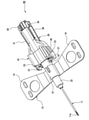
- FIG. 1 is a perspective view of the winged needle assembly 10
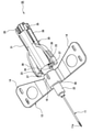
- FIG. 2 is an exploded perspective view of the winged needle assembly 10.
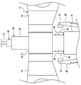
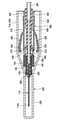
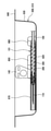
- FIG. 3 is a cross-sectional view of the winged needle assembly 10 cut along the axial direction of the housing 30 at the portion where the flexible piece 36 is formed.
- the winged needle assembly 10 includes a needle 11, a needle hub 20 to which a base end portion of the needle 11 is fixed, and a cylindrical housing 30 for accommodating the needle hub 20. Be prepared.
- the housing 30 supports the needle hub 12 at the first position where the needle 11 protrudes from the cylinder tip. Further, the housing 30 supports the needle hub 20 in a state where the needle 11 can slide from the first position to the second position in which the needle 11 is housed in the cylinder.
- the winged needle assembly 10 has a structure in which a needle hub 20 to which the needle 11 is fixed is interpolated so as to be movable in the axial direction with respect to the tubular housing 30. Further, the winged needle assembly 10 includes a spring 12 that urges the needle hub 20 to the base end side of the housing 30, and a wing 13 provided in the housing 30.
- the tube 100 is connected to the base end portion of the needle hub 20.
- the tip end side of the winged needle assembly 10 means the needle tip 11a side of the needle 11, and the proximal end side of the winged needle assembly 10 is the opposite side to the needle tip 11a and is a tube. It means the side to which a pipe such as 100 is connected.
- the direction in which the wing portion 14 of the wing 13 extends is referred to as a “left-right direction”
- the direction orthogonal to the left-right direction and the length direction (axial direction) of the needle 11 is referred to as a “vertical direction”.
- the winged needle assembly 10 includes an erroneous puncture prevention mechanism for accommodating the needle 11 in the housing 30 using a spring 12.
- the needle hub 20 is formed with a locking portion 23.
- the locking portion 23 is locked at the first position of the needle hub 20 in which the needle 11 protrudes from the tip of the housing 30 as a locked portion in which the locking portion 23 of the needle hub 20 is locked. It has a first opening 34 and a second opening 35 in which the locking portion 23 is locked at a second position of the needle hub 20 in which the needle 11 is housed in the housing 30. Further, it has a flexible piece 36 as an operation unit for pressing the locking portion 23.
- a spring 12 for urging the needle hub 20 toward the proximal end side is arranged in the housing 30.
- the winged needle assembly 10 is used in a state where the locking portion 23 of the needle hub 20 is fitted into the first opening 34 of the housing 30 and the needle 11 protrudes from the tip of the housing 30. After use, the locking portion 23 is fitted into the second opening 35, and the needle 11 is housed in the housing 30.
- the flexible piece 36 is pressed after use, the locking portion 23 fitted to the first opening 34 is pushed inside the housing 30 by the pressing protrusion 37 of the flexible piece 36 to push the first opening. It deviates from 34.
- the needle hub 20 slides toward the base end side by the urging force of the spring 12, the needle 11 is housed in the housing 30, and the locking portion 23 is fitted into the second opening 35 to fit the needle hub 20. The slide is locked.
- the needle 11 is, for example, a hollow needle made of metal such as stainless steel, has a sharp needle tip 11a so that it can be punctured, and is fixed to the tip of the needle hub 20. Has been done.
- the base end portion of the needle 11 is inserted into the inside of the needle hub 20 from the tip of the needle hub 20, and the hollow portion of the needle 11 communicates with the internal flow path of the needle hub 20.
- the length of the needle 11 is shorter than the axial length of the housing 30, and the entire needle 11 is housed in the cylinder of the housing 30 after use.
- the needle hub 20 is a cylindrical member to which the needle 11 is fixed, and is housed in the cylinder of the housing 30 in a state of being urged to the base end side of the housing 30 by the spring 12.
- the needle hub 20 is formed in a substantially cylindrical shape as a whole, and has a diameter that can be inserted into the cylinder of the housing 30.
- the needle hub 20 is made of, for example, a hard resin.
- a flow path for passing a drug solution or blood is formed in the cylinder of the needle hub 20, and as described above, this flow path communicates with the hollow portion of the needle 11.
- the internal flow path of the needle hub 20 is thin on the distal end side and thick on the proximal end side, and communicates with the hollow portion of the tube 100.
- a large diameter portion 21 having a large outer diameter is formed on the proximal end side of the central portion in the axial direction, and a small diameter portion 22 having a small outer diameter is formed on the tip end side.
- a pair of locking portions 23 are formed at the central portion in the axial direction of the needle hub 20.
- a pair of locking portions 23 extend from the outer peripheral surface at the boundary between the large diameter portion 21 and the small diameter portion 22.
- a flange portion 24 projecting in the radial direction is formed on the tip end side of the locking portion 23 of the needle hub 20.
- the flange portion 24 is an annular convex portion formed along the circumferential direction of the needle hub 20 (small diameter portion 22), and the spring 12 is in contact with the flange portion 24.
- the locking portion 23 may be a separate body from the tubular portion of the needle hub 20, or a separate locking portion may be attached to the tubular portion.
- a compression spring is used for the spring 12 that urges the needle hub 20 to the base end side of the housing 30.
- the spring 12 is, for example, a compression coil spring in which a metal wire is spirally wound, and presses the flange portion 24 of the needle hub 20 toward the proximal end side.
- the spring 12 is externally fitted from the tip of the needle hub 20 to the small diameter portion 22, and is arranged in the housing 30 in a state of being compressed by the annular portion 41 (see FIG. 3) formed at the flange portion 24 and the tip of the housing 30. Has been done.
- the needle hub 20 is formed with a ridge portion 25 extending from the flange portion 24 to the base end.
- the ridge portion 25 is a convex portion formed by partially projecting the outer peripheral surface of the needle hub 20 in the radial direction, and is formed along the axial direction of the needle hub 20.
- the ridges 25 are formed in pairs on the top and bottom of the needle hub 20, for example.
- a step 26 is formed in the ridge portion 25 at a portion sandwiched between the pair of locking portions 23, and the height of the ridge portion 25 is higher on the base end side than the step 26.
- a groove (not shown) is formed in which a portion of the convex portion 25 on the base end side of the step 26 is fitted.
- the concave-convex structure of the groove and the convex portion 25 guides the movement of the needle hub 20 along the axial direction of the housing 30, and the stepped portion of the convex portion 25 hits the tip of the groove to move toward the tip side. The movement of the needle hub 20 is restricted.
- the locking portion 23 is a portion that fits into the opening of the housing 30 and extends from the outer peripheral surface of the needle hub 20.
- One locking portion 23 is formed on each of the left and right sides of the needle hub 20, and the locking portion 23 extends from the central portion in the axial direction of the needle hub 20 toward the tip end. Further, the pair of locking portions 23 are inclined with respect to the axial direction of the needle hub 20 so that the distance between the locking portions 23 gradually increases from the root to the tip.
- Each tip of the pair of locking portions 23 is bent outward and protrudes to the left and right so that it can be easily caught in the opening of the housing 30. Further, the locking portion 23 is configured to be elastically deformed in the radial direction (left-right direction) of the needle hub 20. That is, the pair of locking portions 23 can be elastically deformed so that the distance between them changes. The locking portion 23 is arranged in the housing 30 in a state of being slightly compressed inward in the radial direction, for example.
- the housing 30 is a tubular member that accommodates the needle hub 20, and is formed in a substantially cylindrical shape as a whole.
- the tip of the needle hub 20 protrudes from the opening 33a on the tip side of the housing 30, and the base end of the needle hub 20 protrudes from the opening 33b on the base end side of the housing 30. That is, the length of the housing 30 is slightly shorter than the length of the needle hub 20.
- the housing 30 is made of, for example, a hard resin.
- the housing 30 has a substantially circular cross section at the tip end side portion and a substantially elliptical shape at the base end side portion having a major axis along the left-right direction.
- the base end side of the housing 30 is a large diameter portion 31 having a large outer diameter
- the tip end side is a small diameter portion 32 having a small outer diameter
- a pair of first openings 34, a pair of second openings 35, and a pair of flexible pieces 36 are formed on both the left and right sides of the large diameter portion 31.
- a protruding wall 40 is formed on the tip side of the first opening 34 as a malfunction suppressing portion for suppressing a malfunction of the erroneous puncture prevention mechanism due to an erroneous operation of the flexible piece 36.
- a wing 13 is mounted on the housing 30 on the tip side of the protruding wall 40.
- the wing 13 is, for example, a flexible rubber member used when performing a puncture operation, and is also used when fixing the winged needle assembly 10 to a patient's arm or the like using tape. Will be done.
- the wing 13 includes a pair of wing portions 14 extending in the left-right direction orthogonal to the axial direction of the housing 30, and a tubular portion 15 to which the roots of the wing portions 14 are connected, and the tubular portion 15 has a small diameter of the housing 30. It is attached to the housing 30 by being fitted externally to the portion 32.
- the wing portion 14 extends from the lower end portion of the tubular portion 15 to the left and right sides beyond the left and right ends of the flexible piece 36, and the tip is formed wider than the root.
- a ridge 39 extending from the protruding wall 40 toward the tip is formed at the upper end of the small diameter portion 32 of the housing 30, and a recess 16 into which the ridge 39 fits is formed at the upper end of the tubular portion 15 of the wing 13.
- the wing 13 is positioned in the circumferential direction with respect to the housing 30.
- the housing 30 has an annular portion 41 that protrudes toward the center of the opening 33a and is formed in an annular shape along the peripheral edge of the opening 33a.
- the spring 12 is arranged in a compressed state between the flange portion 24 and the annular portion 41 of the needle hub 20. As a result, an urging force that slides the needle hub 20 toward the base end side of the housing 30 can be obtained.
- the first opening 34 is formed at the tip of the large diameter portion 31 so as to penetrate the cylinder wall and one on each of the left and right sides.
- the first opening 34 is a locked portion to which the locking portion 23 of the needle hub 20 fits in the used state in which the needle 11 protrudes from the tip of the housing 30 (that is, the first position of the needle hub 20).
- the tip of the locking portion 23 is formed in a size that can be inserted.
- the tip of the locking portion 23 is hooked on the base end side edge portion of the first opening 34.
- the pair of first openings 34 are formed, for example, in a rectangular shape having the same size as each other.
- the cylinder wall of the housing 30 is a portion adjacent to the base end side of the first opening 34, and the inner diameter in the left-right direction is smaller than the distance between the pair of locking portions 23. In this case, since the pair of locking portions 23 are compressed inward in the radial direction, the needle hub 20 is stably fixed to the housing 30.
- the second opening 35 is formed at the base end portion of the large diameter portion 31 so as to penetrate the tubular wall and one on each of the left and right sides.
- the second opening 35 is a locked portion to which the locking portion 23 of the needle hub 20 fits in a state where the needle 11 is housed in the housing 30 (that is, the second position of the needle hub 20).
- the tip of the locking portion 23 is formed in a size that allows it to be inserted.
- the pair of second openings 35 are formed, for example, in a rectangular shape having the same size as each other, and the tip end portion of the locking portion 23 is hooked on the proximal end side edge portion of the second opening 35.
- the tubular wall of the housing 30 is formed with an inclined wall portion 38 inclined in the axial direction so as to gradually spread outward in the radial direction toward the base end side.
- the inclined wall portion 38 is formed on both the left and right sides from the central portion in the axial direction of the large diameter portion 31 to the edge portion of the second opening 35.
- the edge portion on the tip end side of the second opening 35 is located radially outside the edge portion on the proximal end side. In this case, when the needle hub 20 slides toward the proximal end due to the urging force of the spring 12, the locking portion 23 is more reliably guided to the second opening 35.
- the flexible piece 36 is an operation unit operated when the needle 11 is housed in the housing 30, and is formed in an arm shape extending from the outer peripheral surface of the large diameter portion 31.
- One flexible piece 36 is formed on each of the left and right sides of the housing 30, and extends from the axially central portion of the large diameter portion 31 toward the tip end. Further, the pair of flexible pieces 36 are inclined with respect to the axial direction of the housing 30 so that the distance between the flexible pieces 36 gradually increases from the root to the tip, and extend to a position facing the first opening 34.
- a spring may be provided between the flexible piece 36 and the outer peripheral surface of the housing 30 to hinder the displacement or pressing operation of the operating portion, but in this case, the configuration may be complicated or the suppressing function may be provided. Increasing the spring constant to increase it has the disadvantage of increasing the pressing force required for operation.
- the pair of flexible pieces 36 are configured to elastically deform in the radial direction (left-right direction) of the housing 30.
- a pressing protrusion 37 projecting in the direction of the first opening 34 is formed at the tip of each flexible piece 36.
- the pressing protrusion 37 is arranged to face the outside of the first opening 34 at a predetermined distance in the radial direction of the housing 30, and the needle hub that fits into the first opening 34 when the flexible piece 36 is pressed. Press the locking portion 23 of 20.
- the operation unit that presses the locking portion 23 is not limited to the flexible piece 36, and for example, a member that is separate from the cylinder portion of the housing 30 can be rotatably attached via a pin or the like to serve as an operation unit. good.
- the housing 30 is formed with a protruding wall 40 as a malfunction suppressing portion for suppressing a malfunction of the erroneous puncture prevention mechanism due to an erroneous operation of the flexible piece 36.
- the protruding wall 40 is a wall portion located between the wing 13 and the flexible piece 36 in the axial direction of the housing 30, in other words, between the wing 13 and the first opening 34, and intersects the axial direction of the housing 30. Overhanging in the direction.
- the protruding wall 40 is formed in a plate shape, and its thickness is reduced to the extent that deformation or breakage does not occur when pressed during a puncture operation or the like, for example, from the viewpoint of miniaturization of the instrument.
- the protruding wall 40 projects in the left-right direction in which a pair of flexible pieces 36 are lined up at a position close to the tip of the flexible piece 36 and not overlapping the flexible piece 36 in the left-right direction.
- the protruding wall 40 acts as a barrier during the puncture operation, and an unintended pressing operation of the flexible piece 36 is suppressed.
- the protruding wall 40 does not overlap with the flexible piece 36 in the left-right direction, it does not interfere with the intentional pressing operation of the flexible piece 36, and the good operability of the flexible piece 36 is as before. Secured.
- the protruding wall 40 is formed on the outer peripheral surface of the housing 30 between the wing 13 and the first opening 34, and projects beyond the tip of the locking portion 23 fitted to the first opening 34.
- the protruding wall 40 is formed adjacent to the wing 13 and the first opening 34 so as to separate them. Further, the protruding walls 40 are formed one on each of the left and right sides of the housing 30, and are formed to have the same length as each other.
- the pair of protruding walls 40 extend in parallel along the left-right direction (the direction in which the pair of flexible pieces 36 are lined up).
- the protruding wall 40 may extend diagonally in the left-right direction so as to gradually approach the flexible piece 36 toward the tip of the protruding wall 40 within a range that does not interfere with the flexible piece 36.
- the projecting wall 40 may extend diagonally in the left-right direction toward the tip of the projecting wall 40 so as to gradually move away from the flexible piece 36, as long as the malfunction of the flexible piece 36 can be suppressed. ..
- the protruding wall 40 may be a separate body from the tubular portion of the housing 30, or a separate protruding wall may be attached to the tubular portion.
- the protruding wall 40 overlaps the locking portion 23 in the axial direction of the housing 30 (see FIG. 3).
- the projecting wall 40 projects to the left and right so that the pressing projection 37 of the flexible piece 36 and the tip of the projecting wall 40 overlap each other in the axial direction of the housing 30.
- the length from the tip of one protruding wall 40 to the tip of the other protruding wall 40 along the left-right direction is larger than the major axis of the large diameter portion 31.
- the pair of protruding walls 40 may project to the left and right beyond the left and right ends of the flexible piece 36, but the tip position of the locking portion 23 may be set from the viewpoint of miniaturization of the instrument, operability at the time of puncturing, and the like. It is preferable that the flexible piece 36 is formed with a length that does not exceed the left and right ends.
- the protruding wall 40 projects only in the left-right direction from the outer peripheral surface of the housing 30, and does not substantially project in the vertical direction.
- the vertical length of the protruding wall 40 is, for example, the same as the vertical length of the large diameter portion 31.
- the tip edge of the protruding wall 40 may have a rounded curve with no corners, as the lower part may hit the patient's skin and the upper part may hit the fingertips of the user holding the winged needle assembly 10.
- the shape is preferable.
- the shape of the protruding wall is not limited to the shape of a thin plate.
- the width of the housing part where the protruding wall is located is wider on the left and right, and the ratio of the width to the height is larger. It is preferable to do so.
- FIGS. 4 and 5 are views showing a state in which the needle tip 11a is housed in the cylinder of the housing 30.
- the needle 11 can be accommodated in the housing 30 after use, and erroneous puncture by the needle 11 can be prevented.
- the pair of flexible pieces 36 are pressed while the needle 11 is punctured into the blood vessel of the patient after the treatment such as infusion or blood collection is completed, the pressing protrusion 37 of the flexible pieces 36 is inserted into the first opening 34.
- the tip of the locking portion 23 of the fitted needle hub 20 is pushed into the inside of the housing 30, the locking portion 23 is elastically deformed, and the tip of the locking portion 23 is disengaged from the first opening 34.
- the needle hub 20 Since the needle hub 20 is urged toward the proximal end side of the housing 30 by the spring 12, when the locking portion 23 is disengaged from the first opening 34, the needle hub 20 slides from the first position to the proximal end side.
- the needle 11 fixed to the tip of the needle hub 20 also slides toward the base end and is housed in the housing 30. Then, the locking portion 23 is restored and deformed in the process of moving to the proximal end side of the housing 30, and the tip end portion of the locking portion 23 enters the second opening 35 and is caught by the proximal end side edge portion of the second opening 35. ..
- the slide By fitting the tip of the locking portion 23 into the second opening 35, the slide is locked so that the needle hub 20 does not move from the second position, and the needle 11 is prevented from re-protruding. As a result, the winged needle assembly 10 can be safely disposed of.
- FIG. 6 is a diagram showing a state of puncture operation using the winged needle assembly 10 having the above configuration.
- the wing portion 14 is gripped in a state where the pair of wing portions 14 are bent upward and overlapped with each other. That is, the pair of wing portions 14 are bent upward so as to sandwich the tubular portion 15 of the wing 13 and gripped, and the needle 11 is punctured into the blood vessel of the patient.
- the protruding wall 40 projects greatly from a position close to the tip of the flexible piece 36, the protruding wall 40 serves as a barrier and erroneous operation of the flexible piece 36 is effectively suppressed. Therefore, according to the winged needle assembly 10, it is possible to suppress the malfunction of the erroneous puncture prevention mechanism due to the erroneous operation of the flexible piece 36.
- the indwelling needle with a wing is required to be small, so that the housing is difficult to lengthen in the axial direction, and as a result, the place where the spring is pressed is the housing.
- the flexible piece 36 is likely to be erroneously operated when gripping the wing.
- by forming the protruding wall 40 it is possible to make it difficult to erroneously operate the flexible piece 36 when gripping the wing, and it is possible to suppress the malfunction of the erroneous puncture prevention mechanism while reducing the size. Can be done.
- FIG. 7 is a perspective view of the winged needle assembly 50
- FIG. 8 is a plan view of the winged needle assembly 50, which is an enlarged view of the malfunction suppressing member 51 and its vicinity.
- the same reference numerals will be used for the same or similar components as those in the first embodiment, and duplicate description will be omitted.
- the winged needle assembly 50 includes a needle 11, a needle hub 20, and a housing 30, similar to the winged needle assembly 10. Further, the winged needle assembly 50 includes a spring 12 (not shown in FIGS. 7 and 8) and a wing 13.
- the protruding wall 40 does not exist in the housing 30, and the malfunction suppressing member 51 for suppressing the malfunction of the erroneous puncture prevention mechanism due to the erroneous operation of the flexible piece 36 is the cylinder of the wing 13. It differs from the winged needle assembly 10 in that it is provided in the portion 15.
- the malfunction suppressing member 51 is provided on the wing 13 and is an obstructing portion that prevents the wing portion 14 from bending inside the housing 30 in the radial direction of the locking portion 23, and is detachably attached to the tubular portion 15. It may be bonded, or it may be joined using an adhesive or the like.
- the malfunction suppressing member 51 is a semi-cylindrical member that curves along the outer peripheral surface of the tubular portion 15 and covers the upper portion and the left and right sides of the tubular portion 15. As shown in FIG. 6, the wing portion 14 is gripped during the puncture operation, but according to the winged needle assembly 50, the malfunction suppressing member 51 is attached to the tubular portion 15 to move the root portion of the wing portion 14 to the left and right. By making the thickness thicker, the thick root portion becomes an obstacle and the erroneous operation of the flexible piece 36 is suppressed.
- the root portion of the wing 13 including the tubular portion 15 and the malfunction suppressing member 51 that is, the portion surrounding the outer peripheral surface of the small diameter portion 32 of the housing 30, is formed with thicker left and right side portions than the lower portion.
- the semi-cylindrical malfunction suppressing member 51 having a substantially constant thickness is attached to the portion of the tubular portion 15 located above the wing portion 14, other than the lower portion of the root portion of the wing 13. Is formed thick. If the thickness of the lower part of the root portion that forms the lower surface of the wing 13 together with the wing portion 14 is increased, the punctured needle 11 imposes a burden on the blood vessel, so that the left and right side portions are thickened without increasing the thickness of the lower portion. By doing so, it is possible to effectively suppress the erroneous operation of the flexible piece 36 while preventing such a problem.
- the malfunction suppressing member 51 projects to the left and right at least to a position where the tip of the locking portion 23 fitted to the first opening 34 overlaps with the axial direction of the housing 30 in a state of being attached to the tubular portion 15. (See FIG. 8).
- the left and right ends of the malfunction suppressing member 51 and the tips of the pair of locking portions 23 are aligned in the axial direction of the housing 30.
- the wing portion 14 is gripped in a state where the pair of wing portions 14 are bent upward and overlapped with each other, so that the root portion of the wing portion 14 becomes thicker by the thickness thereof, and the tip of the locking portion 23 is pressed. It overhangs to the left and right.
- the malfunction suppressing member 51 may be formed to have the same length as the tubular portion 15 as long as it does not interfere with the flexible piece 36.
- the malfunction suppressing member 51 may be formed with protrusions (wall portions) protruding to the left and right like the stopper 61 described later, and the malfunction suppressing member 51 may be formed with a pressing protrusion 37 in the axial direction of the housing 30. It may extend to the left and right to the overlapping position.
- FIG. 9 is a perspective view of the winged needle assembly 55, which is a modification of the winged needle assembly 50.
- the winged needle assembly 55 is common to the winged needle assembly 50 in that a malfunction suppressing portion is provided in the wing 13.
- the winged needle assembly 55 is different from the winged needle assembly 50 in that the tubular portion and the malfunction suppressing portion are integrated. That is, the winged needle assembly 55 is provided with a malfunction suppressing cylinder portion 56 that projects to the left and right to at least a position where the tip of the locking portion 23 fitted to the first opening 34 and the housing 30 overlap in the axial direction. There is.
- the malfunction suppressing cylinder portion 56 is formed with a recess 16 into which the convex portion 39 of the housing 30 fits.
- the malfunction suppressing cylinder portion 56 which is the root portion of the wing 13, is formed with a thicker upper portion and left and right side portions than the lower portion, and the upper end of the tubular portion projects above the outer peripheral surface of the large diameter portion 31 of the housing 30. ing. Further, the malfunction suppressing cylinder portion 56 may project to the left or right from the outer peripheral surface of the large diameter portion 31.
- the winged needle assembly 55 similarly to the winged needle assembly 50, the root portion of the thick wing portion 14 becomes an obstacle and erroneous operation of the flexible piece 36 during the puncture operation is suppressed.
- the wing portion 14 may be provided with an obstructing portion that prevents the wing portion 14 from bending in the radial direction of the housing 30 with respect to the locking portion 23.
- the obstruction portion is, for example, a plate-shaped member attached to the upper surface of the wing portion 14, and increases the thickness in the vicinity of the root of the wing portion 14 to increase the rigidity.
- the thickness may be thin as long as the member has high rigidity.
- the vicinity of the root of the wing portion 14 may be formed thickly to increase the rigidity.
- FIGS. 10 to 12 are perspective views of the winged needle assembly 60
- FIG. 11 is a perspective view of the stopper 61.
- the same reference numerals will be used for the same or similar components as those in the first and second embodiments, and duplicate description will be omitted.
- the winged needle assembly 60 includes a needle 11, a needle hub 20, and a housing 30, similar to the winged needle assemblies 10 and 50. Further, the winged needle assembly 60 includes a spring 12 (not shown in FIG. 10) and a wing 13. On the other hand, the winged needle assembly 60 differs from the winged needle assembly 10 and 50 in that it includes a stopper 61 that is movable or detachably attached to the outer peripheral surface of the housing 30 as a malfunction suppressing portion. ..
- the stopper 61 is an obstruction portion that hinders the displacement or pressing operation of the flexible piece 36 which is an operation portion, is detachably attached to the outer peripheral surface of the housing 30, and is between the outer peripheral surface and the flexible piece 36. It is intervening. That is, the stopper 61 is attached to the portion of the outer peripheral surface of the housing 30 located inside the flexible piece 36. In this case, during the puncture operation, the stopper 61 becomes an obstacle to restrict the inward movement of the flexible piece 36, and the contact between the pressing protrusion 37 and the locking portion 23 is prevented. Therefore, even if the flexible piece 36 is accidentally pressed, the malfunction of the erroneous puncture prevention mechanism does not occur. Further, by removing the stopper 61, the flexible piece 36 can be pressed as in the conventional case.
- the stopper 61 is curved along the outer peripheral surface of the housing 30, and has a semi-cylindrical base 62 that covers the upper portion and both left and right sides of the housing 30, and a semi-cylindrical base 62 that covers both left and right sides from the base 62, respectively. It has a pair of protruding protrusions 63.
- the base portion 62 is externally fitted to the large diameter portion 31 of the housing 30.
- the protrusion 63 is formed at a position where it overlaps the flexible piece 36 in the left-right direction. Further, the protrusion 63 has a substantially triangular shape in which the protrusion length gradually increases toward the tip end side of the flexible piece 36.
- the protrusion 63 is formed to have a length in which the locking portion 23 is not pressed by the pressing protrusion 37 when the flexible piece 36 is pressed.
- the stopper 61 has a pair of gripping portions 64 extending upward from both the left and right sides of the base portion 62.
- the grip portion 64 is formed over the entire length of the base portion 62, and is slightly curved so that the tip is located slightly outside the root. By picking the pair of grips 64 from the outside and pressing them inward, the lower end side of the base 62 can be widened, and the stopper 61 can be easily removed from the housing 30.
- the base portion 62 is configured to be elastically deformable in the left-right direction, has an inner diameter slightly smaller than the outer diameter of the large diameter portion 31, and is attached in a state where the outer peripheral surface of the large diameter portion 31 is pressed. .. Since the stopper 61 is easily deformed, it is not arranged between the locking portion 23 and the pressing protrusion 37. The stopper does not have to have a pair of grip portions 64, and may be removable without pinching the grip portions 64 from the outside.
- FIG. 12 is a perspective view of the winged needle assembly 65, which is a modification of the winged needle assembly 60.
- the winged needle assembly 65 is common with the winged needle assembly 60 in that it includes a stopper 66 attached to the outer peripheral surface of the housing 30x as a malfunction suppressing portion.
- the winged needle assembly 65 is configured so that the stopper 66 does not need to be removed even when the needle 11 is housed in the housing 30x by pressing the flexible piece 36. Different from assembly 60.
- the stopper 66 has a semi-cylindrical base portion 67 that is externally fitted to the large diameter portion 31x of the housing 30x, and a grip portion 68 that extends from the base portion 67.
- the base portion 67 is configured to be elastically deformable in the left-right direction, has an inner diameter slightly smaller than the outer diameter of the large diameter portion 31, and is attached in a state where the outer peripheral surface of the large diameter portion 31 is pressed.
- the grip portion 68 extends upward from the upper end of the base portion 67.
- the stopper 66 does not have protrusions protruding to the left and right, and in the example shown in FIG. 12, the stopper 66 is locked to the portion of the outer peripheral surface of the housing 30x located inside the flexible piece 36 so as to be fitted to the first opening 34.
- a stopper 66 is attached so as to cover the portion 23.
- a recess 69 in which the stopper 66 is housed is formed on the outer peripheral surface of the housing 30x.
- the recess 69 is a portion of the outer peripheral surface of the large diameter portion 31x located inside the flexible piece 36, and is formed on the proximal end side of the first opening 34.
- the recesses 69 are formed, for example, by cutting out the left and right side portions of the cylinder wall of the large diameter portion 31x so that the base portion 67 of the stopper 66 fits into the recesses 69, one on each side.
- the recess 69 is formed at a depth corresponding to the thickness of the base 67.
- a pressing force acts on the outer peripheral surface of the large diameter portion 31.
- a second recess shallower than the recess 69 may be formed in the large diameter portion 31x so that the stopper 66 does not move from the initial mounting position, and a lock mechanism for fixing the stopper 66 after movement is provided. It may be provided. Further, the axial length of the stopper 66 may be shortened so that the tip end side of the flexible piece 36 can be pressed even if the stopper 66 does not bend inward.
- the stopper 66 is moved to the recess 69 so that the stopper 66 is not removed from the housing 30x.
- the flexible piece 36 can be pressed. Therefore, it is not necessary to remove the stopper 66 and dispose of it separately as dust, which improves user convenience.
- each of the above embodiments can be appropriately redesigned as long as the object of the present invention is not impaired.
- the malfunction suppressing portion of the above embodiment is provided on both the left and right sides, it may be provided on only one of the left and right sides.
- the malfunction suppressing portion may be a wall portion that covers a part of the operating portion.
- the wall portion overlaps a part of the operation unit in the vertical direction, but does not overlap the operation unit in the left-right direction. Therefore, the intentional pressing operation of the operating portion can be easily performed while avoiding the wall portion.
- the wall portion that functions as the malfunction suppressing portion only needs to be able to reduce the situation where the locked portion is unlocked from the locked portion, and the wall portion extends until it covers the upper part of the pressing protrusion 37 of the flexible piece 36. It doesn't have to be.
- the wall portion is not limited to the wall protruding in the axial direction of the housing, and may be a wall extending between the operation portion and the locking portion along the axial direction, and the wall portion is made of a member constituting the wing. It may be extended. For example, a wall portion extending from the cylinder portion in the proximal direction may be provided. With the wall portion, even if the operation portion unintentionally hits the finger when gripping the wing, the finger can hit the wall portion before the locking portion is unlocked, and the user can use the wall portion. By calling attention, it is possible to reduce unintended unlocking of the locking portion.
- the malfunction suppressing portion is formed in the tubular portion located at the center of the pair of wings, but may be formed only in the wing portion. Further, a protrusion extending radially outward from the outer surface of the cylinder portion may be provided, and the bending of the wing may be restricted by the protrusion. For example, it is possible to provide a protruding portion extending in the left-right direction from the top surface of the cylinder portion, or to adopt a shape in which the width of the cylinder portion increases in the left-right direction from the top surface toward the bottom surface.
- the wing may be made of different materials by two-color molding, etc., a plurality of convex portions may be provided linearly, or a linear rib may be provided so that the inflection point of the bending of the wing is set to a desired position. You can also.
- a stopper having a semi-cylindrical base attached to the outer peripheral surface of the housing 30 is exemplified, but the obstruction portion covers the entire operation portion. It may be a movable or removable cap body to cover.
- the obstructing portion may be a completely tubular body as long as it covers the operating portion. Alternatively, it may be a movable or removable cap body that covers a part of the operating portion (for example, the pressing protrusion 37 of the flexible piece 36). Further, it may be a movable or removable cap body that covers the locking portion.
- the operating portion may extend from the vicinity of the wing 13 to the proximal end side, and as shown in Japanese Patent Application Laid-Open No. 2011-200599, the operating portion and the locked portion are provided on the upper surface of the housing, not on the left and right. It may have been.
- a protruding wall may be arranged on the upper surface of the housing located between the locked portion and the wing.
- the direction in which the operation unit extends is not particularly limited, and the number and shape thereof are not limited to the above-described embodiment.
- the housing is locked when the locking portion is locked at the first position of the needle hub where the needle protrudes from the tip of the cylinder and is pressed. It may have an operation unit from which the unit can be removed. That is, the operating portion also functions as a locked portion. Also in this case, the above-mentioned malfunction suppressing portion can be applied, and the unintended pressing of the operating portion can be effectively suppressed. Further, as shown in Japanese Patent Publication No. 2007-521080 (FIG. 14), the housing has a locked portion in which the locking portion is locked at the first position of the needle hub, and has an operating portion. It may not be configured. Also in this case, the above-mentioned malfunction suppressing portion can be applied, and the unintended pressing of the locking portion can be effectively suppressed.
- FIGS. 13 to 18 The winged needle assembly set 1 according to the first embodiment will be described in detail with reference to FIGS. 13 to 18.
- 13 is a perspective view of the winged needle assembly set 1
- FIG. 14 is an exploded perspective view of the winged needle assembly set 1
- FIG. 15 is a cross-sectional view of the winged needle assembly set 1.
- the winged needle assembly set 1 includes a winged needle assembly 101 and a case 500 mounted on the winged needle assembly 101.
- the winged needle assembly 101 has a needle 110 having a blade surface at the tip thereof, a cylindrical main body to which the needle 110 is fixed, and a pair of wing portions 140 provided on the main body.
- the main body of the winged needle assembly 101 is composed of a needle hub 200 to which the base end portion of the needle 110 is fixed, and a cylindrical housing 300 that supports the needle hub 200.
- the pair of wing portions 140 is composed of a member separate from the housing 300 and is attached to the tip portion of the housing 300.
- the tube 100 (see FIG. 15) is connected to the base end portion of the needle hub 200.
- the tip end side of the winged needle assembly 101 means the needle tip 110a side of the needle 110
- the proximal end side of the winged needle assembly 101 is the opposite side to the needle tip 110a and is a tube. It means the side to which a pipe such as 100 is connected.
- the direction in which the wing portion 140 extends is referred to as a “left-right direction”
- the direction orthogonal to the left-right direction and the length direction (axial direction) of the needle 110 is referred to as a “vertical direction”.
- the terms indicating the directions such as up / down and left / right are also used for the case 500 in the same manner.
- the case 500 is a cap body used for the winged needle assembly 101, and is removed when puncturing is performed.
- the case 500 is a kind of packaging material for covering the winged needle assembly 101, and is attached to the winged needle assembly 101 in a storage state until puncture is performed.
- the case 500 is formed in a cylindrical shape that can accommodate the winged needle assembly 101 as a whole, and is mounted so as to cover most of the winged needle assembly 101 from the needle tip 110a to the base end of the housing 300. Has been done.
- the pair of wing portions 140 extend to the outside of the case 500, and most of them are not covered by the case 500 except for the vicinity of the root.
- the case 500 is configured to be in contact with the pair of wing portions 140 so that the pair of wing portions 140 are erected in the same direction.
- the winged needle assembly set 1 has a structure in which the winged needle assembly 101 is inserted into the cylinder of the case 500, and the pair of wing portions 140 greatly project outside the case 500.
- the pair of wing portions 140 stand up substantially parallel to each other from the upper end of the case 500 upward.
- the base end of the case 500 is open, and the winged needle assembly 101 is inserted through this opening.
- the pair of wing portions 140 are bent upward and gripped, but according to the winged needle assembly set 1, this state is already formed by the case 500, so that when performing the puncture operation. It is possible to grip the pair of blades 140 stably and quickly.
- winged needle assembly 101 and the case 500 constituting the winged needle assembly set 1 will be described in detail with reference to FIGS. 16 and 17 as appropriate.
- FIG. 16 is a perspective view of the winged needle assembly 101.
- the winged needle assembly 101 includes a needle 110, a needle hub 200 to which the base end portion of the needle 110 is fixed, and a cylindrical housing 300 into which the needle hub 200 is inserted.
- the housing 300 supports the needle hub 200 in a state where the needle 110 can slide from the first position where the needle 110 protrudes from the tip of the cylinder to the second position where the needle 110 is housed in the cylinder.
- the winged needle assembly 101 has the same structure as the winged needle assembly 10 except that it does not have a protruding wall 40 which is a malfunction suppressing portion. Therefore, the configuration of the winged needle assembly 101 will be briefly described below.
- the winged needle assembly 101 is further located on the tip side of the needle hub 200, and is in a compressed state and has a spring 120 and a spring that generate an urging force to move the needle hub 200 to the base end side of the housing 300. It has an operation unit for releasing the compression of the 120, and is provided with an erroneous puncture prevention mechanism for accommodating the needle 110 in the housing 300 by using the spring 120 and the operation unit.
- the housing 300 accommodates the needle 110 after decompression of the spring 120.
- the needle hub 200 is formed with a locking portion 230
- the housing 300 has a first opening 340 in which the locking portion 230 is locked at the first position of the needle hub 200, and the needle hub 200.
- a second opening 350 is formed in which the locking portion 230 is locked at the second position.
- the housing 300 has a flexible piece 360 as the operation unit.
- a large diameter portion 210 having a large outer diameter is formed on the base end side of the central portion in the axial direction, and a small diameter portion 220 having a small outer diameter is formed on the tip end side.
- a pair of engaging portions 230 extend from the boundary portion between the large diameter portion 210 and the small diameter portion 220, and the flange portion 240 is formed on the tip end side of the locking portion 230.
- the spring 120 is fitted onto the small diameter portion 220 from the tip of the needle hub 200, and is compressed by the annular portion 390 (see FIG. 15) formed at the flange portion 240 and the tip of the housing 300. It is arranged within 300.
- the housing 300 is made of, for example, a hard resin, and the cross section of the proximal end side portion has a substantially elliptical shape having a major diameter along the left-right direction, the cross section of the distal end side portion has a substantially perfect circular shape, and the proximal end side is an outer portion.
- the large diameter portion 310 having a large diameter and the small diameter portion 32 having a small outer diameter on the tip side.
- a pair of first openings 340, a pair of second openings 350, and a pair of flexible pieces 360 are formed on both the left and right sides of the large diameter portion 310.
- a pressing protrusion 370 protruding in the direction of the first opening 340 is formed at the tip of each flexible piece 360.
- the housing 300 is provided with a pair of wing portions 140.
- the wing portion 140 is used when fixing the winged needle assembly 101 to the patient's arm or the like using a tape after the puncture of the needle 110, and is also used when puncturing.
- the wing portion 140 is made of, for example, a flexible resin and is attached to the tip portion of the housing 300.
- the pair of wing portions 140 extend from the tip end portion of the housing 300 to the left and right beyond the left and right ends of the flexible piece 360.
- the wing portion 140 has a shape in which the tip is formed wider than the root, but the shape of the wing portion 140 is not particularly limited.
- a tubular portion 150 is provided at the base of the pair of wing portions 140, and the pair of wing portions 140 is attached to the housing 300 by externally fitting the tubular portion 150 to the small diameter portion 320 of the housing 300. That is, the pair of wing portions 140 are connected via the tubular portion 150 and are attached to the small diameter portion 320.
- a ridge portion 380 extending toward the tip side is formed at the upper end portion of the small diameter portion 320, and a recess 160 into which the ridge portion 380 fits is formed at the upper end portion of the tubular portion 150. Due to this uneven structure, the wing portion 140 is positioned in the circumferential direction with respect to the housing 300.
- the pair of wing portions 140 are connected to the lower end portion of the tubular portion 150 and extend to the left and right from the lower portion of the small diameter portion 320. Since the pair of wing portions 140 have flexibility, the root portion can be bent so that the tip faces upward, and as shown in FIG. 18 described later, the pair of wing portions 140 is bent upward when puncturing. The pair of wing portions 140 are overlapped and gripped. Further, since the wing portion 140 is elastically deformed, it returns to the original shape that spreads to the left and right when the hands are released.
- FIG. 17 is a perspective view of the case 500.
- the case 500 has a first tubular portion 510 as a base that abuts on the pair of wing portions 140 and erects the pair of wing portions 140 in the same direction.
- the case 500 has a second cylinder portion 520 extending from the tip of the first cylinder portion 510.
- the second cylinder portion 520 is a cap portion for accommodating the needle 110.
- the case 500 is, for example, an integrally molded product made of a hard resin, and the internal spaces of the first cylinder portion 510 and the second cylinder portion 520 communicate with each other.
- the case 500 has a shape corresponding to the shape of the winged needle assembly 101, and the first cylinder portion 510 is formed larger to the left and right than the second cylinder portion 520.
- the second tubular portion 520 is formed in a cylindrical shape having a perfect circular cross section orthogonal to the length direction, and has a substantially constant diameter.
- the first cylinder portion 510 is formed in a square cylinder shape that is longer in the left-right direction than in the vertical direction, and the length in the left-right direction (hereinafter, may be referred to as “width”) is on the tip side close to the second cylinder portion 520. It's getting shorter.
- the vertical length of the first cylinder portion 510 is equal to or slightly longer than the vertical length of the second cylinder portion 520.
- the second cylinder portion 520 has a bottomed cylindrical shape with a closed tip, and accommodates and protects the entire needle 110. As shown in FIG. 15, the inner diameter of the second cylinder portion 520 is larger than the outer diameter of the small diameter portion 320 of the housing 300, and the tip end portion of the small diameter portion 320 may be inserted into the second cylinder portion 520. In the present embodiment, the small diameter portion 320 is inserted into the second cylinder portion 520 in a state where the outer peripheral surface of the small diameter portion 320 is in contact with the inner peripheral surface of the second cylinder portion 520. As a result, the movement of the winged needle assembly 101 in the case 500 in the vertical and horizontal directions is restricted, and the case 500 is stably mounted on the winged needle assembly 101.
- the engaging portion between the case 500 and the winged needle assembly 101 is not limited to the small diameter portion 320, and may be formed at another portion.
- the tip of the needle hub may be engaged with the case 500.
- the winged needle assembly may be engaged with the peripheral portion of the lower cover portion 540 or the upper opening 560, which will be described later. It is preferable that the engaging portion between the case 500 and the winged needle assembly 101 is formed on the tip side of the wing portion because it can be stably disengaged when the case is removed.
- the case 500 houses most of the winged needle assembly 101 excluding the pair of wing portions 140 from the needle tip 110a to the base end of the housing 300 in the cylinder.
- the length of the case 500 is, for example, equal to or slightly longer than the length of the winged needle assembly 101.
- the second cylinder portion 520 is formed with a length such that the needle tip 110a does not touch the inner surface of the bottom portion in a state where the tip portion of the housing 300 is inserted into the cylinder. If the needle tip 110a does not protrude from the second cylinder portion 520, the tip of the second cylinder portion 520 may be open.
- the length of the case 500 may be shorter than that of the winged needle assembly 101, and most of the base end side of the housing 300 may protrude from the case 500, but the operation part such as the pair of flexible pieces 360 may be the case. It is preferably covered with 500. Since the winged needle assembly 101 has an erroneous puncture prevention function, by covering the flexible piece 360 with the case 500, the flexible piece 360 is erroneously pressed during a puncture operation or the like, and the erroneous puncture prevention mechanism is erroneous. It can be effectively prevented from operating.
- the first cylinder portion 510 is a portion for erecting the pair of wing portions 140, and accommodates the root portion of the pair of wing portions 140 and most of the housing 300 including the flexible piece 360, and the second cylinder portion 520. It overhangs to the left and right beyond the left and right ends of.
- the width of the first tubular portion 510 is smaller on the distal end side than on the proximal end side, and the narrowed width portion 510a is formed on the distal end side of the first tubular portion 510.
- the width of the narrowed portion 510a gradually decreases toward the tip of the first cylinder portion 510, but even if the first cylinder portion 510 is formed with a step that sharply changes the width. good.
- the first cylinder portion 510 is formed with a wide portion 510b having a width larger than that of the narrowed portion 510a from the portion corresponding to the tip portion of the flexible piece 360 to the base end. As shown in FIG. 15, the boundary between the narrowed portion 510a and the wide portion 510b exists at a position where it overlaps with each tip portion of the pair of flexible pieces 360 in the left-right direction. In the wide portion 510b, the distance (W1) between the inner surfaces facing each other in the left-right direction is larger than the length (W2) along the left-right direction extending from the left end of the left flexible piece 360 to the right end of the right flexible piece 360. The first tubular portion 510 is formed so as not to come into contact with the flexible piece 360.
- the first cylinder portion 510 includes a pair of side wall portions 530 that cover the sides of the housing 300, a lower cover portion 540 that covers the lower part of the housing 300, and an upper cover portion 550 that covers the upper part of the housing 300.
- the pair of side wall portions 530 are formed diagonally with respect to the axial direction of the first tubular portion 510 in the narrowed portion 510a, and are formed parallel to the axial direction of the first tubular portion 510 in the wide portion 510b.
- the pair of side wall portions 530 are arranged to face each other from the base end of the first tubular portion 510 to the position corresponding to the tip end portion of the flexible piece 360 with a distance (W1) larger than the above length (W2). ..
- the lower cover portion 540 is formed along the left-right direction so as to connect the lower ends of the pair of side wall portions 530, and widely covers the lower surface of the housing 300. By providing the lower cover portion 540, the lower portion of the housing 300 is protected, and by connecting the pair of side wall portions 530, the mechanical strength of the case 500 is improved. Further, the lower cover portion 540 may be formed with a recess 540a in which the large diameter portion 310 of the housing 300 is fitted along the axial direction of the first cylinder portion 510. The recess 540a functions as a guide when mounting the case 500 on the winged needle assembly 101, for example.
- the upper cover portion 550 extends inward in the left-right direction from the upper ends of the pair of side wall portions 530, and is formed substantially parallel to the lower cover portion 540.
- the upper cover portion 550 covers the upper part of the flexible piece 360 of the housing 300, but does not substantially cover the upper surface of the large diameter portion 310. That is, the upper surface of the large diameter portion 310 is not covered by the case 500 and is largely exposed.
- the first tubular portion 510 is formed with an upper opening 560 that exposes the upper surface of the large diameter portion 310. By forming the upper opening 560, the case 500 can be mounted on the winged needle assembly 101 with the pair of wing portions 140 standing upright.
- the upper opening 560 is formed in a substantially rectangular shape in a plan view from the base end of the first cylinder portion 510 to the vicinity of the second cylinder portion 520 along the axial direction of the case 500. Further, the upper opening 560 is formed, for example, with a width slightly larger than the width of the tubular portion 150 to which the pair of wing portions 140 are connected. Since the pair of wing portions 140 are bent at the root (connecting portion with the tubular portion 150), in this case, the pair of wing portions 140 that are bent upward and stand up can easily extend straight from the upper opening 560.
- a pair of upper cover portions 550 are formed on both the left and right sides of the upper opening 560 with the same width.
- a pair of upright wing portions 140 are in contact with the tip edge portion 560a of the upper opening 560. This restricts the movement of the winged needle assembly 101 toward the tip of the case 500.
- the upper opening 560 is formed, for example, with a length at which the tip portion of the housing 300 is inserted into the second cylinder portion 520 when the wing portion 140 abuts on the tip edge portion 560a.
- the side edge portion 560b (inner end edge of the upper cover portion 550) of the upper opening 560 is formed linearly along the axial direction of the case 500, and is a surface of a pair of standing wing portions 140 facing outward in the left-right direction. Is in contact with. That is, the pair of upright wing portions 140 are supported from the outside by the side edge portion 560b, and the upright state of the wing portions 140 is maintained.
- the first cylinder portion 510 is formed with a tongue piece portion 570 extending from the tip edge portion 560a of the upper opening 560 toward the proximal end side.
- the tongue piece portion 570 may extend so as to cover the upper part of the tubular portion 150 and may be in contact with the upper surface of the tubular portion 150.
- the tubular portion 150 of the housing 300 is pressed from above by the tongue piece portion 570, and for example, the case 500 is firmly and stably mounted.
- the vertical distance between the tongue piece portion 570 and the lower cover portion 540 is equal to or slightly smaller than the vertical length of the tubular portion 150.
- a groove 580 through which the upright wing portion 140 can be inserted is formed between the tongue piece portion 570 and the side edge portion 560b.
- Grooves 580 are formed on both the left and right sides of the tongue piece portion 570, and the pair of wing portions 140 are arranged so as to sandwich the tongue piece portion 570.
- the pair of wing portions 140 stand upward with the vicinity of the root sandwiched between the side edge portion 560b and the tongue piece portion 570.
- the first tubular portion 510 is based on the upper opening 560, which is an opening for extending the pair of blade portions 140 to the outside of the case 150, and the tip edge portion 560a, which is the edge of the upper opening 560. It has a tongue piece portion 570 that extends to the end side and presses the tubular portion 150 of the winged needle assembly 101. Further, the first tubular portion 510 is formed between the side edge portion 560b of the upper opening 560 and the tongue piece portion 570, and has a groove 580 through which the pair of wing portions 140 are inserted.
- the tongue piece portion 570 is formed, for example, with a length that covers the tubular portion 150.
- the tongue piece portion 570 is lengthened, it becomes easier to prevent the case 500 from coming off, but if it is too long, the tip of the needle 110 comes into contact with the tongue piece portion 570 when the winged needle assembly 101 is pulled out from the case 500. It may cause problems such as damage. Further, in order to prevent the upper opening 560 from bending, the edge of the upper opening 560 may have a thick wall shape, and walls along the vertical direction may be formed on the tip edge portion 560a and the side edge portion 560b.
- FIG. 18 is a diagram showing a state of a puncture operation using the winged needle assembly 101.
- the pair of wing portions 140 are bent upward and gripped in a superposed state. That is, the pair of wing portions 140 are bent upward and gripped so as to sandwich the tubular portion 150.
- the winged needle assembly set 1 having the above configuration, the pair of wing portions 140 extend out of the case 500 in a state of standing upward, so that the medical staff can be stable and prompt.
- the wing portion 140 can be gripped. That is, the case 500 realizes a state in which the wing portion 140 is erected in the same direction.
- the second cylinder portion 520 for accommodating the needle 110 since the first cylinder portion 510 for raising the wing portion 140 and the second cylinder portion 520 for accommodating the needle 110 are integrated, the second cylinder portion is held after the pair of wing portions 140 are stably gripped.
- the case 500 can be removed by pulling the portion 520 toward the tip side.
- the case 500 covers substantially the entire winged needle assembly 101 excluding the wing portion 140, there is no place to grip other than the wing portion 140, and this procedure can be performed more reliably.
- the winged needle assembly set 1 in addition to the pair of wing portions 140 standing upward, the pair of flexible pieces 360 are covered with the case 500, so that the flexible piece 360
- the wing portion 140 is gripped in a state where it is difficult to be erroneously pressed.
- the wing portion 140 or a finger hits the flexible piece 360, the flexible piece 360 is erroneously pressed, and the erroneous puncture prevention mechanism may malfunction.
- the case 500 prevents the flexible piece 360 from being pressed even during transportation and storage.
- FIG. 19 is a perspective view of the winged needle assembly set 2
- FIG. 20 is a cross-sectional view of the winged needle assembly set 2.
- the same reference numerals will be used for the same or similar components as those in the first embodiment, and duplicate description will be omitted.
- the winged needle assembly set 2 includes a case 600 as a packaging material for covering the winged needle assembly 101.
- the case 600 is erected on the case main body 610 for accommodating the winged needle assembly 101 and the bottom portion 620 of the case main body 610, abuts on the pair of wing portions 140, and the pair of wing portions 140 stand up in the same direction. It also has a pair of first holding portions 650 for sandwiching the winged needle assembly 101.
- the case 600 may be provided with a pair of second holding portions 660 for sandwiching the base end portion of the housing 300.
- the second holding portion 660 is erected on the bottom portion 620 of the case main body 610, similarly to the first holding portion 650.
- the cap 670 described later is used as a cap for accommodating the needle 110, the case 600 does not have a configuration like the tongue piece portion 570 described above.
- the case body 610 has a container shape with an open upper part, and houses the entire winged needle assembly 101.
- the case body 610 has a bottom portion 620 having a substantially rectangular shape in a plan view, a side portion 630 standing on the peripheral edge portion of the bottom portion 620, and a flange portion 640 protruding outward in parallel with the bottom portion 620 from the upper end of the side portion 630. ..
- the bottom portion 620 is formed flat except for the portion where the holding portion is formed, and is formed in a size capable of mounting the winged needle assembly 101.
- the side portion 630 is formed in a square cylinder shape and surrounds the four sides of the winged needle assembly 101. Further, the side portion 630 is formed at a height at which a pair of upright wing portions 140 do not protrude from the opening of the case body 610. That is, the bottom portion 620 and the side portions 630 form a space separated from the surroundings that can accommodate the entire winged needle assembly 101. For example, a sheet for sealing the opening of the case body 610 may be attached to the flange portion 640, and the internal space of the case 600 accommodating the winged needle assembly 101 may be sealed.
- the pair of first holding portions 650 are arranged to face each other in the central portion of the bottom portion 620 with a distance capable of sandwiching the housing 300 of the winged needle assembly 101.
- the pair of first holding portions 650 is a wall portion that stands on the bottom portion 620 and sandwiches a portion of the housing 300 to which the wing portion 140 is mounted from the left and right in a state where the wing portion 140 is bent at the root and stands upright.
- 650a and a wall portion 650b extending from the wall portion 650a toward the second holding portion 660 and covering the flexible piece 360 are included.
- the pair of wall portions 650a are formed parallel to each other, while the pair of wall portions 650b have a shape bulging in a direction away from each other.
- the side portion 630 and the first holding portion 650 are formed apart from each other, the side portion 630 may be formed as one wall so as to play the role of the first holding portion 650. In this case, the case can be miniaturized.
- the wall portion 650a is in contact with the surface of the pair of standing wing portions 140 facing outward in the left-right direction. That is, the pair of upright wing portions 140 are supported from the outside by the wall portion 650a, and the upright state of the wing portions 140 is maintained.
- the distance between the pair of wall portions 650a is set to be equal to or slightly larger than, for example, the sum of the outer diameter of the tubular portion 150 and the thickness of the root portion of the pair of wing portions 140.
- the pair of wall portions 650b have a gap between the flexible piece 360 and the flexible piece 360 so that the flexible piece 360 does not come into contact with the flexible piece 360, and the portion of the housing 300 in which the flexible piece 360 is formed is inserted at intervals. It has been formed.
- the wall portion 650b is curved along the flexible piece 360.
- the pair of first holding portions 650 is formed at a height exceeding the upper surface of the winged needle assembly 101.
- the first holding portion 650 is preferably formed at a height not exceeding the central portion in the length direction of the wing portion 140 in an upright state so that the wing portion 140 can be easily gripped.
- the pair of wall portions 650a, the pair of wall portions 650b, and the second holding portion 660 are all formed at the same height, but the heights of the walls may be different from each other.
- the pair of second holding portions 660 are arranged so as to press the two corners of the proximal end portion of the housing 300 so that the proximal end portions of the housing 300 face each other with an insertable interval. In the case 600, the winged needle assembly 101 is stably held by the two holding portions.
- a cap 670 for accommodating the needle 110 is attached to the tip of the housing 300.
- the cap 670 is composed of a separate member from the case 600, and is removed after gripping the wing portion 140 and removing the winged needle assembly 101 from the case 600.
- the tip of the cap 670 and the side portion 630 of the case body 610 are close to each other, so that the cap 670 cannot be removed.
- the pair of wing portions 140 are in a state of standing upward as in the winged needle assembly set 1, so that the puncture operation is performed.
- the blade portion 140 can be gripped stably and quickly.
- the cap 670 cannot be removed when the winged needle assembly 101 is housed in the case 600, the operation of removing the cap 670 while the pair of wing portions 140 are stably gripped is executed more reliably. Can be done.
- the wing portion 140 is gripped in a state where the flexible pieces 360 are unlikely to be accidentally pressed, and the puncture prevention mechanism during the puncture operation is provided. Malfunctions are effectively suppressed.
- each of the above embodiments can be appropriately redesigned as long as the object of the present invention is not impaired.
- the packaging material of the above embodiment covers most of the winged needle assembly 101, but the packaging material may be attached only to the root portion of the wing portion 140.
- the holding portion that keeps the wing portion in an upright state may extend from the side portion instead of extending from the bottom portion.
- a clip-shaped member that sandwiches the root portions of the pair of wing portions 140 from the left and right may be provided, and the wing portions may be in an upright state. In this case as well, it is preferable that the wing portion is in an upright state while being housed in the packaging material.
- the winged needle assembly may include a removable holding portion that holds a pair of wing portions in an upright state in the same direction. The holding portion is removed after the wing portion is gripped during the puncture operation or after the puncture operation is performed.
- the winged needle assembly to which the present invention is applied is not limited to the winged needle assembly 101.
- the winged needle assembly may have, for example, an operation portion extending from the vicinity of the wing portion to the proximal end side, and as shown in Japanese Patent Application Laid-Open No. 2011200594, the operation portion and the locked portion are left and right. It may have a housing provided on the upper surface instead of the one having a housing.
- the housing of the winged needle assembly is pressed by locking the locking portion at the first position of the needle hub where the needle protrudes from the tip of the cylinder. It may have an operation portion in which the locking portion is disengaged when it is closed. That is, the operating portion also functions as a locked portion.
- the packaging material covers the operation portion of the housing as in the above-described embodiment.
- the housing has a locked portion in which the locking portion is locked at the first position of the needle hub, and does not have an operating portion. It may be configured.
- the packaging material preferably covers the locked portion of the housing.
- the winged needle assembly to which the present invention is applied may be an assembly that does not have a spring-type puncture prevention mechanism.
- a non-spring in which the needle tip is housed in the cylinder of the housing by pinching the stopper provided on the needle hub and sliding the needle hub toward the base end side.
- It may be a winged needle assembly provided with a type of puncture prevention mechanism.
- the winged needle assembly may not have an erroneous puncture prevention mechanism and the needle may not move.
- the present invention can also be applied to an indwelling needle such as a double needle type consisting of an inner needle and an outer needle or an L-shaped needle extending in the same direction as the upright wing portion.
- the winged needle assembly may be the winged needle assembly 10X shown in FIG.
- the winged needle assembly 10X is the same as the above-mentioned winged needle assembly, the needle 11X, the needle hub 20X to which the base end portion of the needle 11X is fixed, and the tubular housing 30X into which the needle hub 20X is inserted. And a pair of wing portions 14X.
- the needle hub 20X is formed with a locking portion 23X
- the housing 30X is formed with a first opening 34X in which the locking portion 23X is locked at the first position of the needle hub 20X.
- the housing 30X has a flexible piece 36X as an operating portion for pressing the locking portion 23X.
- the flexible piece 36X is arranged to face the locking portion 23X, presses the locking portion 36X from the outside of the housing 30X, and moves the locking portion 36X into the cylinder of the housing 30X.
- the flexible piece 36X is common to the flexible piece of the above-mentioned winged needle assembly in that the flexible piece 36X extends from the outer peripheral surface of the housing 30X and is formed in an arm shape and is provided on each of the left and right sides of the housing 30X. do.
- the flexible piece 36X is formed so as to extend from the wing portion 14X (wing) side of the housing 30X toward the proximal end side and gradually widen the distance from the outer peripheral surface of the housing 30X toward the proximal end side. , Different from the flexible piece of the winged needle assembly described above.
- the flexible piece 36X has a free end (tip) located on the base end side of the assembly away from the wing and the locking portion 36X.
- the root portion of the flexible piece 36X is preferably provided at a position adjacent to the wing portion 14X on the outer peripheral surface of the housing 30X. Further, the root portions of the pair of flexible pieces 36X are connected to each other by the wall portion 40X extending in the left-right direction.
- the pressing protrusion 37X that pushes the locking portion 23X inward is formed at a position facing the locking portion 23X in the vicinity of the root of each flexible piece 36X.
- the wall portion 40X functions as a malfunction suppressing portion that suppresses a malfunction of the erroneous puncture prevention mechanism due to an erroneous operation of the flexible piece 36X.
- the wall portion 40X is a wall located between the wing portion 14X and the first opening 34X, and projects in the left-right direction intersecting the axial direction of the housing 30. It is preferable that the wall portion 40X projects to the left and right beyond the tip of the locking portion 23X fitted to the first opening 34X.
- Needle assembly with wings, 11 needles, 11a needle tips, 12 springs, 13 wings, 14 wings, 15 cylinders, 16,69 recesses, 20 needle hubs, 21,31 large diameters Part, 22, 32 small diameter part, 23 locking part, 24 flange part, 25, 39 ridge part, 26 step, 30 housing, 33a, 33b opening, 34 first opening, 35 second opening, 36 flexible piece, 37 push protrusion, 38 inclined wall part, 40 protrusion wall, 41 annular part, 51 malfunction suppression member, 56 malfunction suppression cylinder part, 61,66 stopper, 62,67 base, 63 protrusion, 64,68 grip part, 100 tube
- needle assembly set with wings 101 needle assembly with wings, 110 needles, 110a needle tips, 120 springs, 140 wings, 150 cylinders, 160, 540a recesses, 200 needle hubs, 210, 310 large diameter parts , 220, 320 small diameter part, 230 locking part, 240 flange part, 300 housing, 340 first opening, 350 second opening, 360 flexible piece, 370 pressing protrusion, 380 ridge part, 390 annular part, 500,600 Case, 510 1st cylinder, 510a, narrow width, 510b, wide, 520, 2nd cylinder, 530, side wall, 540, lower cover, 550, upper cover, 560, upper opening, 560a, tip edge, 560b, side edge Part, 570, tongue piece, 580 groove, 610 case body, 620 bottom, 630 side, 640 flange, 650 first holding part, 650a, 650b wall part, 660 second holding part, 670 cap
Landscapes
- Health & Medical Sciences (AREA)
- Life Sciences & Earth Sciences (AREA)
- Hematology (AREA)
- Animal Behavior & Ethology (AREA)
- Engineering & Computer Science (AREA)
- Anesthesiology (AREA)
- Biomedical Technology (AREA)
- Heart & Thoracic Surgery (AREA)
- Veterinary Medicine (AREA)
- Public Health (AREA)
- General Health & Medical Sciences (AREA)
- Pulmonology (AREA)
- Biophysics (AREA)
- Vascular Medicine (AREA)
- Diabetes (AREA)
- Infusion, Injection, And Reservoir Apparatuses (AREA)
Abstract
実施形態の一例である翼付針組立体は、針の基端部が固定され、係止部が形成された針ハブと、針が筒先から突出した第1の位置において針ハブを支持するハウジングと、針ハブをハウジングの基端側に付勢するバネと、ハウジングに設けられたウイングと、誤穿刺防止機構の誤作動を抑制する誤作動抑制部とを備える。
Description
本発明は、翼付針組立体、翼付針組立体用包材、翼付針組立体用キャップ体、及び翼付針組立体セットに関し、より詳しくは、バネを用いて針先をハウジング内に収容する誤穿刺防止機構を備えた翼付針組立体に関する。
従来、患者に薬液等を注射する際、また人工透析、採血などの処置を行う際に、ウイングを備えた翼付針組立体が使用されている。ウイングは、一般的に、可撓性のある樹脂で構成されており、針の穿刺後においてテープを用いて患者の腕等に組立体を固定する際に使用され、また穿刺を行う際にも使用される。翼付針組立体としては、種々の構造を有するものが知られており、例えば、誤穿刺防止機構を備えた翼付針組立体も開発されている。特許文献1には、針が固定された針ハブを基端側にスライドさせることで針先がハウジング内に収容される誤穿刺防止機構を備えた翼付針組立体が開示されている。また、ハウジング内に収容された針が再び突出しないように、針ハブのスライドをロックする機構も設けられている。
特許文献1の翼付針組立体は、係止部が形成された針ハブと、針ハブをスライド可能に支持する筒状のハウジングと、針ハブを基端側に付勢するバネと、ハウジングの先端部に設けられたウイングとを備える。ハウジングには、針ハブの係止部が嵌合する開口が形成されており、当該開口と対向配置された押付突起を含む可撓片が設けられている。この翼付針組立体では、使用後において可撓片を押圧操作することにより、針ハブの係止部が内側に押されてハウジングの開口から外れる。このとき、バネの付勢力によって針ハブが基端側にスライドし、針先がハウジング内に収容される。
ところで、翼付針組立体において、針を患者の血管に穿刺する場合、一般的には、ウイングを把持した状態で行われるが、ウイングを把持する際、ハウジングの可撓片が誤って押圧され、針先がハウジング内に収容されて針ハブがロックされる可能性がある。このため、かかる誤作動を防止することが求められている。他方、意図して可撓片を操作するときには、従来と同様の良好な操作性を確保する必要がある。
また、翼付針組立体のもう一つの課題として、安定的で速やかな穿刺操作を実現することが挙げられる。操作翼付針組立体は小型であることが求められるため、使用者によってはウイングを把持しにくく、速やかに穿刺操作に移れない場合がある。
本発明の目的は、上記課題の少なくとも一つを解決することである。
本発明の一態様である翼付針組立体は、針の誤穿刺防止機構を備えた翼付針組立体であって、針の基端部が固定され、係止部が形成された針ハブと、筒状のハウジングであって、針が筒先から突出した第1の位置において針ハブを支持するハウジングと、針ハブをハウジングの基端側に付勢するバネと、ハウジングに設けられたウイングと、誤穿刺防止機構の誤作動を抑制する誤作動抑制部とを備え、ハウジングは、針ハブの第1の位置で係止部が係止される被係止部と、係止部を押圧する操作部とを有し、誤作動抑制部は、ウイングと操作部との間又はウイングと被係止部との間に位置する壁部か、操作部の一部を覆う壁部か、ウイングに設けられ係止部よりも内側でウイングが折れ曲がることを阻害する阻害部か、ハウジングに対して着脱自在又は相対移動可能に取り付けられ、操作部の変位又は押圧操作を阻害する阻害部であることを特徴とする。
本発明の一態様である翼付針組立体は、針の誤穿刺防止機構を備えた翼付針組立体であって、針の基端部が固定され、係止部が形成された針ハブと、針ハブを支持する筒状のハウジングであって、針が筒先から突出した針ハブの第1の位置で係止部が係止され、押圧操作されたときに係止部が外れる操作部を有するハウジングと、針ハブをハウジングの基端側に付勢するバネと、ハウジングに設けられたウイングと、誤穿刺防止機構の誤作動を抑制する誤作動抑制部とを備え、誤作動抑制部は、ウイングと操作部との間に位置する壁部か、操作部の一部を覆う壁部か、ウイングに設けられ係止部よりも内側でウイングが折れ曲がることを阻害する阻害部か、ハウジングに対して着脱自在又は相対移動可能に取り付けられ、操作部の変位又は押圧操作を阻害する阻害部であることを特徴とする。
上述のように、穿刺操作時には、ハウジングに設けられたウイングが把持されるが、この際、操作部が誤って押圧され、針先がハウジング内に収容されて針ハブがロックされる場合がある。上記構成によれば、誤作動抑制部によって、誤穿刺防止機構の誤作動を抑制することができる。他方、意図的な操作部の押圧操作は、誤作動抑制部を避けて容易に行うことができる。
本発明の一態様である翼付針組立体は、針の誤穿刺防止機構を備えた翼付針組立体であって、針の基端部が固定され、係止部が形成された針ハブと、針ハブを支持する筒状のハウジングであって、針が筒先から突出した針ハブの第1の位置で係止部が係止される被係止部を有するハウジングと、針ハブをハウジングの基端側に付勢するバネと、ハウジングに設けられたウイングと、誤穿刺防止機構の誤作動を抑制する誤作動抑制部とを備え、誤作動抑制部は、ウイングと被係止部との間に位置する壁部か、ウイングに設けられ係止部よりも内側でウイングが折れ曲がることを阻害する阻害部か、ハウジングに対して着脱自在又は相対移動可能に取り付けられ、係止部の押圧操作を阻害する阻害部であることを特徴とする。この場合も、誤作動抑制部によって誤穿刺防止機構の誤作動が抑制されると共に、意図的な係止部の押圧操作は誤作動抑制部を避けて容易に行うことができる。
本発明の一態様である翼付針組立体において、誤作動抑制部は、ハウジングの外周面において被係止部又は操作部とウイングの間に形成され、係止部の先端を超えて張り出した突出壁である。突出壁は、係止部の先端位置を超えて張り出しているので突出量が大きく、ウイングが把持される穿刺操作時には、例えば、突出壁が障壁となって意図しない操作部の押圧操作が効果的に抑制される。
本発明の一態様である翼付針組立体において、ウイングは、ハウジングの軸方向と直交する方向に延出した一対の翼部と、一対の翼部が接続され、ハウジングに外嵌される筒部とを含み、誤作動抑制部は、ウイングの筒部に設けられ、少なくとも係止部の先端とハウジングの軸方向に重なる位置まで張り出している。この場合も、ウイングが把持される穿刺操作時には、ウイングの筒部に設けられた誤作動抑制部が、障害物となり意図しない操作部の押圧操作が効果的に抑制される。
本発明の一態様である翼付針組立体は、針の誤穿刺防止機構を備えた翼付針組立体であって、針の基端部が固定され、係止部が形成された針ハブと、筒状のハウジングであって、針が筒先から突出した第1の位置において針ハブを支持するハウジングと、針ハブをハウジングの基端側に付勢するバネと、ハウジングに設けられたウイングとを備え、ハウジングは、針ハブの第1の位置で係止部が係止される被係止部と、ハウジングの外側から係止部を押圧する操作部とを有し、操作部は、ハウジングのウイング側から基端方向に延びる可撓片であることを特徴とする。穿刺操作時にはハウジングに設けられたウイングが把持されるが、当該構成では、ウイング側から基端側に延びる可撓片の自由端がウイングから離れているので、穿刺操作時に意図しない可撓片の押圧が発生しにくい。このため、誤穿刺防止機構の誤作動を抑制することができる。
本発明の一態様である翼付針組立体用包材は、針と、針が固定された筒状の本体と、本体に設けられた一対の翼部とを有する翼付針組立体に用いられる包材であって、一対の翼部に当接し、一対の翼部を同じ方向に向けて起立させた状態とするように構成されていることを特徴とする。
上記構成によれば、包材により翼付針組立体の一対の翼部が同じ方向に向いて起立した状態となるので、穿刺操作を行う際に一対の翼部を安定的に把持することができる。穿刺の際には一対の翼部を同じ方向に曲げた状態で把持するが、上記構成によれば、既にこの状態が包材によって形成されているので、医療従事者は安定的かつ速やかに翼部を把持することができる。このため、上記構成によれば、より安定的で速やかな穿刺操作が可能となる。
本発明の一態様である翼付針組立体用包材において、包材は、翼付針組立体を収容するケース本体と、ケース本体の底部に立設し、一対の翼部に当接して一対の翼部を同じ方向に向けて起立させると共に、翼付針組立体を挟持する一対の保持部とを有していてもよい。この場合、例えば、ケース本体により翼付針組立体の全体を保護でき、かつ穿刺操作時には、安定的かつ速やかに翼部を把持することができる。
本発明の一態様である翼付針組立体用キャップ体において、キャップ体は、一対の翼部に当接して一対の翼部を同じ方向に向けて起立させる基部と、基部の先端から延出し、針を収容するキャップ部とを有する。この場合、翼部を同じ方向に向けて起立させた状態がキャップ体により実現されているため、医療従事者は安定的かつ速やかに翼部を把持することができ、速やかに穿刺操作に移ることが可能となる。また、一対の翼部を把持した状態で針先をカバーするキャップを取り外すという操作手順に誘導し易くなり、誤穿刺のおそれを低減することができる。更に、基部とキャップ部が一体化されているので、一対の翼部が安定に把持された状態でキャップ部が取り外されるという操作がより確実になされ得る。
本発明の一態様である翼付針組立体用キャップ体において、基部は、一対の翼部をキャップ体の外側に延出させるための開口部と、開口部の縁から延出し、翼付針組立体を押える舌片部とを有していてもよい。この場合、舌片部によって翼付針組立体が押えられ、例えば、翼付針組立体に対してキャップ体がしっかりと安定に装着される。
本発明の一態様である翼付針組立体セットにおいて、翼付針組立体は、針の基端部が固定された針ハブと、針ハブの先端側に位置し、圧縮状態とされて針ハブを組立体の基端側に移動させるように付勢力を生じさせるバネと、バネの圧縮を解除する操作部と、バネの圧縮解除後において、針を収容する筒状のハウジングとを有る。
本発明の一態様である翼付針組立体用包材は、バネ及び操作部を用いて針先をハウジング内に収容する誤穿刺防止機構を備えた翼付針組立体に好適である。上述の通り、穿刺操作は一対の翼部を把持した状態で行われるが、翼部を折り曲げるようにして把持するとき、翼部や指が操作部に意図せず当たり、誤穿刺防止機構が誤作動してしまう可能性がある。上記構成によれば、あらかじめ一対の翼部が同じ方向に向いて起立状態にあるため、誤操作が起こりにくく、このため、誤穿刺防止機構の誤作動が効果的に抑制される。
本発明の一態様によれば、バネを用いて針先をハウジング内に収容する誤穿刺防止機構を備えた翼付針組立体において、良好な操作性を確保しつつ、誤穿刺防止機構の誤作動を抑制することができる。また、本発明の一態様によれば、翼付針組立体を用いた穿刺操作において、安定的で速やかな操作が可能である。
以下、図面を参照しながら、本発明に係る翼付針組立体の実施形態の一例について詳細に説明する。以下で説明する実施形態はあくまでも一例であって、本発明は以下の実施形態に限定されない。また、以下で説明する複数の実施形態、変形例の各構成要素を選択的に組み合わせることは当初から想定されている。
[翼付針組立体]
<第1実施形態>
図1~図6を参照しながら、第1実施形態である翼付針組立体10について詳細に説明する。図1は翼付針組立体10の斜視図、図2は翼付針組立体10の分解斜視図である。図3は、可撓片36が形成された部分でハウジング30の軸方向に沿って翼付針組立体10を切断した断面図である。
<第1実施形態>
図1~図6を参照しながら、第1実施形態である翼付針組立体10について詳細に説明する。図1は翼付針組立体10の斜視図、図2は翼付針組立体10の分解斜視図である。図3は、可撓片36が形成された部分でハウジング30の軸方向に沿って翼付針組立体10を切断した断面図である。
図1~図3に示すように、翼付針組立体10は、針11と、針11の基端部が固定された針ハブ20と、針ハブ20を収容する筒状のハウジング30とを備える。ハウジング30は、針11が筒先から突出した第1の位置において針ハブ12を支持する。また、ハウジング30は、第1の位置から針11が筒内に収容された第2の位置までスライド可能な状態で針ハブ20を支持している。翼付針組立体10は、針11が固定された針ハブ20が筒状のハウジング30に対して軸方向に移動可能に内挿された構造を有する。また、翼付針組立体10は、針ハブ20をハウジング30の基端側に付勢するバネ12と、ハウジング30に設けられたウイング13とを備える。
本実施形態では、針ハブ20の基端部に、チューブ100が接続されている。本明細書において、翼付針組立体10の先端側とは針11の針先11a側を意味し、翼付針組立体10の基端側とは針先11aと反対側であって、チューブ100等の管が接続される側を意味する。また、以下では、説明の便宜上、ウイング13の翼部14が延びる方向を「左右方向」、左右方向及び針11の長さ方向(軸方向)に直交する方向を「上下方向」とする。
翼付針組立体10は、バネ12を用いて針11をハウジング30内に収容する誤穿刺防止機構を備える。誤穿刺防止機構の構成要素として、針ハブ20には、係止部23が形成されている。ハウジング30は、針ハブ20の係止部23が係止される被係止部として、針11がハウジング30の先端から突出する針ハブ20の第1の位置で係止部23が係止される第1開口34と、針11がハウジング30内に収容される針ハブ20の第2の位置で係止部23が係止される第2開口35とを有する。また、係止部23を押圧する操作部として可撓片36を有する。そして、ハウジング30内には、針ハブ20を基端側に付勢するバネ12が配置されている。
翼付針組立体10は、針ハブ20の係止部23がハウジング30の第1開口34に嵌合し、針11がハウジング30の先端から突出した状態で使用される。使用後には、係止部23が第2開口35に嵌合して針11がハウジング30内に収容された状態となる。詳しくは後述するが、使用後に可撓片36を押圧操作すると、可撓片36の押付突起37により第1開口34に嵌合した係止部23がハウジング30の内側に押されて第1開口34から外れる。このとき、バネ12の付勢力で針ハブ20が基端側にスライドし、針11がハウジング30内に収容されると共に、係止部23が第2開口35に嵌合して針ハブ20のスライドがロックされる。
以下、翼付針組立体10の各構成要素について、特にハウジング30の構成について詳説する。
[針ハブ・針・バネ]
図1~図3に示すように、針11は、例えば、ステンレス鋼等の金属製の中空針であって、穿刺できるように尖った針先11aを有し、針ハブ20の先端部に固定されている。針11の基端部は、針ハブ20の先端から針ハブ20の内部に挿し込まれ、針11の中空部が針ハブ20の内部流路と連通している。針11の長さは、ハウジング30の軸方向長さよりも短く、使用後において針11の全体がハウジング30の筒内に収容される。
図1~図3に示すように、針11は、例えば、ステンレス鋼等の金属製の中空針であって、穿刺できるように尖った針先11aを有し、針ハブ20の先端部に固定されている。針11の基端部は、針ハブ20の先端から針ハブ20の内部に挿し込まれ、針11の中空部が針ハブ20の内部流路と連通している。針11の長さは、ハウジング30の軸方向長さよりも短く、使用後において針11の全体がハウジング30の筒内に収容される。
針ハブ20は、針11が固定される筒状の部材であって、バネ12によってハウジング30の基端側に付勢された状態で、ハウジング30の筒内に収容されている。針ハブ20は、全体として略円筒状に形成されており、ハウジング30の筒内に挿入可能な直径を有する。針ハブ20は、例えば、硬質の樹脂で構成されている。針ハブ20の筒内には、薬液や血液を通す流路が形成され、上述の通り、この流路は針11の中空部と連通している。針ハブ20の内部流路は、先端側で細く、基端側で太くなっており、チューブ100の中空部とも連通している。
針ハブ20には、軸方向中央部よりも基端側に外径の大きな大径部21が形成され、先端側に外径の小さな小径部22が形成されている。また、針ハブ20の軸方向中央部には、一対の係止部23が形成されている。本実施形態では、大径部21と小径部22の境界部における外周面から一対の係止部23が延出している。針ハブ20の係止部23よりも先端側には、径方向に張り出したフランジ部24が形成されている。フランジ部24は、針ハブ20(小径部22)の周方向に沿って形成された環状の凸部であって、フランジ部24にはバネ12が当接している。なお、係止部23は、針ハブ20の筒部と別体であってもよく、別体の係止部が筒部に装着されていてもよい。
針ハブ20をハウジング30の基端側に付勢するバネ12には、圧縮バネが用いられる。バネ12は、例えば、金属線がらせん状に巻かれた圧縮コイルバネであって、針ハブ20のフランジ部24を基端側に押圧している。バネ12は、針ハブ20の先端から小径部22に外嵌され、フランジ部24とハウジング30の先端部に形成された環状部41(図3参照)によって圧縮された状態でハウジング30内に配置されている。
また、針ハブ20には、フランジ部24から基端にわたって凸条部25が形成されている。凸条部25は、針ハブ20の外周面の一部が径方向に突出して形成された凸部であって、針ハブ20の軸方向に沿って形成されている。凸条部25は、例えば、針ハブ20の上下に一対形成される。凸条部25には、一対の係止部23に挟まれた部分に段差26が形成されており、凸条部25の高さは段差26より基端側で高くなっている。
なお、ハウジング30の筒内には、凸条部25の段差26よりも基端側の部分が嵌る溝(図示せず)が形成されている。この溝と凸条部25の凹凸構造により、ハウジング30の軸方向に沿った針ハブ20の移動がガイドされると共に、溝の先端部に凸条部25の段差部分が当たることで先端側への針ハブ20の移動が規制される。
係止部23は、上述のように、ハウジング30の開口部に嵌合する部分であって、針ハブ20の外周面から延出している。係止部23は、針ハブ20の左右両側に1つずつ形成され、針ハブ20の軸方向中央部から先端方向に延びている。また、一対の係止部23は、根元から先端に向かって互いの間隔が次第に広がるように、針ハブ20の軸方向に対して傾斜している。
一対の係止部23の各先端部は、ハウジング30の開口部に引っ掛かり易いように、外側に曲がって左右に突出している。また、係止部23は、針ハブ20の径方向(左右方向)に弾性変形するように構成されている。即ち、一対の係止部23は、互いの間隔が変化するように弾性変形可能である。係止部23は、例えば、径方向内側に少し圧縮された状態でハウジング30内に配置されている。
[ハウジング・ウイング]
図1~図3に示すように、ハウジング30は、針ハブ20を収容する筒状の部材であって、全体として略円筒形に形成されている。本実施形態では、針ハブ20の先端部がハウジング30の先端側の開口33aから突出し、針ハブ20の基端部がハウジング30の基端側の開口33bから突出している。即ち、ハウジング30の長さは、針ハブ20の長さよりも少し短い。ハウジング30は、例えば、硬質の樹脂で構成されている。
図1~図3に示すように、ハウジング30は、針ハブ20を収容する筒状の部材であって、全体として略円筒形に形成されている。本実施形態では、針ハブ20の先端部がハウジング30の先端側の開口33aから突出し、針ハブ20の基端部がハウジング30の基端側の開口33bから突出している。即ち、ハウジング30の長さは、針ハブ20の長さよりも少し短い。ハウジング30は、例えば、硬質の樹脂で構成されている。
ハウジング30は、先端側部分の断面が略真円形状であり、基端側部分の断面が左右方向に沿った長径を有する略楕円形状となっている。そして、ハウジング30の基端側が外径の大きな大径部31、先端側が外径の小さな小径部32となっており、大径部31の長さ>小径部32の長さである。大径部31の左右両側には、一対の第1開口34、一対の第2開口35、及び一対の可撓片36が形成されている。また、第1開口34より先端側には、可撓片36の誤操作による誤穿刺防止機構の誤作動を抑制する誤作動抑制部として、突出壁40が形成されている。
ハウジング30には、突出壁40よりも先端側にウイング13が装着されている。ウイング13は、例えば、可撓性のあるゴム製部材であって、穿刺操作を行う際に使用され、またテープを用いて患者の腕等に翼付針組立体10を固定する際にも使用される。ウイング13は、ハウジング30の軸方向と直交する左右方向に延出した一対の翼部14と、各翼部14の根元が接続された筒部15とを含み、筒部15がハウジング30の小径部32に外嵌されることでハウジング30に装着されている。翼部14は、筒部15の下端部から可撓片36の左右両端を超えて左右両側に大きく延出し、根元よりも先端が幅広に形成されている。
ハウジング30の小径部32の上端部には、突出壁40から先端側に延びる凸条部39が形成され、ウイング13の筒部15の上端部には、凸条部39が嵌る凹部16が形成されている。この凹凸構造により、ハウジング30に対するウイング13の周方向の位置決めがなされる。また、ハウジング30は、開口33aの中心方向に突出し、開口33aの周縁に沿って環状に形成された環状部41を有する。上述のように、バネ12は、針ハブ20のフランジ部24と環状部41の間に圧縮された状態で配置される。これにより、針ハブ20をハウジング30の基端側にスライドさせる付勢力が得られる。
第1開口34は、大径部31の先端部において、筒壁を貫通して左右両側に1つずつ形成されている。第1開口34は、針11がハウジング30の先端から突出した使用状態(即ち、針ハブ20の第1の位置)で、針ハブ20の係止部23が嵌合する被係止部であり、係止部23の先端部が挿入可能な大きさで形成されている。係止部23の先端部は、第1開口34の基端側縁部に引っ掛かる。一対の第1開口34は、例えば、互いに同じ大きさで矩形状に形成されている。
なお、ハウジング30の筒壁は、第1開口34の基端側に隣接する部分で、左右方向の内径が一対の係止部23の間隔より小さくなっている。この場合、一対の係止部23は径方向内側に圧縮された状態となるので、ハウジング30に対して針ハブ20が安定に固定される。
第2開口35は、大径部31の基端部において、筒壁を貫通して左右両側に1つずつ形成されている。第2開口35は、針11がハウジング30内に収容された状態(即ち、針ハブ20の第2の位置)で、針ハブ20の係止部23が嵌合する被係止部であり、係止部23の先端部が挿入可能な大きさで形成されている。一対の第2開口35は、第1開口34と同様に、例えば、互いに同じ大きさで矩形状に形成され、係止部23の先端部は第2開口35の基端側縁部に引っ掛かる。
ハウジング30の筒壁には、基端側に向かって次第に径方向外側に広がるように軸方向に対して傾斜した傾斜壁部38が形成されている。傾斜壁部38は、大径部31の軸方向中央部から第2開口35の縁部にわたって左右両側に形成されている。そして、第2開口35の先端側の縁部は、基端側の縁部よりも径方向外側に位置している。この場合、バネ12の付勢力により針ハブ20が基端側にスライドしたときに、係止部23がより確実に第2開口35に案内される。
可撓片36は、針11をハウジング30内に収容する際に操作される操作部であって、大径部31の外周面から延出してアーム状に形成されている。可撓片36は、ハウジング30の左右両側に1つずつ形成され、大径部31の軸方向中央部から先端方向に延びている。また、一対の可撓片36は、根元から先端に向かって互いの間隔が次第に広がるように、ハウジング30の軸方向に対して傾斜し、第1開口34と対向する位置まで延びている。なお、可撓片36とハウジング30の外周面の間にはバネを設けて操作部の変位又は押圧操作を阻害する構成を設けてもよいが、この場合、構成が複雑化したり、抑制機能を高めるためにバネ定数を大きくすると、操作に必要な押圧力が上昇するというデメリットが生じる。
一対の可撓片36は、ハウジング30の径方向(左右方向)に弾性変形するように構成されている。そして、各可撓片36の先端部には、第1開口34の方向に突出した押付突起37が形成されている。押付突起37は、ハウジング30の径方向において、第1開口34の外方に所定距離を隔てて対向配置され、可撓片36が押圧操作されたときに第1開口34に嵌合する針ハブ20の係止部23を押圧する。なお、係止部23を押圧する操作部は可撓片36に限定されず、例えば、ハウジング30の筒部と別体の部材を、ピン等を介して回転可能に取り付けることで操作部としてもよい。
ハウジング30には、上述の通り、可撓片36の誤操作による誤穿刺防止機構の誤作動を抑制する誤作動抑制部として、突出壁40が形成されている。突出壁40は、ハウジング30の軸方向において、ウイング13と可撓片36の間、換言するとウイング13と第1開口34の間に位置する壁部であって、ハウジング30の軸方向と交差する方向に張り出している。突出壁40は、板状に形成されており、その厚みは、例えば、器具の小型化等の観点から、穿刺操作時等に押圧されたときに変形や破損が発生しない範囲で薄くされる。
突出壁40は、可撓片36の先端に近接し、かつ可撓片36と左右方向に重ならない位置において、一対の可撓片36が並ぶ左右方向に張り出している。このような突出壁40を設けることにより、穿刺操作時には突出壁40が障壁となって意図しない可撓片36の押圧操作が抑制される。他方、突出壁40は可撓片36と左右方向に重ならないので、意図して可撓片36を押圧操作する際には邪魔にならず、従来同様、可撓片36の良好な操作性が確保される。
突出壁40は、ハウジング30の外周面において、ウイング13と第1開口34の間に形成され、第1開口34に嵌合する係止部23の先端を超えて張り出している。突出壁40は、ウイング13と第1開口34に隣接して、これらを隔てるように形成されている。また、突出壁40は、ハウジング30の左右両側に1つずつ形成され、互いに同じ長さで形成されている。そして、一対の突出壁40は左右方向(一対の可撓片36が並ぶ方向)に沿って平行に延びている。
なお、突出壁40は、可撓片36と干渉しない範囲で、突出壁40の先端に向かって次第に可撓片36に近づくように左右方向に対して斜めに延出していてもよい。或いは、突出壁40は、可撓片36の誤作動を抑制できる範囲で、突出壁40の先端に向かって次第に可撓片36から離れるように左右方向に対して斜めに延出していてもよい。また、突出壁40は、ハウジング30の筒部と別体であってもよく、別体の突出壁が筒部に装着されていてもよい。
突出壁40は、ハウジング30の軸方向に係止部23と重なっている(図3参照)。本実施形態では、さらに、可撓片36の押付突起37と突出壁40の先端がハウジング30の軸方向に重なるように、突出壁40が左右に張り出している。そして、一方の突出壁40の先端から他方の突出壁40の先端までの左右方向に沿った長さは、大径部31の長径よりも大きくなっている。なお、一対の突出壁40は、可撓片36の左右両端を超えて左右に張り出してもよいが、器具の小型化、穿刺時の操作性等の観点から、係止部23の先端位置を超え、かつ可撓片36の左右両端を超えない長さで形成されることが好ましい。
突出壁40は、ハウジング30の外周面から左右方向のみに張り出し、上下方向には実質的に張り出していない。突出壁40の上下方向長さは、例えば、大径部31の上下方向長さと同じである。特に、突出壁40が大径部31の外周面を超えて下方に張り出さないことで、患者の腕に器具を固定する際に邪魔にならない。また、突出壁40の先端縁は、下部が患者の皮膚に当たる可能性があり、上部が翼付針組立体10を把持するユーザーの指先に当たる可能性があるため、角がなく丸みを帯びた湾曲形状であることが好ましい。突出壁の形状は肉薄の板状に限るものではない。例えば、針先側に向かって左右寸法が小さくなるような扇状としてもよい。突出壁より先端側のハウジングの部位と突出壁が位置するハウジングの部位とでは、突出壁が位置するハウジングの部位の方が左右の幅が大きく、且つ、高さに対する幅の比率が大きいようにすることが好ましい。
図4及び図5は、針先11aがハウジング30の筒内に収容された状態を示す図である。図4及び図5に示すように、上記構成を備えた翼付針組立体10によれば、使用後に針11をハウジング30内に収容でき、針11による誤穿刺を防止することができる。輸液や採血等の処置が終了した後、針11が患者の血管に穿刺された状態で一対の可撓片36が押圧操作されると、可撓片36の押付突起37が第1開口34に嵌合した針ハブ20の係止部23の先端部をハウジング30の内側に押し込み、係止部23が弾性変形して係止部23の先端部が第1開口34から外れる。
針ハブ20はバネ12によりハウジング30の基端側に付勢されているので、係止部23が第1開口34から外れると、針ハブ20が第1の位置から基端側にスライドし、針ハブ20の先端部に固定された針11も基端側にスライドしてハウジング30内に収容される。そして、係止部23はハウジング30の基端側に移動する過程で復元変形し、係止部23の先端部が第2開口35に入り込んで、第2開口35の基端側縁部に引っ掛かる。係止部23の先端部が第2開口35に嵌合することで、針ハブ20が第2の位置から動かないようにスライドがロックされ、針11の再突出が防止される。これにより、翼付針組立体10を安全に廃棄できる。
一対の可撓片36を押圧操作して針11をハウジング30内に収容する際、一般的には、各可撓片36の長さ方向中央部が左右から押されるので、可撓片36よりもハウジング30の先端側に形成された突出壁40は、この操作の邪魔にならない。即ち、翼付針組立体10では、従来同様、可撓片36の良好な操作性が確保されている。
図6は、上記構成を備えた翼付針組立体10を用いた穿刺操作の様子を示す図である。図6に示すように、針11を患者の血管に穿刺する際には、一対の翼部14を上方に折り曲げて重ね合わせた状態で、翼部14が把持される。即ち、ウイング13の筒部15を挟むように一対の翼部14を上方に折り曲げ重ね合わせて把持し、針11を患者の血管に穿刺する。
このとき、特に翼部14の根元が把持された場合には、可撓片36に指がかかり可撓片36が誤って押圧されることが想定されるが、翼付針組立体10によれば、可撓片36の先端と近接する位置から突出壁40が大きく張り出しているので、突出壁40が障壁となって可撓片36の誤操作が効果的に抑制される。このため、翼付針組立体10によれば、可撓片36の誤操作による誤穿刺防止機構の誤作動を抑制することができる。特に、バネにより針先をハウジング内に収容するウイング付きの留置針において、ウイング付き留置針は小型であることが求められるため、ハウジングは軸方向に長くしにくく、結果、バネを押さえる箇所はハウジングの先端側、即ちウイングに近い側に位置させることとなるが、その場合、ウイングを把持する際などに可撓片36を誤って操作してしまう事態が生じやすい。しかし、突出壁40が形成されることで、ウイングを把持する際などに可撓片36を誤って操作しにくくすることができ、小型化を図りつつ誤穿刺防止機構の誤作動を抑制することができる。
<第2実施形態>
図7~図9を参照しながら、第2実施形態である翼付針組立体50について詳細に説明する。図7は翼付針組立体50の斜視図、図8は翼付針組立体50の平面図であって、誤作動抑制部材51及びその近傍を拡大して示す図である。以下では、第1実施形態と同じ又は同様の構成要素には同じ符号を用いて重複する説明を省略する。
図7~図9を参照しながら、第2実施形態である翼付針組立体50について詳細に説明する。図7は翼付針組立体50の斜視図、図8は翼付針組立体50の平面図であって、誤作動抑制部材51及びその近傍を拡大して示す図である。以下では、第1実施形態と同じ又は同様の構成要素には同じ符号を用いて重複する説明を省略する。
図7及び図8に示すように、翼付針組立体50は、翼付針組立体10と同様に、針11と、針ハブ20と、ハウジング30とを備える。また、翼付針組立体50は、バネ12(図7及び図8では図示せず)と、ウイング13とを備える。他方、翼付針組立体50は、ハウジング30に突出壁40が存在せず、可撓片36の誤操作による誤穿刺防止機構の誤作動を抑制するための誤作動抑制部材51がウイング13の筒部15に設けられている点で、翼付針組立体10と異なる。
誤作動抑制部材51は、ウイング13に設けられ係止部23よりもハウジング30の径方向内側で翼部14が折れ曲がることを阻害する阻害部であって、筒部15に対して着脱自在に取り付けられていてもよく、接着剤等を用いて接合されていてもよい。誤作動抑制部材51は、筒部15の外周面に沿うように湾曲し、筒部15の上部及び左右両側を覆う半円筒状の部材である。図6に示すように、穿刺操作時には翼部14が把持されるが、翼付針組立体50によれば、筒部15に誤作動抑制部材51を取り付けて翼部14の根元部分を左右に厚くすることで、厚みのある根元部分が障害物となって可撓片36の誤操作が抑制される。
筒部15及び誤作動抑制部材51を含むウイング13の根元部分、即ちハウジング30の小径部32の外周面を囲む部分は、左右両側部分が下部よりも厚肉に形成されている。本実施形態では、略一定の厚みを有する半円筒形状の誤作動抑制部材51が筒部15の翼部14よりも上方に位置する部分に取り付けられているので、ウイング13の根元部分の下部以外が厚肉に形成されている。根元部分のうち、翼部14と共にウイング13の下面を形成する下部の厚みを大きくすると、穿刺した針11が血管に負担を与えてしまうため、下部の厚みを増加させることなく左右両側部分を厚くすることで、かかる不具合を防止しつつ、可撓片36の誤操作を効果的に抑制できる。
誤作動抑制部材51は、筒部15に取り付けられた状態で、少なくとも第1開口34に嵌合する係止部23の先端とハウジング30の軸方向に重なる位置まで左右に張り出していることが好ましい(図8参照)。本実施形態では、ハウジング30の軸方向に、誤作動抑制部材51の左右両端と一対の係止部23の各先端が並んでいる。なお、穿刺操作時には一対の翼部14を上方に折り曲げて重ね合わせた状態で翼部14が把持されるので、翼部14の根元部分はその厚み分さらに厚くなり、係止部23の先端を超えて左右に大きく張り出す。
翼付針組立体50では、誤作動抑制部材51の厚みを大きくするほど、可撓片36の誤操作の抑制効果が高くなるが、器具重量等も考慮した上で厚みを設定することが好ましい。誤作動抑制部材51は、可撓片36と干渉しない長さであればよく、筒部15と同じ長さで形成されてもよい。誤作動抑制部材51には、後述のストッパー61のように左右に突出する突起(壁部)が形成されていてもよく、また誤作動抑制部材51は、ハウジング30の軸方向に押付突起37と重なる位置まで左右に張り出していてもよい。
図9は、翼付針組立体50の変形例である翼付針組立体55の斜視図である。翼付針組立体55は、誤作動抑制部がウイング13に設けられている点で、翼付針組立体50と共通する。他方、翼付針組立体55は、筒部と誤作動抑制部が一体化されている点で、翼付針組立体50と異なる。即ち、翼付針組立体55には、少なくとも第1開口34に嵌合する係止部23の先端とハウジング30の軸方向に重なる位置まで左右に張り出した誤作動抑制筒部56が設けられている。
誤作動抑制筒部56には、ハウジング30の凸条部39が嵌る凹部16が形成されている。ウイング13の根元部分である誤作動抑制筒部56は、下部よりも上部及び左右両側部分が厚肉に形成され、筒部の上端はハウジング30の大径部31の外周面よりも上方に張り出している。また、誤作動抑制筒部56は、大径部31の外周面よりも左右に張り出していてもよい。翼付針組立体55によれば、翼付針組立体50と同様に、厚みのある翼部14の根元部分が障害物となって穿刺操作時における可撓片36の誤操作が抑制される。
なお、翼部14が係止部23よりもハウジング30の径方向内側で折れ曲がることを阻害する阻害部を翼部14に設けてもよい。阻害部は、例えば、翼部14の上面に取り付けられる板状部材であって、翼部14の根元近傍の厚みを増加させて剛性を高くする。なお、剛性の高い部材であれば厚みは薄くてもよい。また、翼部14の根元近傍を厚肉に形成して剛性を高くしてもよい。翼部14の根元近傍の剛性を高くすることで、剛性が高い部分と低い部分の境界を変曲点としてウイングが曲がる構成を実現できる。
<第3実施形態>
図10~図12を参照しながら、第3実施形態である翼付針組立体60について詳細に説明する。図10は翼付針組立体60の斜視図、図11はストッパー61の斜視図である。以下では、第1及び第2実施形態と同じ又は同様の構成要素には同じ符号を用いて重複する説明を省略する。
図10~図12を参照しながら、第3実施形態である翼付針組立体60について詳細に説明する。図10は翼付針組立体60の斜視図、図11はストッパー61の斜視図である。以下では、第1及び第2実施形態と同じ又は同様の構成要素には同じ符号を用いて重複する説明を省略する。
図10に示すように、翼付針組立体60は、翼付針組立体10,50と同様に、針11と、針ハブ20と、ハウジング30とを備える。また、翼付針組立体60は、バネ12(図10では図示せず)と、ウイング13とを備える。他方、翼付針組立体60は、誤作動抑制部として、ハウジング30の外周面に対して移動可能又は着脱自在に取り付けられたストッパー61を備える点で、翼付針組立体10,50と異なる。
ストッパー61は、操作部である可撓片36の変位又は押圧操作を阻害する阻害部であって、ハウジング30の外周面に対して着脱自在に取り付けられ、外周面と可撓片36の間に介在している。即ち、ハウジング30の外周面のうち可撓片36の内側に位置する部分にストッパー61が取り付けられている。この場合、穿刺操作時には、ストッパー61が障害物となり可撓片36の内側への移動が規制され、押付突起37と係止部23の接触が防止される。このため、誤って可撓片36が押圧されても、誤穿刺防止機構の誤作動は起こらない。また、ストッパー61を取り外すことで、従来と同様に可撓片36を押圧操作できる。
図10及び図11に示すように、ストッパー61は、ハウジング30の外周面に沿うように湾曲し、ハウジング30の上部及び左右両側を覆う半円筒状の基部62と、基部62から左右両側にそれぞれ突出した一対の突起63とを有する。基部62は、ハウジング30の大径部31に外嵌されている。突起63は、可撓片36と左右方向に重なる位置に形成されている。また、突起63は、可撓片36の先端側に向かって次第に突出長さが長くなった略三角形状を有する。この場合、可撓片36の内面に当たる面積が大きくなり、意図しないストッパー61の離脱を抑制できる。突起63は、可撓片36が押圧されたときに押付突起37によって係止部23が押圧されない長さで形成される。
ストッパー61は、基部62の左右両側から上方にそれぞれ延出した一対の把持部64を有する。把持部64は、基部62の全長にわたって形成され、先端が根元よりもやや外側に位置するように小さく湾曲している。一対の把持部64を外側から摘まんで内側に押圧することで基部62の下端側を広げることができ、ストッパー61をハウジング30から容易に取り外すことができる。
本実施形態では、基部62が左右方向に弾性変形可能に構成され、大径部31の外径よりもやや小さな内径を有し、大径部31の外周面を押圧した状態で取り付けられている。なお、ストッパー61は変形しやすい構成であるため、係止部23と押圧突起37の間には配置されていない。ストッパーは一対の把持部64を有していなくてもよく、把持部64を外側から摘ままずに取り外し可能であってもよい。
図12は、翼付針組立体60の変形例である翼付針組立体65の斜視図である。翼付針組立体65は、誤作動抑制部として、ハウジング30xの外周面に取り付けられたストッパー66を備える点で、翼付針組立体60と共通する。他方、翼付針組立体65は、可撓片36を押圧操作して針11をハウジング30x内に収容する際においてもストッパー66を取り外す必要がないように構成されている点で、翼付針組立体60と異なる。
ストッパー66は、ストッパー61と同様に、ハウジング30xの大径部31xに外嵌される半円筒状の基部67と、基部67から延出した把持部68とを有する。基部67は、左右方向に弾性変形可能に構成され、大径部31の外径よりもやや小さな内径を有し、大径部31の外周面を押圧した状態で取り付けられている。把持部68は、基部67の上端から上方に延びている。ストッパー66は、左右に突出した突起を有さず、図12に示す例では、ハウジング30xの外周面のうち可撓片36の内側に位置する部分に、第1開口34に嵌合した係止部23を覆ってストッパー66が取り付けられている。
ハウジング30xの外周面には、ストッパー66が収容される凹部69が形成されている。凹部69は、大径部31xの外周面のうち可撓片36の内側に位置する部分であって、第1開口34よりも基端側に形成されている。凹部69は、例えば、大径部31xの筒壁の左右両側部分を切り欠いて、ストッパー66の基部67が嵌る大きさで左右に1つずつ形成される。凹部69は、基部67の厚みに相当する深さで形成される。
ストッパー66は、凹部69に嵌ると、内側に撓んで外径が小さくなる。この状態においても、大径部31の外周面に対する押圧力が作用していることが好ましい。大径部31xには、例えば、ストッパー66が初期の取り付け位置から動かないように、凹部69よりも浅い第2の凹部が形成されていてもよく、移動後のストッパー66を固定するロック機構を設けてもよい。また、ストッパー66の軸方向長さを短くして、ストッパー66が内側に撓まなくても可撓片36の先端側を押圧できるようにしてもよい。
翼付針組立体65によれば、可撓片36を押圧操作して針11をハウジング30x内に収容する際に、ストッパー66を凹部69に移動させることで、ストッパー66をハウジング30xから取り外さなくても可撓片36の押圧操作が可能になる。このため、ストッパー66を取り外し、ゴミとして別途廃棄する必要がないので、ユーザーの利便性が向上する。
なお、上述の各実施形態は、本発明の目的を損なわない範囲で適宜設計変更できる。例えば、上記実施形態の誤作動抑制部は、左右両側に設けられているが、左右の一方のみに設けてもよい。
第1実施形態において、誤作動抑制部は、操作部の一部を覆う壁部であってもよい。一例としては、ハウジング30の大径部31から左右に張り出し、可撓片36の押付突起37の上方を覆う壁部が挙げられる。当該壁部は、上下方向に操作部の一部と重なっているが、左右方向には操作部と重なっていない。このため、意図的な操作部の押圧操作は、壁部を避けて容易に行うことができる。なお、誤作動抑制部として機能する壁部は、係止部が被係止部から係止解除される事態を低減できればよく、壁部は可撓片36の押付突起37の上方を覆うまで延びていなくともよい。また、壁部はハウジングの軸直方向に張り出す壁に限定されず、軸方向に沿って操作部と係止部の間に延びる壁であってもよく、壁部はウイングを構成する部材から延びていてもよい。例えば、筒部から基端方向に延びる壁部を設けてもよい。当該壁部により、ウイングを把持する際に意図せず操作部が指に当たったとしても、係止部が係止解除される前に指が壁部に当たる構成とすることができ、使用者に注意を促すことで意図しない係止部の係止解除を低減することができる。
第2実施形態において、誤作動抑制部は、一対のウイングの中央に位置する筒部に形成されているが、翼部のみに形成してもよい。また、筒部の外面から径方向外方に延びる突出部を設け、当該突出部によってウイングの曲がりを規制してもよい。例えば、筒部天面から左右方向に延びる突出部を設けたり、筒部が天面から底面に向けて左右方向の幅が大きくなるような形状を採用したりすることができる。また、ウイングを二色成型等で材質を異なるものとたり、線状に複数の凸部を設けたり、線状リブを設けるなどして、ウイングの折れ曲がりの変曲点を所望の位置にすることもできる。
第3実施形態では、操作部の変位又は押圧操作を阻害する阻害部として、ハウジング30の外周面に取り付けられる半円筒状の基部を有するストッパーを例示したが、当該阻害部は、操作部全体を覆う移動可能又は取り外し可能なキャップ体であってもよい。阻害部は、操作部を覆うものであれば、完全な筒状体であってもよい。或いは、操作部の一部(例えば、可撓片36の押付突起37)を覆う移動又は取り外し可能なキャップ体であってもよい。また、係止部を覆う移動可能又は取り外し可能なキャップ体であってもよい。
また、操作部はウイング13の近傍から基端側に延びていてもよいし、特開2011-200599号公報に示されるように、操作部及び被係止部はハウジングの左右ではなく上面に設けられていてもよい。この場合、被係止部とウイングの間に位置するハウジングの上面に突出壁が配置されていてもよい。操作部が延びる方向は特に限定されず、その数や形状も上述の実施形態に限定されない。
国際公開第2017/033449号(図12)に示されるように、ハウジングは、針が筒先から突出した針ハブの第1の位置で係止部が係止され、押圧操作されたときに係止部が外れる操作部を有していてもよい。即ち、当該操作部は被係止部としても機能する。この場合も、上述の誤作動抑制部を適用でき、意図しない操作部の押圧を効果的に抑制できる。また、特表2007-521080号公報(図14)に示されるように、ハウジングは、針ハブの第1の位置で係止部が係止される被係止部を有し、操作部を有さない構成であってもよい。この場合も、上述の誤作動抑制部を適用でき、意図しない係止部の押圧を効果的に抑制できる。
[翼付針組立体セット]
<第1実施形態>
図13~図18を参照しながら、第1実施形態である翼付針組立体セット1について詳細に説明する。図13は翼付針組立体セット1の斜視図、図14は翼付針組立体セット1の分解斜視図、図15は翼付針組立体セット1の断面図である。
<第1実施形態>
図13~図18を参照しながら、第1実施形態である翼付針組立体セット1について詳細に説明する。図13は翼付針組立体セット1の斜視図、図14は翼付針組立体セット1の分解斜視図、図15は翼付針組立体セット1の断面図である。
図13~図15に示すように、翼付針組立体セット1は、翼付針組立体101と、翼付針組立体101に装着されるケース500とを備える。翼付針組立体101は、先端に刃面を有する針110と、針110が固定された筒状の本体と、本体に設けられた一対の翼部140とを有する。本実施形態では、翼付針組立体101の本体が、針110の基端部が固定された針ハブ200と、針ハブ200を支持する筒状のハウジング300とで構成されている。一対の翼部140は、ハウジング300と別部材で構成され、ハウジング300の先端部に装着されている。
本実施形態では、針ハブ200の基端部に、チューブ100(図15参照)が接続されている。本明細書において、翼付針組立体101の先端側とは針110の針先110a側を意味し、翼付針組立体101の基端側とは針先110aと反対側であって、チューブ100等の管が接続される側を意味する。以下では、説明の便宜上、翼部140が延びる方向を「左右方向」、左右方向及び針110の長さ方向(軸方向)に直交する方向を「上下方向」とする。また、上下、左右等の方向を示す用語は、ケース500についても同様に使用する。
ケース500は、翼付針組立体101に用いられるキャップ体であって、穿刺を行う際に取り外される。換言すると、ケース500は、翼付針組立体101を覆う包材の一種であって、穿刺を行うまでの保管状態において翼付針組立体101に装着されている。ケース500は、全体として、翼付針組立体101を収容可能な筒状に形成されており、針先110aからハウジング300の基端まで、翼付針組立体101の大部分を覆うように装着されている。他方、一対の翼部140は、ケース500の外部に延出し、根元近傍を除く大部分がケース500に覆われていない。詳しくは後述するが、ケース500は、一対の翼部140に当接し、一対の翼部140を同じ方向に向けて起立させた状態とするように構成されている。
翼付針組立体セット1は、翼付針組立体101がケース500の筒内に内挿され、一対の翼部140がケース500の外に大きく張り出した構造を有する。一対の翼部140は、ケース500の上端から上方に向かって互いに略平行に起立している。ケース500は、基端が開口しており、この開口部から翼付針組立体101が挿入される。穿刺操作を行う際には、一対の翼部140を上方に折り曲げて把持するが、翼付針組立体セット1によれば既にこの状態がケース500によって形成されているので、穿刺操作をする際に一対の翼部140を安定かつ迅速に把持することが可能である。
以下、図16及び図17を適宜参照しながら、翼付針組立体セット1を構成する翼付針組立体101及びケース500について詳説する。
[翼付針組立体]
図16は、翼付針組立体101の斜視図である。図13~図16に示すように、翼付針組立体101は、針110と、針110の基端部が固定された針ハブ200と、針ハブ200が内挿される筒状のハウジング300とを備える。ハウジング300は、針110が筒先から突出した第1の位置から針110が筒内に収容された第2の位置までスライド可能な状態で針ハブ200を支持している。翼付針組立体101は、誤作動抑制部である突出壁40を有さない点を除き、翼付針組立体10と同様の構造を有する。このため、翼付針組立体101の構成については以下簡潔に説明する。
図16は、翼付針組立体101の斜視図である。図13~図16に示すように、翼付針組立体101は、針110と、針110の基端部が固定された針ハブ200と、針ハブ200が内挿される筒状のハウジング300とを備える。ハウジング300は、針110が筒先から突出した第1の位置から針110が筒内に収容された第2の位置までスライド可能な状態で針ハブ200を支持している。翼付針組立体101は、誤作動抑制部である突出壁40を有さない点を除き、翼付針組立体10と同様の構造を有する。このため、翼付針組立体101の構成については以下簡潔に説明する。
翼付針組立体101は、更に、針ハブ200の先端側に位置し、圧縮状態とされて針ハブ200をハウジング300の基端側に移動させるように付勢力を生じさせるバネ120と、バネ120の圧縮を解除する操作部とを有し、バネ120及び操作部を用いて針110をハウジング300内に収容する誤穿刺防止機構を備える。ハウジング300は、バネ120の圧縮解除後において針110を収容する。本実施形態では、針ハブ200に係止部230が形成され、ハウジング300には、針ハブ200の第1の位置で係止部230が係止される第1開口340と、針ハブ200の第2の位置で係止部230が係止される第2開口350とが形成されている。また、ハウジング300は、上記操作部として可撓片360を有する。
針ハブ200には、軸方向中央部よりも基端側に外径の大きな大径部210が形成され、先端側に外径の小さな小径部220が形成されている。そして、大径部210と小径部220の境界部から一対の係合部230が延出し、係止部230よりも先端側にフランジ部240が形成されている。本実施形態では、バネ120が針ハブ200の先端から小径部220に外嵌され、フランジ部240とハウジング300の先端部に形成された環状部390(図15参照)によって圧縮された状態でハウジング300内に配置されている。
ハウジング300は、例えば、硬質の樹脂で構成され、基端側部分の断面が左右方向に沿った長径を有する略楕円形状で、先端側部分の断面が略真円形状であり、基端側が外径の大きな大径部310、先端側が外径の小さな小径部32となっている。そして、大径部310の左右両側に、一対の第1開口340、一対の第2開口350、及び一対の可撓片360が形成されている。各可撓片360の先端部には、第1開口340の方向に突出した押付突起370が形成されている。
ハウジング300には、上述の通り、一対の翼部140が設けられている。翼部140は、針110の穿刺後においてテープを用いて患者の腕等に翼付針組立体101を固定する際に使用され、また穿刺を行う際にも使用される。翼部140は、例えば、可撓性のある樹脂で構成され、ハウジング300の先端部に装着されている。そして、一対の翼部140は、ハウジング300の先端部から可撓片360の左右両端を超えて左右に大きく延出している。翼部140は、根元よりも先端が幅広に形成された形状を有するが、翼部140の形状は特に限定されない。
一対の翼部140の根元には筒部150が設けられており、一対の翼部140はこの筒部150がハウジング300の小径部320に外嵌されることでハウジング300に装着されている。即ち、一対の翼部140は、筒部150を介して連結され小径部320に装着されている。小径部320の上端部には、先端側に延びる凸条部380が形成され、筒部150の上端部には、凸条部380が嵌る凹部160が形成されている。この凹凸構造により、ハウジング300に対する翼部140の周方向の位置決めがなされる。
一対の翼部140は、筒部150の下端部に接続され、小径部320の下部から左右に延びている。なお、一対の翼部140は、可撓性を有するため、先端が上方に向くように根元部分を折り曲げることができ、後述の図18に示すように、穿刺を行う際には、上方に折り曲げられた一対の翼部140を重ね合わせて把持する。また、翼部140は弾性変形するため、手をなすと左右に広がった元の形状に戻る。
[ケース]
図17は、ケース500の斜視図である。図13~図15、及び図17に示すように、ケース500は、一対の翼部140に当接し、一対の翼部140を同じ方向に向けて起立させる基部として第1筒部510を有する。また、ケース500は、第1筒部510の先端から延出した第2筒部520を有する。第2筒部520は、針110を収容するキャップ部である。ケース500は、例えば、硬質の樹脂で構成された一体成形品であって、第1筒部510と第2筒部520の内部空間は互いに連通している。
図17は、ケース500の斜視図である。図13~図15、及び図17に示すように、ケース500は、一対の翼部140に当接し、一対の翼部140を同じ方向に向けて起立させる基部として第1筒部510を有する。また、ケース500は、第1筒部510の先端から延出した第2筒部520を有する。第2筒部520は、針110を収容するキャップ部である。ケース500は、例えば、硬質の樹脂で構成された一体成形品であって、第1筒部510と第2筒部520の内部空間は互いに連通している。
ケース500は、翼付針組立体101の形状に対応した形状を有し、第1筒部510が第2筒部520よりも左右に大きく形成されている。第2筒部520は、長さ方向に直交する断面が真円形状の円筒状に形成され、直径が略一定である。一方、第1筒部510は、上下方向よりも左右方向に長い角筒状に形成され、左右方向長さ(以下、「幅」という場合がある)が第2筒部520に近い先端側で短くなっている。なお、第1筒部510の上下方向長さは、第2筒部520の上下方向長さと同等か、又はやや長い程度である。
第2筒部520は、先端が閉じられた有底円筒形状を有し、針110の全体を収容して保護する。図15に示すように、第2筒部520の内径はハウジング300の小径部320の外径より大きく、小径部320の先端部が第2筒部520に挿入されていてもよい。本実施形態では、小径部320の外周面が第2筒部520の内周面に当接した状態で、小径部320が第2筒部520に挿入されている。これにより、ケース500内における翼付針組立体101の上下、左右方向への移動が規制され、翼付針組立体101に対してケース500が安定に装着される。
なお、ケース500と翼付針組立体101との係合部は小径部320に限らず、別の部位に形成してもよい。例えば、針ハブの先端とケース500が係合するようであってもよい。また、後述の下カバー部540や上部開口560の周縁部と翼付針組立体が係合するようであってもよい。なお、ケース500と翼付針組立体101との係合部は翼部より先端側に形成される方がケースを外す際に安定して外すことができるため好ましい。
ケース500は、針先110aからハウジング300の基端まで、一対の翼部140を除く翼付針組立体101の大部分を筒内に収容している。ケース500の長さは、例えば、翼付針組立体101の長さと同等か、又はやや長くなっている。第2筒部520は、ハウジング300の先端部が筒内に挿入された状態で、針先110aが底部内面に当たらない長さで形成されている。なお、針先110aが第2筒部520から突出しなければ、第2筒部520の先端は開口していてもよい。
ケース500の長さは翼付針組立体101より短くてもよく、ハウジング300の基端側の大部分がケース500からはみ出していてもよいが、一対の可撓片360等の操作部はケース500で覆われていることが好ましい。翼付針組立体101は誤穿刺防止機能を備えることから、可撓片360をケース500でカバーすることにより、穿刺操作時等に誤って可撓片360が押圧され、誤穿刺防止機構が誤作動することを効果的に防止できる。
第1筒部510は、一対の翼部140を起立させる部分であって、一対の翼部140の根元部分、及び可撓片360を含むハウジング300の大部分を収容し、第2筒部520の左右両端を超えて左右に張り出している。第1筒部510の幅は、上述のように、基端側よりも先端側で小さく、第1筒部510の先端側には縮幅部510aが形成されている。本実施形態では、第1筒部510の先端に向かって縮幅部510aの幅が次第に小さくなっているが、第1筒部510には、幅を急峻に変化させる段差が形成されていてもよい。
第1筒部510には、可撓片360の先端部に対応する部分から基端にわたって、縮幅部510aよりも幅が大きな幅広部510bが形成されている。図15に示すように、縮幅部510aと幅広部510bの境界が、一対の可撓片360の各先端部と左右方向に重なる位置に存在している。幅広部510bは、左右方向に対向する内面同士の間隔(W1)が、左側の可撓片360の左端から右側の可撓片360の右端にわたる左右方向に沿った長さ(W2)よりも大きくなっており、第1筒部510は可撓片360と接触しないように形成されている。
第1筒部510は、ハウジング300の側方を覆う一対の側壁部530と、ハウジング300の下方を覆う下カバー部540と、ハウジング300の上方を覆う上カバー部550とを含む。一対の側壁部530は、縮幅部510aにおいて第1筒部510の軸方向に対し斜めに形成され、幅広部510bにおいて第1筒部510の軸方向と平行に形成されている。一対の側壁部530は、第1筒部510の基端から可撓片360の先端部に対応する位置まで、上記長さ(W2)よりも大きな間隔(W1)をあけて対向配置されている。
下カバー部540は、一対の側壁部530の下端同士を連結するように左右方向に沿って形成され、ハウジング300の下面を広く覆っている。下カバー部540を設けることにより、ハウジング300の下部が保護されると共に、一対の側壁部530が連結されることで、ケース500の機械的強度が向上する。また、下カバー部540には、第1筒部510の軸方向に沿って、ハウジング300の大径部310が嵌る凹部540aが形成されていてもよい。凹部540aは、例えば、翼付針組立体101にケース500を装着する際にガイドとして機能する。
上カバー部550は、一対の側壁部530の上端から左右方向内側に延び、下カバー部540と略平行に形成されている。上カバー部550は、ハウジング300の可撓片360の上方を覆う一方、大径部310の上面を略覆っていない。即ち、大径部310の上面は、ケース500に覆われず、大きく露出している。第1筒部510には、大径部310の上面を露出させる上部開口560が形成されている。上部開口560を形成することで、一対の翼部140を起立させた状態として翼付針組立体101にケース500を装着できる。
上部開口560は、ケース500の軸方向に沿って、第1筒部510の基端から第2筒部520の近傍まで、平面視略矩形状に形成されている。また、上部開口560は、例えば、一対の翼部140が連結される筒部150の幅よりもやや大きな幅で形成されている。一対の翼部140は根元(筒部150との連結部)で折れ曲がるので、この場合、上方に折り曲げられて起立した一対の翼部140が、上部開口560から真っ直ぐに延出し易くなる。なお、上部開口560の左右両側には、一対の上カバー部550が互いに同じ幅で形成されている。
本実施形態では、起立した一対の翼部140が、上部開口560の先端縁部560aに当接している。これにより、ケース500の先端側への翼付針組立体101の移動が規制される。上部開口560は、例えば、翼部140が先端縁部560aに当接したときに、ハウジング300の先端部が第2筒部520に挿入される長さで形成される。上部開口560の側方縁部560b(上カバー部550の内端縁)は、ケース500の軸方向に沿って直線状に形成され、起立した一対の翼部140の左右方向外側を向いた面に当接している。即ち、側方縁部560bによって、起立した一対の翼部140が外側から支持され、翼部140の起立状態が維持されている。
第1筒部510には、上部開口560の先端縁部560aから基端側に延出した舌片部570が形成されている。舌片部570は、筒部150の上方を覆うように延出し、筒部150の上面に接触していてもよい。この場合、舌片部570によってハウジング300の筒部150が上から押えられ、例えば、ケース500がしっかりと安定に装着される。舌片部570と下部カバー部540の上下方向の間隔は、筒部150の上下方向長さと同等か、やや小さくなっている。また、舌片部570と側方縁部560bの間には、起立した翼部140を挿通可能な溝580が形成されている。溝580は、舌片部570の左右両側に形成され、一対の翼部140は舌片部570を挟むように配置される。翼付針組立体セット1において、一対の翼部140は、根元の近傍が側方縁部560bと舌片部570に挟まれた状態で上方に向かって起立している。
第1筒部510は、上述のように、一対の翼部140をケース150の外側に延出させるための開口部である上部開口560と、上部開口560の縁である先端縁部560aから基端側に延出し、翼付針組立体101の筒部150を押える舌片部570とを有する。また、第1筒部510は、上部開口560の側方縁部560bと舌片部570との間に形成され、一対の翼部140がそれぞれ挿通される溝580を有する。舌片部570は、例えば、筒部150を覆う程度の長さで形成される。舌片部570を長くすればケース500の抜けを防止し易くなるが、長くなり過ぎると、ケース500から翼付針組立体101を抜いた際に、針110の先端が舌片部570に接触して損傷する等の不具合が発生し得る。また、上部開口560の撓みを防止するために、上部開口560の縁を肉厚形状とし、先端縁部560a及び側方縁部560bに上下方向に沿った壁を形成してもよい。
図18は、翼付針組立体101を用いた穿刺操作の様子を示す図である。図18に示すように、針110を患者の血管に穿刺する際には、一対の翼部140を上方に折り曲げて重ね合わせた状態として把持する。即ち、筒部150を挟むように一対の翼部140を上方に折り曲げて把持する。上述の構成を備えた翼付針組立体セット1によれば、一対の翼部140が上方に向かって起立した状態でケース500の外に延出しているので、医療従事者は安定的かつ速やかに翼部140を把持することができる。つまり、翼部140を同じ方向に向けて起立させた状態がケース500により実現されている。
また、ケース500では翼部140を起立させる第1筒部510と針110を収容する第2筒部520が一体化されているので、一対の翼部140が安定に把持してから第2筒部520を先端側に引っ張ってケース500を取り外すことができる。特に、ケース500は翼部140を除く翼付針組立体101の略全体を覆っているので、翼部140以外に掴むところがなく、この手順がより確実に実行され得る。
また、翼付針組立体セット1では、一対の翼部140が上方に向いて起立していることに加えて、一対の可撓片360がケース500により覆われているので、可撓片360が誤って押圧されにくい状態で翼部140が把持される。翼部140を折り曲げるようにして把持するとき、翼部140や指が可撓片360に当たり、可撓片360が誤って押圧され、誤穿刺防止機構が誤作動する可能性があるが、翼付針組立体セット1の場合、かかる誤作動が効果的に抑制される。なお、搬送時や保管時においても、ケース500により可撓片360の押圧が防止される。
<第2実施形態>
図19及び図20を参照しながら、第2実施形態である翼付針組立体セット2について詳細に説明する。図19は翼付針組立体セット2の斜視図、図20は翼付針組立体セット2の断面図である。以下では、第1実施形態と同じ又は同様の構成要素には同じ符号を用いて重複する説明を省略する。
図19及び図20を参照しながら、第2実施形態である翼付針組立体セット2について詳細に説明する。図19は翼付針組立体セット2の斜視図、図20は翼付針組立体セット2の断面図である。以下では、第1実施形態と同じ又は同様の構成要素には同じ符号を用いて重複する説明を省略する。
図19及び図20に示すように、翼付針組立体セット2は、翼付針組立体101を覆う包材としてケース600を備える。ケース600は、翼付針組立体101を収容するケース本体610と、ケース本体610の底部620に立設し、一対の翼部140に当接して一対の翼部140を同じ方向に向けて起立させると共に、翼付針組立体101を挟持する一対の第1保持部650とを有する。また、ケース600には、ハウジング300の基端部を挟持する一対の第2保持部660が設けられていてもよい。第2保持部660は、第1保持部650と同様に、ケース本体610の底部620に立設している。なお、本実施形態では、後述のキャップ670が針110を収容するキャップとして使用されるため、ケース600には上述の舌片部570のような構成は存在しない。
ケース本体610は、上部が開口した容器形状を有し、翼付針組立体101の全体を収容している。ケース本体610は、平面視略矩形形状の底部620と、底部620の周縁部に立設した側部630と、側部630の上端から底部620と平行に外側に張り出したフランジ部640とを有する。底部620は、上記保持部が形成された部分を除き平坦に形成され、翼付針組立体101を載置可能な大きさで形成されている。
側部630は、角筒状に形成され、翼付針組立体101の四方を囲んでいる。また、側部630は、起立した一対の翼部140がケース本体610の開口部から突出しない高さで形成されている。即ち、底部620と側部630により、翼付針組立体101の全体を収容可能な、周囲と隔てられた空間が形成されている。フランジ部640には、例えば、ケース本体610の開口部を封止するシートが貼着され、翼付針組立体101を収容するケース600の内部空間が密閉されていてもよい。
一対の第1保持部650は、翼付針組立体101のハウジング300を挟持可能な距離を隔てて底部620の中央部に対向配置されている。一対の第1保持部650は、底部620に立設する壁であって、翼部140を根元で折り曲げて起立させた状態でハウジング300の翼部140が装着された部分を左右から挟む壁部650aと、壁部650aから第2保持部660側に延びて可撓片360を覆う壁部650bとを含む。一対の壁部650aは、互いに平行に形成される一方、一対の壁部650bは互いに離れる方向に膨らんだ形状を有する。なお、側部630と第1保持部650は離間して形成されているが、側部630が第1保持部650の役割を担うように一つの壁として形成してもよい。この場合、ケースを小型化することができる。
壁部650aは、起立した一対の翼部140の左右方向外側を向いた面に当接している。即ち、壁部650aによって、起立した一対の翼部140が外側から支持され、翼部140の起立状態が維持されている。一対の壁部650aの間隔は、例えば、筒部150の外径と、一対の翼部140の根元部分の厚みとを足した長さと同等か、又はやや大きく設定される。一対の壁部650bは、可撓片360が接触しない程度の隙間を可撓片360との間に確保しつつ、ハウジング300の可撓片360が形成された部分を挿入可能な間隔をあけて形成されている。なお、壁部650bは可撓片360に沿うように湾曲している。
一対の第1保持部650は、翼付針組立体101の上面を超える高さで形成されている。一方、第1保持部650は、翼部140を把持し易いように、起立した状態の翼部140の長さ方向中央部を超えない高さで形成されることが好ましい。本実施形態では、一対の壁部650a、一対の壁部650b、及び第2保持部660がいずれも同じ高さで形成されているが、壁の高さは互いに異なっていてもよい。一対の第2保持部660は、ハウジング300の基端部の2つの角を押えるように、ハウジング300の基端部が挿入可能な間隔をあけて対向配置されている。ケース600では、2つの保持部によって、翼付針組立体101が安定に保持される。
本実施形態では、ハウジング300の先端部に、針110を収容するキャップ670が装着されている。キャップ670は、ケース600と別部材で構成され、翼部140を把持して翼付針組立体101をケース600から取り出した後に取り外される。なお、翼付針組立体101がケース600に収容された状態では、キャップ670の先端とケース本体610の側部630が近接しているため、キャップ670を取り外すことはできない。
上述の構成を備えた翼付針組立体セット2によれば、翼付針組立体セット1と同様に、一対の翼部140が上方に向かって起立した状態となっているので、穿刺操作時において安定的かつ速やかに翼部140を把持することができる。また、ケース600に翼付針組立体101が収容された状態ではキャップ670を取り外すことができないので、一対の翼部140が安定に把持された状態でキャップ670を取り外すという操作がより確実に実行され得る。加えて、一対の可撓片360が第1保持部650により覆われているので、可撓片360が誤って押圧されにくい状態で翼部140が把持され、穿刺操作時の誤穿刺防止機構の誤作動が効果的に抑制される。
なお、上述の各実施形態は、本発明の目的を損なわない範囲で適宜設計変更できる。例えば、上記実施形態の包材は翼付針組立体101の大部分を覆っているが、包材は翼部140の根元部分だけに装着されてもよい。また、翼部を起立状態に保つ保持部は底部から延びているのではなく、側部から延びていてもよい。また、包材とは別体として、一対の翼部140の根元部分を左右から挟むようなクリップ状の部材を設け、翼部を起立状態としてもよい。なお、この場合も包材に収容されている状態において、翼部が起立状態であるのが好ましい。また、本発明に係る翼付針組立体は、一対の翼部を同じ方向に起立した状態に保持する、取り外し可能な保持部を備えていてもよい。保持部は、穿刺操作時に翼部が把持された後、又は穿刺操作が行われた後に、取り外される。
また、本発明が適用される翼付針組立体は、翼付針組立体101に限定されない。翼付針組立体は、例えば、翼部の近傍から基端側に延びる操作部を有するものであってもよく、特開20112000599号公報に示されるように、操作部及び被係止部が左右ではなく上面に設けられたハウジングを有するものであってもよい。
翼付針組立体のハウジングは、国際公開第2017/033449号(図12)に示されるように、針が筒先から突出した針ハブの第1の位置で係止部が係止され、押圧操作されたときに係止部が外れる操作部を有していてもよい。即ち、当該操作部は被係止部としても機能する。この場合、包材は、上述の実施形態と同様に、ハウジングの操作部を覆っていることが好ましい。ハウジングは、特表2007-521080号公報(図14)に示されるように、針ハブの第1の位置で係止部が係止される被係止部を有し、操作部を有さない構成であってもよい。この場合、包材は、ハウジングの被係止部を覆っていることが好ましい。
また、本発明が適用される翼付針組立体は、バネ式の誤穿刺防止機構を有さない組立体であってもよい。例えば、特開2020-62507号公報に示されるように、針ハブに設けられたストッパーを摘まんで針ハブを基端側にスライドさせることで、針先がハウジングの筒内に収容される非バネ式の誤穿刺防止機構を備えた翼付針組立体であってもよい。翼付針組立体は、誤穿刺防止機構を有さず、針が移動しないものであってもよい。また、内針及び外針からなる二重針タイプやL字状の針などの針が起立した翼部と同じ方向に延びている留置針においても本発明を適用することができる。
本発明の一態様である翼付針組立体は、図21に示す翼付針組立体10Xであってもよい。翼付針組立体10Xは、上述の翼付針組立体と同様に、針11Xと、針11Xの基端部が固定された針ハブ20Xと、針ハブ20Xが内挿される筒状のハウジング30Xと、一対の翼部14Xとを備える。針ハブ20Xには係止部23Xが形成され、ハウジング30Xには、針ハブ20Xの第1の位置で係止部23Xが係止される第1開口34Xが形成されている。また、ハウジング30Xは、係止部23Xを押圧する操作部として可撓片36Xを有する。可撓片36Xは、係止部23Xと対向配置され、ハウジング30Xの外側から係止部36Xを押圧し、ハウジング30Xの筒内に係止部36Xを移動させる。
可撓片36Xは、ハウジング30Xの外周面から延出してアーム状に形成され、ハウジング30Xの左右両側に1つずつ設けられている点で、上述の翼付針組立体の可撓片と共通する。一方、可撓片36Xは、ハウジング30Xの翼部14X(ウイング)側から基端方向に延び、基端側に向かって次第にハウジング30Xの外周面からの間隔が広がるように形成されている点で、上述の翼付針組立体の可撓片と異なる。可撓片36Xは、自由端(先端)がウイング及び係止部36Xから離れて組立体の基端側に位置している。可撓片36Xの根元部分は、ハウジング30Xの外周面において翼部14Xと隣接する位置に設けられることが好ましい。また、一対の可撓片36Xの根元部分は、左右方向に延びる壁部40Xにより互いに連結されている。係止部23Xを内側に押す押付突起37Xは、各可撓片36Xの根元近傍において係止部23Xと対向する位置に形成されている。
翼付針組立体10Xにおいても、針11Xをハウジング30X内に収容する際に可撓片36Xの自由端側(先端部)が押されるが、翼付針組立体10Xでは、可撓片36Xの自由端が翼部14から離れているので、穿刺操作時に意図しない可撓片36Xの押圧が発生しにくい。また、壁部40Xが可撓片36Xの誤操作による誤穿刺防止機構の誤作動を抑制する誤作動抑制部として機能する。壁部40Xは、翼部14Xと第1開口34Xの間に位置する壁であって、ハウジング30の軸方向と交差する左右方向に張り出している。壁部40Xは、第1開口34Xに嵌合する係止部23Xの先端を超えて左右に張り出していることが好ましい。
10,50,55,60,65 翼付針組立体、11 針、11a 針先、12 バネ、13 ウイング、14 翼部、15 筒部、16,69 凹部、20 針ハブ、21,31 大径部、22,32 小径部、23 係止部、24 フランジ部、25,39 凸条部、26 段差、30 ハウジング、33a,33b 開口、34 第1開口、35 第2開口、36 可撓片、37 押付突起、38 傾斜壁部、40 突出壁、41 環状部、51 誤作動抑制部材、56 誤作動抑制筒部、61,66 ストッパー、62,67 基部、63 突起、64,68 把持部、100 チューブ
1,2 翼付針組立体セット、101 翼付針組立体、110 針、110a 針先、120 バネ、140 翼部、150 筒部、160,540a 凹部、200 針ハブ、210,310 大径部、220,320 小径部、230 係止部、240 フランジ部、300 ハウジング、340 第1開口、350 第2開口、360 可撓片、370 押付突起、380 凸条部、390 環状部、500,600 ケース、510 第1筒部、510a 縮幅部、510b 幅広部、520 第2筒部、530 側壁部、540 下カバー部、550 上カバー部、560 上部開口、560a 先端縁部、560b 側方縁部、570 舌片部、580 溝、610 ケース本体、620 底部、630 側部、640 フランジ部、650 第1保持部、650a,650b 壁部、660 第2保持部、670 キャップ
Claims (11)
- 針の誤穿刺防止機構を備えた翼付針組立体であって、
前記針の基端部が固定され、係止部が形成された針ハブと、
筒状のハウジングであって、前記針が筒先から突出した第1の位置において前記針ハブを支持するハウジングと、
前記針ハブを前記ハウジングの基端側に付勢するバネと、
前記ハウジングに設けられたウイングと、
誤穿刺防止機構の誤作動を抑制する誤作動抑制部と、
を備え、
前記ハウジングは、
前記針ハブの前記第1の位置で前記係止部が係止される被係止部と、
前記係止部を押圧する操作部と、
を有し、
前記誤作動抑制部は、前記ウイングと前記操作部との間又は前記ウイングと前記被係止部との間に位置する壁部か、前記操作部の一部を覆う壁部か、前記ウイングに設けられ前記係止部よりも内側で前記ウイングが折れ曲がることを阻害する阻害部か、前記操作部の変位又は押圧操作を阻害する阻害部である、翼付針組立体。 - 針の誤穿刺防止機構を備えた翼付針組立体であって、
前記針の基端部が固定され、係止部が形成された針ハブと、
前記針ハブを支持する筒状のハウジングであって、前記針が筒先から突出した前記針ハブの第1の位置で前記係止部が係止され、押圧操作されたときに前記係止部が外れる操作部を有するハウジングと、
前記針ハブを前記ハウジングの基端側に付勢するバネと、
前記ハウジングに設けられたウイングと、
誤穿刺防止機構の誤作動を抑制する誤作動抑制部と、
を備え、
前記誤作動抑制部は、前記ウイングと前記操作部との間に位置する壁部か、前記操作部の一部を覆う壁部か、前記ウイングに設けられ前記係止部よりも内側で前記ウイングが折れ曲がることを阻害する阻害部か、前記操作部の変位又は押圧操作を阻害する阻害部である、翼付針組立体。 - 針の誤穿刺防止機構を備えた翼付針組立体であって、
前記針の基端部が固定され、係止部が形成された針ハブと、
前記針ハブを支持する筒状のハウジングであって、前記針が筒先から突出した前記針ハブの第1の位置で前記係止部が係止される被係止部を有するハウジングと、
前記針ハブを前記ハウジングの基端側に付勢するバネと、
前記ハウジングに設けられたウイングと、
誤穿刺防止機構の誤作動を抑制する誤作動抑制部と、
を備え、
前記誤作動抑制部は、前記ウイングと前記被係止部との間に位置する壁部か、前記ウイングに設けられ前記係止部よりも内側で前記ウイングが折れ曲がることを阻害する阻害部である、翼付針組立体。 - 前記誤作動抑制部は、前記ハウジングの外周面において前記被係止部又は前記操作部と前記ウイングの間に形成され、前記係止部の先端を超えて張り出した突出壁である、請求項1~3のいずれか1項に記載の翼付針組立体。
- 前記ウイングは、前記ハウジングの軸方向と直交する方向に延出した一対のウイング本体と、前記一対のウイング本体が接続され、前記ハウジングに外嵌される筒部とを含み、
前記誤作動抑制部は、前記ウイングの前記筒部に設けられ、少なくとも前記係止部の先端と前記ハウジングの軸方向に重なる位置まで張り出している、請求項1~3のいずれか1項に記載の翼付針組立体。 - 針の誤穿刺防止機構を備えた翼付針組立体であって、
前記針の基端部が固定され、係止部が形成された針ハブと、
筒状のハウジングであって、前記針が筒先から突出した第1の位置において前記針ハブを支持するハウジングと、
前記針ハブを前記ハウジングの基端側に付勢するバネと、
前記ハウジングに設けられたウイングと、
を備え、
前記ハウジングは、
前記針ハブの前記第1の位置で前記係止部が係止される被係止部と、
前記ハウジングの外側から前記係止部を押圧する操作部と、
を有し、
前記操作部は、前記ハウジングの前記ウイング側から基端方向に延びる可撓片である、翼付針組立体。 - 針と、前記針が固定された筒状の本体と、前記本体に設けられた一対の翼部とを有する翼付針組立体に用いられる包材であって、
前記一対の翼部に当接し、前記一対の翼部を同じ方向に向けて起立させた状態とするように構成された、翼付針組立体用包材。 - 前記包材は、
前記翼付針組立体を収容するケース本体と、
前記ケース本体の底部に立設し、前記一対の翼部に当接して前記一対の翼部を同じ方向に向けて起立させると共に、前記翼付針組立体を挟持する一対の保持部と、
を有する、請求項7に記載の翼付針組立体用包材。 - 針と、前記針が固定された筒状の本体と、前記本体に設けられた一対の翼部とを有する翼付針組立体に用いられるキャップ体であって、
前記一対の翼部に当接して前記一対の翼部を同じ方向に向けて起立させる基部と、
前記基部の先端から延出し、前記針を収容するキャップ部と、
を有する、翼付針組立体用キャップ体。 - 前記基部は、
前記一対の翼部を前記キャップ体の外側に延出させるための開口部と、
前記開口部の縁から延出し、前記翼付針組立体を押える舌片部と、
を有する、請求項9に記載の翼付針組立体用キャップ体。 - 翼付針組立体と、
請求項7又は8に記載の翼付針組立体用包材、若しくは請求項9又は10に記載の翼付針組立体用キャップ体と、
を備え、
前記翼付針組立体は、
針と、
前記針の基端部が固定された針ハブと、
前記針ハブの先端側に位置し、圧縮状態とされて前記針ハブを前記翼付針組立体の基端側に移動させるように付勢力を生じさせるバネと、
前記バネの圧縮を解除する操作部と、
前記バネの圧縮解除後において、前記針を収容するハウジングと、
を有する、翼付針組立体セット。
Priority Applications (2)
| Application Number | Priority Date | Filing Date | Title |
|---|---|---|---|
| JP2022542870A JPWO2022034904A1 (ja) | 2020-08-14 | 2021-08-11 | |
| EP21855983.9A EP4197573A4 (en) | 2020-08-14 | 2021-08-11 | BUTTERFLY NEEDLE ASSEMBLY, PACKAGING MATERIAL FOR BUTTERFLY NEEDLE ASSEMBLY, CAP FOR BUTTERFLY NEEDLE ASSEMBLY, AND SET OF BUTTERFLY NEEDLE ASSEMBLY |
Applications Claiming Priority (4)
| Application Number | Priority Date | Filing Date | Title |
|---|---|---|---|
| JP2020-136979 | 2020-08-14 | ||
| JP2020136979 | 2020-08-14 | ||
| JP2020-165184 | 2020-09-30 | ||
| JP2020165184 | 2020-09-30 |
Publications (1)
| Publication Number | Publication Date |
|---|---|
| WO2022034904A1 true WO2022034904A1 (ja) | 2022-02-17 |
Family
ID=80248013
Family Applications (1)
| Application Number | Title | Priority Date | Filing Date |
|---|---|---|---|
| PCT/JP2021/029672 WO2022034904A1 (ja) | 2020-08-14 | 2021-08-11 | 翼付針組立体、翼付針組立体用包材、翼付針組立体用キャップ体、及び翼付針組立体セット |
Country Status (3)
| Country | Link |
|---|---|
| EP (1) | EP4197573A4 (ja) |
| JP (1) | JPWO2022034904A1 (ja) |
| WO (1) | WO2022034904A1 (ja) |
Citations (8)
| Publication number | Priority date | Publication date | Assignee | Title |
|---|---|---|---|---|
| JPS4870395A (ja) * | 1971-12-21 | 1973-09-22 | ||
| JP2007521080A (ja) | 2003-06-27 | 2007-08-02 | シャーウッド・サービシーズ・アクチェンゲゼルシャフト | 安全ニードルシールド装置 |
| JP2011200599A (ja) | 2010-03-26 | 2011-10-13 | Terumo Corp | 穿刺針組立体 |
| JP2012000599A (ja) | 2010-06-21 | 2012-01-05 | Konica Minolta Holdings Inc | バリアフィルム及びその製造方法、有機電子デバイス及びその製造方法 |
| JP3201367U (ja) * | 2012-11-27 | 2015-12-10 | 江蘇磐宇科技有限公司Sunwell Biotech Co., Ltd. | 安全機能を有する輸液用の針 |
| WO2017033449A1 (ja) | 2015-08-24 | 2017-03-02 | ニプロ株式会社 | 留置針 |
| JP2018089070A (ja) | 2016-12-01 | 2018-06-14 | ニプロ株式会社 | 針組立体 |
| JP2020062507A (ja) | 2016-06-03 | 2020-04-23 | ニプロ株式会社 | 留置針用針先プロテクタおよび留置針組立体 |
Family Cites Families (5)
| Publication number | Priority date | Publication date | Assignee | Title |
|---|---|---|---|---|
| JP2000084076A (ja) * | 1998-09-09 | 2000-03-28 | Shinji Kondo | 注射針および注射針保護キャップ |
| AU2001294191C1 (en) * | 2000-10-06 | 2005-11-24 | Jms Co., Ltd | Wing retraction type mis-piercing preventer and winged needle having the mis-piercing preventer |
| CA2409306C (en) * | 2001-10-24 | 2012-05-01 | Becton, Dickinson And Company | Retractable needle assembly |
| WO2014033901A1 (ja) * | 2012-08-31 | 2014-03-06 | テルモ株式会社 | 翼状針組立体 |
| IT201700103120A1 (it) * | 2017-09-14 | 2019-03-14 | Sol Millennium Swiss R&D Center Sa | Dispositivo medico perfezionato con ago di sicurezza a retrazione elastica |
-
2021
- 2021-08-11 JP JP2022542870A patent/JPWO2022034904A1/ja active Pending
- 2021-08-11 EP EP21855983.9A patent/EP4197573A4/en active Pending
- 2021-08-11 WO PCT/JP2021/029672 patent/WO2022034904A1/ja unknown
Patent Citations (8)
| Publication number | Priority date | Publication date | Assignee | Title |
|---|---|---|---|---|
| JPS4870395A (ja) * | 1971-12-21 | 1973-09-22 | ||
| JP2007521080A (ja) | 2003-06-27 | 2007-08-02 | シャーウッド・サービシーズ・アクチェンゲゼルシャフト | 安全ニードルシールド装置 |
| JP2011200599A (ja) | 2010-03-26 | 2011-10-13 | Terumo Corp | 穿刺針組立体 |
| JP2012000599A (ja) | 2010-06-21 | 2012-01-05 | Konica Minolta Holdings Inc | バリアフィルム及びその製造方法、有機電子デバイス及びその製造方法 |
| JP3201367U (ja) * | 2012-11-27 | 2015-12-10 | 江蘇磐宇科技有限公司Sunwell Biotech Co., Ltd. | 安全機能を有する輸液用の針 |
| WO2017033449A1 (ja) | 2015-08-24 | 2017-03-02 | ニプロ株式会社 | 留置針 |
| JP2020062507A (ja) | 2016-06-03 | 2020-04-23 | ニプロ株式会社 | 留置針用針先プロテクタおよび留置針組立体 |
| JP2018089070A (ja) | 2016-12-01 | 2018-06-14 | ニプロ株式会社 | 針組立体 |
Non-Patent Citations (1)
| Title |
|---|
| See also references of EP4197573A4 |
Also Published As
| Publication number | Publication date |
|---|---|
| EP4197573A1 (en) | 2023-06-21 |
| EP4197573A4 (en) | 2024-08-07 |
| JPWO2022034904A1 (ja) | 2022-02-17 |
Similar Documents
| Publication | Publication Date | Title |
|---|---|---|
| CN107261263B (zh) | 注射器 | |
| JP4951509B2 (ja) | 受動的シールド注射器具 | |
| US7083600B2 (en) | Safety needle and shield | |
| US20020151847A1 (en) | Safe retained needle | |
| WO2015001819A1 (ja) | 液体投与具 | |
| MXPA06009015A (es) | Mecanismo de proteccion para aguja con refuerzo. | |
| CA2682699A1 (en) | Safety medical syringe with retractable needle and including a plunger that is received within a barrel | |
| JP2024036601A (ja) | 留置針組立体 | |
| JP6777083B2 (ja) | 留置針 | |
| JP6880480B2 (ja) | 採血管ホルダ | |
| US10300215B2 (en) | Needle assembly | |
| WO2019176657A1 (ja) | 皮内針及びその包装体並びに注射装置 | |
| WO2022034904A1 (ja) | 翼付針組立体、翼付針組立体用包材、翼付針組立体用キャップ体、及び翼付針組立体セット | |
| JP5606119B2 (ja) | 穿刺針組立体 | |
| JP2018023587A (ja) | 留置針組立体 | |
| JP6254024B2 (ja) | カテーテル組立体 | |
| JP5267870B2 (ja) | ディスポーザブル型採血器具 | |
| WO2013140983A1 (ja) | 医療用針 | |
| JPWO2015083828A1 (ja) | 針組立体 | |
| US20230338668A1 (en) | Safety Device for Preventing Needle Stick Injury with a Needle of a Medical Injection Device | |
| JP5488868B2 (ja) | ディスポーザブル型採血器具 | |
| US10905832B2 (en) | Protective device and medical instrument assembly | |
| WO2024010046A1 (ja) | 翼状針用の針先プロテクタ | |
| JP6760472B2 (ja) | 留置針 | |
| JP7383905B2 (ja) | 留置針組立体 |
Legal Events
| Date | Code | Title | Description |
|---|---|---|---|
| 121 | Ep: the epo has been informed by wipo that ep was designated in this application |
Ref document number: 21855983 Country of ref document: EP Kind code of ref document: A1 |
|
| ENP | Entry into the national phase |
Ref document number: 2022542870 Country of ref document: JP Kind code of ref document: A |
|
| NENP | Non-entry into the national phase |
Ref country code: DE |
|
| ENP | Entry into the national phase |
Ref document number: 2021855983 Country of ref document: EP Effective date: 20230314 |